stm32cube firmware examples for stm32l4 series and … · stm32cube firmware examples for stm32l4...
TRANSCRIPT

November 2017 DocID028028 Rev 11 1/42
1
AN4726Application note
STM32Cube firmware examples for STM32L4 Series and STM32L4+ Series
Introduction
The STM32CubeL4 firmware package comes with a rich set of examples running on STMicroelectronics boards. The examples are organized by board and provided with preconfigured projects for the main supported toolchains (see Figure 1).
Figure 1. STM32CubeL4 firmware components
www.st.com

Contents AN4726
2/42 DocID028028 Rev 11
Contents
1 Reference documents . . . . . . . . . . . . . . . . . . . . . . . . . . . . . . . . . . . . . . . . 3
2 STM32CubeL4 examples . . . . . . . . . . . . . . . . . . . . . . . . . . . . . . . . . . . . . 4
3 Revision history . . . . . . . . . . . . . . . . . . . . . . . . . . . . . . . . . . . . . . . . . . . 40

DocID028028 Rev 11 3/42
AN4726 Reference documents
41
1 Reference documents
The following user manuals are available on www.st.com/stm32cubefw:
• Latest release of STM32CubeL4 firmware package for Arm®-based microcontrollers in the STM32L4 Series and STM32L4+ Series
• Getting started with the STM32CubeL4 firmware package for STM32L4 Series and STM32L4+ Series (UM1860)
• Description of STM32L4/L4+ HAL and low-layer drivers (UM1884)
• STM32Cube USB Host library (UM1720)
• STM32Cube USB Device library (UM1734)
• Developing applications on STM32Cube with FatFS (UM1721)
• Developing applications on STM32Cube with RTOS (UM1722)
• STM32CubeL4 Nucleo demonstration firmware (UM1916)
• STM32CubeL4 demonstration firmware for 32L476GDISCOVERY discovery kit (UM1919)
• STM32CubeL4 demonstration firmware for STM32L476G-EVAL board (UM1937)
• STM32CubeL4 demonstration firmware for 32L496GDISCOVERY kit (UM2145)

STM32CubeL4 examples AN4726
4/42 DocID028028 Rev 11
2 STM32CubeL4 examples
The examples are classified depending on the STM32Cube™ level they apply to. They are named as follows:
• Examples
These examples use only the HAL and BSP drivers (the middleware is not used). Their objective is to demonstrate the product/peripherals features and usage. They are organized per peripheral (one folder for each peripheral, e.g. TIMER). Their complexity level ranges from the basic usage of a given peripheral (e.g. PWM generation using timer) to the integration of several peripherals (e.g. how to use DAC for signal generation with synchronization from TIM6 and DMA). The usage of the board resources is reduced to the strict minimum.
• Examples_LL
These examples use only the LL drivers (HAL drivers and middleware components not used). They offer an optimum implementation of typical use cases of the peripheral features and configuration sequences. The examples are organized per peripheral (one folder for each peripheral, e.g. TIM) and run exclusively on Nucleo board.
• Examples_MIX
These examples use only HAL, BSP and LL drivers (middleware components not used). They aim at demonstrating how to use both HAL and LL APIs in the same application to combine the advantages of both APIs:
– HAL offers high-level function-oriented APIs with high portability level by hiding product/IPs complexity for end users.
– LL provides low-level APIs at register level with better optimization.
The examples are organized per peripheral (one folder for each peripheral, e.g. TIM) and run exclusively on Nucleo board.
• Applications
The applications demonstrate the product performance and how to use the available middleware stacks. They are organized either by middleware (one folder per middleware, e.g. USB Host) or by product feature that require high-level firmware bricks (e.g. Audio). The integration of applications that use several middleware stacks is also supported.
• Demonstrations
The demonstrations aim at integrating and running the maximum number of peripherals and middleware stacks to showcase the product features and performance.
• Template projects
The templates projects are provided to allow to quickly build a firmware application on a given board either with the HAL API or the LL API.
The examples are located under STM32Cube_FW_L4_VX.Y.Z\Projects\. They all have the same structure:
• \Inc folder containing all header files
• \Src folder containing the sources code
• \EWARM, \MDK-ARM, \SW4STM32 and \TrueSTUDIO folders containing the preconfigured project for each toolchain
• readme.txt file describing the example behavior and the environment required to run the example
DocID028028 Rev 11 5/42
AN4726 STM32CubeL4 examples
41
To run an example, proceed as follows:
1. Open the example using your preferred toolchain
2. Rebuild all files and load the image into target memory
3. Run the example by following the readme.txt instructions
Note: Refer to "Development toolchains and compilers" and "Supported devices and evaluation boards" sections of the firmware package release notes to know more about the software/hardware environment used for the firmware development and validation. The correct operation of the provided examples is not guaranteed in other environments, for example when using different compiler or board versions.
The examples can be tailored to run on any compatible hardware: simply update the BSP drivers for your board, provided it has the same hardware functions (LED, LCD display, pushbuttons, etc.). The BSP is based on a modular architecture that can be easily ported to any hardware by implementing the low-level routines.
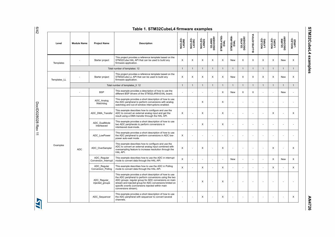
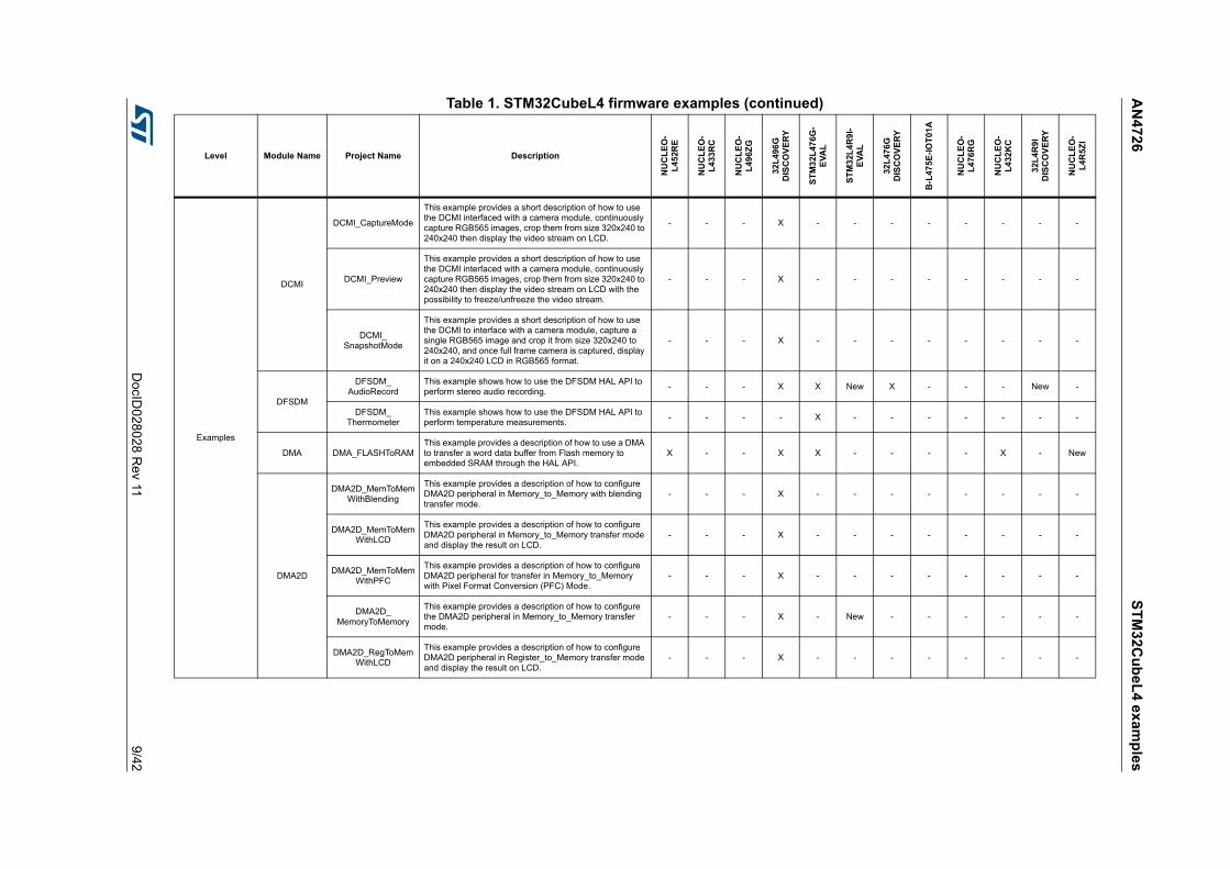
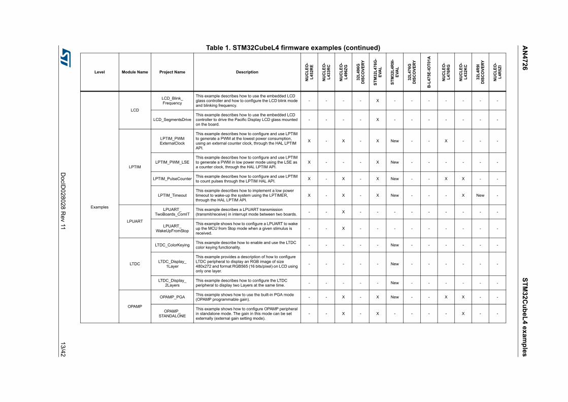
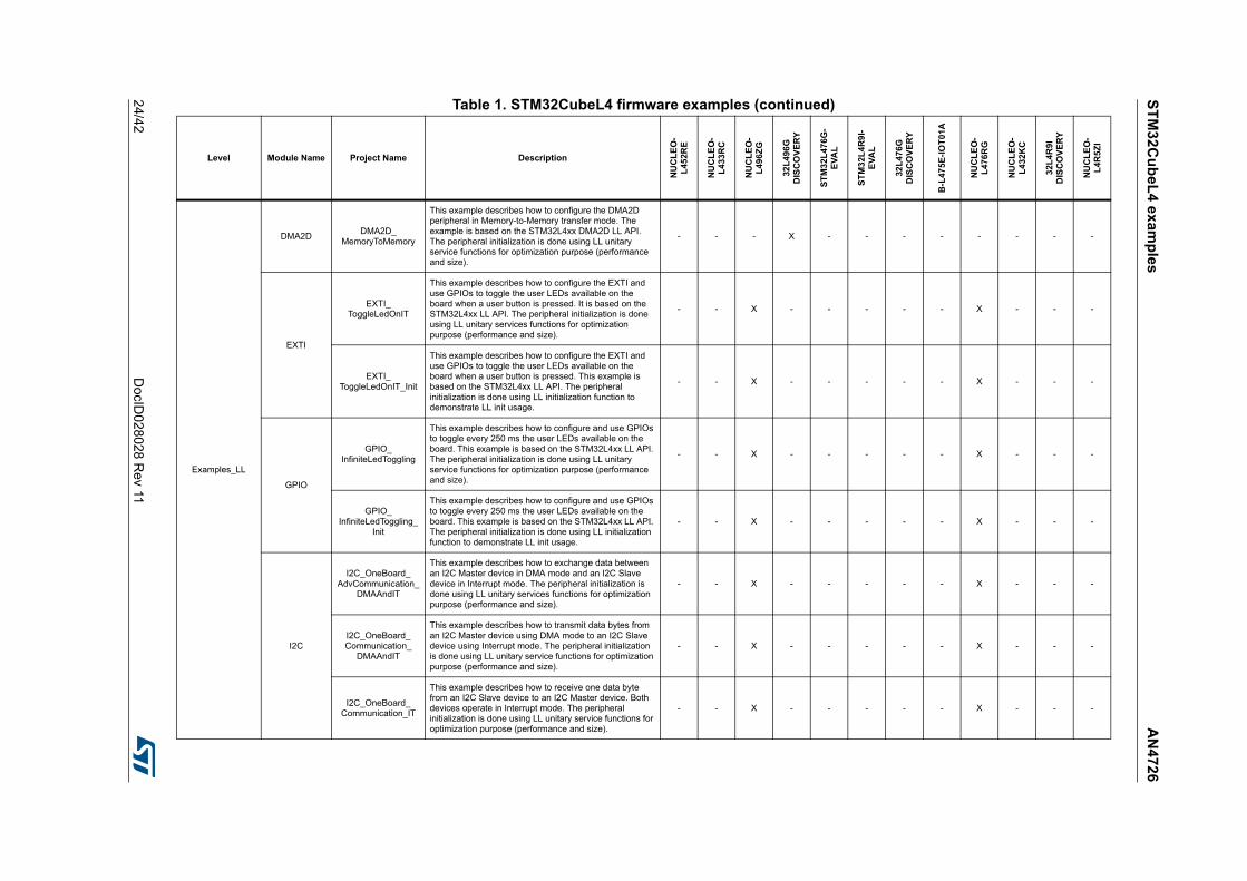
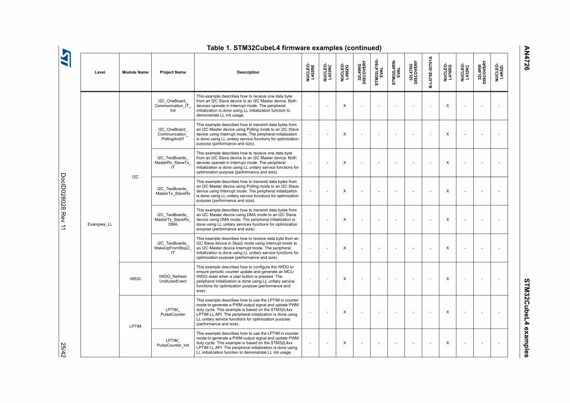
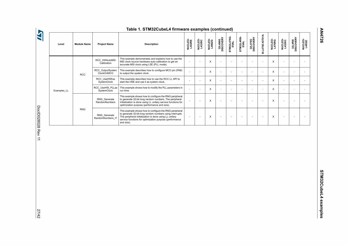
Table 1 contains the list of examples provided within STM32CubeL4 firmware package.
ST
M3
2Cu
be
L4
ex
amp
les
AN
472
6
6/42
DocID
028028 R
ev 11
Table 1. STM32CubeL4 firmware examples
Level Module Name Project Name Description
NU
CL
EO
-L
45
2RE
NU
CL
EO
-L
433R
C
NU
CL
EO
-L
496Z
G
32L
49
6GD
ISC
OV
ER
Y
ST
M3
2L4
76G
-E
VA
L
ST
M32
L4
R9I
-E
VA
L
32L
47
6GD
ISC
OV
ER
Y
B-L
475E
-IO
T01
A
NU
CL
EO
-L
476
RG
NU
CL
EO
-L
432K
C
32L
4R
9ID
ISC
OV
ER
Y
NU
CL
EO
-L
4R5Z
I
Templates- Starter project
This project provides a reference template based on the STM32Cube HAL API that can be used to build any firmware application.
X X X X X New X X X X New X
Total number of templates: 12 1 1 1 1 1 1 1 1 1 1 1 1
Templates_LL- Starter project
This project provides a reference template based on the STM32Cube LL API that can be used to build any firmware application.
X X X X X New X X X X New X
Total number of templates_ll: 12 1 1 1 1 1 1 1 1 1 1 1 1
Examples
- BSPThis example provides a description of how to use the different BSP drivers of the STM32L4R9I-EVAL board.
- - - - X New X X - - New -
ADC
ADC_AnalogWatchdog
This example provides a short description of how to use the ADC peripheral to perform conversions with analog watchdog and out-of-window interruptions enabled.
- - X - X - - - - - - -
ADC_DMA_TransferThis example describes how to configure and use the ADC to convert an external analog input and get the result using a DMA transfer through the HAL API.
X - X - X - - - - X - X
ADC_DualModeInterleaved
This example provides a short description of how to use two ADC peripherals to perform conversions in interleaved dual-mode.
- - X - X - - - - - - -
ADC_LowPowerThis example provides a short description of how to use the ADC peripheral to perform conversions in ADC low-power auto-wait mode.
X - - - - - - - - - - -
ADC_OverSampler
This example describes how to configure and use the ADC to convert an external analog input combined with oversampling feature to increase resolution through the HAL API.
X - X - X - - - - X - X
ADC_RegularConversion_Interrupt
This example describes how to use the ADC in interrupt mode to convert data through the HAL API.
X - - - - New - - - X New X
ADC_RegularConversion_Polling
This example describes how to use the ADC in Polling mode to convert data through the HAL API.
X - X - X - - - - X - X
ADC_Regular_injected_groups
This example provides a short description of how to use the ADC peripheral to perform conversions using the two ADC groups: regular group for ADC conversions on main stream and injected group for ADC conversions limited on specific events (conversions injected within main conversions stream).
- - X - X - - - - - - -
ADC_SequencerThis example provides a short description of how to use the ADC peripheral with sequencer to convert several channels.
- - X - X - - - - - - X

AN
472
6S
TM
32C
ub
eL
4 ex
amp
les
DocID
028028 R
ev 117
/42
Examples
CAN CAN_NetworkingThis example shows how to configure the CAN peripheral to send and receive CAN frames in normal mode.
- - - - X - - - - - - -
COMP
COMP_AnalogWatchdog
This example shows how to make an analog watchdog using the COMP peripherals in window mode.
- - X - X - - - - - - -
COMP_InterruptThis example shows how to configure the COMP peripheral to compare the external voltage applied on a specific pin with the Internal Voltage Reference.
X - X - X - - - X X - -
CRC
CRC_Bytes_Stream_
7bit_CRC
This example guides you through the different configuration steps by means of the HAL API. The CRC (Cyclic Redundancy Check) calculation unit computes 7-bit long CRC codes derived from buffers of 8-bit data (bytes).
- - X - - New - - X X - X
CRC_Data_Reversing_16bit_CRC
This example guides you through the different configuration steps by means of the HAL API. The CRC (Cyclic Redundancy Check) calculation unit computes a 16-bit long CRC code derived from a buffer of 8-bit data (bytes).
- - X - - New - - X X - X
CRC_Example
This example guides you through the different configuration steps by means of the HAL API. The CRC (Cyclic Redundancy Check) calculation unit computes the CRC code of a given buffer of 32-bit data words, using a fixed generator polynomial (0x4C11DB7).
X - X - X New X - X X - X
CRC_UserDefinedPolynomial
This example guides you through the different configuration steps by means of the HAL API. The CRC (Cyclic Redundancy Check) calculation unit computes the 8-bit long CRC code of a given buffer of 32-bit data words, based on a user-defined generating polynomial.
X - X - X New X - X X - X
Table 1. STM32CubeL4 firmware examples (continued)
Level Module Name Project Name Description
NU
CL
EO
-L
452R
E
NU
CL
EO
-L
433
RC
NU
CL
EO
-L
496Z
G
32L
496
GD
ISC
OV
ER
Y
ST
M3
2L
476G
-E
VA
L
ST
M3
2L4
R9
I-E
VA
L
32L
476
GD
ISC
OV
ER
Y
B-L
475
E-I
OT
01A
NU
CL
EO
-L
476
RG
NU
CL
EO
-L
432
KC
32L
4R
9I
DIS
CO
VE
RY
NU
CL
EO
-L
4R5Z
I

ST
M3
2Cu
be
L4
ex
amp
les
AN
472
6
8/42
DocID
028028 R
ev 11
Examples
CRYP
CRYP_AESModesThis example provides a short description of how to use the CRYP peripheral to encrypt and decrypt data using AES in chaining modes (ECB, CBC, CTR).
X - X - X - - - - - - -
CRYP_AESModes_Suspension
This example provides a short description of how to use the CRYP AES peripheral to suspend then resume the AES ECB, CBC and CTR processing of a message in order to carry out the encryption or decryption of a higher priority message.
X - X - X - - - - - - -
CRYP_DMA
This example provides a short description of how to use the CRYP peripheral to encrypt and decrypt data using AES 128 Algorithm with ECB chaining mode in DMA mode.
X - X - X - - - - - - -
CRYP_GCM_GMAC_CMAC_Modes
This example describes how to encrypt, decrypt data and compute authentication tag with GCM, GMAC and CMAC AES algorithms.
X - X - X - - - - - - -
CRYP_GCM_GMAC_CMAC_Suspension
This example provides a short description of how to use the CRYP AES peripheral to suspend then resume the AES GCM, GMAC and CMAC processing of a message in order to carry out the encryption, decryption or authentication tag computation of a higher priority message.
X - X - X - - - - - - -
Cortex
CORTEXM_MPU
This example presents the MPU feature. Its purpose is to configure a memory area as privileged read-only area and attempt to perform read and write operations in different modes.
X - X - X - - - X X - -
CORTEXM_ModePrivilege
This example shows how to modify Thread mode privilege access and stack. Thread mode is entered on reset or when returning from an exception.
X - X - X - - - X X - -
CORTEXM_ProcessStack
This example shows how to modify Thread mode stack. Thread mode is entered on Reset, and can be entered as a result of an exception return.
X - X - - - - - - - - -
CORTEXM_SysTick
This example shows how to use the default SysTick configuration with a 1 ms timebase to toggle LEDs.
X - X - X - - - X X - -
DAC
DAC_SignalsGeneration
This example provides a description of how to use the DAC peripheral to generate several signals using DMA controller.
X - X - X New - - X X - -
DAC_SimpleConversion
This example provides a short description of how to use the DAC peripheral to do a simple conversion.
X - X - X - - - X - - -
Table 1. STM32CubeL4 firmware examples (continued)
Level Module Name Project Name Description
NU
CL
EO
-L
452R
E
NU
CL
EO
-L
433
RC
NU
CL
EO
-L
496Z
G
32L
496
GD
ISC
OV
ER
Y
ST
M3
2L
476G
-E
VA
L
ST
M3
2L4
R9
I-E
VA
L
32L
476
GD
ISC
OV
ER
Y
B-L
475
E-I
OT
01A
NU
CL
EO
-L
476
RG
NU
CL
EO
-L
432
KC
32L
4R
9I
DIS
CO
VE
RY
NU
CL
EO
-L
4R5Z
I
AN
472
6S
TM
32C
ub
eL
4 ex
amp
les
DocID
028028 R
ev 119
/42
Examples
DCMI
DCMI_CaptureMode
This example provides a short description of how to use the DCMI interfaced with a camera module, continuously capture RGB565 images, crop them from size 320x240 to 240x240 then display the video stream on LCD.
- - - X - - - - - - - -
DCMI_Preview
This example provides a short description of how to use the DCMI interfaced with a camera module, continuously capture RGB565 images, crop them from size 320x240 to 240x240 then display the video stream on LCD with the possibility to freeze/unfreeze the video stream.
- - - X - - - - - - - -
DCMI_SnapshotMode
This example provides a short description of how to use the DCMI to interface with a camera module, capture a single RGB565 image and crop it from size 320x240 to 240x240, and once full frame camera is captured, display it on a 240x240 LCD in RGB565 format.
- - - X - - - - - - - -
DFSDM
DFSDM_AudioRecord
This example shows how to use the DFSDM HAL API to perform stereo audio recording.
- - - X X New X - - - New -
DFSDM_Thermometer
This example shows how to use the DFSDM HAL API to perform temperature measurements.
- - - - X - - - - - - -
DMA DMA_FLASHToRAMThis example provides a description of how to use a DMA to transfer a word data buffer from Flash memory to embedded SRAM through the HAL API.
X - - X X - - - - X - New
DMA2D
DMA2D_MemToMemWithBlending
This example provides a description of how to configure DMA2D peripheral in Memory_to_Memory with blending transfer mode.
- - - X - - - - - - - -
DMA2D_MemToMemWithLCD
This example provides a description of how to configure DMA2D peripheral in Memory_to_Memory transfer mode and display the result on LCD.
- - - X - - - - - - - -
DMA2D_MemToMemWithPFC
This example provides a description of how to configure DMA2D peripheral for transfer in Memory_to_Memory with Pixel Format Conversion (PFC) Mode.
- - - X - - - - - - - -
DMA2D_MemoryToMemory
This example provides a description of how to configure the DMA2D peripheral in Memory_to_Memory transfer mode.
- - - X - New - - - - - -
DMA2D_RegToMemWithLCD
This example provides a description of how to configure DMA2D peripheral in Register_to_Memory transfer mode and display the result on LCD.
- - - X - - - - - - - -
Table 1. STM32CubeL4 firmware examples (continued)
Level Module Name Project Name Description
NU
CL
EO
-L
452R
E
NU
CL
EO
-L
433
RC
NU
CL
EO
-L
496Z
G
32L
496
GD
ISC
OV
ER
Y
ST
M3
2L
476G
-E
VA
L
ST
M3
2L4
R9
I-E
VA
L
32L
476
GD
ISC
OV
ER
Y
B-L
475
E-I
OT
01A
NU
CL
EO
-L
476
RG
NU
CL
EO
-L
432
KC
32L
4R
9I
DIS
CO
VE
RY
NU
CL
EO
-L
4R5Z
I

ST
M3
2Cu
be
L4
ex
amp
les
AN
472
6
10/4
2D
ocID028
028 Rev 11 Examples
DSI
DSI_CmdMode_SingleBuffer
This example provides a description of how to use the embedded LCD DSI controller (using IPs GFXMMU, LTDC and DSI Host) to drive the round LCD mounted on board and display a 390x390 RGB image on LCD in Command mode using a single buffer for draw.
- - - - - New - - - - New -
DSI_ULPM_Data
This example provides a description of how to use the embedded LCD DSI controller (using IPs GFXMMU, LTDC and DSI Host) to drive the round LCD mounted on board and manage entry and exit in DSI ULPM mode on data lane only. In this mode, the DSI PHY state machine is entering a low power state on data lane and allows to save some power when the LCD does not need to display. When the display is needed again, the DSI ULPM on data lane is exited and display should operate as before.
- - - - - New - - - - New -
DSI_ULPM_DataClock
This example provides a description of how to use the embedded LCD DSI controller (using IPs GFXMMU, LTDC and DSI Host) to drive the round LCD mounted on board and manage entry and exit in DSI ULPM mode on data lane and clock lane. In this mode, the DSI PHY state machine is entering a low power state on data lane and clock lane.
- - - - - New - - - - New -
FIREWALL
FIREWALL_VolatileData_Executable
This example shows how to use the Firewall peripherak to protect a volatile data segment and define it as executable.
- - X - - - - - X - - -
FIREWALL_VolatileData_Shared
This example shows how to use the Firewall peripheral to protect a code segment as well as volatile and non-volatile data segments.
- - X - - - - - X - - -
FLASH
FLASH_DualBoot
This example guides you through the different configuration steps to program the internal flash memory bank 1 and bank 2 and to swap between both of them by mean of the FLASH HAL API.
- - X X X - X - X - - -
FLASH_EraseProgram
This example describes how to configure and use the FLASH HAL API to erase and program the internal Flash memory.
X - X X X New X - X X New New
FLASH_FastProgramThis example describes how to configure and use the FLASH HAL API to erase and fast program the internal Flash memory.
X - X X X New X - X - New New
FLASH_WriteProtection
This example describes how to configure and use the FLASH HAL API to enable and disable the write protection of the internal Flash memory.
X - X X X New X - X X - New
FMC
FMC_NORThis example describes how to configure the FMC controller to access the NOR memory.
- - - - X New - - - - - -
FMC_SRAMThis example describes how to configure the FMC controller to access the SRAM memory.
- - - - X New - - - - - -
Table 1. STM32CubeL4 firmware examples (continued)
Level Module Name Project Name Description
NU
CL
EO
-L
452R
E
NU
CL
EO
-L
433
RC
NU
CL
EO
-L
496Z
G
32L
496
GD
ISC
OV
ER
Y
ST
M3
2L
476G
-E
VA
L
ST
M3
2L4
R9
I-E
VA
L
32L
476
GD
ISC
OV
ER
Y
B-L
475
E-I
OT
01A
NU
CL
EO
-L
476
RG
NU
CL
EO
-L
432
KC
32L
4R
9I
DIS
CO
VE
RY
NU
CL
EO
-L
4R5Z
I

AN
472
6S
TM
32C
ub
eL
4 ex
amp
les
DocID
028028 R
ev 1111
/42
Examples
GPIO
GPIO_EXTIThis example shows how to configure external interrupt lines to wake up from low power mode.
X - X X X New X - X - - -
GPIO_IOToggleThis example describes how to configure and use GPIOs through the HAL API.
X - X X X New X - X X - -
HAL HAL_TimeBase_TIMThis example describes how to customize the HAL timebase using a general- purpose timer instead of the Systick as main timebase source.
X - X - X New - - X - - -
HASH
HASH_HMAC_SHA1MD5
This example provides a short description of how to use the HASH peripheral to hash data using HMAC SHA-1 and HMAC MD5 algorithms.
- - X - - - - - - - - X
HASH_HMAC_SHA224SHA1_DMA_
Suspension
This example describes how to suspend the HMAC digest computation when data are fed to the HASH IP by DMA.
- - - - - - - - - - - X
HASH_HMAC_SHA224SHA256_
MultiBuffer_DMA
This example describes how to handle text messages longer than the maximum DMA transfer length. In this case, the input data have to be split into several buffers with sizes within the DMA limit, and the buffers must be consecutively fed to the HASH peripheral.
- - X - - - - - - - - X
HASH_HMAC_SHA256MD5_IT_Suspension
This example describes how to suspend the HMAC digest computation when data are fed in Interrupt mode.
- - X - - - - - - - - X
HASH_SHA1MD5This example provides a short description of how to use the HASH peripheral to hash data using SHA-1 and MD5 algorithms.
- - X - - - - - - - - X
HASH_SHA1MD5_DMA
This example provides a short description of how to use the HASH peripheral to hash data using SHA-1 and MD5 algorithms when data are fed to the HASH IP by DMA.
- - X - - - - - - - - X
HASH_SHA1SHA224_IT_Suspension
This example describes how to suspend the HASH peripheral when data are fed in Interrupt mode.
- - X - - - - - - - - X
HASH_SHA224SHA256_DMA
This example provides a short description of how to use the HASH peripheral to hash data using SHA224 and SHA256 algorithms.
- - X - - - - - - - - X
HASH_SHA256MD5_DMA_Suspension
This example describes how to suspend the HASH peripheral when data are fed to the HASH IP by DMA.
- - - - - - - - - - - X
Table 1. STM32CubeL4 firmware examples (continued)
Level Module Name Project Name Description
NU
CL
EO
-L
452R
E
NU
CL
EO
-L
433
RC
NU
CL
EO
-L
496Z
G
32L
496
GD
ISC
OV
ER
Y
ST
M3
2L
476G
-E
VA
L
ST
M3
2L4
R9
I-E
VA
L
32L
476
GD
ISC
OV
ER
Y
B-L
475
E-I
OT
01A
NU
CL
EO
-L
476
RG
NU
CL
EO
-L
432
KC
32L
4R
9I
DIS
CO
VE
RY
NU
CL
EO
-L
4R5Z
I

ST
M3
2Cu
be
L4
ex
amp
les
AN
472
6
12/4
2D
ocID028
028 Rev 11
Examples
I2C
I2C_EEPROMThis example describes how to ensure I2C data buffer transmission/reception with DMA. Data are exchanged with an I2C EEPROM memory.
- - - - X New - - - - - -
I2C_IOExpanderThis example describes how to perform I2C data communication with the I/O expander device mounted on the evaluation board.
- - - - X - - - - - - -
I2C_TwoBoards_AdvComIT
This example describes how to perform I2C data buffer transmission/reception between two boards, using an interrupt.
X - X - X - - - X X - X
I2C_TwoBoards_ComDMA
This example describes how to perform I2C data buffer transmission/reception between two boards, via DMA.
X - X - X - - - X X - X
I2C_TwoBoards_ComIT
This example describes how to perform I2C data buffer transmission/reception between two boards using an interrupt.
X - X - X - - - X X - X
I2C_TwoBoards_ComPolling
This example describes how to perform I2C data buffer transmission/reception between two boards in Polling mode.
X - X - X - - - X - - X
I2C_TwoBoards_RestartAdvComIT
This example describes how to perform a multiple I2C data buffer transmission/reception between two boards in Interrupt mode and with a restart condition.
X - X - X - - - X X - X
I2C_TwoBoards_RestartComIT
This example describes how to perform a single I2C data buffer transmission/reception between two boards in Interrupt mode and with a restart condition.
X - X - X - - - X X - X
I2C_WakeUpFromStop
This example describes how to perform I2C data buffer transmission/reception between two boards using an interrupt when the device is in Stop mode.
- - X - X - - - X X - -
I2C_WakeUpFromStop2
This example describes how to perform I2C data buffer transmission/reception between two boards using an interrupt when the device is in Stop 2 mode.
X - X - X - - - X - - -
IWDG
IWDG_Reset
This example describes how to ensure IWDG reload counter and simulate a software fault that generates an MCU IWDG reset when a programmed time period has elapsed.
X - X - X New - - X - - -
IWDG_WindowMode
This example describes how to periodically update the IWDG reload counter and simulate a software fault that generates an MCU IWDG reset when a programmed time period has elapsed.
X - X - X New - - X - - -
Table 1. STM32CubeL4 firmware examples (continued)
Level Module Name Project Name Description
NU
CL
EO
-L
452R
E
NU
CL
EO
-L
433
RC
NU
CL
EO
-L
496Z
G
32L
496
GD
ISC
OV
ER
Y
ST
M3
2L
476G
-E
VA
L
ST
M3
2L4
R9
I-E
VA
L
32L
476
GD
ISC
OV
ER
Y
B-L
475
E-I
OT
01A
NU
CL
EO
-L
476
RG
NU
CL
EO
-L
432
KC
32L
4R
9I
DIS
CO
VE
RY
NU
CL
EO
-L
4R5Z
I
AN
472
6S
TM
32C
ub
eL
4 ex
amp
les
DocID
028028 R
ev 1113
/42
Examples
LCD
LCD_Blink_Frequency
This example describes how to use the embedded LCD glass controller and how to configure the LCD blink mode and blinking frequency.
- - - - X - - - - - - -
LCD_SegmentsDriveThis example describes how to use the embedded LCD controller to drive the Pacific Display LCD glass mounted on the board.
- - - - X - - - - - - -
LPTIM
LPTIM_PWMExternalClock
This example describes how to configure and use LPTIM to generate a PWM at the lowest power consumption, using an external counter clock, through the HAL LPTIM API.
X - X - X New - - X - - -
LPTIM_PWM_LSEThis example describes how to configure and use LPTIM to generate a PWM in low power mode using the LSE as a counter clock, through the HAL LPTIM API.
X - - - X New - - - - - -
LPTIM_PulseCounterThis example describes how to configure and use LPTIM to count pulses through the LPTIM HAL API.
X - X - X New - - X X - -
LPTIM_TimeoutThis example describes how to implement a low power timeout to wake-up the system using the LPTIMER, through the HAL LPTIM API.
X - X - X New - - - X New -
LPUART
LPUART_TwoBoards_ComIT
This example describes a LPUART transmission (transmit/receive) in interrupt mode between two boards.
- - X - - - - - - - - -
LPUART_WakeUpFromStop
This example shows how to configure a LPUART to wake up the MCU from Stop mode when a given stimulus is received.
- - X - - - - - - - - -
LTDC
LTDC_ColorKeyingThis example describe how to enable and use the LTDC color keying functionality.
- - - - - New - - - - - -
LTDC_Display_1Layer
This example provides a description of how to configure LTDC peripheral to display an RGB image of size 480x272 and format RGB565 (16 bits/pixel) on LCD using only one layer.
- - - - - New - - - - - -
LTDC_Display_2Layers
This example describes how to configure the LTDC peripheral to display two Layers at the same time.
- - - - - New - - - - - -
OPAMP
OPAMP_PGAThis example shows how to use the built-in PGA mode (OPAMP programmable gain).
- - X - X New - - X X - -
OPAMP_STANDALONE
This example shows how to configure OPAMP peripheral in standalone mode. The gain in this mode can be set externally (external gain setting mode).
- - X - X - - - - X - -
Table 1. STM32CubeL4 firmware examples (continued)
Level Module Name Project Name Description
NU
CL
EO
-L
452R
E
NU
CL
EO
-L
433
RC
NU
CL
EO
-L
496Z
G
32L
496
GD
ISC
OV
ER
Y
ST
M3
2L
476G
-E
VA
L
ST
M3
2L4
R9
I-E
VA
L
32L
476
GD
ISC
OV
ER
Y
B-L
475
E-I
OT
01A
NU
CL
EO
-L
476
RG
NU
CL
EO
-L
432
KC
32L
4R
9I
DIS
CO
VE
RY
NU
CL
EO
-L
4R5Z
I

ST
M3
2Cu
be
L4
ex
amp
les
AN
472
6
14/4
2D
ocID028
028 Rev 11
Examples
OSPI
OSPI_NOR_ExecuteInPlace
This example describes how to execute a part of the code from the OctoSPI NOR Flash memory. To do this, a section is created where the function is stored.
- - - - - New - - - - - -
OSPI_NOR_ExecuteInPlace_DTR
This example describes how to execute a part of the code from the OctoSPI NOR Flash memory. To do this, a section is created where the function is stored. The memory is configured in octal DTR mode.
- - - - - New - - - - - -
OSPI_NOR_MemoryMapped
This example describes how to erase part of the OctoSPI NOR Flash memory, write data in memory-mapped mode and access to OctoSPI NOR Flash memory in memory-mapped mode to check the data in a forever loop.
- - - - - New - - - - New -
OSPI_NOR_MemoryMapped_DTR
This example describes how to erase part of the OctoSPI NOR Flash memory, write data in memory-mapped mode and access to OctoSPI NOR Flash memory in memory-mapped mode to check the data in a forever loop. The memory is configured in octal DTR mode.
- - - - - New - - - - New -
OSPI_NOR_ReadWrite_DMA
This example describes how to erase part of the OctoSPI NOR Flash memory, write data in DMA mode, read data in DMA mode and compare the result in a forever loop.
- - - - - New - - - - New -
OSPI_NOR_ReadWrite_DMA_
DTR
This example describes how to erase part of the OctoSPI NOR Flash memory, write data in DMA mode, read data in DMA mode and compare the result in a forever loop. The memory is configured in octal DTR mode.
- - - - - New - - - - New -
OSPI_RAM_ExecuteInPlace
This example describes how to execute a part of the code from the OctoSPI HyperRAM memory. To do this, a section is created where the function is stored.
- - - - - New - - - - - -
OSPI_RAM_MemoryMapped
This example describes how to write and read data in memory-mapped mode in the OctoSPI HyperRAM memory and compare the result in a forever loop.
- - - - - New - - - - - -
OSPI_RAM_ReadWrite_DMA
This example describes how to write data in DMA mode in the OctoSPI HyperRAM memory, read data in DMA mode and compare the result in a forever loop.
- - - - - New - - - - - -
PWR
PWR_LPRUNThis example shows how to enter and exit the Low-power Run mode.
X - X - - - - - X X - X
PWR_LPRUN_SRAM1
This example shows how to enter and exit the Low-power Run mode when executing code from SRAM1.
X - X - - - - - X X - X
PWR_LPSLEEPThis example shows how to enter Low-power sleep mode and wake up from this mode using an interrupt.
X - X - - - - - X X - X
Table 1. STM32CubeL4 firmware examples (continued)
Level Module Name Project Name Description
NU
CL
EO
-L
452R
E
NU
CL
EO
-L
433
RC
NU
CL
EO
-L
496Z
G
32L
496
GD
ISC
OV
ER
Y
ST
M3
2L
476G
-E
VA
L
ST
M3
2L4
R9
I-E
VA
L
32L
476
GD
ISC
OV
ER
Y
B-L
475
E-I
OT
01A
NU
CL
EO
-L
476
RG
NU
CL
EO
-L
432
KC
32L
4R
9I
DIS
CO
VE
RY
NU
CL
EO
-L
4R5Z
I
AN
472
6S
TM
32C
ub
eL
4 ex
amp
les
DocID
028028 R
ev 1115
/42
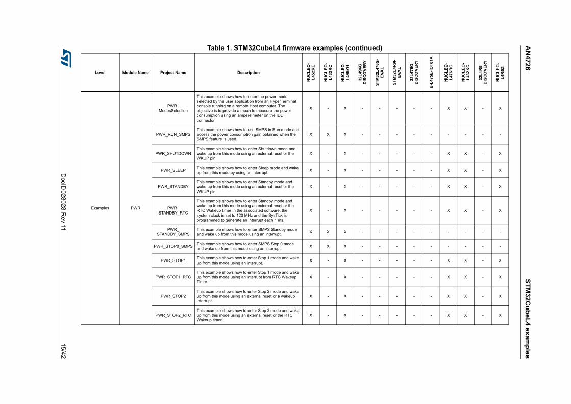
Examples PWR
PWR_ModesSelection
This example shows how to enter the power mode selected by the user application from an HyperTerminal console running on a remote Host computer. The objective is to provide a mean to measure the power consumption using an ampere meter on the IDD connector.
X - X - - - - - X X - X
PWR_RUN_SMPSThis example shows how to use SMPS in Run mode and access the power consumption gain obtained when the SMPS feature is used.
X X X - - - - - - - - -
PWR_SHUTDOWNThis example shows how to enter Shutdown mode and wake up from this mode using an external reset or the WKUP pin.
X - X - - - - - X X - X
PWR_SLEEPThis example shows how to enter Sleep mode and wake up from this mode by using an interrupt.
X - X - - - - - X X - X
PWR_STANDBYThis example shows how to enter Standby mode and wake up from this mode using an external reset or the WKUP pin.
X - X - - - - - X X - X
PWR_STANDBY_RTC
This example shows how to enter Standby mode and wake up from this mode using an external reset or the RTC Wakeup timer In the associated software, the system clock is set to 120 MHz and the SysTick is programmed to generate an interrupt each 1 ms.
X - X - - - - - X X - X
PWR_STANDBY_SMPS
This example shows how to enter SMPS Standby mode and wake up from this mode using an interrupt.
X X X - - - - - - - - -
PWR_STOP0_SMPSThis example shows how to enter SMPS Stop 0 mode and wake up from this mode using an interrupt.
X X X - - - - - - - - -
PWR_STOP1This example shows how to enter Stop 1 mode and wake up from this mode using an interrupt.
X - X - - - - - X X - X
PWR_STOP1_RTCThis example shows how to enter Stop 1 mode and wake up from this mode using an interrupt from RTC Wakeup Timer.
X - X - - - - - X X - X
PWR_STOP2This example shows how to enter Stop 2 mode and wake up from this mode using an external reset or a wakeup interrupt.
X - X - - - - - X X - X
PWR_STOP2_RTCThis example shows how to enter Stop 2 mode and wake up from this mode using an external reset or the RTC Wakeup timer.
X - X - - - - - X X - X
Table 1. STM32CubeL4 firmware examples (continued)
Level Module Name Project Name Description
NU
CL
EO
-L
452R
E
NU
CL
EO
-L
433
RC
NU
CL
EO
-L
496Z
G
32L
496
GD
ISC
OV
ER
Y
ST
M3
2L
476G
-E
VA
L
ST
M3
2L4
R9
I-E
VA
L
32L
476
GD
ISC
OV
ER
Y
B-L
475
E-I
OT
01A
NU
CL
EO
-L
476
RG
NU
CL
EO
-L
432
KC
32L
4R
9I
DIS
CO
VE
RY
NU
CL
EO
-L
4R5Z
I

ST
M3
2Cu
be
L4
ex
amp
les
AN
472
6
16/4
2D
ocID028
028 Rev 11
Examples
QSPI
QSPI_ExecuteInPlace
This example describes how to execute a part of the code from the QuadSPI Flash memory. To do this, a section is created where the function is stored.
- - - X X - X - - - - -
QSPI_MemoryMapped
This example describes how to erase part of the QuadSPI Flash memory, write data in DMA mode and access to QuadSPI Flash memory in memory-mapped mode to check the data in a forever loop.
- - - X X - X - - - - -
QSPI_PreInitConfig
This example describes how to execute a part of the code from the QuadSPI Flash memory configured in memory-mapped mode before the call to main() function so that QuadSPI Flash memory is available after the reset.
- - - X X - X - - - - -
QSPI_ReadWrite_DMA
This example describes how to erase part of the QuadSPI Flash memory, write data in DMA mode, read data in DMA mode and compare the result in a forever loop.
- - - X X - X - - - - -
QSPI_ReadWrite_ITThis example describes how to erase part of the QuadSPI Flash memory, write data in Interrupt mode, read data in Interrupt mode and compare the result in a forever loop.
- - - X X - X - - - - -
RCC
RCC_CRS_Synchronization_IT
This example describes how to use the RCC HAL API to configure the clock recovery service (CRS) in Interrupt mode.
X - X - - - - - - X - -
RCC_CRS_Synchronization_
Polling
This example describes how to use the RCC HAL API to configure the clock recovery service (CRS) in Polling mode.
X - X - - - - - - X - -
RCC_ClockConfigThis example describes how to use the RCC HAL API to configure the system clock (SYSCLK) and modify the clock settings in Run mode.
X - X - X New X - X - New New
RNG
RNG_MultiRNGThis example guides you through the HAL API different configuration steps to ensure 32-bit long random numbers generation by RNG peripheral.
X - X - X New - - - X - X
RNG_MultiRNG_ITThis example guides you through the HAL API different configuration steps to ensure 32-bit long random numbers generation by RNG peripheral interruptions.
X - X - X New - - - X - X
Table 1. STM32CubeL4 firmware examples (continued)
Level Module Name Project Name Description
NU
CL
EO
-L
452R
E
NU
CL
EO
-L
433
RC
NU
CL
EO
-L
496Z
G
32L
496
GD
ISC
OV
ER
Y
ST
M3
2L
476G
-E
VA
L
ST
M3
2L4
R9
I-E
VA
L
32L
476
GD
ISC
OV
ER
Y
B-L
475
E-I
OT
01A
NU
CL
EO
-L
476
RG
NU
CL
EO
-L
432
KC
32L
4R
9I
DIS
CO
VE
RY
NU
CL
EO
-L
4R5Z
I

AN
472
6S
TM
32C
ub
eL
4 ex
amp
les
DocID
028028 R
ev 1117
/42
Examples
RTC
RTC_AlarmThis example guides you through the different configuration steps by means of the RTC HAL API to configure and generate an RTC alarm.
X - - X X New - - X X - New
RTC_CalendarThis example guides you through the different configuration steps by mean of HAL API to ensure Calendar configuration using the RTC peripheral.
X - - - X New - - - - - -
RTC_InternalTimeStamp
This example guides you through the different configuration steps by means of the RTC HAL API to demonstrate the internal timestamp feature.
- - - - X - - - - - - -
RTC_LSIThis example demonstrates and explains how to use the LSI clock source auto calibration to get a precise RTC clock.
X - X - X New - - X X - New
RTC_LowPower_STANDBY
This example shows how to enter Standby mode and wake up from this mode using the RTC alarm event.
X - - - - - - - - - - -
RTC_Tamper
This example guides you through the different configuration steps by means of the RTC HAL API to write/read data to/from RTC Backup registers. It also demonstrates the tamper detection feature.
X - X - X New - - X - - New
RTC_TimeStampThis example guides you through the different configuration steps by means of the RTC HAL API to demonstrate the timestamp feature.
X - X - X New - - X - New New
SAI SAI_AudioPlayThis example shows how to use the SAI HAL API to play an audio file using the DMA circular mode and how to handle the buffer update.
- - - - X New X - - - New -
SMARTCARD SMARTCARD_T0
This example describes a firmware smartcard Interface based on USART. The main purpose of this firmware example is to provide resources that ease the development of applications using USART in smartcard mode.
- - - - X - - - - - - -
SPI
SPI_FullDuplex_ComDMA
This example shows how to perform SPI data buffer transmission/reception between two boards via DMA.
X - X - - - - - X X - X
SPI_FullDuplex_ComIT
This example shows how to ensure SPI data buffer transmission/reception between two boards by using an interrupt.
X - X - - - - - X X - X
SPI_FullDuplex_ComPolling
This example shows how to ensure SPI data buffer transmission/reception in Polling mode between two boards.
X - X - - - - - X X - X
SPI_HalfDuplex_ComPolling
This example shows how to ensure SPI data buffer half-duplex transmission/reception in Polling mode between two boards.
X - X - - - - - X - - -
Table 1. STM32CubeL4 firmware examples (continued)
Level Module Name Project Name Description
NU
CL
EO
-L
452R
E
NU
CL
EO
-L
433
RC
NU
CL
EO
-L
496Z
G
32L
496
GD
ISC
OV
ER
Y
ST
M3
2L
476G
-E
VA
L
ST
M3
2L4
R9
I-E
VA
L
32L
476
GD
ISC
OV
ER
Y
B-L
475
E-I
OT
01A
NU
CL
EO
-L
476
RG
NU
CL
EO
-L
432
KC
32L
4R
9I
DIS
CO
VE
RY
NU
CL
EO
-L
4R5Z
I

ST
M3
2Cu
be
L4
ex
amp
les
AN
472
6
18/4
2D
ocID028
028 Rev 11
Examples
SWPMI SWPMI_SessionThis example shows how to use the SWPMI interface and open a communication session with a SWP compliant card in no software buffer mode.
- - - - X - - - - - - -
TIM
TIM_DMAThis example provides a description of how to use DMA with TIMER Update request to transfer Data from memory to TIMER Capture Compare Register 3 (TIMx_CCR3).
X - X - X - - - X X - -
TIM_DMABurstThis example shows how to update the TIMER channel1 period and the duty cycle using the TIMER DMA burst feature.
X - X - X - - - X X - -
TIM_ExtTriggerSynchro
This example shows how to synchronize TIM peripherals in cascade mode with an external trigger.
X - X - X - - - X - - -
TIM_InputCaptureThis example shows how to use the TIM peripheral to measure the frequency of an external signal.
X - X - X - - - X X - -
TIM_OCActive
This example shows how to configure the TIM peripheral in Output Compare Active mode (when the counter matches the capture/compare register, the concerned output pin is set to its active state).
X - X - X - - - X X - -
TIM_OCInactiveThis example shows how to configure the TIM peripheral in Output Compare Inactive mode with the corresponding Interrupt requests for each channel.
X - X - X - - - X X - -
TIM_OCToggleThis example shows how to configure the TIM peripheral to generate four different signals with four different frequencies.
X - X - X - - - X X - -
TIM_OnePulseThis example shows how to use the TIM peripheral to generate a single pulse when a rising edge of an external signal is received on the timer Input pin.
X - X - X - - - X X - -
TIM_PWMInputThis example shows how to use the TIM peripheral to measure the frequency and duty cycle of an external signal.
X - X - X - - - X X - -
TIM_PWMOutputThis example shows how to configure the TIM peripheral in PWM (Pulse Width Modulation) mode.
X - X - X New - - X X - -
TIM_TimeBaseThis example shows how to configure the TIM peripheral to generate a time base of one second with the corresponding Interrupt request.
X - X - X - - - X X - -
TSCTSC_Basic
Acquisition_Interrupt
This example describes how to use the HAL TSC to perform continuous acquisitions of one channel in interrupt mode.
- - - - X - - - - - - -
Table 1. STM32CubeL4 firmware examples (continued)
Level Module Name Project Name Description
NU
CL
EO
-L
452R
E
NU
CL
EO
-L
433
RC
NU
CL
EO
-L
496Z
G
32L
496
GD
ISC
OV
ER
Y
ST
M3
2L
476G
-E
VA
L
ST
M3
2L4
R9
I-E
VA
L
32L
476
GD
ISC
OV
ER
Y
B-L
475
E-I
OT
01A
NU
CL
EO
-L
476
RG
NU
CL
EO
-L
432
KC
32L
4R
9I
DIS
CO
VE
RY
NU
CL
EO
-L
4R5Z
I
AN
472
6S
TM
32C
ub
eL
4 ex
amp
les
DocID
028028 R
ev 1119
/42
Examples
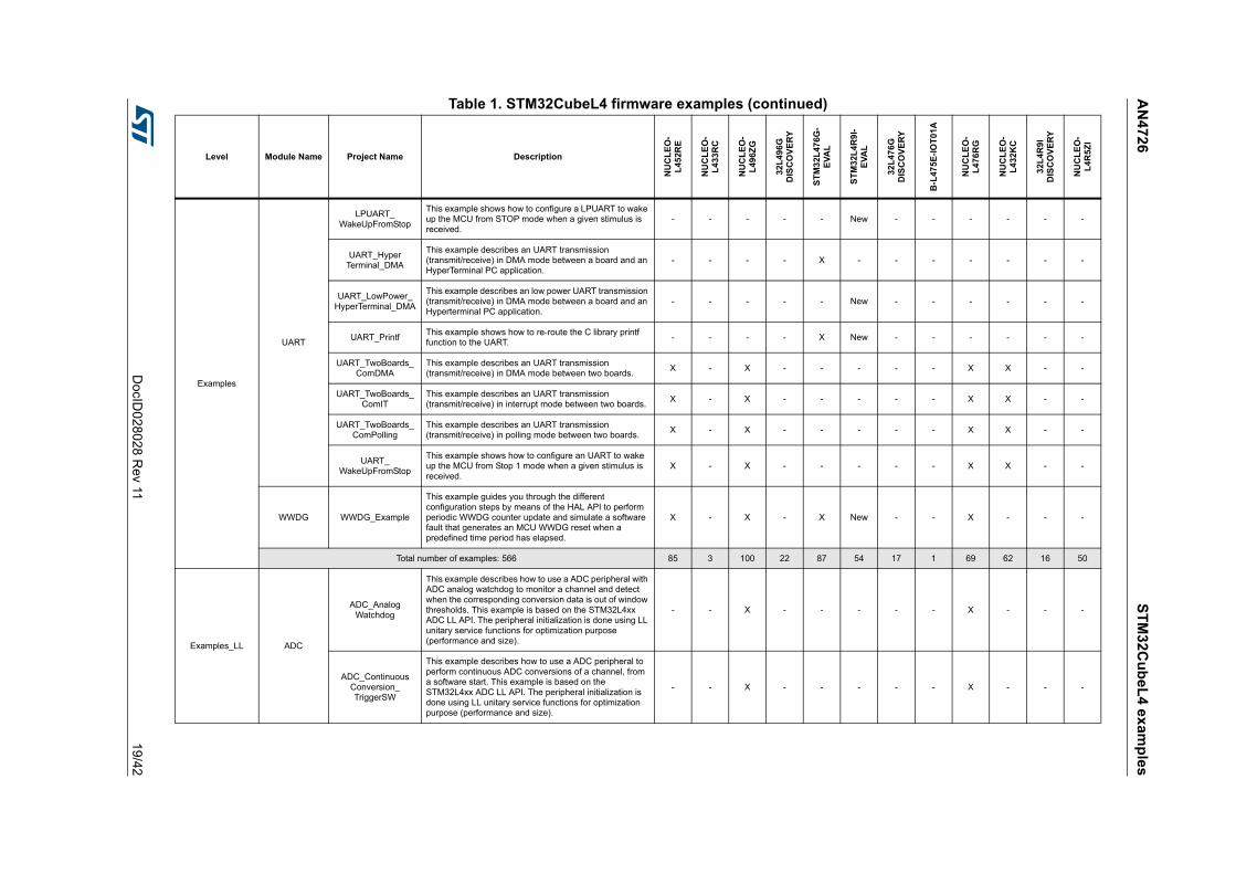
UART
LPUART_WakeUpFromStop
This example shows how to configure a LPUART to wake up the MCU from STOP mode when a given stimulus is received.
- - - - - New - - - - - -
UART_HyperTerminal_DMA
This example describes an UART transmission (transmit/receive) in DMA mode between a board and an HyperTerminal PC application.
- - - - X - - - - - - -
UART_LowPower_HyperTerminal_DMA
This example describes an low power UART transmission (transmit/receive) in DMA mode between a board and an Hyperterminal PC application.
- - - - - New - - - - - -
UART_PrintfThis example shows how to re-route the C library printf function to the UART.
- - - - X New - - - - - -
UART_TwoBoards_ComDMA
This example describes an UART transmission (transmit/receive) in DMA mode between two boards.
X - X - - - - - X X - -
UART_TwoBoards_ComIT
This example describes an UART transmission (transmit/receive) in interrupt mode between two boards.
X - X - - - - - X X - -
UART_TwoBoards_ComPolling
This example describes an UART transmission (transmit/receive) in polling mode between two boards.
X - X - - - - - X X - -
UART_WakeUpFromStop
This example shows how to configure an UART to wake up the MCU from Stop 1 mode when a given stimulus is received.
X - X - - - - - X X - -
WWDG WWDG_Example
This example guides you through the different configuration steps by means of the HAL API to perform periodic WWDG counter update and simulate a software fault that generates an MCU WWDG reset when a predefined time period has elapsed.
X - X - X New - - X - - -
Total number of examples: 566 85 3 100 22 87 54 17 1 69 62 16 50
Examples_LL ADC
ADC_AnalogWatchdog
This example describes how to use a ADC peripheral with ADC analog watchdog to monitor a channel and detect when the corresponding conversion data is out of window thresholds. This example is based on the STM32L4xx ADC LL API. The peripheral initialization is done using LL unitary service functions for optimization purpose (performance and size).
- - X - - - - - X - - -
ADC_ContinuousConversion_TriggerSW
This example describes how to use a ADC peripheral to perform continuous ADC conversions of a channel, from a software start. This example is based on the STM32L4xx ADC LL API. The peripheral initialization is done using LL unitary service functions for optimization purpose (performance and size).
- - X - - - - - X - - -
Table 1. STM32CubeL4 firmware examples (continued)
Level Module Name Project Name Description
NU
CL
EO
-L
452R
E
NU
CL
EO
-L
433
RC
NU
CL
EO
-L
496Z
G
32L
496
GD
ISC
OV
ER
Y
ST
M3
2L
476G
-E
VA
L
ST
M3
2L4
R9
I-E
VA
L
32L
476
GD
ISC
OV
ER
Y
B-L
475
E-I
OT
01A
NU
CL
EO
-L
476
RG
NU
CL
EO
-L
432
KC
32L
4R
9I
DIS
CO
VE
RY
NU
CL
EO
-L
4R5Z
I
ST
M3
2Cu
be
L4
ex
amp
les
AN
472
6
20/4
2D
ocID028
028 Rev 11
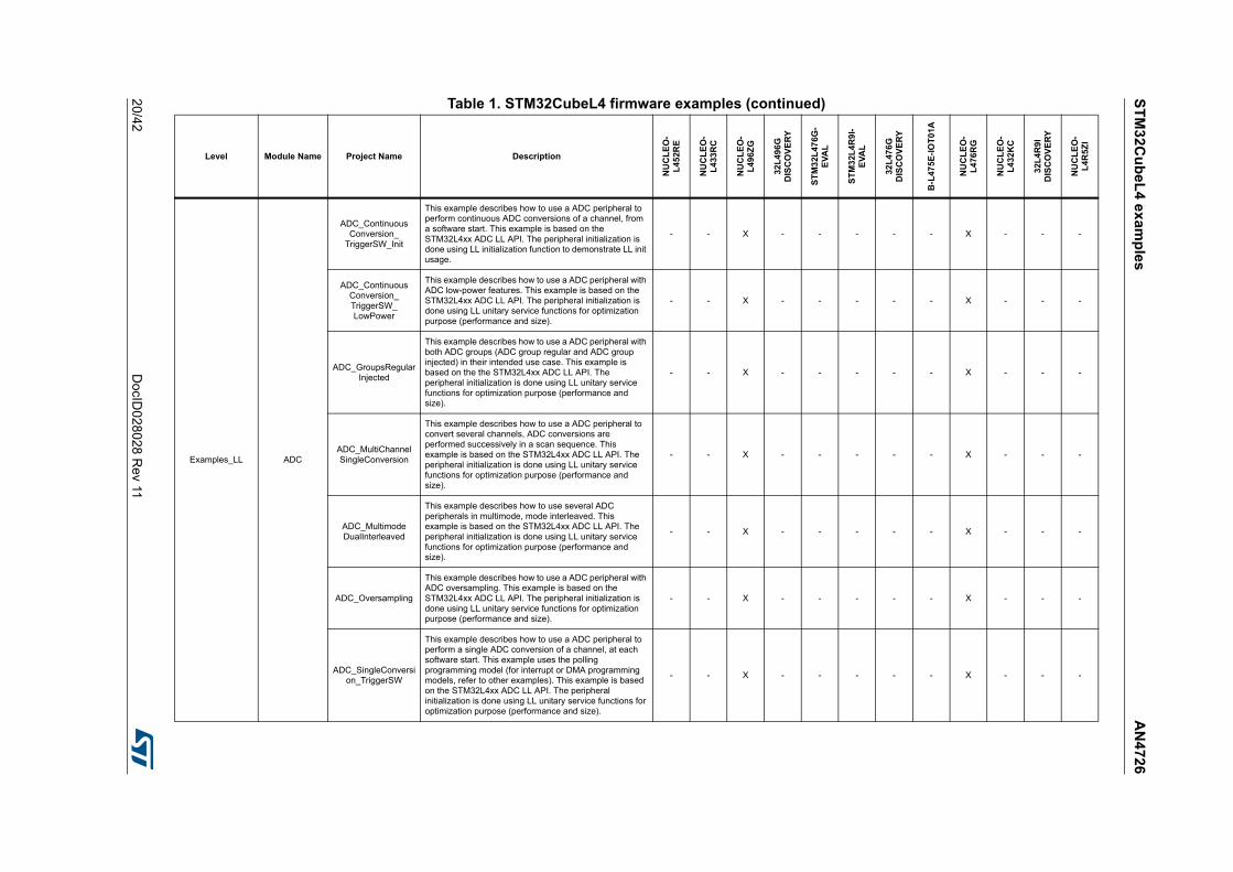
Examples_LL ADC
ADC_ContinuousConversion_
TriggerSW_Init
This example describes how to use a ADC peripheral to perform continuous ADC conversions of a channel, from a software start. This example is based on the STM32L4xx ADC LL API. The peripheral initialization is done using LL initialization function to demonstrate LL init usage.
- - X - - - - - X - - -
ADC_ContinuousConversion_TriggerSW_LowPower
This example describes how to use a ADC peripheral with ADC low-power features. This example is based on the STM32L4xx ADC LL API. The peripheral initialization is done using LL unitary service functions for optimization purpose (performance and size).
- - X - - - - - X - - -
ADC_GroupsRegularInjected
This example describes how to use a ADC peripheral with both ADC groups (ADC group regular and ADC group injected) in their intended use case. This example is based on the the STM32L4xx ADC LL API. The peripheral initialization is done using LL unitary service functions for optimization purpose (performance and size).
- - X - - - - - X - - -
ADC_MultiChannelSingleConversion
This example describes how to use a ADC peripheral to convert several channels, ADC conversions are performed successively in a scan sequence. This example is based on the STM32L4xx ADC LL API. The peripheral initialization is done using LL unitary service functions for optimization purpose (performance and size).
- - X - - - - - X - - -
ADC_MultimodeDualInterleaved
This example describes how to use several ADC peripherals in multimode, mode interleaved. This example is based on the STM32L4xx ADC LL API. The peripheral initialization is done using LL unitary service functions for optimization purpose (performance and size).
- - X - - - - - X - - -
ADC_Oversampling
This example describes how to use a ADC peripheral with ADC oversampling. This example is based on the STM32L4xx ADC LL API. The peripheral initialization is done using LL unitary service functions for optimization purpose (performance and size).
- - X - - - - - X - - -
ADC_SingleConversion_TriggerSW
This example describes how to use a ADC peripheral to perform a single ADC conversion of a channel, at each software start. This example uses the polling programming model (for interrupt or DMA programming models, refer to other examples). This example is based on the STM32L4xx ADC LL API. The peripheral initialization is done using LL unitary service functions for optimization purpose (performance and size).
- - X - - - - - X - - -
Table 1. STM32CubeL4 firmware examples (continued)
Level Module Name Project Name Description
NU
CL
EO
-L
452R
E
NU
CL
EO
-L
433
RC
NU
CL
EO
-L
496Z
G
32L
496
GD
ISC
OV
ER
Y
ST
M3
2L
476G
-E
VA
L
ST
M3
2L4
R9
I-E
VA
L
32L
476
GD
ISC
OV
ER
Y
B-L
475
E-I
OT
01A
NU
CL
EO
-L
476
RG
NU
CL
EO
-L
432
KC
32L
4R
9I
DIS
CO
VE
RY
NU
CL
EO
-L
4R5Z
I

AN
472
6S
TM
32C
ub
eL
4 ex
amp
les
DocID
028028 R
ev 1121
/42
Examples_LL ADC
ADC_SingleConversion_TriggerSW_DMA
This example describes how to use a ADC peripheral to perform a single ADC conversion of a channel, at each software start. This example uses the DMA programming model (for polling or interrupt programming models, refer to other examples). This example is based on the STM32L4xx ADC LL API. The peripheral initialization is done using LL unitary service functions for optimization purpose (performance and size).
- - X - - - - - X - - -
ADC_SingleConversion_TriggerSW_IT
This example describes how to use a ADC peripheral to perform a single ADC conversion of a channel, at each software start. This example uses the interrupt programming model (for polling or DMA programming models, refer to other examples). This example is based on the STM32L4xx ADC LL API. The peripheral initialization is done using LL unitary service functions for optimization purpose (performance and size).
- - X - - - - - X - - -
ADC_SingleConversion_TriggerTimer_DM
A
This example describes how to use a ADC peripheral to perform a single ADC conversion of a channel at each trigger event from timer. Converted data are indefinitely transferred by DMA into a table (circular mode). This example is based on the STM32L4xx ADC LL API. The peripheral initialization is done using LL unitary service functions for optimization purpose (performance and size).
- - X - - - - - X - - -
ADC_TemperatureSensor
This example describes how to use a ADC peripheral to perform a single ADC conversion of the internal temperature sensor and calculate the temperature in Celsius degrees. This example uses the polling programming model (for interrupt or DMA programming models, refer to other examples). This example is based on the STM32L4xx ADC LL API. The peripheral initialization is done using LL unitary service functions for optimization purpose (performance and size).
- - X - - - - - X - - -
Table 1. STM32CubeL4 firmware examples (continued)
Level Module Name Project Name Description
NU
CL
EO
-L
452R
E
NU
CL
EO
-L
433
RC
NU
CL
EO
-L
496Z
G
32L
496
GD
ISC
OV
ER
Y
ST
M3
2L
476G
-E
VA
L
ST
M3
2L4
R9
I-E
VA
L
32L
476
GD
ISC
OV
ER
Y
B-L
475
E-I
OT
01A
NU
CL
EO
-L
476
RG
NU
CL
EO
-L
432
KC
32L
4R
9I
DIS
CO
VE
RY
NU
CL
EO
-L
4R5Z
I
ST
M3
2Cu
be
L4
ex
amp
les
AN
472
6
22/4
2D
ocID028
028 Rev 11
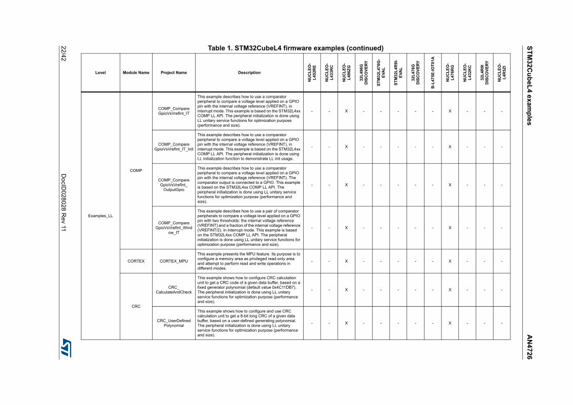
Examples_LL
COMP
COMP_CompareGpioVsVrefInt_IT
This example describes how to use a comparator peripheral to compare a voltage level applied on a GPIO pin with the internal voltage reference (VREFINT), in interrupt mode. This example is based on the STM32L4xx COMP LL API. The peripheral initialization is done using LL unitary service functions for optimization purpose (performance and size).
- - X - - - - - X - - -
COMP_CompareGpioVsVrefInt_IT_Init
This example describes how to use a comparator peripheral to compare a voltage level applied on a GPIO pin with the internal voltage reference (VREFINT), in interrupt mode. This example is based on the STM32L4xx COMP LL API. The peripheral initialization is done using LL initialization function to demonstrate LL init usage.
- - X - - - - - X - - -
COMP_CompareGpioVsVrefInt_
OutputGpio
This example describes how to use a comparator peripheral to compare a voltage level applied on a GPIO pin with the internal voltage reference (VREFINT). The comparator output is connected to a GPIO. This example is based on the STM32L4xx COMP LL API. The peripheral initialization is done using LL unitary service functions for optimization purpose (performance and size).
- - X - - - - - X - - -
COMP_CompareGpioVsVrefInt_Wind
ow_IT
This example describes how to use a pair of comparator peripherals to compare a voltage level applied on a GPIO pin with two thresholds: the internal voltage reference (VREFINT) and a fraction of the internal voltage reference (VREFINT/2), in interrupt mode. This example is based on the STM32L4xx COMP LL API. The peripheral initialization is done using LL unitary service functions for optimization purpose (performance and size).
- - X - - - - - X - - -
CORTEX CORTEX_MPU
This example presents the MPU feature. Its purpose is to configure a memory area as privileged read-only area and attempt to perform read and write operations in different modes.
- - X - - - - - X - - -
CRC
CRC_CalculateAndCheck
This example shows how to configure CRC calculation unit to get a CRC code of a given data buffer, based on a fixed generator polynomial (default value 0x4C11DB7). The peripheral initialization is done using LL unitary service functions for optimization purpose (performance and size).
- - X - - - - - X - - -
CRC_UserDefinedPolynomial
This example shows how to configure and use CRC calculation unit to get a 8-bit long CRC of a given data buffer, based on a user-defined generating polynomial. The peripheral initialization is done using LL unitary service functions for optimization purpose (performance and size).
- - X - - - - - X - - -
Table 1. STM32CubeL4 firmware examples (continued)
Level Module Name Project Name Description
NU
CL
EO
-L
452R
E
NU
CL
EO
-L
433
RC
NU
CL
EO
-L
496Z
G
32L
496
GD
ISC
OV
ER
Y
ST
M3
2L
476G
-E
VA
L
ST
M3
2L4
R9
I-E
VA
L
32L
476
GD
ISC
OV
ER
Y
B-L
475
E-I
OT
01A
NU
CL
EO
-L
476
RG
NU
CL
EO
-L
432
KC
32L
4R
9I
DIS
CO
VE
RY
NU
CL
EO
-L
4R5Z
I

AN
472
6S
TM
32C
ub
eL
4 ex
amp
les
DocID
028028 R
ev 1123
/42
Examples_LL
CRS
CRS_Synchronization_IT
This example describes how to configure Clock Recovery Service in Interrupt mode through the STM32L4xx CRS LL API. The peripheral initialization is done using LL unitary service functions for optimization purpose (performance and size).
- - X - - - - - - - - -
CRS_Synchronization_
Polling
This example describes how to configure Clock Recovery Service in Polling mode through the STM32L4xx CRS LL API. The peripheral initialization is done using LL unitary service functions for optimization purpose (performance and size).
- - X - - - - - - - - -
DAC
DAC_GenerateConstantSignal_
TriggerSW
This example describes how to use the DAC peripheral to generate a constant voltage signal. This example is based on the STM32L4xx DAC LL API. The peripheral initialization is done using LL unitary service functions for optimization purpose (performance and size).
- - X - - - - - X - - -
DAC_GenerateConstantSignal_TriggerSW_LP
This example describes how to use the DAC peripheral to generate a constant voltage signal with DAC low-power sample-and-hold feature. To be effective, a capacitor must be connected to the DAC channel output and the sample-and-hold timings must be tuned depending on the capacitor value. This example is based on the STM32L4xx DAC LL API. The peripheral initialization is done using LL unitary service functions for optimization purpose (performance and size).
- - X - - - - - X - - -
DAC_GenerateWaveform_TriggerHW
This example describes how to use the DAC peripheral to generate a waveform voltage from digital data stream transfered by DMA. This example is based on the STM32L4xx DAC LL API. The peripheral initialization is done using LL unitary service functions for optimization purpose (performance and size).
- - X - - - - - X - - -
DAC_GenerateWaveform_TriggerHW_Init
This example describes how to use the DAC peripheral to generate a waveform voltage from digital data stream transfered by DMA. This example is based on the STM32L4xx DAC LL API. The peripheral initialization is done using LL initialization function to demonstrate LL init usage.
- - X - - - - - X - - -
DMA
DMA_CopyFromFlashToMemory
This example describes how to use a DMA channel to transfer a word data buffer from Flash memory to embedded SRAM. The peripheral initialization is done using LL unitary service functions for optimization purpose (performance and size).
- - X - - - - - X - - -
DMA_CopyFromFlashToMemory_Init
This example describes how to use a DMA channel to transfer a word data buffer from Flash memory to embedded SRAM. The peripheral initialization is done using LL initialization function to demonstrate LL init usage.
- - X - - - - - X - - -
Table 1. STM32CubeL4 firmware examples (continued)
Level Module Name Project Name Description
NU
CL
EO
-L
452R
E
NU
CL
EO
-L
433
RC
NU
CL
EO
-L
496Z
G
32L
496
GD
ISC
OV
ER
Y
ST
M3
2L
476G
-E
VA
L
ST
M3
2L4
R9
I-E
VA
L
32L
476
GD
ISC
OV
ER
Y
B-L
475
E-I
OT
01A
NU
CL
EO
-L
476
RG
NU
CL
EO
-L
432
KC
32L
4R
9I
DIS
CO
VE
RY
NU
CL
EO
-L
4R5Z
I
ST
M3
2Cu
be
L4
ex
amp
les
AN
472
6
24/4
2D
ocID028
028 Rev 11
Examples_LL
DMA2DDMA2D_
MemoryToMemory
This example describes how to configure the DMA2D peripheral in Memory-to-Memory transfer mode. The example is based on the STM32L4xx DMA2D LL API. The peripheral initialization is done using LL unitary service functions for optimization purpose (performance and size).
- - - X - - - - - - - -
EXTI
EXTI_ToggleLedOnIT
This example describes how to configure the EXTI and use GPIOs to toggle the user LEDs available on the board when a user button is pressed. It is based on the STM32L4xx LL API. The peripheral initialization is done using LL unitary services functions for optimization purpose (performance and size).
- - X - - - - - X - - -
EXTI_ToggleLedOnIT_Init
This example describes how to configure the EXTI and use GPIOs to toggle the user LEDs available on the board when a user button is pressed. This example is based on the STM32L4xx LL API. The peripheral initialization is done using LL initialization function to demonstrate LL init usage.
- - X - - - - - X - - -
GPIO
GPIO_InfiniteLedToggling
This example describes how to configure and use GPIOs to toggle every 250 ms the user LEDs available on the board. This example is based on the STM32L4xx LL API. The peripheral initialization is done using LL unitary service functions for optimization purpose (performance and size).
- - X - - - - - X - - -
GPIO_InfiniteLedToggling_
Init
This example describes how to configure and use GPIOs to toggle every 250 ms the user LEDs available on the board. This example is based on the STM32L4xx LL API. The peripheral initialization is done using LL initialization function to demonstrate LL init usage.
- - X - - - - - X - - -
I2C
I2C_OneBoard_AdvCommunication_
DMAAndIT
This example describes how to exchange data between an I2C Master device in DMA mode and an I2C Slave device in Interrupt mode. The peripheral initialization is done using LL unitary services functions for optimization purpose (performance and size).
- - X - - - - - X - - -
I2C_OneBoard_Communication_
DMAAndIT
This example describes how to transmit data bytes from an I2C Master device using DMA mode to an I2C Slave device using Interrupt mode. The peripheral initialization is done using LL unitary service functions for optimization purpose (performance and size).
- - X - - - - - X - - -
I2C_OneBoard_Communication_IT
This example describes how to receive one data byte from an I2C Slave device to an I2C Master device. Both devices operate in Interrupt mode. The peripheral initialization is done using LL unitary service functions for optimization purpose (performance and size).
- - X - - - - - X - - -
Table 1. STM32CubeL4 firmware examples (continued)
Level Module Name Project Name Description
NU
CL
EO
-L
452R
E
NU
CL
EO
-L
433
RC
NU
CL
EO
-L
496Z
G
32L
496
GD
ISC
OV
ER
Y
ST
M3
2L
476G
-E
VA
L
ST
M3
2L4
R9
I-E
VA
L
32L
476
GD
ISC
OV
ER
Y
B-L
475
E-I
OT
01A
NU
CL
EO
-L
476
RG
NU
CL
EO
-L
432
KC
32L
4R
9I
DIS
CO
VE
RY
NU
CL
EO
-L
4R5Z
I
AN
472
6S
TM
32C
ub
eL
4 ex
amp
les
DocID
028028 R
ev 1125
/42
Examples_LL
I2C
I2C_OneBoard_Communication_IT_
Init
This example describes how to receive one data byte from an I2C Slave device to an I2C Master device. Both devices operate in Interrupt mode. The peripheral initialization is done using LL initialization function to demonstrate LL init usage.
- - X - - - - - X - - -
I2C_OneBoard_Communication_
PollingAndIT
This example describes how to transmit data bytes from an I2C Master device using Polling mode to an I2C Slave device using Interrupt mode. The peripheral initialization is done using LL unitary service functions for optimization purpose (performance and size).
- - X - - - - - X - - -
I2C_TwoBoards_MasterRx_SlaveTx_
IT
This example describes how to receive one data byte from an I2C Slave device to an I2C Master device. Both devices operate in Interrupt mode. The peripheral initialization is done using LL unitary service functions for optimization purpose (performance and size).
- - X - - - - - X - - -
I2C_TwoBoards_MasterTx_SlaveRx
This example describes how to transmit data bytes from an I2C Master device using Polling mode to an I2C Slave device using Interrupt mode. The peripheral initialization is done using LL unitary service functions for optimization purpose (performance and size).
- - X - - - - - X - - -
I2C_TwoBoards_MasterTx_SlaveRx_
DMA
This example describes how to transmit data bytes from an I2C Master device using DMA mode to an I2C Slave device using DMA mode. The peripheral initialization is done using LL unitary services functions for optimization purpose (performance and size).
- - X - - - - - X - - -
I2C_TwoBoards_WakeUpFromStop2_
IT
This example describes how to receive data byte from an I2C Slave device in Stop2 mode using Interrupt mode to an I2C Master device Interrupt mode. The peripheral initialization is done using LL unitary service functions for optimization purpose (performance and size).
- - X - - - - - X - - -
IWDGIWDG_RefreshUntilUserEvent
This example describes how to configure the IWDG to ensure periodic counter update and generate an MCU IWDG reset when a user button is pressed. The peripheral initialization is done using LL unitary service functions for optimization purpose (performance and size).
- - X - - - - - X - - -
LPTIM
LPTIM_PulseCounter
This example describes how to use the LPTIM in counter mode to generate a PWM output signal and update PWM duty cycle. This example is based on the STM32L4xx LPTIM LL API. The peripheral initialization is done using LL unitary service functions for optimization purpose (performance and size).
- - X - - - - - X - - -
LPTIM_PulseCounter_Init
This example describes how to use the LPTIM in counter mode to generate a PWM output signal and update PWM duty cycle. This example is based on the STM32L4xx LPTIM LL API. The peripheral initialization is done using LL initialization function to demonstrate LL init usage.
- - X - - - - - X - - -
Table 1. STM32CubeL4 firmware examples (continued)
Level Module Name Project Name Description
NU
CL
EO
-L
452R
E
NU
CL
EO
-L
433
RC
NU
CL
EO
-L
496Z
G
32L
496
GD
ISC
OV
ER
Y
ST
M3
2L
476G
-E
VA
L
ST
M3
2L4
R9
I-E
VA
L
32L
476
GD
ISC
OV
ER
Y
B-L
475
E-I
OT
01A
NU
CL
EO
-L
476
RG
NU
CL
EO
-L
432
KC
32L
4R
9I
DIS
CO
VE
RY
NU
CL
EO
-L
4R5Z
I

ST
M3
2Cu
be
L4
ex
amp
les
AN
472
6
26/4
2D
ocID028
028 Rev 11
Examples_LL
LPUART
LPUART_WakeUpFromStop2
This example shows how to configure GPIO and LPUART peripherals to allow characters received on LPUART RX pin to wake up the MCU from low-power mode. This example is based on the STM32L4xx LPUART LL API. The peripheral initialization is done using LL unitary services functions for optimization purpose (performance and size).
- - X - - - - - X - - -
LPUART_WakeUpFromStop2_
Init
This example shows how to configure GPIO and LPUART peripherals to allow characters received on LPUART RX pin to wake up the MCU from low-power mode. This example is based on the STM32L4xx LPUART LL API. The peripheral initialization is done using LL initialization function to demonstrate LL init usage.
- - X - - - - - X - - -
OPAMP
OPAMP_PGA
This example describes how to use a operational amplifier peripheral in PGA mode (programmable gain amplifier). To test the OPAMP, a voltage waveform is generated by the DAC and feeds the OPAMP input. This example is based on the STM32L4xx OPAMP LL API. The peripheral initialization is done using LL unitary service functions for optimization purpose (performance and size).
- - X - - - - - X - - -
OPAMP_PGA_Init
This example describes how to use a operational amplifier peripheral in PGA mode (programmable gain amplifier). To test the OPAMP, a voltage waveform is generated by the DAC and feeds the OPAMP input. This example is based on the STM32L4xx OPAMP LL API. The peripheral initialization is done using LL initialization function to demonstrate LL init usage.
- - X - - - - - X - - -
PWR
PWR_EnterStandbyMode
This example shows how to enter Standby mode and wake up from this mode using an external reset or a wakeup interrupt.
- - X - - - - - X - - -
PWR_EnterStopMode
This example shows how to enter Stop 2 mode. - - X - - - - - X - - -
PWR_LPRunMode_SRAM1
This example shows how to execute code in Low-power run mode from SRAM1.
- - X - - - - - X - - -
PWR_OptimizedRunMode
This example shows how to increase/decrease frequency and VCORE and how to enter/exit Low-power run mode.
- - X - - - - - X - - -
Table 1. STM32CubeL4 firmware examples (continued)
Level Module Name Project Name Description
NU
CL
EO
-L
452R
E
NU
CL
EO
-L
433
RC
NU
CL
EO
-L
496Z
G
32L
496
GD
ISC
OV
ER
Y
ST
M3
2L
476G
-E
VA
L
ST
M3
2L4
R9
I-E
VA
L
32L
476
GD
ISC
OV
ER
Y
B-L
475
E-I
OT
01A
NU
CL
EO
-L
476
RG
NU
CL
EO
-L
432
KC
32L
4R
9I
DIS
CO
VE
RY
NU
CL
EO
-L
4R5Z
I
AN
472
6S
TM
32C
ub
eL
4 ex
amp
les
DocID
028028 R
ev 1127
/42
Examples_LL
RCC
RCC_HWAutoMSICalibration
This example demonstrates and explains how to use the MSI clock source hardware auto-calibration to get an accurate MSI clock using LSE (PLL mode).
- - X - - - - - X - - -
RCC_OutputSystemClockOnMCO
This example describes how to configure MCO pin (PA8) to output the system clock.
- - X - - - - - X - - -
RCC_UseHSEasSystemClock
This example describes how to use the RCC LL API to start the HSE and use it as system clock.
- - X - - - - - X - - -
RCC_UseHSI_PLLasSystemClock
This example shows how to modify the PLL parameters in run time.
- - X - - - - - X - - -
RNG
RNG_GenerateRandomNumbers
This example shows how to configure the RNG peripheral to generate 32-bit long random numbers. The peripheral initialization is done using LL unitary service functions for optimization purpose (performance and size).
- - X - - - - - X - - -
RNG_GenerateRandomNumbers_IT
This example shows how to configure the RNG peripheral to generate 32-bit long random numbers using interrupts. The peripheral initialization is done using LL unitary service functions for optimization purpose (performance and size).
- - X - - - - - X - - -
Table 1. STM32CubeL4 firmware examples (continued)
Level Module Name Project Name Description
NU
CL
EO
-L
452R
E
NU
CL
EO
-L
433
RC
NU
CL
EO
-L
496Z
G
32L
496
GD
ISC
OV
ER
Y
ST
M3
2L
476G
-E
VA
L
ST
M3
2L4
R9
I-E
VA
L
32L
476
GD
ISC
OV
ER
Y
B-L
475
E-I
OT
01A
NU
CL
EO
-L
476
RG
NU
CL
EO
-L
432
KC
32L
4R
9I
DIS
CO
VE
RY
NU
CL
EO
-L
4R5Z
I
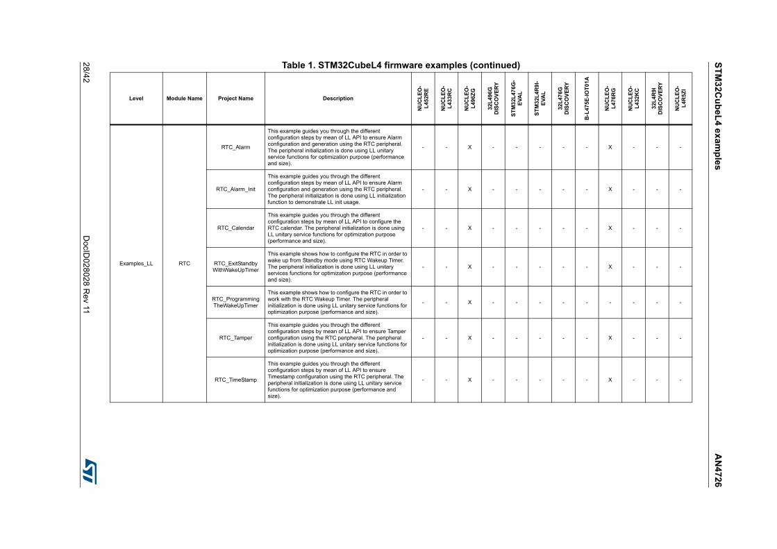
ST
M3
2Cu
be
L4
ex
amp
les
AN
472
6
28/4
2D
ocID028
028 Rev 11
Examples_LL RTC
RTC_Alarm
This example guides you through the different configuration steps by mean of LL API to ensure Alarm configuration and generation using the RTC peripheral. The peripheral initialization is done using LL unitary service functions for optimization purpose (performance and size).
- - X - - - - - X - - -
RTC_Alarm_Init
This example guides you through the different configuration steps by mean of LL API to ensure Alarm configuration and generation using the RTC peripheral. The peripheral initialization is done using LL initialization function to demonstrate LL init usage.
- - X - - - - - X - - -
RTC_Calendar
This example guides you through the different configuration steps by mean of LL API to configure the RTC calendar. The peripheral initialization is done using LL unitary service functions for optimization purpose (performance and size).
- - X - - - - - X - - -
RTC_ExitStandbyWithWakeUpTimer
This example shows how to configure the RTC in order to wake up from Standby mode using RTC Wakeup Timer. The peripheral initialization is done using LL unitary services functions for optimization purpose (performance and size).
- - X - - - - - X - - -
RTC_ProgrammingTheWakeUpTimer
This example shows how to configure the RTC in order to work with the RTC Wakeup Timer. The peripheral initialization is done using LL unitary service functions for optimization purpose (performance and size).
- - X - - - - - - - - -
RTC_Tamper
This example guides you through the different configuration steps by mean of LL API to ensure Tamper configuration using the RTC peripheral. The peripheral initialization is done using LL unitary service functions for optimization purpose (performance and size).
- - X - - - - - X - - -
RTC_TimeStamp
This example guides you through the different configuration steps by mean of LL API to ensure Timestamp configuration using the RTC peripheral. The peripheral initialization is done using LL unitary service functions for optimization purpose (performance and size).
- - X - - - - - X - - -
Table 1. STM32CubeL4 firmware examples (continued)
Level Module Name Project Name Description
NU
CL
EO
-L
452R
E
NU
CL
EO
-L
433
RC
NU
CL
EO
-L
496Z
G
32L
496
GD
ISC
OV
ER
Y
ST
M3
2L
476G
-E
VA
L
ST
M3
2L4
R9
I-E
VA
L
32L
476
GD
ISC
OV
ER
Y
B-L
475
E-I
OT
01A
NU
CL
EO
-L
476
RG
NU
CL
EO
-L
432
KC
32L
4R
9I
DIS
CO
VE
RY
NU
CL
EO
-L
4R5Z
I

AN
472
6S
TM
32C
ub
eL
4 ex
amp
les
DocID
028028 R
ev 1129
/42
Examples_LL
SPI
SPI_OneBoard_HalfDuplex_DMA
This example shows how to configure GPIO and SPI peripherals to transmit bytes from an SPI Master device to an SPI Slave device in DMA mode. The example is based on the STM32L4xx SPI LL API. The peripheral initialization is done using LL unitary service functions for optimization purpose (performance and size).
- - X - - - - - X - - -
SPI_OneBoard_HalfDuplex_DMA_Init
This example shows how to configure GPIO and SPI peripherals to transmit bytes from an SPI Master device to an SPI Slave device in DMA mode. The example is based on the STM32L4xx SPI LL API. The peripheral initialization is done using LL initialization function to demonstrate LL init usage.
- - X - - - - - X - - -
SPI_OneBoard_HalfDuplex_IT
This example shows how to configure GPIO and SPI peripherals to transmit bytes from an SPI Master device to an SPI Slave device in Interrupt mode. The example is based on the STM32L4xx SPI LL API. The peripheral initialization is done using LL unitary service functions for optimization purpose (performance and size).
- - X - - - - - X - - -
SPI_TwoBoards_FullDuplex_DMA
This example shows how to ensure SPI data buffer transmission and reception in DMA mode. The example is based on the STM32L4xx SPI LL API. The peripheral initialization is done using LL unitary service functions for optimization purpose (performance and size).
- - X - - - - - X - - -
SPI_TwoBoards_FullDuplex_IT
This example shows how to ensure SPI Data buffer transmission and reception in Interrupt mode. The example is based on the STM32L4xx SPI LL API. The peripheral initialization is done using LL unitary service functions for optimization purpose (performance and size).
- - X - - - - - X - - -
SWPMI
SWPMI_Loopback_MultiSWBuffer
This example describes how to configure the SWPMI peripheral to start a communication using DMA multibuffers in Loopback mode. The peripheral initialization is done using LL unitary service functions for optimization purpose (performance and size).
- - X - - - - - X - - -
SWPMI_Loopback_MultiSWBuffer_Init
This example describes how to configure the SWPMI peripheral to start a communication using DMA multibuffers in Loopback mode. The peripheral initialization is done using LL initialization function to demonstrate LL init usage.
- - X - - - - - X - - -
SWPMI_Loopback_NoSWBuffer
This example describes how to configure the SWPMI peripheral to start a communication using No software buffer mode in Loopback mode. The peripheral initialization is done using LL unitary service functions for optimization purpose (performance and size).
- - X - - - - - X - - -
Table 1. STM32CubeL4 firmware examples (continued)
Level Module Name Project Name Description
NU
CL
EO
-L
452R
E
NU
CL
EO
-L
433
RC
NU
CL
EO
-L
496Z
G
32L
496
GD
ISC
OV
ER
Y
ST
M3
2L
476G
-E
VA
L
ST
M3
2L4
R9
I-E
VA
L
32L
476
GD
ISC
OV
ER
Y
B-L
475
E-I
OT
01A
NU
CL
EO
-L
476
RG
NU
CL
EO
-L
432
KC
32L
4R
9I
DIS
CO
VE
RY
NU
CL
EO
-L
4R5Z
I
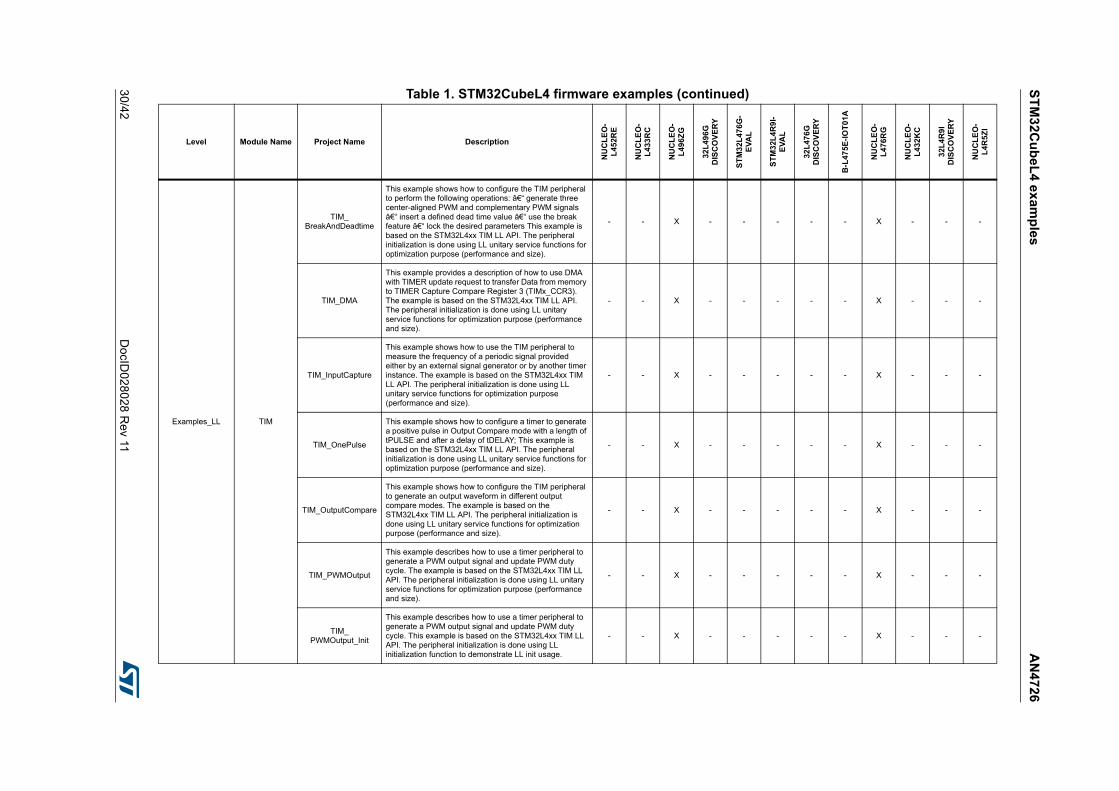
ST
M3
2Cu
be
L4
ex
amp
les
AN
472
6
30/4
2D
ocID028
028 Rev 11
Examples_LL TIM
TIM_BreakAndDeadtime
This example shows how to configure the TIM peripheral to perform the following operations: – generate three center-aligned PWM and complementary PWM signals – insert a defined dead time value – use the break feature – lock the desired parameters This example is based on the STM32L4xx TIM LL API. The peripheral initialization is done using LL unitary service functions for optimization purpose (performance and size).
- - X - - - - - X - - -
TIM_DMA
This example provides a description of how to use DMA with TIMER update request to transfer Data from memory to TIMER Capture Compare Register 3 (TIMx_CCR3). The example is based on the STM32L4xx TIM LL API. The peripheral initialization is done using LL unitary service functions for optimization purpose (performance and size).
- - X - - - - - X - - -
TIM_InputCapture
This example shows how to use the TIM peripheral to measure the frequency of a periodic signal provided either by an external signal generator or by another timer instance. The example is based on the STM32L4xx TIM LL API. The peripheral initialization is done using LL unitary service functions for optimization purpose (performance and size).
- - X - - - - - X - - -
TIM_OnePulse
This example shows how to configure a timer to generate a positive pulse in Output Compare mode with a length of tPULSE and after a delay of tDELAY; This example is based on the STM32L4xx TIM LL API. The peripheral initialization is done using LL unitary service functions for optimization purpose (performance and size).
- - X - - - - - X - - -
TIM_OutputCompare
This example shows how to configure the TIM peripheral to generate an output waveform in different output compare modes. The example is based on the STM32L4xx TIM LL API. The peripheral initialization is done using LL unitary service functions for optimization purpose (performance and size).
- - X - - - - - X - - -
TIM_PWMOutput
This example describes how to use a timer peripheral to generate a PWM output signal and update PWM duty cycle. The example is based on the STM32L4xx TIM LL API. The peripheral initialization is done using LL unitary service functions for optimization purpose (performance and size).
- - X - - - - - X - - -
TIM_PWMOutput_Init
This example describes how to use a timer peripheral to generate a PWM output signal and update PWM duty cycle. This example is based on the STM32L4xx TIM LL API. The peripheral initialization is done using LL initialization function to demonstrate LL init usage.
- - X - - - - - X - - -
Table 1. STM32CubeL4 firmware examples (continued)
Level Module Name Project Name Description
NU
CL
EO
-L
452R
E
NU
CL
EO
-L
433
RC
NU
CL
EO
-L
496Z
G
32L
496
GD
ISC
OV
ER
Y
ST
M3
2L
476G
-E
VA
L
ST
M3
2L4
R9
I-E
VA
L
32L
476
GD
ISC
OV
ER
Y
B-L
475
E-I
OT
01A
NU
CL
EO
-L
476
RG
NU
CL
EO
-L
432
KC
32L
4R
9I
DIS
CO
VE
RY
NU
CL
EO
-L
4R5Z
I
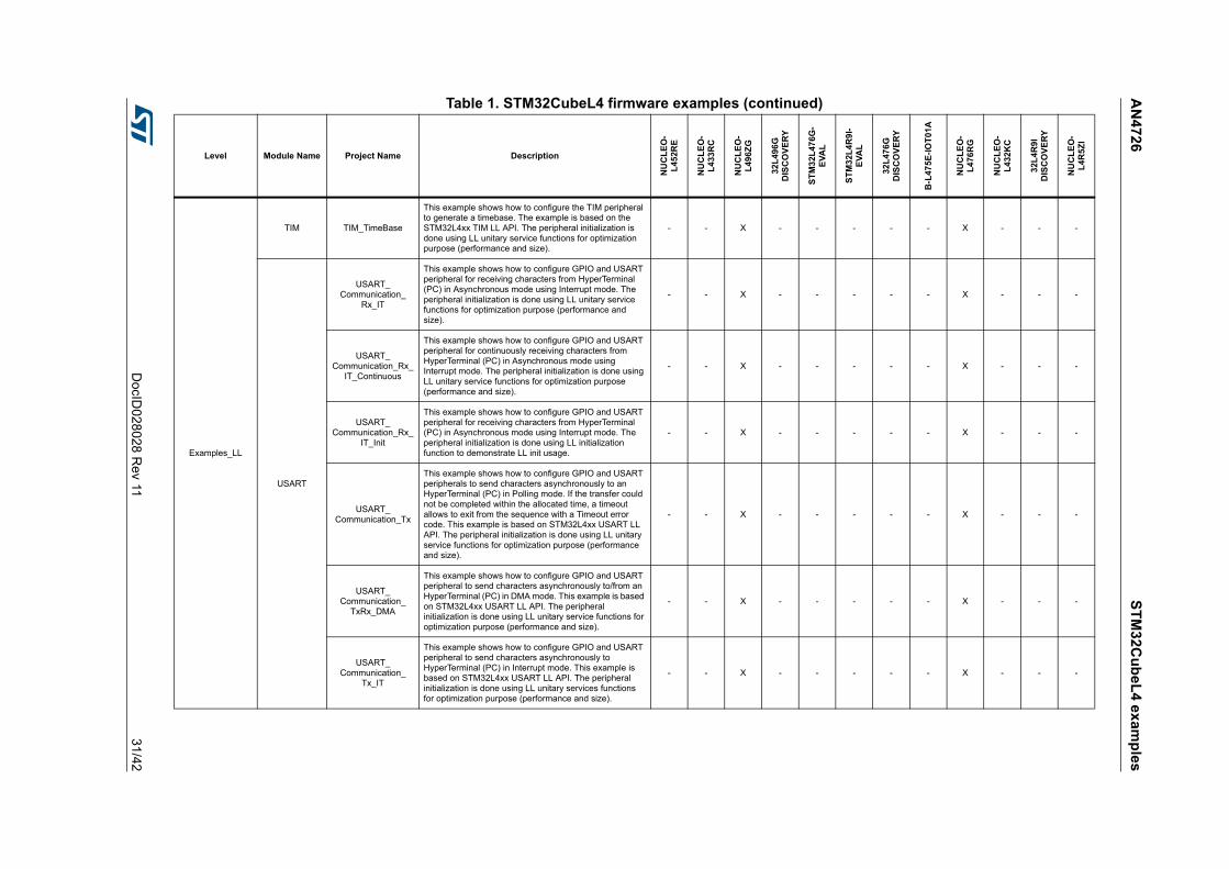
AN
472
6S
TM
32C
ub
eL
4 ex
amp
les
DocID
028028 R
ev 1131
/42
Examples_LL
TIM TIM_TimeBase
This example shows how to configure the TIM peripheral to generate a timebase. The example is based on the STM32L4xx TIM LL API. The peripheral initialization is done using LL unitary service functions for optimization purpose (performance and size).
- - X - - - - - X - - -
USART
USART_Communication_
Rx_IT
This example shows how to configure GPIO and USART peripheral for receiving characters from HyperTerminal (PC) in Asynchronous mode using Interrupt mode. The peripheral initialization is done using LL unitary service functions for optimization purpose (performance and size).
- - X - - - - - X - - -
USART_Communication_Rx_
IT_Continuous
This example shows how to configure GPIO and USART peripheral for continuously receiving characters from HyperTerminal (PC) in Asynchronous mode using Interrupt mode. The peripheral initialization is done using LL unitary service functions for optimization purpose (performance and size).
- - X - - - - - X - - -
USART_Communication_Rx_
IT_Init
This example shows how to configure GPIO and USART peripheral for receiving characters from HyperTerminal (PC) in Asynchronous mode using Interrupt mode. The peripheral initialization is done using LL initialization function to demonstrate LL init usage.
- - X - - - - - X - - -
USART_Communication_Tx
This example shows how to configure GPIO and USART peripherals to send characters asynchronously to an HyperTerminal (PC) in Polling mode. If the transfer could not be completed within the allocated time, a timeout allows to exit from the sequence with a Timeout error code. This example is based on STM32L4xx USART LL API. The peripheral initialization is done using LL unitary service functions for optimization purpose (performance and size).
- - X - - - - - X - - -
USART_Communication_
TxRx_DMA
This example shows how to configure GPIO and USART peripheral to send characters asynchronously to/from an HyperTerminal (PC) in DMA mode. This example is based on STM32L4xx USART LL API. The peripheral initialization is done using LL unitary service functions for optimization purpose (performance and size).
- - X - - - - - X - - -
USART_Communication_
Tx_IT
This example shows how to configure GPIO and USART peripheral to send characters asynchronously to HyperTerminal (PC) in Interrupt mode. This example is based on STM32L4xx USART LL API. The peripheral initialization is done using LL unitary services functions for optimization purpose (performance and size).
- - X - - - - - X - - -
Table 1. STM32CubeL4 firmware examples (continued)
Level Module Name Project Name Description
NU
CL
EO
-L
452R
E
NU
CL
EO
-L
433
RC
NU
CL
EO
-L
496Z
G
32L
496
GD
ISC
OV
ER
Y
ST
M3
2L
476G
-E
VA
L
ST
M3
2L4
R9
I-E
VA
L
32L
476
GD
ISC
OV
ER
Y
B-L
475
E-I
OT
01A
NU
CL
EO
-L
476
RG
NU
CL
EO
-L
432
KC
32L
4R
9I
DIS
CO
VE
RY
NU
CL
EO
-L
4R5Z
I

ST
M3
2Cu
be
L4
ex
amp
les
AN
472
6
32/4
2D
ocID028
028 Rev 11
Examples_LL
USART
USART_HardwareFlow
Control
This example shows how to configure GPIO and USART peripheral to receive characters asynchronously from HyperTerminal (PC) in Interrupt mode with Hardware Flow Control feature enabled. This example is based on STM32L4xx USART LL API. The peripheral initialization is done using LL unitary service functions for optimization purpose (performance and size).
- - X - - - - - X - - -
USART_SyncCommunication_FullDuplex
_DMA
This example shows how to configure GPIO, USART, DMA and SPI peripherals to transmit bytes from/to a USART peripheral to/from a SPI peripheral (in slave mode) by using DMA mode through the STM32L4xx USART LL API. The peripheral initialization is done using LL unitary service functions for optimization purpose (performance and size).
- - X - - - - - X - - -
USART_SyncCommunication_FullDuplex
_IT
This example shows how to configure GPIO, USART, DMA and SPI peripherals to transmit bytes from/to a USART peripheral to/from a SPI peripheral (in slave mode) by using Interrupt mode through the STM32L4xx USART LL API (the SPI uses the DMA to receive/transmit characters sent from/received by the USART). The peripheral initialization is done using LL unitary service functions for optimization purpose (performance and size).
- - X - - - - - X - - -
USART_WakeUpFromStop1
This example shows how to configure GPIO and USART peripherals to receive characters on USART RX pin and wake up the MCU from low-power mode, using STM32L4xx USART LL API. The peripheral initialization is done using LL unitary service functions for optimization purpose (performance and size).
- - X - - - - - X - - -
UTILS
UTILS_ConfigureSystem
Clock
This example describes how to use UTILS LL API to configure the system clock using PLL with HSI as source clock. The user application just needs to calculate PLL parameters using STM32CubeMX and call the UTILS LL API.
- - X - - - - - X - - -
UTILS_ReadDeviceInfo
This example describes how to read UID, Device ID and Revision ID and save them into a global information buffer.
- - X - - - - - X - - -
WWDGWWDG_RefreshUntil
UserEvent
This example describes how to configure the WWDG, periodically update the counter, and generate an MCU WWDG reset when a user button is pressed. The peripheral initialization is done using LL unitary service functions for optimization purpose (performance and size).
- - X - - - - - X - - -
Total number of examples_ll: 186 0 0 94 1 0 0 0 0 91 0 0 0
Table 1. STM32CubeL4 firmware examples (continued)
Level Module Name Project Name Description
NU
CL
EO
-L
452R
E
NU
CL
EO
-L
433
RC
NU
CL
EO
-L
496Z
G
32L
496
GD
ISC
OV
ER
Y
ST
M3
2L
476G
-E
VA
L
ST
M3
2L4
R9
I-E
VA
L
32L
476
GD
ISC
OV
ER
Y
B-L
475
E-I
OT
01A
NU
CL
EO
-L
476
RG
NU
CL
EO
-L
432
KC
32L
4R
9I
DIS
CO
VE
RY
NU
CL
EO
-L
4R5Z
I

AN
472
6S
TM
32C
ub
eL
4 ex
amp
les
DocID
028028 R
ev 1133
/42
Examples_MIX
ADCADC_
SingleConversion_TriggerSW_IT
This example describes how to use the ADC to perform a single ADC channel conversion at each software start. This example uses the interrupt programming model (for Polling or DMA programming models, refer to other examples). This example is based on the STM32L4xx ADC HAL and LL API. The LL API is used for performance improvement.
- - - - - - - - X - - -
CRCCRC_
PolynomialUpdate
This example provides a description of how to use the CRC peripheral through the STM32L4xx CRC HAL and LL API. The LL API is used for performance improvement.
- - X - - - - - X - - -
DMA DMA_FLASHToRAM
This example provides a description of how to use a DMA to transfer a word data buffer from Flash memory to embedded SRAM through the STM32L4xx DMA HAL and LL API. The LL API is used for performance improvement.
- - X - - - - - X - - -
DMA2D
DMA2D_MemToMemWithLCD
This example provides a description of how to configure the DMA2D peripheral in Memory_to_Memory transfer mode and display the result on LCD, in resorting to DMA2D LL APIs for performance improvement.
- - - X - - - - - - - -
DMA2D_MemToMemWithRBSwap
This example provides a description of how to configure DMA2D peripheral in Memory to Memory transfer mode with Pixel Format Conversion and images blending then display the result on LCD, in resorting to DMA2D LL APIs for performance improvement.
- - - X - - - - - - - -
I2CI2C_OneBoard_
ComSlave7_10bits_IT
This example describes how to perform I2C data buffer transmission/reception between one master and 2 slaves with different address sizes (7-bit or 10-bit). This example uses the STM32L4xx I2C HAL and LL API (LL API usage for performance improvement) and an interrupt.
- - X - - - - - X - - -
OPAMPOPAMP_
CALIBRATION
This example describes how to use an operational amplifier peripheral with OPAMP calibration and operation. This example is based on the STM32L4xx OPAMP HAL and LL API (LL API used for performance improvement).
- - - - - - - - X - - -
PWR
PWR_STANDBY_RTC
This example shows how to enter Standby mode and wake up from this mode using an external reset or the RTC wakeup timer through the STM32L4xx RTC and RCC HAL and LL API. The LL API is used for performance improvement.
- - X - - - - - X - - -
PWR_STOP1
This example shows how to enter the system in Stop 1 mode and wake up from this mode using external reset or wakeup interrupt (all the RCC functions calls use RCC LL API for footprint and performance improvements).
- - X - - - - - X - - -
Table 1. STM32CubeL4 firmware examples (continued)
Level Module Name Project Name Description
NU
CL
EO
-L
452R
E
NU
CL
EO
-L
433
RC
NU
CL
EO
-L
496Z
G
32L
496
GD
ISC
OV
ER
Y
ST
M3
2L
476G
-E
VA
L
ST
M3
2L4
R9
I-E
VA
L
32L
476
GD
ISC
OV
ER
Y
B-L
475
E-I
OT
01A
NU
CL
EO
-L
476
RG
NU
CL
EO
-L
432
KC
32L
4R
9I
DIS
CO
VE
RY
NU
CL
EO
-L
4R5Z
I

ST
M3
2Cu
be
L4
ex
amp
les
AN
472
6
34/4
2D
ocID028
028 Rev 11
Examples_MIX
SPI
SPI_FullDuplex_ComPolling
This example shows how to ensure SPI data buffer transmission/reception in Polling mode between two boards.
- - X - - - - - X - - -
SPI_HalfDuplex_ComPollingIT
This example shows how to ensure SPI data buffer transmission/reception between two boards by using Polling (LL Driver) an interrupt mode (HAL Driver).
- - X - - - - - X - - -
TIM TIM_6Steps
This example shows how to configure the TIM1 peripheral to generate six-step PWM signal. The STM32L4xx TIM1 peripheral allows programming in advance the configuration for the next TIM1 output behavior (or step) and changing the configuration of all the channels simultaneously. This operation is possible when the COM (commutation) event is used. This example is based on the STM32L4xx TIM HAL and LL API. The LL API is used for performance improvement.
- - X - - - - - X - - -
UART
UART_HyperTerminal_IT
This example describes how to use an UART to transmit data (transmit/receive) between a board and an HyperTerminal PC application in Interrupt mode. This example provides a description of how to use USART peripheral through the STM32L4xx UART HAL and LL API. The LL API is used for performance improvement.
- - X - - - - - X - - -
UART_HyperTerminal_TxPolling_RxIT
This example describes how to use an UART to transmit data (transmit/receive) between a board and an HyperTerminal PC application both in Polling and Interrupt modes. This example provides a description of how to use USART peripheral through the STM32L4xx UART HAL and LL API. The LL API is used for performance improvement.
- - X - - - - - X - - -
Total number of examples_mix: 24 0 0 10 2 0 0 0 0 12 0 0 0
Applications
- ProximityThis application shows how to use the VL53L0X sensor mounted on the B-L475E-IOT01A board to provide proximity information.
- - - - - - - X - - - -
BLE
HeartRateThis application shows how to use BLE component for HeartRate profile application.
- - - - - - - X - - - -
P2P_LedButtonThis example aims at demonstrating point-to-point communications using the BLE component.
- - - - - - - X - - - -
Table 1. STM32CubeL4 firmware examples (continued)
Level Module Name Project Name Description
NU
CL
EO
-L
452R
E
NU
CL
EO
-L
433
RC
NU
CL
EO
-L
496Z
G
32L
496
GD
ISC
OV
ER
Y
ST
M3
2L
476G
-E
VA
L
ST
M3
2L4
R9
I-E
VA
L
32L
476
GD
ISC
OV
ER
Y
B-L
475
E-I
OT
01A
NU
CL
EO
-L
476
RG
NU
CL
EO
-L
432
KC
32L
4R
9I
DIS
CO
VE
RY
NU
CL
EO
-L
4R5Z
I

AN
472
6S
TM
32C
ub
eL
4 ex
amp
les
DocID
028028 R
ev 1135
/42
Applications FatFs
FatFs_RAMDisk
This application provides a description on how to use STM32Cube firmware with FatFs middleware component as a generic FAT file system module. The objective is to develop an application that exploits the FatFs features to configure a RAM disk (SRAM) drive.
- - - - X - - - - - - -
FatFs_USBDisk_Standalone
This application provides a description on how to use STM32Cube firmware with FatFs middleware component as a generic FAT file system module and STM32 USB On-The-Go (OTG) host library, in Full Speed (FS) mode in order to develop an application exploiting FatFs offered features with USB disk drive configuration.
- - - - - New - - - - - -
FatFs_uSD_DMA_RTOS
This application provides a description on how to use STM32Cube firmware with FatFs middleware component as a generic FAT file system module, in order to develop an application exploiting FatFs offered features with microSD drive in RTOS mode configuration.
- - - X X New - - - - - -
FatFs_uSD_DMA_Standalone
This application provides a description on how to use STM32Cube firmware with FatFs middleware component as a generic FAT file system module. The objective is to develop an application making the most of the features offered by FatFs to configure a microSD drive.
- - - - - New - - - - - -
FatFs_uSD_Standalone
This application provides a description on how to use STM32Cube firmware with FatFs middleware component as a generic FAT file system module. The objective is to develop an application that exploits the FatFs features to configure a microSD drive.
- - - X X New - - - - New -
Table 1. STM32CubeL4 firmware examples (continued)
Level Module Name Project Name Description
NU
CL
EO
-L
452R
E
NU
CL
EO
-L
433
RC
NU
CL
EO
-L
496Z
G
32L
496
GD
ISC
OV
ER
Y
ST
M3
2L
476G
-E
VA
L
ST
M3
2L4
R9
I-E
VA
L
32L
476
GD
ISC
OV
ER
Y
B-L
475
E-I
OT
01A
NU
CL
EO
-L
476
RG
NU
CL
EO
-L
432
KC
32L
4R
9I
DIS
CO
VE
RY
NU
CL
EO
-L
4R5Z
I

ST
M3
2Cu
be
L4
ex
amp
les
AN
472
6
36/4
2D
ocID028
028 Rev 11
Applications
FreeRTOS
FreeRTOS_LowPower
This application shows how to enter and exit low power mode with CMSIS RTOS API.
X - X - X New - - - - New X
FreeRTOS_LowPower_LPTIM
This application aims to enter MCU in the Stop mode when all RTOS tasks are suspended.
- - - - - - - X - - - -
FreeRTOS_MailThis application shows how to use mail queues with CMSIS RTOS API.
X - X - X - - - - - - -
FreeRTOS_MutexesThis application shows how to use mutexes with CMSIS RTOS API.
X - X - X - - - - - - -
FreeRTOS_QueuesThis application shows how to use message queues with CMSIS RTOS API.
X - X - X - - - - - - -
FreeRTOS_Semaphore
This application shows how to use semaphores with CMSIS RTOS API .
X - X - X - - - - - - -
FreeRTOS_SemaphoreFromISR
This application shows how to use semaphore from ISR with CMSIS RTOS API .
X - X - X - - - - - - -
FreeRTOS_SignalThis application shows how to perform thread signaling using CMSIS RTOS API.
X - X - X - - - - - - -
FreeRTOS_SignalFromISR
This application shows how to perform thread signaling from an interrupt using CMSIS RTOS API.
X - X - X - - - - - - -
FreeRTOS_ThreadCreation
This application shows how to implement thread creation using CMSIS RTOS API.
X - X - X New X - X X - -
FreeRTOS_TimersThis application shows how to use timers of CMSIS RTOS API.
X - X - X - - - - - - -
IAP
IAP_Binary_Template
This directory contains a set of sources files that build the application to be loaded into Flash memory using In-Application Programming (IAP) through USART.
- - - - X - - - - - - -
IAP_Main
This directory contains a set of sources files and pre-configured projects that describes how to build an application to be loaded into Flash memory using In-Application Programming (IAP) through USART.
- - - - X - - - - - - -
NFC
WrAARtoRunBLEapp
This application aims at showing how to write an AAR NDEF message to an M24SR type 4 NFC tag so that the BLE STM32 Profiles application is launched on the smartphone when it comes near the NFC antenna .
- - - - - - - X - - - -
WriteTag
This application aims at showing how to write NDEF messages to an M24SR type 4 NFC tag so that the associated application is launched on the smartphone when it comes near the NFC antenna.
- - - - - - - X - - - -
Table 1. STM32CubeL4 firmware examples (continued)
Level Module Name Project Name Description
NU
CL
EO
-L
452R
E
NU
CL
EO
-L
433
RC
NU
CL
EO
-L
496Z
G
32L
496
GD
ISC
OV
ER
Y
ST
M3
2L
476G
-E
VA
L
ST
M3
2L4
R9
I-E
VA
L
32L
476
GD
ISC
OV
ER
Y
B-L
475
E-I
OT
01A
NU
CL
EO
-L
476
RG
NU
CL
EO
-L
432
KC
32L
4R
9I
DIS
CO
VE
RY
NU
CL
EO
-L
4R5Z
I
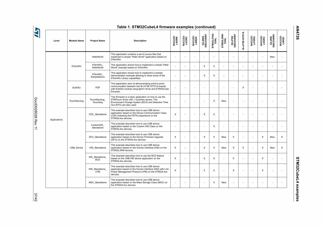
AN
472
6S
TM
32C
ub
eL
4 ex
amp
les
DocID
028028 R
ev 1137
/42
Applications
STemWin
HelloWorldThis application contains a set of source files that implement a simple "Hello World" application based on STemWin.
- - - - - - - - - - New -
STemWin_HelloWorld
This application shows how to implement a simple "Hello World" example based on STemWin.
- - - X X - - - - - - -
STemWin_SampleDemo
This application shows how to implement a sample demonstration example allowing to show some of the STemWin Library capabilities.
- - - X X - - - - - - -
SubGhz P2P
This application aims at demonstrating point-to-point communication between two B-L475E-IOT01A boards with SubGhz module using Spirit1 driver and STM32Cube firmware.
- - - - - - - X - - - -
TouchSensingTouchSensing_
1touchkey
This firmware is a basic application on how to use the STMTouch driver with 1 touchkey sensor. The Environment Change System (ECS) and Detection Time Out (DTO) are also used.
- - - - X New - - - - - -
USB_Device
CDC_Standalone
This example describes how to use USB device application based on the Device Communication Class (CDC) following the PSTN subprotocol on the STM32L4xx devices.
X - - X X - - - - - - -
CustomHID_Standalone
This example describes how to use USB device application based on the Custom HID Class on the STM32L4xx devices.
- - - - X - - - - - - -
DFU_StandaloneThis example describes how to use USB device application based on the Device Firmware Upgrade (DFU) on the STM32L4xx devices.
X - - X X New X - - X New X
HID_StandaloneThis example describes how to use USB device application based on the Human Interface (HID) on the STM32L4R9I devices.
X - - X X New X X - X New X
HID_Standalone_BCD
This example describes how to use the BCD feature based on the USB HID device application on the STM32L4xx devices.
X - - X X - X - - X - -
HID_Standalone_LPM
This example describes how to use USB device application based on the Human Interface (HID) with Link Power Management Protocol (LPM) on the STM32L4xx devices.
X - - X X - X - - X - -
MSC_StandaloneThis example describes how to use USB device application based on the Mass Storage Class (MSC) on the STM32L4xx devices.
- - - - X New - - - - - -
Table 1. STM32CubeL4 firmware examples (continued)
Level Module Name Project Name Description
NU
CL
EO
-L
452R
E
NU
CL
EO
-L
433
RC
NU
CL
EO
-L
496Z
G
32L
496
GD
ISC
OV
ER
Y
ST
M3
2L
476G
-E
VA
L
ST
M3
2L4
R9
I-E
VA
L
32L
476
GD
ISC
OV
ER
Y
B-L
475
E-I
OT
01A
NU
CL
EO
-L
476
RG
NU
CL
EO
-L
432
KC
32L
4R
9I
DIS
CO
VE
RY
NU
CL
EO
-L
4R5Z
I

ST
M3
2Cu
be
L4
ex
amp
les
AN
472
6
38/4
2D
ocID028
028 Rev 11
Applications
USB_Host
CDC_Standalone
This application is a part of the USB Host Library package using STM32Cube firmware. It describes how to use USB host application based on the Communication Class (CDC) on the STM32L4xx devices.
- - - - X - - - - - - -
HID_StandaloneThis application describes how to use USB host application based on the Humain Interface Class (HID) on the STM32L4xx devices.
- - - X X - - - - - - X
MSCThis example describes how to use USB host application based on the Mass Storage Class (MSC) on the STM32L4xx devices.
- - - - - - - X - - - -
MSC_StandaloneThis example describes how to use USB host application based on the Mass Storage Class (MSC) on the STM32L4xx devices.
- - - X X New - - - - New X
WiFi
WiFi_Client_Server
This application shows how to use the Es-WiFi module to perform a TCP client mode using STM32Cube HAL. It demonstrates how to set up a client program and connect it to a TCP server.
- - - - - - - X - - - -
WiFi_HTTP_ServerThis application shows how to make HTTP requests using the Es-WiFi module based on STM32Cube HAL.
- - - - - - - X - - - -
Total number of applications: 108 15 0 10 11 28 11 5 11 1 5 6 5
Table 1. STM32CubeL4 firmware examples (continued)
Level Module Name Project Name Description
NU
CL
EO
-L
452R
E
NU
CL
EO
-L
433
RC
NU
CL
EO
-L
496Z
G
32L
496
GD
ISC
OV
ER
Y
ST
M3
2L
476G
-E
VA
L
ST
M3
2L4
R9
I-E
VA
L
32L
476
GD
ISC
OV
ER
Y
B-L
475
E-I
OT
01A
NU
CL
EO
-L
476
RG
NU
CL
EO
-L
432
KC
32L
4R
9I
DIS
CO
VE
RY
NU
CL
EO
-L
4R5Z
I
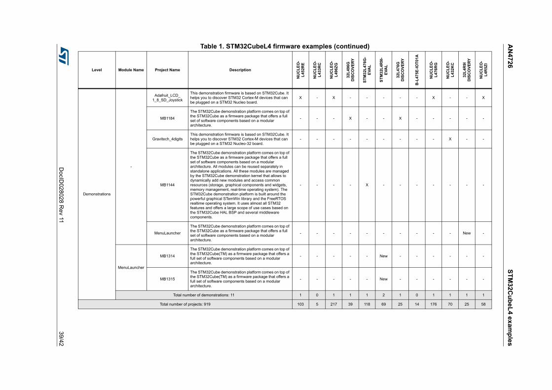
AN
472
6S
TM
32C
ub
eL
4 ex
amp
les
DocID
028028 R
ev 1139
/42
Demonstrations
-
Adafruit_LCD_1_8_SD_Joystick
This demonstration firmware is based on STM32Cube. It helps you to discover STM32 Cortex-M devices that can be plugged on a STM32 Nucleo board.
X - X - - - - - X - - X
MB1184
The STM32Cube demonstration platform comes on top of the STM32Cube as a firmware package that offers a full set of software components based on a modular architecture.
- - - X - - X - - - - -
Gravitech_4digitsThis demonstration firmware is based on STM32Cube. It helps you to discover STM32 Cortex-M devices that can be plugged on a STM32 Nucleo-32 board.
- - - - - - - - - X - -
MB1144
The STM32Cube demonstration platform comes on top of the STM32Cube as a firmware package that offers a full set of software components based on a modular architecture. All modules can be reused separately in standalone applications. All these modules are managed by the STM32Cube demonstration kernel that allows to dynamically add new modules and access common resources (storage, graphical components and widgets, memory management, real-time operating system). The STM32Cube demonstration platform is built around the powerful graphical STemWin library and the FreeRTOS realtime operating system. It uses almost all STM32 features and offers a large scope of use cases based on the STM32Cube HAL BSP and several middleware components.
- - - - X - - - - - - -
MenuLauncher
The STM32Cube demonstration platform comes on top of the STM32Cube as a firmware package that offers a full set of software components based on a modular architecture.
- - - - - - - - - - New -
MenuLauncher
MB1314
The STM32Cube demonstration platform comes on top of the STM32Cube(TM) as a firmware package that offers a full set of software components based on a modular architecture.
- - - - - New - - - - - -
MB1315
The STM32Cube demonstration platform comes on top of the STM32Cube(TM) as a firmware package that offers a full set of software components based on a modular architecture.
- - - - - New - - - - - -
Total number of demonstrations: 11 1 0 1 1 1 2 1 0 1 1 1 1
Total number of projects: 919 103 5 217 39 118 69 25 14 176 70 25 58
Table 1. STM32CubeL4 firmware examples (continued)
Level Module Name Project Name Description
NU
CL
EO
-L
452R
E
NU
CL
EO
-L
433
RC
NU
CL
EO
-L
496Z
G
32L
496
GD
ISC
OV
ER
Y
ST
M3
2L
476G
-E
VA
L
ST
M3
2L4
R9
I-E
VA
L
32L
476
GD
ISC
OV
ER
Y
B-L
475
E-I
OT
01A
NU
CL
EO
-L
476
RG
NU
CL
EO
-L
432
KC
32L
4R
9I
DIS
CO
VE
RY
NU
CL
EO
-L
4R5Z
I
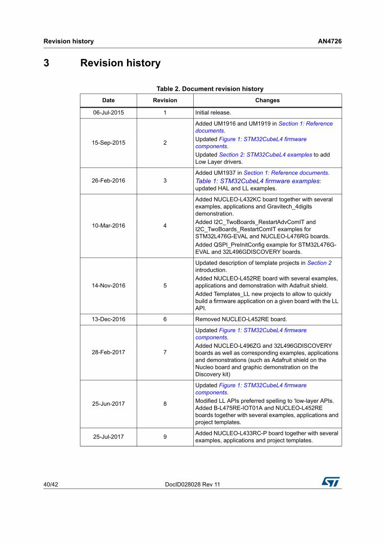
Revision history AN4726
40/42 DocID028028 Rev 11
3 Revision history
Table 2. Document revision history
Date Revision Changes
06-Jul-2015 1 Initial release.
15-Sep-2015 2
Added UM1916 and UM1919 in Section 1: Reference documents.
Updated Figure 1: STM32CubeL4 firmware components.
Updated Section 2: STM32CubeL4 examples to add Low Layer drivers.
26-Feb-2016 3Added UM1937 in Section 1: Reference documents.
Table 1: STM32CubeL4 firmware examples: updated HAL and LL examples.
10-Mar-2016 4
Added NUCLEO-L432KC board together with several examples, applications and Gravitech_4digits demonstration.
Added I2C_TwoBoards_RestartAdvComIT and I2C_TwoBoards_RestartComIT examples for STM32L476G-EVAL and NUCLEO-L476RG boards.
Added QSPI_PreInitConfig example for STM32L476G-EVAL and 32L496GDISCOVERY boards.
14-Nov-2016 5
Updated description of template projects in Section 2 introduction.
Added NUCLEO-L452RE board with several examples, applications and demonstration with Adafruit shield.
Added Templates_LL new projects to allow to quickly build a firmware application on a given board with the LL API.
13-Dec-2016 6 Removed NUCLEO-L452RE board.
28-Feb-2017 7
Updated Figure 1: STM32CubeL4 firmware components.
Added NUCLEO-L496ZG and 32L496GDISCOVERY boards as well as corresponding examples, applications and demonstrations (such as Adafruit shield on the Nucleo board and graphic demonstration on the Discovery kit)
25-Jun-2017 8
Updated Figure 1: STM32CubeL4 firmware components.
Modified LL APIs preferred spelling to ‘low-layer APIs. Added B-L475RE-IOT01A and NUCLEO-L452RE boards together with several examples, applications and project templates.
25-Jul-2017 9Added NUCLEO-L433RC-P board together with several examples, applications and project templates.

DocID028028 Rev 11 41/42
AN4726 Revision history
41
01-Sep-2017 10Added NUCLEO-L4R5ZI board together with several examples, applications and demonstration based on Adafruit shield.
3-Nov-2017 11Added STM32L4R9I-EVAL and 32L4R9IDISCOVERY boards together with several examples, applications, demonstrations and project templates.
Table 2. Document revision history (continued)
Date Revision Changes
AN4726
42/42 DocID028028 Rev 11
IMPORTANT NOTICE – PLEASE READ CAREFULLY
STMicroelectronics NV and its subsidiaries (“ST”) reserve the right to make changes, corrections, enhancements, modifications, and improvements to ST products and/or to this document at any time without notice. Purchasers should obtain the latest relevant information on ST products before placing orders. ST products are sold pursuant to ST’s terms and conditions of sale in place at the time of order acknowledgement.
Purchasers are solely responsible for the choice, selection, and use of ST products and ST assumes no liability for application assistance or the design of Purchasers’ products.
No license, express or implied, to any intellectual property right is granted by ST herein.
Resale of ST products with provisions different from the information set forth herein shall void any warranty granted by ST for such product.
ST and the ST logo are trademarks of ST. All other product or service names are the property of their respective owners.
Information in this document supersedes and replaces information previously supplied in any prior versions of this document.
© 2017 STMicroelectronics – All rights reserved