status of virgo experiment matteo barsuglia, lal/cnrs orsay
DESCRIPTION
Status of Virgo experiment Matteo Barsuglia, LAL/CNRS Orsay On behalf of the Virgo Collaboration TAMA symposium, Feb 18 th 2005. The VIRGO Collaboration. V IRGO is an Italian-French collaboration. ITALY - INFN Firenze-Urbino Frascati Napoli Perugia Pisa Roma. FRANCE - CNRS - PowerPoint PPT PresentationTRANSCRIPT
Status of Virgo experiment
Matteo Barsuglia, LAL/CNRS Orsay
On behalf of the Virgo Collaboration
TAMA symposium, Feb 18th 2005
The VIRGO Collaboration
VIRGO is an Italian-French collaboration
ITALY - INFN
Firenze-UrbinoFrascatiNapoli PerugiaPisaRoma
FRANCE - CNRS
ESPCI – ParisIPN – LyonLAL – OrsayLAPP – AnnecyOCA - Nice

Virgo site (20km from Pisa, Italy)at
European Gravitational Obseervatory (EGO)

Expected Sensitivity
Seismic wall at ~ 4 Hz

The VIRGO Interferometer
Laser 20 W
Output Mode Cleaner4 cm long
Michelson Interferometer with3 km long Fabry-Perot cavitiesin the arms and Power Recycling
Input Mode Cleaner144 m long
High quality optics are:
located in vacuum suspended from
multi-stage pendulums
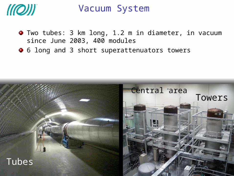
Vacuum System
Two tubes: 3 km long, 1.2 m in diameter, in vacuum since June 2003, 400 modules6 long and 3 short superattenuators towers
Tubes
TowersCentral area

The Suspension System
The Superattenuator (SA) is designed to isolate the optical components from seismic activities (local disturbances).
Working principle multistage pendulum
Expected attenuation @10 Hz: 1014
Residual mirror motion (rms)
rotation <1 rad longitudinal <1 m
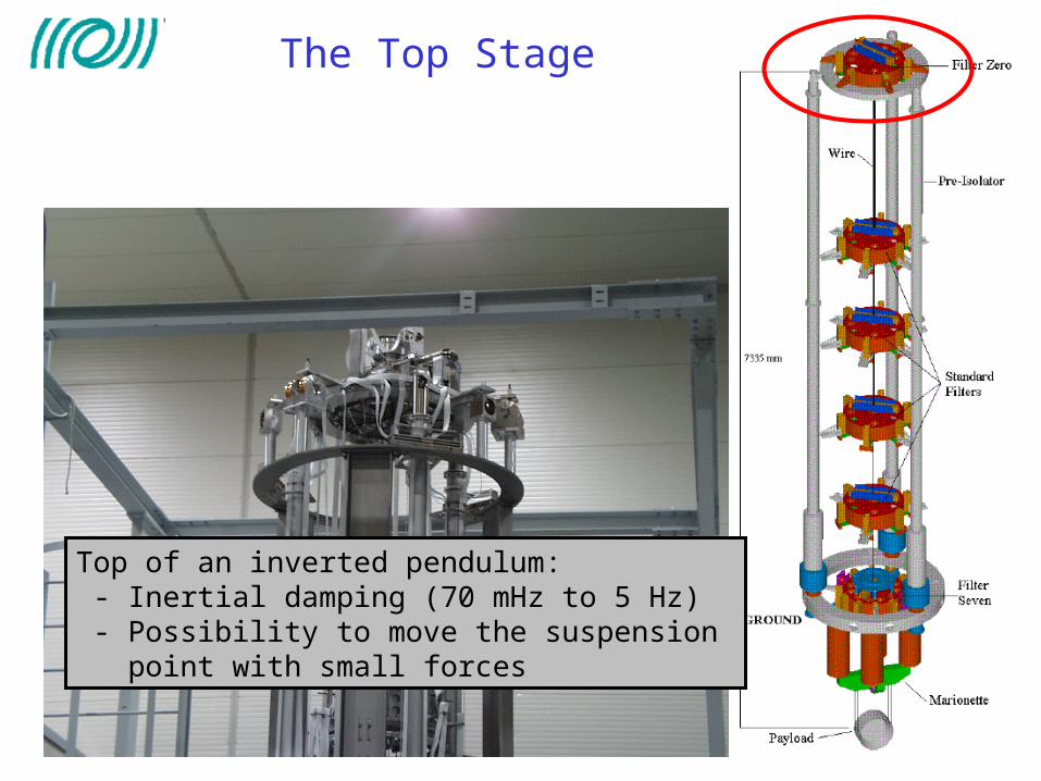
The Top Stage
Top of an inverted pendulum: - Inertial damping (70 mHz to 5 Hz) - Possibility to move the suspension point with small forces

Passive Filters
Five seismic filters:
Suspended by steel wires Vertical isolation by a combination
of cantilever springs and magnetic anti-springs

The Local Controls
Marionette control:CCD camera, optical levers and fourcoil-magnet actuators: <2 Hz

Fast actuators
Reference mass and mirror,four coil-magnet actuators

Injection System
IMC
RFC

Laser
Located on an optical table outside the vacuum
Nd:YAG master commercial CW single mode (700 mW) @1064 nm
Phase locked to a Nd:YVO4 slave (monolithic ring cavity)
Pumped by two laser diodes at 806 nm (40 W power)
Output power: 20 W
Slave
Master

Input Mode Cleaner
Triangular cavity, 144 m long, Finesse=1000Input optics and two flat mirrors are located on a suspended optical benchEnd mirror suspended with a reference massfor actuationTransmission 50%
Injection Bench
Mode Cleaner Mirror

Detection System
Suspended bench in vacuum with optics for beam adjustments and the output mode cleaner (OMC)Detection, amplification and demodulation on external bench
Suspended bench External bench
Output Mode-Cleaner

Output Mode Cleaner
Output Mode-Cleaner
Detection Bench
4 cm long ring cavityContrast improvement ~ 10Length control via temperature (Peltier element)Lock acquisition takes 10 min
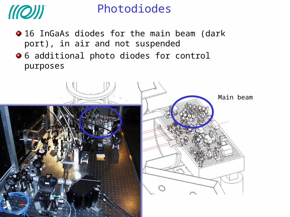
Photodiodes
16 InGaAs diodes for the main beam (dark port), in air and not suspended6 additional photo diodes for control purposes
External bench
Output Mode-Cleaner
Main beam

Digital Controls
Fully digital control, local and global
Feedback is send with 20-bit DACs @ 10kHz to thesuspensions
The suspension control is performed by dedicated DSPs (one per suspension)
Interferometer signals are acquired with 16-bit ADCs @ 20 kHz. The data is transferred via optical linksto Global Control (dedicated hardware and software that computes correction signals and sends them to the mirror DSPs)

Sensing and Control
Modulation-demodulationscheme with only one modulation frequency (6 MHz) to control:
4 lengths 10 angles
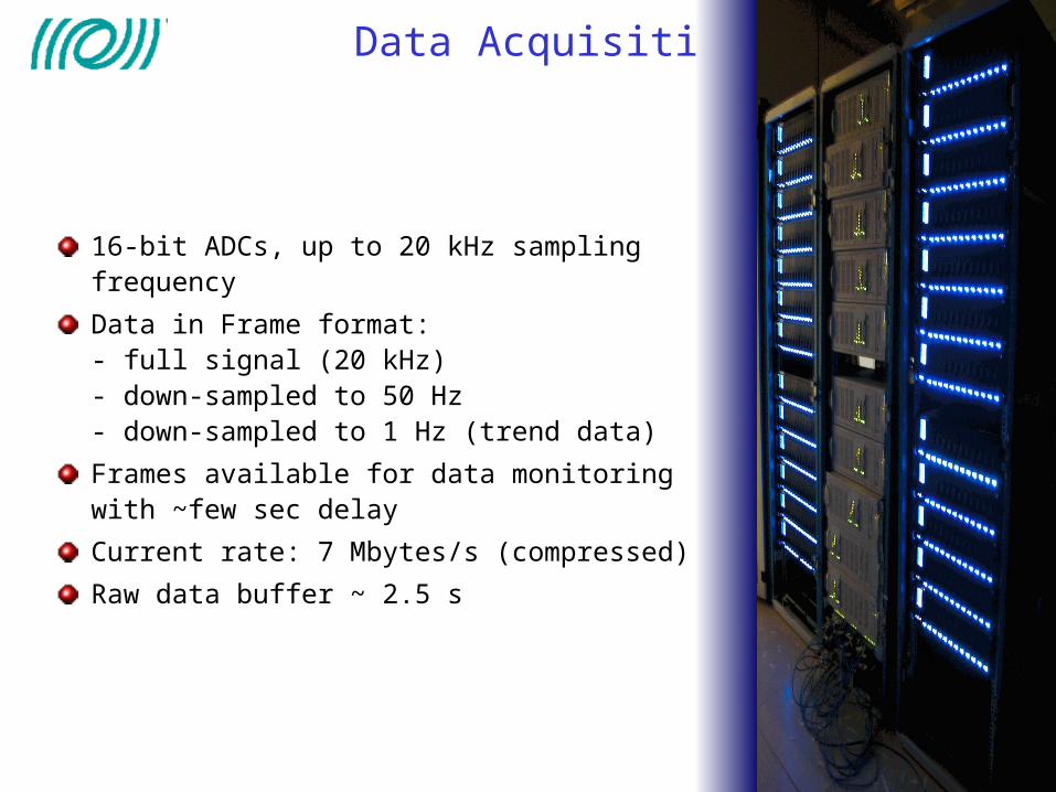
Data Acquisition and Storage
16-bit ADCs, up to 20 kHz sampling frequency
Data in Frame format:- full signal (20 kHz)- down-sampled to 50 Hz- down-sampled to 1 Hz (trend data)
Frames available for data monitoringwith ~few sec delay
Current rate: 7 Mbytes/s (compressed)
Raw data buffer ~ 2.5 s
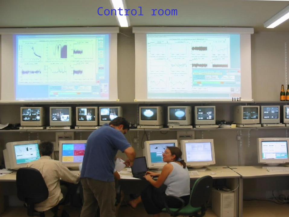
Control room

Current Status
2001-2002 Commissioning of the central interferometer and the injection system
2002-2003 Tubes commissioning and final mirror installation Since September 2003 commissioning of the full interferometer
Central Interferometer (CITF)

Commissioning of VIRGO
The commissioning of the full detector has been divided into
three phases:
Phase A (sept 2003 - feb2004): the 3 km long arm cavities
separatly
Phase B (feb 2004 – summer 2004): recombined Michelson
interferometer
Phase C (from summer 2004) : Michelson interferometer with
Power Recycling (full detector)

Commissioning of the arms
• Test the cavity locking, and digital control chain • Test the automatic alignment (with the Anderson
technique)• Test the frequency stabilization • Test the locking of the output mode-cleaner

North Arm Cavity commissioning
PR misaligned
West arm misaligned
Phase A: the two arm cavities are used separatly, starting with the north arm;
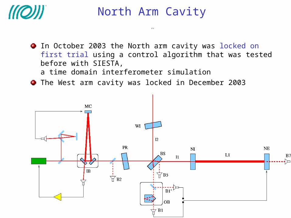
North Arm Cavity
In October 2003 the North arm cavity was locked on first trial using a control algorithm that was tested before with SIESTA, a time domain interferometer simulationThe West arm cavity was locked in December 2003

Recombined Interferometer
Phase B:Recombined Interferometer
- B2 (P) used to control common mode (L1+L2)- B2 (Q) used to control beam splitter- B1/B1’ used to control differential mode (L1-L2)
PR misaligned
Recombined locked in February 2004

Automatic Alignment
Anderson technique:
- Modulation frequency coincident with cavity TEM01 mode
- Two split photo diodes in transmission of the cavity (at two different Guoy phases)
- Four signals to control the 2x2 mirror angular positions (NI, NE)

Automatic Alignment
• Alignment control allows to switch off local controls
• Power inside the cavities becomes more stable
• Installed and tested for the recombined interferometer
• Bandwidth ~3 Hz• Residual fluctuations ~0.5
urad rms (1 nrad @ 10 Hz)
Frequency stabilization
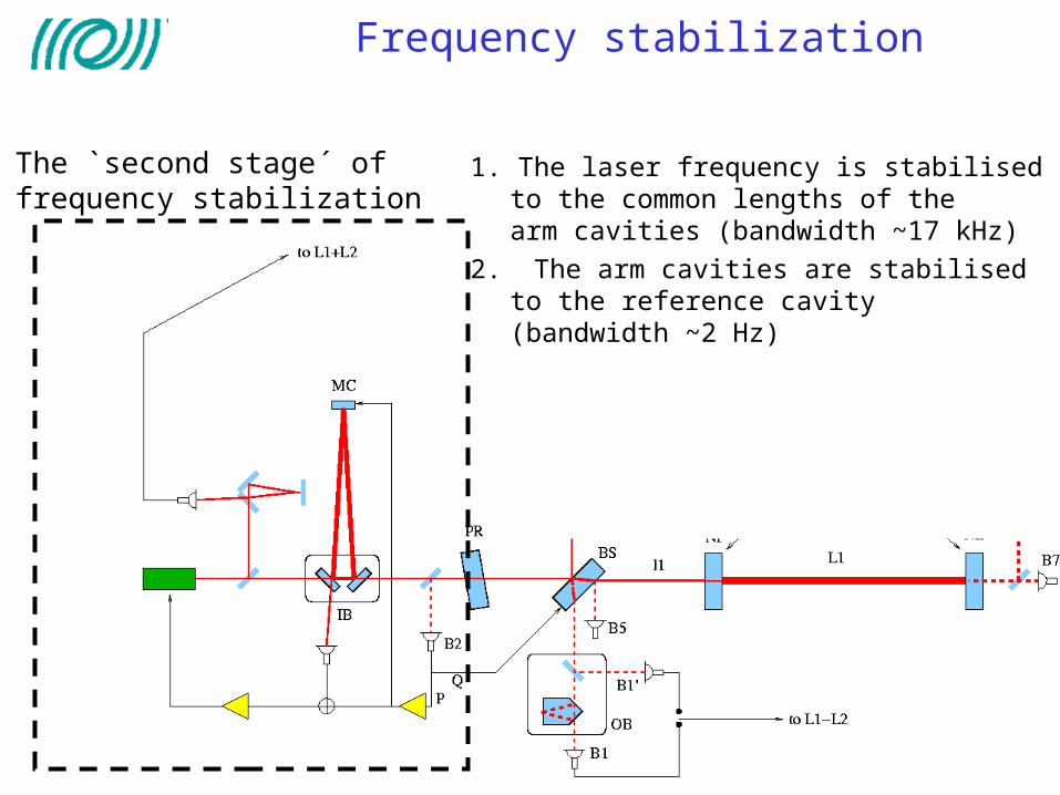
The `second stage´ of frequency stabilization
1. The laser frequency is stabilised to the common lengths of thearm cavities (bandwidth ~17 kHz)
2. The arm cavities are stabilised to the reference cavity (bandwidth ~2 Hz)
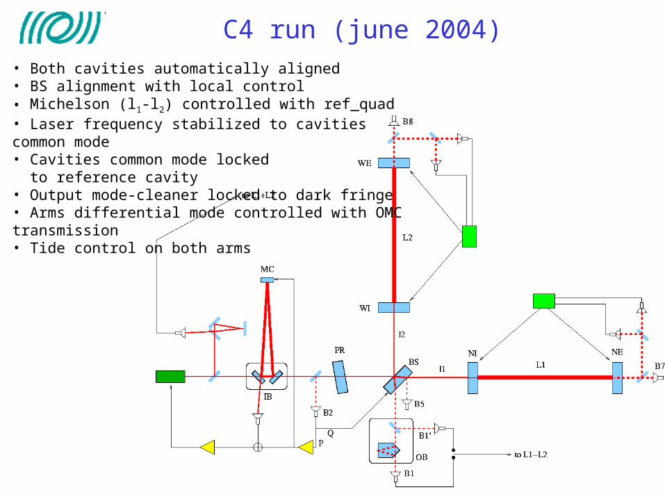
C4 run (june 2004)• Both cavities automatically aligned• BS alignment with local control• Michelson (l1-l2) controlled with ref_quad• Laser frequency stabilized to cavities common mode• Cavities common mode locked to reference cavity• Output mode-cleaner locked to dark fringe• Arms differential mode controlled with OMC transmission• Tide control on both arms

C4-june 2004 (recombined)
• Configuration: recombined ITF with 90% complete control system:- automatic alignment of input beam and beam splitter missing
• Duration: 5 days • Test periods at the beginning and at the end of the run (~ 0.5 day)• 9 losses of lock during quiet periods (all understood, one due to an earthquake in Alaska !)• Longest locked period: ~ 28 h, relatively stable noise level
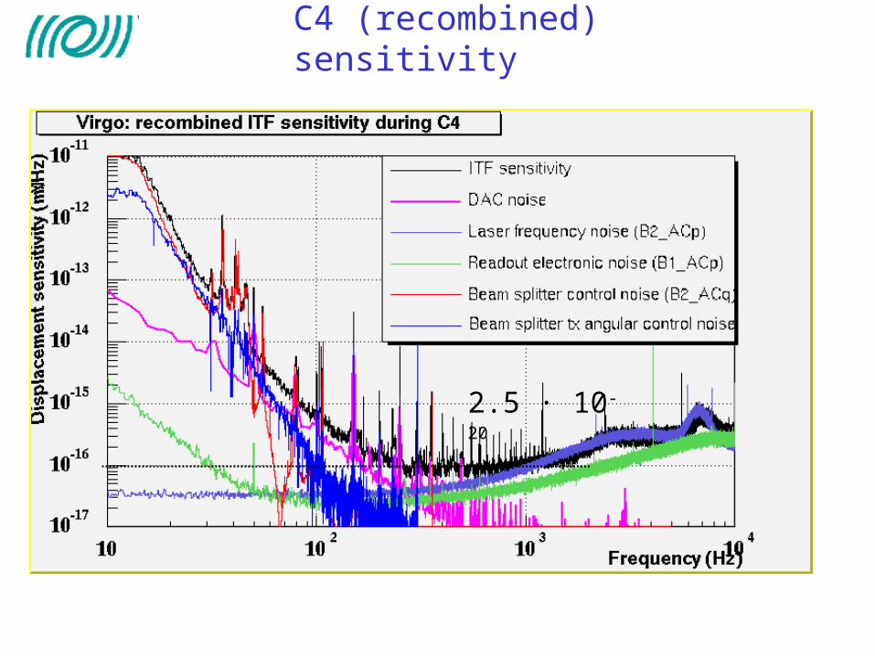
C4 (recombined) sensitivity
2.5 · 10-20

DAC noise
10-1
100
101
102
103
10-20
10-15
10-10
10-5
Actuators noise: current status
Frequency (Hz)
m/H
z1/2
Reference Mass - Mirror Actuators NoiseFilter #7 - Marionetta Actuators NoiseVIRGO Sentivity
103

Transfer of the low frequency component of the locking feedback force to the marionette
DC-0.01 Hz
0.01-1.5 Hz
1.5-50 Hz
Suspension hierarchical control - I
• Main difficulty:Driving of tilt modes when pushing on the marionette need for a good diagonalization of the driving

• Transfer of locking force to marionette tested
• Crossing frequency ~ 0.5 Hz 1.5 Hz 8 Hz !
Force applied to the mirror (via reference mass coils) decreased by ~10
Force applied to the mirror (a.u.) Force applied to marionette (a.u.)
Suspension hierarchical control - II

• Almost all the controls running • Noise quite understood• C4/C5 data used for data analysis purposes
in july 2004 lock acquisition trial for the recycled ITF started
After C4, recombined ITF
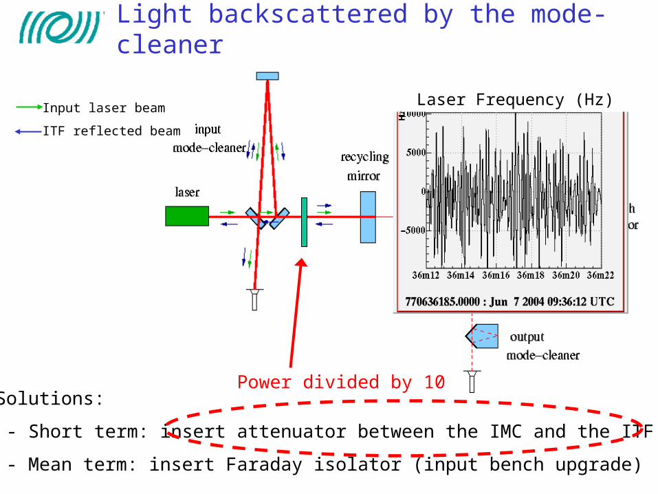
Input laser beam
ITF reflected beam
• Solutions:
- Short term: insert attenuator between the IMC and the ITF
- Mean term: insert Faraday isolator (input bench upgrade)
Laser Frequency (Hz)
Light backscattered by the mode-cleaner
Power divided by 10

“A recycled ITF with a low recycling factor is similar to recombined interferometer “
Lock the 4 degrees of freedom of the ITF on the half or white fringe
Bring the interferometer slowly on the dark fringe
Lock acquisition of the recycled ITF
The variable finesse lock acquisition
North arm
West arm
- Lock of the long arms indipendently with the
end photodiodes
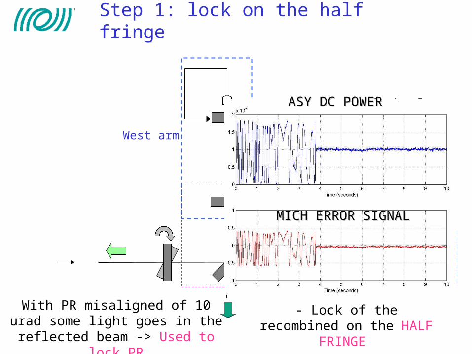
- Lock of the recombined on the HALF FRINGE
With PR misaligned of 10 urad some light goes in the reflected
beam -> Used to lock PR
ASY DC POWERASY DC POWER
MICH ERROR SIGNALMICH ERROR SIGNAL
Step 1: lock on the half fringe

Ref_3f phase
Asy_ DC
West transmission_phase
0 0.2 0.4 0.6 0.8 1 1.2 1.4 1.6 1.8 20
0.2
0.4
0.6
0.8
1
0 0.2 0.4 0.6 0.8 1 1.2 1.4 1.6 1.8 2-0.5
0
0.5
1
North transmission_phase
Step 2: align the power recycling mirror
Coming from TAMA experience

Pick_off_Phase
Ref_3f phase
LASER
West transmission_phase diff arm mode
0 0.2 0.4 0.6 0.8 1 1.2 1.4 1.6 1.8 20
0.2
0.4
0.6
0.8
1
0 0.2 0.4 0.6 0.8 1 1.2 1.4 1.6 1.8 2-0.5
0
0.5
1
Asy_ DC
Step 3: common mode laser frequency

MICH ERROR SIGNALMICH ERROR SIGNAL
ASY DC POWERASY DC POWER
Offset : 0.5 0.2
Step 4: reducing the offset

Ref_3f phase
LASER
West transmission_phase
0 0.2 0.4 0.6 0.8 1 1.2 1.4 1.6 1.8 20
0.2
0.4
0.6
0.8
1
0 0.2 0.4 0.6 0.8 1 1.2 1.4 1.6 1.8 2-0.5
0
0.5
1
Step 5: change the error signal for the michelson control DCAC
Pick_off_PhasePick_off_Quad

0 0.2 0.4 0.6 0.8 1 1.2 1.4 1.6 1.8 20
0.2
0.4
0.6
0.8
1
0 0.2 0.4 0.6 0.8 1 1.2 1.4 1.6 1.8 2-0.5
0
0.5
1
Recycling gain big increase: intermediate steps to arrive to the Recycling gain big increase: intermediate steps to arrive to the dark fringedark fringe
ITF on the operating point
Step 6: going to the dark fringe

Power on beam splitter during lock acquisition
Recombined interferometer
Recycling gain ~ 25-30
300 times

Ref_3f phase prcl
LASER
Asy_Quad diff arm mode
Switch to a “detection” mode
Pick_off_Phase common arm mode
Pick_off_Quad mich

2.5 hours lock Stored power

C5 run – december 2005
• Recycled ITF
• Second stage of frequency stabilization (common mode servo)
• output mode-cleaner
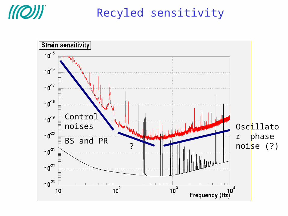
Control noises
BS and PR
Oscillator phase noise (?)?
Recyled sensitivity

Recyled interferomter high frequency sensitivity
During the lock of the recycled ITF the high frequency noise is more than ~ 40 times higher than the expected electronic noiseThe level of this noise fluctuates with the quality of the alignemnt
C5 recycled sensitivity
Electronic noise (with closed shutter)
Shot noise
Phase noise ( model with = 0.45 rad/(Hz) )

• Run the automatic alignment
• Complete the alignmnet/locking automation
• Prepare known noises reduction:
• control noises (< 100 Hz)
• phase noise (>500 Hz)
Plans from now to april

• Install new injection bench with Faraday isolator (2-4 weeks stop)
• Run the interferometer with 10 times more power
Plans after april
• Noise hunting

New injection bench Faraday isolator
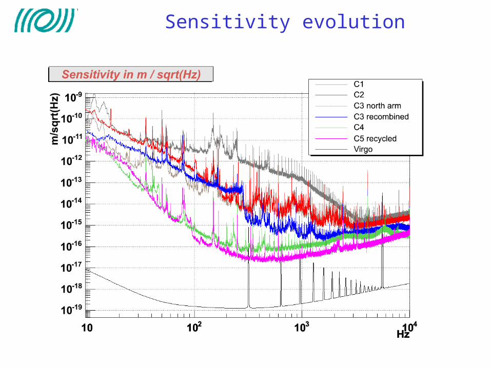
Sensitivity evolution
Summary
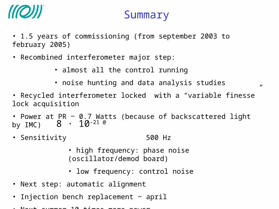
• 1.5 years of commissioning (from september 2003 to february 2005)
• Recombined interferometer major step:
• almost all the control running
• noise hunting and data analysis studies
• Recycled interferometer locked with a “variable finesse” lock acquisition
• Power at PR ~ 0.7 Watts (because of backscattered light by IMC)
• Sensitivity 500 Hz
• high frequency: phase noise (oscillator/demod board)
• low frequency: control noise
• Next step: automatic alignment
• Injection bench replacement ~ april
• Next summer 10 times more power
8 · 10-21 @