stats group - pigging products and services … · © stats group stats group process &...
TRANSCRIPT
© STATS GROUP
STATS GROUPProcess & Pipeline Integrity Solutions
Emergency Pipeline Repair Isolation SystemsDeveloped to Facilitate Pipeline Repair of Unpiggable Defects
PPSA14 November 2012Dale Millward
© STATS GROUP
What will be Presented
Definition of Double Block & Bleed isolation and testing requirements
Overview of Tecno Plug™ and BISEP™ isolation tools
Developments in isolation technology for Emergency Pipeline Repair of unpiggable defects
Animations
• BISEP™ isolations for unpiggable defect repair
• Newly developed Tecno Plug™ isolations for unpiggable defect repair
Slide No. 2
© STATS GROUP
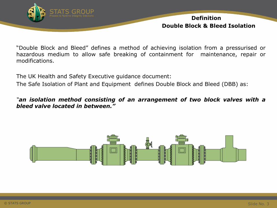
Definition
Double Block & Bleed Isolation
“Double Block and Bleed” defines a method of achieving isolation from a pressurised orhazardous medium to allow safe breaking of containment for maintenance, repair ormodifications.
The UK Health and Safety Executive guidance document:
The Safe Isolation of Plant and Equipment defines Double Block and Bleed (DBB) as:
“an isolation method consisting of an arrangement of two block valves with ableed valve located in between.”
Slide No. 3
© STATS GROUP
Proved
Double Block & Bleed Isolation
A proved DBB isolation exists where the sealing integrity of two separate isolation barriers are proven before the isolation is relied upon.
• Each part of the isolation should be proved separately
• BOTH isolation seals must be proven using full isolated pressure in the correct direction
Slide No. 4
© STATS GROUP
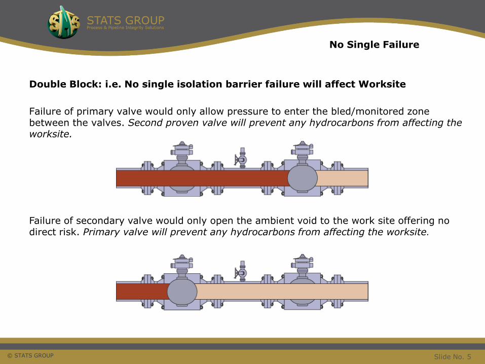
Double Block: i.e. No single isolation barrier failure will affect Worksite
Failure of primary valve would only allow pressure to enter the bled/monitored zone between the valves. Second proven valve will prevent any hydrocarbons from affecting the worksite.
Failure of secondary valve would only open the ambient void to the work site offering no direct risk. Primary valve will prevent any hydrocarbons from affecting the worksite.
No Single Failure
Slide No. 5

© STATS GROUP
Monitoring and Control
After testing both seals the void between the seals should be:
• Vented to provide a ZERO ENERGY ZONE
• Monitored periodically for any pressure rise
• Be able to vent any potential pressure build up
This will ensure any pressure build up from a passing primary valve is detected and vented to a safe area, whist being retained by the secondary valve. Preventing any hydrocarbons or pressure from affecting the worksite.
BP – Guidance on Practice for Safe Isolation and Reinstatement of Plant specifies:
“Double Block and Bleed consists of the closure of two block valves in series with anintermediate bleed valve. The integrity of both valves shall be tested separately and thebleed valve will then be left in the closed position between periodic integrity checks.”
Slide No. 6
© STATS GROUP
The reality is that that most of the time two leak tight valves are not available and Double Block and Bleed Isolation can not be achieved or be proven.
DBB Simple in principlemore complicated in practice
© STATS GROUP
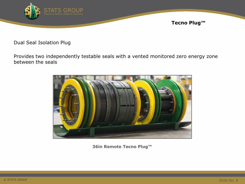
Dual Seal Isolation Plug
Provides two independently testable seals with a vented monitored zero energy zone between the seals
36in Remote Tecno Plug™
Tecno Plug™
Slide No. 8
© STATS GROUP
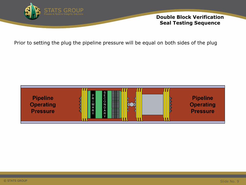
Prior to setting the plug the pipeline pressure will be equal on both sides of the plug
Double Block Verification Seal Testing Sequence
Slide No. 9
© STATS GROUP
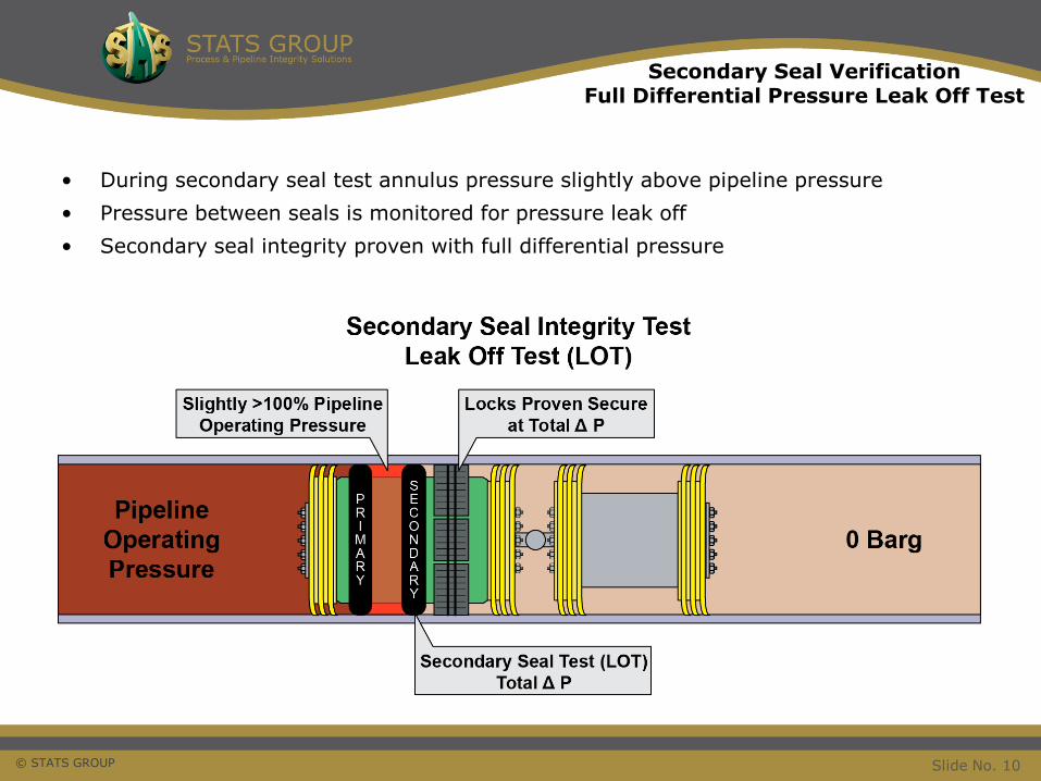
• During secondary seal test annulus pressure slightly above pipeline pressure
• Pressure between seals is monitored for pressure leak off
• Secondary seal integrity proven with full differential pressure
Secondary Seal VerificationFull Differential Pressure Leak Off Test
Slide No. 10
© STATS GROUP
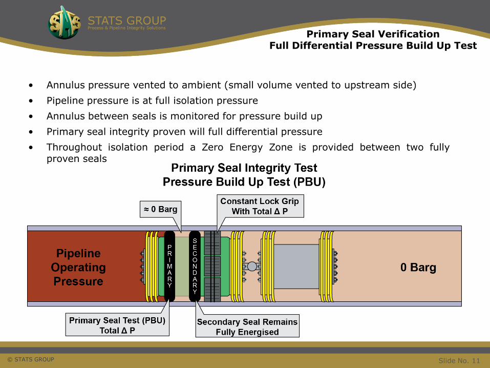
• Annulus pressure vented to ambient (small volume vented to upstream side)
• Pipeline pressure is at full isolation pressure
• Annulus between seals is monitored for pressure build up
• Primary seal integrity proven will full differential pressure
• Throughout isolation period a Zero Energy Zone is provided between two fullyproven seals
Primary Seal VerificationFull Differential Pressure Build Up Test
Slide No. 11
© STATS GROUP
Self-Energisation
Isolation Fail-safe Feature
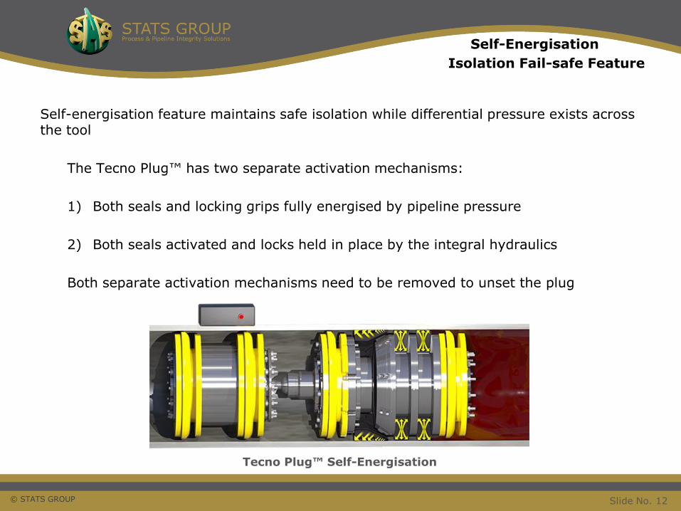
Self-energisation feature maintains safe isolation while differential pressure exists across the tool
The Tecno Plug™ has two separate activation mechanisms:
1) Both seals and locking grips fully energised by pipeline pressure
2) Both seals activated and locks held in place by the integral hydraulics
Both separate activation mechanisms need to be removed to unset the plug
Tecno Plug™ Self-Energisation
Slide No. 12
© STATS GROUP
Passive Unset
Fail-safe Unset and Recovery Feature
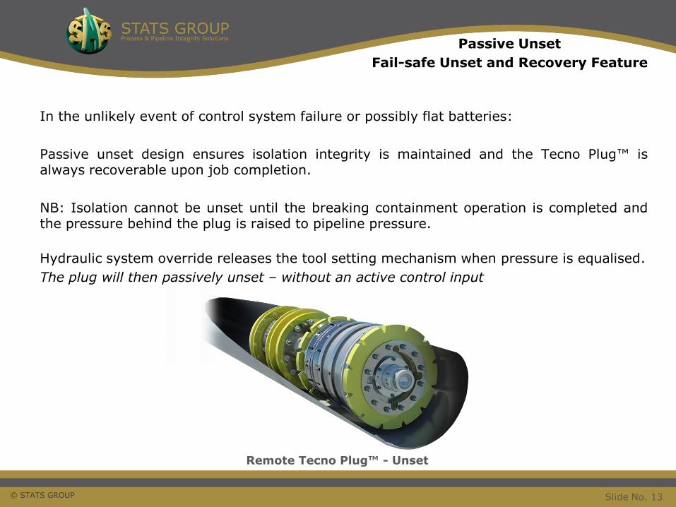
In the unlikely event of control system failure or possibly flat batteries:
Passive unset design ensures isolation integrity is maintained and the Tecno Plug™ isalways recoverable upon job completion.
NB: Isolation cannot be unset until the breaking containment operation is completed andthe pressure behind the plug is raised to pipeline pressure.
Hydraulic system override releases the tool setting mechanism when pressure is equalised.
The plug will then passively unset – without an active control input
Remote Tecno Plug™ - Unset
Slide No. 13
© STATS GROUP
Tecno Plug™
Isolation Projects
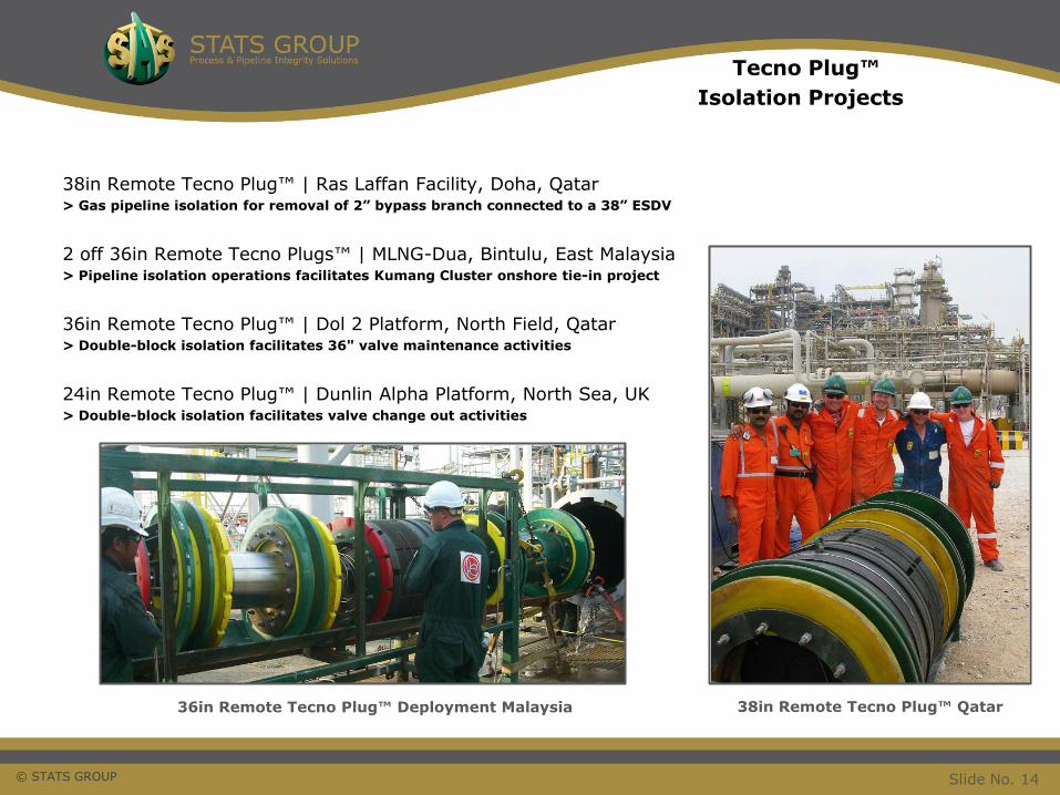
38in Remote Tecno Plug™ | Ras Laffan Facility, Doha, Qatar > Gas pipeline isolation for removal of 2” bypass branch connected to a 38” ESDV
2 off 36in Remote Tecno Plugs™ | MLNG-Dua, Bintulu, East Malaysia> Pipeline isolation operations facilitates Kumang Cluster onshore tie-in project
36in Remote Tecno Plug™ | Dol 2 Platform, North Field, Qatar > Double-block isolation facilitates 36" valve maintenance activities
24in Remote Tecno Plug™ | Dunlin Alpha Platform, North Sea, UK > Double-block isolation facilitates valve change out activities
36in Remote Tecno Plug™ Deployment Malaysia 38in Remote Tecno Plug™ Qatar
Slide No. 14
© STATS GROUP
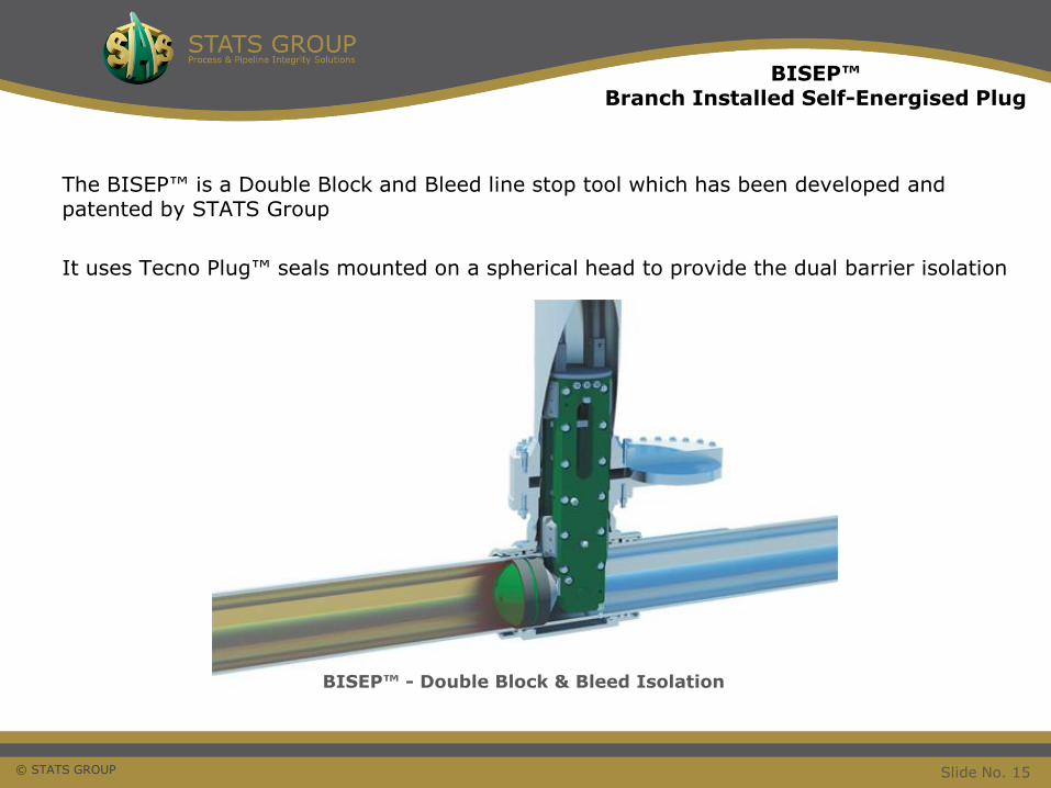
The BISEP™ is a Double Block and Bleed line stop tool which has been developed and patented by STATS Group
It uses Tecno Plug™ seals mounted on a spherical head to provide the dual barrier isolation
BISEP™ - Double Block & Bleed Isolation
BISEP™Branch Installed Self-Energised Plug
Slide No. 15
© STATS GROUP
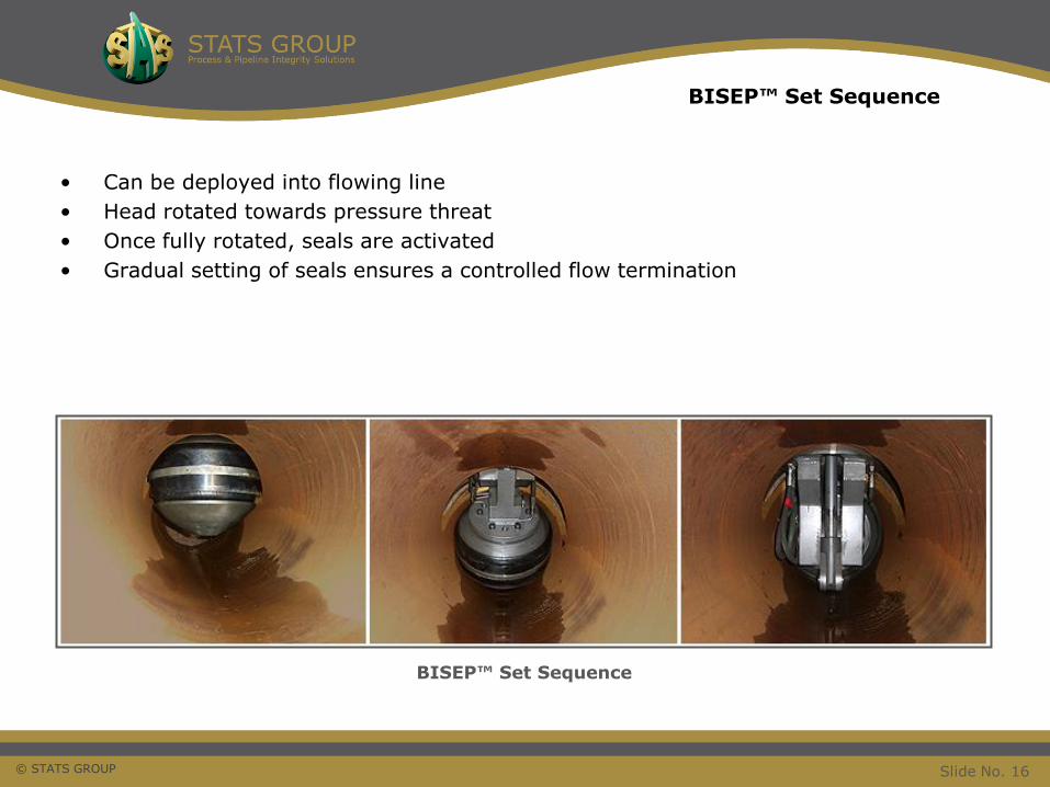
• Can be deployed into flowing line
• Head rotated towards pressure threat
• Once fully rotated, seals are activated
• Gradual setting of seals ensures a controlled flow termination
BISEP™ Set Sequence
BISEP™ Set Sequence
Slide No. 16
© STATS GROUP
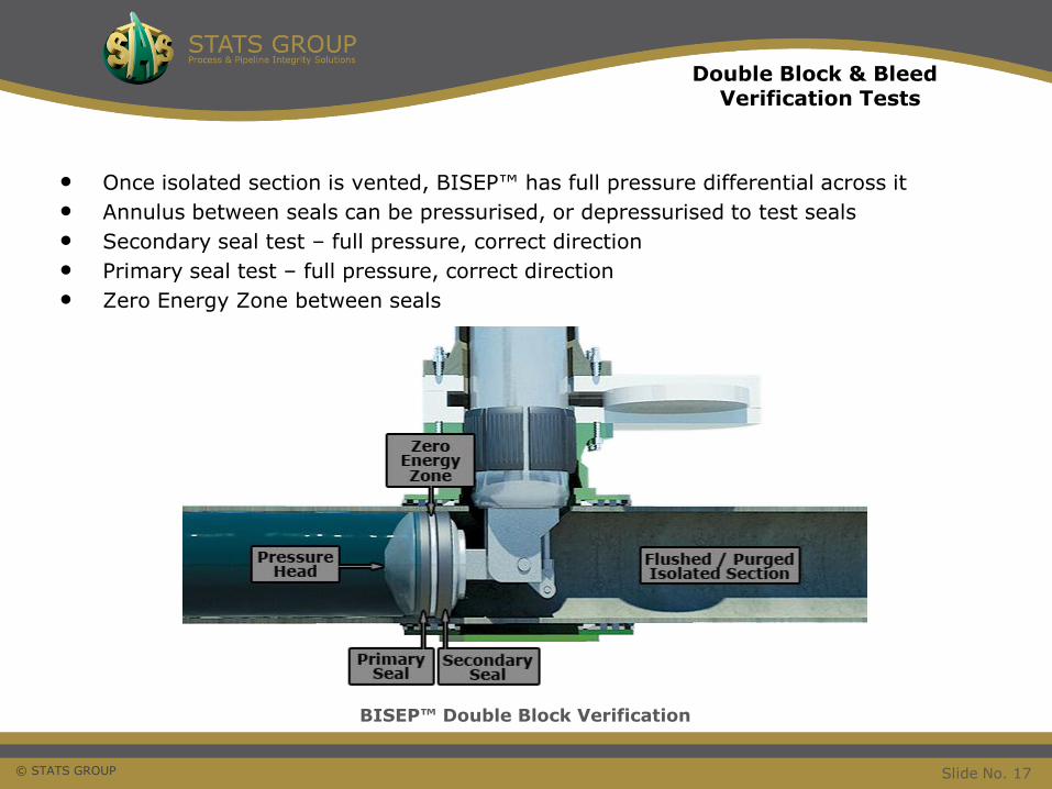
• Once isolated section is vented, BISEP™ has full pressure differential across it
• Annulus between seals can be pressurised, or depressurised to test seals
• Secondary seal test – full pressure, correct direction
• Primary seal test – full pressure, correct direction
• Zero Energy Zone between seals
BISEP™ Double Block Verification
Double Block & BleedVerification Tests
Slide No. 17
© STATS GROUP
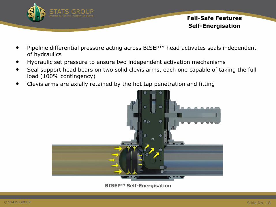
• Pipeline differential pressure acting across BISEP™ head activates seals independent of hydraulics
• Hydraulic set pressure to ensure two independent activation mechanisms
• Seal support head bears on two solid clevis arms, each one capable of taking the full load (100% contingency)
• Clevis arms are axially retained by the hot tap penetration and fitting
BISEP™ Self-Energisation
Fail-Safe Features
Self-Energisation
Slide No. 18
© STATS GROUP
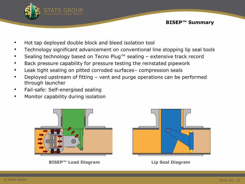
• Hot tap deployed double block and bleed isolation tool
• Technology significant advancement on conventional line stopping lip seal tools
• Sealing technology based on Tecno Plug™ sealing – extensive track record
• Back pressure capability for pressure testing the reinstated pipework
• Leak tight sealing on pitted corroded surfaces– compression seals
• Deployed upstream of fitting – vent and purge operations can be performed through launcher
• Fail-safe: Self-energised sealing
• Monitor capability during isolation
BISEP™ Load Diagram
BISEP™ Summary
Lip Seal Diagram
Slide No. 19
© STATS GROUP
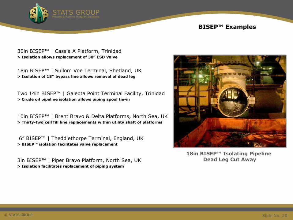
30in BISEP™ | Cassia A Platform, Trinidad> Isolation allows replacement of 30” ESD Valve
18in BISEP™ | Sullom Voe Terminal, Shetland, UK> Isolation of 18’’ bypass line allows removal of dead leg
Two 14in BISEP™ | Galeota Point Terminal Facility, Trinidad > Crude oil pipeline isolation allows piping spool tie-in
10in BISEP™ | Brent Bravo & Delta Platforms, North Sea, UK> Thirty-two cell fill line replacements within utility shaft of platforms
6” BISEP™ | Theddlethorpe Terminal, England, UK> BISEP™ isolation facilitates valve replacement
3in BISEP™ | Piper Bravo Platform, North Sea, UK > Isolation facilitates replacement of piping system
18in BISEP™ Isolating Pipeline Dead Leg Cut Away
BISEP™ Examples
Slide No. 20
© STATS GROUP
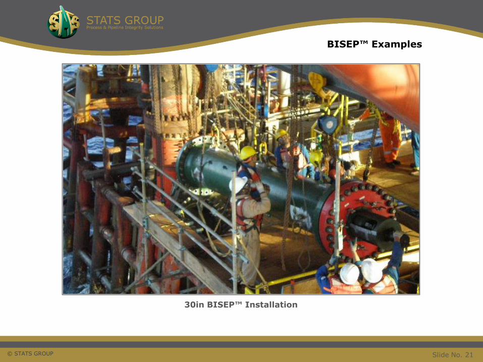
30in BISEP™ Installation
BISEP™ Examples
Slide No. 21
© STATS GROUP 22
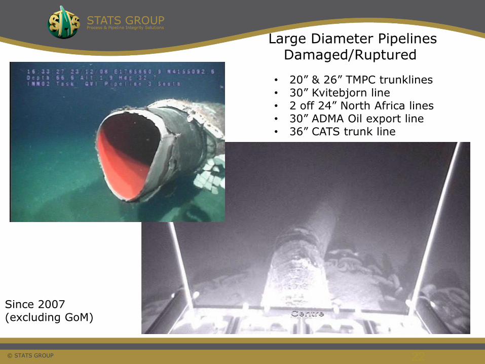
• 20” & 26” TMPC trunklines • 30” Kvitebjorn line• 2 off 24” North Africa lines• 30” ADMA Oil export line• 36” CATS trunk line
Large Diameter PipelinesDamaged/Ruptured
Since 2007 (excluding GoM)
© STATS GROUP
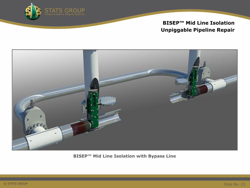
BISEP™ Mid Line Isolation
Unpiggable Pipeline Repair
BISEP™ Mid Line Isolation with Bypass Line
Slide No. 23
© STATS GROUP
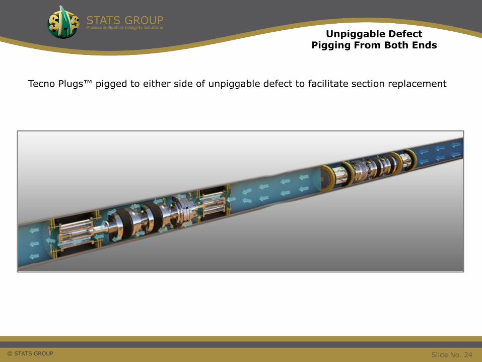
Unpiggable DefectPigging From Both Ends
Tecno Plugs™ pigged to either side of unpiggable defect to facilitate section replacement
Slide No. 24
© STATS GROUP
Thank You For Your Attention
Animations
&
Questions
BISEP™ and Tecno Plug™ are trade marks of STATS (UK) Ltd
Slide No. 25