pipeline working group support and off-board …pipeline working group support and off-board...
TRANSCRIPT
Pipeline Working Group Support and Off-Board Hydrogen Storage
Development
Kevin L. Klug
Concurrent Technologies CorporationJune 11, 2008
PDP20This presentation does not contain any proprietary, confidential, or otherwise restricted information

Program Structure & Poster Organization
Hydrogen Regional InfrastructureProgram In Pennsylvania
Materials Separations& Sensors
HydrogenDelivery
Pipeline
Phase I Testing w/SRNL(Tensile)
Phase II Testingw/SRNL (J-R and Threshold)
Pipeline Working GroupRound-Robin Coordination
Composite Overwrapped Pressure Vessels(COPVs) for Off-Board Hydrogen Storage
Phase I Efforts(Weight Driven)
Phase II Efforts(Cost Driven)
Composite Coupon Testing
Serviceability Analysis
Cathodic Charging Testing
• The Hydrogen Regional Infrastructure Program in Pennsylvania consists of three tasks
• The materials task consists of pipeline and COPV subtasks
• At DOE’s request, this poster focuses only on Pipeline Working Group (PWG) and Phase II COPV efforts
2

Overview – Materials Task
• Start - September 1, 2004• Finish - January 31, 2009• 85% Complete
• Total overall* project funding– DOE share - $5,917K– Contractor share - $1,491K
• Materials task funding**– FY05: $632,560– FY06: $249,506
• Funding received in FY07: $0• Funding for FY08: $0
Timeline
Budget
• Pipeline Working Group, including:– Department of Energy– National Institute of Standards and
Technology– Oak Ridge National Laboratory– Sandia National Laboratory– Savannah River National Laboratory– University of Illinois at Urbana-Champaign
• HyPerComp Engineering, Inc.• American Society of Mechanical Engineers
Partners
Barriers MYRDDPReference
Hydrogen Embrittlement of Pipelines 3.2.4.2 D
Gaseous Hydrogen Storage CostsStorage Tank Materials and Costs
3.2.4.2 F3.2.4.2 G
• Aid PWG in obtaining critical pipeline mechanical test data in hydrogen
• COPV Cost efficiency: $500/kg (2010) and $300/kg (2015)
• COPV Volumetric efficiency: 0.030 kg/L (2010) and 0.035 kg/L (2015)
Targets
* Including the materials, separation and sensors, and hydrogen delivery tasks** This covers the entire materials task (outlined on previous slide), not just the items covered on this poster
3

Objectives – Pipeline Working Group Support
Mission Statement – Pipeline Working Group (PWG)• Develop hydrogen delivery technology that is safe, improved and
cost effective
Objective Statement – Round Robin Testing (RRT)• Verify that participating laboratories conform to the same test
procedures for tensile testing of pipeline steels in hydrogen– Coordinate and report test outcomes– Develop understanding of any differences that arise in measured properties
CTC’s Objectives• Support tensile RRT as described on next slide• Transition to fatigue testing round robin
4

Approach – Pipeline Working Group Support
Communication• Interface with other members of PWG via email, teleconference
and semi-annual on-site meetings
Material Procurement and Specimen Preparation• Lead pipeline material selection, procurement and inspection
– Initial focus on tensile testing of X52 and X100 pipeline steels
• Coordinate and down-select specimen geometry that can be accommodated by all participating laboratories
• Facilitate machining, inspection, documentation and distributionof all relevant specimens
• Work with testing participants to define test matrix
Verification and Documentation• Monitor testing at participating laboratories• Document and report RRT results to PWG 5

Material Selection, Procurement and Inspection
Approximately 40′ of 12.75″ OD, 0.5″thick, electric resistance welded (ERW) X52 pipeline was procured from Oregon Steel Mill’s TubularCamrose facility in Alberta, Canada
6
API 5L X52 Steel
A strip of material measuring approximately 6′ long and 4″ wide
was supplied from a 30-36″ diameter X100 pipe by NIST-Boulder
API 5L X100 Steel

Down-Selected Tensile Specimen Geometry
• A sub-sized, cylindrical geometry conforming to ASTM E-8 was selected as a common specimen for each lab to test
0.750 ± 0.020
0.400 ± 0.020
5/32 R min.
1/4-20 threads(2 places)
0.160 ± 0.003 D
Note: may be tapered so that diameter at center positionof gauge length is 0.0016 in less than end positions
0.500 ± 0.020
All dimensions are in inches.Maximum RMS surface roughness = 8 microinches
Drawing courtesy of Brian Somerday (SNL) 7
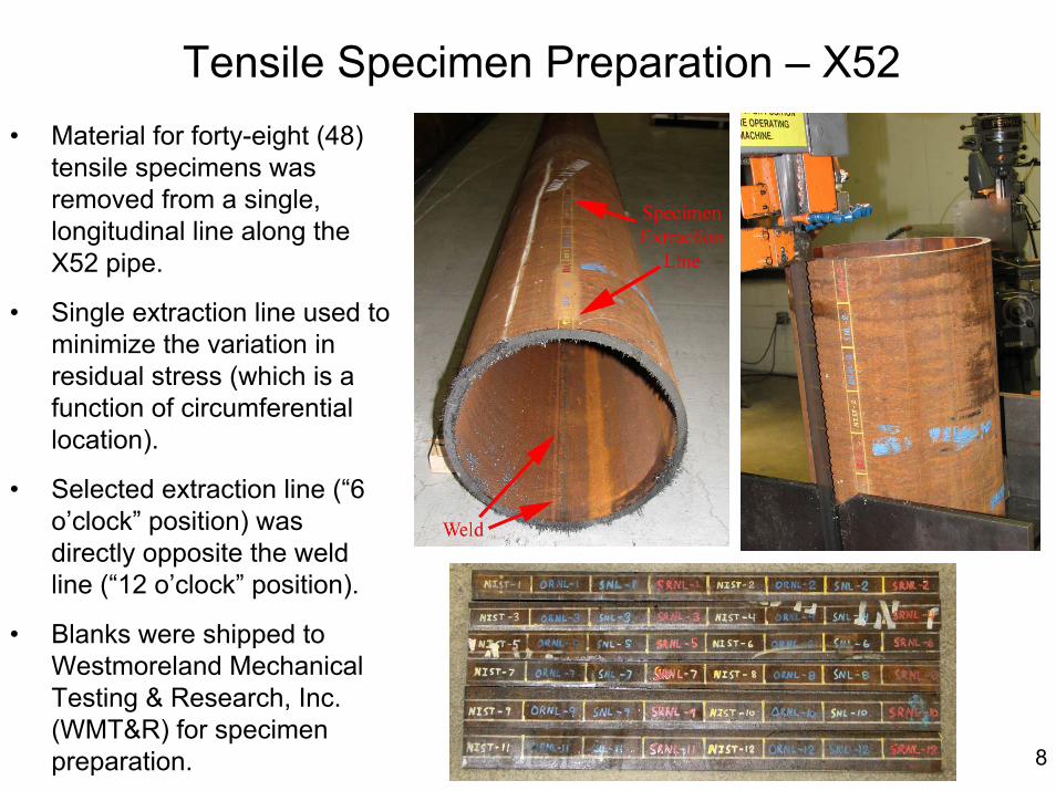
Tensile Specimen Preparation – X52
8
• Material for forty-eight (48) tensile specimens was removed from a single, longitudinal line along the X52 pipe.
• Single extraction line used to minimize the variation in residual stress (which is a function of circumferential location).
• Selected extraction line (“6 o’clock” position) was directly opposite the weld line (“12 o’clock” position).
• Blanks were shipped to Westmoreland Mechanical Testing & Research, Inc. (WMT&R) for specimen preparation.

Tensile Specimen Preparation – X100
• All flame cut edges were avoided
• Specimens were arranged in rows of thirteen, such that each column included one specimen for each of the four testing labs
• The specimen blanks were shipped to WMT&R as a single piece
9

Tensile Test Matrix
• Same test matrix will be used for both X52 and X100 specimens
10
Test Lab Extraction Location Test Atmosphere Test Pressure (psi) Test Temperature (°F) # SpecimensAir 14.7 (i.e., 1 atm) RT 3
Helium TBD (same as H2) RT 3Hydrogen TBD (same as He) RT 3
3Air 14.7 (i.e., 1 atm) RT 3
Helium TBD (same as H2) RT 3Hydrogen TBD (same as He) RT 3
3Air 14.7 (i.e., 1 atm) RT 3
Helium TBD (same as H2) RT 3Hydrogen TBD (same as He) RT 3
3
TBD - Spare specimens
Base metalopposite weld
NIST-B = NIST facility in Boulder, CO, which will test via high-pressure hydrogen gasNIST-G = NIST facility in Gaithersburg, MD, which will test via cathodic hydrogen charging
Will use cathodic charging to introduce hydrogen to the specimens. Exact conditions TBD. 9
SNL
TBD - Spare specimens
NIST-G
TBD - Spare specimens
NIST-B Base metalopposite weld
Base metalopposite weld
Base metalopposite weld
ORNL

RRT Schedule
11

Summary – Pipeline Working Group Support
• X52 and X100 pipeline materials were obtained• A labeling convention was developed to track tensile specimens• CTC removed tensile specimen blanks from the X52 and X100
feedstocks• WMT&R machined the tensile specimens• After confirming their geometry and surface roughness, CTC
shipped the tensile specimens to each laboratory
12
Future Work – Pipeline Working Group Support• CTC will monitor the RRT activities at each lab and report the
cumulative results• CTC will machine fatigue specimens in support of the next planned
PWG activity

Objectives – Composite Overwrapped Pressure Vessels (COPVs) for Off-Board Hydrogen Storage
Technical Targets• Produce and test cost-efficient prototype vessel for off-board
hydrogen storage, with the following goals:1. Cost efficiency: $/kg H2 stored
• $500/kg (2010) and $300/kg (2015)2. Volumetric efficiency: kg H2/L of storage volume
• 0.030 kg/L (2010) and 0.035 kg/L (2015) 3. Weight efficiency*: mass H2 stored at service pressure/ mass of COPV
• 6 % (2010) and 9 % (2015)
Implications• Reducing the cost of COPVs will aid in meeting overall
refueling station and similar off-board storage infrastructure cost targets
* Not a specific goal for off-board hydrogen storage; listed for information only. 13

Approach – COPVs for Off-Board Hydrogen Storage
COPV Design• Leverage lessons learned during Phase I (weight-driven) COPV
design effort for Phase II (cost-driven) design effort• Develop and execute a computer program to explore the effects raw
materials, tank geometry and pressure have on storage tank purchased capital cost, volumetric efficiency and weight efficiency
• Assess the cost and volumetric capacity of the COPV design
COPV Production• Produce prototype, Type II COPVs
Evaluate Prototypes• Burst test four prototype COPVs• Cycle fatigue test four prototype COPVs• Drop (i.e., damage) and then cycle fatigue test four prototype
COPVS 14
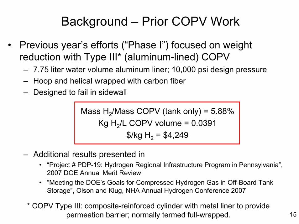
• Previous year’s efforts (“Phase I”) focused on weight reduction with Type III* (aluminum-lined) COPV– 7.75 liter water volume aluminum liner; 10,000 psi design pressure– Hoop and helical wrapped with carbon fiber– Designed to fail in sidewall
Mass H2/Mass COPV (tank only) = 5.88%Kg H2/L COPV volume = 0.0391
$/kg H2 = $4,249
– Additional results presented in• “Project # PDP-19: Hydrogen Regional Infrastructure Program in Pennsylvania”,
2007 DOE Annual Merit Review• “Meeting the DOE’s Goals for Compressed Hydrogen Gas in Off-Board Tank
Storage”, Olson and Klug, NHA Annual Hydrogen Conference 2007
Background – Prior COPV Work
15* COPV Type III: composite-reinforced cylinder with metal liner to provide
permeation barrier; normally termed full-wrapped.

Type II* COPV Design• Cost reduction was primary goal of this phase• Liner options for prototypes limited due to small quantities
required, limited budget and short-term schedule• Best available option was high-strength chromium
molybdenum (34CrM04) steel SCUBA tank– Made by FABER (Italy)– Two “dog-bone” specimens cut from a liner
Yield Strength UTS Elongation Reduction of Area122.8 ksi 141.1 ksi 14 % 51 %
Performance of liner in hydrogen is currently unknown, but high strength suggests
embrittlement concerns. For scale-up, a more suitable alloy should be selected and
incorporated in overall COPV design.16
* COPV Type II: composite-reinforced cylinder with load-sharing metal liner; normally termed hoop-wrapped.

Type II COPV Design (continued)
• Fiber: commercial grade Toray T700 12K (carbon fiber)• Resin: Epon 828 (epoxy resin)• COPV Design Details:
– Volume: 15 L– Mass: 17.95 kg– Service Pressure: 6,700 psi
• A total of 14 Type II COPVs were produced– 4 each were hydrostatically burst tested, fatigue cycle tested and
fatigue cycle tested after impact– 2 were held in reserve
17All hydrogen storage tanks were manufactured
by HEI at their Brigham City, UT facility
$/kg H2 = $642kg H2/L COPV volume = 0.0292Mass H2/Mass COPV = 2.46%
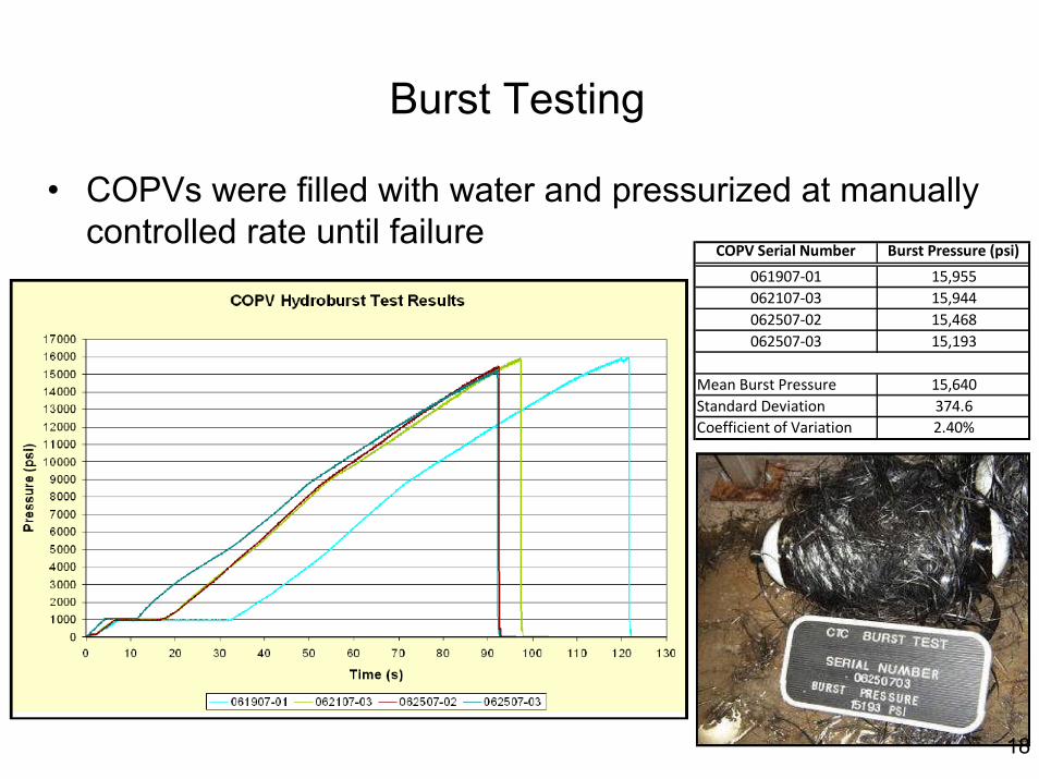
Burst Testing
COPV Serial Number Burst Pressure (psi)
061907‐01 15,955062107‐03 15,944062507‐02 15,468062507‐03 15,193
Mean Burst Pressure 15,640Standard Deviation 374.6Coefficient of Variation 2.40%
• COPVs were filled with water and pressurized at manually controlled rate until failure
18
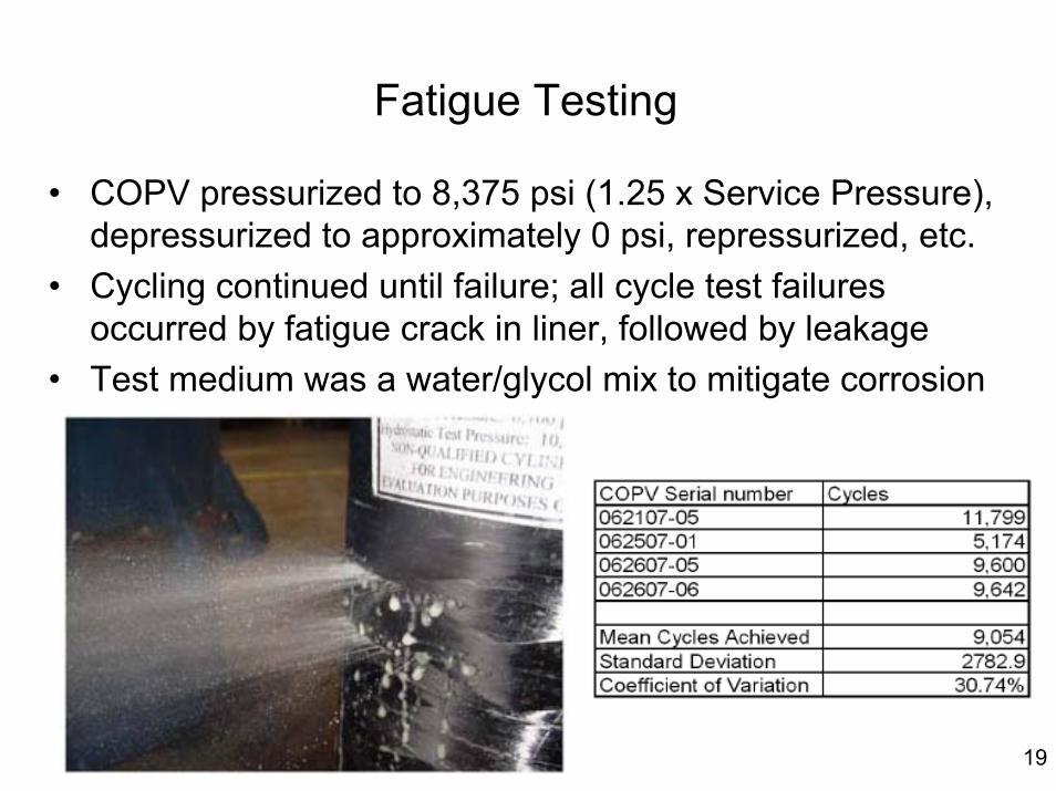
Fatigue Testing
• COPV pressurized to 8,375 psi (1.25 x Service Pressure), depressurized to approximately 0 psi, repressurized, etc.
• Cycling continued until failure; all cycle test failures occurred by fatigue crack in liner, followed by leakage
• Test medium was a water/glycol mix to mitigate corrosion
19

Post-Drop Fatigue Testing
• Each of four COPVs was dropped at various vertical, horizontal and offset angles– Cylinders were dropped 72 inches onto concrete
• After dropping, each COPV was subsequently fatigue tested using previously described procedure
72″
Concrete Impact Surface
20

Summary – COPV for Off-Board Hydrogen Storage• Prior (Phase I) effort focused on weight reduction• Current (Phase II) effort focused on cost reduction• 15 L, Type II COPV was designed and built
– Chrome-molybdenum steel SCUBA tank liner– Toray T700 12K carbon fiber– Epon 828 resin
• Prototypes approached cost and volume efficiency targets– $/kg H2 = $642; (DOE 2010 target = $500/kg )– kg H2/L COPV volume = 0.0292; (DOE 2010 target = 0.030 kg/L)
• 4 COPVs each subjected to burst, cycle and post-drop cycle testing– Mean burst pressure = 15,640 psi– Mean fatigue = 9,054 cycles @ 8,375 psi– Mean post-drop fatigue = 7,730 cycles @ 8,375 psi
21
Future Work – COPV for Off-Board Hydrogen Storage• Future efforts are not currently funded, but should:– Demonstrate scaled-up COPV– Include optimized liners (alloy, wall thickness, dome thickness, etc.)