standard pipeline materials and construction · pdf filestandard pipeline materials and...
TRANSCRIPT

STANDARD PIPELINE MATERIALS AND CONSTRUCTION SPECIFICATIONS
MAY 2013
- i -
TABLE OF CONTENTS FOR SPECIFICATIONS - MATERIALS
MAY 2013 1 - GENERAL 2 - DEFINITIONS 3 - PIPE 3.1 General 3.2 Flanged Ductile Iron Pipe 3.3 Ductile Iron Pipe, 4” – 54” 3.4 Prestressed Concrete Pressure Pipe 3.5 PVC Pipe, 2” and 3” 3.6 Copper Pipe, ¾” thru 2” 3.7 Polyethylene Service Tubing 3.8 Smooth Wall Steel Encasement Pipe 3.9 PVC Encasement Pipe 3.10 Encasement Pipe for Sanitary Sewer Crossings 4 - FITTINGS 4.1 Iron Fittings 4.2 Reinforced Concrete Fittings 4.3 Service Fittings 4.4 Displacement Type Water Meters, 5/8” thru 2” 4.5 Pressure Reducing Valves 5 - VALVES 5.1 Gate Valves – Double Disc – 14” and Larger 5.2 Gate Valves – Resilient Seat – 2” 5.3 Gate Valves – Resilient Seat – 3” thru 12” 5.4 Gate Valves – Resilient Seat – 14” thru 24” 5.5 Butterfly Valves 5.6 Air Release Valves 5.7 Combination Air Valves 6 - VALVE BOXES AND OPERATOR NUT EXTENSIONS 7 - METER BOXES AND LIDS 7.1 Meter Boxes (round) for 5/8” thru 1” Meter Settings 7.2 Meter Boxes (round) for 1 ½”, 2”, 3”, and 4” Meter Settings 8 - FIRE HYDRANTS 9 - POLYETHYLENE TUBING MATERIAL FOR PIPE ENCASEMENT 10 - TRACE WIRE FOR NON-METALLIC PIPE
Material Specification - Page 1 of 22
SPECIFICATION – MATERIALS
MAY 2013
1. GENERAL 1.1 These specifications are intended to set a standard of quality and design for all materials used in
the construction of water mains and appurtenances. Specifications for material not included in these specifications shall be included in other specifications or plans and will be furnished on request. These general and detailed specifications are subject to revision from one project to another. The CONTRACTOR shall make himself familiar with the current revision.
1.2 Central Arkansas Water must approve all material prior to installation. 1.3 All material must be of domestic manufacture and in accordance with these standards. Foreign
made materials (i.e., pipe, fittings, tapping sleeves, valve boxes, etc.) are strictly prohibited. 1.4 Any reference to specifications published by other agencies shall refer to the latest edition or
revision of such specifications as of the date of advertising for bids. 1.5 Items of materials and/or construction work not specifically addressed herein, but nonetheless
required for a complete, operating, and acceptable installation of the work, shall be considered subsidiary to the principal bid item requiring such materials and/or work and the cost thereof shall be considered to be included in the bid price for the principal items.
2. DEFINITIONS
2.1 The term "as specified" shall mean as specified by the Central Arkansas Water in plans, proposals, other specifications, and written or oral instructions
2.2 The term "or equal" shall mean that the proposed material or item shall perform adequately the
duties imposed by the general design and is of the same or equal design, substance, and function to that specified by using the name of a product manufacturer, or vendor. Central Arkansas Water shall make final approval of such items or materials.
2.3 Abbreviations used throughout these specifications have meanings as follows: AASHTO American Assoc. of State Highway & Transportation Officials AC Asbestos Cement ANSI American National Standards Institute ASTM American Society for Testing Materials AWWA American Water Works Association (Latest Revision) CF Copper Flare CI Gray Cast Iron CS or CC AWWA (Mueller Corporation Stop) Thread DI Ductile Iron DFT Dry Film Thickness FIP Female Iron Pipe FCF Female Copper Flare IP Iron Pipe MIP Male Iron Pipe
Material Specification - Page 2 of 22
PSI Pounds Per Square Inch PVC Polyvinyl Chloride SSPC Steel Structures Painting Council PJ Pack Joint (Compression fitting) CTS Copper Tubing Size DP Double / Dual Purpose
3. PIPE 3.1 All pipe furnished shall be designed for the distribution of potable water. All pipe furnished shall
be of domestic manufacture and be in compliance with NSF 61. Lubricant furnished for lubricating joins shall be non-toxic, shall not support the growth of bacteria, shall have no deteriorating effects on the gasket or pipe material, and shall not impart taste or odor to the water. The lubricant container shall be labeled with the manufacturers' name. No pipe will be accepted that has been contaminated with diesel exhaust or any other contaminant.
3.2 Flanged Ductile Iron Pipe The pipe shall have a cement mortar lining and seal coat in accordance with ANSI A21.4
(AWWA C104) and NSF 61. The minimum thickness class for flanged pipe shall be Class 53 unless otherwise specified. The pipe and flanges shall conform to ANSI A21.15 (AWWA C115), Class 250-psi. Drilling shall conform to ANSI B16.1, Class 125 flange. The flange gasket shall be high quality molded SBR rubber with properties matching ANSI/AWWA C111/A21.11 and shall meet the description of “Specially Designed Gaskets” shown in the Appendices of AWWA C110, C111, and C115 or approved equal.
3.3 Ductile Iron Pipe, 4" - 54" 3.3.1 Pipe shall conform to ANSI A21.51 (AWWA C151) and shall have a cement mortar
lining and seal coat conforming to ANSI A21.4 (AWWA C104) and NSF 61. Joints shall conform to ANSI A21.11 (AWWA C111) and may be mechanical joint or push-on joint unless otherwise specified. Gaskets shall be manufactured in the United States and/or Costa Rica. The minimum class of D.I. pipe shall be THICKNESS CLASS 50 unless otherwise specified. All ductile iron shall be encased in polyethylene (polywrapped) upon installation (See Section 21 of the Construction Specifications for specifics). All ductile iron mains shall end with a full joint of mechanical joint pipe with a mechanical joint plug and anchor collar.
3.3.2 The following manufacturers are approved for push-on, mechanical joint, and flanged
joint ductile iron pipe: American Pipe Griffin Pipe McWane Pipe U.S. Pipe 3.3.3 The following manufacturers are approved for restrained joint ductile iron pipe: American Pipe – FLEX-RING, LOK-RING, & FLEX-LOK BALL JT. Griffin Pipe – SNAP-LOK and SNAP-LOK RIVER CROSSING U.S. Pipe – TR-FLEX and USI-FLEX BALL JT. FAST-GRIP and FIELD-LOK gasket restrained joints are NOT
acceptable restrained joints unless so indicated in the Bid Schedule. Mechanical
Material Specification - Page 3 of 22
Joint and/or Mechanical Joint with Mega-lug retainer glands are NOT acceptable restrained joints unless so indicated in the Bid Schedule.
3.3.3.1 When restrained joint ductile iron pipe is specified on a project, the fittings shall
be of the restrained joint design as the restrained joint system used on the pipe. 3.4 Prestressed Concrete Pressure Pipe 3.4.1 The pipe shall conform to AWWA C301 and be the lined-cylinder or embedded-cylinder
type as specified. If not specified by type, the type outlined in Section 1.3 AWWA C301 for the various size ranges shall be furnished unless otherwise specified. The minimum working pressure shall be 200-psi and the maximum length shall be twenty (20) feet.
3.4.2 The pipe shall be designed to withstand live loads at least equal to AASHTO H20
loading in combination with earth loads produced by earth cover under the conditions described below:
3.4.2.1 Earth cover and bedding conditions shown in the plans or construction
specifications. For purposes of computing earth loads, the cover shall not be less than six (6) feet
3.4.2.2 When not shown in the Plans or Construction Specifications, the earth loads shall be based on eight (8) feet of cover and the live loads shall be based on two (2) feet of cover. Bedding shall be considered "ordinary" as defined in Section 3.2.2.1 AWWA C301.
3.4.3 All steel surfaces, which are not imbedded in concrete at the place of manufacture, shall
be protected by a heavy zinc coating. The coating shall conform to either of the following:
3.4.3.1 Metalized or inorganic zinc coating equal to that provided by the Price Brothers
Company or Gifford-Hill American, Inc. 3.4.3.2 At least one heavy coat of Dimetcote E-Z Inorganic Zinc Primer, paintbrush or
spray applied. The surfaces to be coated shall be cleaned and degreased before application of the zinc primer.
3.4.4 Concrete for the core of pipe shall be made by using natural aggregate (aggregates such
as limestone are unacceptable). 3.5 PVC Pipe, 2” through 12”
3.5.1 Polyvinyl Chloride Pipe shall be made from Type 1, Grade 1 or Grade 2, Polyvinyl
Chloride Plastic conforming to ASTM D1784 and CS-256. 3.5.2 The pipe shall conform to ASTM D2241 as it applies to Type 1, Grade 1 or Grade 2,
Polyvinyl Chloride Plastic, SDR 17 PRESSURE CLASS 250. 3.5.3 The joints shall be designed so that the pipe and fittings may be connected on the job
without the use of glue or adhesive or any special equipment. The pipe and fittings shall have a push-on joint consisting of a single wire ring reinforced rubber gasket. The gasket and the annular recess shall be so designed and shaped that the gasket is locked in place against displacement as the joint is assembled. Gasket dimensions shall be in accordance
Material Specification - Page 4 of 22
with manufacturers' standard design dimensions and tolerances and shall be of such size and shape as to provide an adequate compressive force against the plain end and socket after assembly to effect a positive seal under all combinations of joint and gasket tolerances. Gaskets shall be vulcanized natural or vulcanized synthetic rubber. No reclaimed rubber shall be used. The joint shall be designed to withstand the same pressures as required for the pipe. The joint shall be designed so as to provide for the thermal expansion or contraction experienced with a temperature change of at least 75F.
3.5.4 The pipe may be furnished in manufacturers' standard lengths. 3.5.5 The pipe shall conform to the specifications 14 and 61 of the National Sanitation
Foundation Testing Laboratories, Ann Arbor, Michigan. 3.5.6 As a minimum, the pipe and fittings shall have the following data applied to each piece: 3.5.6.1 Nominal Size 3.5.6.2 Type of Material 3.5.6.3 SDR or Class 3.5.6.4 Manufacturer 3.5.6.5 NSF (National Sanitation Foundation seal of approval) 3.5.7 SDR 17 pipe shall conform to the above specifications.
3.5.7.1 Only the following manufacturers are acceptable:
Diamond North American
J.M. Eagle Vinyl-Plex Vulcan Plastics CertainTeed, including Certa-Lok Yelomine Northern Pipe Products 3.5.8 Fittings shall be push-joint Ductile Iron or epoxy coated steel coupling, Smith Blair 411
or equal. 3.5.9 4” through 12” PVC pipe is only allowed in designated locations outside the “Extra
Territorial Jurisdiction” areas of Pulaski County. 3.5.10 Do not use PVC pipe when the working pressure exceeds 125 psi. 3.6 Copper Pipe, 3/4" - 2" 3.6.1 Copper pipe shall be Type "K", soft tempered, seamless, for underground installation, in
accordance with ASTM B88 and Federal Specifications WW-T-799. Copper pipe shall meet or better NSF-61 requirements.
3.7 Polyethylene Service Tubing – NOT ALLOWED FOR PERMANENT PLACEMENT 3.7.1 Polyethylene service tubing ( 1”, SDR 9 min.) may only be used for temporary
construction items, such as temporary blowoff, sampling point, or any other item
Material Specification - Page 5 of 22
approved by the Engineer. ANY POLYETHYLENE SERVICE TUBING INSTALLED SHALL BE COMPLETELY DISCONNECTED FROM THE SYSTEM AND THE TUBING SHALL BE REMOVED FROM THE GROUND PRIOR TO PROJECT APPROVAL. ANY TAP ON A MAIN FOR USE OF HDPE TUBING SHALL BE 1” OR LARGER; direct tap with corporation stop on ductile iron pipe through 24” DIP; saddle tap with corporation stop on PVC pipe or DIP larger than 24” diameter.
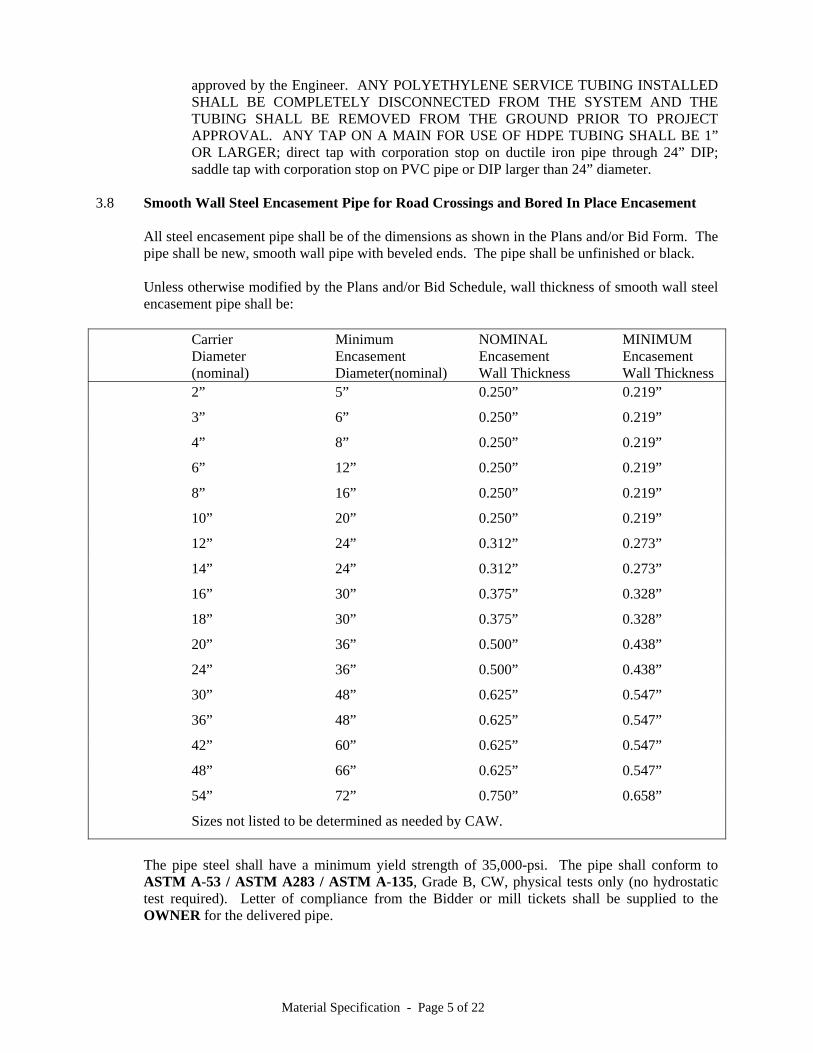
3.8 Smooth Wall Steel Encasement Pipe for Road Crossings and Bored In Place Encasement All steel encasement pipe shall be of the dimensions as shown in the Plans and/or Bid Form. The
pipe shall be new, smooth wall pipe with beveled ends. The pipe shall be unfinished or black. Unless otherwise modified by the Plans and/or Bid Schedule, wall thickness of smooth wall steel
encasement pipe shall be: Carrier Minimum NOMINAL MINIMUM Diameter Encasement Encasement Encasement (nominal) Diameter(nominal) Wall Thickness Wall Thickness 2” 5” 0.250” 0.219”
3” 6” 0.250” 0.219”
4” 8” 0.250” 0.219”
6” 12” 0.250” 0.219”
8” 16” 0.250” 0.219”
10” 20” 0.250” 0.219”
12” 24” 0.312” 0.273”
14” 24” 0.312” 0.273”
16” 30” 0.375” 0.328”
18” 30” 0.375” 0.328”
20” 36” 0.500” 0.438”
24” 36” 0.500” 0.438”
30” 48” 0.625” 0.547”
36” 48” 0.625” 0.547”
42” 60” 0.625” 0.547”
48” 66” 0.625” 0.547”
54” 72” 0.750” 0.658”
Sizes not listed to be determined as needed by CAW.
The pipe steel shall have a minimum yield strength of 35,000-psi. The pipe shall conform to
ASTM A-53 / ASTM A283 / ASTM A-135, Grade B, CW, physical tests only (no hydrostatic test required). Letter of compliance from the Bidder or mill tickets shall be supplied to the OWNER for the delivered pipe.
Material Specification - Page 6 of 22
All pipe less than or equal to 24-inch diameter shall be Type E (electric-resistance welded, Grade B) or Type S (seamless, Grade B). All pipe greater than or equal to 26-inch diameter shall be Type E (electric-resistance welded, Grade B) or Type S (seamless, Grade B) or Rolled Plate (straight seam, Grade B material) or Spiral Welded. Rolled plate pipe shall have only one longitudinal seam per section; sections shall be no shorter than 80-inches long except one short piece will be allowed to complete a specified joint length.
3.8.1 Spacers will be required on water pipes four (4) inches and larger. The spacers shall be
fusion bonded epoxy coated carbon steel or T-304 stainless steel casing spacers Model SI or SSI as manufactured by Advance Products and Systems, Inc., of Lafayette, Louisiana, or approved equal.
3.8.2 A Series 300 stainless steel wire rope cable, 3/8” diameter, shall be provided threaded through the encasement pipe along with the carrier pipes of 6-inch diameter and larger. Splices should be avoided, but if necessary shall be made with Series 300 stainless steel wire rope cable clamps.
3.9 PVC Encasement Pipe (when specified or directed for use) All PVC encasement pipe shall conform to the polyvinyl chloride pipe specifications contained in
Section 3.5 herein, SDR 17 Pressure Class 250 or C900 DR 18, of the nominal diameter as shown in the Plans or as directed by the Engineer.
3.9.1 Spacers will be required on water pipes four (4) inches and larger. The spacers shall be
fusion bonded epoxy coated carbon steel or T-304 stainless steel casing spacers Model SI or SSI as manufactured by Advance Products and Systems, Inc., of Lafayette, Louisiana, or approved equal.
3.10 Encasement Pipe for Sanitary Sewer Main Crossings Encasement pipe for water lines crossing over a sanitary sewer main with less than eighteen (18)
inches of clearance or for water lines crossing under a sanitary sewer main shall be either of the following at the CONTRACTOR’S option: (a) smooth wall steel pipe, ¼-inch wall thickness or better, (b) solid wall PVC water pipe, SDR 26 wall thickness or better, (c) aluminized corrugated metal pipe, 12-gauge wall thickness or better, (d) corrugated polyethylene storm drain pipe, HANCOR HI-Q or equal, or (e) solid wall polyethylene pipe, SDR 26 wall thickness or better. PVC and polyethylene pipes shall be encapsulated with crushed stone bedding. Encasement pipe shall be placed as a twenty (20) foot long piece. Any joint in the twenty foot length shall be welded or mechanical in nature and shall be watertight. The ends of the encasement pipe shall be sealed watertight. Typically the water line shall be encased. Upon approval by the ENGINEER, the sanitary sewer main may be encased in lieu of encasing the water line.
4. FITTINGS 4.1 Iron Fittings
Iron Fittings 4” and larger shall be designed for a working pressure of at least 250-psi, shall be ductile iron, and shall be of domestic manufacture. Iron Fittings shall conform to AWWA/ANSI C110/A21.10 (full bodied) or AWWA/ANSI C153/A21.53 (compact body). Unless otherwise specified in the Plans or in the Bid Schedule, fittings may be mechanical joint or push-on joint conforming to ANSI A21.11. All fittings shall be furnished with gaskets, and mechanical joint fittings shall be furnished with bolts, nuts, and iron glands. All 4” and larger fittings (except solid sleeves, plugs and caps) shall be cement mortar lined in accordance with ANSI A21.4. Two-inch
Material Specification - Page 7 of 22
and three-inch iron fittings shall be HARCO ductile iron push-on joint fittings pressure rated at 300 psi. All iron fittings shall be polywrapped upon installation (see Section 21 of the Construction Specifications for specifics).
4.1.1 Mechanical Joint Retainer Glands - shall be made from ductile iron and shall be designed
for a working pressure of at least 350-psi for 3-inch through 16-inch pipe and at least 250-psi for 18-inch through 48-inch pipe. The retainer gland shall be SERIES 1100 MEGALUG mechanical joint restraint as manufactured by EBAA IRON SALES INC or UNI-FLANGE SERIES 1400 by FORD METER BOX or DOMESTIC STARGRIP SERIES 3000 by STAR PIPE PRODUCTS. All retainer glands shall be of domestic (U.S.A.) manufacture.
4.1.2 Swivel Hydrant Adapters and Tees. Shall be designed for a working pressure of at least 250-psi and to fit standard
mechanical joint fittings (AWWA C111). One end of the swivel adapter and the branch of the tee shall be provided with a gland that may be rotated 360 degrees on the fitting. Lengths of swivel adapter shall be as specified.
4.1.3 Tapping Sleeves - (4" Tap and Larger)
Sleeves may be iron or steel. Tapping sleeves shall be designed for a working pressure of at least 175-psi and a test pressure as required for the project (225 psi or greater as required). Fabricated steel sleeves shall be Type 304 stainless steel OR carbon steel coated with high build Thermo-Set Epoxy. A test plug shall be furnished through the body for hydrostatic pressure testing on all sleeves. See Section 33.4.1 and 33.11 of the Construction Specifications for testing requirements. The outlets shall conform to ANSI B16.1, Class 125 flanges designed to accept tapping valves described herein. All bolts shall be of corrosion resistant alloy. Sleeves may be designed for a watertight seal by the use of mechanical followers or by the use of a gasket placed in a recess between the sleeve body and the pipe barrel. Only sleeves with mechanical followers or full circle gaskets may be used for full size taps. The use of other type sleeves is restricted to taps where the branch is at least one size smaller than the run.
4.1.4 Sleeves/Couplings
Sleeves shall be ductile iron with M.J. followers. Couplings shall be steel or ductile iron with gasketed ends. They shall be designed for a working pressure of at least 200-psi and a test pressure as required for the project (225 psi or greater as required) and sized to properly fit the type and class of pipe specified. All bolts shall be of corrosion resistance alloy. Carbon steel couplings shall be coated internally and externally with high build, high strength, Thermo-set Epoxy coating, 8-10 mil D.F.T. and free of holidays, or, alternately, steel couplings shall be Type 304 stainless steel.
Material Specification - Page 8 of 22
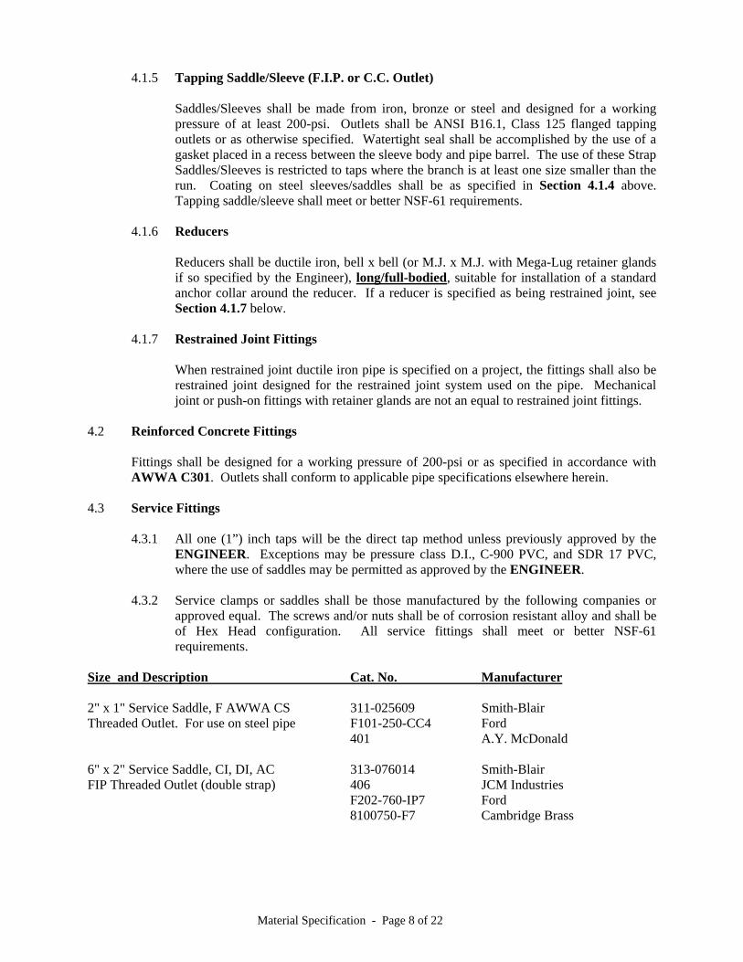
4.1.5 Tapping Saddle/Sleeve (F.I.P. or C.C. Outlet)
Saddles/Sleeves shall be made from iron, bronze or steel and designed for a working pressure of at least 200-psi. Outlets shall be ANSI B16.1, Class 125 flanged tapping outlets or as otherwise specified. Watertight seal shall be accomplished by the use of a gasket placed in a recess between the sleeve body and pipe barrel. The use of these Strap Saddles/Sleeves is restricted to taps where the branch is at least one size smaller than the run. Coating on steel sleeves/saddles shall be as specified in Section 4.1.4 above. Tapping saddle/sleeve shall meet or better NSF-61 requirements.
4.1.6 Reducers Reducers shall be ductile iron, bell x bell (or M.J. x M.J. with Mega-Lug retainer glands
if so specified by the Engineer), long/full-bodied, suitable for installation of a standard anchor collar around the reducer. If a reducer is specified as being restrained joint, see Section 4.1.7 below.
4.1.7 Restrained Joint Fittings When restrained joint ductile iron pipe is specified on a project, the fittings shall also be
restrained joint designed for the restrained joint system used on the pipe. Mechanical joint or push-on fittings with retainer glands are not an equal to restrained joint fittings.
4.2 Reinforced Concrete Fittings
Fittings shall be designed for a working pressure of 200-psi or as specified in accordance with AWWA C301. Outlets shall conform to applicable pipe specifications elsewhere herein.
4.3 Service Fittings 4.3.1 All one (1”) inch taps will be the direct tap method unless previously approved by the
ENGINEER. Exceptions may be pressure class D.I., C-900 PVC, and SDR 17 PVC, where the use of saddles may be permitted as approved by the ENGINEER.
4.3.2 Service clamps or saddles shall be those manufactured by the following companies or
approved equal. The screws and/or nuts shall be of corrosion resistant alloy and shall be of Hex Head configuration. All service fittings shall meet or better NSF-61 requirements.
Size and Description Cat. No. Manufacturer 2" x 1" Service Saddle, F AWWA CS 311-025609 Smith-Blair Threaded Outlet. For use on steel pipe F101-250-CC4 Ford 401 A.Y. McDonald 6" x 2" Service Saddle, CI, DI, AC 313-076014 Smith-Blair FIP Threaded Outlet (double strap) 406 JCM Industries F202-760-IP7 Ford 8100750-F7 Cambridge Brass

Material Specification - Page 9 of 22
8" x 2" Service Saddle, CI, DI AC 313-101014 Smith-Blair FIP Threaded Outlet (double strap) F202-979-IP7 Ford 406 JCM Industries 810-0962-F7 Cambridge Brass 10" x 2" Service Saddle, CI, DI, AC 313-121214 Smith-Blair FIP Threaded Outlet (double Strap) F202-1212-IP7 Ford 406 JCM Industries 810-1212-F7 Cambridge Brass 12" x 2" Service Saddle, CI, DI, AC 313-143214 Smith-Blair B202-1438-IP7 Ford 406 JCM Industries 810-1438-F7 Cambridge Brass
2" x 1" Bronze Service Saddle, AWWA CS H-13420 Mueller threaded outlet, for use on PVC pipe S70-204 Ford 2.375" OD 327 Smith-Blair 800-0238-F4 Cambridge Brass 3" x 1" Bronze Service Saddle, AWWA CS H-13425 Mueller threaded outlet, for use on PVC pipe S70-304 Ford 3.50" OD 327 Smith-Blair 800-0350-A4 Cambridge Brass 4" x 1" Bronze Service Saddle, AWWA CS H-13248 Mueller threaded outlet, for use on PVC pipe S70-404 Ford 4.50" OD 327 Smith-Blair 800-0450-A4 Cambridge Brass 1" x 3/4" Brass Bushing, IP threads C18-43NL Ford 72206 A.Y. McDonald 1" x 1/2" Brass Bushing, IP threads C18-14 NL Ford 72206 A.Y. McDonald 3/4" x 1/2" Brass Bushing, IP threads C18-13NL Ford 72206 A.Y. McDonald 2" & 3" Brass Nipples, length as specified, IP threads on one end, 45 deg. Bevel on other end (AWWA C800 Red Brass Pipe) 1/2", 3/4", 1", 2", 3" Brass Nipples, length as specified IP threads on each end (AWWA C800 Red Brass Pipe) 4.3.3 Corporation and curb stops shall conform to AWWA C800 (curb stops shall have a 360
deg. rotation of the Tee Head) and shall be those manufactured by the following companies or approved equal.
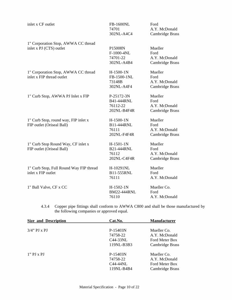
Size and Description Cat.No. Manufacturer 1" Corporation Stop, AWWA CC thread H-1500N Mueller
Material Specification - Page 10 of 22
inlet x CF outlet FB-1600NL Ford 74701 A.Y. McDonald
302NL-A4C4 Cambridge Brass 1" Corporation Stop, AWWA CC thread inlet x PJ (CTS) outlet P15008N Mueller F-1000-4NL Ford 74701-22 A.Y. McDonald 302NL-A4B4 Cambridge Brass 1" Corporation Stop, AWWA CC thread H-1500-1N Mueller inlet x FIP thread outlet FB-1500-1NL Ford 73148B A.Y. McDonald 302NL-A4F4 Cambridge Brass 1" Curb Stop, AWWA PJ Inlet x FIP P-25172-3N Mueller B41-444RNL Ford 76112-22 A.Y. McDonald 202NL-B4F4R Cambridge Brass 1" Curb Stop, round way, FIP inlet x H-1500-1N Mueller FIP outlet (Oriseal Ball) B11-444RNL Ford 76111 A.Y. McDonald 202NL-F4F4R Cambridge Brass 1" Curb Stop Round Way, CF inlet x H-1501-1N Mueller FIP outlet (Oriseal Ball) B21-444RNL Ford 76112 A.Y. McDonald 202NL-C4F4R Cambridge Brass 1" Curb Stop, Full Round Way FIP thread H-10291NL Mueller inlet x FIP outlet B11-555RNL Ford 76111 A.Y. McDonald 1" Ball Valve, CF x CC H-1502-1N Mueller Co. BM22-444RNL Ford 76110 A.Y. McDonald 4.3.4 Copper pipe fittings shall conform to AWWA C800 and shall be those manufactured by
the following companies or approved equal. Size and Description Cat.No. Manufacturer 3/4” PJ x PJ P-15403N Mueller Co.
74758-22 A.Y. McDonald C44-33NL Ford Meter Box 119NL-B3B3 Cambridge Brass
1” PJ x PJ P-15403N Mueller Co. 74758-22 A.Y. McDonald C44-44NL Ford Meter Box 119NL-B4B4 Cambridge Brass
Material Specification - Page 11 of 22
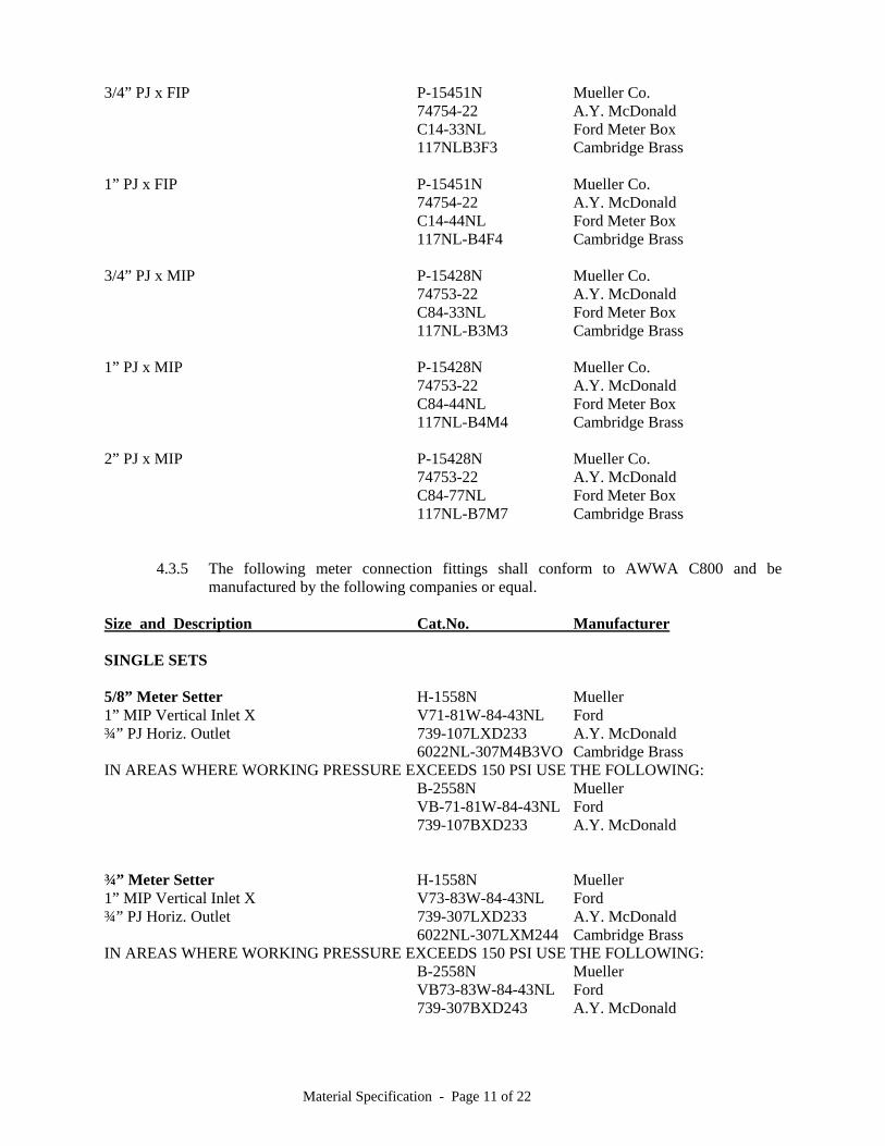
3/4” PJ x FIP P-15451N Mueller Co. 74754-22 A.Y. McDonald C14-33NL Ford Meter Box 117NLB3F3 Cambridge Brass
1” PJ x FIP P-15451N Mueller Co. 74754-22 A.Y. McDonald C14-44NL Ford Meter Box 117NL-B4F4 Cambridge Brass
3/4” PJ x MIP P-15428N Mueller Co. 74753-22 A.Y. McDonald C84-33NL Ford Meter Box 117NL-B3M3 Cambridge Brass
1” PJ x MIP P-15428N Mueller Co. 74753-22 A.Y. McDonald C84-44NL Ford Meter Box 117NL-B4M4 Cambridge Brass
2” PJ x MIP P-15428N Mueller Co. 74753-22 A.Y. McDonald C84-77NL Ford Meter Box 117NL-B7M7 Cambridge Brass
4.3.5 The following meter connection fittings shall conform to AWWA C800 and be
manufactured by the following companies or equal. Size and Description Cat.No. Manufacturer SINGLE SETS 5/8” Meter Setter H-1558N Mueller 1” MIP Vertical Inlet X V71-81W-84-43NL Ford ¾” PJ Horiz. Outlet 739-107LXD233 A.Y. McDonald 6022NL-307M4B3VO Cambridge Brass IN AREAS WHERE WORKING PRESSURE EXCEEDS 150 PSI USE THE FOLLOWING: B-2558N Mueller VB-71-81W-84-43NL Ford 739-107BXD233 A.Y. McDonald ¾” Meter Setter H-1558N Mueller 1” MIP Vertical Inlet X V73-83W-84-43NL Ford ¾” PJ Horiz. Outlet 739-307LXD233 A.Y. McDonald 6022NL-307LXM244 Cambridge Brass IN AREAS WHERE WORKING PRESSURE EXCEEDS 150 PSI USE THE FOLLOWING: B-2558N Mueller VB73-83W-84-43NL Ford 739-307BXD243 A.Y. McDonald

Material Specification - Page 12 of 22
1” Meter Setter H-1558N Mueller 1” MIP Vertical Inlet X V74-84W-84-44NL Ford 1” PJ Horiz. Outlet 739-410LXM244 A.Y. McDonald 6022NL-410M4B3VO Cambridge Brass
IN AREAS WHERE WORKING PRESSURE EXCEEDS 150 PSI USE THE FOLLOWING: B2558N Mueller VB74-84W-84-44NL Ford 739-410BXM244 A.Y. McDonald
DUAL SETS
5/8” Meter Setter H-1558 N Mueller ¾” FIP Vertical Inlet X V72-81W-14-33NL Ford ¾” PJ Horiz. Outlet 739-107LX0233 A.Y. McDonald 6022NL-107D3B3VO Cambridge Brass IN AREAS WHERE WORKING PRESSURE EXCEEDS 150 PSI USE THE FOLLOWING: B2558N Mueller VB72-81W-14-33NL Ford 739-107BXO233 A.Y.McDonald
¾” Meter Setter H-1558N Mueller ¾” FIP Vertical Inlet X V73-83W-14-33NL Ford ¾” PJ Horiz. Outlet 739-307LX0233 A.Y. McDonald 6022NL-307D3B3VO Cambridge Brass IN AREAS WHERE WORKING PRESSURE EXCEEDS 150 PSI USE THE FOLLOWING: B2558N Mueller VB73-83W-14-33NL Ford 739-307BXO233 A.Y. McDonald
1" QB Coupling PJ P-15076N Mueller L04-44SNL Ford 74776S-22 A.Y. McDonald 1" Corporation Adapter PJ P-15071N Mueller C04044NL Ford 74755-22 A.Y. McDonald 11NL-B4P4 Cambridge Brass 2" Meter Setters with 1" Bypass VV77-12B-11-77NL Ford H-1423N Mueller 6020NL-712F7F7UUB Cambridge Brass 1 1/2" Meter x 2" FIP, Angle Valve, FV13-676W-MSBNL Ford w/ Support Bracket 74604B A.Y. McDonald
Material Specification - Page 13 of 22
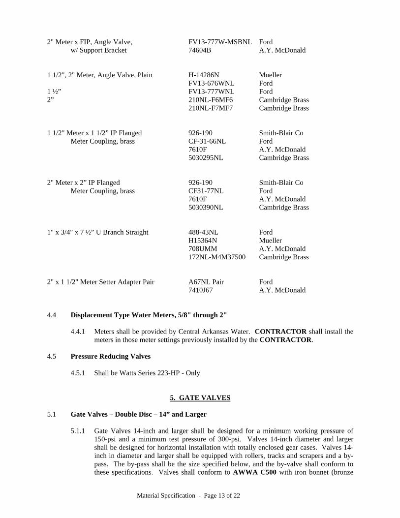
2" Meter x FIP, Angle Valve, FV13-777W-MSBNL Ford w/ Support Bracket 74604B A.Y. McDonald 1 1/2", 2" Meter, Angle Valve, Plain H-14286N Mueller FV13-676WNL Ford 1 ½” FV13-777WNL Ford 2” 210NL-F6MF6 Cambridge Brass 210NL-F7MF7 Cambridge Brass 1 1/2" Meter x 1 1/2” IP Flanged 926-190 Smith-Blair Co Meter Coupling, brass CF-31-66NL Ford 7610F A.Y. McDonald 5030295NL Cambridge Brass 2" Meter x 2” IP Flanged 926-190 Smith-Blair Co Meter Coupling, brass CF31-77NL Ford 7610F A.Y. McDonald 5030390NL Cambridge Brass 1" x 3/4" x 7 ½” U Branch Straight 488-43NL Ford H15364 N Mueller 708UMM A.Y. McDonald 172NL-M4M37500 Cambridge Brass 2" x 1 1/2" Meter Setter Adapter Pair A67NL Pair Ford 7410J67 A.Y. McDonald 4.4 Displacement Type Water Meters, 5/8" through 2" 4.4.1 Meters shall be provided by Central Arkansas Water. CONTRACTOR shall install the
meters in those meter settings previously installed by the CONTRACTOR. 4.5 Pressure Reducing Valves
4.5.1 Shall be Watts Series 223-HP - Only
5. GATE VALVES 5.1 Gate Valves – Double Disc – 14” and Larger
5.1.1 Gate Valves 14-inch and larger shall be designed for a minimum working pressure of
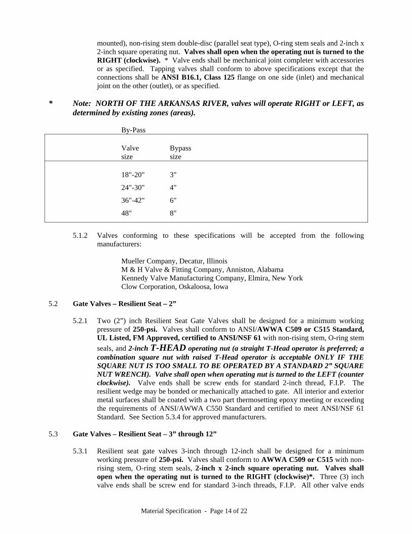
150-psi and a minimum test pressure of 300-psi. Valves 14-inch diameter and larger shall be designed for horizontal installation with totally enclosed gear cases. Valves 14-inch in diameter and larger shall be equipped with rollers, tracks and scrapers and a by-pass. The by-pass shall be the size specified below, and the by-valve shall conform to these specifications. Valves shall conform to AWWA C500 with iron bonnet (bronze
Material Specification - Page 14 of 22
mounted), non-rising stem double-disc (parallel seat type), O-ring stem seals and 2-inch x 2-inch square operating nut. Valves shall open when the operating nut is turned to the RIGHT (clockwise). * Valve ends shall be mechanical joint completer with accessories or as specified. Tapping valves shall conform to above specifications except that the connections shall be ANSI B16.1, Class 125 flange on one side (inlet) and mechanical joint on the other (outlet), or as specified.
* Note: NORTH OF THE ARKANSAS RIVER, valves will operate RIGHT or LEFT, as
determined by existing zones (areas). By-Pass Valve Bypass size size 18"-20" 3"
24"-30" 4"
36"-42" 6"
48" 8"
5.1.2 Valves conforming to these specifications will be accepted from the following
manufacturers: Mueller Company, Decatur, Illinois M & H Valve & Fitting Company, Anniston, Alabama Kennedy Valve Manufacturing Company, Elmira, New York Clow Corporation, Oskaloosa, Iowa 5.2 Gate Valves – Resilient Seat – 2” 5.2.1 Two (2”) inch Resilient Seat Gate Valves shall be designed for a minimum working
pressure of 250-psi. Valves shall conform to ANSI/AWWA C509 or C515 Standard, UL Listed, FM Approved, certified to ANSI/NSF 61 with non-rising stem, O-ring stem
seals, and 2-inch T-HEAD operating nut (a straight T-Head operator is preferred; a combination square nut with raised T-Head operator is acceptable ONLY IF THE SQUARE NUT IS TOO SMALL TO BE OPERATED BY A STANDARD 2” SQUARE NUT WRENCH). Valve shall open when operating nut is turned to the LEFT (counter clockwise). Valve ends shall be screw ends for standard 2-inch thread, F.I.P. The resilient wedge may be bonded or mechanically attached to gate. All interior and exterior metal surfaces shall be coated with a two part thermosetting epoxy meeting or exceeding the requirements of ANSI/AWWA C550 Standard and certified to meet ANSI/NSF 61 Standard. See Section 5.3.4 for approved manufacturers.
5.3 Gate Valves – Resilient Seat – 3” through 12” 5.3.1 Resilient seat gate valves 3-inch through 12-inch shall be designed for a minimum
working pressure of 250-psi. Valves shall conform to AWWA C509 or C515 with non-rising stem, O-ring stem seals, 2-inch x 2-inch square operating nut. Valves shall open when the operating nut is turned to the RIGHT (clockwise)*. Three (3) inch valve ends shall be screw end for standard 3-inch threads, F.I.P. All other valve ends
Material Specification - Page 15 of 22
shall be as specified. The resilient seat may be bonded or mechanically attached to the gate. All interior and exterior metal surfaces shall be coated with a two-part thermosetting epoxy complying with ANSI/AWWA C550.
* Note: NORTH OF THE ARKANSAS RIVER, valves will operate RIGHT or LEFT, as
determined by existing zones (areas). 5.3.2 Epoxy Coating in paragraphs 5.2.1, 5.3.1, and 5.4.1 shall be 8 mil D.F.T. and free of
holidays. 5.3.3 Tapping valves shall have full size flow way accepting standard size shell cutter.
5.3.4.1 2” through 10” – Resilient Seat Valves conforming to these specifications will be accepted from the following manufacturers:
American Flow Control (Valve & Hydrant Co.), Birmingham, Alabama Clow Corporation, Oskaloosa, Iowa Kennedy Valve Manufacturing Company, Elmira, New York Mueller Company, Decatur, Illinois U.S. Pipe & Foundry Co., Birmingham, Alabama Waterous, St. Paul, Minnesota M & H Valve and Fitting Co., AVK, American AVK Co., Fresno, CA. (2” and 3” AVK Model 35 are NOT approved)
5.3.4.2 12” – Resilient Seat Valves conforming to these specifications will be accepted from the following manufacturers: (12” valves shall have a maximum operating torque to-close of 180 ft-lbs.)
Mueller Company, Decatur, Illinois U.S. Pipe & Foundry Co., Birmingham, Alabama Clow Corporation, Oskaloosa, Iowa AVK, American AVK Co., Fresno, CA – Series 25 and Series 45 American Flow Control (Valve & Hydrant Co.), Birmingham, AL – Series 2500 5.4 Gate Valves – Resilient Seat – 14” through 24” 5.4.1 Resilient seat gate valves 14-inch through 24-inch shall be designed for a minimum
working pressure of 200-psi. Valves shall conform to AWWA C509 or C515 with non-rising stem, O-ring stem seals, theroplastic thrust washers, and 2-inch square operating nut. The disc may be gray or ductile iron, totally encapsulated with rubber, with thermoplastic bearing surfaces. Valve shall open when the operating nut is turned to the RIGHT (clockwise)*. Valve ends shall be as specified. All interior and exterior metal surfaces shall be coated with a two-part thermosetting epoxy in accordance with ANSI/AWWA C550. Valves shall have a maximum operating torque to-close of 180 ft-lbs.
* Note: NORTH OF THE ARKANSAS RIVER, valves will operate RIGHT or LEFT, as
determined by existing zones (areas).
Material Specification - Page 16 of 22
5.4.2 14” through 24” - Resilient Seat Valves conforming to these specifications will be accepted from the following manufacturers:
Mueller Company, Decatur, Illinois U.S. Pipe & Foundry Co., Birmingham, Alabama American Flow Control (Valve & Hydrant Co.), Birmingham, AL – Series 2500 Clow Corporation, Oskaloosa, Iowa 5.5 Butterfly Valves
Butterfly valves shall conform to AWWA C504. 5.5.1 Pressure Rating: butterfly valves that will be tested against or otherwise be subject to
pressures in excess of 150-psi, shall be rated for 250-psi service; butterfly valves that will not be tested against and otherwise will not be subject to pressures in excess of 150-psi, shall be rated for 150-psi service.
5.5.2 Suitable for complete buried service. Exterior of valve shall be epoxy coated.
5.5.3 Disc may be made from any of the materials as specified in AWWA C504. However,
discs made from materials other than bronze or stainless steel shall be coated with epoxy material in accordance with paragraph 5.5.10 below. All other interior surfaces which are not stainless steel or bronze shall also be coated with epoxy material.
5.5.4 Valve resilient seats shall be BUNA-N bonded into a self-retaining recess in the body or
a natural rubber molded to an 18-8, Type 304 S.S. retaining ring secured to the disc by self setting screws. If the set is attached to the disc, the mating surface to the resilient seat shall be Type 304 or 316 stainless.
5.5.5 Stainless steel shafting 5.5.6 O-Ring or split-V shaft seals 5.5.7 Bronze, nylon or Teflon bearings 5.5.8 Manual Operator totally enclosed for buried service 5.5.8.1 2-inch x 2-inch operating nut
5.5.8.2 Open RIGHT (clockwise)* * Note: NORTH OF THE ARKANSAS RIVER, valves will operate RIGHT or LEFT,
as determined by existing zones (areas). 5.5.8.3 Operators of the traveling nut type shall NOT have u-joints to the reach rods 5.5.8.4 On operators composed of worm gears, worm gears may be either bronze or
ductile iron and the worms shall be composed of hardened steel. 5.5.8.5 The operators shall satisfy the valve operating torque requirements for Class
150B valves and the operator input requirements of AWWA C-504.
Material Specification - Page 17 of 22
5.5.9 Valve ends shall be as specified. If flange ends are specified, they shall conform to Class 125, ANSI B16.1.
5.5.10 Epoxy coating for Valve Disc. Before application of coating material, all surfaces of the
disc shall be thoroughly cleaned to remove dirt, grease, oil and any other substances; all sharp angles, protrusions or irregularities which would interfere with proper coating coverage shall be removed and the entire surface grit blasted to white metal in accordance with SSPC Specification SP5 resulting in an anchor pattern of at least one (1) mil. Thermo-set epoxy materials shall be applied to the sandblasted surfaces before the white metal begins to oxidize (darken in color). The thermoset epoxy shall be approved by the Federal Food and Drug Administration for exposure to fluids for human consumption. The final film thickness shall be at least 8 mils DFT and free of holidays. The disc shall be post-cured for a sufficient period of time to assure full polymerization. Polymerization shall be checked by a direct impact test at 60-inch-lb with no cracking or chipping of the coating. The film thickness shall be checked using an accurate magnetic film thickness gauge. The entire coated surface shall be checked for holidays using a wet sponge type holiday detector. Any areas where the film thickness is found to be less than eight (8) mills or where holidays were detected shall be re-coated and re-checked. Valves shall be packed for shipment in such manner that the disc coating is protected from damage.
5.5.11 Butterfly Valves conforming to these specifications will be accepted from the
following manufacturer: Henry Pratt Company, Aurora, Illinois 150-psi butterfly valves shall be GROUNDHOG 150B series. 250-psi butterfly valves shall be TRITON HP-250 series. 5.6 Air Release Valves
5.6.1 1-inch shall be ValMatic 25.6 or as specified. 5.7 Combination Air Valve
5.7.1 1-inch shall be ValMatic 201C.2 or as specified 5.7.2 2-inch shall be ValMatic 202C.2 or as specified
6. VALVE BOXES AND OPERATOR NUT EXTENSIONS
6.1 Valve boxes shall be the 6860 series, two piece, screw type, 5 ¼-inch shaft, Item #461-S, 19inch to 22-inch extension, or screw type, 5 ¼-inch shaft, Item #562-S, 27-inch to 37-inch extension, manufactured by Tyler/Union Utilities Company or East Jordon Iron Works 8550 series 462-s(8550 1922) and 562-s(8550 2737). All valve boxes must be constructed to accept a locking lid. All drop lids shall be marked "WATER."
6.2 For valves with operator nut located five (5) feet or more deep, an operator nut extension shall be
installed. All components of the extension shall be Series 300 stainless steel. See Section 18.4 of the Construction Specifications.
6.3 A valve box alignment device shall be provided and installed for each valve box installation. The
device shall be of HDPE or Glass Filled Polypropylene construction. It shall be furnished in two pieces that will lock together under the operating nut of the valve without requiring the removal
Material Specification - Page 18 of 22
of the operating nut. The device shall not affect the operation of the valve. The device shall be the BOXLOK as manufactured by Emma Sales, LLC, AFC Alignment Ring as manufactured by American Flow Control, or approved equal.
7. METER BOXES AND LIDS 7.1 Meter Boxes (round) for 5/8” thru 1” Meter Settings
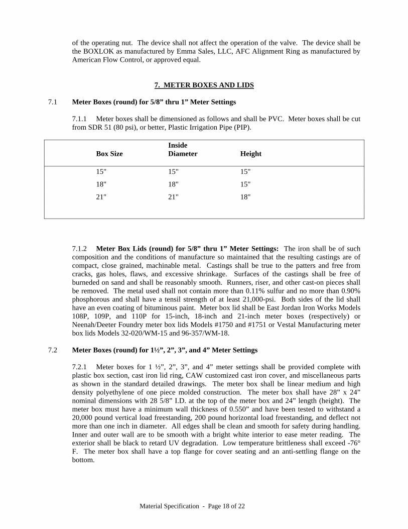
7.1.1 Meter boxes shall be dimensioned as follows and shall be PVC. Meter boxes shall be cut from SDR 51 (80 psi), or better, Plastic Irrigation Pipe (PIP).
Inside Box Size Diameter Height 15" 15" 15"
18" 18" 15"
21" 21" 18"
7.1.2 Meter Box Lids (round) for 5/8” thru 1” Meter Settings: The iron shall be of such composition and the conditions of manufacture so maintained that the resulting castings are of compact, close grained, machinable metal. Castings shall be true to the patters and free from cracks, gas holes, flaws, and excessive shrinkage. Surfaces of the castings shall be free of burneded on sand and shall be reasonably smooth. Runners, riser, and other cast-on pieces shall be removed. The metal used shall not contain more than 0.11% sulfur and no more than 0.90% phosphorous and shall have a tensil strength of at least 21,000-psi. Both sides of the lid shall have an even coating of bituminous paint. Meter box lid shall be East Jordan Iron Works Models 108P, 109P, and 110P for 15-inch, 18-inch and 21-inch meter boxes (respectively) or Neenah/Deeter Foundry meter box lids Models #1750 and #1751 or Vestal Manufacturing meter box lids Models 32-020/WM-15 and 96-357/WM-18.
7.2 Meter Boxes (round) for 1½”, 2”, 3”, and 4” Meter Settings
7.2.1 Meter boxes for 1 ½”, 2”, 3”, and 4” meter settings shall be provided complete with plastic box section, cast iron lid ring, CAW customized cast iron cover, and miscellaneous parts as shown in the standard detailed drawings. The meter box shall be linear medium and high density polyethylene of one piece molded construction. The meter box shall have 28” x 24” nominal dimensions with 28 5/8” I.D. at the top of the meter box and 24” length (height). The meter box must have a minimum wall thickness of 0.550” and have been tested to withstand a 20,000 pound vertical load freestanding, 200 pound horizontal load freestanding, and deflect not more than one inch in diameter. All edges shall be clean and smooth for safety during handling. Inner and outer wall are to be smooth with a bright white interior to ease meter reading. The exterior shall be black to retard UV degradation. Low temperature brittleness shall exceed -76° F. The meter box shall have a top flange for cover seating and an anti-settling flange on the bottom.
Material Specification - Page 19 of 22
7.2.2 For the 30” meter boxes, the customized cast iron cover (lid) shall be Product No. 32143005 and the plastic box section ( Product No. 38003024 as manufactured by DFW Plastics Inc. ); cast iron lid ring, and miscellaneous parts shall be Product No. 32243002A01 as manufactured by East Jordon Iron Works, Inc.
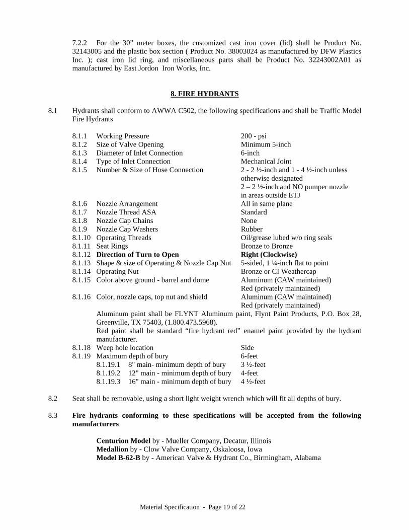
8. FIRE HYDRANTS 8.1 Hydrants shall conform to AWWA C502, the following specifications and shall be Traffic Model
Fire Hydrants
8.1.1 Working Pressure 200 - psi 8.1.2 Size of Valve Opening Minimum 5-inch
8.1.3 Diameter of Inlet Connection 6-inch 8.1.4 Type of Inlet Connection Mechanical Joint
8.1.5 Number & Size of Hose Connection 2 - 2 ½-inch and 1 - 4 ½-inch unless otherwise designated
2 – 2 ½-inch and NO pumper nozzle in areas outside ETJ
8.1.6 Nozzle Arrangement All in same plane 8.1.7 Nozzle Thread ASA Standard 8.1.8 Nozzle Cap Chains None 8.1.9 Nozzle Cap Washers Rubber 8.1.10 Operating Threads Oil/grease lubed w/o ring seals 8.1.11 Seat Rings Bronze to Bronze 8.1.12 Direction of Turn to Open Right (Clockwise) 8.1.13 Shape & size of Operating & Nozzle Cap Nut 5-sided, 1 ¼-inch flat to point 8.1.14 Operating Nut Bronze or CI Weathercap 8.1.15 Color above ground - barrel and dome Aluminum (CAW maintained) Red (privately maintained) 8.1.16 Color, nozzle caps, top nut and shield Aluminum (CAW maintained) Red (privately maintained)
Aluminum paint shall be FLYNT Aluminum paint, Flynt Paint Products, P.O. Box 28, Greenville, TX 75403, (1.800.473.5968).
Red paint shall be standard “fire hydrant red” enamel paint provided by the hydrant manufacturer.
8.1.18 Weep hole location Side 8.1.19 Maximum depth of bury 6-feet 8.1.19.1 8" main- minimum depth of bury 3 ½-feet 8.1.19.2 12" main - minimum depth of bury 4-feet 8.1.19.3 16" main - minimum depth of bury 4 ½-feet 8.2 Seat shall be removable, using a short light weight wrench which will fit all depths of bury. 8.3 Fire hydrants conforming to these specifications will be accepted from the following
manufacturers
Centurion Model by - Mueller Company, Decatur, Illinois Medallion by - Clow Valve Company, Oskaloosa, Iowa Model B-62-B by - American Valve & Hydrant Co., Birmingham, Alabama
Material Specification - Page 20 of 22
9. POLYETHYLENE TUBING MATERIAL FOR PIPE ENCASEMENT 9.1 Polyethylene material for the encasement of ductile pipe, fittings, taps, sleeves, valves, etc. shall
conform to ANSI A21.5 (AWWA C - 105), and shall be installed as per the Polyethylene Encasement Installation Guide published by DIPRA. Adhesive tape (duct tape or other approved tape) or plastic tie straps shall be used to secure the PE material folds and overlaps as directed in the Installation Guide.
9.2 Tape for field tapping of polywrapped pipe, fittings, etc. or field repair of missing polyethylene
encasement material shall be Polyken #900, Scotchrap #50 or equal, at least 2-inches wide, and installed as per the Polyethylene Encasement Installation Guide published by DIPRA.
10. TRACE WIRE FOR NON-METALLIC PIPE 10.1 Trace wire shall be 12-gauge, INSULATED (blue color) solid copper wire and shall be provided
for all non-metallic pipe. Thicker copper and/or Series 300 stainless steel wire may be used at the CONTRACTOR’S discretion for non-metallic pipe placed by trenchless excavation methods.
10.2 All tracing wire splices shall be encased with a 3M Gel Pack Model No. 054007-09053.
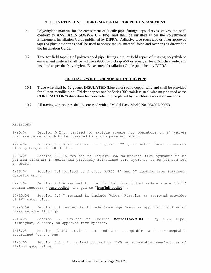
REVISIONS: 4/26/04 Section 5.2.1. revised to exclude square nut operators on 2” valves that are large enough to be operated by a 2” square nut wrench. 4/26/04 Section 5.3.4.2. revised to require 12” gate valves have a maximum closing torque of 180 ft-lbs. 4/26/04 Section 8.1.16 revised to require CAW maintained fire hydrants to be painted aluminum in color and privately maintained fire hydrants to be painted red in color. 4/26/04 Section 4.1 revised to include HARCO 2” and 3” ductile iron fittings, domestic only. 5/27/04 Section 4.1.6 revised to clarify that long-bodied reducers are “full” bodied reducers (“long-bodied” changed to “long/full-bodied”). 10/25/04 Section 3.5.7 revised to include Vulcan Plastics as approved provider of PVC water pipe. 10/25/04 Section 3.4 revised to include Cambridge Brass as approved provider of brass service fittings. 7/18/05 Section 8.3 revised to include Metroflow/M-03 – by U.S. Pipe, Birmingham, Alabama, as approved fire hydrant. 7/18/05 Section 3.3.3 revised to indicate acceptable and un-acceptable restrained joint types. 11/3/05 Section 5.3.4.2. revised to include CLOW as acceptable manufacturer of 12-inch gate valves.
Material Specification - Page 21 of 22
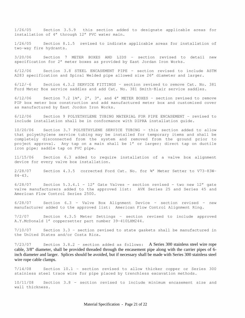
1/26/05 Section 3.5.9 this section added to designate applicable areas for installation of 4” through 12” PVC water main. 1/26/05 Section 8.1.5 revised to indicate applicable areas for installation of two-way fire hydrants. 3/20/06 Section 7 METER BOXES AND LIDS – section revised to detail new specification for 2” meter boxes as provided by East Jordan Iron Works. 6/12/06 Section 3.8 STEEL ENCASEMENT PIPE – section revised to include ASTM A283 specification and Spiral Welded pipe allowed size 26” diameter and larger. 6/12/-6 Section 4.3.2 SERVICE FITTINGS – section revised to remove Cat. No. 381 Ford Meter Box service saddles and add Cat. No. 381 Smith-Blair service saddles. 6/12/06 Section 7.2 1½”, 2”, 3”, and 4” METER BOXES – section revised to remove PIP box meter box construction and add manufactured meter box and customized cover as manufactured by East Jordon Iron Works. 6/12/06 Section 9 POLYETHYLENE TUBING MATERIAL FOR PIPE ENCASEMENT – revised to include installation shall be in conformance with DIPRA installation guide. 10/20/06 Section 3.7 POLYETHYLENE SERVICE TUBING – this section added to allow that polyethylene service tubing may be installed for temporary items and shall be completely disconnected from the system and removed from the ground prior to project approval. Any tap on a main shall be 1” or larger; direct tap on ductile iron pipe; saddle tap on PVC pipe. 11/15/06 Section 6.3 added to require installation of a valve box alignment device for every valve box installation. 2/28/07 Section 4.3.5 corrected Ford Cat. No. for ¾” Meter Setter to V73-83W-84-43. 6/28/07 Section 5.3.4.1 – 12” Gate Valves - section revised - two new 12” gate valve manufacturers added to the approved list: AVK Series 25 and Series 45 and American Flow Control Series 2500. 6/28/07 Section 6.3 – Valve Box Alignment Device - section revised – new manufacturer added to the approved list: American Flow Control Alignment Ring. 7/2/07 Section 4.3.5 Meter Settings – section revised to include approved A.Y.McDonald 1” coppersetter part number 39-410LXM244. 7/10/07 Section 3.3 – section revised to state gaskets shall be manufactured in the United States and/or Costa Rica. 7/23/07 Section 3.8.2 – section added as follows: A Series 300 stainless steel wire rope cable, 3/8” diameter, shall be provided threaded through the encasement pipe along with the carrier pipes of 6-inch diameter and larger. Splices should be avoided, but if necessary shall be made with Series 300 stainless steel wire rope cable clamps. 7/14/08 Section 10.1 – section revised to allow thicker copper or Series 300 stainless steel trace wire for pipe placed by trenchless excavation methods. 10/11/08 Section 3.8 – section revised to include minimum encasement size and wall thickness.
Material Specification - Page 22 of 22
03/26/09 Section 4.3.5 – section revised to include 2” Mueller Co. meter setter. 06/11/09 Section 3.5.7.1 – section revised to include CertainTeed Certa-Lok Yelomine as acceptable PVC pipe. 03/16/10 Section 4.1.1 – section revised to include Uni-Flange Series 1400 as manufactured by Ford Meter Box. 03/16/10 Section 8.3 – Metroflow/M-03 fire hydrant is no longer in manufacture and is removed from the specifications. 03/16/10 Section 10.2 – 3M Gel Pack kit added to specification for tracing wire splicing. 03/22/10 Section 4.3 – section revised to include service fittings manufactured by Cambridge Brass, Inc. 04/12/10 Sections 5.2, 5.3, and 5.4 – sections revised to include AWWA C515 gate valves. 04/11/11 Section 5.4.2 – section revised to include American Flow Control Series 2500 resilient seat gate valve. 04/12/11 Section 4.3.2 – JCM service saddles changed from model 402 to epoxy coated model 406. 04/12/11 Section 4.1.1 – domestic Star Grip added as approved retainer gland. 05/10/11 Revised to require miscellaneous stainless steel to be Series 300. 03/26/12 Section 3.5.7.1 - Northern Pipe Products added as approved PVC pipe supplier. 03/26/12 Section 5.4.2 – section revised to include Clow Corporation large diameter resilient seat gate valve. 03/26/12 Section 10.1 – section revised to require 12-gauge tracing wire. 03/26/12 Section 7.1.2 – Neenah/Deeter Foundry meter box lids models #1750 and #1751 added as approved equal. 03/26/12 Section 7.2.1. – dimensions corrected on the meter box size. 03/26/12 Section 4.3. – numerous product numbers and manufacturer information corrected, primarily to reflect no lead brass requirements. 05/22/13 Section 7.1.2 – two Vestal Manufacturing model numbers added for 15” and 18” meter lids. 5/29/13 Section 4.3.5 - numerous product numbers added for meter setters located in areas where working pressure exceeds 150 psi. 5/29/13 Section 3.5.10 – specification amended to disallow use of PVC pipe where the working pressure exceeds 125 psi.
- i -
TABLE OF CONTENTS FOR SPECIFICATIONS - CONSTRUCTION
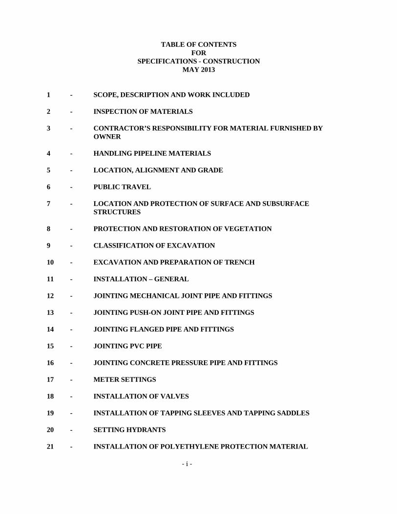
MAY 2013 1 - SCOPE, DESCRIPTION AND WORK INCLUDED 2 - INSPECTION OF MATERIALS 3 - CONTRACTOR’S RESPONSIBILITY FOR MATERIAL FURNISHED BY
OWNER 4 - HANDLING PIPELINE MATERIALS 5 - LOCATION, ALIGNMENT AND GRADE 6 - PUBLIC TRAVEL 7 - LOCATION AND PROTECTION OF SURFACE AND SUBSURFACE
STRUCTURES 8 - PROTECTION AND RESTORATION OF VEGETATION 9 - CLASSIFICATION OF EXCAVATION 10 - EXCAVATION AND PREPARATION OF TRENCH 11 - INSTALLATION – GENERAL 12 - JOINTING MECHANICAL JOINT PIPE AND FITTINGS 13 - JOINTING PUSH-ON JOINT PIPE AND FITTINGS 14 - JOINTING FLANGED PIPE AND FITTINGS 15 - JOINTING PVC PIPE 16 - JOINTING CONCRETE PRESSURE PIPE AND FITTINGS 17 - METER SETTINGS 18 - INSTALLATION OF VALVES 19 - INSTALLATION OF TAPPING SLEEVES AND TAPPING SADDLES 20 - SETTING HYDRANTS 21 - INSTALLATION OF POLYETHYLENE PROTECTION MATERIAL
- ii -
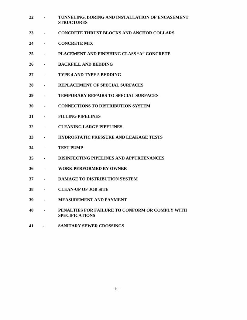
22 - TUNNELING, BORING AND INSTALLATION OF ENCASEMENT STRUCTURES
23 - CONCRETE THRUST BLOCKS AND ANCHOR COLLARS 24 - CONCRETE MIX 25 - PLACEMENT AND FINISHING CLASS “A” CONCRETE 26 - BACKFILL AND BEDDING 27 - TYPE 4 AND TYPE 5 BEDDING 28 - REPLACEMENT OF SPECIAL SURFACES 29 - TEMPORARY REPAIRS TO SPECIAL SURFACES 30 - CONNECTIONS TO DISTRIBUTION SYSTEM 31 - FILLING PIPELINES 32 - CLEANING LARGE PIPELINES 33 - HYDROSTATIC PRESSURE AND LEAKAGE TESTS 34 - TEST PUMP 35 - DISINFECTING PIPELINES AND APPURTENANCES 36 - WORK PERFORMED BY OWNER 37 - DAMAGE TO DISTRIBUTION SYSTEM 38 - CLEAN-UP OF JOB SITE 39 - MEASUREMENT AND PAYMENT 40 - PENALTIES FOR FAILURE TO CONFORM OR COMPLY WITH
SPECIFICATIONS 41 - SANITARY SEWER CROSSINGS

Construction Specification – Page 1 of 60
SPECIFICATIONS - CONSTRUCTION
MAY 2013
1 - SCOPE, DESCRIPTION & WORK INCLUDED
1.1 The protection of the public water supply against contamination or pollution is of the essence of this
Work and is of more importance than any other single feature herein; and the CONTRACTOR shall insure the protection thereof. Any contamination or pollution resulting from acts or omission of the CONTRACTOR shall, in addition to other remedies, be cause for termination of any Contract without notice.
1.2 These general and detailed specifications form a part of the Contract Documents and shall govern
the handling and installation of the pipe and appurtenances. These general and detailed specifications are subject to revision from one project to another. The CONTRACTOR shall make himself familiar with the current revision. These general and detailed specifications, MATERIAL and CONSTRUCTION, may be modified by the SPECIAL CONDITIONS contained within the Contract Documents. Within this document, the terms ENGINEER, INSPECTOR, and OWNER shall both be considered to be CENTRAL ARKANSAS WATER.
1.3 The work intended to be performed under this Contract shall include the furnishing and the
installation of pipes, fittings, valves, hydrants and appurtenances, including wet and tapping connections and other structures, all as described on the Bid Form and Plans and to perform all other work incidental thereto. Items of construction work and/or materials not specifically addressed herein, but nonetheless required for a complete, operating, and acceptable installation of the work, shall be considered subsidiary to the principal bid item requiring such work and/or materials, and the cost thereof shall be considered to be included in the bid price for the principal items. All work shall be performed in a professional manner, consistent with good workmanship practices, and shall meet total satisfaction and approval of the ENGINEER. The ENGINEER or his designated representative (INSPECTOR) may not be on the job site every hour that the CONTRACTOR is performing work. During the days the CONTRACTOR is allowed to perform WORK per the Contract Documents, the CONTRACTOR shall start WORK after dawn each day and complete the day’s WORK by dusk each day. If the City in which the WORK is performed has a more restrictive work or noise ordinance, that requirement shall be followed. Some WORK may be required to be performed at night, weekends, or low water usage times as directed by the Contract Documents, Construction Plans, or the ENGINEER. Certain work, including but not limited to placement of reinforcement steel, placement of concrete, valve operation, pressure and leakage tests, cut and plugs, etc., must be inspected and approved by the ENGINEER before start, completion, or backfill. The CONTRACTOR shall coordinate the inspection of this type of work with the ENGINEER. The CONTRACTOR shall notify the ENGINEER sufficiently in advance of backfilling or concealing any WORK or facilities to permit proper observation. If the WORK or facilities are concealed without approval or consent of the ENGINEER, the CONTRACTOR shall uncover for observation and recover such facilities all at his own expense, when so requested by the ENGINEER. Unsatisfactory work or materials shall be removed and replaced at the CONTRACTOR’S expense. Penalties will be assessed against the CONTRACTOR and/or DEVELOPER for failure to conform or comply with the specifications as detailed in Section 40 of this specification.
1.4 The approximate quantities are shown in the Plans and on the Bid Form.
Construction Specification – Page 2 of 60
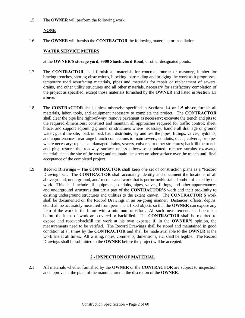
1.5 The OWNER will perform the following work: NONE 1.6 The OWNER will furnish the CONTRACTOR the following materials for installation: WATER SERVICE METERS at the OWNER'S storage yard, 5300 Shackleford Road, or other designated points. 1.7 The CONTRACTOR shall furnish all materials for concrete, mortar or masonry, lumber for
bracing trenches, shoring obstructions, blocking, barricading and bridging the work as it progresses, temporary road resurfacing materials, pipes and materials for repair or replacement of sewers, drains, and other utility structures and all other materials, necessary for satisfactory completion of the project as specified, except those materials furnished by the OWNER and listed in Section 1.5 above.
1.8 The CONTRACTOR shall, unless otherwise specified in Sections 1.4 or 1.5 above, furnish all
materials, labor, tools, and equipment necessary to complete the project. The CONTRACTOR shall clear the pipe line right-of-way; remove pavement as necessary; excavate the trench and pits to the required dimensions; construct and maintain all approaches required for traffic control; sheet, brace, and support adjoining ground or structures where necessary; handle all drainage or ground water; guard the site; load, unload, haul, distribute, lay and test the pipes, fittings, valves, hydrants, and appurtenances; rearrange branch connections to main sewers, conduits, ducts, culverts, or pipes where necessary; replace all damaged drains, sewers, culverts, or other structures; backfill the trench and pits; restore the roadway surface unless otherwise stipulated; remove surplus excavated material; clean the site of the work; and maintain the street or other surface over the trench until final acceptance of the completed project.
1.9 Record Drawings – The CONTRACTOR shall keep one set of construction plans as a “Record
Drawing” set. The CONTRACTOR shall accurately identify and document the locations of all aboveground, underground, and/or concealed work that is performed/installed and/or affected by the work. This shall include all equipment, conduits, pipes, valves, fittings, and other appurtenances and underground structures that are a part of the CONTRACTOR’S work and their proximity to existing underground structures and utilities to the extent known. The CONTRACTOR’S work shall be documented on the Record Drawings in an on-going manner. Distances, offsets, depths, etc. shall be accurately measured from permanent fixed objects so that the OWNER can expose any item of the work in the future with a minimum of effort. All such measurements shall be made before the items of work are covered or backfilled. The CONTRACTOR shall be required to expose and recover/backfill the work at his own expense if, in the OWNER’S opinion, the measurements need to be verified. The Record Drawings shall be stored and maintained in good condition at all times by the CONTRACTOR and shall be made available to the OWNER at the work site at all times. All writing, notes, comments, dimensions, etc. shall be legible. The Record Drawings shall be submitted to the OWNER before the project will be accepted.
2 - INSPECTION OF MATERIAL 2.1 All materials whether furnished by the OWNER or the CONTRACTOR are subject to inspection
and approval at the plant of the manufacturer at the discretion of the OWNER.
Construction Specification – Page 3 of 60
2.2 During the process of loading or unloading, all materials shall be inspected by the CONTRACTOR for damage. Rail shipments unloaded by the CONTRACTOR shall be inspected and any damaged material set aside.
2.3 Inspection of material at the manufacturer's plant, at the point of delivery, on the job site, or in place
shall not relieve the CONTRACTOR of his responsibility and the material may be subject to rejection until final acceptance of the completed project.
2.4 Material contaminated with diesel exhaust or other contaminants will not be accepted.
3 - CONTRACTOR'S RESPONSIBILITY FOR MATERIAL FURNISHED BY OWNER 3.1 The CONTRACTOR'S responsibility for material furnished by the OWNER shall begin at the
point of delivery by the manufacturer, or OWNER, and upon acceptance of the material by the CONTRACTOR.
3.2 All materials removed from the OWNER'S yard or from designated cars or trucks must be shown
out on a ticket furnished by the OWNER. 3.3 Any materials left over shall be returned to the material yard and shown in on a turn-in slip. All
returned pipes shall be straight cut and beveled as specified in Section 13.7. 3.4 Any materials charged out by the CONTRACTOR and not used or not returned will be charged to
the CONTRACTOR. 3.5 Materials may be checked out from the warehouse or returned Monday through Friday, between
8:30 a.m. and 3:30 p.m. 3.6 The CONTRACTOR shall be responsible for the safe storage of all material after delivery to him
by the manufacturer or OWNER and until it has been incorporated in the completed project. 3.7 Any material furnished by the OWNER that becomes damaged after acceptance by the
CONTRACTOR shall be replaced by and at the expense of the CONTRACTOR, and the CONTRACTOR shall promptly remove all such damaged and defective material from the job site.
3.8 All demurrage charges on carloads of materials, which are unloaded by the CONTRACTOR, shall
be paid by the CONTRACTOR. The CONTRACTOR shall also pay any storage charges for unloaded material. When a car is unloaded, the CONTRACTOR shall notify the railroad concerned and make a record of the time and person notified.
3.9 Materials shall be hauled by the CONTRACTOR and the expense of such transportation and
handling shall be included in the bid price.
4 - HANDLING PIPELINE MATERIALS 4.1 The CONTRACTOR shall handle the material with the utmost care and in a manner to prevent
damage to the materials, material coating and lining during loading, hauling, unloading, and installation operations. Material damaged shall be replaced or repaired at the CONTRACTOR'S expense.
4.2 Hooks shall not be in contact with the pipe interior.
Construction Specification – Page 4 of 60
4.3 The interior of the pipeline materials shall be kept free from dirt and foreign matter at all times. Any
pipe or appurtenances contaminated by sanitary sewer and/or hazardous liquid or debris shall be removed from the project area and not used for potable water facility construction; decontamination is not an alternative for use of the pipe or appurtenance for potable water facility construction.
4.4 Pipe line materials, especially valves, hydrants and fittings shall be drained and stored in a manner
to protect them from damage by freezing.
5 - LOCATION, ALIGNMENT AND GRADE 5.1 The CONTRACTOR shall clear a construction right-of-way as narrow as possible and avoid
unnecessary removal or damage to trees, shrubs, and other landscaping. The CONTRACTOR shall remove from the area and properly dispose of all trees, stumps, limbs, piles of excess excavation, rubble, trash, and other debris.
5.2 The pipe, fittings, valves, hydrants, meter settings, and all other appurtenances shall be located and
maintained to conform closely to the location, lines and grades specified or as shown on the Plans. An attempt has been made on the Plans to depict the improvements in their proposed locations, however, the actual location may be different than depicted.
5.3 Valves and hydrants shall be set with operating stem and nut plumb. There shall be no sharp and
sudden breaks, requiring extra fittings and no joint shall be located underneath a sub-structure without the consent of the ENGINEER. The minimum cover over the pipe shall be three feet (3’) and deeper if otherwise indicated on the Plans. When pipeline locations parallel a street, road, or highway and where the top of ground elevation is higher than the road surface, the minimum cover over the water pipe shall be as required to place the top of the water pipe two (2) feet below the elevation of the parallel road ditch flow line. The minimum cover over the pipe laid under ditch and creek crossings shall be four feet (4’) or as otherwise indicated on the Plans. Minimum cover shall be measured from the ground surface or the surface of the permanent improvement to the top of the barrel of the pipe, whichever is greater. Maximum cover shall not exceed six feet (6’) without approval of the OWNER. Cover over the pipe will exceed the minimum requirement of three feet (3’) in the area of air release valves, vacuum valves, and certain other fittings and appurtenances. Extra trench depth required for the proper installation of these fittings and appurtenances will not be paid for separately.
5.4 Horizontal and vertical (where required) control points will be established along or adjacent to the
construction area. It shall be the responsibility of the CONTRACTOR to make necessary measurements from these control points in order to maintain the proper alignment and grade of the structures. The CONTRACTOR shall preserve all stakes and markers established by the ENGINEER. Failure of the CONTRACTOR to preserve such stakes and markers will result in the OWNER'S cost for re-establishment being deducted from amounts due CONTRACTOR.
5.5 In new subdivision construction and along new streets, roads, and highway construction, the
easement and/or right-of-way of the water line shall be graded to within 0.1 foot of finished grade BEFORE installation of any water pipe.
6 - PUBLIC TRAVEL 6.1 The CONTRACTOR shall plan and execute the work so that interference with the flow of traffic
and the passage of pedestrians will be the minimum possible.
Construction Specification – Page 5 of 60
6.2 The CONTRACTOR shall be responsible for making provisions for the safe and free passage of
persons and vehicles by, over, or around the work while it is in progress. Such provisions shall be satisfactory with the ENGINEER and State, County and local authority having jurisdiction within the area of work.
6.3 The CONTRACTOR shall notify applicable State, County or local authority before closing or
obstructing any public highway, street, or road. 6.4. When street cuts are required: 6.4.1 Arkansas State Highway Department - When state highways are to be cut, crossed,
blocked, obstructed, and/or when an excavation in or under a highway right-of-way is required, the OWNER shall obtain a permit for the work at each specific location. The CONTRACTOR shall keep a copy of the permit(s) onsite at all times during work hours.
6.4.2 City of Little Rock - When City of Little Rock streets are to be cut, crossed, blocked,
and/or obstructed, the CONTRACTOR shall prepare a barricade plan(s) and a street cut permit plan(s) for the work. Each separate excavation must be a separate permit request. The CONTRACTOR shall submit the plan(s) to the City of Little Rock Traffic Engineering Specialist (501-340-4854) at the City of Little Rock Traffic Control Office located at 7th Street and Broadway and obtain approval of the barricade plan(s) and street cut permit plan(s), and obtain “B” (barricade) number(s) for the work to be performed. The CONTRACTOR shall keep a copy of the permit(s) and "B" number approval(s) onsite at all times during work hours. The CONTRACTOR must provide the permit number to the OWNER’S Inspector before beginning excavation at a particular location.
6.4.2.1 For street cut permits within the City of Little Rock, the CONTRACTOR is
responsible for payment for the permit(s). The OWNER will not reimburse the CONTRACTOR for the cost of street cut permits or barricade plan approvals obtained from the City of Little Rock.
6.4.3 City of North Little Rock - When City of North Little Rock streets are to be cut, crossed,
blocked, and/or obstructed, the CONTRACTOR shall prepare a barricade plan(s) for the work. The CONTRACTOR shall submit the plan(s) to the City of North Little Rock Traffic Division and obtain approval of the barricade plan(s). It will then be necessary for the CONTRACTOR to obtain a street cut permit(s) for the work from the City of North Little Rock Department of Community Planning. The CONTRACTOR shall keep a copy of permit(s) onsite at all times during work hours. The CONTRACTOR must provide the permit number to the OWNER’S Inspector before beginning excavation at a particular location.
6.4.3.1 For street cut permits within the City of North Little Rock, the CONTRACTOR is
responsible for payment for the permit(s). The OWNER will not reimburse the CONTRACTOR for the cost of street cut permits or barricade plan approvals obtained from the City of North Little Rock.
6.4.3.2 The OWNER will provide signs (without any additional hardware) to the CONTRACTOR as needed to satisfy the North Little Rock city ordinance requiring the posting of signs at all street cut locations. The CONTRACTOR will be responsible for locating and placing the signs as required by the City. Signs provided by the OWNER to the CONTRACTOR shall be returned to the OWNER upon completion of the WORK. No additional or separate payment will be made to the CONTRACTOR for placement, relocation, and/or handling of the
Construction Specification – Page 6 of 60
signs. HOWEVER, if the CONTRACTOR is under contract with a developer and not under contract with Central Arkansas Water, CAW will not provide any signs.
6.4.3.3 The City of North Little Rock requires signs to be placed around a job site informing the general public as to who is performing work. Central Arkansas Water will provide the necessary signs. The CONTRACTOR shall place and maintain the signs until the completion of the WORK. Upon completion of the WORK, the CONTRACTOR shall remove the signs and return them to the ENGINEER. HOWEVER, if the CONTRACTOR is under contract with a developer and not under contract with Central Arkansas Water, CAW will not provide any signs
6.4.4 City of Sherwood - When City of Sherwood streets are to be cut, crossed, blocked and/or
obstructed, the CONTRACTOR shall prepare permit request(s) with traffic control plan(s) for the work. The CONTRACTOR shall submit the plan(s) to the City of Sherwood Engineering Department and obtain approved permit(s) for the work. The CONTRACTOR shall keep a copy of permit(s) onsite at all times during work hours. The CONTRACTOR must provide the permit number to the OWNER’S Inspector before beginning excavation at a particular location.
6.4.4.1 For street cut permits within the City of Sherwood, the CONTRACTOR is
responsible for payment for the permit(s). The OWNER will not reimburse the CONTRACTOR for the cost of street cut permits obtained from the City of Sherwood.
6.4.5 Pulaski County - When Pulaski County roads are to be cut, crossed, blocked, obstructed,
and/or any excavation in or under a county road right-of-way is required, the CONTRACTOR shall prepare permit request(s) with traffic control plan(s) for the work. The CONTRACTOR shall submit the request(s) and plan(s) to the County at 3200 Brown Street, Little Rock, and obtain approved permit(s) for the work. The CONTRACTOR shall keep a copy of permit(s) onsite at all times during work hours. The CONTRACTOR must provide the permit number to the OWNER’S Inspector before beginning excavation at a particular location.
6.4.5.1 For street cut permits within the Pulaski County jurisdiction, the CONTRACTOR
is responsible for payment for the permit(s). The OWNER will not reimburse the CONTRACTOR for the cost of street cut permits obtained from Pulaski County.
6.4.6 Cammack Village - When Cammack Village streets are to be cut, crossed, blocked and/or
obstructed, the CONTRACTOR shall appear at the Cammack Village City Hall to apply for and sign permit(s). Drawing(s) of the proposed work are not required. Address location(s) of the proposed work are required. The CONTRACTOR shall keep a copy of permit(s) onsite at all times during work hours. The CONTRACTOR must provide the permit number to the OWNER’S Inspector before beginning excavation at a particular location.
6.4.6.1 For street cut permits within Cammack Village, the CONTRACTOR is
responsible for payment for the permit(s). The OWNER will not reimburse the CONTRACTOR for the cost of street cut permits obtained from Cammack Village.
Construction Specification – Page 7 of 60
6.4.7 City of Alexander - When City of Alexander streets are to be cut, crossed, blocked and/or obstructed, the CONTRACTOR is not required to obtain a permit from the City of Alexander.
6.4.8 City of Wrightsville - When City of Wrightsville streets are to be cut, crossed, blocked
and/or obstructed, the CONTRACTOR shall prepare permit request(s) with traffic control plan(s) for the work. The CONTRACTOR shall submit the request(s) and plan(s) to Pulaski County at 3200 Brown Street, Little Rock, and obtain approved permit(s) for the work. The CONTRACTOR shall keep a copy of permit(s) onsite at all times during work hours. The CONTRACTOR must provide the permit number to the OWNER’S Inspector before beginning excavation at a particular location.
6.4.8.1 For street cut permits within City of Wrightsville, the CONTRACTOR is
responsible for payment for the permit(s). The OWNER will not reimburse the CONTRACTOR for the cost of street cut permits obtained from the City of Wrightsville.
6.4.9 All street and road repairs shall be performed by the CONTRACTOR in accordance with
the Standard Details. 6.5 When required by the State, County or local authority having jurisdiction thereof, that traffic be
maintained over any construction work in a public highway, street or road, and such traffic cannot be maintained on the alignment of the original roadbed or pavement, the CONTRACTOR shall, at his own expense, construct and maintain a detour around the work. Such detours shall be satisfactory with the ENGINEER and State, County or local authority.
6.6 The CONTRACTOR shall provide and maintain necessary barricades, signs, torches, lights, and
markers around the work in order to protect persons from injury and avoid property damage. The CONTRACTOR shall also provide qualified flagmen to direct traffic while working upon a highway, street, or road over which traffic must pass.
6.7 Excavated areas within the traffic lanes of highways, streets or roads and pedestrian walkways shall
be backfilled as soon as possible and the area opened to traffic. When heavy steel road plates are used in lieu of immediate backfill or used to cover and protect fresh concrete or flowable fill, all edges of the road plates shall be filleted and ramped with cold mix asphalt. The purpose of the asphalt shall be to both hold the plate in place and provide a smooth transition for vehicular traffic.
6.8 The CONTRACTOR shall make the same provisions as described in Section 6.2 herein for the
passage of vehicular and pedestrian traffic between private property and public highways, streets and roads or other provisions that are satisfactory to the ENGINEER and the property owners involved.
6.9 DUST CONTROL & CLEANING OF STREETS - The CONTRACTOR shall take steps to
eliminate dust and mud along streets during the construction period. If, in the opinion of the ENGINEER, dust or mud is excessive, the CONTRACTOR shall immediately take action to resolve the problem. Dust, mud, dirt, and other debris tracked onto paved streets shall be removed daily. The OWNER will furnish unmetered water (where available) necessary for the control of dust and mud. Backflow Preventers shall be furnished and installed by the OWNER between the water source and the hose to be used for washing. Removal or relocation of the Backflow Preventers is prohibited except by and in the presence of the ENGINEER. The CONTRACTOR shall remove all dirt and debris from paved areas by WASHING DAILY. The CONTRACTOR shall be responsible for and shall remedy any blockages of storm drains caused by dirt, mud, or other debris washed from his job site.
Construction Specification – Page 8 of 60
7 - LOCATION & PROTECTION OF SURFACE & SUBSURFACE STRUCTURES 7.1 The approximate locations of subsurface structures known to the OWNER are shown on the Plans.
This information is shown for the guidance of the CONTRACTOR and the OWNER does not guarantee the accuracy or correctness of the locations of such structures as shown. Furthermore, there may be structures that are not shown. It shall be the responsibility of the CONTRACTOR to satisfy himself as to the actual location and nature of subsurface structures. The CONTRACTOR shall comply with the Arkansas One-Call provisions. No excavations shall be made prior to calling Arkansas One-Call and giving proper notification. Not all utility companies are members of the Arkansas One-Call system. Therefore, the CONTRACTOR is advised to contact all non-member utilities and arrange to have their utilities located on within the project area. The CONTRACTOR shall maintain all utility markings until they are no longer needed.
7.2 The CONTRACTOR shall make necessary exploratory excavations to determine the location of
underground structures such as pipes, drains, conduits, and other structures. He shall be responsible for contacting the owners of such structures before excavating in the vicinity of these facilities and shall be guided by their instructions.
7.3 The CONTRACTOR shall provide adequate protection and support for all surface and subsurface
structures or other facilities encountered during the progress of the work. Whenever such structures or facilities are in the same location as the proposed pipe line or appurtenances thereto, the CONTRACTOR shall relocate or reconstruct or cause to be relocated or reconstructed, the structure or facility to the satisfaction of the ENGINEER and utility facility owner. Whenever requested by the ENGINEER or utility owner, the CONTRACTOR shall provide drawings and other plans for supporting or otherwise safeguarding surface and subsurface structures or other facilities which, in the opinion of the ENGINEER, or utility or facility owner, may be damaged as a result of the CONTRACTOR'S work.
7.4 The CONTRACTOR shall not stop or impede the flow in any pipe, sewer, surface drain, or
subsurface drain without making provisions for diverting the flow to the satisfaction of the ENGINEER.
7.5 If any utility facility or structure is damaged during the progress of the work, the CONTRACTOR
shall immediately notify the appropriate owner. Repairs shall not be made by the CONTRACTOR without the prior approval of the utility facility or structure owner. All repairs to sewer facilities or the construction of sewer facilities shall conform to the latest standards of the Wastewater Utility having jurisdiction. The CONTRACTOR shall pay utility owners for the cost of repairing, relocating or replacing any facilities damaged by the CONTRACTOR. In addition, the CONTRACTOR shall provide all assistance available to the utility involved in making repairs under emergency conditions.
7.6 The CONTRACTOR shall not operate a valve in the existing distribution system without the
approval of the ENGINEER. 7.7 All existing fire hydrants and bends shall be blocked or tied in such manner so as to prevent
displacement before excavating behind these appurtenances.
Construction Specification – Page 9 of 60
8 – PROTECTION AND RESTORATION OF VEGETATION 8.1 The CONTRACTOR shall not remove or disturb any vegetation except that required for the
execution of the work. 8.2 Unless otherwise specified in these specifications, in the Plans, or directed by the ENGINEER the
CONTRACTOR shall replace all sod, grass, shrubs, bushes, trees, and flowers, and landscaped areas disturbed or removed, that are located upon public and private property. Trees removed for timber clearing and grubbing of easements shall not be replaced. All debris from clearing and grubbing shall be removed from the job site and properly disposed. The CONTRACTOR shall replant vegetation and re-landscape or cause such to be performed throughout the work area as soon as possible after the pipe lines and appurtenances have been installed. All vegetation damaged during or after removal shall be replaced with healthy vegetation of the same kind or type. All plants shall be replanted in the original location. The CONTRACTOR shall maintain all such replanted vegetation by the application of water, fertilizers, and topsoil. The vegetation shall be cultivated to prohibit the growth of foreign vegetation until a well-developed root system has been established and transplanted vegetation has overcome the "shock" resulting from transplanting. All vegetation that dies or becomes unhealthy shall be replaced by the CONTRACTOR. The contour of the ground shall be left as near the original contour as possible as determined by the ENGINEER.
8.3 In undeveloped areas that have not been landscaped, it is not necessary to replace trees and shrubs
unless otherwise specified in these specifications, in the Plans, or directed by the ENGINEER (seeding of the disturbed area is still required). the CONTRACTOR shall dispose of the vegetation removed to the satisfaction of the ENGINEER.
8.4 The CONTRACTOR shall stabilize all areas where ground surface has been disturbed and erosion
is likely to occur. The method of stabilization shall be approved by the ENGINEER. 8.5 The CONTRACTOR'S attention is called to the fact that not all trees, shrubs, and vegetation are
shown on the Plans. All trees within eight feet (8’) of all water main trenches shall be shall be removed unless otherwise shown on the Plans or directed by the ENGINEER. All stumps shall be removed. Stump holes shall be backfilled to three (3”) to six (6”) inches below finished grade with suitable material from trench excavation, then finished to grade with suitable top soil. In certain areas, the ENGINEER may direct the CONTRACTOR to avoid damaging or removing any trees EXCEPT for those that are required to construct the water facilities.
8.6 In developed areas, vegetation shall be established in all disturbed areas by either seeding or sodding
as directed by the ENGINEER. 8.6.1 Thickness of topsoil shall be three (3”) to six (6") inches. 8.6.2 The CONTRACTOR shall provide high quality sandy loam topsoil with no rocks or
noxious weeds. The topsoil shall be approved by the ENGINEER prior to application. 8.6.3 The CONTRACTOR shall prepare a loose surface seed bed in the area of replacement, to
ensure a minimum depth of two inches (2”). 8.6.4 Areas to be seeded and mulched shall be accomplished by seeding with permanent lawn
grass(es), do not use or place fescue or wheat. Seed shall be placed on a loose surface seedbed. Fertilizer (equivalent analysis 10-20-10) shall be applied to these areas at the rate of 250 lbs. per acre. Seeding and mulch shall be performed in conformance with Section 620 of the Standard Specifications for Highway Construction, Arkansas State
Construction Specification – Page 10 of 60
Highway and Transportation Department, current edition, as modified by this Section 8. Grass mixture shall be as approved by the ENGINEER. Do not use FESCUE or WHEAT seed. SEEDING AND MULCH SHALL BE OF THE HYDRO-SEEDING METHOD/OPTION. Mulch shall be finely chopped. Mulch shall be applied at the rate of 3000 lbs. per acre. Emulsified asphalt shall be applied to mulch at the rate of 0.05 gallons per square yard on all slope areas that are 3:1 or steeper. Payment for seeding and mulch shall be as per Section 39 herein.
8.6.5 Areas designated to be sod do not require fertilizer and straw mulch. New sod shall be of
the same species as the existing turf. Sodding shall be performed in conformance with Section 624 of the Standard Specifications for Highway Construction, Arkansas State Highway and Transportation Department, current edition, as modified by this Section 8. Payment for sodding shall be as per Section 39 herein.
8.7 Ornamental trees and shrubs having a diameter of two inches (2”) or less (measured 6-inches from the
ground) shall be removed and replaced. The CONTRACTOR shall hand dig around the tree or shrub to be replaced. The entire root system shall be removed (minimum 2-foot diameter root ball), wrapped in burlap, moistened and protected.
8.7.1 The CONTRACTOR shall replant/replace any tree or shrub removed within 48-hours of
removal. 8.7.2 A hole shall be excavated sufficient to accommodate the entire root system. The hole shall
be filled with rich topsoil. This material shall be compacted below and around the root system.
8.7.3 Trees or shrubs shall be guaranteed to live for one year after being replanted/replaced. Dead
or dying trees or shrubs shall be replaced within thirty (30) days of written notification at the CONTRACTOR'S expense.
8.7.4 The maximum root size that may be cut on any tree or shrub shall be as set forth in the
following table. Tree trunk Distance Maximum size dia. to face root to be cut 2” – 4” 4.0’ 1”
4” – 12” 6.0’ 3”
12” – 24” 8.0’ 6”
24” + 8.0’ 8”
8.8 In undeveloped areas disturbed during construction, the CONTRACTOR shall place additional
topsoil, if needed, to assure a minimum depth of 2-inches. Vegetation shall be established by seeding and mulch.
8.9 The CONTRACTOR shall thoroughly water all planted and sodded areas and maintain them by
application of additional water and additional fertilizer until an average of 80% of the ground has "established" vegetation.
8.9.1 Restoration of permanent summer lawn grass will be considered complete when the grass has
a well-developed root system showing vigorous runners in all directions and blending with the undisturbed grass adjacent to the area being re-established.
Construction Specification – Page 11 of 60
8.8.1 The OWNER will furnish unmetered water necessary for the establishment of vegetation.
Backflow Preventers shall be furnished and installed by the OWNER between the water source and the hose to be used. Removal or relocation of the Backflow Preventer(s) is prohibited.
8.10 All lawns and maintained grass areas, pastures and meadows, and wooded areas disturbed by
construction shall be restored to a condition equal to or better than that existing prior to construction. In general, all surfaces shall be graded smooth and shall be free of rock, clumps, sticks, or other items. Wooded areas cleared and grubbed of trees shall be only seeded and mulch unless otherwise directed by the ENGINEER.
8.11 Sodding and seeding work shall commence within one month of the installation of a water main
segment. Transplantation of vegetation shall be immediate after installation of pipe. 8.12 Failure to begin vegetation restoration in a timely manner or failure to complete vegetation
restoration to the satisfaction of the property owner and ENGINEER shall result in the ENGINEER securing a licensed landscaping service to perform the work. The cost of the landscaping work will be deducted from monies due the CONTRACTOR.
8.13 The CONTRACTOR shall use suitable equipment for fine grading and landscape work. Heavy
equipment normally associated with utility work is not deemed satisfactory. Equipment of the size and nature normally associated with landscape work shall be used.
8.14 All other work associated with the restoration of vegetation shall be subsidiary to the various pay
items and will not be paid for separately.
9 - CLASSIFICATION OF EXCAVATION 9.1 Rock excavation is defined as all solid rock formations of limestone, sandstone, granite, or similar
rocks in solid beds or masses in original or stratified position which, in the opinion of the ENGINEER, can be removed only by continuous drilling or blasting, or with the use of pneumatic or hydraulic tools, and which, in majority, consistently produces boulders or pieces of detached rocks of at least 1.0 cubic yard in volume. It shall include boulders or pieces of detached rock of at least 1.0 cubic yard in volume and solid rock formations which are interspersed with strata of clay or other material provided that the solid rock constitutes at least seventy-five percent (75%) of the total volume of the particular formation. Folded shale, slate, or other hard rock-like material that can be excavated without, in majority, consistently producing boulders or pieces of detached rock of at least 1.0 cubic yard in volume will not be classified as “rock excavation”. The CONTRACTOR is reminded that blasting, barring, drilling, ramming, hammering, or wedging before an attempt to excavate is made does not necessarily qualify the material to be excavated as "rock excavation" and no payment for "rock excavation" will be made unless the material excavated can conform to the above definition. Rock exterior to the nominal trench width which falls into the excavation will not be measured for payment.
9.2 All other excavation shall be unclassified regardless of the nature of materials encountered. 9.3 If rock excavation is not a bid item on the Bid Form, all excavation shall be considered
unclassified.
Construction Specification – Page 12 of 60
10 - EXCAVATION & PREPARATION OF TRENCH 10.1 Unless bound herein or shown on the Plans, information related to soil conditions obtained by
preliminary soil borings is not furnished by the OWNER. Any information furnished by the OWNER related to soil conditions is not guaranteed to represent actual conditions which the CONTRACTOR will encounter and is to be used at the CONTRACTOR'S risk; therefore, the CONTRACTOR shall take whatever action he feels necessary to satisfy himself as to the actual subsurface soil conditions.
10.2 The trench shall be excavated to the alignment and grade specified and only so far in advance of the
pipe laying as the ENGINEER shall permit. Typical minimum cover over newly laid water main shall be 36-inch unless otherwise directed by the ENGINEER or shown in the Plans. Trenches along public streets or roads shall be limited to 300 feet or less, or as permitted by the governmental authority having jurisdiction. This limit may be reduced by the ENGINEER in congested areas.
10.3 The trench width may vary and depend upon the depth and the nature of the excavated material
encountered. The trench shall be of ample width to permit the pipe to be laid and jointed properly and the backfill to be placed and compacted properly. The minimum width of a trench shall be at least one foot (1’) greater than the nominal diameter of the pipe, except for 2-inch and 3-inch pipe which can be laid in a twelve (12) inch wide trench. Exception to previously stated minimum trench width shall be trenches excavated within paved areas of Pulaski County roads. Pulaski County Road Department requires minimum trench width to be pipe diameter plus twenty-four inches (24”), (12” each side of pipe) to facilitate better compaction of crushed stone backfill. Ledge rock, boulders, large stones, and other rock formation shall be removed to provide a clearance of at least six inches (6”) on each side of pipe line and appurtenances up to and including 24-inches in diameter. For pipelines and appurtenances over 24-inches in diameter, nine inch (9”) clearance shall be provided. Trench width will not be a factor in the measurement and payment of special surface repairs. Measurement and payment of special surface repairs is based on nominal diameter of the pipe as detailed in Section 39.3 of this Specification.
10.4 The bottom of the trench shall be prepared so as to provide a uniform and continuous bearing and
support for the pipe on solid undisturbed or compacted soil. 10.5 The trench shall be excavated to at least the depth specified as follows beyond the specified grade
when the following described conditions exist: 10.5.1 Nine inches (9”) when Type 4 or Type 5 Bedding is specified. 10.5.2 Six inches (6”) for pipelines and appurtenances 24-inches in diameter or less and nine
inches (9”) for pipe lines and appurtenances larger than 24-inches in diameter whenever ledge rock, boulders, large stones, or other rock formation exist in the trench bottom.
10.5.3 Where the bottom of the trench at subgrade is found to be unstable or to include ashes,
cinders, refuse, vegetable or other organic material, or large pieces of inorganic material, that, in the judgment of the ENGINEER, should be removed, the CONTRACTOR shall remove all such material to the extent required by the ENGINEER.
10.6 When the excavation is carried below or beyond that specified or required or whenever the
excavation is carried below or beyond that specified due to conditions described in Section 10.5 above, the CONTRACTOR shall backfill the trench to the proper grade, unless permitted by the
Construction Specification – Page 13 of 60
ENGINEER to install the pipe lines and appurtenances at the undercut grade. The backfill shall be accomplished in accordance with that specified for Type 4 or Type 5 Bedding, elsewhere herein.
10.7 The use of trench-digging machinery will be permitted except in places where operations of same
will cause damage to trees, buildings, or other existing structures above or below the ground; in which case hand methods shall be employed.
10.8 Blasting for excavation will be permitted only after the CONTRACTOR secures the approval of
the ENGINEER and only when proper precautions are taken for the protection of persons and property. The hours of blasting will be fixed by the ENGINEER. Any damage caused by blasting shall be repaired by the CONTRACTOR at his expense. The method of transporting, handling, and storage of explosives and blasting procedure shall conform to Federal Regulations, local and state laws and municipal ordinances.
10.9 The CONTRACTOR shall comply with all federal, state and local laws or ordinances with respect
to obtaining permits, the deposit of bonds and all other provisions of such laws and ordinances. 10.10 Whenever necessary to prevent caving, excavation in sand, gravel, sandy soil, or other unstable
material shall be adequately sheeted and braced or otherwise prepared as per the OSHA Standard for Excavation and Trench Safety System, 29 CFR 1926, Subpart P. Where sheeting and bracing is used, the trench width may be increased accordingly. Trench sheeting shall remain in place until the pipe has been laid and jointed. Where slides or cave-ins occur, the CONTRACTOR shall, at his expense, provide proper bedding and support for the pipe.
10.10.1 EXCAVATION AND TRENCH SAFETY - The CONTRACTOR shall comply with all
parts of the current edition of Occupational Safety and Health Administration Standard For Excavation and Trench Safety System, 29 CFR 1926, Subpart P, which is specifically incorporated herein by reference. The CONTRACTOR shall employ a “COMPETENT PERSON” (as defined in 29 CFR 1926, Subpart P) “capable of identifying existing and predictable hazards” and “who has authorization to take prompt corrective measures to eliminate them”. The CONTRACTOR’S “COMPETENT PERSON” shall perform inspections (as required in 29 CFR 1926, Subpart P) and shall be responsible for determining when Excavation or Trenching Safety Protective Systems are required and how they are to be performed. When so directed by the ENGINEER, the “COMPETENT PERSON” shall provide, to the ENGINEER, documentation, including: date, specific location, condition and depth of trench, specific reasons for protective system and detailed description of the type of protective system employed and design specifications as required in 29 CFR 1926, Subpart P. The CONTRACTOR shall present the name(s) of its COMPETENT PERSON to the ENGINEER prior to beginning work, and any changes in the above personnel shall be reported to the ENGINEER. The OWNER’S or ENGINEER’S inspection of the CONTRACTOR’S WORK shall not be construed to mean, or constitute, acceptance or correctness of the CONTRACTOR’S safety efforts.
10.11 All excavated material shall be piled in a manner that will not endanger the work and that will avoid
obstructing sidewalks and driveways. Gutters shall be kept clear or other satisfactory provisions shall be made for street drainage. If local conditions permit their re-use, all surface materials suitable for re-use in restoring the surface shall be kept separate from the general excavation material. Excess material and debris shall be removed promptly.
10.12 The CONTRACTOR shall remove the minimum amount of street, driveway, sidewalk, parking lot,
or other pavement required to permit installation of the pipelines or appurtenances. The payable width on special surface repair may not be as wide as the width removed for the work. See Section 39 herein for payable width of special surfaces. All pavement surfaces shall be scored in straight lines with suitable equipment before removal. Concrete surfaces shall be scored with a suitable
Construction Specification – Page 14 of 60
concrete saw unless all material is removed between existing construction joints. Asphalt and concrete surface edges shall be saw cut for final repair.
10.13 No excess material shall be disposed in any protected area or in any controlled floodway / floodplain
area. The CONTRACTOR is responsible for locating and securing disposal areas.
11 - INSTALLATION - GENERAL 11.1 All ductile iron pipes, fittings, taps, sleeves, valves, etc. shall be encased in polyethylene
(polywrapped) upon installation (see Section 21 herein for specifics). 11.2 All ductile iron mains shall end with a full joint of mechanical joint pipe with a mechanical joint
plug and anchor collar. 11.3 All PVC main shall be bedded in sand, ASTM C 144, or Class 7 or Class 8 crushed stone, AHTD
specification. Bedding shall be a minimum of four inches (4") below and three inches (3") above the pipe in non-hard rock trench conditions. In hard rock trench conditions, place a minimum of six to nine inches (6” – 9”) below the pipe. PVC pipe shall not be placed in areas with working pressures exceeding 125 psi.
11.4 Before installation of pipe and appurtenances, the trench bottom shall be graded so that uniform
support of the pipe and appurtenances is provided. Shallow depressions shall be made in the trench bottom to accommodate bell ends.
11.5 Proper implements, tools, and facilities shall be provided and used by the CONTRACTOR for the
safe and convenient execution of the work. Under no circumstances shall pipe or accessories be dropped or dumped into the trench.
11.6 All foreign matter or dirt shall be removed from the inside of the pipe and appurtenances before
lowering into the trench and the pipe interior shall be kept clean during and after laying. At all times when pipe laying is not actively progressing (i.e. extended delays during the work day, overnight cessation, weather delays, difficult trenching conditions, etc.), the open ends of the pipe shall be closed and made watertight by installing a plug or cap of sufficient design to prevent trench water, mud, foreign matter, and dirt from entering the pipe line. Plastic sheeting, wood sheeting, tape, steel plate, etc. shall not be used to attempt plugging or capping of the pipe. Plugs and caps shall be true fittings of ductile iron or PVC construction, with gaskets, and they shall be securely fastened to or inserted into the pipe. In less than ideal laying conditions, the ENGINEER may require that a super-chlorinated swab be kept in a pipeline as long as the pipe is being laid. The swab shall be hand pulled through each joint of pipe laid. Care shall be taken to prevent dirt from entering the joint space. ANY PIPELINE, REGARDLESS OF SIZE, FOUND NOT PROPERLY PLUGGED OR CAPPED AT ANY TIME DURING THE INSTALLATION PROCESS SHALL BE PIGGED ITS FULL DIAMETER AND LENGTH AND SHALL BE PIGGED AS MANY MULTIPLE TIMES AS NECESSARY TO SHOW THAT IT IS ABSOLUTELY CLEAN AND CLEAR OF DEBRIS. THE FINAL PIGGING MUST BE WITNESSED BY THE CAW ENGINEER OR HIS REPRESENTATIVE BEFORE CONSIDERED ACCEPTABLE. Any costs associated with the pigging of any line shall be the CONTRACTOR’S responsibility. Refer to Section 32 for pigging requirements.
11.7 Cutting of the pipe for inserting valves, fittings or closure pieces shall be done in a neat and
workmanlike manner without damage to the pipe or pipe lining. Torch cutting is not permitted. All pipes shall be cut at an angle of 90° to the pipe centerline. Cutting at other angles to provide greater deflections at the joints shall not be permitted. Field welding or welding except by the pipe
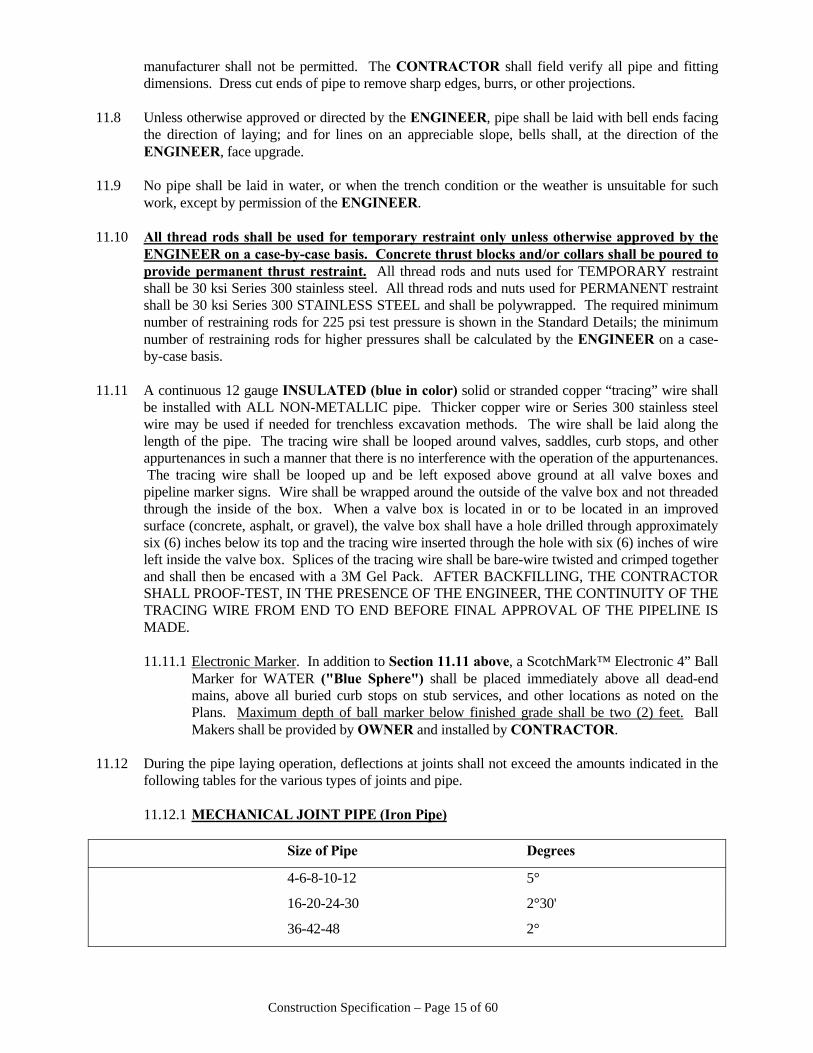
Construction Specification – Page 15 of 60
manufacturer shall not be permitted. The CONTRACTOR shall field verify all pipe and fitting dimensions. Dress cut ends of pipe to remove sharp edges, burrs, or other projections.
11.8 Unless otherwise approved or directed by the ENGINEER, pipe shall be laid with bell ends facing
the direction of laying; and for lines on an appreciable slope, bells shall, at the direction of the ENGINEER, face upgrade.
11.9 No pipe shall be laid in water, or when the trench condition or the weather is unsuitable for such
work, except by permission of the ENGINEER. 11.10 All thread rods shall be used for temporary restraint only unless otherwise approved by the
ENGINEER on a case-by-case basis. Concrete thrust blocks and/or collars shall be poured to provide permanent thrust restraint. All thread rods and nuts used for TEMPORARY restraint shall be 30 ksi Series 300 stainless steel. All thread rods and nuts used for PERMANENT restraint shall be 30 ksi Series 300 STAINLESS STEEL and shall be polywrapped. The required minimum number of restraining rods for 225 psi test pressure is shown in the Standard Details; the minimum number of restraining rods for higher pressures shall be calculated by the ENGINEER on a case-by-case basis.
11.11 A continuous 12 gauge INSULATED (blue in color) solid or stranded copper “tracing” wire shall
be installed with ALL NON-METALLIC pipe. Thicker copper wire or Series 300 stainless steel wire may be used if needed for trenchless excavation methods. The wire shall be laid along the length of the pipe. The tracing wire shall be looped around valves, saddles, curb stops, and other appurtenances in such a manner that there is no interference with the operation of the appurtenances. The tracing wire shall be looped up and be left exposed above ground at all valve boxes and pipeline marker signs. Wire shall be wrapped around the outside of the valve box and not threaded through the inside of the box. When a valve box is located in or to be located in an improved surface (concrete, asphalt, or gravel), the valve box shall have a hole drilled through approximately six (6) inches below its top and the tracing wire inserted through the hole with six (6) inches of wire left inside the valve box. Splices of the tracing wire shall be bare-wire twisted and crimped together and shall then be encased with a 3M Gel Pack. AFTER BACKFILLING, THE CONTRACTOR SHALL PROOF-TEST, IN THE PRESENCE OF THE ENGINEER, THE CONTINUITY OF THE TRACING WIRE FROM END TO END BEFORE FINAL APPROVAL OF THE PIPELINE IS MADE.
11.11.1 Electronic Marker. In addition to Section 11.11 above, a ScotchMark™ Electronic 4” Ball
Marker for WATER ("Blue Sphere") shall be placed immediately above all dead-end mains, above all buried curb stops on stub services, and other locations as noted on the Plans. Maximum depth of ball marker below finished grade shall be two (2) feet. Ball Makers shall be provided by OWNER and installed by CONTRACTOR.
11.12 During the pipe laying operation, deflections at joints shall not exceed the amounts indicated in the
following tables for the various types of joints and pipe. 11.12.1 MECHANICAL JOINT PIPE (Iron Pipe) Size of Pipe Degrees
4-6-8-10-12 5°
16-20-24-30 2°30'
36-42-48 2°
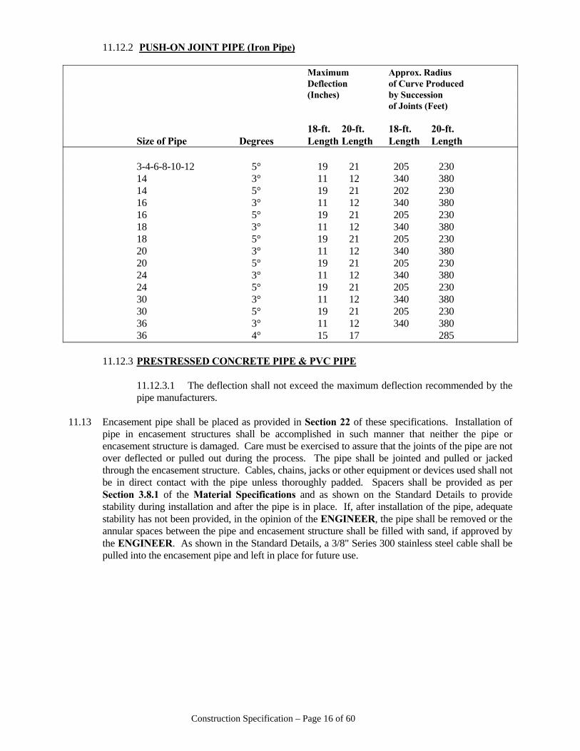
Construction Specification – Page 16 of 60
11.12.2 PUSH-ON JOINT PIPE (Iron Pipe) Maximum Approx. Radius Deflection of Curve Produced (Inches) by Succession of Joints (Feet) 18-ft. 20-ft. 18-ft. 20-ft. Size of Pipe Degrees Length Length Length Length 3-4-6-8-10-12 5° 19 21 205 230 14 3° 11 12 340 380 14 5° 19 21 202 230 16 3° 11 12 340 380 16 5° 19 21 205 230 18 3° 11 12 340 380 18 5° 19 21 205 230 20 3° 11 12 340 380 20 5° 19 21 205 230 24 3° 11 12 340 380 24 5° 19 21 205 230 30 3° 11 12 340 380 30 5° 19 21 205 230 36 3° 11 12 340 380 36 4° 15 17 285 11.12.3 PRESTRESSED CONCRETE PIPE & PVC PIPE 11.12.3.1 The deflection shall not exceed the maximum deflection recommended by the
pipe manufacturers. 11.13 Encasement pipe shall be placed as provided in Section 22 of these specifications. Installation of
pipe in encasement structures shall be accomplished in such manner that neither the pipe or encasement structure is damaged. Care must be exercised to assure that the joints of the pipe are not over deflected or pulled out during the process. The pipe shall be jointed and pulled or jacked through the encasement structure. Cables, chains, jacks or other equipment or devices used shall not be in direct contact with the pipe unless thoroughly padded. Spacers shall be provided as per Section 3.8.1 of the Material Specifications and as shown on the Standard Details to provide stability during installation and after the pipe is in place. If, after installation of the pipe, adequate stability has not been provided, in the opinion of the ENGINEER, the pipe shall be removed or the annular spaces between the pipe and encasement structure shall be filled with sand, if approved by the ENGINEER. As shown in the Standard Details, a 3/8" Series 300 stainless steel cable shall be pulled into the encasement pipe and left in place for future use.
Construction Specification – Page 17 of 60
11.14 Installation of Service Meter Settings – Water service meter settings shall be installed as per the Standard Details. While installing new service corporation taps, prior planning shall be made to ensure that proper alignment between the new corporation stop, new meter setter, and existing customer service line can be accomplished with a minimum of bends in the copper tubing. In instances where bends must occur, all bends shall be made with a manufactured pipe bender of appropriate size to reduce the chances of kinking or flattening of the copper tubing. Hand bending is not allowed. Copper tubing that is kinked or flattened shall be replaced at the contractor’s expense from the corporation stop to the new meter setter. Splicing in sections will not be accepted. Tops of meter boxes shall be flush with the finished grade. All service lines (up to the curb stop located near the meter setter) shall be included in the pressure testing and sterilization work. Installation and connection of meter settings shall commence within one week after successful pressure and bacteriological testing of the water main and be completed within a reasonable period of time. The CONTRACTOR shall have a licensed plumber connect the meter connection “tail piece” to the customer’s private line (house line). All such work and expense shall be included in the Bid Price for meter installations.
11.14.1 The CONTRACTOR’S plumber shall investigate the existing service to determine the
existence of a pressure reducer. If a pressure reducer is located on the existing service line, then the existing pressure reducer shall be connected to the new meter service installation. If more convenient, the CONTRACTOR’S plumber may install a new pressure reducer. All work and materials associated with the reconnection of an existing pressure reducer or installation of a new pressure reducer shall be included in the Bid Price for meter installations. Any damage caused by the failure to reconnection or install a pressure reducer in the service line will be the responsibility of the CONTRACTOR.
11.14.2 “Short side” meter settings are meter settings located on the same side of the
street/road/highway as the water main. For water mains located inside the paved surface of a street/road/highway, the meter setting will be considered “short side” if the water main is on the meter side of the pavement centerline.
11.14.3 “Long side” meter settings are meter settings located on the opposite side of the
street/road/highway from the water main. For water mains located inside the paved surface of a street/road/highway, the meter setting will be considered “long side” if the water main is on the opposite side of the pavement centerline from the meter setting.
11.14.4 For “long side” meter settings, the CONTRACTOR has the option of cutting and replacing
the paved surface (if allowed by the governing street/road/highway department) or boring and pulling the service line under the pavement, unless otherwise directed in the construction plans or Special Conditions of the Contract Documents.
11.14.5 After completion of the meter setting installation, the CONTRACTOR shall remove the
abandoned meter setting (meter, setter, meter box) and repair and/or restore all disturbed areas, including filling the abandoned meter setting with topsoil and placing sod as directed. Sod is typically required around meter installations. Seed and mulch shall be placed only if so directed by the ENGINEER.
11.15 The OWNER shall provide the necessary meters. The meters may be provided new or the meters in
existing meter services may be reused as directed by the ENGINEER. Meters to be reused from existing meter services shall be removed by the CONTRACTOR. The CONTRACTOR shall install the new or reused meters in the new meter settings.
11.16 Water mains crossing sanitary sewer services or mains must clear the sanitary sewer at least eighteen
inches. When a water main crosses under a sanitary sewer main or over a sanitary sewer main with
Construction Specification – Page 18 of 60
less than eighteen inches of clearance, either the sanitary sewer main or the new water main shall be encased in twenty (20) feet of watertight encasement pipe. The ends of the encasement pipe shall be sealed watertight. Encasement spacers are not required for an encasement of this circumstance. When a water main crosses under a sanitary sewer service or over a sanitary sewer service with less than eighteen inches of clearance, the sanitary sewer service pipe shall be removed and replaced with ductile iron pressure pipe as shown in the Standard Details.
11.17 Pipe damaged before installation shall not be used. Pipe damaged or leaking after installation shall
be repaired by cutting out the effected section and be replaced with new pipe. The use of repair clamps, wrap-around repair sleeves, bell joint repair clamps, or other repair fittings will not be allowed.
11.18 In new development construction, other buried utilities such as electrical, gas, TV, and
communication lines shall be no closer than five (5) feet horizontal to the water mains. Buried utilities crossing water mains shall be at right angles thereto. Electrical lines crossing water mains shall be placed in conduit extending five (5) feet each side of the water main.
11.19 Any polyethylene service tubing installed during the work shall be disconnected from the system
and physically removed from the ground prior to final approval of the project. The corporation stop shall be closed water-tight, left in place, and shown (located) on the construction As-Built drawings. A blue marking sphere shall be placed over the abandoned corporation stop prior to final backfill of the excavation.
12 - JOINTING MECHANICAL JOINT PIPE & FITTINGS 12.1 Prior to jointing the pipe and/or fittings, the plain ends of the pipe and the bells of the pipe and
fittings shall be thoroughly cleaned using a soapy water and cloth, removing all foreign materials from the bells, especially the gasket seats.
12.2 The cast or malleable iron follower rings shall be placed on the plain end of the pipe or fittings,
followed by the rubber gasket which has been thoroughly cleansed and lubricated with the soapy water.
12.3 The plain end of the pipe shall be placed in the bell, to which connection is to be made, and
shouldered in back of the bell. The rubber gasket shall be advanced into the bell and seated in the gasket seat; the follower ring shall next be brought into contact with the rubber ring, and all bolts entered and nuts started. The pipe may then be given a maximum deflection as prescribed in the preceding table.
12.4 Joints shall be made tight by advancing the nuts with a wrench 180° apart until a tight joint is made. 12.5 The CONTRACTOR shall provide a torque wrench suitable for measuring tension on bolts for at
least such a time as the workmen making the joints have gotten the "feel" of the required tension. At no time should handles longer than those supplied by the wrench manufacturer be permitted. The torque range shall be as follows:
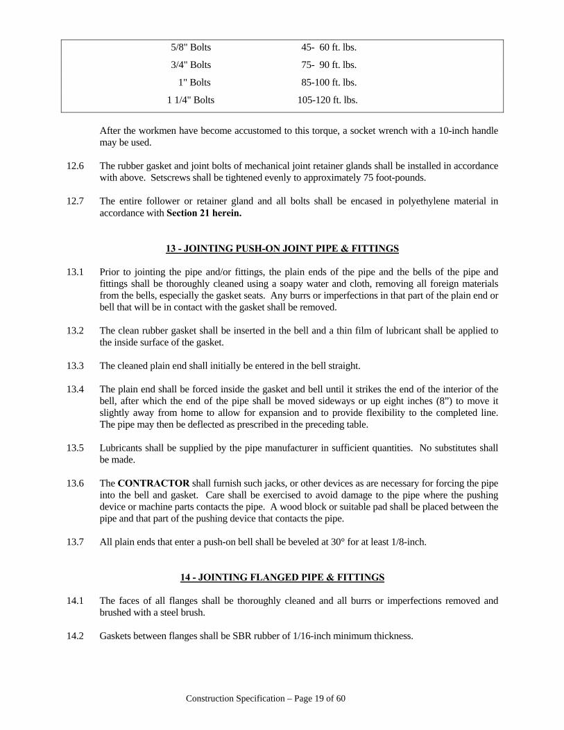
Construction Specification – Page 19 of 60
5/8" Bolts 45- 60 ft. lbs.
3/4" Bolts 75- 90 ft. lbs.
1" Bolts 85-100 ft. lbs.
1 1/4" Bolts 105-120 ft. lbs.
After the workmen have become accustomed to this torque, a socket wrench with a 10-inch handle
may be used. 12.6 The rubber gasket and joint bolts of mechanical joint retainer glands shall be installed in accordance
with above. Setscrews shall be tightened evenly to approximately 75 foot-pounds. 12.7 The entire follower or retainer gland and all bolts shall be encased in polyethylene material in
accordance with Section 21 herein.
13 - JOINTING PUSH-ON JOINT PIPE & FITTINGS 13.1 Prior to jointing the pipe and/or fittings, the plain ends of the pipe and the bells of the pipe and
fittings shall be thoroughly cleaned using a soapy water and cloth, removing all foreign materials from the bells, especially the gasket seats. Any burrs or imperfections in that part of the plain end or bell that will be in contact with the gasket shall be removed.
13.2 The clean rubber gasket shall be inserted in the bell and a thin film of lubricant shall be applied to
the inside surface of the gasket. 13.3 The cleaned plain end shall initially be entered in the bell straight. 13.4 The plain end shall be forced inside the gasket and bell until it strikes the end of the interior of the
bell, after which the end of the pipe shall be moved sideways or up eight inches (8”) to move it slightly away from home to allow for expansion and to provide flexibility to the completed line. The pipe may then be deflected as prescribed in the preceding table.
13.5 Lubricants shall be supplied by the pipe manufacturer in sufficient quantities. No substitutes shall
be made. 13.6 The CONTRACTOR shall furnish such jacks, or other devices as are necessary for forcing the pipe
into the bell and gasket. Care shall be exercised to avoid damage to the pipe where the pushing device or machine parts contacts the pipe. A wood block or suitable pad shall be placed between the pipe and that part of the pushing device that contacts the pipe.
13.7 All plain ends that enter a push-on bell shall be beveled at 30° for at least 1/8-inch.
14 - JOINTING FLANGED PIPE & FITTINGS 14.1 The faces of all flanges shall be thoroughly cleaned and all burrs or imperfections removed and
brushed with a steel brush. 14.2 Gaskets between flanges shall be SBR rubber of 1/16-inch minimum thickness.
Construction Specification – Page 20 of 60
14.3 Care shall be taken to prevent strain of the flanges. All bolts and nuts shall be cleaned and lubricated prior to tightening. Bolts on opposite sides shall be tightened alternately to the torque listed in Section 12.5 herein.
15 - JOINTING PVC PIPE 15.1 Both bell and plain end of pipe shall be thoroughly cleaned before attempting to joint the pipe. 15.2 Lubricate the plain end (do not lubricate the bell end) with approved lubricant and insert plain end
into bell until stop mark on plain end is flush with the end of the bell. In the case of pipe that has two marks on the plain end, insert plain end into bell so that only one mark is visible.
15.3 When the pipe is cut, the plain ends must be beveled similar to the bevel on full lengths. After
beveling, stop marks must be applied to the ends. Use the plain end of another piece of pipe or fitting to determine the location of the stop mark and mark the piece of pipe that has been cut.
15.4 The joints shall be inserted as far as possible on each side of valves that are inserted in the line.
16 - JOINTING CONCRETE PRESSURE PIPE & FITTINGS 16.1 The CONTRACTOR shall furnish to the ENGINEER, for approval, four (4) copies of shop
drawings and laying schedules as prepared by the pipe manufacturer for all pipe, fittings and appurtenances required for the work specified herein. The shop drawings shall depict full details of reinforcement, concrete, and joint dimensions for the pipe, fittings, and appurtenances. The laying schedule shall include, as a minimum, the sequence of installation by piece of material; deflections; station number of each piece and the elevation (flow line or centerline) to which each piece is to be installed; the pressure class of each piece; and the station number for all outlets and appurtenances.
16.2 The pipe shall be installed in accordance with the Plans and the laying schedule furnished by the
pipe manufacturer and as approved by the ENGINEER. The CONTRACTOR is reminded of the fact that the maximum joint deflection of concrete pressure pipe is generally less than other types of pipe and that standard pipe cannot be field cut; therefore, care should be exercised to assure that the pipe is installed to the grade and alignment specified. To assist in preparing the trench bottom on which the pipe is to be installed, the CONTRACTOR shall utilize a laying square of proper design and batter boards or other approved devices or procedures to assure that the proper grade and alignment is achieved. Final grading of the trench bottom shall be accomplished by hand tool methods.
16.3 The bell of the previous piece of pipe installed and the spigot ring of the pipe being installed shall be
well cleaned. All surfaces of the bell shall be free of burrs or other surface defects. 16.4 The spigot end of the length of pipe being installed and the bell end of the previously installed
length of pipe shall be thoroughly lubricated with vegetable soap. The gasket shall be immersed in vegetable soap before it is placed on the spigot of the pipe. The gasket shall be placed in the spigot recess in such manner that it is under uniform tension. Extreme care shall be exercised to assure that the vegetable soap does not become contaminated with dirt, debris, or other contaminants during its use or storage. Contaminated soap shall be discarded.
16.5 Before jointing pipe 20-inches in diameter or smaller, the bell recess of the previously installed
piece of pipe or fitting shall be "buttered" with stiff cement mortar mix described in Section 16.8.1 herein. The quantity of cement mortar placed on the bell recess should be adequate to completely
Construction Specification – Page 21 of 60
fill the interior joint after the pipe is pushed "home". An alternate to the use of cement mortar mix is the use of rope mastic compound placed on the bell recess in lieu of the cement mortar. A quantity of the rope mastic adequate to completely fill the joint recess shall be used. Both the mastic and any priming compound required shall be applied as recommended by the manufacturer; shall be approved by the National Sanitation Foundation for use in potable water vessels and the ENGINEER; shall be flexible after curing; and shall not contain constituents which cause the rubber gasket or any part of the pipe material to deteriorate.
16.6 The CONTRACTOR shall check the gasket of each joint after the joint has been pushed or pulled
partially home to assure proper positioning of the gasket. The feeler gauge furnished by the pipe manufacturer, or a gauge fabricated by the CONTRACTOR to the exact dimensions of that recommended by the pipe manufacturer, shall be used. The piece of pipe being installed shall be carefully lowered into the trench and the spigot end inserted into the bell end of the piece of pipe or fitting previously installed. The following procedure shall apply with respect to checking the joint gaskets:
16.6.1 24-inch Diameter Pipe and Larger. Temporary inserts, 5/8-inch thick, shall be placed
between the tip of the spigot and the seat of the bell on the inside of the pipe to provide space for inserting the feeler gauge. The piece of pipe being installed is then pushed or pulled until the inserts prohibit further insertion. The feeler gauge shall be passed around the entire interior circumference of the joint. If the gasket cannot be "felt" around the entire circumference, the piece of pipe being installed shall be withdrawn and the gasket examined. If the gasket is damaged, it shall be replaced. If undamaged, the gasket shall then be lubricated before re-use. After proper gasket positioning has been achieved, the inserts shall be removed and the piece of pipe being installed shall be pushed or pulled "home".
16.6.2 20-inch Diameter Pipe and Smaller. The piece of pipe being laid shall be pushed or
pulled completely "home", after which the feeler gauge is passed around the entire exterior circumference of the joint. If the gasket cannot be "felt" around the entire circumference, the procedure outlined in Section 16.6.1 above shall apply.
16.7 After each piece of pipe or fitting has been installed, the grade, alignment, and joint opening shall be
checked by the CONTRACTOR. If the proper grade and alignment has not been achieved, the piece of pipe or fitting shall be adjusted to the proper position. "Blocking" pipe up that is too low shall not be permitted. If the pipe is too low, it shall be removed and well-compacted backfill, as specified in Section 10.6 herein shall be placed in the trench bottom to sufficient depth to attain the proper grade. Joints that are to be deflected shall be pushed "home" and then deflected. The joint opening after final positioning shall not exceed that recommended by the pipe manufacturer. Such backfill shall be provided at no additional cost to owner.
16.8 Joint protection shall be applied in accordance with the following procedures, at least two pipe
lengths, except where noted, behind final positioning of the pipe in the trench. 16.8.1 Inside. Mortar for application to the interior of joints shall consist of one (1) part Portland
cement and one and one half (1½) parts clean washed sand and clean water of sufficient quantity to provide a stiff mix.
16.8.1.1 20-inch Diameter Pipe and Smaller. The mortar placed on the bell recess, as
described in Section 16.5 above, shall be smoothed, cleaned and excess mortar removed before the mortar begins to harden using a suitable swab or by pulling an inflated rubber sewer plug through the pipe. The outside diameter of the swab or plug shall be only slightly smaller than the inside diameter of the pipe.
Construction Specification – Page 22 of 60
Alternate methods may be used on approval of the ENGINEER. If rope mastic, described in Section 16.5 above, is used, the interior of the pipe shall be visually inspected. If excess material extends below the interior surface of the pipe, the smoothing procedures described above shall be followed.
16.8.1.2 24-inch Diameter Pipe and Larger. Mortar shall be placed in the inside of the
joint recess and finished smooth from inside the pipe using hand tools. 16.8.2 Outside.
16.8.2.1 All soil and other material shall be removed from the joint recess and from the pipe on each side of the joint. A suitable cloth, reinforced paper or plastic wrapper, at least seven (7) inches in width and of sufficient length to reach around the exterior circumference of the pipe, shall be placed around the pipe, centered on the joint opening, and secured to the pipe with wire or steel strapping on each side of the wrapper. The ends of the wrapper shall meet the top of the pipe in an opening provided for the introduction of cement grout. All wrappers shall be those furnished by the pipe manufacturer.
16.8.2.2 A cement grout mixture consisting of one (1) part Portland cement and two (2)
parts clean washed sand and clean water of sufficient quantity to provide a pourable mix, shall be poured into the opening and vibrated and rodded or puddled until the grout completely fills the recess around the entire circumference of the pipe. Care must be exercised to assure that there is adequate space between the pipe and trench bottom where the wrapper is located to permit the grout to flow around the bottom of the pipe. The wrapper shall be re-positioned or the wire or steel bands tightened if the grout escapes around the wrapper. The opening at the top of the pipe, where the grout was poured, shall be filled with a stiff mortar mix described in Section 16.8.1 above.
16.8.2.3 Grout and cement mortar shall be protected to prohibit freezing during the curing
period. Any joint showing excess shrinkage or cracking after curing shall be cleaned and remade. Backfill shall not be commenced before grout achieves initial set.
16.8.2.4 When installed inside encasement structures where space restrictions prohibit
access to the exterior of the joints after final placement of the pipe, rope mastic compound, described in Section 16.5 above, or a continuous loop of polyurethane foam impregnated with dry Portland cement, equal to FLEX-PROTEX, shall be placed in the joint recess in sufficient quantity to completely fill the recess.
16.8.2.5 All exposed steel parts of pipe and fittings shall be coated with cement mortar,
described in Section 16.8.1 above, or completely encased in concrete. The cement mortar or concrete shall be at least two inches (2”) thick. The cement mortar used around closure pieces and other fittings having large areas of exposed steel shall be reinforced with suitable wire mesh.
17 – METER SETTINGS 17.1 Meter settings shall be installed where shown on the Plans and/or as directed by the OWNER.
Installation shall be as per the Standard Details. Meter settings shall be installed at a location that is
Construction Specification – Page 23 of 60
outside areas of vehicular traffic and still accessible to Central Arkansas Water personnel. Meter setters shall be installed in a horizontal and plumb position within the meter box and at a depth to provide the required space between the top of the meter and the bottom of the meter box lid.
18 - INSTALLATION OF VALVES
18.1 Valves shall be jointed in accordance with the methods of jointing pipe as specified elsewhere
herein. Valve stems shall be plumb and there shall not be any obstructions that will prohibit the installation of valve boxes directly over the stem. Concrete anchor collars shall be provided around an adjoining length of pipe for all valves 16-inches in diameter or larger and for smaller valves when specified on the Plans. Mechanical joint retainer glands shall be installed on all valves with mechanical joint ends 12-inches in diameter or larger when ductile iron pipe is specified and for smaller valves when specified. All valves shall be firmly supported from below with compacted dry soil, compacted crushed stone, or concrete.
18.2 After installation of the valve and before backfilling, an Electronic Water Marker ("Blue Sphere")
shall be placed one foot (1’) north and even with the top of the operator on those valves which are specified in the Plans or as directed by the OWNER. Blue Spheres shall be provided by the OWNER.
18.3 Valve boxes shall be installed over the operating nut of each valve and be of adequate length to
reach the finished ground or paved surface. Valve boxes shall be installed with a HDPE Valve Box Alignment Device of the proper size and manufacture to fit the valve and the valve box. Boxes shall be firmly supported, plumb, and centered over the valve operating nut. No part of the box shall rest on the valve. The box cover shall be flush with the finished surface.
18.3.1 In order to assist in future locating, valve boxes located in undeveloped areas shall have a
2.0’ x 2.0’ x 0.5’ (thick) Class “A” or “B” concrete pad, reinforced with #4 reinforcement steel, constructed around the top of the valve box, flush with the settled/compacted finished grade.
18.4 When the distance between the valve operating nut and the finished surface exceeds five feet (5’), a
valve stem extension shall be provided. The valve stem extension shall be of sufficient length to leave the top of the extension (2-inch square nut) 12 to 24 inches below finished grade. All components of the extension shall be Series 300 stainless steel. The stem shall be round stainless steel bar stock or stainless steel pipe of the dimensions shown below with a 2-inch square bar steel operating nut attached to the upper end. A box wrench, 2 1/8" I.D. square, made from Series 300 stainless steel 3/16-inches thick shall be welded to the lower end of the stem extension which will fit over the valve operating nut. Two-inch valves with a tee-head operating nut will require a rectangular shaped box wrench on the end of the valve stem extension. A round center guide made from 3/16-inch or 1/4-inch steel plate shall be placed on the valve stem extension approximately 6-inches from the upper end. The diameter of the guide shall be slightly less than the inside diameter of the valve box. The guide shall be affixed to the stem extension in such a way that it can rotate freely on the stem. Approximate dimensions for the valve stem extensions for various size valves shall be as follows:
Construction Specification – Page 24 of 60
Stem Size Valve Size (S.S. Steel Pipe) Stem Size Maximum and Type (Sch 40) (S.S. Bar Stock) (Depth of Bury) 2” Gate 3/4” 3/8” 10’
3” – 10” Gate 1” 7/16” 13’
12” – 18” Gate 1 1/4” 7/16” 13’
20” & Larger Gate 1 1/2” 1/2” 21’
12” – 36” Butterfly 1 1/4” 7/16” 13’
42” & Larger Butterfly 1 1/2” 1/2” 21’
Note: *Welds on stem extensions (top and bottom nut) shall be 1/8" - 3/16" fillet weld around full
circumference. 18.4.1 Shop drawings shall be submitted to the ENGINEER for approval prior to installing the
stem extension pieces.
19 - INSTALLATION OF TAPPING SLEEVES & TAPPING SADDLES 19.1 The pipe shall be free of dirt and other debris before attaching tapping sleeve or tapping saddle.
That part of the pipe barrel, other than concrete pipe, which will be in contact with the gasket of tapping saddles, shall be smooth. All rough areas on the pipe barrel shall be smoothed. The CONTRACTOR shall field verify all pipe and fitting dimensions. Tapping sleeve, tapping saddle, or direct tap shall be installed at least twenty-four (24) inches from bell joints, fittings, end of pipe joint, or another tap.
19.2 Tapping saddles or sleeves shall be bolted securely to the pipe. The face of the outlet shall be
plumb. Mechanical joint glands for tapping sleeves shall be installed in accordance with Section 12 herein. The strap bolts for tapping saddles shall be alternately tightened "snug" and then alternately tightened to a torque of 100 foot-pounds.
19.3 The tapping valve shall be bolted securely to the tapping sleeve or tapping saddle outlet flange. The
tapping valve shall be adequately supported from beneath. The weight of the tapping valve shall not be supported by the tapping sleeve/saddle. A concrete “mud slab” at least six (6) inches thick shall be poured under the location of all tapping valves 14 inches and larger and the weight of the valve shall be supported by the mud slab. The tapping machine shall be bolted securely to the valve.
19.4 After installation of the tapping sleeve or saddle and the tapping valve and before drilling through
the pipe, the assembly shall be hydrostatically tested at the pressure specified in Section 33, herein, by introducing water through the sleeve or saddle test tap.
19.5 The pilot drill and shell cutter shall be in good condition. The pilot, shell cutter, and any other
component of the tapping machine that will or may come into contact with the interior of the tap valve, tap saddle, or potable water pipe, shall be thoroughly sterilized with straight bleach or super-chlorinated solution. The shell cutter shall be the size required to cut the full opening specified.
Construction Specification – Page 25 of 60
19.6 Only qualified operators shall operate the tapping machine. The "coupon" shall be withdrawn and be given to the ENGINEER for inspection. Care shall be exercised to avoid drilling or cutting the backside of the pipe by carefully assuring the engagement of the pilot drill and shell cutter shaft.
19.7 Openings in the pipe barrel for tapping saddles installed on dry pipe shall be cut with a pilot drill
and shell cutter. Torch cutting is not permitted. 19.8 Tapping operations must not commence before inspection by the ENGINEER or his authorized
representative. Tapping operations must not commence before the tapping assembly has passed a pressure test as detailed in Section 33.4.1 herein.
19.9 A thick coat of coal tar epoxy or other approved bituminous material shall be applied to the straps
and bolts of saddles after installation and cleaning or by enclosing polyethylene material in accordance with Section 21 herein.
19.10 Tapping saddles and sleeves with a run size 2" or larger shall be adequately thrust blocked with
concrete.
20 - SETTING HYDRANTS 20.1 Hydrants shall be color coded as specified in Section 8.1 of the Material Specifications. Hydrants
shall be painted with a minimum of two coats of paint. Hydrants shall be thoroughly cleaned before setting, removing all dirt and foreign matter from the barrel and bottom section up to the main valve. The main valve shall be in the "closed" position and the waste outlet shall be free of any obstructions.
20.2 Hydrants shall be located a safe distance from driveways, roadways and narrow type sidewalks and
in a manner to provide complete accessibility, and they shall stand plumb with nozzles at proper elevation. The hydrant’s “bury line” shall be set at or no more than four (4) inches above the finished grade elevation; therefore the bottom of hydrant nozzles shall be 18 to 22 inches above the finished grade elevation.
20.3 Unless otherwise directed, the large diameter nozzle shall be no less than twenty-four inches (24")
from back of the curb. 20.4 The CONTRACTOR shall, if necessary, rotate the hydrant barrel or nozzle section at the flanged
joint to obtain the desired nozzle position as specified by the ENGINEER. The pumper nozzle shall be at a right angle to and face the street unless otherwise directed by the ENGINEER.
20.5 The bowl or bottom of the hydrant shall be supported firmly on the bottom and shall be well braced
against unexcavated earth on the backside of the hydrant. Stone slabs, concrete blocks, or other suitable material may be used to block the hydrant. If considered necessary by the ENGINEER, the hydrant shall be tied to the branch pipe with suitable Series 300 STAINLESS STEEL rods or clamps. These rods or clamps shall be furnished by the CONTRACTOR without additional compensation.
20.6 A drainage bed shall be provided under and around the base of the hydrant of at least six (6) cubic
feet in volume and extending at least six inches (6”) above the drain outlet and shall consist of gravel or broken stone mixed with coarse sand and thoroughly compacted. Under no circumstances shall the drain outlet on the hydrant or the drainage bed be connected to a sewer.
20.7 Backfilling and tamping around hydrant barrels shall be continuous in operation.
Construction Specification – Page 26 of 60
20.8 If a fire hydrant is not located inside a concrete paved area, then a 2.0' x 2.0' x 1.0' (deep) Class "A"
concrete pad, reinforced with #5 reinforcement steel shall be poured just below the break-away joint of the fire hydrant barrel.
20.9 Fire hydrants, immediately after installation, shall be covered and wrapped with a heavy cloth,
water-resistant sack, or black polyethylene sheeting, well taped in place around the hydrant, to identify the hydrant as being “not in service”. After the hydrant is tested and placed into service, the identifying cover shall be removed.
21 - INSTALLATION OF POLYETHYLENE PROTECTION MATERIAL 21.1 Polyethylene material, either in tubing form or in the form of flat sheet or rolls, as specified herein,
shall be placed around all buried mechanical joints of pipe and fittings, valves, fire hydrants, and all saddles, sleeves, and couplings, tapping saddles, and any other appurtenance with exposed bolts. Any and all iron or steel components installed below ground shall be wrapped with the polyethylene material.
21.2 Ductile iron and steel pipe and appurtenances shall be completely encased in polyethylene tubing
material. It is not the intent that the material form an enclosure that is absolutely air or water tight, but to prevent pipe to soil contact.
21.3 Polyethylene tubing shall be applied to pipe by one of the following methods: 21.3.1 Method "A": Cut polyethylene tube to a length approximately two feet (2’) longer than the
length of the pipe section. Slip the tube around the pipe, centering it to provide a one foot (1’) overlap on each adjacent pipe section, and bunching it accordion fashion lengthwise until it clears the pipe ends. Lower the pipe into the trench and make up the pipe joint with the preceding section of pipe. A shallow bell hole must be made at joints to facilitate installation of the polyethylene tube. After assembling the pipe joint, take bunched polyethylene from the preceding length of pipe, slip it over the end of the new length of pipe, and secure in place. Then slip the end of the polyethylene from the new pipe section of the end of the first wrap until it overlaps the joint at the end of the preceding length of pipe. Secure the overlap in place. Take up the slack width to make snug, but not tight, fit along the barrel of the pipe, securing the fold at quarter points with tape.
21.3.2 Method "B": Cut polyethylene tube to a length approximately one foot (1’) shorter than the
length of the pipe section. Slip the tube around the pipe, centering it to provide six inches (6”) of bare pipe at each end. Make polyethylene snug, but not tight; secure ends. Before making up a joint, slip a three foot (3’) length of polyethylene tube over the end of the preceding pipe section, bunching it accordion fashion lengthwise. After completing the joint, pull the three foot (3’) length of polyethylene over the joint, overlapping the polyethylene previously installed on each adjacent section of pipe by at least one foot (1’); make snug and secure each end.
21.4 Pipe-Shaped Appurtenances. Bends, reducers, offsets, and other pipe-shaped appurtenances shall be
covered with polyethylene in the same manner as the pipe. 21.5 Odd-Shaped Appurtenances. Valves, tees, crosses and other odd-shaped pieces which cannot
practically be wrapped in a tube, shall be wrapped with a flat sheet or split length of polyethylene tube. The sheet shall be passed under the appurtenance and brought up around the body. Seams shall be made by bringing the edges together, folding over twice, and taping down. Slack width and
Construction Specification – Page 27 of 60
overlaps at joints shall be handled as described in Section 21.3.1 above. Tape polyethylene securely in place at valve stem and other penetrations.
21.6 Openings in Tubing Material. Openings for branches, service taps, blowoffs, air valves, and similar
appurtenances shall be made by making an “X” shaped cut in the polyethylene and temporarily folding the film back. After the appurtenance is installed, tape the slack securely to the appurtenance and repair the cut, as well as any other damaged areas in the polyethylene with tape.
21.7 Junctions Between Wrapped and Unwrapped Pipe. Where polyethylene wrapped pipe joins a pipe
that is not wrapped, extend the polyethylene tube to cover the unwrapped pipe a distance of at least two feet (2’) and secure the end.
21.8 The polyethylene material shall be secured around the pipe and appurtenances by at least three (3)
circumferential wraps of tape (see Section 9 of the Material Specifications). 21.9 All tongs, cables, or chains that are used for lifting pipe and appurtenances that have been encased in
polyethylene material shall be adequately padded to prevent damage to the material. 21.10 Repair any rips, punctures, or other damage to the polyethylene with tape or with a short length of
polyethylene tube cut open, wrapped around the pipe and secured in place. 21.11 Polyethylene material shall be stored on the job site in such a manner that it is not exposed to direct
sunlight. Exposure during installation shall not exceed forty-eight (48) hours. 21.12 Backfill material shall be the same as specified for pipe without polyethylene wrapping. Special
care shall be taken to prevent damage to the polyethylene wrapping when placing backfill. Backfill material shall be free from cinders, refuse, boulders, rocks, stones, and/or other material that could damage polyethylene.
22 - TUNNELING, BORING and INSTALLATION OF ENCASEMENT STRUCTURES 22.1 The CONTRACTOR shall inspect the location where encasement structures are to be installed and
familiarize himself with the conditions under which the work will be performed and with all necessary details as to the orderly prosecution of the work. The omission of any details in the Plans and Specifications for the satisfactory installation of the work in its entirety, which may not appear herein, shall not relieve the CONTRACTOR of full responsibility.
22.2 The CONTRACTOR shall satisfy himself of soil conditions by means he deems necessary, i.e.
exploratory boring or exploratory pit excavations at tunnel ends. All such exploratory work shall be done in such a manner as to not jeopardize highway or railroad fill, and shall be satisfactorily backfilled and cleaned up.
22.3 The size structure as shown on the Plans is considered as the "minimum acceptable size". If the
CONTRACTOR deems that it would be to his advantage to install a larger structure, he may do so subject to the approval of the ENGINEER. If the CONTRACTOR elects to use larger structures, the unit bid price as stated in the Bid for the size structure specified will be considered the unit bid price for the larger structure. In no case will the OWNER be liable for extra payment for structures larger than the size specified.
22.4 Encasement structures shall be installed at the grades and alignment shown on the Plans or directed
by the ENGINEER. Maximum vertical deviation shall not exceed 0.5 foot from the elevations shown on the Plans or directed by the ENGINEER. Maximum horizontal deviation shall not
Construction Specification – Page 28 of 60
exceed 0.5 foot from the alignment shown on the Plans or directed by the ENGINEER. Deviations exceeding the maximums must be pre-planned by the CONTRACTOR and approved in writing by the ENGINEER.
22.5 Where open cut is not practical or permitted, the encasement structure shall be installed by
simultaneous dry auger bore and encasement jacking, unless some other method is approved in writing by Central Arkansas Water. Timber or steel guide rails shall be used. The grade, slope, and alignment of the guide rails shall be carefully set in order to attain the specified grade and alignment.
22.6 Pits and trenches shall be sheeted and braced in accordance with Section 10 herein. 22.7 Damage to the pipe coating during shipment or handling shall be repaired. 22.8 The excavation and backfill of encasement pipe installed in open cuts shall be in accordance with
the provisions contained elsewhere herein for other pipe. 22.9 Smooth wall steel pipe shall be connected by full penetration butt-welding. 22.10 Steel liner plates shall be installed immediately after excavation has proceeded sufficiently to
accommodate another section. All bolts shall be securely tightened. 22.11 The construction of encasement structures by tunneling or boring shall be carried out in such manner
that settlement of the surface above the structure does not occur. The excavation shall be performed so that voids around the structures are held to a minimum. Voids around the periphery of the structures shall be filled by pressure grouting. The grout shall be one (1) part Portland cement and two (2) parts sand with water adequate to permit pumping on encasement structures 24-inches in diameter and larger. The grout shall be introduced through suitable fixtures and placed through the structure wall at intervals adequate to completely fill all voids. The fixtures shall have pressure tight caps that shall be closed after the grouting operations have been completed. The grouting pressure shall be sufficient to completely fill all voids without causing upheaval of overburden above the encasement structure but shall not exceed five (5) psi. If voids exist around structures smaller than 24-inches in diameter, the CONTRACTOR shall introduce grout to completely fill the voids through suitable borings made from the surface.
22.12 For carrier pipe lines 6-inch diameter and greater, a Series 300 stainless steel wire rope cable, 3/8”
diameter, shall be threaded through the encasement along with the carrier pipe, the purpose of the cable is to aid in the removal of the carrier pipe if removal is ever required. The cable ends shall extend ten (10) feet past each end of the encasement pipe and the ten (10) foot cable ends shall be wrapped loosely around the carrier pipe and secured in place before backfilling; wrap around the outside of polyethylene encasement if present. Splices in the cable shall be avoided, but if necessary shall be made with a minimum of three (3) Series 300 stainless steel wire rope cable clamps per splice. After the carrier pipe has been pulled through the encasement pipe, the ends of the encasement pipe shall be sealed with brick and mortar as shown in the Standard Details. A vent at each end of the encasement pipe shall be constructed as shown in the Standard Details unless otherwise deleted by the ENGINEER.
22.13 Moleing and other installation methods may be considered and approved by the ENGINEER for
installation of un-encased main and service pipe.
Construction Specification – Page 29 of 60
23 - CONCRETE THRUST BLOCKS & ANCHOR COLLARS 23.1 Concrete thrust blocks and anchor collars shall be provided along the pipeline in accordance with
the construction details, plan sheets, or as directed by the ENGINEER. The concrete mix (as defined in Section 24 herein) shall be Class "A" for anchor collars and Class "B" for thrust blocks. All bends, tees, caps, plugs, and fire hydrants shall be thrust blocked unless specifically detailed in the construction plans that no thrust blocking is required. Anchor collars shall be constructed on ductile iron (or approved steel) pipe only; if the pipeline being restrained is primarily PVC or other non ductile iron pipe, at least one full joint of ductile iron (or approved steel) pipe shall be inserted in the pipeline run to receive the concrete anchor collar.
23.2 Concrete for thrust blocks and anchor collars shall be placed against undisturbed soil. The
excavation shall be hand shaped and free of loose material. Forms shall be used to confine the concrete in areas other than that part that is in contact with undisturbed soil in the direction of the thrust.
23.3 No concrete shall be placed around any part of a joint or placed so that it interferes with the removal
of any joint accessories such as bolts, followers, threads, collars, couplings, etc. Fire hydrant drains shall not be restricted.
23.4 The top of the concrete thrust block or anchor collar shall be struck off with a wood straight edge or
float. 23.5 Concrete shall not be placed when the temperature is below 40°F and dropping or below 35°F if the
temperature is rising, unless approved by the ENGINEER. Placement shall be in accordance with Sections 25.5.1 through 25.5.4 herein.
23.6 Admixtures are not to be used without the approval of the ENGINEER. 23.7 All reinforcement shall be inspected by the ENGINEER prior to placement of concrete. All
placement of concrete must be in the presence of the ENGINEER or his representative. The CONTRACTOR is cautioned that he may be required to remove, without compensation, any concrete placed in the absence of the ENGINEER or his representative.
23.8 Backfill over concrete thrust blocks or anchor collars shall not be placed before the concrete has
attained initial set. 23.9 No thrust blocks shall be less than six inches (6”) thick between the pipeline or appurtenances and
undisturbed soil in the direction of thrust on pipes 12-inch diameter and smaller. On larger pipes, the thickness of thrust blocks shall be as directed by the ENGINEER. A thrust block with any component of its length to width to depth ratio exceeding two (2) shall be reinforced with steel reinforcement bars as directed by the ENGINEER. The ENGINEER will consider the size of the thrust block, the size of the water main, and the system pressure in the determination of the size and spacing of the steel reinforcement.
23.10 The excavation shall be free of water before concrete is placed. Steel reinforcement, as specified on
the plans, shall be placed in accordance with Section 25.2 herein. 23.11 The pipe or appurtenances to be in direct contact with concrete shall be cleaned before placing the
concrete.
Construction Specification – Page 30 of 60
23.12 The area of contact of the thrust blocks and anchor collars shall be sufficient to resist the thrust. This will vary depending on the safe bearing value of the soil. Suggested safe soil bearing values are as follows:
TYPE OF SOIL SUGGESTED SAFE BEARING VALUES (TONS \ SQ. FT.)
Solid Rock 25.0 TONS / SQ. FT.
Hard Shale 6.0
Medium Shale 4.0
Soft Shale 2.0
Dry Clay Gravel 4.0
Soft Clay 1.125
Dry Sand or Loam 2.0
Wet Clay 0.55
The above values are approximate, will vary considerably, and are intended to be used only as a
guide. The CONTRACTOR is responsible for determining the soil bearing value or taking other action to assure that the bearing area is adequate to restrain the pipe or appurtenances.
23.13 Where the soil is unstable or in the case of recent fill areas, the following procedures shall apply
either singly or in a combination: 23.13.1 Thrust blocks shall be of adequate size to restrain pipe or appurtenances by mass alone
without depending on horizontal bearing of the soil. 23.13.2 The excavation shall extend deep enough to contact firm soil and the thrust block concrete
brought up to the pipe or appurtenances. The thrust block shall be constructed so that the block acts as a beam and will provide the restraint required. Such block shall be reinforced with steel reinforcing bars.
23.13.3 Anchor blocks shall be constructed in a firm soil and tie rods extended to the pipe or
appurtenances. Tie-rods shall be used only for temporary restraint. Concrete thrust blocks and/or anchor collars must be placed for permanent restraint.
23.14 Thrust blocks for vertical bends shall be adequate to resist the thrust by mass alone when the thrust
is upward. 23.15 Thrust blocks and anchor collars shall be adequate to restrain the pipeline and appurtenances at the
specified test pressure. The following table lists the resultant thrust at certain fittings at a pressure of 100 psi. In order to determine the thrust at the test pressure, these values are to be multiplied by a factor equal to the test pressure divided by 100.
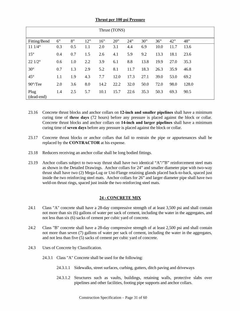
Construction Specification – Page 31 of 60
Thrust per 100 psi Pressure Thrust (TONS)
Fitting/Bend 6” 8” 12” 16” 20” 24” 30” 36” 42” 48” 11 1/4° 0.3 0.5 1.1 2.0 3.1 4.4 6.9 10.0 11.7 13.6
15° 0.4 0.7 1.5 2.6 4.1 5.9 9.2 13.3 18.1 23.6
22 1/2° 0.6 1.0 2.2 3.9 6.1 8.8 13.8 19.9 27.0 35.3
30° 0.7 1.3 2.9 5.2 8.1 11.7 18.3 26.3 35.9 46.8
45° 1.1 1.9 4.3 7.7 12.0 17.3 27.1 39.0 53.0 69.2
90°/Tee 2.0 3.6 8.0 14.2 22.2 32.0 50.0 72.0 98.0 128.0
Plug 1.4 2.5 5.7 10.1 15.7 22.6 35.3 50.3 69.3 90.5 (dead-end) 23.16 Concrete thrust blocks and anchor collars on 12-inch and smaller pipelines shall have a minimum
curing time of three days (72 hours) before any pressure is placed against the block or collar. Concrete thrust blocks and anchor collars on 14-inch and larger pipelines shall have a minimum curing time of seven days before any pressure is placed against the block or collar.
23.17 Concrete thrust blocks or anchor collars that fail to restrain the pipe or appurtenances shall be
replaced by the CONTRACTOR at his expense. 23.18 Reducers receiving an anchor collar shall be long bodied fittings. 23.19 Anchor collars subject to two-way thrust shall have two identical “A”/”B” reinforcement steel mats
as shown in the Detailed Drawings. Anchor collars for 24” and smaller diameter pipe with two-way thrust shall have two (2) Mega-Lug or Uni-Flange retaining glands placed back-to-back, spaced just inside the two reinforcing steel mats. Anchor collars for 26” and larger diameter pipe shall have two weld-on thrust rings, spaced just inside the two reinforcing steel mats.
24 - CONCRETE MIX 24.1 Class "A" concrete shall have a 28-day compressive strength of at least 3,500 psi and shall contain
not more than six (6) gallons of water per sack of cement, including the water in the aggregates, and not less than six (6) sacks of cement per cubic yard of concrete.
24.2 Class "B" concrete shall have a 28-day compressive strength of at least 2,500 psi and shall contain
not more than seven (7) gallons of water per sack of cement, including the water in the aggregates, and not less than five (5) sacks of cement per cubic yard of concrete.
24.3 Uses of Concrete by Classification. 24.3.1 Class "A" Concrete shall be used for the following: 24.3.1.1 Sidewalks, street surfaces, curbing, gutters, ditch paving and driveways
24.3.1.2 Structures such as vaults, buildings, retaining walls, protective slabs over pipelines and other facilities, footing pipe supports and anchor collars.
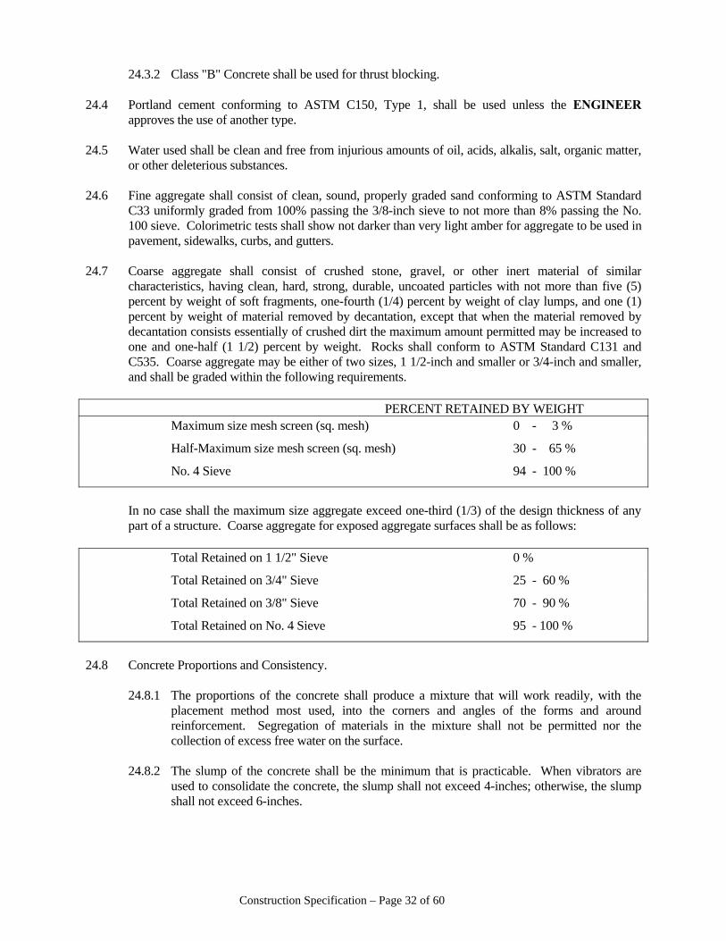
Construction Specification – Page 32 of 60
24.3.2 Class "B" Concrete shall be used for thrust blocking. 24.4 Portland cement conforming to ASTM C150, Type 1, shall be used unless the ENGINEER
approves the use of another type. 24.5 Water used shall be clean and free from injurious amounts of oil, acids, alkalis, salt, organic matter,
or other deleterious substances. 24.6 Fine aggregate shall consist of clean, sound, properly graded sand conforming to ASTM Standard
C33 uniformly graded from 100% passing the 3/8-inch sieve to not more than 8% passing the No. 100 sieve. Colorimetric tests shall show not darker than very light amber for aggregate to be used in pavement, sidewalks, curbs, and gutters.
24.7 Coarse aggregate shall consist of crushed stone, gravel, or other inert material of similar
characteristics, having clean, hard, strong, durable, uncoated particles with not more than five (5) percent by weight of soft fragments, one-fourth (1/4) percent by weight of clay lumps, and one (1) percent by weight of material removed by decantation, except that when the material removed by decantation consists essentially of crushed dirt the maximum amount permitted may be increased to one and one-half (1 1/2) percent by weight. Rocks shall conform to ASTM Standard C131 and C535. Coarse aggregate may be either of two sizes, 1 1/2-inch and smaller or 3/4-inch and smaller, and shall be graded within the following requirements.
PERCENT RETAINED BY WEIGHT Maximum size mesh screen (sq. mesh) 0 - 3 %
Half-Maximum size mesh screen (sq. mesh) 30 - 65 %
No. 4 Sieve 94 - 100 %
In no case shall the maximum size aggregate exceed one-third (1/3) of the design thickness of any
part of a structure. Coarse aggregate for exposed aggregate surfaces shall be as follows: Total Retained on 1 1/2" Sieve 0 %
Total Retained on 3/4" Sieve 25 - 60 %
Total Retained on 3/8" Sieve 70 - 90 %
Total Retained on No. 4 Sieve 95 - 100 %
24.8 Concrete Proportions and Consistency. 24.8.1 The proportions of the concrete shall produce a mixture that will work readily, with the
placement method most used, into the corners and angles of the forms and around reinforcement. Segregation of materials in the mixture shall not be permitted nor the collection of excess free water on the surface.
24.8.2 The slump of the concrete shall be the minimum that is practicable. When vibrators are
used to consolidate the concrete, the slump shall not exceed 4-inches; otherwise, the slump shall not exceed 6-inches.
Construction Specification – Page 33 of 60
24.8.3 The methods of measuring concrete materials shall be such that the proportions can be accurately controlled and easily checked. Measurement of materials for ready-mixed concrete shall conform to Specifications for Ready-Mixed Concrete (ASTM C94).
24.9 Mixing and Hauling Concrete. Concrete shall be mixed in a batch mixer of a type designed to
insure uniform and thorough distribution of the materials throughout the mix. Its size shall be such as to produce a volume of concrete consistent with demands of each pour. It shall be equipped with a water-metering device for accurate measurement of water. Charges of cement shall be by full sacks of cement; the use of fractional sacks, or reclaimed cement, will not be acceptable. All concrete shall be mixed for a period of not less than five (5) minutes after all materials, including the mixing water, have been placed in the drum. The entire contents of each batch shall be discharged from the drum before any material for the succeeding batch is placed therein. When the mixing operation for each period is completed, the mixer drum shall be cleaned thoroughly. Concrete shall be deposited within forty-five (45) minutes after it is mixed.
24.10 If the CONTRACTOR elects to use a central mixing plant, he shall provide sufficient hauling
equipment, properly designed to prevent segregation and loss of mortar, and to permit discharge without segregation. When the hauling and placing operation for each period is completed, the hauling equipment shall be cleaned thoroughly.
24.11 Ready-mix concrete may be used at the option of the CONTRACTOR if acceptable concrete is
delivered. Ready-Mix concrete shall conform to ASTM Standard C94 and to applicable portions of these specifications for on-site mixing. The concrete shall be delivered and placed within forty-five (45) minutes after all materials, including mixing water, shall have been placed in the mixing drum. The CONTRACTOR shall obtain from the supplier of the ready-mixed concrete, the supplier's agreement to inspection by the ENGINEER, to the full extent deemed necessary by the ENGINEER.
24.12 Testing Concrete. As the placement of concrete progresses, the ENGINEER may take samples of
the concrete for testing. The CONTRACTOR shall provide whatever assistance required by the ENGINEER in collecting and preparing samples for testing. Sampling shall be in accordance with ASTM Standard C172.
24.12.1 Slump tests shall be made in accordance with ASTM Standard C143. 24.12.2 Compression test specimen shall be prepared and cured in accordance with ASTM Standard
C31. Specimens shall be tested in accordance with ASTM Standard C39. 24.13 All reinforcing bars shall be "Deformed Carbon-Steel Bars for Concrete Reinforcement”
conforming to ASTM Designation A615. Deformed bars shall be intermediate grade with minimum yield point of 40,000 psi, or greater if otherwise specified.
24.14 Lapping of reinforcement bars shall be a minimum of 30 diameters in length. Welding of
reinforcing bars is not allowed unless specifically approved by the CAW ENGINEER. Welding of reinforcement bars must conform to applicable ANSI/ASTM/AWS standards and requirements.
24.15 When the volume of concrete required at the work site is less than one-third (1/3) cubic yard, mixing
may be accomplished by hand tool methods. The concrete shall be mixed in a clean, watertight vessel to the extent necessary to assure that the cement, aggregate, and water are thoroughly integrated. The mix shall be at least one (1) part Portland cement to two (2) parts coarse aggregate, as specified in Section 24.7 above and two (2) parts sand, as specified in Section 24.6 above. Only that amount of water required to provide a stiff, workable mix shall be used. The strength requirements specified in Sections 24.1 and 24.2, herein, apply.
Construction Specification – Page 34 of 60
25 - PLACEMENT & FINISHING CLASS "A" CONCRETE 25.1 Forms shall be constructed before placement of any concrete unless otherwise authorized by the
ENGINEER. 25.1.1 Forms shall conform to shapes, lines, and dimensions of the members as specified on the
Plans, or as required to conform to the original shape and dimensions in the case of replacement structures, and shall be sufficiently tight to prevent leakage of mortar. They shall be properly braced or tied together so as to maintain position and shape. They may be constructed of any material with sufficient strength which will provide the finished work a satisfactory surface; however, metal forms will not be permitted for concrete which will be exposed on any of the completed work, except upon the specific approval of the ENGINEER.
25.1.2 In those cases in which paved surfaces are being replaced such as sidewalks, driveways,
curb, gutter, etc., the edge of adjacent existing surfaces must be cut straight and smooth using a concrete saw or other suitable tool. The forms shall be constructed in such manner that a smooth concrete surface is produced which matches the existing surfaces on each side.
25.1.3 Forms shall be removed in such a manner as to insure the complete safety of the structure.
When the structure is supported on shores, the removable floor forms, beams and girder sides, and column and similar vertical forms may be removed after 96 hours, providing the concrete will not be damaged. In no case shall supporting forms or shoring be removed until members have acquired sufficient strength to support their weight and imposed loads safely.
25.1.4 Forms shall be coated with oil before placement of reinforcing steel or concrete. Excessive
coating material shall not be allowed to form or stand in puddles in the forms nor allowed to come in contact with concrete against which fresh concrete will be placed.
25.2 Placement of Reinforcement. 25.2.1 At the time concrete is placed, metal reinforcement shall be free from rust scale or other
coatings that will destroy or reduce the bond. All bars shall be shop bent, unless otherwise permitted by the ENGINEER. No bar partially embedded in concrete shall be field bent except as shown on Plans or as specifically permitted by the ENGINEER. Field bonding of rail steel bars will not be permitted.
25.2.2 Metal reinforcement shall be accurately placed according to the Plans, or as specified
herein, and adequately secured in position by concrete, metal, or other approved chairs, spacers or ties.
25.2.3 No splices of reinforcement shall be made except as shown on the Plans, or as specified, or
as authorized by the ENGINEER. All welding shall conform to the American Welding Society's Recommended Practices for Welding Reinforcing Steel, Metal Inserts, and Connections in Reinforced Concrete Construction (AWS D12.1), unless otherwise authorized by the ENGINEER. All laps and splices shall be in accordance with ACI 318, using f'c = 3000 psi and fy = 60,000 psi unless otherwise shown on the Plans.
Construction Specification – Page 35 of 60
25.2.4 The reinforcement shall be protected by the thickness of concrete indicated in the Plans. Where not otherwise shown, the thickness of concrete over the reinforcement shall be as follows:
25.2.4.1 Where concrete is deposited against the ground without the use of forms--not less
than 3-inches, except wire mesh reinforcement for concrete slabs which may be within 1 ½-inches of the ground.
25.2.4.2 Where concrete is to be exposed to the weather or to the ground but placed in
forms--not less than 2-inches for bars larger than No. 5 and 1 ½-inches for No. 5 bars or smaller.
25.2.4.3 In slabs and walls not exposed to the ground or to the weather--not less than 3/4-
inch. 25.2.4.4 In all cases--at least equal to the diameter of the bars. 25.2.5 Reinforcement for Curb and Gutter. Reinforcement shall consist of #3 bars spaced at 6-inch
centers longitudinally with #4 transverse tie bars spaced at 2-foot centers. The bars shall be firmly held in place by wiring bars together. Bar chairs or other suitable steel devices shall be used to support the bars at a level 3-inches above the bottom of the concrete.
25.2.6 Reinforcement for Sidewalk, Ditch Paving, Slope Protection and Driveway Surfaces.
Reinforcement shall consist of 6-inch x 6-inch mesh, #6 gauge for driveways and #9 gauge for ditch paving, slope protection and sidewalks.
25.3 Joints and Joint Filler 25.3.1 Water stops shall be installed at no additional cost to the OWNER for construction joints in
walls and slabs below finished ground elevation, and in all water bearing structures. Where a joint is to be made, the surface of the concrete shall be thoroughly cleaned and all laitance removed. In addition, vertical joints shall be thoroughly wetted and slushed with a coat of neat cement grout immediately before placement of new concrete.
25.3.2 Expansion and contraction joints shall be provided as shown on the Plans, or if not shown
on the Plans, shall be provided as follows: 25.3.2.1 For replacement sidewalk, driveway, curb, and gutter sections, transverse joints
shall be spaced in accordance with the spacing of the adjacent surfaces. Longitudinal expansion joints shall be provided where the section being replaced abuts another structure. Contraction joints in sidewalks shall be shaped similar to existing adjacent joints.
25.3.2.2 The spacing of joints for other structures such as ditch paving, protective slabs,
etc. shall be as directed by the ENGINEER. 25.3.3 Joint Filler. 25.3.3.1 Pre-molded joint filler shall be the non-extruding type, 3/4-inch to 1-inch thick,
conforming to ASTM Designation M33, and shall be of sufficient dimension to extend through the full depth of the paved surface.
Construction Specification – Page 36 of 60
25.3.3.2 Poured joint filler shall be bituminous material conforming to ASTM Designation M18 or rubber-based compound conforming to Federal Specification SS-F-336.
25.4 Embedded items, wall fittings and anchor bolts shall be installed as shown on the Plans. Embedded
items shall be worked-out in advance of the concrete pour, giving the ENGINEER ample time for inspection of all items to be embedded.
25.5 Placing Concrete. 25.5.1 All placement of concrete must be in the presence of the ENGINEER or his representative.
The CONTRACTOR is cautioned that he may be required to remove, without compensation, any concrete placed in the absence of the ENGINEER or his representative.
25.5.2 Equipment for chuting, pumping and pneumatically conveying concrete shall be of such
size and design as to ensure a practically continuous flow of concrete at the delivery end without separation of materials. All concrete in walls and columns shall be poured through tremies unless otherwise permitted by the ENGINEER. The free fall of concrete shall be held to a minimum.
25.5.3 Concrete shall be deposited as nearly as practicable in its final position to avoid segregation
due to rehandling or flowing. The placing of concrete shall be carried on at such a rate that concrete is at all times plastic and flows readily into the spaces between the bars. No concrete that has been contaminated by foreign material shall be used, nor shall retempered concrete be used.
25.5.4 When placing is once started, it shall be carried on as a continuous operation until
placement of the panel or section is complete. When construction joints are necessary, they shall be made in accordance with Section 25.3.1 herein.
25.5.5 In placing concrete, care shall be taken that the freshly placed mass is so placed and
vibrated that there is no tendency for the coarse aggregate to segregate from the mortar, that no rock pockets are left, that the concrete flows readily around the steel and into the extremities of the forms, and the whole freshly-placed mass becomes a plastic jelly-like mass but without free water in appreciable quantity on its surface. No Class “A” concrete shall be poured without vibration with mechanical or magnetic internal vibrators.
25.5.6 Water shall be removed from place of deposit before concrete is placed unless otherwise
permitted by the ENGINEER. Before depositing concrete on or against concrete that has taken its initial set, the surface of the hardened concrete shall be broken off down to coarse aggregate and wire brushed to remove foreign matter and laitance. A layer of grout of the same cement-sand ratio as the concrete without coarse aggregate shall be placed to a thickness of one (1) to two (2) inches on the brushed surface after which the new concrete shall be placed immediately.
25.5.7 Concrete placed directly on the ground shall be placed in the forms on a compacted wetted
subgrade and shall be tamped and spaded until mortar covers the entire surface. Tamping and spading shall be given special attention in order to prevent voids in the concrete.
25.5.8 Curb and Gutter Section. The cross section of the curb and gutter shall conform to that of
adjacent sections or as directed by the ENGINEER. The surface shall be struck off smooth between templates, shaped to the required cross section, and it shall be finished with a wooden float and steel trowel and broomed to produce a uniform finish to match that of
Construction Specification – Page 37 of 60
adjacent sections. The curb and gutter shall be grooved with an approved grooving tool at intervals equal to those of adjacent sections where applicable.
25.5.9 Flat Surfaces. 25.5.9.1After the concrete has been deposited, it shall be approximately leveled and struck
off to such depth below the finish grade as required to place reinforcing mats or wire mesh, and shall be properly consolidated prior to placing the reinforcing mats or mesh, when applicable, as the case may be. Additional concrete shall be deposited and struck off to a depth above the finish grade that when properly consolidated, the surface shall conform to the line and grade required to match adjacent surfaces. The strike-off board shall be straight, free from warp, and shod on the striking surface with a steel strip. The strike-off board shall be moved forward with a combined longitudinal and transverse motion and without raising either end above the side forms during the strike-off process. A slight excess of material must be kept in front of the cutting edge at all times.
25.5.9.2Immediately following screeding and compaction operations, the slab surface shall
be tested for trueness with a straightedge. Any depressions found shall be filled with freshly mixed concrete, struck off, consolidated, and refinished. Longitudinal floating shall be done in conjunction with checking with the straight edge. The float shall not be less than 12-inches in length for walls and 48-inches in length for slabs, and from 8-inches to 10-inches in width, and shall be properly stiffened to prevent flexibility and warping. The straight-edge testing and floating operation shall continue until the entire surface is found to be free from observable departures from the straight edge, and until the surface of the slab has the required grade and contour.
25.6 Concrete Finishing. 25.6.1 Replacement Surfaces. 25.6.1.1 The concrete shall be worked with suitable tools until a finish, which matches
that of adjacent surfaces, is achieved. 25.6.1.2 Exposed aggregate finish. Scrubbed finish shall be produced on green concrete.
The surface shall be thoroughly wetted and scrubbed with stiff fiber or wire brushed, using water freely, until the surface film of mortar is removed and the aggregate is uniformly exposed. The surface shall then be rinsed with clean water. If portions of the surface have become to hard to scrub in equal relief, dilute hydrochloric acid (commercial muriatic acid diluted with 4 to 10 parts water) shall be used after the concrete is at least two (2) weeks old to facilitate the scrubbing. The acid shall be removed within fifteen (15) minutes from the finished surface with clean water. This operation may be facilitated by casting the concrete against form faces that have been coated with a chemical retarder to keep the mortar adjacent to the form from setting. Every effort must be exerted to assure that the new surface matches any existing adjacent surfaces.
25.6.2 All exposed inner and outer (above grade) walls of structures shall be finished as follows:
Forms shall be removed from such surface as soon as structurally possible and when approved by the ENGINEER. All imperfections and depression shall then be immediately filled with mortar. The concrete surfaces shall then be machine or hand rubbed until the entire surface has a smooth, homogenous, pleasant-appearing finish of uniform texture and
Construction Specification – Page 38 of 60
color. Any delay in patching or rubbing such surfaces shall be cause for rejection of the entire structure. No mortar or wet cement shall be used in finishing except the mortar necessary to fill imperfections. Edging tools shall be used on all exposed joints and edges. All exposed corners shall be chamfered as shown on the Plans.
25.6.3 All other wall surfaces of structures shall be finished as follows: Forms shall be removed
from such surfaces as specified in Section 25.6.2 above. All imperfections and depressions shall then be immediately filled with mortar and rubbed with a wooden float or steel trowel to give a uniform appearance. Spurs shall be removed from the concrete surface. No over-all machine or hand rubbing is required.
25.6.4 Floors of structures and ditch pavement shall be trowel finished. 25.7 Curing, after placement and finishing, concrete shall be protected from damage while curing.
Provisions shall be made for maintaining concrete in moist condition for a period of at least ten (10) days after placement. A tinted spray-on curing compound shall be used unless otherwise approved by the ENGINEER.
25.8 After removal of forms and finishing, as specified elsewhere herein, backfill shall be placed around
the structure and thoroughly compacted. 25.9 Cold-Weather Requirements. 25.9.1 Concrete shall not be placed when the ambient temperature is below 40°F, nor when the
concrete is likely to be subjected to freezing temperatures before final set has occurred. Concrete footings or slabs shall not be placed over frozen ground. The temperatures of the concrete when placed shall not be less than 45°F. Heated materials shall be free of ice, snow, and frozen lumps before entering the mixer. Methods and equipment for the heating of materials shall be subject to the ENGINEER'S approval. Suitable means shall be provided for maintaining the concrete at a temperature of at least 45°F for not less than 96 hours after placing.
25.9.2 Special methods shall be used to protect concrete floor slabs in cold weather to prevent frost
from entering the concrete (or fill under floor slabs) until the building or structure is enclosed and heat is provided. Methods shall include covering of slabs with hay or other insulating material, protection of insulation from wetting with tarpaulins, introduction of heat, construction of enclosures, or other methods, depending upon the severity of the weather. The housing, covering or other protection used in connection with curing shall remain in place and intact at least 24 hours after the artificial heating is discontinued. Methods to be used shall be proposed in advance of the work and shall be approved by the ENGINEER. Salt, calcium, chloride, or other chemicals shall not be mixed with the concrete to prevent freezing.
25.9.3 Any and all concrete damaged by freezing shall be removed to the satisfaction of the
ENGINEER, and replaced, all at the expense of the CONTRACTOR. 25.10 Hot Weather Requirements. 25.10.1 In hot weather, suitable precautions shall be taken to avoid drying of the concrete prior to
finishing operations. Use of windbreaks, sunshades, fog sprays, or other devices shall be provided as directed by the ENGINEER.
Construction Specification – Page 39 of 60
25.10.2 Concrete deposited in hot weather shall not have a placing temperature that will cause difficulty from loss of slump, flash set, or cold joints. Concrete temperatures shall be less than 90°F unless the ENGINEER permits higher temperatures.
25.11 The use of setting compounds, retarding compounds, or other additives shall be prohibited unless
approval of its use has been secured, in advance, from the ENGINEER.
26 - BACKFILL & BEDDING 26.1 All trenches and other excavations shall be backfilled as soon as possible after installation of the
pipelines and appurtenances. It may be necessary to backfill only a portion of the trench in order to allow adequate curing of concrete. The CONTRACTOR shall limit all open trenches to a maximum of 300 linear feet along public streets/roads/highways and shall completely backfill all trenches daily. Temporary road plating of open trenches in paved areas is allowed if so approved by the street/road/highway department. To ensure that proper materials and/or workmanship have been utilized, the OWNER/ENGINEER/INSPECTOR may require that trenches and other excavations not be backfilled until direct observation/inspection of the work has been made.
26.2 Backfilling under the pipe shall be in accordance with Section 10, herein. 26.3 Donafill or wet and/or frozen material shall not be used for backfilling. 26.4 Unless Type 4 or Type 5 Bedding is specified (Section 27 herein), backfill shall be in accordance
with Section 26.5 and 26.6 herein below. 26.5 When trenches pass through areas of special surfaces, backfill shall be as follows: 26.5.1 When trenches pass through EXISTING paved roads, streets, alleys, driveways, and/or
parking lots, the trench shall be backfilled from trench bottom to an elevation three (3) inches below the finished surface with compacted Class 7 crushed stone. The first layer of crushed stone shall be placed loose up to the springline of the pipe (not exceeding nine (9) inches per layer), and be carefully tamped and haunched around the bottom half of the pipe. Subsequent crushed stone shall be placed in loose lifts up to nine (9) inches thick and compacted to 95% modified proctor density before placement of the next loose lift of crushed stone. The trench shall be capped with a minimum of three (3) inches of compacted asphaltic concrete cold mix to serve as a temporary driving surface until permanent repairs are made.
26.5.2 When trenches pass through PROPOSED paved roads, streets, alleys, driveways, and/or
parking lots (when such proposed improved surfaces are shown in the plans), the trench shall be backfilled from its bottom to the proposed finished grade with compacted Class 7 crushed stone. Backfill and compaction shall proceed as specified in Section 26.5.1 above, except the temporary cap of cold mix is not required.
26.5.3 When trenches pass through existing sidewalks, the trench shall be backfilled from trench
bottom to an elevation three (3) inches below the finished surface with compacted select native material. Backfill and compaction of the select material shall proceed as specified in Section 26.5.1 above, except the temporary cap shall be three (3) inches of compacted Class 7 crushed stone or asphaltic concrete cold mix.
26.6 When trenches are not located within areas of existing or proposed improved or special surfaces,
backfill shall be with native material. From the bottom of the trench (or top of special backfill) to an
Construction Specification – Page 40 of 60
elevation at least twelve (12) inches above the top of the pipe, backfill shall be select native material with no rocks or clogs exceeding 2 1/2 inches in any dimension. Additional native material shall be placed as backfill in the trench and compacted before reaching the top of the trench either by flooding with water or rolled by passing the wheel or track of a heavy piece of equipment along the trench line in order to attain some degree of consolidation. Excess native material shall be windrowed along the trench line to provide material for future consolidation of the backfill. After complete consolidation of the backfill is achieved, any excess material shall be removed or leveled along the trench line. Backfill shall not be pushed or dumped into trench in a manner to permit free fall of material until at least two feet of cover is achieved over the top of the pipe.
26.7 The CONTRACTOR shall fill and re-fill trenches with suitable material where settlement has
occurred during the warranty period of the project. 26.8 In areas where sod, trees, shrubs, flowers or other vegetation has been removed and is to be
replanted, the top three (3”) to six (6”) inches of backfill shall be of suitable bottom land top soil. 26.9 Concrete pipe closures and other fittings or appurtenances designated by the ENGINEER shall not
be backfilled until the hydrostatic pressure and leakage tests have been completed.
27 - TYPE 4 AND TYPE 5 BEDDING 27.1 Where Type 4 or Type 5 bedding is specified, the trench shall be excavated to a depth nine inches
(9”) below plan grade. The trench width shall conform to the requirements of Section 10.3 herein. Nine inches (9”) of granular material (described in Section 27.5 below) shall be placed in the bottom of the trench in two (2) equal lifts. Each lift shall be consolidated by slicing with a shovel and compacted using mechanical or pneumatic tampers. Where the soil in the bottom of the trench is wet or soft enough to intrude into the voids of granular material placed on it, a layer of coarse sand four inches (4”) thick shall be placed in the trench bottom and consolidated, followed by at least five inches (5”) of granular material.
27.2 Type 4 Bedding. After the pipe is placed on the consolidated granular material in the bottom of the
trench, at least six inches (6”) of granular material shall be deposited on each side of the pipe and thoroughly tamped and rammed around the pipe using hand, mechanical, or pneumatic tampers. A layer of firmly bedded plywood or sheeting, to be left in place, shall be placed along the sides of the trench whenever the soil is wet and soft. The sheeting shall extend to a height of four feet (4’), or six inches (6”) above the pipe, whichever is greater. The trench, from the top of the granular material to a point six inches (6”) above the pipe, shall be backfilled with select material consisting of fine loose earth or sand free from clods or rocks larger than 2 1/2-inches in any dimension and of proper moisture content for maximum consolidation. This material shall be deposited in layers not to exceed four inches (4”) on both sides of the pipe and thoroughly and carefully tamped and rammed around the pipe using hand, mechanical or pneumatic tampers. Compaction shall continue until 90 percent of maximum density as determined by the Modified Proctor Compaction Test has been achieved.
27.3 Type 5 Bedding. After the pipe is placed on the consolidated granular material in the bottom of
trench, additional granular material shall be deposited in lifts not to exceed six inches (6”) on both sides of the pipe and thoroughly tamped and rammed around the pipe using hand, mechanical, or pneumatic tampers until the material has been brought up to a point a minimum of six inches (6”) above the top of the pipe. A layer of firmly bedded plywood or sheeting, to be left in place, shall be placed along the sides of the trench whenever the soil is wet and soft. This sheeting material shall extend to a height of four feet (4’), or six inches (6”) above the pipe, whichever is greater.
Construction Specification – Page 41 of 60
27.4 The remainder of the backfill shall be in accordance with Section 26 herein. 27.5 The granular material shall be crushed stone or pea gravel conforming to ASTM C33-67, Size No.
7, having the following grade by weight: Sieve Size Percent Retained 3/4 inch 0 %
1/2 inch 0 – 10 %
3/8 inch 30 – 60 %
No. 4 85 – 100 %
No. 8 95 – 100 %
27.6 All Type 4 and Type 5 Bedding shall be inspected by the ENGINEER or his representative before
backfilling the trench.
28 – REPLACEMENT OF SPECIAL SURFACES 28.1 The CONTRACTOR shall replace or repair all special surfaces removed or disturbed during the
progress of the work as shown in the detailed drawings. 28.2 All replacement or repairs of special surfaces within the right-of-way of public streets or roads must
conform to requirements of and be approved by the state, county or local authority having jurisdiction. Concrete surfaces, except street pavement, shall be constructed in accordance with Sections 24 and 25 herein, unless otherwise directed by state, county or local authorities having jurisdiction.
28.3 The materials used shall be of the same type as that removed or be approved by the ENGINEER or
state, county, or local authority having jurisdiction. 28.4 The following shall be considered minimum requirements with respect to replacing asphaltic
concrete pavement other than public road, street, or alley pavement. 28.4.1 The trench shall be backfilled in accordance with Section 26 herein. 28.4.2 The pavement thickness shall be at least as thick as adjacent pavement but in no case shall it
be thinner than two inches (2”). 28.4.3 Before placement of new surface material, all excess material (temporary cold mix asphaltic
concrete, crushed stone, soil, etc.) shall be removed to a depth at least equal to the specified thickness of the replacement surface. The bottom surface on which the replacement material is to be placed shall be finished smooth and any wet material and debris removed.
28.4.4 Preparation and Priming. No bituminous material shall be placed upon a surface having
excess moisture or when general weather conditions are not suitable. The edges of existing pavement surface shall be cut smooth and vertical along a horizontal straight line. After removal of excess material from the trench, the bottom surface shall be finished smooth and rolled with a flat-wheel, pneumatic tired roller or other equipment which will compact the
Construction Specification – Page 42 of 60
uppermost portion of the trench. Paved areas adjacent to the trench shall be cleaned by broom sweeping. The prime coat shall be applied at a rate of 0.40 gallons per square yard. The vertical edges of existing pavement shall be primed.
28.4.5 Application of Surface Course. Restrictions relative to moisture and weather conditions
cited in Section 28.4.4 above apply. The mixture shall be transported to the work site in tight vehicles with canvas cover over the cargo compartment to retard heat loss. The mixture shall be delivered at a temperature of 275°F to 325°F. The mixture shall be spread by hand or suitable machine immediately after delivery to the work site to a depth that will match adjacent pavement surfaces after rolling. The mixture shall be thoroughly compacted by passing a steel wheel roller over the surface course immediately after being spread. The mixture shall be continuously rolled until all roller marks are eliminated and no further compaction is possible. The final surface shall match adjacent pavement surfaces and there shall not be any depressions or raised surfaces across the trench.
28.4.6 All preparatory work must be inspected by the ENGINEER before placement of asphaltic
concrete. 28.5 SIDEWALKS – Sidewalks removed shall be reconstructed as per the requirements of the state,
county, or municipal authorities have jurisdiction. Sidewalks at intersections and designated mid-block crosswalks shall be reconstructed with handicapped ramps.
28.6 The CONTRACTOR shall replace any traffic markings removed during the WORK. 28.7 Calculation of the total payable width of surface repair shall be based on the minimum payable
widths as stated in Section 39 herein. Damage and repair of special surfaces beyond the payment limits specified shall be made by the CONTRACTOR at his expense. All special surface repairs must meet the approval of the agency having jurisdiction.
29 - TEMPORARY REPAIRS TO SPECIAL SURFACES 29.1 Unless permanent repairs to paved street/road/highway surfaces can be started immediately after
backfilling the trench, the CONTRACTOR shall place suitable asphalt material in the trench. The surface shall match the surfaces on each side of the trench and shall be in accordance with applicable state, county, or local requirements and be a minimum of three inches (3”) thick as specified in Section 26 herein. When heavy steel road plates are used in lieu of immediate backfill or used to cover and protect fresh concrete or flowable fill, all edges of the road plates shall be filleted and ramped with cold mix asphalt. The purpose of the asphalt shall be to both hold the plate in place and provide a smooth transition for vehicular traffic.
29.2 The above provisions shall apply to driveways, sidewalks, parking lots, or other paved areas
whenever the backfill will not adequately support vehicular traffic, whenever dust from the trench creates a nuisance, or whenever the trench is a hazard.
29.3 Detours shall have a gravel, crushed stone, or asphalt surface. Dust shall be controlled by the
application of asphalt or water. 29.4 The CONTRACTOR shall maintain all temporary surfaces in good condition until permanent
repairs are complete.
Construction Specification – Page 43 of 60
29.5 Immediately following any significant rain or snowfall event, the CONTRACTOR shall check all temporary repairs and place additional material as needed to maintain a passable and acceptable surface.
30 - CONNECTIONS TO DISTRIBUTION SYSTEM 30.1 All connections to the existing distribution system must be accomplished in the presence of the
ENGINEER or his representative. 30.2 In cases where completing the connection will disrupt service to customers, the CONTRACTOR
shall notify the ENGINEER at least two (2) days in advance of the work. The customers whose service will be disrupted shall be notified by the OWNER with the assistance of the CONTRACTOR. The CONTRACTOR shall plan the work so that disruption of service is held to a minimum. The plan must be satisfactory to the ENGINEER.
30.3 After connections have been completed, the valves shall remain tightly closed until all testing and
sterilization is complete. The ENGINEER shall place a locking lid on the valve box. Connecting valves shall remain closed until otherwise directed by the ENGINEER.
31- FILLING PIPELINES 31.1 After the pipelines and appurtenances have been installed, all concrete thrust blocking has cured
adequately and upon approval of the ENGINEER, the pipelines shall be filled with water. 31.2 In order to prevent circulation of water through the new pipelines back into the distribution system,
new pipeline shall only be filled through approved “fill connections” installed and constructed by the CONTRACTOR as shown in the Standard Details or as directed by the ENGINEER.
31.3 Valves other than fill connection valves shall not be used to fill new pipelines without the specific
approval of the ENGINEER. Any such valve shall be operated only in the presence of the ENGINEER and shall be slowly and only partially opened.
31.4 All air shall be expelled from the pipeline by opening fire hydrants and/or other openings installed at
the pipe line crests by the CONTRACTOR. The location and number of such openings shall be as shown on the Plans or as directed by the ENGINEER. Water draining from the openings shall be directed to adequate drainage structures so as not to create a nuisance and to avoid damage to other facilities, structures, and/or property. The CONTRACTOR shall be responsible for any damages.
31.5 Fill assemblies, blowoffs, and sampling point assemblies shall be disassembled to their below
ground configuration within one week of final use.
32 - CLEANING LARGE PIPELINES 32.1 Before disinfection and hydrostatic pressure and leakage testing (see Section 33 herein), pipelines
16-inches in diameter and larger shall be cleaned by forcing a resilient high density polyurethane foam "cleaning pig" through each segment of the pipeline by water pressure to remove any dirt or other foreign matter from the pipeline. The "pig" shall be Style III, Type C (blue, plain criss-cross), manufactured by Knapp, Inc., Houston, Texas, or equal, in good condition and shall be at least two (2%) percent larger in diameter than the inside diameter of the pipe line being cleaned.
Construction Specification – Page 44 of 60
32.2. The "pig" shall be inserted in the first length of pipe installed in each segment of pipeline. After installation of the pipeline segment to be cleaned, the pipeline shall be filled at a point downstream of the "pig". The "pig" shall be forced through the pipeline by applying water pressure to the rear of the "pig" and opening blowoff valves or fire hydrants downstream of the "pig". Valve at blowoff points shall be closed immediately prior to the "pig" passing.
32.3 Based on past experience, the "pig" will negotiate bends and tees in the pipeline and may also be
forced through the pipeline backwards after a pass forward. Openings in the pipeline, as shown on the Plans for removing the "pig", are based on this assumption. If the CONTRACTOR is unable to clean the pipeline, utilizing the openings provided, additional openings shall be provided by the CONTRACTOR, upon approval of the ENGINEER, at the expense of the CONTRACTOR.
32.4 If the need for more than one pass of the "pig" through the pipeline is indicated, the
CONTRACTOR shall make additional passes as directed by the ENGINEER. 32.5 Drainage at blowoff points shall be provided so as not to create a nuisance and to avoid damage to
other facilities, structures, and/or property. The CONTRACTOR shall be responsible for any damages.
33 - HYDROSTATIC PRESSURE and LEAKAGE TESTS 33.1 Testing shall begin within five (5) days after the completion of the installation of the water main (on
a per main or per section/area basis). Once pressure testing is begun, it shall be vigorously pursued until complete. After the pipelines or isolated sections of the pipeline have been filled with water and air purged, the pressure shall be increased to the test pressure by means of a pump.
33.2 The CONTRACTOR shall furnish a pump and appurtenances as described in Section 34 herein.
The OWNER will furnish the meter and pressure gauge after the CONTRACTOR has satisfied himself that the line will pass the test. The CONTRACTOR shall furnish all labor for conducting the tests.
33.3 The test pressure shall be 225 psi at the highest point of the pipeline segment being tested or as
otherwise specified by the ENGINEER. All pipelines, service lines, and appurtenances shall be tested. The pressure test shall be documented on the Central Arkansas Water PRESSURE AND LEAKAGE TEST form.
33.4 The duration of the hydrostatic leakage test shall be two (2) hours or as specified by the
ENGINEER. 33.4.1 The duration of the hydrostatic leakage test on tapping sleeves/saddles shall be thirty (30)
minutes at 225 psi with zero leakage. 33.5 The source of water for the pump suction shall be potable water from the OWNER'S distribution
system. The vessel used must be approved by the ENGINEER. 33.6 All interior valves including guardian valves on fire hydrants and other appurtenances shall be open
during all tests. 33.7 After the specified test pressure has been applied the entire pipeline shall be checked in the presence
of the ENGINEER giving particular attention to that part of the pipeline and those appurtenances that are exposed.
Construction Specification – Page 45 of 60
33.8 If leaks are apparent, the CONTRACTOR shall, at his own expense, perform whatever work and/or replace whatever material that is required in order to remedy the defect and stop the leaks. All corrective work shall be approved by the ENGINEER. See Section 11.17 herein.
33.9 After the CONTRACTOR has taken the necessary action to repair or replace any part of the
pipeline or appurtenances where leaks were apparent or if no leaks were apparent, the pipelines shall be subjected to a leakage test at the pressure specified with a meter inserted in the test pump discharge line.
33.10 A. The maximum leakage per hour for jointed pipe (ductile iron, PVC, concrete pipe, etc.) shall be
as calculated from the following formula:
All rubber gasket or O-ring joints
___ Q = LD √ P 148,000
Q = Quantity of makeup water (gallons per hour) L = Length of pipe section being tested (feet) D = Nominal pipe diameter (inches) P = Test pressure (psi); 225 psi or as specified by the ENGINEER B. The maximum leakage per hour for non-jointed pipe (welded steel, welded PVC, welded HDPE,
etc., and containing gasket-jointed connections for fittings, valves, etc.) shall be as calculated form the following formula:
___
Q = ND √ P 7,400
Q = Quantity of makeup water (gallons per hour) N = Summation of mechanical and push-on gasket joints in length of pipe tested D = Nominal pipe diameter (inches) P = Test pressure (psi); 225 psi or as specified by the ENGINEER
33.10.1 The test pressure shall not vary by more than ± five (5) psi for the duration of the test. During the duration of the two hour test, if the test pressure drops more than 5.0 psi from the start pressure, the test shall be terminated and considered failure due to assumed leaks in the tested pipe section. If the pressure rises beyond the allowed 5 psi variance, the test shall be terminated and remaining air shall be purged from the pipeline.
33.10.2 Upon completion of a two hour test where the test pressure did not vary by more than
± five (5) psi, the CONTRACTOR shall determine the leakage amount by measuring the amount of “make-up” water necessary to restore the original starting pressure.
33.11 If any test of pipe laid discloses leakage greater than the allowable leakage as calculated from the
above formula(s), the CONTRACTOR shall, at his expense, locate the leak or leaks and perform whatever work and/or replace whatever material that is required in order to remedy the defect(s) and stop the leak(s). All corrective work must be approved by the ENGINEER. Tests on tapping sleeves/saddles must have zero leakage to be considered successful.
Construction Specification – Page 46 of 60
34 - TEST PUMP 34.1 The CONTRACTOR shall provide a water pump for testing the mains hydrostatically. The pump
shall have the following features: 34.1.1 Designed so that the required test pressures can be attained. 34.1.2 RESERVED 34.1.3 The pump discharge shall be equipped with the following, in the order listed from the pump
outward (see Standard Detail Sheet): (a) Check valve arranged so as to prevent flow back toward pump. (b) Adjustable pressure regulating device capable of maintaining discharge pressure at
a constant level. (c) Valved exhaust outlet. (d) Section of flexible hose - length sufficient that ends of hose rests on ground. (e) Outlet for pressure gauge. Outlet shall be equipped with valve and surge
dampening device. Connection for gauge shall be 1/4" F.I.P. The pressure gauge will be furnished by the OWNER.
34.1.4 The pump suction shall be equipped with the following from the pump outward (see
Standard Detail Sheet): (a) Suction pipe. (b) Straight meter coupling - 1/2" M.I.P. x 5/8" Meter Nut. (c) 5/8" meter - furnished by owner (d) Straight meter coupling - 1/2" M.I.P. x 5/8" Meter Nut. (e) End screen to prohibit entry of foreign matter if pump suction is connected to a
vessel instead of on a water main. 34.2 The CONTRACTOR shall provide all other necessary connections for connecting pump from the
suction source and to the main being tested.
35 - DISINFECTING PIPE LINES & APPURTENANCES 35.1 Testing shall begin within five (5) days after the completion of the pressure testing of the water main
(on a per main or per section/area basis). Blowoff and sample points shall be constructed by the CONTRACTOR as shown on the Plans or as directed by the ENGINEER. Fire hydrants shall be utilized as blowoff points whenever possible. Fire hydrants are not satisfactory for sample points. Openings for sample points shall be 1" copper riser pipe that extends well above the surface, as shown on the Standard Details. A flushing plan shall be so designed so that all samples may be taken on each trip. The lines shall not be considered acceptable until two (2) consecutive samples taken twenty-four (24) hours apart are negative. Sampling may commence only Monday through Thursday. First samples may not be collected on Fridays, Saturdays, Sundays, and official holidays.
35.2 There are two acceptable methods of disinfecting: continuous feed method using liquid chlorine or
calcium hypochlorite and the slug method using liquid chlorine or calcium hypochlorite. The slug method applies to large mains and shall be used only on approval of the ENGINEER. Liquid chlorine shall be used only when the CONTRACTOR has suitable equipment available and
Construction Specification – Page 47 of 60
employees who are familiar with the physiological, chemical and physical properties and who are properly trained and equipped to handle any emergency that may arise. If, in the opinion of the ENGINEER, the equipment is inadequate or the personnel are not qualified, this method shall not be used.
35.3 When the continuous feed or slug method is to be used, the pipelines and appurtenances shall be
thoroughly flushed prior to disinfecting. The flushing plan shall be approved by the ENGINEER. The ENGINEER may halt or reduce flushing if the distribution system pressures are reduced by the flushing operations.
35.4 The operation of valves shall be in accordance with the provisions of Section 31, herein. 35.5 The CONTRACTOR is reminded that chlorine is a powerful oxidant and reacts readily with
foreign substances. All chlorine compounds shall be handled and stored in accordance with manufacturer's recommendations. Breathing of chlorine gas can be fatal. Hypochlorite solutions should not come into contact with skin or clothing. Containers used for mixing hypochlorite solution shall be clean and dry.
35.6 When the continuous flow method is used, the final concentration of chlorine inside the main shall
be 50 parts per million. When the slug method is used, the concentration of chlorine entering the pipeline shall be at least 300 to 400 parts per million (ppm) and be of sufficient size/length to provide a minimum of two (2) hours of contact time as it flows through the pipeline. The strength/concentration of the slug shall be monitored as it flows through the pipeline and at no time shall it be allowed to drop below 100 ppm. If at any time the concentration of the slug nears 100 ppm, the flow shall be stopped, chlorination equipment shall be relocated to the head of the slug, and as flow resumes, chlorine shall be applied to restore the chlorine concentration of the slug to at least 300 ppm.
35.7 Calcium hypochlorite shall contain at least 60% available chlorine by weight in granular form. 35.8 When the continuous feed or slug method is used and the source of the chlorine is calcium
hypochlorite, a solution of hypochlorite and water shall be prepared by mixing thoroughly in a suitable container. The mix shall contain one (1) pound of calcium hypochlorite per gallon of water. A suitable pump shall be provided for pumping this solution into the pipelines to be disinfected. This pump shall be equipped with a flow-measuring device.
35.9 When liquid chlorine is used, the equipment for injection shall consist of a solution feed chlorinator
in combination with a booster pump for injecting the chlorine-gas water solution into the pipeline. Introduction of chlorine-gas directly from the supply cylinder shall not be permitted. The pump shall be equipped with a flow-measuring device.
35.10 During application of any chlorine solution, care shall be taken to assure that the solution does not
flow back into the distribution system. 35.11 The procedure for disinfecting by the continuous flow method shall be as follows: 35.11.1 The flow through the pipeline and the solution flow shall be regulated so that the required
concentration of chlorine is attained. The flow through the main shall be measured by using a pitot gauge or meter.
35.11.2 The introduction of the solution shall be continuous until the desired concentration is
attained throughout the pipe line system. The concentration shall be checked by the Drop Dilution Method.
Construction Specification – Page 48 of 60
35.11.3 After the required concentration has been attained all internal valves shall be operated in
order to assure that the solution comes in contact with all appurtenances. 35.11.4 The solution shall remain in the pipe line system for twenty-four (24) hours after which the
pipelines shall be thoroughly flushed. The chlorine concentration shall be checked before flushing. If the concentration is less than 25 parts per million, the disinfecting procedure shall be repeated if directed by the ENGINEER.
35.12 The procedure for disinfecting by the slug method shall be the same as the continuous flow method
except that the flow rates shall be regulated so that the specified concentration of chlorine shall be in contact with all parts of the pipe line for at least two (2) hours.
35.13 Disinfecting by the tablet method is not allowed by the Arkansas Department of Health. 35.14 After final flushing, samples of water shall be collected from the sample points provided by the
CONTRACTOR and tested by the OWNER. The CONTRACTOR shall provide any assistance required in collecting the samples.
35.15 If any of the samples collected are positive, the disinfecting procedures shall be repeated as directed
by the ENGINEER until negative samples are collected. Only the continuous flow or slug method may be used.
35.16 The cost of water used for flushing after positive samples have been collected shall be deducted
from amounts due the CONTRACTOR. The amount used shall be determined by measurements of flow using a pitot gauge. Payment shall be based on the lowest prevailing water rate.
35.17 Payments to the CONTRACTOR (or DEVELOPER if a SPECIAL CONTRACT) shall be
reduced by $30.00 per sample for each positive sample collected to cover the cost of collecting and testing the samples.
35.18 Any chlorinated water release that would cause a chlorine residual above 0.10 ppm in a body of
water containing any aquatic life forms shall be de-chlorinated as needed to prevent the resultant chlorine level from exceeding the 0.10 ppm limit. Chemicals used in the de-chlorination process shall not also produce other water qualities that would be harmful to the aquatic life forms in a receiving body of water; harmful water qualities such as, but not limited to, changes in pH, dissolved oxygen concentrations, etc.
35.19 Water draining from the sampling points and flushing shall be directed to adequate drainage
structures so as not to create a nuisance and to avoid damage to other facilities, structures, and/or property. The CONTRACTOR shall be responsible for any damages.
36 - WORK PERFORMED BY OWNER 36.1 The intent of these specifications is for the CONTRACTOR to do all the work, including
connections and repair of damage to the Distribution System in this construction contract. 36.2 In emergencies, to restore service, the OWNER, with its labor forces, will assist the
CONTRACTOR when necessary at the discretion of the ENGINEER. 36.3 If the OWNER assists the CONTRACTOR for any reason, the CONTRACTOR shall pay for the
cost of this assistance, based on the actual cost of labor, equipment, materials, and overhead.
Construction Specification – Page 49 of 60
37 - DAMAGE TO DISTRIBUTION SYSTEM During the course of construction under this contract, whether by accident or carelessness, the
OWNER'S distribution system may be damaged, the CONTRACTOR shall be held responsible for this damage, and shall make immediate repairs at his expense. In event service has been disrupted, immediate repair operations shall be continuous and around the clock, if necessary.
38 - CLEAN-UP OF JOB SITE The CONTRACTOR shall remove all materials, equipment, tools, temporary structures, barricades,
trees and other vegetation that have been cut or have died as a result of the work from both public and private property along the job site. There shall be no burning on the job site unless approved, in advance, by the ENGINEER and other agencies involved. All trenches and excavations sites shall be completely compacted / settled and level with the adjacent surfaces. Unless otherwise requested by the CONTRACTOR in writing and approved by the ENGINEER, cleanup and dressup of an area shall be completed within one month of the completion of the pipe installation and testing.
39 - MEASUREMENT AND PAYMENT 39.1 Basis for payment shall be in accordance with the unit or lump-sum prices shown on the Bid Form;
or as agreed upon in writing, in the case of extra work encountered, which is outside the scope of these specifications.
39.2 No separate payment will be made for those materials and work required to make a complete
installation as shown on the Plans or indicated in these specifications, except as shown on the Bid Form. Materials and work not itemized on the Bid Form, but nonetheless required for a complete installation shall be considered subsidiary to the principle item of work and the cost thereof included in the bid price for the principle items.
39.3 Measurements for payment shall be as follows (not all of these items may be on the Bid Form): 39.3.1 Pipe and Encasement Structures – Actual slope length (Linear Feet) field measurements
furnished and installed of the various sizes and types of pipe. The laid length of inline valves shall not be included in the total pipe length unless otherwise specified. Tees, bends, polyethylene encasement, thrust blocking, nuts, bolts, glands, gaskets, pressure testing, disinfection, special trench backfill (when so designated in the Plans or in the Bid Form), and other accessories are subsidiary. If and only if so detailed in the Bid Form, Tees, Bends, Anchor Collars, and/or Thrust Blocking may be shown as separate pay items, usually only for large diameter pipe. The price for encasement pipe shall include casing spacers. The price for encasement pipe shall NOT include the carrier pipe.
39.3.2 Valves - Actual quantity (Each) furnished and installed of the various sizes and types of
valves. Box, extensions, lid, nuts, bolts, glands, gaskets, and other accessories are subsidiary to the valve. Valves for fire hydrants and blowoff assemblies shall be considered subsidiary to the complete installation of the fire hydrant.
39.3.3 Fire Hydrants and Blowoff Assemblies - Actual quantity (Each) furnished and installed.
Tees, saddles, guardian valves, valve boxes, extensions, lids, barrel extensions, thrust
Construction Specification – Page 50 of 60
blocking, drainage gravel, nuts, bolts, glands, gaskets, and other accessories are subsidiary to the fire hydrant or blowoff.
39.3.4 CITY STREET Pavement Cut and Permanent Replacement (Concrete/Asphalt) –
Area (Square Yards) measured based on length of cut times a width not to exceed the nominal pipe diameter plus 24-inches ( 2 x 12” as shown in DETAIL NO. 2A – CITY STREET of the Standard Details). Trench width beyond the nominal pipe diameter will not be measured for payment. Extra trench width, compacted stone backfill, special backfill (if shown in the Plans or in the Bid Form), concrete, reinforcement, temporary asphaltic surface, permanent asphaltic or concrete surface, and pavement cutting are subsidiary to the pavement cut and permanent replacement. Only the pavements marked and approved for removal by the ENGINEER shall be paid for. Other pavements damaged and/or removed by the CONTRACTOR shall not be paid for.
39.3.5 COUNTY ROAD Pavement Cut and Permanent Replacement (Concrete/Asphalt) –
Area (Square Yards) measured based on length of cut times a width not to exceed the nominal pipe diameter plus 48-inches ( 2 x 24” as shown in DETAIL NO. 2B – COUNTY ROAD of the Standard Details). Trench width beyond the nominal pipe diameter will not be measured for payment. Extra trench width, compacted stone backfill, special backfill (if shown in the Plans or in the Bid Form), concrete, reinforcement, temporary asphaltic surface, permanent asphaltic or concrete surface, and pavement cutting are subsidiary to the pavement cut and permanent replacement. Only the pavements marked and approved for removal by the ENGINEER shall be paid for. Other pavements damaged and/or removed by the CONTRACTOR shall not be paid for.
39.3.6 STATE HIGHWAY Pavement Cut and Permanent Replacement (Concrete/Asphalt)
Area (Square Yards) measured based on length of cut times a width not to exceed the nominal pipe diameter plus 36-inches ( 2 x 18” as shown in DETAIL NO. 1 – STATE HIGHWAY of the Standard Details). Trench width beyond the nominal pipe diameter will not be measured for payment. Extra trench width, compacted stone backfill, special backfill (if shown in the Plans or in the Bid Form), concrete, reinforcement, temporary asphaltic surface, permanent asphaltic or concrete surface, and pavement cutting are subsidiary to the pavement cut and permanent replacement. Only the pavements marked and approved for removal by the ENGINEER shall be paid for. Other pavements damaged and/or removed by the CONTRACTOR shall not be paid for.
39.3.7 IMPROVED ALLEYS, DRIVEWAYS, AND PARKING LOTS Pavement Cut and
Permanent Replacement (Concrete/Asphalt) – Area (Square Yards) measured based on length of cut times the nominal pipe diameter as shown in the Standard Details. Bridging of the trench is not normally required. If bridging is ordered in writing by the ENGINEER, the width of the bridging shall be included in the payable width for pavement repair. Trench width beyond the nominal pipe diameter will not be measured for payment. Extra trench width, compacted stone backfill, special backfill (if shown in the Plans or in the Bid Form), concrete, reinforcement, temporary asphaltic surface, permanent asphaltic or concrete surface, and pavement cutting are subsidiary to the pavement cut and permanent replacement. Only the pavements marked and approved for removal by the ENGINEER shall be paid for. Other pavements damaged and/or removed by the CONTRACTOR shall not be paid for.
39.3.8 Sidewalks Cut and Permanent Replacement – Area (Square Yards) measured based on
width times length of replacement. Only the sidewalks marked and approved for removal by the ENGINEER shall be paid for. Other sidewalks damaged and/or removed by the
Construction Specification – Page 51 of 60
CONTRACTOR shall not be paid for. Handicapped ramps shall be paid for at the same Bid Price as regular sidewalks.
39.3.9 Curb and Gutter – Length (Linear Feet) measured to nearest expansion joint within five
feet (5’) of center line of pipe, or actual quantity (Linear Feet) replaced, whichever is less. Only the curbs and gutters marked and approved for removal by the ENGINEER shall be paid for. Curb and gutter construction must meet with the approval of the governing agency / jurisdiction. Other curbs and gutters damaged and/or removed by the CONTRACTOR shall not be paid for.
39.3.10 Rock Excavation – Volume (Cubic Yards) excavated as measured by the ENGINEER or
his representative together with the CONTRACTOR or his representative. The measurement shall be taken and recorded before backfilling operations are commenced and shall include the quantity that was necessary to be removed in order to accommodate the pipe or appurtenances to the grade and alignment specified in the Plans or by the ENGINEER. No payment shall be made for overcuts, either vertically or horizontally or any rock excavation not measured by the ENGINEER. Trench width in excess of the nominal pipe diameter plus two feet (2’) shall be considered overcut.
39.3.11 Type 4 and Type 5 Bedding – Slope length (Linear Feet) of the various sizes of pipe
bedded. Payment will not be made unless Type 4 or Type 5 Bedding is specified in the Plans or directed by the ENGINEER.
39.3.12 Tapping Sleeves and Valves – Actual quantity (Each) furnished and installed of the
various sizes. Tapping sleeve, valve, valve box, lid, extensions, thrust blocking, glands, nuts, bolts, glands, gaskets, and other accessories are subsidiary.
39.3.13 Tee (Anchor Tee) and Valve – Actual quantity (Each) furnished and installed of the
various sizes. Anchor tee, valve, valve box, lid, extensions, thrust blocking, glands, nuts, bolts, glands, gaskets, and other accessories are subsidiary.
39.3.14 Swing Connection – Actual quantity (Each) furnished and installed of the various sizes.
Tapping saddle, valve, tee, bend, valve box, lid, extensions, thrust blocking, glands, nuts, bolts, glands, gaskets, and other accessories are subsidiary. Pipe used in the swing connection will be measured as per Section 39.3.1 above.
39.3.15 Fill Connection – Actual quantity (Each) furnished and installed of the various sizes.
Taps, saddles, valves, meter boxes, and accessories are subsidiary. 39.3.16 Blow-off / Sample Point – Actual quantity (Each) furnished and installed of the various
sizes. Taps, saddles, valves, meter boxes, and accessories are subsidiary. 39.3.17 Manual Air Release – Actual quantity (Each) furnished and installed of the various sizes.
Tap, saddle, valves, meter box, and accessories are subsidiary. 39.3.18 Automatic Air Release – Actual quantity (Each) furnished and installed of the various
sizes. Tap, saddle, valves, meter box, and accessories are subsidiary. 39.3.19 Combination Air/Vacuum Valve – Actual quantity (Each) furnished and installed of the
various sizes. Tap, saddle, valves, meter box, and accessories are subsidiary. 39.3.20 Gravel Surface Cut and Replacement – Actual quantity (Each) per gravel street, road,
alley, or driveway; alternately for long cuts and replacements as may be shown in the
Construction Specification – Page 52 of 60
Bid Form, Area (Square Yards) measured based on length of cut times a width of twelve (12) inches (total) for 2” and 3” pipe; alternately for long cuts and replacements as may be shown in the Bid Form, Area (Square Yards) measured based on length of cut times a width of twelve (12) inches plus the nominal pipe diameter for 4” through 24” pipe; alternately for long cuts and replacements as may be shown in the Bid Form, Area (Square Yards) measured based on length of cut times a width of eighteen (18) inches plus the nominal pipe diameter for 26” and larger pipe.
39.3.21 Replace Sanitary Sewer Services with Pressure Pipe – Actual quantity (Each) installed
for the various sizes. A signed wastewater utility inspection report is required for payment. 39.3.22 Excavation / Trench Safety Protective System – LUMP SUM for the entire project;
alternately as may be shown in the Bid Form, actual length (Linear Feet). When this pay item is shown in the Bid Form as LUMP SUM, no separate length or depth measurements will be made on any portion of the Work for Excavation / Trench Safety Protective System. Documentation shall be provided prior to payment as stated in Section 3.7.1.2 of the Special Conditions.
39.3.23 Short Side SINGLE Meter Service (meter on same side of street/road/highway as
water main) – Actual quantity (Each) furnished and installed for the various sizes. Tap, saddle, service line, corporation stops (iron bodied gate valve for 2” services), curb stops, meter setter, testing, sterilization, licensed plumber connection to house/building line, pressure reducer if so specified, meter box, pavement cut and repair or bore (if needed), removal of abandoned meter / setter / meter box, yard restoration around new and abandoned meter locations, and any other work and/or accessories are subsidiary. METER SHALL BE PROVIDED BY THE OWNER AND INSTALLED BY THE CONTRACTOR. Existing pressure reducers shall be reused, or a new pressure reducer installed, subsidiary to the unit price of the meter service.
39.3.24 Long Side SINGLE Meter Service (meter on opposite side of street/road/highway as
water main) – Actual quantity (Each) furnished and installed for the various sizes. Tap, saddle, service line, corporation stops (iron bodied gate valve for 2” services), curb stops, meter setter, testing, sterilization, licensed plumber connection to house/building line, pressure reducer if so specified, meter box, street crossing work (pavement cut and replacement and/or trenchless installation under pavement), removal of abandoned meter / setter / meter box, yard restoration around new and abandoned meter locations, and any other work and/or accessories are subsidiary. METER SHALL BE PROVIDED BY THE OWNER AND INSTALLED BY THE CONTRACTOR. Existing pressure reducers shall be reused, or a new pressure reducer installed, subsidiary to the unit price of the meter service.
39.3.25 Short Side DOUBLE (OR BULLHEAD) Meter Service (meter on same side of
street/road/highway as water main) – Actual quantity (Each) furnished and installed for the various sizes. Tap, saddle, service line, corporation stops (iron bodied gate valve for 2” services), curb stops, meter setter, testing, sterilization, licensed plumber connection to house/building line, pressure reducer if so specified, meter box, pavement cut and repair or bore (if needed), removal of abandoned meter / setter / meter box, yard restoration around new and abandoned meter locations, and any other work and/or accessories are subsidiary. METER SHALL BE PROVIDED BY THE OWNER AND INSTALLED BY THE CONTRACTOR. Existing pressure reducers shall be reused, or a new pressure reducer installed, subsidiary to the unit price of the meter service.
Construction Specification – Page 53 of 60
39.3.26 Long Side DOUBLE (OR BULLHEAD) Meter Service (meter on opposite side of
street/road/highway as water main) – Actual quantity (Each) furnished and installed for the various sizes. Tap, saddle, service line, corporation stops (iron bodied gate valve for 2” services), curb stops, meter setter, testing, sterilization, licensed plumber connection to house/building line, pressure reducer if so specified, meter box, street crossing work (pavement cut and replacement and/or trenchless installation under pavement), removal of abandoned meter / setter / meter box, yard restoration around new and abandoned meter locations, and any other work and/or accessories are subsidiary. METER SHALL BE PROVIDED BY THE OWNER AND INSTALLED BY THE CONTRACTOR. Existing pressure reducers shall be reused, or a new pressure reducer installed, subsidiary to the unit price of the meter service.
39.3.27 Handicap Access Ramp Cut and Permanent Replacement – Area (Square Yards)
measured based on width and length of replacement and/or new construction of ramps. All work, materials, grading, saw cutting, finishing, etc. are subsidiary to the ramp removal and construction. Only the ramps marked and approved for removal by the ENGINEER shall be paid for. Other ramps damaged and/or removed by the CONTRACTOR shall not be paid for. All handicap access ramp construction must meet with the approval of the CITY and the Americans with Disabilities Act (ADA).
39.3.28 Abandon Valve and Main – Actual Quantity (Each) completed of the various sizes.
Closing and abandonment of valve, cut and plug of abandoned main, removal of valve box (if applicable), placement of topsoil and seed/mulch (if applicable), and all other work and accessories are subsidiary. Pavement repair (if applicable) will be paid for separately as previously detailed.
39.3.29 Remove Valve and Plug at Main – Actual Quantity (Each) completed of the various sizes.
Shutdown of active water main, removing valve, removing connecting piece, plug/cap tap at the main, removal of valve box (if applicable), placement of topsoil and seed/mulch (if applicable, and all other work and accessories are subsidiary. Pavement repair (if applicable) will be paid for separately as previously detailed.
39.3.30 Remove Valve and Tap Saddle/Sleeve and Place S.S. Full Circle Repair Sleeve – Actual
Quantity (Each) completed of the various sizes. Shutdown of active water main, removing valve, removing connecting piece, removing tap saddle/sleeve, installing stainless steel full circle repair sleeve, removal of valve box (if applicable), placement of topsoil and seed/mulch (if applicable), and all other work and accessories are subsidiary. Pavement repair (if applicable) will be paid for separately as previously detailed.
39.3.31 Traffic Control – LUMP SUM for the entire project. Traffic control as required by the
Construction Specification and the CITY. Traffic control plan(s) must be approved by the CITY. All barricade plans, permits, traffic control devices, flagmen, and all other work and accessories are subsidiary.
39.3.32 Seed and Mulch Pipe Trench – Length (Linear Feet) of measured seed and mulch placed
along pipe trench, including all disturbed areas along the pipe trench; seed and mulch placed where directed by the ENGINEER. All labor, seed, mulch, topsoil, fertilizer, watering, and other work and accessories are subsidiary.
39.3.33 Sod Pipe Trench – Length (Linear Feet) of measured sod placed along pipe trench,
including all disturbed areas along the pipe trench; sod placed where directed by the
Construction Specification – Page 54 of 60
ENGINEER. All labor, sod, topsoil, fertilizer, watering, and other work and accessories are subsidiary.
39.3.34 Trenchless Installation Under Streets, Roads, and Highways for 2” and 3” PVC Pipe
– Length (Linear Feet) of measured trenchless installation using directional boring, hogging, mole, and/or penetrator tools and techniques. Encasement pipe is NOT required for this item. All labor, equipment, and associated work are subsidiary. This item does not include the provision and installation of the pipe. Pipe placed with trenchless installation will be paid for separately as detailed in Section 39.3.1 (i.e. payment for trenchless installation will be an “adder” to the item of pipe installation). Trenchless installation (if used) for “Long Side” meter services shall be included in the cost of “Long Side” meter services and will NOT be paid for separately.
39.3.35 Asphalt Street Milling and Overlay – Area (Square Yards) measured area based on width
and length of milled surface. Milling area shall not extend beyond limits set by the ENGINEER. Milling and hot mix asphalt overlay depth shall be one and one-half ( 1 ½ ) inches. Trench backfill and placement of concrete trench-bridging shall be as specified in this Construction Specification and the Standard Details. Trench backfill and trench-bridging (concrete) shall not be paid for separately when Asphalt Street Milling and Overlay is performed over new pipe installation. Trench backfill and trench-bridging (concrete) shall be included in the price of the new pipe when located in areas to receive milling and overlay. Overlay smoothness shall meet the requirements of permanent asphalt replacement.
39.3.36 Anchor Collar – Actual quantity (Each) furnished and installed of the various sizes.
Concrete, reinforcement bars, Series 300 stainless steel tie rods, nuts, and washers, retainer glands and/or welded rings, and accessories are subsidiary. Anchor Collars will be a pay item only when shown in the Bid Form.
39.3.37 Thrust Blocking – Actual quantity (Each) furnished and installed of the various sizes.
Concrete, reinforcement bars, and accessories are subsidiary. Thrust Blocking will be a pay item only when shown in the Bid Form.
39.3.38 Bends – Actual quantity (Each) furnished and installed of the various sizes and types.
Bend, glands, retainer glands, bolts, nuts, concrete thrust blocking, and accessories are subsidiary. Bends will be a pay item only when shown in the Bid Form.
39.3.39 Special Surface Repairs for Taps and/or Cut and Plugs – Area (Square Yards) measured
based on length of cut times payable width as defined in the applicable payment section(s) for the various special surfaces (i.e. Sections 39.3.4, 5, 6, 7, 8, and 20 herein). Trench width beyond the width of the pipe diameter will not be measured for payment. Required bridging will be measured for payment. If additional special surface is removed and replaced for thrust blocking, that area shall be measured by the ENGINEER for additional payment. Extra trench width, compacted stone backfill, special backfill (if shown in the Plans or in the Bid Form), concrete, reinforcement, temporary asphaltic surface, permanent asphaltic or concrete surface, and pavement cutting are subsidiary to the pavement cut and permanent replacement. Only the pavements marked and approved for removal by the ENGINEER shall be paid for. Other pavements damaged and/or removed by the CONTRACTOR shall not be paid for.
39.3.40 Other items as noted in the Bid Form.
Construction Specification – Page 55 of 60
40 – PENALTIES FOR FAILURE TO CONFORM OR COMPLY WITH SPECIFICATIONS 40.1 For the health, welfare, safety, and/or convenience of the PUBLIC and the OWNER, it is
imperative that all conditions and requirements of these specifications be complied by the CONTRACTOR.
40.1.1 Failure to comply with material and workmanship requirements may result in the OWNER
officially shutting down the project or not accepting and not paying for certain types and quantities of the item in question. Cause for the shutting down of a project or the rejection of an item may be due to, but not be limited to, non-conforming work, non-conforming material, failure of tests, failure to properly notify the OWNER of work being performed, etc. The OWNER (CENTRAL ARKANSAS WATER OR ITS DESIGNATED REPRESENTATIVE) shall determine non-conformance.
40.1.2 Failure to comply with some requirements will result in a financial penalty being assessed against the CONTRACTOR. The OWNER (CENTRAL ARKANSAS WATER OR ITS DESIGNATED REPRESENTATIVE) shall determine failure to comply. Each day or each incident of non-compliance shall be considered a separate offense, each separate offense assessable for penalty. Penalties assessed against the CONTRACTOR shall be cumulative in nature and shall be in addition to, and not in lieu of, any penalties that may be assessed against the CONTRACTOR by any regulatory or government agency or department. Penalties assessed against the CONTRACTOR shall be deducted from the next regular payment to the CONTRACTOR. Penalties assessed against the CONTRACTOR will not be reimbursed or refunded at any time. 40.1.2.1 Upon the first failure to comply with a requirement that is health or safety related, the CONTRACTOR will be given a written notice detailing the failure to comply. Upon the second and all subsequent failures to comply, the CONTRACTOR shall be assessed a penalty in the amount of $200.00 per day or per incident. Documentation of the failure to comply will be provided. A partial, and not all inclusive, list of health or safety related failure to comply examples are: (1) failure to properly cap/plug water pipe at the end of a work period, (2) allowing mud, dirty water, or other debris to enter a pipe during construction, (3) failure to immediately remove mud, dirty water, or other debris from a pipe with a chlorinated swab, (4) failure to properly and safely maintain traffic in and around the construction zone, (5) failure to adequately barricade excavations at the end of a work period, (6) failure to backfill excavations in a timely manner, (7) failure to properly maintain temporary special surface repairs. 40.1.2.2 Upon the first failure to comply with a requirement that is nuisance related, the CONTRACTOR will be given a written notice detailing the failure to comply. Upon the second and all subsequent failures to comply, the CONTRACTOR shall be assessed a penalty in the amount of $100.00 per day or per incident. Documentation of the failure to comply will be provided. A partial, and not all inclusive, list of nuisance related failure to comply examples are: (1) failure to begin testing a water main within one week of completion of installation of the main, (2) failure to vigorously pursue completion of all testing once testing is started, (3) failure to remove above ground fill assemblies, blowoffs and sampling points within one week of their final use, (4) failure to complete cleanup and dressup and begin restoration of vegetation of disturbed areas within one month of completion of pipe installation and testing, (5) failure to clean debris, dirt, mud, etc. from streets, drives, roads, and highways.
Construction Specification – Page 56 of 60
40.1.2.3 The OWNER reserves the right to levy an immediate fine upon the first failure to comply if the OWNER deems the failure to be egregious, malicious, or willful. Any immediate fine will also be accompanied with a written notice detailing the failure.
40.1.3 When the CONTRACTOR performing the work is not under contract with the OWNER,
all penalties shall be assessed against the DEVELOPER whom which is having the work performed/installed under contract with the OWNER.
41 – SANITARY SEWER CROSSINGS 41.1 Water mains installed over a sanitary sewer main or sewer service must have a clear distance
between pipes of at least eighteen (18) inches. 41.1.1 For sanitary sewer services, if 18-inches of clearance can not be provided or when the
water main must pass under the service line, the sewer service line shall be removed and replaced with ductile iron pressure pipe as shown in the Detailed Drawings.
41.1.2 For sanitary sewer mains, if 18-inches of clearance can not be provided or when the
water main must pass under the sewer main, either the sanitary sewer main or the water main shall be encased in twenty feet of watertight encasement pipe, centered over the point of crossing. The ends of the encasement pipe shall be sealed watertight. Encasement spacers are not required.
41.1.3 Sanitary sewer main and service line replacement shall be approved by the local
wastewater Utility having jurisdiction. REVISIONS: 4/26/04 Section 1.3 – additional sentence inserted to remind Contractor and/or
Developer of penalties as per Section 40. 4/26/04 Section 6.4.3.3. – new section added to advise Contractor of sign
requirement within the City of North Little Rock. 4/26/04 Section 11.11 – revised to include stranded wire. 4/26/04 Section 11.11.1 – revised to remove “blue discs”; “blue spheres” added to
specification. 4/26/04 Section 18.4 - Bituminous coating on stainless steel valve extension
deleted. 4/26/04 Section 20.1 – revised to include color coding of fire hydrants. 7/26/04 Section 5.4 – revised to include the following sentences: Cover over the pipe
will exceed the minimum requirement of three feet (3’) in the area of air release valves, vacuum valves, and certain other fittings and appurtenances. Extra trench depth required for the proper installation of these fittings and appurtenances will not be paid for separately.
Construction Specification – Page 57 of 60
7/30/04 Section 22.4 – paragraph revised to include specific tolerances for vertical and horizontal deviation of encasement pipe placement.
10/20/04 Section 10.3 – paragraph revised to include new requirement by Pulaski
County Road Department that minimum trench width be pipe diameter plus twenty-four inches (24”), (12” each side of pipe) to facilitate better compaction of crushed stone backfill.
10/20/04 Standard Detail 2B (County Road Repair) – standard drawing revised to
reflect new requirement by Pulaski County Road Department that minimum trench width be pipe diameter plus twenty-four inches (24”), (12” each side of pipe) to facilitate better compaction of crushed stone backfill.
10/29/04 Sections 6.6 and 29.1 – revised to include the following sentences: When
heavy steel road plates are used in lieu of immediate backfill or used to cover and protect fresh concrete or flowable fill, all edges of the road plates shall be filleted and ramped with cold mix asphalt. The purpose of the asphalt shall be to both hold the plate in place and provide a smooth transition for vehicular traffic.
10/29/04 Standard Details – new Standard Detail MINIMUM UNDISTURBED SOIL BEHIND
ANCHOR COLLAR / THRUST BLOCK added. 10/29/04 Standard Details – new PRESSURE AND LEAKAGE TEST form added. 10/29/04 Section 33.3 – revised to include the following sentence: The pressure test
shall be documented on the Central Arkansas Water PRESSURE AND LEAKAGE TEST form. 10/29/04 Section 1.3 – revised to include the following sentences: The ENGINEER
or his designated representative (INSPECTOR) may not be on the job site every hour that the CONTRACTOR is performing work. Certain work, including but not limited to placement of reinforcement steel, placement of concrete, valve operation, pressure and leakage tests, cut and plugs, etc., must be inspected and approved by the ENGINEER before start, completion, or backfill. The CONTRACTOR shall coordinate the inspection of this type of work with the ENGINEER.
11/29/04 Section 23.12 – Safe Bearing Values revised. 11/29/04 New Section 23.19 added - Anchor collars subject to two-way thrust shall have two identical
“A”/”B” reinforcement steel mats as shown in the Detailed Drawings. Anchor collars for 24” and smaller diameter pipe with two-way thrust shall have two (2) Mega-Lug retaining glands placed back-to-back, spaced just inside the two reinforcing steel mats. Anchor collars for 26” and larger diameter pipe shall have two weld-on thrust rings, spaced just inside the two reinforcing steel mats.
11/29/04 Standard Details – ANCHOR COLLAR SCHEDULE AND CONSTRUCTION DETAILS
revised and updated. Details for 48” pipe added to schedule. Notes added concerning Mega-Lug glands required. Notes added concerning two-way thrust requirements.
12/01/04 Standard Details – new THRUST BLOCK / ANCHOR COLLAR AS-BUILT RECORD form
added. 02/07/05 Section 40.1.2.3 – added – new subsection added to SECTION 40 detailing
fine possible on first failure to comply if egregious, malicious, or willful.
02/07/05 Section 40.1.3 – added –new subsection added to SECTION 40 detailing
penalties assessed to DEVELOPER if CONTRACTOR is not under contract with OWNER.
Construction Specification – Page 58 of 60
05/06/05 Section 11.14 – changed – the phrase “corporation stop” to “curb stop”. 07/19/05 Section 22 – revised - to require bored in place encasement to be placed
with the simultaneous dry auger bore and encasement jacking method unless otherwise approved by the ENGINEER. Un-encased main or service pipe may be placed by moleing or other method approved by the ENGINEER.
08/02/05 Section 19.1 – sentence added - Tapping sleeve, tapping saddle, or direct tap shall be
installed at least twenty-four (24) inches from bell joints, fittings, end of pipe joint, or another tap. 08/02/05 Section 19.3 – revised – to require concrete “mud slab” be poured under
tapping valves 14” and larger. Also revised to require weight of valves to NOT be supported by the tapping sleeve/saddle.
10/31/05 Section 20.2 – sentence added - The hydrant’s “bury line” shall be set at or no more than
four (4) inches above the finished grade elevation; therefore the bottom of hydrant nozzles shall be 18 to 22 inches above the finished grade elevation.
10/31/05 Section 11.18 – new section added - 11.18 In new development construction, other
buried utilities such as electrical, gas, TV, and communication lines shall be no closer than five (5) feet horizontal to the water mains. Buried utilities crossing water mains shall be at right angles thereto. Electrical lines crossing water mains shall be placed in conduit extending five (5) feet each side of the water main.
06/12/06 Section 5.3 – sentence added - When pipeline locations parallel a street, road, or
highway and where the top of ground elevation is higher than the road surface, the minimum cover over the water pipe shall be as required to place the top of the water pipe two (2) feet below the elevation of the parallel road ditch flow line.
10/20/06 Section 11.19 – section added – Section added to require that any
polyethylene tubing installed for temporary construction purposes shall be completely disconnected from the system and removed from the ground.
10/20/06 Standard Details on Pages 10 and 11 of Standard Detail drawings changed
2” x 4” Brass Nipples to 2” x 6” Brass Nipples where belling into PVC pipe and ductile iron bell plug.
11/15/06 Section 18.3 – sentence added to require installation of a Valve Box
Alignment Device with every valve and valve box combination. 11/15/06 Section 17 – section added to detail installation of meter settings. 11/15/06 Standard Detail on Page 16 of Standard Detail drawings changed to require
weld-on thrust ring shall be designed for 250 PSI working pressure and 375 PSI test pressure. Also detailed changed to require two (2) Mega-Lug retainer glands be placed back-to-back for any thrust collar on 24” diameter pipe and smaller.
7/10/07 Section 31.4, Section 32.5, and Section 35.19 revised to require
CONTRACTOR to direct flushing water to adequate drainage and be responsible for any water damages to adjacent facilities, structures, and/or property.
7/23/07 Section 22.12 revised to state that a Series 300 stainless steel wire
rope cable shall be installed through an encasement pipe along with any carrier pipe 6-inch diameter or larger.
Construction Specification – Page 59 of 60
10/5/07 Section 11.4 revised to require copper tubing to be mechanically bent in lieu of hand bent. Any kinked or flattened tubing shall be replaced from the corporation stop to the meter setting.
10/5/07 Section 9.1 revised to better define definition of “rock excavation”. 10/15/07 Section 23.1 revised to require that concrete anchor collars shall only
be placed on ductile iron (or approved steel) pipe. 2/8/08 Section 11.6 revised to require pigging of any pipe not properly plugged
or capped. 2/8/08 Standard Detail on Page 10 of Standard Detail drawings changed to remove
requirement for 4” long threaded brass nipple at capped end of 2” main extension.
2/8/08 Standard Detail on Page 11 of Standard Detail drawings changed to remove
requirement for 4” long threaded brass nipple at capped end of 2” and 3” main extensions.
4/18/08 Section 4.3 revised to require any pipe or appurtenance contaminated with
sanitary sewer and/or hazardous liquid or debris to be removed from the project area.
4/18/08 Section 17.1 revised to require that meter settings not be located within
areas of vehicular traffic. 10/15/08 Section 22.5 revised to require only simultaneous dry auger bore and
encasement jacking unless otherwise approved in writing by CAW. 10/15/08 SECTION 35 - DISINFECTING PIPE LINES & APPURTENANCES – revised to
disallow the tablet method for disinfection. 12/12/08 Section 11.3 revised to allow Class 7 crushed stone as alternate material
for bedding under PVC water mains. 12/12/08 Section 35.18 revised to require de-chlorination as needed to limit
receiving bodies of water that contain any aquatic life forms from exceeding 0.019 ppm of chlorine.
5/12/09 Section 33.10 - hydrostatic test formula revised to conform to latest
AWWA specification. 3/17/10 Section 26.1 – Statement added to allow for trenches to remain open until
inspection is made. 3/17/10 Section 11.3 – Amount of bedding below PVC pipe changed from 2-inches to
4-inches. 12/08/10 Section 18.4 – Specification modified to have top end of valve stem
extension 12 to 24 inches below finished grade. 5/10/11 All miscellaneous stainless steel required to be Series 300. 01/05/12 Section 33 – Modification to pressure testing requirements. 11/05/12 Section 35.18 – Maximum chlorine residual limit changed from 0.019 ppm to
0.10 ppm to conform with Arkansas standard. 02/25/13 Section 1.3 – Language added regarding work hours – generally limited to
dawn to dusk unless otherwise required. 02/25/13 Section 22.12 – Ten foot cable ends to be wrapped around the water pipe.
Construction Specification – Page 60 of 60
05/29/13 Section 6.4 – Street cut requirements for Cities of Little Rock and North Little Rock modified to meet current city standards and requirements.
05/29/13 Section 11.3 – Statement added disallowing installation of PVC pipe where
the working pressure exceeds 125 psi.
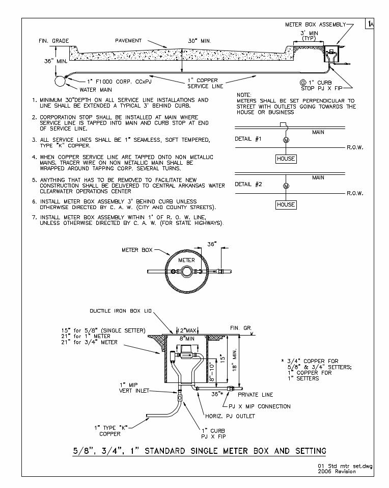
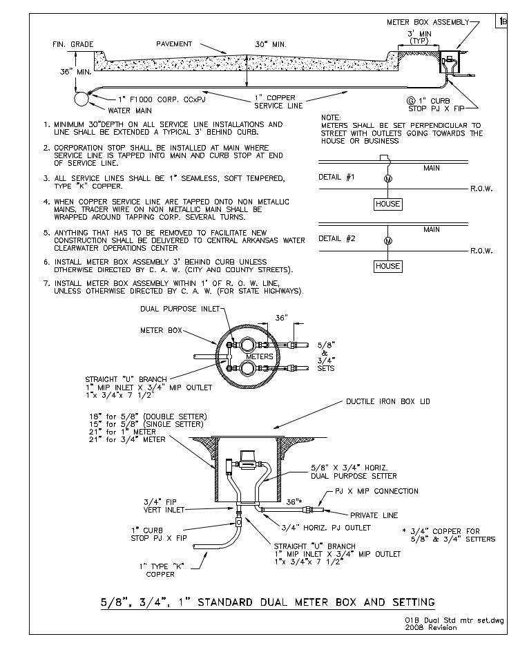

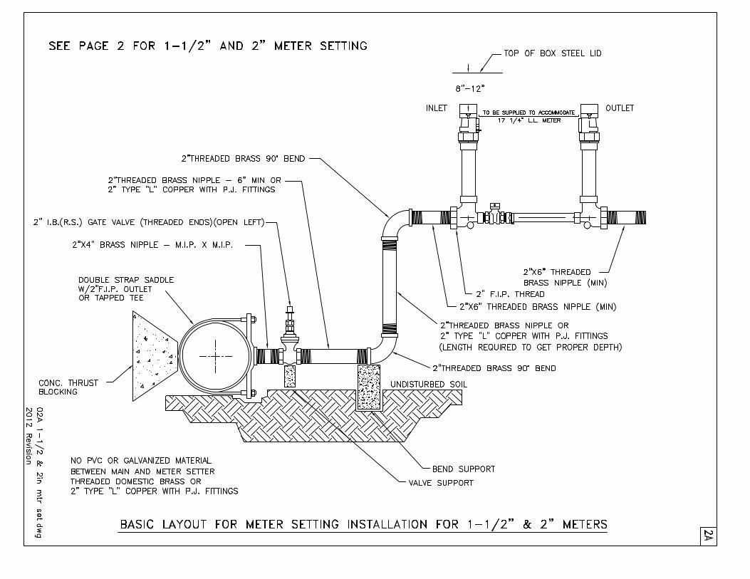
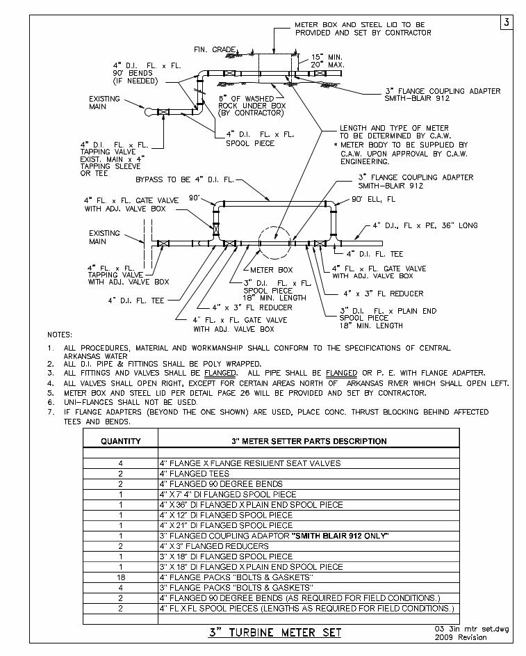
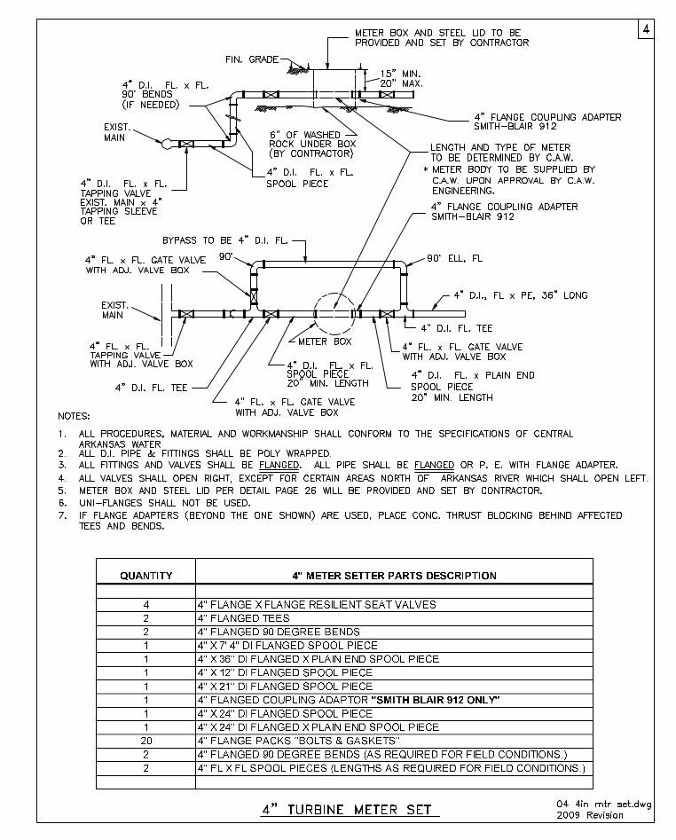
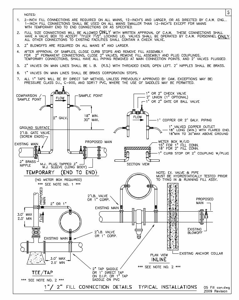
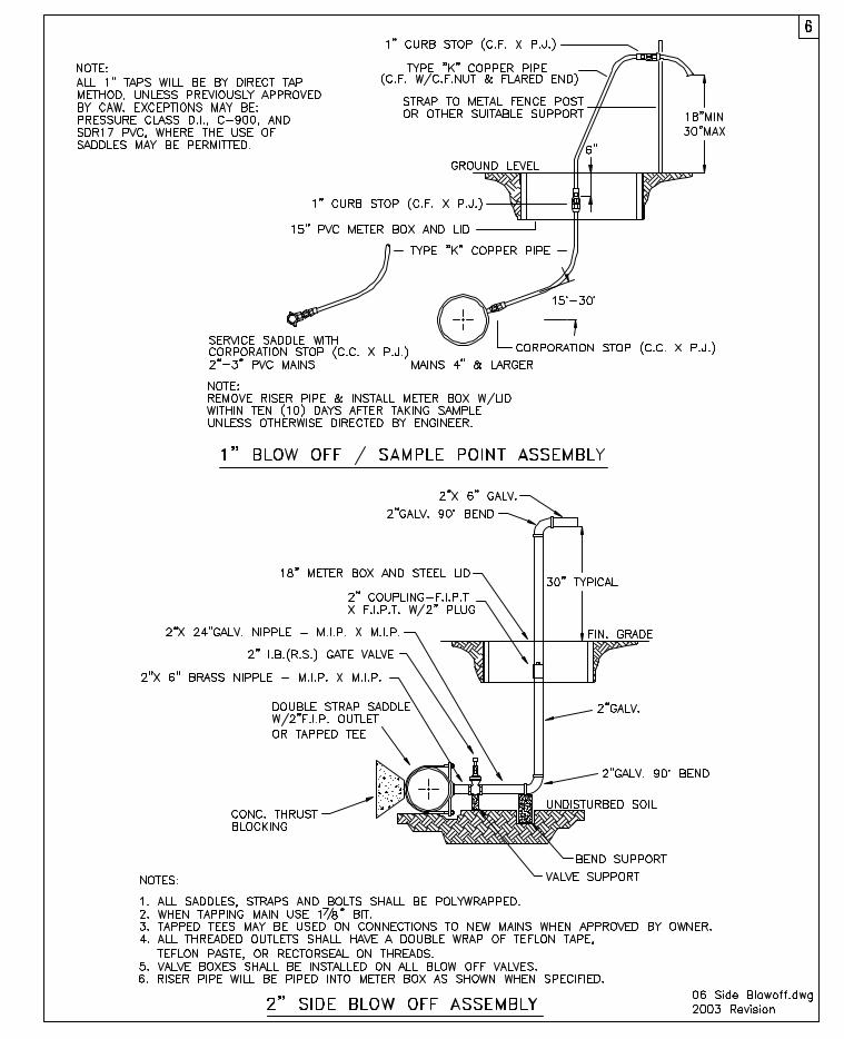
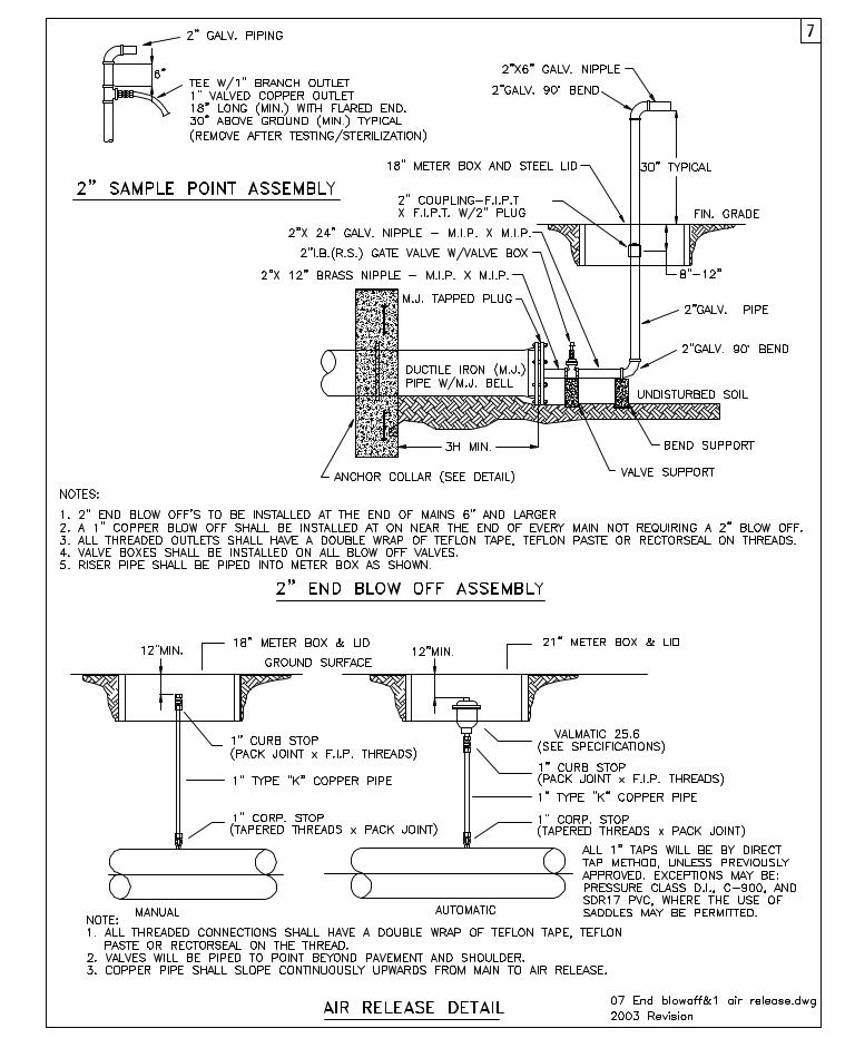
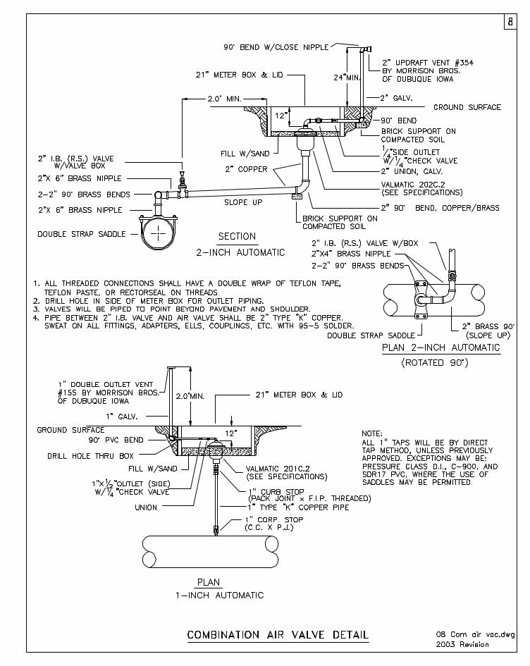
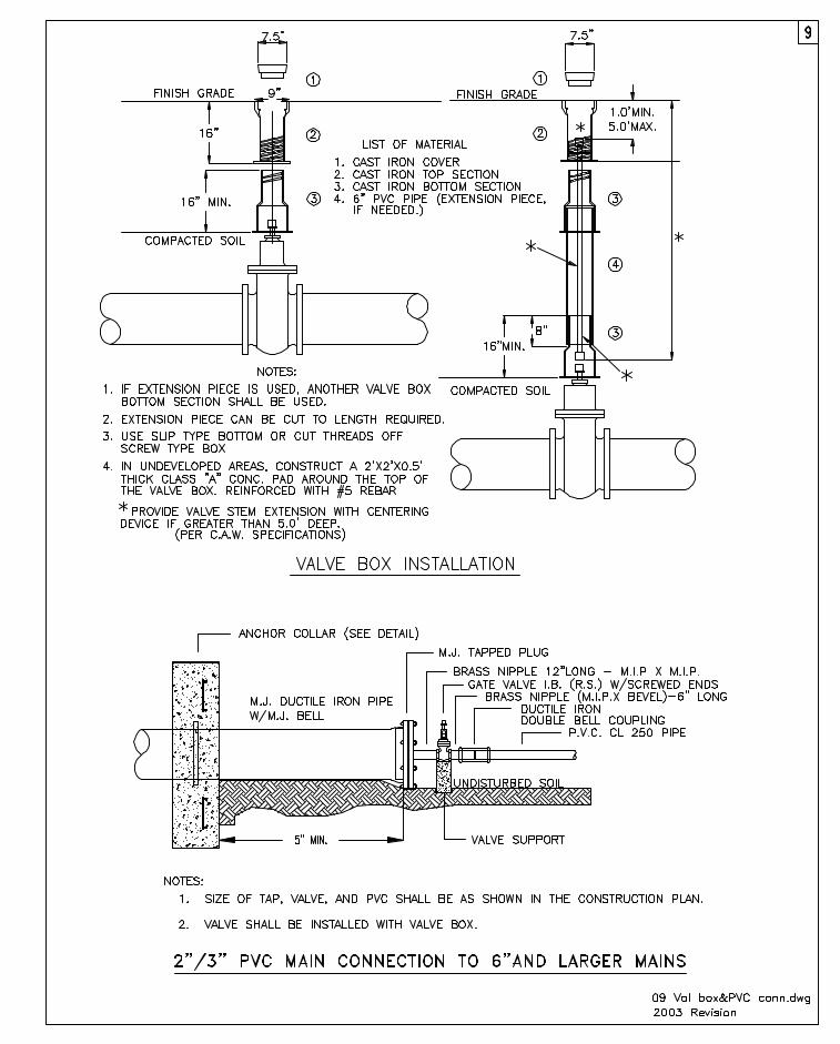
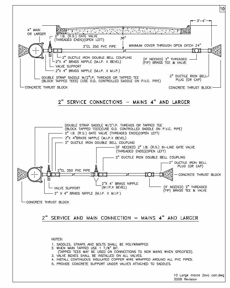
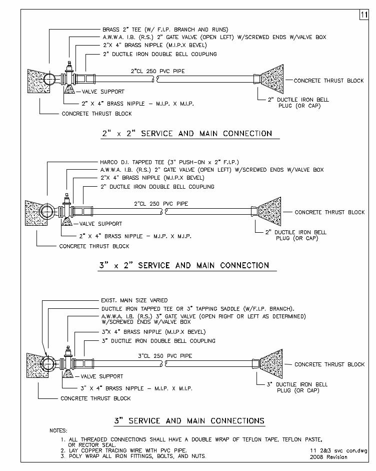
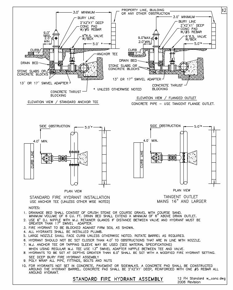
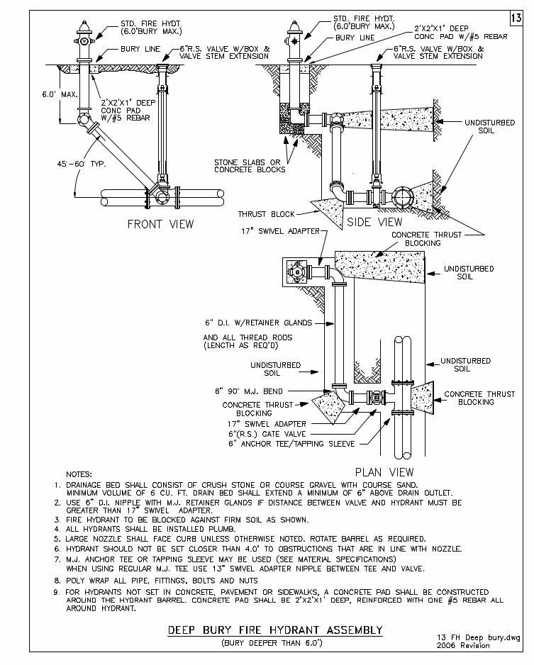
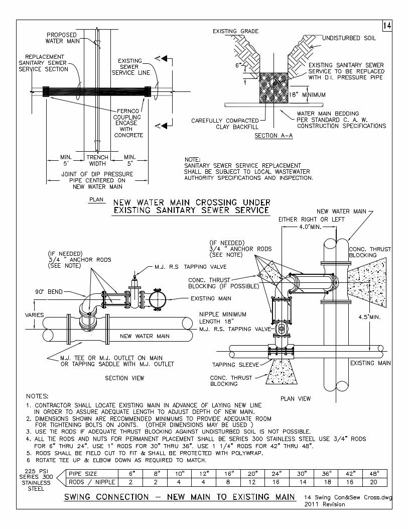
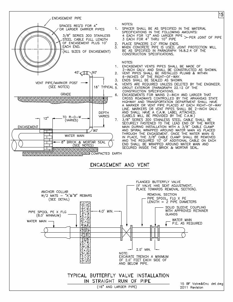
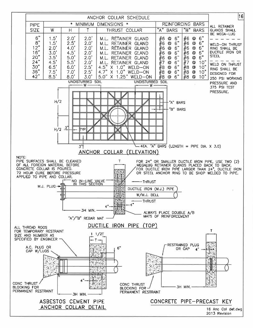
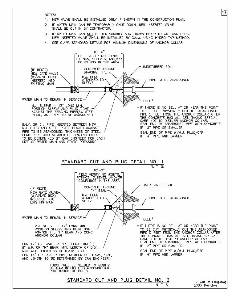
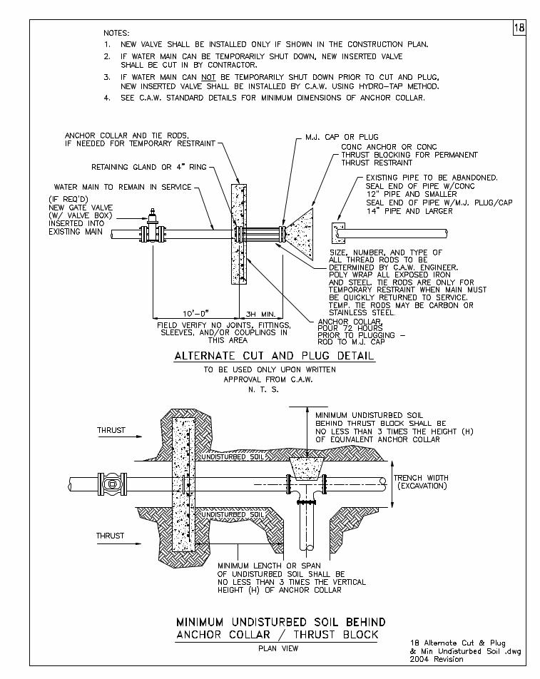
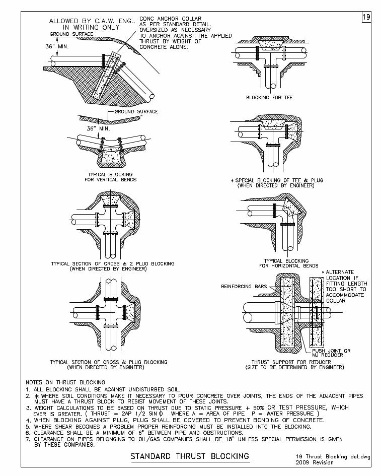
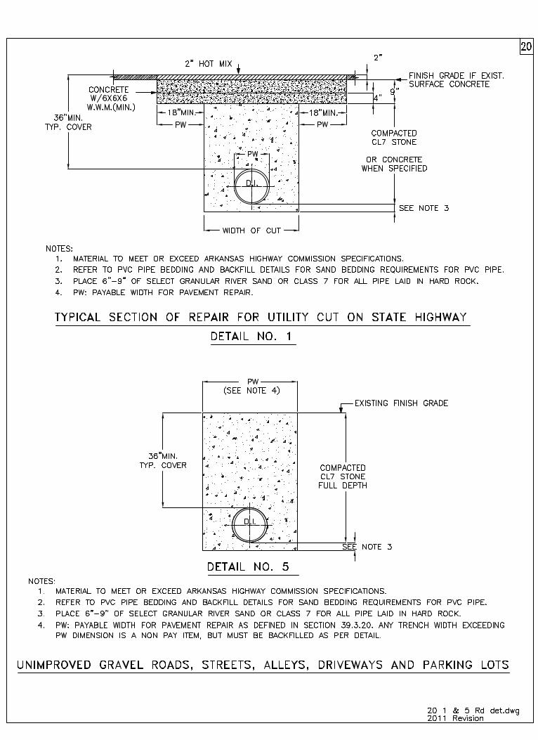
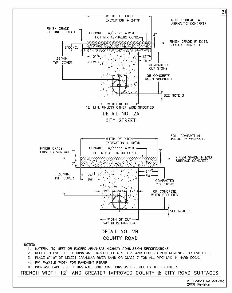
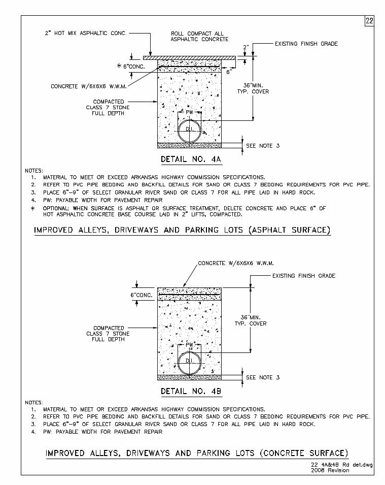
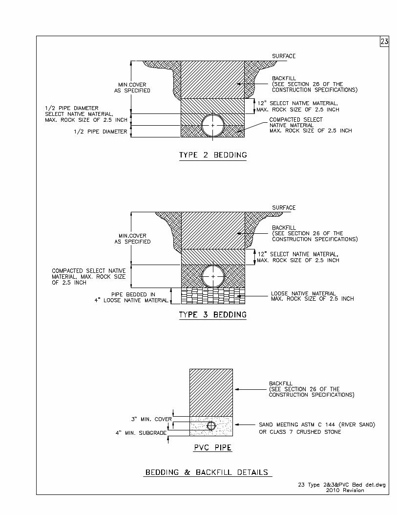
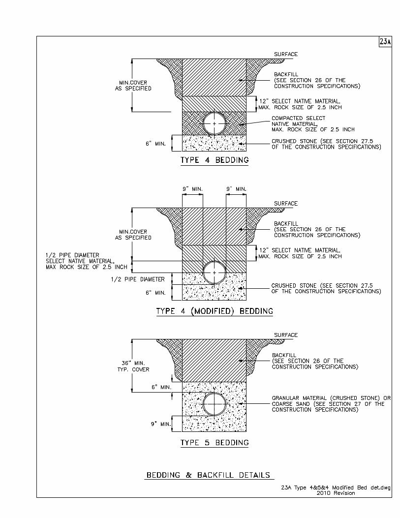
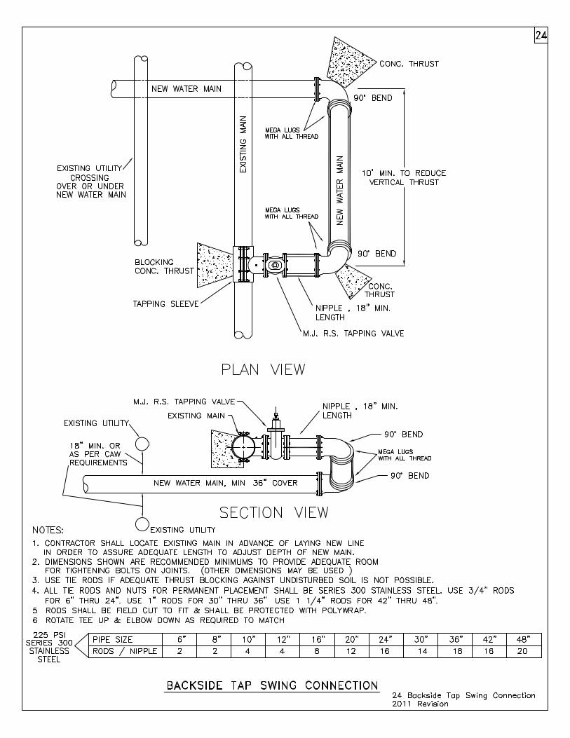
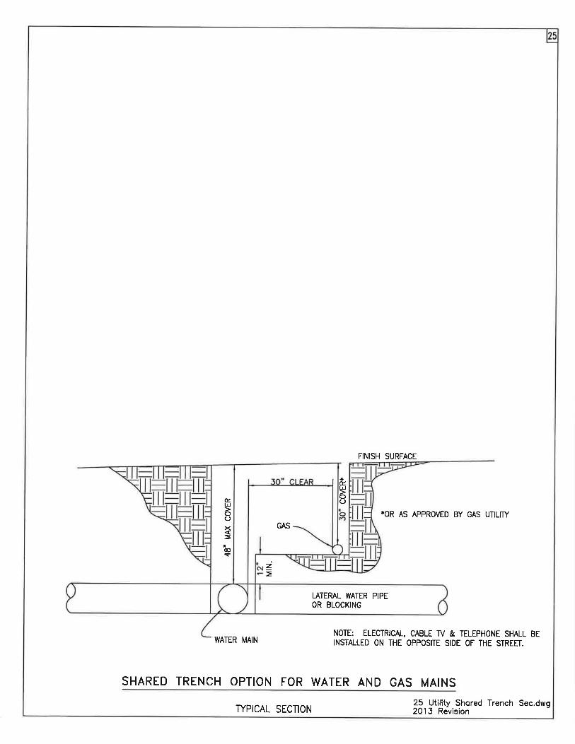
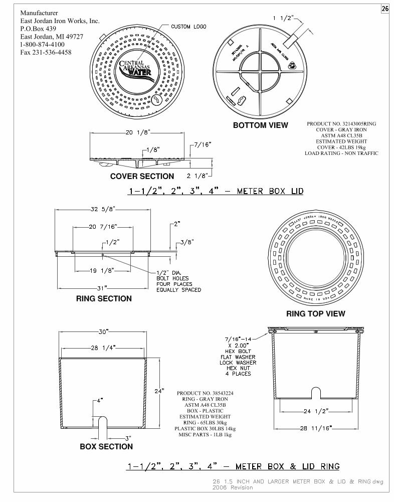
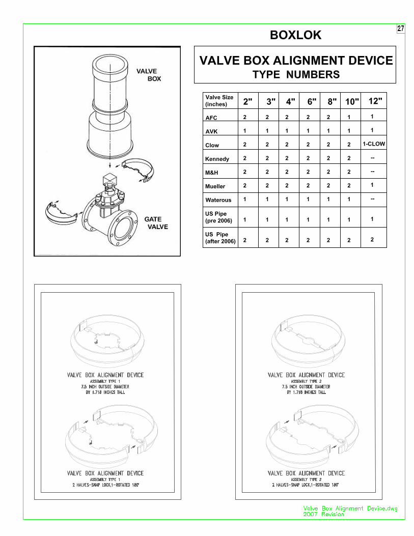
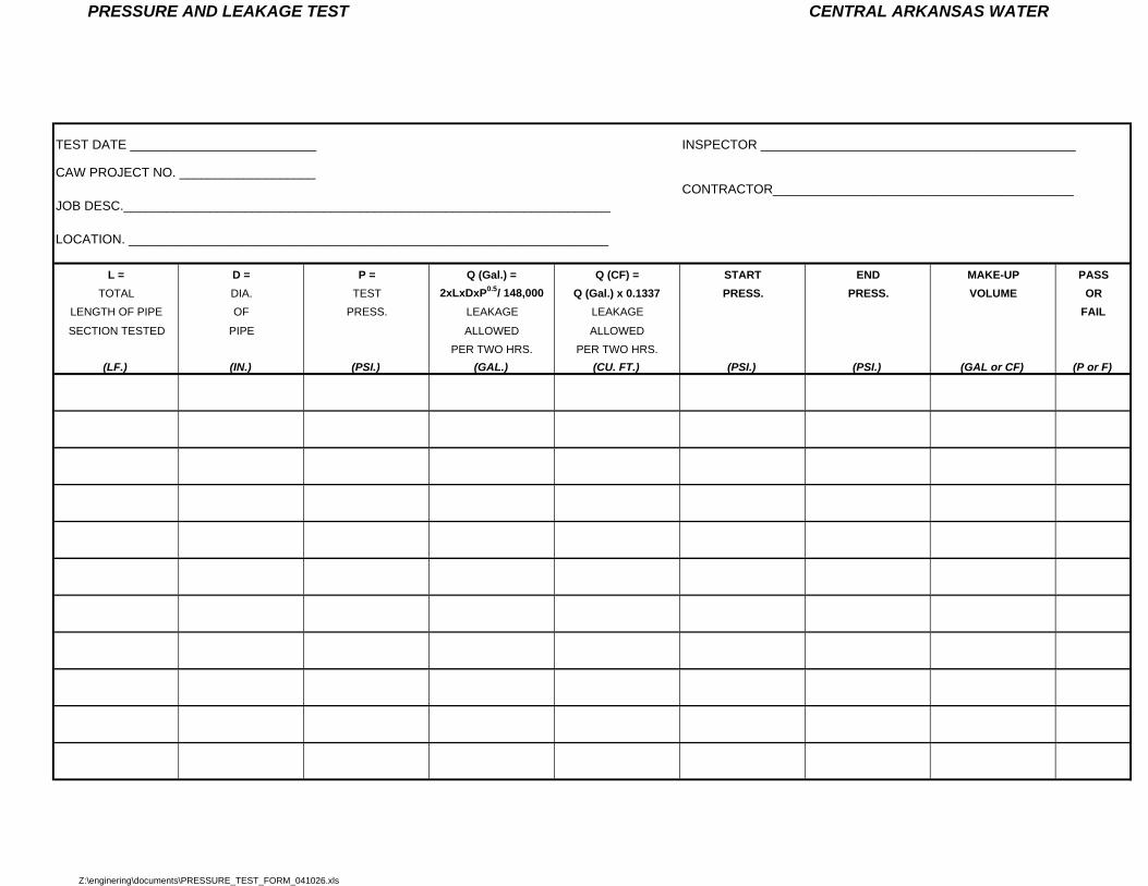
PRESSURE AND LEAKAGE TEST CENTRAL ARKANSAS WATER
TEST DATE __________________________ INSPECTOR ____________________________________________
CAW PROJECT NO. ___________________CONTRACTOR__________________________________________
JOB DESC.____________________________________________________________________
LOCATION. ___________________________________________________________________
L = D = P = Q (Gal.) = Q (CF) = START END MAKE-UP PASSTOTAL DIA. TEST 2xLxDxP0.5/ 148,000 Q (Gal.) x 0.1337 PRESS. PRESS. VOLUME OR
LENGTH OF PIPE OF PRESS. LEAKAGE LEAKAGE FAILSECTION TESTED PIPE ALLOWED ALLOWED
PER TWO HRS. PER TWO HRS.
(LF.) (IN.) (PSI.) (GAL.) (CU. FT.) (PSI.) (PSI.) (GAL or CF) (P or F)
Z:\enginering\documents\PRESSURE_TEST_FORM_041026.xls
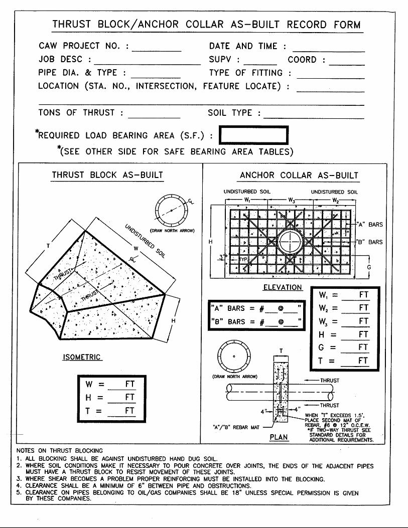
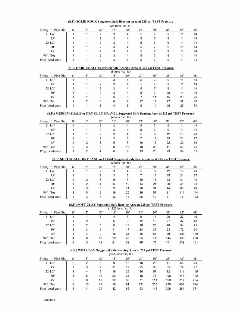
6” 8” 12” 16” 20” 24” 30” 36” 42” 48”
11 1/4° 1 1 2 3 4 5 7 9 11 1415° 1 1 2 3 4 5 7 9 11 14
22 1/2° 1 1 2 3 4 5 7 9 11 1430° 1 1 2 3 4 5 7 9 11 1445° 1 1 2 3 4 5 7 9 11 14
90° / Tee 1 1 2 3 4 5 7 9 11 14Plug (dead-end) 1 1 2 3 4 5 7 9 11 14
6” 8” 12” 16” 20” 24” 30” 36” 42” 48”
11 1/4° 1 1 2 3 4 5 7 9 11 1415° 1 1 2 3 4 5 7 9 11 14
22 1/2° 1 1 2 3 4 5 7 9 11 1430° 1 1 2 3 4 5 7 10 14 1845° 1 1 2 3 5 7 11 15 20 26
90° / Tee 1 2 3 6 9 12 19 27 37 48Plug (dead-end) 1 1 3 4 6 9 14 19 26 34
6” 8” 12” 16” 20” 24” 30” 36” 42” 48”
11 1/4° 1 1 2 3 4 5 7 9 11 1415° 1 1 2 3 4 5 7 9 11 14
22 1/2° 1 1 2 3 4 5 8 12 16 2030° 1 1 2 3 5 7 11 15 21 2745° 1 2 3 5 7 10 16 22 30 39
90° / Tee 2 3 5 8 13 18 29 41 56 72Plug (dead-end) 1 2 4 6 9 13 20 29 39 51
6” 8” 12” 16” 20” 24” 30” 36” 42” 48”
11 1/4° 1 1 2 3 4 5 8 12 16 2015° 1 1 2 3 5 7 11 15 21 27
22 1/2° 1 2 3 5 7 10 16 23 31 4030° 1 2 4 6 10 14 21 30 41 5345° 2 3 5 9 14 20 31 44 60 78
90° / Tee 3 5 9 16 25 36 57 81 111 144Plug (dead-end) 2 3 7 12 18 26 40 57 78 102
6” 8” 12” 16” 20” 24” 30” 36” 42” 48”
11 1/4° 1 1 3 4 7 9 14 20 27 4515° 1 2 3 6 9 12 19 27 37 48
22 1/2° 2 2 5 8 13 18 28 40 54 7130° 2 3 6 11 17 24 37 53 72 9445° 3 4 9 16 24 35 55 78 106 139
90° / Tee 4 8 16 29 45 64 100 144 196 256Plug (dead-end) 3 5 12 21 32 46 71 101 139 181
6” 8” 12” 16” 20” 24” 30” 36” 42” 48”
11 1/4° 2 2 5 9 13 18 29 41 56 7315° 2 3 7 11 17 25 38 55 74 97
22 1/2° 3 4 9 16 25 36 57 82 111 14530° 3 6 12 22 34 48 75 108 147 19245° 5 8 18 32 50 71 111 160 217 284
90° / Tee 9 15 33 59 91 131 205 295 401 524Plug (dead-end) 6 11 24 42 65 93 145 206 284 371
2/8/2008
(S.F.) WET CLAY Suggested Safe Bearing Area at 225 psi TEST Pressure
Fitting / Pipe Dia.(0.55 tons / sq. ft.)
(S.F.) SOFT SHALE, DRY SAND or LOAM Suggested Safe Bearing Area at 225 psi TEST Pressure
Fitting / Pipe Dia.
(S.F.) SOFT CLAY Suggested Safe Bearing Area at 225 psi TEST Pressure
Fitting / Pipe Dia.
(2 tons / sq. ft.)
(1.125 tons / sq. ft.)
(S.F.) SOLID ROCK Suggested Safe Bearing Area at 225 psi TEST Pressure
Fitting / Pipe Dia.(25 tons / sq. ft.)
(S.F.) HARD SHALE Suggested Safe Bearing Area at 225 psi TEST Pressure
Fitting / Pipe Dia.
(S.F.) MEDIUM SHALE or DRY CLAY GRAVEL Suggested Safe Bearing Area at 225 psi TEST Pressure
Fitting / Pipe Dia.
(6 tons / sq. ft.)
(4 tons / sq. ft.)