specifications for lidar - british columbia · specifications for lidar for the province of british...
TRANSCRIPT

Specifications for LiDAR for the
Province of British Columbia
Ministry of Forest, Lands and
Natural Resources Operations GeoBC
Version 3.0, March 2017
Victoria (BC), Canada

Owner: GeoBC
Version: 3.0
Issue Date: March. 2017
Title: Specifications for LiDAR for the
Province of British Columbia
2
Table of Contents
1.0 RECORD OF AMENDMENTS ........................................................................................................................................................ 4
2.0 INTRODUCTION .......................................................................................................................................................................... 5
3.0 PURPOSE AND SCOPE ................................................................................................................................................................. 5
4.0 LiDAR BACKGROUND .................................................................................................................................................................. 5
5.0 ACQUISITION AND QUALITY ASSURANCE ................................................................................................................................... 8
5.1 LiDAR Error Budget ......................................................................................................................................................................... 8 5.1.1 Systematic Errors .................................................................................................................................................................... 9 5.1.2 Random Errors ...................................................................................................................................................................... 10
5.2 Calibration and Data Adjustments ............................................................................................................................................... 10 5.2.1 System Calibration ................................................................................................................................................................ 10 5.2.2 Data Adjustments ................................................................................................................................................................. 11 5.2.3 Ground Control Points .......................................................................................................................................................... 11
5.3 LiDAR Acquisition Guidelines ........................................................................................................................................................ 12
5.4 Spatial Distribution and Area Coverage ....................................................................................................................................... 13 5.4.1 Data Spatial Regularity .......................................................................................................................................................... 13 5.4.2 Area Coverage ....................................................................................................................................................................... 13 5.4.3 Data Voids ............................................................................................................................................................................. 14
6.0 DATA PROCESSING AND FORMATTING .................................................................................................................................... 14
6.1 Scope of Collection ....................................................................................................................................................................... 14
6.2 Data Format ................................................................................................................................................................................. 14
6.3 Point Cloud Classification ............................................................................................................................................................. 14
6.4 Tiling ............................................................................................................................................................................................. 17
6.5 Data Handling and Shipping ......................................................................................................................................................... 17
7.0 QUALITY CONTROL AND ACCURACY REPORTING...................................................................................................................... 18
7.1 Absolute Vertical Accuracy: Methodology and Requirements ..................................................................................................... 18
7.2 Point Density and Point Spacing ................................................................................................................................................... 19 7.2.1 Nominal Point Density .......................................................................................................................................................... 19 7.2.2 Nominal Point Spacing .......................................................................................................................................................... 19
7.3 Relative Accuracy: Methodology and Requirements .................................................................................................................... 19 7.3.1 Intraswath accuracy .............................................................................................................................................................. 19 7.3.2 Interswath accuracy .............................................................................................................................................................. 21
7.4 Absolute Horizontal Accuracy ...................................................................................................................................................... 22 7.4.1 Absolute Horizontal Accuracy Methodology ........................................................................................................................ 22 7.4.2 A-Priori LiDAR horizontal accuracy estimation ..................................................................................................................... 24

Owner: GeoBC
Version: 3.0
Issue Date: March. 2017
Title: Specifications for LiDAR for the
Province of British Columbia
3
7.5 LiDAR Classification Accuracy and Errors ..................................................................................................................................... 25
8.0 REQUIREMENTS FOR DELIVERABLES ......................................................................................................................................... 26
8.1 User Requirements Checklist for Airborne LiDAR ......................................................................................................................... 26
8.2 Mission Planning Report .............................................................................................................................................................. 28
8.3 Operational Parameters Report ................................................................................................................................................... 28
8.4 Ground Control and Base Station Reports .................................................................................................................................... 29
8.5 Calibration and Adjustment Report .............................................................................................................................................. 30
8.6 Survey Reports and Flight Logs..................................................................................................................................................... 30
8.7 Quality Assurance Procedures and Reports .................................................................................................................................. 31
8.8 Production and Processing Report ............................................................................................................................................... 31
8.9 Quality Control Procedures and Reports ...................................................................................................................................... 32
9.0 METADATA FORMAT AND CONTENT ........................................................................................................................................ 32
10.0 REFERENCES ........................................................................................................................................................................... 33
APPENDIX A: ACCURACY REPORTING ............................................................................................................................................. 35
APPENDIX B: FILES NAMING CONVENTIONS .................................................................................................................................. 37
LIST OF ACRONYMS ........................................................................................................................................................................ 38
GLOSSARY OF TERMS ..................................................................................................................................................................... 39
LIST OF TABLES ............................................................................................................................................................................... 47

Owner: GeoBC
Version: 3.0
Issue Date: March. 2017
Title: Specifications for LiDAR for the
Province of British Columbia
4
1.0 RECORD OF AMENDMENTS
Version
No.
Revision
made by Page#
Revision
Description Approved by Signature Date
1.0
2.0
3.0
Harald Steiner
D. Garnham
Isabelle Paquin
Brett Edwards
James Thompson
Robert Prins
1-36
1-40
1-42
Re-write
Major revision of 1.0
Revision to align
with GeoBC 2016 DEM
specifications
Harald Steiner, Geom Eng
Harald Steiner, PEng
Harald Steiner, PEng
31-Mar-2013
21-Mar-2014
04-Oct-2016

Owner: GeoBC
Version: 3.0
Issue Date: March. 2017
Title: Specifications for LiDAR for the
Province of British Columbia
5
2.0 INTRODUCTION
These specifications were compiled to provide geospatial data suppliers with some
common standard and clear requirements for the production of LiDAR datasets, with
the objective of obtaining consistent, high-quality LiDAR products deliverables
to the British Columbia Provincial Government.
These LiDAR specifications supersede all previous LiDAR specifications. One
should note that this document is a living one, and it will be updated and
maintained through the ongoing feedback from industry experts and advances in the
LiDAR technology processing methodologies.
The term “Branch”, when used herein, shall mean GeoBC of the Ministry of Forests,
Lands and Natural Resource Operations in the Province of British Columbia.
The Branch shall be the final authority on acceptance or rejection of submitted
LiDAR data. All LiDAR material, data and products delivered to the Branch shall
meet or exceed the following specifications.
For the purpose of these specifications, the word “shall” indicates a mandatory
requirement and “should” indicates a desirable requirement.
3.0 PURPOSE AND SCOPE
This document has been created to outline clear specifications for the support of
Quality Assurance (QA) and Quality Control (QC) of LiDAR data and subsystems.
This document is not meant to be prescriptive but does describe desired results
and tolerances. More precisely, the purpose of these specifications are to:
Focus on results, not on how a system should be calibrated.
Provide minimum standards regarding accuracy, deliverables, and quality.
Ensure proper and consistent deliverables.
Ensure a high level of data integrity.
4.0 LiDAR BACKGROUND
Mobile LiDAR acquisition modes are of three main types:
Airborne LiDAR scanning (ALS): scanning with a LiDAR scanner mounted to a
platform in an aircraft (rotor or fixed-wing aircraft).
Mobile LiDAR scanning (MLS): scanning from a ground-based mobile vehicle.
Unmanned LiDAR scanning (ULS): scanner mounted on an Unmanned Aerial
Vehicle (UAV).
The specifications detailed in this document are applicable primarily to ALS.

Owner: GeoBC
Version: 3.0
Issue Date: March. 2017
Title: Specifications for LiDAR for the
Province of British Columbia
6
A Light Detection and Ranging (LiDAR) system consists of the following
components:
An inertial navigational measurement unit (IMU) continuously recording the
aircraft’s orientation (attitude vectors).
A high-precision Global Positioning System (GPS) unit recording the three-
dimensional position of the aircraft.
A computer interface managing communication between devices and data
storage during acquisition.
The system also necessitates that a GPS base station is operating simultaneously
to correct differentially and improve the precision of the collected airborne GPS
data. That base station is typically installed at a known location on the ground
and in the vicinity (within 30-50 kilometres) of the aircraft.
LiDAR systems are a fast, accurate, and cost-effective technology for direct
acquisition of small or large-scale, dense 3D-point data. LiDAR data is
visualised as a point cloud collected by measuring the time between the emission
of a laser pulse and the return of the reflected energy to the laser receiver.
The time between transmission and receiving of a laser return is converted to a
distance and integrated with the platform position and orientation to obtain
real-world coordinates. Those world coordinates are transformed into projected
map coordinates. After georeferencing the data, the LiDAR points and associated
metadata are exported into manageable data files, suitable for conversion to a
format such as LAS using the appropriate ASPRS LAS standard.
LiDAR data consist of irregularly spaced points and attribute information that
includes position, assigned colour, time stamp and other additional records about
the laser return. This process requires a different data container when compared
to regular digital imagery raster data. Also, the LAS format can host additional
information such as spectral encoded RGB colour information of digital imagery.
There are two types of LiDAR acquisition; these are differentiated by how
backscattered laser energy is quantified and recorded by the sensor. With full-
waveform LiDAR (e.g., ASPRS LAS version 1.4 [2]), the energy reflected back to the
sensor is logged as a nearly continuous signal. With discrete-return or small-
footprint LiDAR (e.g., ASPRS LAS version 1.2 [1]), the energy reflected is
recorded at precisely referenced points in space (x, y, z coordinates) and time,
at amplitude intervals. The energy amplitude relating to each return is known as
intensity.
Unless specified otherwise in the contract, LiDAR data shall be delivered in LAS
1.2 format, following the “LAS Specification Version 1.2 (2008)” requirements.
Other LiDAR format, such as LAS 1.4, might be used if allowed in the User
Requirements Checklist, in which case the requirements of the “LAS Specification
Version 1.4–R13 (2013)” shall be followed. However, the specifications described
in this document do not detail deliverables on full-waveform LiDAR.

Owner: GeoBC
Version: 3.0
Issue Date: March. 2017
Title: Specifications for LiDAR for the
Province of British Columbia
7

Owner: GeoBC
Version: 3.0
Issue Date: March. 2017
Title: Specifications for LiDAR for the
Province of British Columbia
8
Before performing data analysis towards generating any deliverable, the integrity
of the dataset must be validated. This validation includes verifying that the
absolute and relative accuracy of the point cloud is as expected. The
contributing factors and associated processes will be discussed in detail later
in this document.
After having validated the data integrity, the data goes through a series of
steps that vary between providers but are similar in their goals. These steps
take the data from calibrated, unclassified data to the desired deliverable.
There is considerable room for ambiguity in specifying deliverables, so it is
essential to be as explicit as possible about the final deliverable requirements
before data collection.
LiDAR datasets are usually large, and file sizes will vary according to point
density, information stored within each file, and total area covered per file.
A LAS 1.2 file covering 1 Km², with an average total density of <1 point per
square metre can be approximately 60MB (uncompressed) depending on format type
and number of returns. Typically, LiDAR datasets are broken down into file sizes
that can be easily manipulated on a high-end processing workstation using
specialised tools.
One of the inherent problems with LiDAR data is that individual LiDAR returns
cannot be directly associated with a feature, this means that trying to analyse
unclassified LiDAR data points will yield little useful information. It is only
by analysing groups of LiDAR points together that context is achieved, and
individual points can be grouped into categories according to recognisable
features. The easiest way to do this is to group the LiDAR data into distinct
feature classes based on the ASPRS Standard LiDAR point class structure. It is
also important to note that LiDAR data providers will often have widely varying
standards and definitions with regards to how LiDAR classes are derived. It is in
the best interest of the Branch to provide a common set of standards to ensure
uniform data quality and a standardised data format.
5.0 ACQUISITION AND QUALITY ASSURANCE
Quality Assurance (QA) is a set of activities that ensure quality in the
processes by which products are developed. In particular, the measures that are
taken to ensure the quality of the source data, before and during the acquisition
of the data.
5.1 LiDAR Error Budget
LiDAR errors are categorised into random and systematic components. Systematic
errors in the data can be reconciled and possibly reduced or eliminated through
calibration and adjustment, whereas random errors cannot. All LiDAR system
malfunctions shall be recorded, and the Branch shall be notified. A malfunction
is defined as a failure anywhere in the acquisition platform units that causes an
interruption to the normal operation of the system.
Owner: GeoBC
Version: 3.0
Issue Date: March. 2017
Title: Specifications for LiDAR for the
Province of British Columbia
9
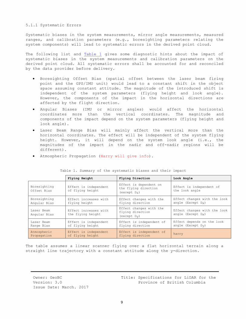
5.1.1 Systematic Errors
Systematic biases in the system measurements, mirror angle measurements, measured
ranges, and calibration parameters (e.g., boresighting parameters relating the
system components) will lead to systematic errors in the derived point cloud.
The following list and Table 1 gives some diagnostic hints about the impact of
systematic biases in the system measurements and calibration parameters on the
derived point cloud. All systematic errors shall be accounted for and reconciled
by the data provider before delivery.
Boresighting Offset Bias (spatial offset between the laser beam firing
point and the GPS/IMU unit) would lead to a constant shift in the object
space assuming constant attitude. The magnitude of the introduced shift is
independent of the system parameters (flying height and look angle).
However, the components of the impact in the horizontal directions are
affected by the flight direction.
Angular Biases (IMU or mirror angles) would affect the horizontal
coordinates more than the vertical coordinates. The magnitude and
components of the impact depend on the system parameters (flying height and
look angle).
Laser Beam Range Bias will mainly affect the vertical more than the
horizontal coordinates. The effect will be independent of the system flying
height. However, it will depend on the system look angle (i.e., the
magnitudes of the impact in the nadir and off-nadir regions will be
different).
Atmospheric Propagation (Harry will give info).
Table 1. Summary of the systematic biases and their impact
Flying Height Flying Direction Look Angle
Boresighting
Offset Bias
Effect is independent
of flying height
Effect is dependent on
the flying direction
(except Dz)
Effect is independent of
the look angle
Boresighting
Angular Bias
Effect increases with
flying height
Effect changes with the
flying direction
Effect changes with the look
angle (Except Dx)
Laser Beam
Angular Bias
Effect increases with
the flying height
Effect changes with the
flying direction
(except Dy)
Effect changes with the look
angle (Except Dx)
Laser Beam
Range Bias
Effect is independent
of flying height
Effect is independent of
flying direction
Effect depends on the look
angle (Except Dy)
Atmospheric
Propagation
Effect is independent
of flying height
Effect is independent of
flying direction harry
The table assumes a linear scanner flying over a flat horizontal terrain along a
straight line trajectory with a constant attitude along the y-direction.

Owner: GeoBC
Version: 3.0
Issue Date: March. 2017
Title: Specifications for LiDAR for the
Province of British Columbia
10
5.1.2 Random Errors
Random errors comprise the remaining errors after all systematic errors have been
accounted for and corrected. Random errors might occur in the dataset as random
noise or false-positive LiDAR returns that will be apparent when points are very
high or much lower than the collected data. All random error points shall be
classified using the “Withheld Point” class code (Section 6.3) before processing
the deliverables because they can significantly skew statistical data and
interfere with certain classification algorithms. Care should be taken not to
remove legitimate LiDAR returns accidentally when using automatic classification
routines for extracting erroneous points.
5.2 Calibration and Data Adjustments
Sensor calibration and maintenance shall be performed to ensure proper function
of the LiDAR system. Any requests by the Branch to submit evidence that the
sensor system was calibrated before the project began to identify and correct
systematic errors, shall be met.
5.2.1 System Calibration
Calibration, when applied to a LiDAR acquisition system, refers to the process of
identifying and correcting for systematic errors in hardware, software and/or
procedures. Sensors shall be calibrated for geometry and intensity.
Instrument calibration: Factory calibration includes radiometric and
geometric calibration unique to each manufacturer’s hardware, and tuned to
meet the performance specifications for the model being calibrated.
Instrument calibration can only be assessed and corrected by the factory.
Data calibration (boresight calibration): The lever arm calibration
determines the IMU to GPS antenna phase centre and sensor to IMU (rGPS and
rIMU in Figure 1) offset vectors components relative to the antenna phase
centre. The offset vectors components shall be re-determined each time the
sensor or aircraft GPS antenna is moved or repositioned in any way.
Figure 1. Relationships between the lever arms of an airborne LiDAR platform.
GPS IMU (Platform Reference Origin)
Ya
Xa
Sensor Reference System
Za
IMU-to-Sensor
zs
xs, xsc
ys
rGPS
rIMU

Owner: GeoBC
Version: 3.0
Issue Date: March. 2017
Title: Specifications for LiDAR for the
Province of British Columbia
11
Because normal aircraft operations can induce slight variations in component
mounting, boresight calibration shall be performed at least twice during each
project, at the beginning and the end of a project. This verification allows
determining the corrections to the roll, pitch, yaw, and scale calibration
parameters, even if the sensor or antenna were not moved. If any modifications
are made to any of the calibration parameters (including sensors), the supplier
shall provide a post, re-calibration control report along with the pre-
calibration control report.
Calibration done in the field should include different planes, not only flat
surfaces. For examples, targets could be positioned on an inclined, non-vegetated
and smooth surfaces, like a road going uphill and downhill, in addition to flat
surfaces.
Report of calibration containing the values used, including all factory settings
as well as user settings, shall be delivered. Additional calibration parameters
may be requested by the Branch.
5.2.2 Data Adjustments
After having reconciled the systematic errors, the dataset may still contain
artefacts related to flight-line overlap or adjustments to a particular local
datum, geoid or other changes using least squares adjustment tools and
transformations.
A high-level overview of the steps performed to arrive at final positioning
should be provided with the delivery, with an output report describing the
methodology and software used, and including all results.
5.2.3 Ground Control Points
All aerial LiDAR survey missions are required to be supported by a network of GPS
base stations. This is essential for ensuring the absolute accuracy of the LiDAR
point cloud. A GPS network that fulfils the minimum accuracy requirements shall
include:
At least one fixed control point (e.g., high precision survey monuments,
active control stations, etc.). Additional fixed control points are
desirable.
At least one GPS network point used for processing flight trajectories.
This may also be used as a vertical checkpoint for the LiDAR dataset.
At least one additional GPS point must be established and observed
simultaneously in order to close the loop, creating two independent
baselines. This shall be used as a vertical checkpoint for the LiDAR
dataset.
Baselines should not exceed 30km in length.

Owner: GeoBC
Version: 3.0
Issue Date: March. 2017
Title: Specifications for LiDAR for the
Province of British Columbia
12
The amount of GPS base stations will depend largely on the size and location of
the project site. It is recommended that an additional LiDAR checkpoint be
established that is tied into the network. This is crucial in situations where
the GPS station that is to be used for processing trajectories is not within the
project site and therefore is not available for use as a LiDAR checkpoint. It is
encouraged that additional control is collected to create a robust ground control
network, ensuring the geometric quality of the network and the point cloud.
Unless specified otherwise in the contract, a minimum of ten control points
distributed over the entire area shall be used, and should include inclined
planes and cover different aspects, not only flat surfaces.
The distance between a GPS base station used in processing trajectories and the
aircraft should not exceed 50km in open terrain and 30km in mountainous terrain.
This assures optimal processing of trajectories and gives confidence to the
geometric quality of the point cloud. If longer baselines are observed due to
mitigating circumstances, it may be required that final trajectories are
processed once precise ephemerides are available. For GPS survey best practices,
please refer to the “Specifications and Guidelines for Control Surveys Using GPS
Technology (2010)”[14].
5.3 LiDAR Acquisition Guidelines
Flight planning and hardware specifics are left to the data provider, as long as
they meet the requirements and standards, and complete all relevant reports.
However, all pre-acquisition plans shall be completed and submitted before
acquisition start. The proposed flight plan covering the geographic area to be
surveyed shall be defined as a set of flight lines declared with planned flight
line overlap and include the expected buffer zone (Section 5.4). Plans shall be
provided as MicroStation V8 DGN files and as ESRI SHP files.
Flying height is defined as the aircraft altitude above ground level, at nadir
position, and is a function of the area to be covered in a single pass and
minimum flying height safety protocols. In some cases, where there are supporting
sensor requirements such as aerial photography for producing rectified imagery,
more than one pass may be required to capture data within the desired parameters.
Keeping a constant flying height above ground reduces systematic errors that are
difficult to detect such as laser range scale errors.
The required overlap between flight lines shall be planned at 30% minimum in open
urban areas and 50% minimum in vegetated areas. The bank angle must be kept at
15° maximum (absolute maximum 20°) unless the safety of the aircraft is affected.
In addition to the flight plans and general acquisition information, the system
specifications and operation parameters shall be documented and also submitted to
the Branch (Section 8.3).

Owner: GeoBC
Version: 3.0
Issue Date: March. 2017
Title: Specifications for LiDAR for the
Province of British Columbia
13
5.4 Spatial Distribution and Area Coverage
The projected collection area, i.e., the Area of Interest (AOI), shall be
buffered by a minimum of one-half swath outside of the AOI borders to create a
Buffered Project Area (BPA). Ideally, a flight line centre should be positioned
on the AOI border before drawing additional flight lines. Data collection is
obligatory for the full extent of the BPA, and all products shall be generated to
the full extent of the BPA. However, data and products in the buffer area (the
area between the AOI and the BPA) will not be tested for any of the quality
requirement. Control points used for QA may be located in the buffer;
verification points used for QC shall not be found in the buffered area.
5.4.1 Data Spatial Regularity
The spatial distribution of geometrically usable points should be uniform and
regular. Although LiDAR instruments do not typically produce regularly gridded
points, collections shall be planned and executed to generate a first return
point cloud approaching a regular lattice of points.
The regularity of the point pattern and density throughout the dataset should be
assessed by using a method similar to the following steps, using first return
points:
Generate a density grid from the ground data with cell sizes equal to twice
the required LiDAR Nominal Point Spacing (NPS) and a radius equal to the
required NPS (Section 7.2.2).
Ensure that 90% of the cells in the grid contain at least one usable LiDAR
point, using single swaths, with only the first return points located
within the geometrically usable centre part (typically 95%) of each swath.
Exclude acceptable data voids (Section 5.4.3).
5.4.2 Area Coverage
A coverage check shall be performed by loading the cumulatively acquired LiDAR
dataset, along with the BPA, into one of the many software packages available for
such projects. The data shall be examined to check the area’s coverage, gaps
between flight lines and holes or other abnormalities caused by sensor errors.
The coverage check shall be done daily in the field and again before the plane
leaves the surveyed area to ensure all flight lines are covered, including
adequate swath overlap. That way, if a problem is found, a reflight can be
completed without the cost of remobilizing the plane.

Owner: GeoBC
Version: 3.0
Issue Date: March. 2017
Title: Specifications for LiDAR for the
Province of British Columbia
14
5.4.3 Data Voids
Data voids covering areas larger than 4 x NPS2 for single swaths, first returns
points, are not acceptable, except where caused by:
Water bodies and other areas of little Near Infra-Red (NIR) reflectivity
such as dark tar-asphalted surfaces.
Object shadowing (e.g., buildings, towers, vertical cliffs) unless
previously stipulated in the project contract that all shadowed areas must
be captured with subsequent flight lines.
6.0 DATA PROCESSING AND FORMATTING
The next steps in the process after acquisition and QA are classifying and tiling
the LiDAR points. The main delivery of LiDAR data is the original point cloud, in
LAS format. After completing QC on the final data (Section 7.0), the other
required deliverables and reports can be compiled (Section 8.0)
6.1 Scope of Collection
All collected swaths, including calibration swaths and cross-ties and all
collected returns within each swath, shall be delivered as part of the final
deliverables. No original points are to be deleted from the LAS files. Exceptions
to this rule are the extra data outside of the AOI (such as aircraft turns,
transit between the collection area and airport, and transit between fill-in
areas). These points may be permanently removed from the data delivered as are
the swaths that are being completely discarded by the vendor and reflown.
6.2 Data Format
All processing will be carried out with the understanding that all point
deliverables are required to be fully compliant with the appropriate ASPRS LAS
Specification. Unless specified otherwise in the project checklist, LiDAR data
shall be delivered in LAS 1.2 (ASPRS, 2008)[1]. The intensity value is the numeral
representation of the pulse return magnitude and shall always be included for
each discrete return. Intensity shall be normalised to a 16-bit, unsigned value.
6.3 Point Cloud Classification
Table 2 is modified from the “ASPRS Standard LiDAR Point Classes” and list the
basic Class Codes that shall be used for LiDAR classification. Those codes are
part of the Project checklist and can be customised to add other codes, as
needed.
Outliers, noise points, geometrically unreliable points near the extreme edge of
the swath, and other points the vendor deems unusable shall be identified using
Class Code 7 (Withheld Point). This classification applies primarily to points
that are identified during pre-processing or through automated post-processing
routines or to noise points subsequently identified during manual classification

Owner: GeoBC
Version: 3.0
Issue Date: March. 2017
Title: Specifications for LiDAR for the
Province of British Columbia
15
or QA/QC.

Owner: GeoBC
Version: 3.0
Issue Date: March. 2017
Title: Specifications for LiDAR for the
Province of British Columbia
16
Table 2. Classification Codes and Description
Class Code Abbr. Description
0 RAW Created, never classified (raw data)
1 DEF Default class, unclassified
2 GRD Ground
3 LVG Low Vegetation (< 0.3 metre)
4 MVG Medium Vegetation (0.3-1 metre)
5 HVG High Vegetation (> 1 metre)
6 BLD Building
7 WHD Withheld Point / Noise
8 MKP Model Key Point
9 WTR Water Body
10 RR Railroad
11 PRD Paved Road
12 -- Reserved (Overlap)
13 UPR Unpaved Road
14 PKG Parking
15 DRW Driveway
16 BDG Bridge Deck
17 MSC All Miscellaneous
18 MSP Miscellaneous Permanent
19 MST Miscellaneous Temporary
20 to 31 -- Other Project specific codes
If overlap points are required to be differentiated by the data producer, they
must be identified using a method that does not interfere with their
classification. The technique used to identify overlap must be clearly described
in the project reports.
Further instructions regarding classification:
ALL points not classified as Withheld Point shall be classified.
No points in the LAS deliverable shall remain in Class Code 0 or 1.
Depending on the project requirements, the Class Code 2 (Ground) may
include other flat surfaces (e.g., Roads, Parking lots, Bridge decks)
instead of classifying them separately, in which case it would be indicated
in the User Requirements Checklist.
If only Ground and non-ground classes are needed, use the Class Code 17
(All Miscellaneous) to classify non-ground points that are not classified
as Withheld Point.
The Class Code 18 (Miscellaneous Permanent) include all man-made objects or
structures that are not mobile and do not belong in any other Class Code
(e.g., electrical or telecommunication structures, billboards, fences,

Owner: GeoBC
Version: 3.0
Issue Date: March. 2017
Title: Specifications for LiDAR for the
Province of British Columbia
17
swimming pools, sheds).
The Class Code 19 (Miscellaneous Temporary) include all mobile objects that
do not belong to any other classes (e.g., cars, livestock, garbage bins,
people, mailboxes).
All planimetric shapefiles used to classify areas such as roads or water
bodies shall be included in the deliverables.
6.4 Tiling
A single project tiling scheme, with no overlap, shall be agreed upon by the data
producer and the Branch before collection. This tiling scheme shall respect the
Branch name convention and be used for ALL tiled deliverables (Appendix B).
Tiles shall be sized using the same units as the coordinate system of the
data specified in the User Requirements Checklist.
Tiles are required to be indexed in X and Y to an integer multiple of the
tile’s X-Y dimensions.
Tiled deliverables will edge-match seamlessly and without gaps.
When classifying LiDAR in tiles, overlap shall be incorporated whenever
classifying ground routines to ensure no errors generated at the edge of the tile
are included in that tile. In other words, if running a ground detection routine
on a tile, an additional 10 metres of data should be temporarily referenced from
adjacent tiles so any errors introduced at the edge of the tile will not be part
of the original tile. LiDAR data referenced from adjacent tiles shall not be
saved as part of the original tile.
LAS files shall be tiled using a tiling scheme that ensures the largest file size
will not be greater than 2 gigabytes. The Branch reserve the right to amend this
requirement in the User Requirements Checklist.
6.5 Data Handling and Shipping
Data shall be delivered on one or more hard drives, no less than 1 TB (USB 3.0)
unless specified in the project contract. Submitted storage devices shall be
labelled with job number/name, collection dates of contained data (in Julian date
format) and a description of contents. Data may be compressed using LAZ format.
Unless stated in the contract, projects consisting of several individual areas
need to be broken down and submitted into area specific directories containing
LiDAR data submissions.
Data must be shipped via courier to the address specified in the contract.
Allowances shall be made to ensure that data arrives on or before the delivery
date specified. The data provider shall notify the Branch that the data has been
sent, along with the contents of the shipment, any associated tracking number(s)
and/or a faxed or digital copy of the shipping confirmation.

Owner: GeoBC
Version: 3.0
Issue Date: March. 2017
Title: Specifications for LiDAR for the
Province of British Columbia
18
7.0 QUALITY CONTROL AND ACCURACY REPORTING
Quality Control (QC) provides routines and consistent checks to ensure data
integrity, correctness, and completeness. Before compiling the deliverables, the
absolute and relative accuracy of the LiDAR data as well as the ground data
density and spacing shall be verified.
The Branch requires the QC of LiDAR data to be evenly assessed over the entire
project area. For every project, the Branch will specify which of the five
Quality Levels (QL) requirements the supplier shall adhere to concerning the
LiDAR data. QL1 requires the highest accuracy and resolution requirements while
QL5 requires the lowest.
The values listed in Table 3 for each QL are defined as follow:
Vertical Accuracy -> Required Maximum non-vegetated elevation Root Mean
Squared Error (1dRMSEz) relating to the measures done on the LiDAR ground
points and reported at 68% Confidence Level (CL).
Nominal Point Density (NPD) for ground LiDAR data (minimum)
Nominal Point Spacing (NPS) for ground LiDAR data (maximum)
Table 3. Requirements per Quality Level
Quality
Level
Vertical Accuracy
1dRMSE at 68% CL
NPD Ground
LiDAR (point/m2)
NPS Ground
LiDAR (m)
QL1 ≤ 5.0 cm > 8 ≤ 0.50
QL2 ≤ 10 cm > 2 1.0
QL3 ≤ 20 cm > 0.5 2.0
QL4 ≤ 1.0 m > 0.05 5.0
QL5 ≤ 3.0 m > 0.01 ≥ 10
7.1 Absolute Vertical Accuracy: Methodology and Requirements
The absolute vertical accuracy of the LiDAR data shall be assessed and reported
in accordance with the USGS LiDAR specifications (Heidemann, 2014)[9]. The
orthometric height shall be used, i.e., above the geoid as measured along the
plumb line between the geoid and a point taken upward from the geoid on the
Earth’s surface.
The required vertical Root Mean Squared Errors (1dRMSEz) applies to the measures
done on the LiDAR point cloud, reported at 68% Confidence Level (CL). The
measures shall be done on the ground LiDAR points only, by comparing checkpoints
surveyed in clear, open, nonvegetated areas (which ideally produce only single
LiDAR returns) and a planar surface derived from the single return LiDAR points
in those areas, such as a bare-earth Triangular Irregular Network (TIN).
The results of those measurements shall be used to complete the Accuracy Report
for absolute accuracies. An example of the report is shown in the deliverables

Owner: GeoBC
Version: 3.0
Issue Date: March. 2017
Title: Specifications for LiDAR for the
Province of British Columbia
19
section (Appendix A).
7.2 Point Density and Point Spacing
Ability to meet density and spatial distribution requirements at particular
flying heights is part of the planning process hardware settings and should allow
collection of data within specified parameters. Merging of flight lines are
permitted to reach point density, as long as all precision/accuracy requirements
are met, but no thinning of LiDAR datasets is allowed.
7.2.1 Nominal Point Density
Nominal Point Density (NPD) as defined by the Branch refers specifically to the
number of LiDAR single returns (typically last) from ground points only, per
square unit of measurement (point/m2). Assessment of the point density will be
made based on a random sampling of areas, 65% of which shall contain a point
count greater than or equal to the point density requirements listed in Table 3,
for the QL assigned to the project.
7.2.2 Nominal Point Spacing
Nominal Point Spacing (NPS) is the spatial distribution is the measurement
between adjacent ground points, in metres. Given the irregular nature of LiDAR
returns it is nearly impossible to find a point that is equidistant from all
other surrounding points so spatial distribution should be represented as an
average. Therefore, when calculating average point spacing, it is necessary to
measure between points across (along the scanner swath) and along (between the
scanner swaths) the flight path. Measuring point spacing only at the centre of
the swath is not an acceptable method for measuring the NPS. The point spacing
shall comply with the requirements listed in Table 3, for the QL assigned to the
project.
7.3 Relative Accuracy: Methodology and Requirements
Relative accuracy refers to the precision of the measurements, i.e., the ability
to place an object in the same location given multiple flight lines, GPS
conditions, and aircraft attitudes. The relative accuracy focuses on checking
flight lines on vertical offsets, regardless of surveyed ground control points.
Two primary factors need to be considered when testing LiDAR data relative
accuracy.
Smooth surface repeatability (intraswath) tested by comparing the points
within an individual flight line.
Overlap consistency (interswath) tested by comparing the points of a flight
line with adjacent flight lines, in overlapping regions.
7.3.1 Intraswath accuracy
Smooth surface repeatability is a measure of variations (noise) documented on a

Owner: GeoBC
Version: 3.0
Issue Date: March. 2017
Title: Specifications for LiDAR for the
Province of British Columbia
20
surface that would be expected, ideally, to be flat and without variation.

Owner: GeoBC
Version: 3.0
Issue Date: March. 2017
Title: Specifications for LiDAR for the
Province of British Columbia
21
Single-swath, single return data shall be:
Assessed using only single returns in nonvegetated areas;
Evaluated by measuring deviations from planarity of single returns from
hard planar surfaces;
Measured at multiple locations within hard surfaced areas (for example,
parking lots or large rooftops).
The following method is suggested, if a different one is used, it shall be
documented and delivered, along with the samples locations and the results, as
part of the deliverables.
Sample areas of approximately 50m2 fitting the requirements listed above are
selected across the flight line area. The sample areas are then clipped from the
points of the tested flight line and classified to show the range of elevation
values (maximum – minimum). The acceptable limits for that range are listed in
Table 4 for the QL of the project.
Isolated noise points are expected within the sample areas and should be
classified as “Withheld Point”. Consideration of the effect of the expected
isolated excursions over limits should be discussed with the Branch before
collecting the data.
7.3.2 Interswath accuracy
Swath overlap consistency is a measure of geometric alignment of two overlapping
swaths (the same principles used with swaths can be applied to overlapping lifts
and overlapping projects AOI as well). Overlap consistency is the fundamental
measure of the quality of the boresight adjustment of the data from each lift.
Overlap consistency shall be assessed at multiple locations within overlapping
nonvegetated areas of only single returns swaths and the overlap areas tested are
those between the following:
Adjacent, overlapping parallel swaths within a project;
Cross-tie swaths and the intersecting project swaths;
Adjacent, overlapping lifts.
One of the methods described in the literature to determine offsets between
adjacent flight lines data strips is using least squares matching, applied to
LiDAR data interpolated to a regular grid.[9][5]
However, since the creation of rasters implies interpolation, a method involving
less interpolation should be used by the supplier. An option solving the
interpolation problem is described by Maas (2000)[11]. That method compares LiDAR
points from one flight line to a TIN constructed from the LiDAR points of an
adjacent flight line. An extension of that method is to use the reflectance data,
in a TIN structure, to compare flight lines and measure horizontal precision in

Owner: GeoBC
Version: 3.0
Issue Date: March. 2017
Title: Specifications for LiDAR for the
Province of British Columbia
22
flat areas showing adequate intensity values.
The tests should include different planes, not only flat surfaces. For examples,
the chosen areas with overlapping flight lines could include inclined, non-
vegetated and smooth surfaces, like a road going uphill and downhill, in addition
to flat surfaces.
The actual method and results shall be part of the deliverables and comply with
the requirements listed in Table 4. Consideration of the effect of the expected
isolated excursions over limits should be discussed with the Branch before
collecting the data.
Table 4. Relative accuracy requirements
Quality
Level
Smooth surface
repeatability (cm)
Swath overlap difference
(RMSDz) (cm)
Swath overlap maximum
differences allowed (cm)
QL1 ≤ 3 ≤ 4 ± 8
QL2 ≤ 6 ≤ 8 ± 16
QL3 ≤ 12 ≤ 16 ± 32
QL4 ≤ 24 ≤ 32 ± 64
QL5 ≤ 48 ≤ 64 ± 64
7.4 Absolute Horizontal Accuracy
Evaluating absolute horizontal accuracy for LiDAR data present greater challenges
than with vector-based or digital orthophotos products. The main reason being the
relative coarseness of the points collected. Structures that are readily visible
and identifiable in traditional imagery are much harder to define in products
created from LiDAR data.
While the comparison of overlapping areas for adjacents flight lines provides an
idea of the relative horizontal accuracy (precision) of the data (Section 7.3),
some potential horizontal errors will not be obvious in a comparison of flight
lines in opposite direction, in the side overlap area. Furthermore, while major
horizontal shifts would almost certainly show up when measuring the absolute
vertical accuracy, smaller horizontal errors could be missed if vertical
verification is done solely on relatively flat surfaces.
7.4.1 Absolute Horizontal Accuracy Methodology
Different methods can be used in attempting to measure absolute horizontal
accuracies. Meade (2008)[13] summarise three such strategies, two of them using
intensity imagery.
The first method described involves selecting features in the field for which
horizontal position can be precisely measured and compared those positions with
intensity images generated from the LiDAR data. For example, painted strips in
parking lots could be used as such control points due to their high reflectivity

Owner: GeoBC
Version: 3.0
Issue Date: March. 2017
Title: Specifications for LiDAR for the
Province of British Columbia
23
and contrast to the surrounding asphalt.

Owner: GeoBC
Version: 3.0
Issue Date: March. 2017
Title: Specifications for LiDAR for the
Province of British Columbia
24
The second method is to overlay the intensity image on synchronously acquired
high-resolution orthophotos. The painted strips along roads going in multiple
directions or strips in parking lots are examples of features that could be used
to assess the absolute horizontal accuracy.
The third method to find horizontal shifts is comparing the coincidence of cross-
sections measured in the field against cross-sections generated from a TIN
created with the LiDAR data. Again, the field measurements should be done in
areas showing significant slope, not just on flat surfaces, and in different
orientations. Roadway ramps, embankment or levees could be appropriate areas for
the cross-sections measurements.
Another different method that could be developed and that would provide valid
horizontal absolute accuracy measurements is to plan the use of vertical ground
field control boards as targets and place them to coincide with the appropriate
UTM grid, in the X and Y directions. That way, by removing one of the axes
uncertainties, lateral shifts in the data hitting the sides of the target could
be measured.
Regardless of the strategy used, it should include different planes, not only
flat surfaces, and the actual method and results shall be part of the
deliverables.
7.4.2 A-Priori LiDAR horizontal accuracy estimation
RMSEr = √(𝜃𝑙𝑎𝑠𝑒𝑟 𝑥 𝐴𝐺𝐿)2 + (𝜎𝐺𝑃𝑆𝑥𝑦)
2
+ (𝜎𝐼𝑀𝑈𝑟𝑝 𝑥 𝐴𝐺𝐿)2
where:
𝑹𝑴𝑺𝑬𝒓 = Horizontal LiDAR point accuracy over flat terrain (metres) at 63% probability
𝜽𝒍𝒂𝒔𝒆𝒓 = Laser beam divergence (rad)
𝑨𝑮𝑳 = Aircraft altitude above ground level at Nadir position (metres)
𝝈𝑮𝑷𝑺𝒙𝒚 ≅ RMSEr = Average 2D positional accuracy of the GPS system (metres)
at 63% probability
𝝈𝑰𝑴𝑼𝒓𝒑 = Average angular accuracy of the drift corrected IMU in roll and pitch orientation (rad)

Owner: GeoBC
Version: 3.0
Issue Date: March. 2017
Title: Specifications for LiDAR for the
Province of British Columbia
25
Direct georeferencing (GPS/INS)
RMSEr = 𝜎𝑋𝑌𝐺𝑃𝑆/𝐼𝑁𝑆= √(𝜎𝐼𝑀𝑈𝑟𝑝
𝑥 𝐴𝐺𝐿)2
+ (1
3 𝐺𝑆𝐷)
2
where:
RMSEr = Horizontal LiDAR point accuracy over flat terrain (metres) at 63%
probability
𝑨𝑮𝑳 = Aircraft altitude above ground level at Nadir position (metres)
𝝈𝑰𝑴𝑼𝒓𝒑 = Average angular accuracy of the drift corrected IMU in roll and pitch orientation (rad)
𝑮𝑺𝑫 = Ground Surface Distance (metres)
7.5 LiDAR Classification Accuracy and Errors
Testing of the classification accuracy shall be done on several random 1 km2
portions of the project AOI, searching for points that have demonstrable errors
in the classification value and not classified as “Withheld Point”. Table 5
indicates the maximum percentage of classification errors allowed, depending on
the QL level of the project.
Table 5. Classification errors per QL
Quality Level % Errors allowed
per km2
QL1 ≤ 0.5%
QL2 ≤ 1.0%
QL3 ≤ 2.0%
QL4 and QL5 ≤ 5.0%
Points remaining in Class Code 1 (Default) that should be classified in any other
required Class Code are subject to these requirements and shall be counted
towards the threshold.
These requirements may be relaxed to accommodate collections in areas where the
Branch agrees that classification is particularly difficult, e.g., low brush
versus ground points, in which case the User Requirements Checklist would be
amended as needed.
Owner: GeoBC
Version: 3.0
Issue Date: March. 2017
Title: Specifications for LiDAR for the
Province of British Columbia
26
Furthermore, the following classification errors shall result in an automatic
rejection of the dataset unless circumstances are identified and are accepted by
the Branch:
Flight line ridges resulting from residual data calibration or adjustment.
Classification errors, such as artificial ground ridges between blocks,
artefacts/divots (points returned from vegetation, structures or noise that
are mistakenly classified as ground points) or areas where no ground points
were classified due to uneven terrain.
Duplicated points within the LiDAR datasets (2 or more points with the same
XYZ coordinates).
Aggressively thinned, interpolated, “smoothed” or artificial points unless
specified otherwise in the User Requirements Checklist.
Point classification is to be consistent across the entire project. Noticeable
variations in the character, texture, density or quality of the classification
between tiles, swaths, lifts, or other non-natural divisions shall be cause for
rejection of the entire deliverable. LiDAR data shall be adequately edge-matched.
8.0 REQUIREMENTS FOR DELIVERABLES
Although the Branch is mostly interested in the final LiDAR datasets, it is
imperative to define a list of deliverables provided by the suppliers before
planning the survey. Those requirements are listed in the following sections.
8.1 User Requirements Checklist for Airborne LiDAR
A kickoff meeting should be held before data acquisition to ensure that the
project requirements and schedule are understood. The checklist shown below
should be completed and agreed upon during the kickoff meeting.

Owner: GeoBC
Version: 3.0
Issue Date: March. 2017
Title: Specifications for LiDAR for the
Province of British Columbia
27
User Requirements Checklist for Airborne LiDAR -> Project: __________________________________________________________________
Quality Level Point Spacing
(metres) Point Density (points/m
2) LiDAR Classification Classes
☐ QL1 ☐ ≤ 0.50 ☐ > 8 ☐ 2-Ground (bare-earth only)
☐ QL2 ☐ ≤ 1 ☐ > 2 ☐ 2-Ground (including other surfaces)
☐ QL3 ☐ ≤ 2 ☐ > 0.5 ☐ 3-Low Vegetation (<0.3 metre)
☐ QL4 ☐ ≤ 5 ☐ > 0.05 ☐ 4-Medium Vegetation (0.3-1 metre)
☐ QL5 ☐ ≥ 10 ☐ > 0.01 ☐ 5-High Vegetation (>1 metre)
Max File Size LiDAR file format Compression ☐ 6-Building
☐ 2 GB ☐ ASPRS .las 1.2 ☐ LAS to LAZ ☐ 8-Model Key Point
☐ Other: ______ ☐ Other: _______ ☐ Other: __________ ☐ 9-Water Body
Pulse Return Swath Overlap ☐ All files ☐ 10-Railroad
☐ First ☐ 30% (urban) ☐ Back-up only ☐ 11-Paved Road
☐ Last ☐ 50% (forested) Intensity Imagery ☐ 13-Unpaved Road
☐ All ☐ Other: _______ ☐ Pixel Size _________ ☐ 14-Parking
Horizontal Datum Coordinate System Optional Imagery ☐ 15-Driveway
☐ NAD 83 ☐ UTM (Zone____) Synchronous ☐ 16-Bridge Deck
Vertical Datum ☐ bcalber ☐ High-Res. RGB ☐ 17-All Miscellaneous
☐ CGVD2013 ☐ Other: _______ ☐ Multispectral ☐ 18-Miscellaneous Permanent
Geoid Product Units ☐ None ☐ 19-Miscellaneous Temporary
☐ CGG2013 ☐ Metres Separate ☐ Other: ______________________
☐ Other: ______ ☐ Other: _______ ☐ Stereo Imagery ☐ Other: ______________________
Reports and Procedures to submit Classification Errors (per km2)
☐ Mission Planning ☐ QA Procedures and Reports ☐ ≤ 0.5%
☐ Operation Parameters ☐ Production & Processing Report ☐ ≤ 1.0%
☐ Ground Control & Base Station ☐ QC Procedures and Reports ☐ ≤ 2.0%
☐ Survey Report & Flight logs ☐ Metadata ☐ ≤ 5.0%
☐ Calibration & Adjustment ☐ Final Project Report ☐ Other: ___________

Owner: GeoBC
Version: 3.0
Issue Date: March. 2017
Title: Specifications for LiDAR for the
Province of British Columbia
28
8.2 Mission Planning Report
The following indicates the minimum content of the mission planning report.
Mission planning also includes the assessment of military and other controlled
airspace where special permits may be required.
Project important dates:
- Start of collection (leaf-on/off)
- Deliverables milestones
- Project final deadline
Aircraft information
Airport information
Planned survey area and buffer
Tidal considerations (if any)
Calibration plans
Planned Flight lines
Planned Flight line overlap
Planned above ground flying height
Planned GPS stations and control points
Planned fieldwork procedure
Planned procedure for re-flights
Planning to account for weather, land cover and terrain
Point density estimations (average and minimum)
Point spacing estimations (lateral, forward and combined)
8.3 Operational Parameters Report
LiDAR sensors each have variable requirements for flying height to meet project
specifications. So it is not necessary to specify standard flying heights. Flight
and mission planning is typically the responsibility of the acquisition supplier
and will vary greatly depending on the sensor used for the acquisition.
Even though operational parameters will be different for each sensor, focus shall
be put on ensuring that the results meet the project specifications. Table 6 list
relevant operational parameters for LiDAR data collection. The values for each of
those parameters, when applicable, shall be included in the Operational
Parameters Report.

Owner: GeoBC
Version: 3.0
Issue Date: March. 2017
Title: Specifications for LiDAR for the
Province of British Columbia
29
Table 6. Operational Parameters for LiDAR
Operational Parameters for LiDAR Collection
System (Name and S/N) Total Swath Width (FOV) (m)
Scanning Pattern Beam Divergence (mrad)
Pulse Length (ns) Footprint Diameter (m)
Laser Wavelength (nm) Nominal Flying Altitude AMSL (m)
Laser Pulse Energy (µJ) Average Airspeed (kts)
Laser Range (m) Range/Intensity Mode
Number of Returns (per beam/pulse) System Controller Firmware
Pulse Repetition Frequency Effective
(kHz) Laser Power Class (W)
Pulse Repetition Frequency Output (kHz) Receiver Aperture Stop (°)
Scan Rate (kHz) Number of Flight Lines
Scan Angle Encoder (°) Maximum Flight Line Length (km)
Scan Field of View (FOV) full angle (°) Swath Overlap (%)
8.4 Ground Control and Base Station Reports
Surveys should be conducted to establish ground truth data at representative
sites throughout the project area.
Ground Control and Base Station Reports shall include:
Control points reports
Altitude plot
GPS distance from base station
GPS base station info
- Base station name
- Latitude/Longitude (DD-MM-SS.SSS)
- Base height (ellipsoidal meters)
- Maximum Position Dilution of Precision PDOP
GPS processing summary
- Horizontal GPS standard deviation of estimated vector values
- Vertical GPS standard deviation of estimated values
- Notes on GPS quality
- A-posteriorly networking results
GPS quality
- PDOP plot
- GPS Horizontal and Vertical Accuracy

Owner: GeoBC
Version: 3.0
Issue Date: March. 2017
Title: Specifications for LiDAR for the
Province of British Columbia
30
8.5 Calibration and Adjustment Report
Post-flight reports outlining the calibration methodology, comparing collected
LiDAR (before any post-processing or re-calibration) shall be submitted. If any
modifications are made to the calibration parameters, including sensors,
suppliers shall provide a post, re-calibration control report along with the pre-
calibration control report.
Calibration and Adjustment Reports shall include:
System calibration plans and reports
Adjustment and fitting procedures
Angular bore-sighting and lever-arm offsets
Laser offset
Laser scanner scale and offset parameters
Least squares adjustment report (if applicable)
- Variance-covariance matrix of calibration parameters
- Flight line ID and best estimated trajectory
- Adjustment parameters
8.6 Survey Reports and Flight Logs
Following mobilisation, the supplier shall submit daily acquisition and field
condition reports that provide a summary of the conditions during the time of the
survey, for each lift. The content of these reports is listed below.
Project name
Date of collection
Pilot/Operator names
Aircraft registration and type
Number of flight lines (FL)
FL collected and trajectories
For each FL:
- Scan direction
- Start/stop
- Altitude
- Scan angle (if applicable)
- Ground speed
Weather conditions
Tidal considerations (if any)
Ground conditions
Vegetation conditions

Owner: GeoBC
Version: 3.0
Issue Date: March. 2017
Title: Specifications for LiDAR for the
Province of British Columbia
31
Extent of collection
Automatic gain control switch setting
8.7 Quality Assurance Procedures and Reports
The reports detailing the QA done by the supplier shall contain, as a minimum:
Quality Assurance procedure
Relative accuracies/Precision (inter and intraswath)
Preliminary absolute vertical accuracy assessment
Cross Track Spacing
Along Track Spacing
Point Spacing Lateral
Point Spacing Forward
Point Spacing Combined
Point Density Average
Point Density Minimum
8.8 Production and Processing Report
A summary of the data production and processing shall be submitted with the
processed LiDAR datasets and include:
Processing procedures
Data range for data capture
Date of project beginning and completion
Representation of spatial extent of deliverables
Project tiling footprint
Any planimetric files used to assist the data classification (e.g.,
buildings footprints, water bodies outlines, roads surface) in shapefile
format.
Each LAS file shall contain the following information:
- Horizontal Datum
- Vertical Datum
- Projection
- Horizontal and Vertical Units

Owner: GeoBC
Version: 3.0
Issue Date: March. 2017
Title: Specifications for LiDAR for the
Province of British Columbia
32
Each record shall include the following fields (at a minimum):
- X, Y, Z coordinates
- Flight line data
- Intensity value
- Return number
- Number of returns
- Scan direction
- Edge of flight line
- Scan angle
- Classification
- GPS timestamp
8.9 Quality Control Procedures and Reports
The reports detailing the QC done by the supplier shall contain, as a minimum:
Description of the QC process
Results of QC:
- Data Coverage/Voids
- Relative accuracy/Precision
- Absolute vertical accuracy
- Ground Point density
- Ground Point spacing
- Classification accuracy estimation
A Final LiDAR Project Report shall be delivered once processing is completed
along with the final delivered products. The project report serves as the master
report for the entire project and includes a detailed explanation of the
processing and qualitative assessment performed on the data, as well as the
project metadata.
9.0 METADATA FORMAT AND CONTENT
Metadata can be viewed as data about the content, quality, condition, and other
characteristics of data. The purpose of the standard is to make available a
common set of terminology and definitions for the documentation of digital
geospatial data. The standard that shall be used by the data suppliers to
document the project metadata is the “Content Standard for Digital Geospatial
Metadata” (2008)[7] from the Federal Geographic Data Committee.
Owner: GeoBC
Version: 3.0
Issue Date: March. 2017
Title: Specifications for LiDAR for the
Province of British Columbia
33
The information included in the FGDC standard is based on the four roles of
metadata:
Availability - information required by a user to determine the availability
of a set of geospatial data.
Fitness for use - information needed by a user to determine if a set of
data meets a specific intended use.
Access - information needed to identify means of accessing the set of
geospatial data.
Transfer – information needed to process and use a set of geospatial data.
The major sections that shall be documented in the metadata are:
Identification Information
Data Quality Information
Spatial Data Organization Information
Spatial Reference Information
Entity and Attribute Information
Distribution Information
Metadata Reference Information
All metadata files shall contain sufficient content to detail the full product
lineage, including flight dates and times, datum information, re-projections, re-
sampling algorithms, processing steps, field records, all procedures used for
data processing, QA, QC, and any other pertinent information. Metadata shall be
delivered in eXtensible Markup Language (XML) format. The detailed instructions
for filling out the metadata can be found in the FGDC (1998) standard.
10.0 REFERENCES
[1] American Society for Photogrammetry & Remote Sensing, “LAS Specification Version 1.2.”,
2008. Web: http://www.asprs.org/wp-content/uploads/2010/12/asprs_las_format_v12.pdf
[2] American Society for Photogrammetry & Remote Sensing, “LAS Specification Version 1.4–
R13.”, 2013. Web: http://www.asprs.org/wp-content/uploads/2010/12/LAS_1_4_r13.pdf
[3] American Society for Photogrammetry & Remote Sensing, “ASPRS LiDAR Guidelines:
Horizontal Accuracy Reporting.”, 2005.
Web:http://www.asprs.org/a/society/committees/standards/Horizontal_Accuracy_Reporting_for_Lidar_Data.pdf
[4] American Society for Photogrammetry & Remote Sensing “ASPRS Positional Accuracy
Standards for Digital Geospatial Data”, Edition 1, Version 1.0. November 2014 /
Photogrammetric Engineering & Remote Sensing Vol.81, No.3, March 2015.
Web: http://www.asprs.org/a/society/committees/standards/Positional_Accuracy_Standards.pdf

Owner: GeoBC
Version: 3.0
Issue Date: March. 2017
Title: Specifications for LiDAR for the
Province of British Columbia
34
[5] Behan, A., 2000. “On the Matching Accuracy of Rasterised Scanning Laser Altimeter
Data.” IAPRS, Vol. 33, Part 2. Web: https://dit.ie/media/built/images/spatialplanning/MatchingAccuracy.pdf
[6] Federal Geographic Data Committee. FGDC-STD-001-1998. “Content standard for digital
geospatial metadata.”, 1998. Web: https://www.fgdc.gov/standards/projects/metadata/base-metadata/v2_0698.pdf
[7] Federal Geographic Data Committee. FGDC-STD-012-2002. “Content standard for digital
geospatial metadata: Extensions for Remote Sensing Metadata.”, 2002.
Web: https://www.fgdc.gov/standards/projects/csdgm_rs_ex/MetadataRemoteSensingExtens.pdf
[8] Gatziolis, D., Andersen, H.E., 2008. “A guide to LIDAR data acquisition and processing
for the forests of the Pacific Northwest.” Gen. Tech. Rep., Portland, OR, U.S. Department
of Agriculture, Forest Service, Pacific Northwest Research Station.
Web: http://www.fs.fed.us/pnw/pubs/pnw_gtr768.pdf
[9] Heidemann, H. 2014. “LiDAR Base Specification” - ver. 1.2, November 2014. U.S.
Geological Survey Techniques and Methods, book 11, chap. B4.
Web: https://pubs.usgs.gov/tm/11b4/pdf/tm11-B4.pdf
[10] ISO/TC 211 Geographic information/Geomatics Terminology; “Multi-Lingual Glossary of
Terms”, 2015. Web: http://www.isotc211.org/Terminology.htm
[11] Maas, H.-G., 2000. “Least-squares matching with airborne laserscanning data in a TIN
structure.”, International Archives of Photogrammetry and Remote Sensing, 33(Part 3A):548–
555. Web: http://www.isprs.org/proceedings/XXXIII/congress/part3/548_XXXIII-part3.pdf
[12] Maas, H.G., 2002. “Methods for Measuring Height and Planimetry discrepancies in
Airborne Laserscanner Data.”, Photogrammetric Engineering & Remote Sensing, Vol. 68, No. 9.
Web: https://tu-
dresden.de/bu/umwelt/geo/ipf/photogrammetrie/ressourcen/dateien/forschung/publikationen/pubdocs/2002/2002_Maas_PERS2002.pdf?lang=en
[13] Meade, M.E., From the Ground Up: Horizontal Accuracy Assessment in LiDAR., POB, posted
on November 1, 2008. Web: http://www.pobonline.com/articles/92408-from-the-ground-up-horizontal-accuracy-
assessment-in-lidar
[14] Province of British Columbia (GeoBC): “Specifications and Guidelines for Control
Surveys Using GPS Technology”, 2010.
Web: http://www.geobc.gov.bc.ca/base-mapping/atlas/gsr/documents/ControlSurveysGPS_2010.pdf

Owner: GeoBC
Version: 3.0
Issue Date: March. 2017
Title: Specifications for LiDAR for the
Province of British Columbia
35
APPENDIX A: ACCURACY REPORTING
Table 7 shall be used by the data supplier to report the horizontal and vertical
accuracies of the LiDAR data. (modified from ASPRS, 2014).
Equations used to calculate the values in the reports:
Residual Errors ∆ = ∑(𝑁𝑖− 𝑁𝑖
′)
𝑛
where:
𝑁𝑖 is the ith measured coordinate being evaluated, in the specified direction
𝑁𝑖′ is the corresponding checkpoint ith coordinate for the points being evaluated,
in the specified direction
i is an integer ranging from 1 to n and
n the number of checkpoints
Mean Error ∆̅ = ∑ Δ𝑖
𝑛
where:
Δi is the ith residual error in the specified direction
i is an integer ranging from 1 to n and
n the number of checkpoints
Standard Deviation σ = √∑(∆𝑖−∆̅)2
(𝑛−1)
where:
∆𝑖 is the ith residual error in the specified direction
∆̅ is the mean error is the specified direction i is an integer ranging from 1 to n and
n the number of checkpoints
Root Mean Square Error RMSEN = √∑(𝑁𝑖−𝑁𝑖
′)2
𝑛 (1dRMSE, at 68% probability)
where:
𝑁𝑖 is the ith measured coordinate being evaluated, in the specified direction
𝑁𝑖′ is the corresponding checkpoint ith coordinate for the points being evaluated,
in the specified direction
i is an integer ranging from 1 to n and
n the number of checkpoints
Radial Horizontal Accuracy RMSEr = √(𝑅𝑀𝑆𝐸𝑥2 + 𝑅𝑀𝑆𝐸𝑦
2) (1dRMSEr, at 63% probability)
where:
RMSEx is the RMSE in the x direction, and
RMSEy is the RMSE in the y direction

Owner: GeoBC
Version: 3.0
Issue Date: March. 2017
Title: Specifications for LiDAR for the
Province of British Columbia
36
Table 7. Accuracy Report for LiDAR data
Point
ID
Measured Values [metres] Survey Checkpoint Values
[metres] Residuals (errors) [metres]
Easting
(x)
Northing
(y)
Elevation
(z)
Easting
(x)
Northing
(y)
Elevation
(z)
Δx
Easting
Δy
Northing
Δz
Elevation
GCP1 0.000 0.000 0.000
GCP2 0.000 0.000 0.000
GCP3 0.000 0.000 0.000
GCP4 0.000 0.000 0.000
GCP5 0.000 0.000 0.000
GCP6 0.000 0.000 0.000
GCP7 0.000 0.000 0.000
GCP8 0.000 0.000 0.000
GCP9 0.000 0.000 0.000
GCP10 0.000 0.000 0.000
GCP11 0.000 0.000 0.000
GCP12 0.000 0.000 0.000
GCP13 0.000 0.000 0.000
GCP14 0.000 0.000 0.000
GCP15 0.000 0.000 0.000
GCP16 0.000 0.000 0.000
GCP17 0.000 0.000 0.000
GCP18 0.000 0.000 0.000
GCP19 0.000 0.000 0.000
GCP20 0.000 0.000 0.000
Number of checkpoints 20 20 20
Mean Error 0.000 0.000 0.000
Standard Deviation 0.000 0.000 0.000
Root Mean Square Error RMSE, 1dRMSE at 68% Confidence Level 0.000 0.000 0.000
Radial Horizontal Accuracy RMSEr, 1dRMSEr at 63% Confidence Level 0.000

Owner: GeoBC
Version: 3.0
Issue Date: March. 2017
Title: Specifications for LiDAR for the
Province of British Columbia
37
APPENDIX B: FILES NAMING CONVENTIONS
For LiDAR products delivered in LAS (.las) file format:
[Ownership]_[Geographic Extent]_x[Classification]_[Minimum Shot Density]_
[Projection]_[Date].las
Ownership = GeoBC (i.e. bc_)
Geographic Extent = Geographic BC Map tile
Classification = yes or no
Point Density = points per square metre, shall be an integer number (i.e. 5) or
a decimal number denoted by ‘p’ (i.e. 7p03)
Projection = projection used
Date = submission of file by year-month-day in 6-digit form
e.g. bc_092l081_1_1_3_xyes_31_utm_150105.las
Notes:
1. There shall be no capital letters, dashes, spaces or special characters in
ANY file names because those will cause problems in the warehouse catalogue
and in the BMOS (formerly IDT).
2. There is considerable variation in satellite file names depending on the
metadata of the imagery, but they mostly follow the same basic framework.

Owner: GeoBC
Version: 3.0
Issue Date: March. 2017
Title: Specifications for LiDAR for the
Province of British Columbia
38
LIST OF ACRONYMS
1dRMS One Distance Root Mean Square (error)
AGL Aircraft altitude above ground level at Nadir position
AMSL Above Mean Sea Level
AOI Area of Interest
ASL Airborne LiDAR Scanning
ASPRS American Society for Photogrammetry and Remote Sensing
CL Confidence Level
FGDC Federal Geographic Data Committee
FL Flight Line
FOV Field of View
GPS Global Positioning System
IMU Inertial Measurement Unit
LiDAR Light Detection and Ranging
MLS Mobile LiDAR Survey
NIR Near Infra-Red
NPD Nominal Point Density
NPS Nominal Point Spacing
PDOP Position Dilution of Precision
QA Quality Assurance
QC Quality Control
QL Quality Level
RGB Red-Green-Blue
RMSEr Horizontal (radial) Root Mean Square Error
RMSEx Horizontal (x) Root Mean Squared Error
RMSEy Horizontal (y) Root Mean Squared Error
RMSEz Vertical (z) Root Mean Squared Error
TIN Triangular Irregular Network
UAV Unmanned Aerial Vehicle
ULS Unmanned LiDAR Survey
USGS United States Geological Survey
XML Extensible Markup Language

Owner: GeoBC Version
Number: 3.0
Issue Date: July 2016
39
Title: Specifications for LiDAR for the
Province of British Columbia
GLOSSARY OF TERMS
Source: modified from Heidemann (2014)[9] and ISO/TC 211 (2015)[10]
Absolute accuracy - A measure that accounts for all systematic and random
errors in a dataset. Absolute accuracy is stated with respect to a defined
datum or reference system.
Accuracy - The closeness of an estimated value (measured or computed) to a
standard or accepted (true) value of a particular quantity. Related to the
source data and DEM products quality.
Active sensor - Sensor that generates the energy that it uses to perform the
sensing.
Altitude – The AGL is the aircraft altitude above ground level at Nadir
position. In this context, the altitude is defined as a height measured with
respect to the underlying ground surface, meaning above mean sea level.
Bare earth (bare-earth) - Digital elevation data of the terrain, free from
vegetation, buildings, and other man-made structures. Elevations of the ground.
Beam divergence - The beam divergence of an electromagnetic beam (for example,
the laser used in LiDAR) is an angular measure of the increase in beam diameter
or radius with distance from the optical aperture or antenna aperture from
which the electromagnetic beam emerges.
Bias – A systematic error inherent in measurements due to some deficiency in
the measurement process or subsequent processing.
Blunder – A mistake resulting from inattention, carelessness or negligence.
Calibration - Process of quantitatively defining a system's responses to known,
controlled signal inputs.
Checkpoint - A surveyed point used to estimate the positional accuracy of a
geospatial dataset against an independent source of greater accuracy.
Checkpoints are independent of, and may never be used as, control points on the
same project.
Classification (of LiDAR) - The classification of LiDAR point clouds returns in
accordance with a classification scheme to identify the type of target from
which each LiDAR return is reflected. The process allows future differentiation
between bare-earth terrain points, water, noise, vegetation, buildings, other
manmade features and objects of interest.
Confidence level - The percentage of points within a dataset that is estimated
to meet the stated accuracy. For example, accuracy reported at the 95%
confidence level means that 95% of the positions in the dataset will have an
error on true ground position that is equal to or smaller than the reported
accuracy value.

Owner: GeoBC Version
Number: 3.0
Issue Date: July 2016
40
Title: Specifications for LiDAR for the
Province of British Columbia
Control point (calibration point) - A surveyed point used to adjust a dataset
geometrically to establish its positional accuracy relative to the real world.
Control points are independent of, and may never be used as, checkpoints on the
same project.
Coordinates – A group of 3D numbers that define a point in 3D space.
Traditionally, a vertical coordinate would be defined as a 3D coordinate, that
is, an x/y coordinate with an associated z-value.
Correction - Compensation for an estimated systematic effect.
Data product specification - Detailed description of a dataset or dataset
series together with additional information that will enable it to be created,
supplied to and used by another party.
Dataset - Identifiable collection of data.
Datum - A set of reference points on the Earth’s surface from which position
measurements are made and (usually) an associated model of the shape of the
Earth (reference ellipsoid) to define a geographic coordinate system.
Horizontal datums are used for describing a point on the Earth’s surface, in
latitude and longitude or another coordinate system. Vertical datums are used
to measure elevations or depths.
Easting - Distance in a coordinate system, eastwards (positive) or westwards
(negative) from a north-south reference line.
Elevation - The distance measured upward along a plumb line between a point and
the geoid. The elevation of a point is normally the same as its orthometric
height, defined as H in the equation:
H = h – N
where h is equal to the ellipsoid height and
N is equal to the geoid height
Error - Measured quantity value minus a reference quantity value.
First return - First reflected signal that is detected by a 3D imaging system,
for a given sampling position and a given emitted pulse.
Format - Language construct that specifies the representation, in character
form, of data objects in a record, file, message, storage device, or
transmission channel.
Geographic Coordinate System (GCS) - A 2D coordinate system defined by latitude
and longitude, based on a reference ellipsoid approximation of the earth.
Latitude and longitude are based on the angle from the equator and prime
meridian respectively.
Geographic Information System (GIS) - A system of spatially referenced
Owner: GeoBC Version
Number: 3.0
Issue Date: July 2016
41
Title: Specifications for LiDAR for the
Province of British Columbia
information, including computer programs that acquire, store, manipulate,
analyse, and display spatial data.
Geoid - The equipotential surface that coincides with the mean ocean surface of
the Earth. A smooth but highly irregular surface, known by gravitational
measurements, to which the force of gravity is everywhere perpendicular.
Georeferencing - Geopositioning an object using a Correspondence Model derived
from a set of points for which both ground and image coordinates are known.
Geospatial data - Information that identifies the geographic location and
characteristics of natural or constructed features and boundaries of the earth.
This information may be derived from remote sensing, mapping, and surveying
technologies. Geospatial data generally are considered to be synonymous with
spatial data; however, geospatial data always are associated with geographic or
Cartesian coordinates linked to a horizontal or vertical datum, whereas spatial
data.
Global Positioning System (GPS) - A system of radio-emitting and -receiving
satellites used to determine positions on the earth. Orbiting satellites
transmit signals that allow a GPS receiver to calculate its location through
trilateration (determining position with respect to two other points by
measuring the distance between all three points).
Horizontal accuracy - Positional accuracy of a dataset with respect to a
horizontal datum.
Inertial Measurement Unit (IMU) - The combination of a 3-axis accelerometer
combined with a 3-axis gyro. An onboard processor, memory, and temperature
sensor may be included to provide a digital interface, unit conversion and to
apply a sensor calibration model. The IMU by itself does not provide any kind
of navigation solution (position, velocity, attitude). It only actuates as a
sensor, in opposition to the INS (Inertial Navigation System), which integrate
the measurements of its internal IMU to provide a navigation solution. For
instance, an Inertial Navigation System (INS) uses an IMU to form a self-
contained navigation system which uses measurements provided by the IMU to
track the position, velocity, and orientation of an object relative to a
starting point, orientation, and velocity.
Inertial Navigation System (INS) – A self-contained navigation system,
comprised of several subsystems: IMU, navigation computer, power supply,
interface, etc. Uses measured accelerations and rotations to estimate velocity,
position and orientation. An unaided INS loses accuracy over time, due to gyro
drift.
Intensity (LiDAR) - For discrete-return LiDAR instruments, the intensity is the
recorded amplitude of the reflected LiDAR pulse at the moment the reflection is
captured as a return by the LiDAR instrument. LiDAR intensity values can be
affected by many factors such as the instantaneous setting of the instrument’s
automatic gain control, and angle of incidence and cannot be equated to a true
measure of energy. LiDAR intensity data make it possible to map variable

Owner: GeoBC Version
Number: 3.0
Issue Date: July 2016
42
Title: Specifications for LiDAR for the
Province of British Columbia
textures in the form of a gray-scale image. Intensity return data enable
automatic identification and extraction of objects such as buildings and
impervious surfaces and can aid in LiDAR point classification.
Interpolation – Procedure used to estimate the z-values at a point with x/y
coordinates at locations lacking sampled points and is based on the principles
of spatial autocorrelation, which assumes that closer points are more similar
compared to farther ones.
Last return - Last reflected signal that is detected by a 3D imaging system,
for a given sampling position and a given emitted pulse.
Light Detection And Ranging (LiDAR) - An instrument that measures the distance
to a reflecting object by emitting timed pulses of light and measuring the time
difference between the emission of a laser pulse and the reception of the
pulse’s reflection(s). The measured time interval for each reflection is
converted to distance. This distance conversion, combined with position and
attitude information from GPS, INS and the instrument itself, allows the
derivation of the 3D point location of the reflecting target’s location.
Mass points – Irregularly spaced points, each with an x/y location and a z-
value, used to form a DTM. When generated manually, mass points are ideally
chosen to depict the most significant variations in the slope or aspect of the
terrain. However, when generated by automated methods, for example, by LIDAR or
InSAR scanners, mass point spacing and pattern depend on characteristics of the
technologies used to acquire the data. Mass points are most often used to make
a TIN or derive a gridded DEM by interpolation.
Measurement accuracy - Closeness of agreement between a test result or
measurement result and the true value.
Measurement error - Measured quantity value minus a reference quantity value.
Measurement precision - Closeness of agreement between indications or measured
quantity values obtained by replicate measurements on the same or similar
objects under specified conditions.
Metadata - Any information that is descriptive or supportive of a geospatial
dataset, including formally structured and formatted metadata files. For
example, eXtensible Markup Language (XML)-formatted Federal Geographic Data
Committee (FGDC) metadata), reports (collection, processing, Quality
Assurance/Quality Control (QA/QC)), and other supporting data (e.g., survey
points, shapefiles).
Model - Abstraction of some aspects of reality.
Nominal Point Density (NPD) - A common measure of the density of a LiDAR
dataset; NPD is the typical or average number of points occurring in a
specified areal unit. The NPD is typically expressed as points per square metre
(pts/m2). This value can be predicted in mission planning and empirically
calculated from the collected data, using only the first (or last) return
points as surrogates for pulses. Assuming metres are being used in both

Owner: GeoBC Version
Number: 3.0
Issue Date: July 2016
43
Title: Specifications for LiDAR for the
Province of British Columbia
expressions, NPD can be calculated from NPS using the formula:
𝑁𝑃𝐷 = 1/𝑁𝑃𝑆2
Nominal Point Spacing (NPS) - As a common measure of the density of a LiDAR
dataset, NPS is the typical or average lateral distance between points,
typically expressed in metres and most simply calculated as the square root of
the average area per first return points. This value can be predicted in
mission planning and empirically calculated from the collected data, using only
the first (or last) return points as surrogates for pulses. Assuming metres are
being used in both expressions, NPS can be calculated from Nominal Point
Density (NPD) using the formula:
𝑁𝑃𝑆 = 1/√𝑁𝑃𝐷
Noise - Unwanted signal which can corrupt the measurement or irrelevant or
meaningless cells that exist due to poor scanning or imperfections in the
original source document.
Northing - Distance in a coordinate system, northwards (positive) or southwards
(negative) from an east-west reference line.
Pitch - Vehicles that are free to operate in three dimensions, such as an
aircraft, can change their attitude and rotation about the three orthogonal
axes centred on the vehicle’s centre of gravity — the longitudinal, vertical,
and horizontal axes. Motion about the lateral axis is called pitch and it is a
measure of how far an airplane’s nose is tilted up or down.
Plumbline - A line that corresponds to the direction of gravity at a point on
the earth's surface; the line along which an object will fall when dropped.
Positional accuracy - The accuracy of the position of features, including
horizontal and vertical positions, with respect to horizontal and vertical
datums.
Positioning system - System of instrumental and computational components for
determining position.
Platform - Structure which supports a sensor, or sensors.
Precision - Measure of the repeatability of a set of measurements. The
closeness with which measurements agree with each other, even though they may
all contain a systematic bias. Related to the source data and DEM products
quality.
Projected coordinate reference system - A method used to represent the curved,
3D surface of the Earth on a 2D plane. Essentially, the conversion of location
data from a sphere approximation to a planar surface (e.g., UTM).
Quality - Degree to which a set of inherent characteristics fulfils
requirements. Accuracy (exactitude) and precision (repeatability) are the means
used to evaluate the quality of the source data and DEM products.

Owner: GeoBC Version
Number: 3.0
Issue Date: July 2016
44
Title: Specifications for LiDAR for the
Province of British Columbia
Quality Assurance (QA) - Set of activities for ensuring quality in the
processes by which products are developed. In particular, the measures taken to
ensure the quality of the source data, before and during acquisition of the
data.
Quality Control (QC) - Set of activities for ensuring quality in products. The
activities focus on identifying defects in the actual products produced. The
verification of the quality of the deliverables is part of the QC.
Raster - Set of regularly spaced, continuous cells with, in the case here,
bare-earth elevation values attached to the centre of each cell and the value
for a cell is assumed to be valid for the whole cell area.
Remote sensing - Collection and interpretation of information about an object
without being in physical contact with the object.
Roll - Vehicles that are free to operate in three dimensions, such as an
aircraft, can change their attitude and rotation about the three orthogonal
axes centred on the vehicle’s centre of gravity — the longitudinal, vertical,
and horizontal axes. Motion about the longitudinal axis is called roll and it
determines how much the wings of the aircraft are banked.
Root Mean Square Error (RMSE) - The square root of the average of the set of
squared differences between dataset coordinate values and coordinate values
from an independent source of higher accuracy for identical points. The RMSE is
used to estimate the absolute accuracy of both horizontal (RMSEx and RMESy) and
vertical (RMSEz) coordinates where standard or accepted values are known, as
with GPS-surveyed checkpoints of higher accuracy than the data being tested.
The standard equations for calculating horizontal and vertical RMSE are
provided here:
RMSEx The horizontal root mean square error in the x direction (easting):
√∑(𝑋𝑖 − 𝑋𝑖
′)2
𝑛
where:
𝑋𝑖 is the set of n x coordinates being evaluated,
𝑋𝑖′ is the corresponding set of checkpoint x coordinates for the points being
evaluated,
n is the number of x coordinate checkpoints, and
i is the identification number of each checkpoint from 1 through n.
RMSEy The horizontal root mean square error in the y direction (northing):

Owner: GeoBC Version
Number: 3.0
Issue Date: July 2016
45
Title: Specifications for LiDAR for the
Province of British Columbia
√∑(𝑌𝑖 − 𝑌𝑖
′)2
𝑛
where:
𝑌𝑖 is the set of n y coordinates being evaluated,
𝑌𝑖′ is the corresponding set of checkpoint y coordinates for the points being
evaluated,
n is the number of y coordinate checkpoints, and
i is the identification number of each checkpoint from 1 through n.
RMSEr The horizontal root mean square error in the radial direction that
includes both x and y coordinate errors:
√(𝑅𝑀𝑆𝐸𝑋2 + 𝑅𝑀𝑆𝐸𝑌
2)
where:
RMSEx is the RMSE in the x direction, and
RMSEy is the RMSE in the y direction.
RMSEz The vertical root mean square error in the z direction (elevation):
√∑(𝑍𝑖 − 𝑍𝑖
′)2
𝑛
where:
𝑍𝑖 is the set of n z values (elevations) being evaluated,
𝑍𝑖′ is the corresponding set of checkpoint elevations for the points being
evaluated,
n is the number of z checkpoints, and
i is the identification number of each checkpoint from 1 through n.
Sensor - Element of a measuring system that is directly affected by a
phenomenon, body, or substance carrying a quantity to be measured.
Supplier - Organization or person that provides a product.
Vertical accuracy - The measure of the positional accuracy of a dataset with
respect to a specified vertical datum, at a specified confidence level or
percentile. Vertical accuracy is an indicator of quality for geospatial
products.
Triangulated Irregular Networks (TINs) – A set of adjacent, nonoverlapping
triangles computed from irregularly spaced points with x/y coordinates and z-
values. The TIN model stores the topological relationship between triangles and
their adjacent neighbours. The TIN data structure allows for the efficient
generation of surface models for the analysis and display of terrain and other
types of surfaces. TINs are able to capture critical points that define terrain

Owner: GeoBC Version
Number: 3.0
Issue Date: July 2016
46
Title: Specifications for LiDAR for the
Province of British Columbia
discontinuities and are topologically encoded so that adjacency and proximity
analyses can be performed.
Yaw - Vehicles that are free to operate in three dimensions, such as an
aircraft, can change their attitude and rotation about the three orthogonal
axes centred on the vehicle’s centre of gravity — the longitudinal, vertical,
and horizontal axes. Motion about the perpendicular axis is called yaw, and it
determines which way the nose of the aircraft is pointed. (Note: Aircraft do
not necessarily fly in the same direction as the nose is pointed if there are
significant winds.)

Owner: GeoBC Version
Number: 3.0
Issue Date: July 2016
47
Title: Specifications for LiDAR for the
Province of British Columbia
LIST OF TABLES
Table 1. Summary of the systematic biases and their impact .................... 9
Table 2. Classification Codes and Description ................................ 16
Table 3. Requirements per Quality Level ...................................... 18
Table 4. Relative accuracy requirements ...................................... 22
Table 5. Classification errors per QL ........................................ 25
Table 6. Operational Parameters for LiDAR .................................... 29
Table 7. Accuracy Report for LiDAR data ...................................... 36