special edition - kjl grafx - your web presence … special fib.pdf2 f o r e w o r d this is a...
TRANSCRIPT
DEPARTMENT OF THE ARMY TECHNICAL BULLETIN TB AVN 1-2130SP
ARMY AVIATION FLIGHT INFORMATION
BULLETIN
SPECIAL EDITION
DEPARTMENT OF THE ARMY 2001

1
SUMMARY OF CHANGE 2 TB AVN 1-2130SP Army Aviation Flight information Bulletin Special Edition 2001 This revision—
o NOTE 1 deleted (para 1-6, page 15).
SUMMARY OF CHANGE 1 TB AVN 1-2130SP Army Aviation Flight information Bulletin Special Edition 2001 This revision—
o (2+30) changed to [2+30] (para i2) (a), page 8).
o R is circled (para j(2), page 8).
o Clios.1 Banbi changed to Clios 1. Banbi (Figure 2, page 13).
o Changes Maps and Charts (para 1-4, page 14).
o Note changed (para 1-5 a., page 14).
o Example changed (para 2 -2 b., page 16).
2
F O R E W O R D
This is a Special Edition of The Army Aviation Flight Information Bulletin (FIB) published by Headquarters, U.S. Army Aeronautical Services Agency, and is an official source of air operational data covering Army, Army National Guard and United States Army Reserve aviation activities. This bulletin provides an instructional overview of terminal procedures that are published by the National Imagery and Mapping Agency (NIMA). The information contained in this publication is a consolidation of references from FLIP documents, charting specifications, and other directives. It contains copies/replications of information current at the time of publication. Readers are cautioned to always consult source documents. The intent of this Special Edition is to assist aviators in their use of Instrument Approach Procedures. This edition initiates publication of the Special Edition via the internet. Units may down load and print any number of copies. No paper stock is maintained. Agencies are permitted to locally reproduce issues as needed. Your comments, suggestions and recommendations for the Special Edition are requested. Page revisions to this Special Edition will be published in future editions of the quarterly FIB and on the USAASA website. This Special Edition supersedes TB AVN 1-2083 dated 8 September, 1992. For comments and questions about the Special FIB, contact Mr. Doug Edsall at DSN 656-4417. Airfield commanders submit changes in airfield conditions, facilities, services, air navigational aids and other matters affecting operations at air facilities serving their installations to: (1) Military NOTAM System at web site http://baseops.notams.jcs.mil., and/or (2) Director, U.S. Army Aeronautical Services Agency, ATTN: ATAS-AI, 9325 Gunston Road, Suite N319, Fort Belvoir, VA 22060-5582 or email [email protected], DSN 656-4871. Telephone: Aeronautical Information Division: (703) 806-4872, DSN 656-4872. Airspace Support Division: (703) 806-4867, DSN 656-4867. MESSAGE: DIRUSAASA FT BELVOIR VA //ATAS-ZA//. DDN ADDRESSES: for FLIP products: [email protected]; changes/Aeronautical info: [email protected]; for ATC and airspace matters: [email protected]; for USAASD-E in Europe, send to: [email protected]; for Eighth Army, send to [email protected].
TABLE OF CONTENTS Paragraph Figure Page TABLE OF CONTENTS 2- 3 ILLUSTRATIONS/FIGURES 4 CHAPTER 1 - FLIGHT PLANNING 5 APPLICABLE REGULATIONS 1-1 5 FLIGHT PLANS 1-2 5 MILITARY DD FORM 175 1 12 MILITARY DD FORM 175 2 13 WEATHER 1-3 14 MAPS and CHARTS 1-4 14 NOTAMs 1-5 14 ALTERNATE AIRPORT REQUIREMENTS 1-6 15 LANDING FEES 1-7 15
CHAPTER 2 - DEPARTURE PROCEDURES 15 IFR TAKE-OFF MINIMUMS 2-1 15 DEPARTURE PROCEDURES (DP) 2-2 15 OBSTACLE CLEARANCE- DEPARTURE 2-3 16
3
Paragraph Figure Page RATE OF CLIMB/DESCENT TABLE Fig 3 17
ALTERNATE MINIMUMS Fig 4 18 CHAPTER 3 - ENROUTE 19 INSTRUMENT FLIGHT RULES (IFR) 3-1 19 LOST COMMUNICATIONS 3-2 19 TERRAIN CLEARANCE 3-3 19 OROCA- CONUS 3-3,a 19 ORTCA- OCONUS 3-3,b 19 CHAPTER 4 - APPROACH INSTRUMENT APPROACH PROCEDURES 4-1 20 TYPES OF PROCEDURES 4-2 20 DOD PROCEDURES 4-2,a 20 CIVIL PROCEDURES 4-2,b 20 HOST NATION PROCEDURES 4-2,c 20 JEPPESEN PROCEDURES 4-2,d 20 PROCEDURE IDENTIFICATION 4-3 21 STRAIGHT-IN APPROACH 4-3,a 21 CIRCLING APPROACH 4-3,b 21 COPTER PROCEDURES 4-3,c 21 HOST NATION APPROACH 4-3,d 21 UNITS OF MEASUREMENT 4-4 21 BEARINGS, COURSES & RADIALS 4-4,a 21 ALTITUDES 4-4,b 21 DISTANCES 4-4,c 21 SPEEDS 4-4,d 21 AIRCRAFT CATEGORIES 4-5 22 IAP LEGEND PAGES 4-6 22 EXAMPLE LEGEND (PLANVIEW SYMBOLS) Fig 5 23 EXAMPLE LEGEND (PROFILE ) Fig 6 24 EXAMPLE LEGEND (AIRPORT SKETCH) Fig 7 25
EXAMPLE LEGEND PAGE ( GEN INFO AND ABBRE) Fig 8 26 EXAMPLE LEGEND PAGE (DP/MISC SYMBOLS) Fig 9 27 EXAMPLE LEGEND PAGE (APPROACH LIGHTING) Fig 10 28 EXAMPLE LEGEND PAGE (APPROACH CONT’D) Fig 11 29
CHART FORMAT 4-7 30 CHART FORMAT Fig 12 30
MARGIN INFORMATION 4-7,a 31 MARGIN INFORMATION Fig 13 31
PLAN VIEW 4-7,b 32 PLAN VIEW Fig 14 32 PLAN VIEW (CONT’D) Fig 15 34 PLAN VIEW (CONT’D) Fig 16 36 PROFILE VIEWS Fig 17 38 MINIMUMS Fig 18 40 RECOMPUTING MDA & DH Fig 19 42
AIRPORT SKETCH Fig 20 43 PROCEDURAL COMPONENT OPERATION 4-8 43
SIMPLIFIED DIRECTION FINDING APPROACH 4-9 44
EXAMPLE OF SDF APPROACH Fig 21 45 GLOBAL POSITIONING SYSTEM 4-10 46
GPS APPROACH Fig 22 47
4
Paragraph Figure Page
VOLPE FORMAT APPROACH Fig 23 48 TYPICAL HELICOPTER APPROACH Fig 24 51 TYPICAL TAA APPROACH Fig 25 52
CHAPTER 5 - POST FLIGHT 53 CLOSING FLIGHT PLANS 5-1 53 FLIGHT VIOLATIONS 5-2 53 CHAPTER 6- MISCELLANEOUS 53 APPLICABILITY OF FEDERAL AVIATION
REGULATIONS 6-1 53 MAIS 6-2 54
USE OF COMM CARD 6-3 54 COMM CARD Fig 26 55 FLIGHT INFORMATION PUBLICATIONS DISTRIBUTION 6-4 56
AIRSPACE CLASSIFICATION 6-5 56 PROFILE OF AIRSPACE CLASSIFICATION Fig 27 56 CRUISING ALTITUDES 57 WEATHER MINIMUMS 57
CHAPTER 7-DEFINITIONS 59 ILLUSTRATIONS/FIGURES
Page 1. Sample DD Form 175 12 2. Sample DD Form 175 (cont'd) 13 3. Rate of Climb/Descent Table 17 4. Example of Alternate Minimums Page 18 5. Example Legend Page (Planview Symbols) 23 6. Example Legend Page (Profile) 24 7. Example Legend Page (Airport Diagram/Airport Sketch) 25 8. Example Legend Page (General Information and Abbreviations) 26 9. Example Legend Page (DP Charts- Miscellaneous Symbols) 27 10. Example Legend Page (cont'd) 28 11. Example Legend Page (cont'd) 29 12. Chart Format 30 13. Margin Information 31 14. Plan View 32 15. Plan View (cont'd) 34 16. Plan View (cont'd) 36 17. Profile Views 38 18. Examples of Minimums Section 40 19. Recomputing MDA and DH 42 20. Airport Sketch 43 21. Example SDF Approach 45 22. Typical GPS Approach 47 23. Volpe Format 48
24. Typical Helicopter Non-Precision GPS Approach 51 25. Typical TAA Approach 53 26. COMM Card 55 27. Profile View of Airspace Classification 56
5
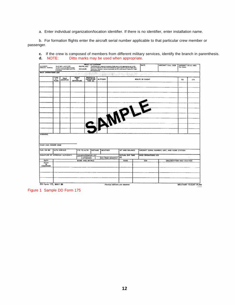
CHAPTER 1- FLIGHT PLANNING 1-1. Applicable Regulations. a. General: Army personnel engaged in the operation of Army aircraft shall comply with applicable: (1) Military regulations. (2) DOD flight information publications (FLIP). (3) Federal aviation regulations, laws, and rules. (4) Host country regulations, laws, and rules. (5) International Civil Aviation Organization (ICAO) regulations. (6) Aircraft operator's manuals and checklists. (7) Non aviation federal and state laws applicable to Army aviation operations. b. DOD FLIP does not provide procedure charts for all airfields that have instrument approach procedures. Required procedure charts may be added to the DOD FLIP by direct contact with the HQ U.S. Army Aeronautical Services Agency (USAASA), ATTN: ATAS-AI, 9325 Gunston Road, Suite N319, Fort Belvoir, VA 22060-5582, or the U.S. Army Aeronautical Services Detachment-Europe (USAASD-E). Use of commercial or host country products must be approved by either HQ USAASA or USAASD-E (ENAME region) as a supplement to DOD FLIP, per AR 95-2. c. Smoking is prohibited in, or within 50 feet of, Army aircraft. d. Procedures for packaging, handling, and air transportation of dangerous materials are described in AR 95-27, TM 38-250, and AR 55-203. Aircrews assigned to move dangerous materials in Army aircraft will comply with the requirements listed in these publications. e. Aircraft must be grounded during refueling, arming, oxygen servicing, and loading or unloading of flammable or explosive cargo. Aircraft will be grounded for maintenance per the appropriate maintenance publication. f. Army aviators will comply with the provisions of AR 95-1, and applicable portion of the Federal Aviation Regulations (FAR) Part 91 and Part 105, specifically addressed in AR 95-1. In the event of a conflict between the wording found in AR-95-1 and that found in the FARs, Army aviators are expected to comply with AR 95-1. The U.S. Army Aeronautical Services Agency (USAASA) has negotiated with the Federal Aviation Administration (FAA) and has obtained written authorization to deviate, in certain instances, from the requirements stipulated in the FARs. Lighting requirements for night vision training, and alternate airport weather requirements, are examples of the Army’s authorization to deviate from Federal Aviation Regulations. 1-2. DD FORM 175 MILITARY FLIGHT PLAN. The following are instructions for filling out the DD Form 175 (Figures 1 & 2) Military Flight Plan with notes provided for additional clarification. The sample flight plans are only examples of some of the ways to fill out a flight plan. There are many varied combinations that may serve the purpose for the flight. The use of checkmarks X's, specific verbiage, etc. is insignificant. Remember: It is important to convey the precise intent of the aviator through his flight plan to ATC. ITEM (1) DATE -- Enter date of flight in local time. ITEM (2) AIRCRAFT CALL SIGN -- This entry is limited to 7 charac ters. Enter the following:
6
a. Use the applicable code followed by the last five digits of the aircraft tail/bureau number. R - ARMY E - EVAC G - Army National Guard
NOTE: Formation flights will use only the radio call sign of the leader's aircraft.
b. Special US Army non-tactical call signs must be approved by the Director, USAASA, and will be entered as spoken with an assigned number to complete 5 or fewer alphanumeric charac ters (e.g. Pat 62, Saf 11, etc.). ITEM (3) AIRCRAFT DESIGNATION AND TD CODES
a. AIRCRAFT DESIGNATION - Enter the military designation of the aircraft. In formation flights of the same type aircraft, enter the number of aircraft in the flight and the designation (e.g., 6/H-1). For formation flights of mixed type aircraft, enter the lead aircraft and identify the other type aircraft in the REMARKS section (e.g., for an H-58 and a H-1 in formation, the DESIGNATION block entry is "2/B06/U" ("U" is the TD code) and the REMARKS would contain the entry #2 aircraft is a H-1/U.
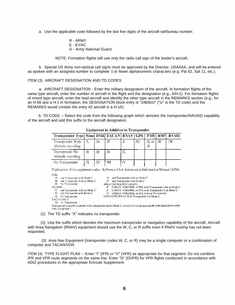
b. TD CODE -- Select the code from the following graph which denotes the transponder/NAVAID capability of the aircraft and add this suffix to the aircraft designation.
(1) The TD suffix "X" indicates no transponder. (2) Use the suffix which denotes the maximum transponder or navigation capability of the aircraft. Aircraft with Area Navigation (RNAV) equipment should use the W, C, or R suffix even if RNAV routing has not been requested. (3) Area Nav Equipment (transponder codes W, C, or R) may be a single computer or a combination of computer and TACAN/VOR. ITEM (4) TYPE FLIGHT PLAN -- Enter "I" (IFR) or "V" (VFR) as appropriate for that segment. Do not combine IFR and VFR route segments on the same line. Enter "D" (DVFR) for VFR flights conducted in accordance with ADIZ procedures in the appropriate Enroute Supplement.
7
ITEM (5) TRUE AIRSPEED -- Enter TAS to be maintained at initial cruising altitude/flight level. This entry is not required for VFR local flights. ITEM (6) POINT OF DEPARTURE -- Enter the location identifier of the departure aerodrome or the point (NAVAID or fix) where IFR will begin. If there is no location identifier, enter the installation name.
NOTE: Aerodrome location identifiers entered on the DD 175 shall consist of three or four alphanumeric characters. If the identifier in the US IFR Supplement has four letters, do not use the first letter, "K". If the identifier in the Alaska Enroute Supplement has four letters, do not use the first letter, "P." Four-letter identifiers are used on international flight plans. ITEM (7) PROPOSED DEPARTURE TIME (Z) -- Enter the proposed departure time in Coordinated Universal Time (UTC); allow sufficient time for Base Operations to process the flight plan. For activation of an airborne segment (e.g., after enroute delay), enter the proposed time for beginning that segment.
NOTE: Pilots must advise Base Operations or the tie-in FSS serving the departure, stopover, or enroute delay aerodrome when actual departure time will be delayed one hour or more beyond the filed proposed departure time, and provide an updated proposed departure time. When departing non-military fields, the pilot must ensure that the actual departure time is passed to the tie-in FSS servicing the departure field. This can be done by pilot request through the tower or by the pilot direct to the tie-in FSS. If the take-off time is not passed to the tie-in FSS, the aircraft will arrive unannounced at the next destination. ITEM (8) ALTITUDE
a. For IFR flights, enter the initial cruising altitude /flight level in hundreds of feet (e.g., enter 6000 feet as "60", 15,000 feet as "150", FL 240 as "240", etc.). For VFR flights, enter the initial cruising altitude in hundreds of feet (e.g., enter 4500 feet as "45"). For IFR/VFR-on-top, enter "OTP" and an altitude if so desired (e.g., "OTP" or "OTP 125").
b. If a subsequent enroute altitude change(s) is planned, enter the requested altitude/flight level and location of the change in the REMARKS section.
c. If an altitude block is desired, enter the lower altitude of the requested block, the letter "B", and the top of the block (e.g., 60B80). ITEM (9) ROUTE OF FLIGHT
a. For composite flight plans, do not combine IFR and VFR route segments on the same line.
b. If a radar departure or VFR climb is desired, enter this request in the REMARKS section. The first point in the route of flight should be the planned NAVAID or fix for entering enroute structure (i.e. VOR, TACAN, TACAN/DME fix, named intersection, etc.).
c. If a DP is used, enter the DP coded identifier (if none is available, enter the DP name and number), followed by either the DP termination point, or the transition fix (e.g., CLIOS 1 Departure, enter "CLIOS 1· CLIOS;" CLIOS 1 Departure with Banbi transition, enter "CLIOS 1. Banbi).
d. Clearly define the route of flight by using NAVAID identifiers, fix radial distance, airway/jet route designations, named intersections, or RNAV waypoints. The absence of airway identifiers between fixes/NAVAIDs indicates direct flight. To transition from one airway to another at an unnamed intersection, enter the designations of the two airways, separated by a space (e.g., YKM V4 V187 TCM).
e. Enter "Local" if the flight is to be conducted VFR within the designated local flying area and expected to terminate at the base of departure or an installation under the operational control of the base of departure.
8
f. For VFR flight plans, the last fix entered is the point from which the final leg is begun to the destination. g. For IFR flight plans, the last fix entered is: (1) The identifier of the nearest appropriate IAF, transition fix, or NAVAID which most clearly establishes the route of flight to the destination to include identifying the intended approach when possible. A single five-letter combination serves as the fix name, assigned identifier, and computer code and should be used when published. If a fix is co-located with a NAVAID, LOM, ILS marker, waypoint, or other type fix, the five-letter name/name-code applies to both. Fixes may also be filed using fix radial distance which consists of NAVAID identifier, three characters for azimuth, and three characters for distance in nautical miles (e.g., MCC 220017), or by listing the latitude and longitude. (2) If a Standard Terminal Arrival (STAR) is planned, enter the coded identifier of the STAR or the coded transition identifier if a transition is used (e.g., BOIDS EIGHT ARRIVAL enter as "BOIDS8", or with the Wichita Falls transition, enter "SPS.BOIDS8"). h. For a composite flight plan the last entry in the ROUTE OF FLIGHT is the fix/facility at which the
transition is made. Comply with paragraph f. above if the final leg to destination is VFR, and comply with paragraph g. above if the final leg to destination is IFR. i. STOPOVER FLIGHT PLANS (1) Each leg after the initial leg of a stopover flight plan is entered as described in ITEMS (4) through (11). (2) In parenthesis following the last entry of successive legs, enter the hours of fuel on board (e.g., (3+30)). (a) If in flight refueling is planned, enter an additional time group in brackets following the fuel on board to show the additional flight time attainable after the refueling (e.g. 3+30 [2+30]). (b) If an alternate is required, enter the airfield identifier and the ETE to the alternate in parenthesis with the fuel on board entry. (i.e., 3+30 SKF 0+30). (3) Enter VOID time in the REMARKS section as described in ITEM (12). j. ENROUTE DELAYS (1) HOLDING DELAY - Flight plans will normally be presented as one continuous flight. A holding delay will be shown immediately after the holding fix (e.g., BANBI/D 0+10 V7). No remarks are necessary. (2) TERMINAL AREA DELAY - Enter the delay location identifier as the last item in the route of flight. Do not make an entry in the TO block; enter the time required to fly the segment in the ETE block. Explain the delay as a remark on the next line in the ROUTE OF FLIGHT block; do not make entries in any other blocks on this line. Precede the delay remark with a circled "R" to indicate that the information to follow should be transmitted as a remark. Enter a "D" and the length of the delay, the delay location identifier, and the identifier of the final destination (e.g., R D 0+15 BSM RND). Complete ITEMS (4) through (11) for the subsequent leg of flight. Enter VOID time in the REMARKS as described in ITEM (12). NOTE: Use this delay for practice multiple approaches. k. AREA NAVIGATION (RNAV) PROCEDURES (1) Pilots filing flight plans which include random RNAV routes shall: (a) Indicate the appropriate RNAV capability suffix on the flight plan.
9
(b) Identify each waypoint defining the route of flight with a NAVAID identifier, fix name, fix radial distance, or airfield identifier. (c) When practical, use established departure/arrival routing to and from the random RNAV portion for the flight plan route (i.e., a DP, published instrument departure procedure, local area procedure, STAR, etc.). Begin and end the random route over published fixes. The last fix entered in the route of flight is according to ITEM (9)g above. (d) Avoid prohibited and restricted airspace by three (3) nautical miles unless permission has been obtained to operate in that airspace. Advise appropriate ATC facilities when permission has been obtained. (e) File a minimum of one waypoint in each ARTCC's area over which the random portion of flight will be conducted. Such waypoints must be located within 200 NM of the preceding ARTCC's boundary. (f) File an additional route description waypoint for each turnpoint in the route. (2) RNAV routes may be filed with latitude/longitude coordinate navigation capability, independent of VOR/TACAN references when at or above FL 390 using the following procedures: (a) Define the route of flight after the departure fix, including each intermediate fix (turnpoint) and the arrival fix for the destination airfield in terms of latitude/longitude coordinates plotted to the nearest minute. The arrival fix must be identified by both latitude/longitude coordinates and fix identifier (i.e., 2933/09839 SKF). (b) Comply with ITEM (9)(K)(1)(a), (c), and (d) above. (3) Limitations to the use of random RNAV routes: (a) Fly all routes/route segments in Great Circle tracks. (b) Contact Air Traffic Control for inflight requests for RNAV clearances or amendments. ITEM (10) TO -- Enter location identifier of full stop or final destination (as appropriate) opposite the last line entry in the ROUTE OF FLIGHT. If there is no location identifier, enter the aerodrome name. ITEM (11) ESTIMATED TIME ENROUTE
a. VFR Flight Plan - The time from takeoff to a position over the destination airfield, including known or preplanned enroute delays (practice airwork, approaches, landings, etc.)
b. IFR Flight Plan - The time planned to fly from the takeoff to the destination airfield, via flight plan route, to the last fix shown in the route of flight. See NOTES below.
NOTE 1: FAR 91.169(a) states ETE will be to a point over the destination airfield. This does not mean to the IAF serving the airfield. NOTE 2: Include the procedure turn (PT) time only when planning to execute an approach that requires a PT. NOTE 3: Remember, ETE is only an estimate. NOTE 4: Time for enroute delays should be figured in fuel management procedures.
10
c. Composite Flight Plan - For each IFR segment, use time planned to fly the segment exclusive of enroute delays; for each VFR segment, use time planned to fly the segment including known delays (practice airwork, landings, etc.) ITEM (12) REMARKS -- Enter information essential to safe and efficient control of air traffic. Service codes and other pertinent information should also be included in this section.
a. Aircraft on an IFR flight plan equipped with ADF as the only enroute NAVAID will be identified as 'ADF only".
b. Enter "Hazardous cargo", "Inert devices", or both (as appropriate).
c. SERVICE CODES PPR (number) - PPR number, if applicable. (e.g. PPR 0723) S - Service required (e.g., FSI-5) R - Aircraft will remain over night (e.g., DAA-R) d. Enter in plain English any other pertinent information deemed necessary to be transmitted to the destination.
NOTE: For stopover flight plans, identify the destination to which the information applies (e.g., MGM-S LSF-PPR 0723 S R Mission Code 6R44).
e. VOID Time - Required for all stopover and/or terminal area delay flight plans. Calculate VOID time by taking the total time from takeoff to final destination, rounded to the next whole hour. (e.g., for total time 4+20, enter "VOID 5+00"). NOTE: This entry is required by the FAA. ITEM (13) RANK/HONOR CODE -- See the FLIP GP for FLIGHT PLAN VIP CODES. For stopover flight plans, enter pick-up and drop-off points of VIP (e.g., R50 OZR to MGM). ITEM (14) FUEL ON BOARD -- Enter total time that an aircraft can stay aloft while flying the planned profile with the fuel available at initial takeoff using procedures recommended in the appropriate flight manual. NOTE: Do not include fuel required for run-up and taxi. ITEM (15) ALTERNATE AIRFIELD -- Alternate airfields will be selected on the basis of criteria contained in AR 95-1. If IFR on a stopover flight plan, the alternate listed is for the first point of intended landing. Alternates required for subsequent stops will be included in the ROUTE OF FLIGHT section of the flight plan. Use the location identifier to identify alternate airports. If there is no location identifier, enter the installation name. ITEM (16) ETE TO ALTERNATE -- Enter the time required to fly from original destination to the alternate aerodrome, based on flight at the last cruising altitude.
NOTE: The time figured is to a point over the alternate airfield. ITEMS (17) and (18) NOTAMS/WEATHER -- Included as a pre-flight reminder and may be used as directed locally. ITEM (19) WEIGHT AND BALANCE -- File a DD Form 365-4 with the flight plan or certify on the flight plan that the loading for the proposed flight does not exceed the loading limits. When making this certification cite a previously filed DD Form 365-4 for the particular aircraft and enter one of the following:
11
a. N/A - When the aircraft flight manual does not require completion of DD Form 365-4 for each mission. b. ATTACHED - If the DD Form 365-4 is attached.
c. (Filed at) _ /(date) , when citing a previously filed Form for a normal loading (e.g., OZR/l Feb 92)
d. When required, a new DD Form 365-4 (Weight & Balance) shall be filed with the military base operations office when flights originate from bases having such offices; or with the Airport Manager or other suitable person when flights originate from established flying areas without a military base operations office. NOTE: Refer to AR 95-1. ITEM (20) AIRCRAFT SERIAL NUMBER/UNIT/HOME STATION
a. Enter aircraft serial number. For formation flights enter only the lead aircraft's number. b. Enter the aircraft unit of assignment.
c. Enter the location identifier of home station (e.g., 69-50151/214th AVN Co/PDT). ITEM (21) SIGNATURE OF APPROVAL AUTHORITY -- Signed by the appropriate approval authority. ITEM (22) CREW, PASSENGER LIST
a. If the list of crew members will not fit in the given blocks, the crew list may be continued on the back of the DD Form 175 original copy, or attached on a separate piece of paper. The attachment may be a copy of crew orders, or any piece of paper with the appropriate information on it. When a crew list is attached, check the appropriate box.
b. If a passenger manifest is used, check the appropriate box. A single manifest for stopover flight may be filed at the departure point, provided it clearly shows crew/passenger changes for subsequent stops. ITEM (23) ACTUAL DEPARTURE TIME (Z) -- For base operations use. ITEM (24) DUTY -- Enter the symbol for the duty to be performed by each crew member listed, as prescribed by AR 95-1. For formation flights, identify the crew duty symbol and position of the aircraft in formation (e.g., IP/l, P/2, etc.). ITEM (25) NAME AND INITIALS
a. The name of the pilot in command must appear in the first block of the crew list on the DD form 175. b. Names of all crew members except the pilot in command may be listed separately and attached to the
flight Plan (i.e., a copy of crew orders or other crew list).
c. If there are more crew members than blocks, the list may be continued on the back of the original copy of the DD Form 175. ITEM (26) RANK -- Enter the appropriate military rank or suitable civilian classification (e.g., CDR, 2LT, CW3, SGT, DAC, etc.). ITEM (27) SSN -- Optional. (Army pilots use ‘On File” or leave it blank.) ITEM (28) ORGANIZATION AND LOCATION
12
a. Enter individual organization/location identifier. If there is no identifier, enter installation name.
b. For formation flights enter the aircraft serial number applicable to that particular crew member or passenger.
c. If the crew is composed of members from different military services, identify the branch in parenthesis. d. NOTE: Ditto marks may be used when appropriate.
Figure 1 Sample DD Form 175

13
Figure 2. Sample DD Form 175, cont'd.
14
1-3. Weather/Weather Briefings.
a. Weather. All pilots are responsible and accountable for the procurement and analysis of aeronautical weather reports and forecasts, including recognition of critical weather situations and estimating visibility while in flight. b. Weather briefing. Local commanders will establish policies specifying when DD Form 175-1 is required to be filed with the DD 175 flight plan (AR 95-1). Weather information for the DD 175-1 will be obtained from a military weather facility. If a military forecaster is not available, pilots are expected to obtain the best weather briefing available for the specific mission to be flown. Army priority for obtaining a formal DD 175-1 weather briefing is: (1) US military weather forecaster. (2) Combat Weather Team or supporting Operational Weather Squadron (OWS). (3) Military Aircrew Information Service (MAIS). (4) Other military or government weather service. 1-4. Maps And Charts. Specific aeronautical charts, maps and geospatial information are available in hardcopy (print), graphic, or digital formats. AR 95-2 establishes the authorization and allowances of aeronautical products. The USAASA/USAASD-E is the mandatory point of contact for obtaining aeronautical products or generating/changing to aeronautical product(s) requirements. Direct contact with NIMA and DLA is not authorized. 1-5. Notice To Airmen (Notam) System. a. Time-critical aeronautical information, which is either temporary in nature or not sufficiently known in advance to permit publication on aeronautical charts or in other operational publications, receives immediate dissemination via the Military NOTAM System.
NOTE: NOTAM information is that aeronautical information that could affect a pilot’s decision to make a flight. It includes such information as airport or primary runway closures, changes in the status of navigational aids, ILS’s, radar service availability, and other information essential to plan en route, terminal, or landing operations.
b. The DOD Internet NOTAM Service (DINS) is the current method for aircrews to obtain safe, reliable and up to date aeronautical information for flight planning. The web-based service provides NOTAM data and access at locations not serviced by current weather distribution systems (AWDS). Aircrews will consider DINS as the preferred means of obtaining NOTAMs. The operational web address is http://www.notams.jcs.mil. c. Minimum system requirements are a 486 IBM compatible PC with connectivity to the NIPRNET (LAN or dial up modem), and an internet browser (Netscape or Internet Explorer versions 3.0 or higher). Airfield Managers must ensure that the installation local area network managers configure their internet servers to optimize aircrew access to DINS. Army Airfields that are required to input NOTAMs must meet the system requirements listed on the web address http://baseops.notams.jcs.mil. d. For assistance contact the POC listed on the webpage or Voice Mail: DSN 994-4205/6/7 and request to speak to a military coordinator Commercial: (703) 904-4484 Government Fax: DSN 851-3440
15
1-6. Alternate Airport Requirements. When use of an alternate airport is required in filing an IFR flight plan (AR 95-1) reference should be made to the instrument approach procedure to be used for the alternate selected to determine alternate airport minimums. If the airport is not authorized for use as an alternate, the let ters "NA" will follow the symbol under the minimum box for military procedures.
NOTE: If the pilot must proceed to the selected alternate airport, the alternate ceiling and visibility minimums are disregarded and the published landing minimum is applicable for the new destination using facilities as appropriate to the procedure. In other words, the alternate airport becomes the new destination, and the pilot uses the landing minimum appropriate to the type of procedure selected. 1-7. Landing Fees. During preflight, check the FLIP for any airfield of intended use to determine if a landing fee is charged. If you think they charge a landing fee, have sufficient funds with you, but consider the following:
CFR Title 14, Part 152, Appendix D, Para. 26 states, in part, “All facilities of the Airport developed with Federal aid and all those usable for the landing and taking off of aircraft, will be available to the United States at all times, without charge, for use by government aircraft in common with other aircraft, except that if use by government aircraft is substantial, a reasonable share, proportional to such use, of the cost of operating and maintaining facilities so used, may be charged.” If you do have to pay a landing fee, obtain a receipt. If possible relay the name of the person, the organization, airport name, and their telephone numbers to the United States Army Aeronautical Services Agency, Airspace Support Division. (Note: If you use an FBO’s services or facilities you may have to pay. Example: Marshaling, use of rest rooms and lounge, etc.; these are not landing fees.)
CHAPTER 2 - DEPARTURE PROCEDURES 2-1. IFR Takeoff Minimums. During preflight planning prior to departure on an IFR flight plan, reference should be made to FLIP Terminal publications to determine whether a Departure Procedure (DP) has been established and whether or not alternate take-off minimums should be applied. Takeoff minimums or departure procedures apply if the symbol is shown in the minimums box. 2-2. Departure Procedures. Published DPs assist pilots conducting IFR flight in avoiding obstacles during climbout to minimum enroute altitude (MEA). a. Obstacle clearance is based on the aircraft climbing at 200ft per nautical mile, and climbing to 400ft AGL above airport elevation before turning, unless otherwise specified in the procedure. A slope of 152 feet per mile, starting no higher than 35 feet above the departure end of the runway, is assessed for obstacles. A minimum of 48 feet of obstacle clearance is provided for each mile of flight. (1) For heliports and helipads, instrument departure obstacle clearance is based on helicopters climbing 352’ per nautical mile and climbing to 400, above takeoff area elevation before turning. A slope of 304’ per mile starting at the end of the departure area is assessed for obstacles. (2) If obstacles penetrate the slope, obstacles avoidance procedures are specified. These procedures may be: a ceiling and visibility to allow the obstacles to be seen and avoided; a climb gradient greater than 200 feet per mile (352’ for heliports); detailed flight maneuvers; or, a combination of the above. In extreme cases, IFR takeoff may not be authorized. EXAMPLE: Rwy 17, 300-1 or standard with minimum climb of 220'/NM to 1100.
16
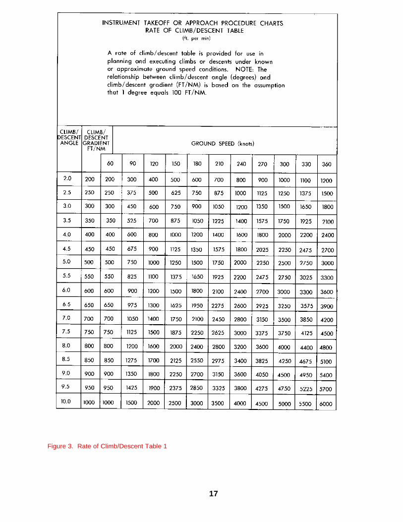
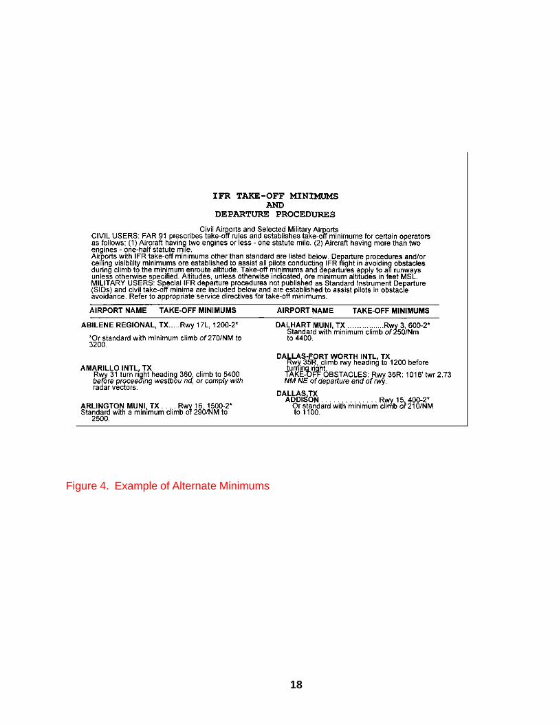
b. Climb gradients are specified when required for obstacle clearance. Crossing restrictions in DPs may be established for traffic separation or obstacle clearance. When no gradient is specified, the pilot is expected to climb at least 200 feet per mile to MEA unless required to level off by a crossing restriction. EXAMPLE: "CROSS ALPHA INTERSECTION AT OR ABOVE 4000; MAINTAIN 6000." The pilot climbs at least 200 feet per mile to 6000. c. Climb gradients may be specified to an altitude, above which the normal gradient applies. EXAMPLE: "MININUM CLIMB 340'/NM TO 2700'. " The pilot climbs at least 340 feet per mile to 2700', then at least 200 feet per mile to MEA. d. Some procedures require a climb in visual conditions to cross the airport (or an airport NAVAID) at or above an altitude. EXAMPLE: "Climb visually to cross the airport at or above 8800', then climb via R-293 to ABC VOR.” (1) The specified ceiling and visibility minimums will be enough to allow the pilot to see and avoid obstacles near the airport. Obstacle avoidance is not guaranteed if the pilot maneuvers farther from the airport than the visibility minimum. (2) That segment of the procedure which requires the pilot to see and avoid obstacles ends when the aircraft crosses the specified point at the required altitude. Thereafter, standard obstacle protection is provided. e. Each pilot, prior to departing an airport on an IFR flight, should consider the type of terrain and other obstacles on or in the vicinity of the departure airport and: (1) Determine if a departure procedure is available for obstacle avoidance. (2) Determine if obstacle avoidance can be maintained visually or that the departure should be followed. (3) Determine what action will be necessary and take such action that will assure a safe departure. 2-3. Obstacle Clearance - Departure Rate of Climb/Descent Table. The minimum rate-of-climb quoted in the IFR take-off minimums and departure procedures section quotes figures in feet per nautical mile. The rate-of-climb indicators in aircraft are measured in feet per minute. Rate of descent for a descent for a precision approach is based on the angle of the glide path/slope. Therefore, a rate-of-climb/descent table has been developed (Figure 3) and appears on the inside of the back cover of the IAP volumes. 2-4. Departure Procedures. Airports with takeoff minimums other than standard are described in airport listings on separate pages, titled IFR TAKE-OFF MINIMUMS AND DEPARTURE PROCEDURES at the front of each IAP book. The approach chart and DP chart for each airport with non-standard take-off minimums is annotated with a
special symbol . The use of this symbol indicates that the separate listing should be consulted. These minimums also apply to Graphic DPs unless the Graphic DPs specify different minimums.
17
Figure 3. Rate of Climb/Descent Table 1
18
Figure 4. Example of Alternate Minimums
19
CHAPTER 3 - ENROUTE
3-1 Instrument Flight Rules (IFR). General:
a. Prior to departure from within controlled airspace or prior to entering controlled airspace, a pilot must submit a complete flight plan and receive an air traffic clearance, if weather conditions are below VFR minimums. Instrument flight plans may be submitted to either the nearest military base operations, nearest FSS, or ATCT. Deliver either in person or by telephone (or by radio if no other means is available). Pilots should file IFR flight plans at least 30 minutes prior to estimated time of departure to preclude possible delay in receiving a departure clearance from ATC. To minimize your delay in entering Class B, Class C, Class D and Class E surface areas at destination when IFR weather conditions exist or are forecast at that airport, an IFR flight plan should be filed before departure. Otherwise, a 30 minute delay is not unusual in receiving an ATC clearance because of time spent in processing flight plan data. Traffic saturation frequently prevents control personnel from accepting flight plans by radio. In such cases, the pilot is advised to contact the nearest FSS to file a flight plan.
NOTE - There are several methods of obtaining IFR clearances at nontower, non-FSS, and outlying airports. The procedure may vary due to geographical features, weather conditions, and the complexity of the ATC system. To determine the most effective means of receiving an IFR clearance, pilots should ask the nearest FSS the most appropriate means of obtaining the IFR clearance.
b. Instrument flight rules (IFR) flight. Destination weather must be forecast to be equal to or greater than the published weather planning minimum for the approach procedure to be flown at ETA through 1 hour after ETA. When there are intermittent weather conditions, predominant weather will apply. Aviators flying helicopters may reduce destination and alternate Category A visibility minimums by 50 percent, but not less than 1/4 mile or metric equivalent. Reduction of visibility for approaches labeled"copter only" is not authorized. Category II approach procedures may not be used in destination or alternate weather planning. 3-2 Lost Communications. a. Whether two-way communications failure constitutes an emergency depends on the circumstances, and in any event, it is a determination made by the pilot. FAR Part 91.3(b) authorizes a pilot to deviate from any rule in Subparts A and B to the extent required to meet an emergency. b. In the event of two-way radio communications failure, ATC service will be provided on the basis that the pilot is operating in accordance with FAR Part 91.185. 3-3 Terrain Clearance. a. OFF ROUTE OBSTRUCTION CLEARANCE ALTITUDE (OROCA) - CONUS OROCA is an off-route altitude which provides obstruction clearance with a 1,000 foot buffer in nonmountainous terrain areas and a 2,000 foot buffer in designated mountainous areas within the U.S. This altitude may not provide signal coverage from ground-based navigational aids, air traffic control radar, or communications coverage. b. OFF ROUTE TERRAIN CLEARANCE ALTITUDE (ORTCA) - OCONUS WHAT'S AN ORTCA?- An Off Route Terrain Clearance Altitude is published by the Defense Mapping Agency on Enroute Low Altitude Charts. Introduced on CONUS charts, in 1995, as Off Route Obstruction Clearance Altitudes (OROCA's), ORTCA's are designed to provide 3000' AGL terrain clearance and assist aircrews utilizing random navigation route structures in those areas where off route navigation is permitted.
20
CHAPTER 4 - APPROACH 4-1. Instrument Approach Procedures. Instrument Approach Procedures Charts (IAPs) provide pilots with essential information landing at destination airports having instrument approaches or for the execution of a missed approach if the instrument approach is not capable of being completed. IAPs provide safe flight headings/turns/altitudes for orderly transitions from enroute flight to an approach for landing--OR to safe missed approach procedures when airports are experiencing Instrument Meterological Conditions (IMC) Also, within the IAPs are associated airport diagrams. Airport diagrams are specifically designed to assist movement of ground traffic at airports with complex runway/taxiway configurations. Airport diagrams are not intended to be used for approach, landing or departure operations. 4-2 Types Of Published Instrument Approach Procedures. Instrument Approach Procedures are designed to provide the pilot with all electronic aid information, together with procedural and other pertinent data required to execute the procedure.
a. Department Of Defense (DoD) Procedures. The Department of Defense (DOD) Instrument Approach Procedures are printed in two variations in CONUS; Terminal Low Altitude United States (VOL 1 through 15), and Terminal High Altitude United States (NE, NW, SE, SW). Overseas HI/LOW IAP’s are combined. DOD FLIP is the official publication medium for terminal information for use by the U.S. Army, U.S. Navy and U.S. Air Force.
(1) The Terminal HI/LOW procedures are issued as indicated on the appropriate volumes. A
Scheduled Terminal Change Notice for the Low’s will be published at the four/eight week mid-point and will contain revisions, additions and deletions to the last issue of the basic volume. Revisions, additions and deletions to the HI’s will be published by unscheduled Urgent Change Notices (UCNs) and issued as necessary. Changes to both the High and Low procedures will be issued by Notice to Airman (NOTAM) until the applicable changes are published.
(2) Terminal procedures publications must be used in conjunction with NOTAMs, TCNs, UCNs, and
other related publications during mission planning or for in-flight reference. It is imperative that aircrew members first consult the TCN and/or UCN before making any decision regarding which Terminal Procedures are current at the airport of intended landing or departure. If the airport of intended landing/departure is not listed in the Table of Contents of the TCN, UCN, or is not listed in NOTAMs, the information in the basic volume has not changed.
b. Civil Procedures. DOD FLIP does not contain approach procedures for all airfields or all available instrument procedures for a specific airfield. Civil and military users of civilian procedures must refer to the Government Instrument Approach Procedures publications published by the NOS for non-standard or restrictions to IFR Alternate Minimums. DOD policy for inclusion of civil instrument procedures in DOD FLIP products is to provide only those procedures to meet mission requirements. Procedures required for training can be obtained from the NOS procedures books. It is permissible to reproduce these NOS procedures and issue them to aviators for their missions. Civil procedures supporting U.S. Army requirements may be added to DOD FLIP with justification by direct contact with Director USAASA. c. Host Nation Procedures. Director USAASA and the U.S. Army Aeronautical Services Detachment - Europe (USAASD-E) are approving authorities for inclusion of Host Nation approach procedures in DOD FLIP. When it is not practical to have procedures published or issued, the approving office , after review, may authorize small, isolated, or special mission units to use Host Nation AIPs for flight operations. USAASA or USAASD-E, when approving the use of Host Nation AIPs will establish operating minimums and airport restrictions, if needed, that do not conflict with host nation rules. An automatic cancellation date will be set for all procedures approved for use under special conditions and not published in FLIP, this approval will not exceed 56 days. Any extension to use procedures beyond this date must be re-processed and-approved. d. Jeppesen Procedures. Jeppesen Sanderson, Inc. of Englewood, Colorado; a privately owned and operated company, publishes instrument approach procedures and other related flight information publications on
21
a worldwide basis. The use of Jeppesen Approach Procedures are only approved for specific overseas AIRPORTS after a review of the procedure by Director USAASA or commander USAASD-E. 4-3. Procedural Identification (Ref: Chapter 1, Section 6, TERPS). Terminal instrument procedures are identified to be meaningful to the pilot and to permit ready identification of air traffic control phraseology. a. Straight-in Approach. Procedures which meet criteria for authorization of straight-in landing minima shall be identified by the type of navigational aid(s) which provide final approach guidance and the runway to which the final approach course(s) are aligned; e.g., ILS Rwy 18R, LOC BC Rwy 7, TACAN Rwy 4, NDB Rwy 21, VOR Rwy 15, VOR/DME Rwy 6, ILS or TACAN Rwy 9, etc. A slash (/) shall indicate that more than one type of equipment must be used to execute the final approach; e.g., VOR/ DME, etc. When procedures are combined the word "or" shall indicate either type of equipment may be used to execute the final approach; e.g., ILS or TACAN, ILS or NDB, VOR/DME or TACAN etc. When the same final approach guidance is used to the same runway, the procedures shall be identified as follows: TACAN 1 Rwy 36, TACAN 2 Rwy 36, VOR 1 Rwy 18, VOR 2 RWY 18, etc. All procedures should be carefully examined to determine if you are capable of flying the entire procedure. In some instances, the missed approach segments are designated to/from a NAVAID with which Army aircraft are not equipped, i.e., TACAN.
b. Circling Approach. When a procedure does not meet criteria for straight-in landing minimums authorization, it shall be identified by the type of navigational aid which provides final approach guidance, and an alphabetical suffix. The first procedure formulated shall bear the suffix "A" even though there may be no intention to formulate additional procedures. If additional procedures are formulated, they shall be identified alphabetically in sequence, e.g., VOR-A, VOR/DME-B, NDB-C, LDA-D, etc. A revised procedure shall bear its original identification. c. Copter Procedures. Helicopter only procedures shall bear an identification which includes the term "COPTER," the type of facility providing final approach course guidance, and a numerical identification of the final approach course, e.g.,'COPTER VOR 090, COPTER NDB 270, COPTER PAR 327, COPTER ASR 327, etc. If the procedure includes an arc final approach, the word "ARC" shall be used, and shall be followed by a sequential number, e.g., COPTER VORTAC ARC 1, COPTER VOR/DME ARC 2, COPTER TACAN ARC 3, etc. d. Host Nation Approach. Host nation procedures may be identified differently than stated above. Without the host nation's approval, we cannot legally change the procedure title. All approach procedures should be thoroughly studied to determine if they can be flown. Examples of these can be found in the ENAME Low Altitude IAP Books, e.g., NDB/DME ILS RWY 26 at Kinloss, 2 NDB RWY 29 Deurne Antwerp, TACAN to PAR RWY 08 at Kinloss. 4-4. Units of Measurement. Units of measurement shall be expressed as set forth below: a. Bearings, Courses, and Radials. Bearings and courses shall be expressed in degrees magnetic. Radials shall also be expressed in degrees magnetic, and shall further be identified as radials by prefixing the letter "R" to the magnetic bearing FROM the facility (e.g., R-027 or R-010). b. Altitudes. The unit of measurement for altitude in this publication is feet. Published heights below the transition level (18,000 feet in the CONUS, and as designated by the host nation) shall be expressed in feet above MSL; e.g. 17,900 feet. Published heights at and above the transition level (18,000 feet) shall be expressed as Flight Levels; e.g., FL180, FL190, etc. c. Distances. All distances shall be expressed in nautical miles (6076.1 feet per NM) and tenths thereof, except when applied to visibility, which shall be expressed in statute miles and the appropriate fractions thereof. Expression of visibility values in nautical miles or metric equivalent is permitted in overseas areas where it coincides with the host nation practice. Runway visual range (RVR) shall be expressed in feet; except in host nation procedures, the metric equivalent may be used. d. Speeds. Aircraft speed shall be expressed in knots.
22
4-5. Aircraft Categories. (Ref. Ch 2, Sec 1, TERPS; FAR Part 97; FLIP GP Ch 2). a. The United States Standard for Terminal Instrument Procedures (TERPs) provides for the differences in performance by placing aircraft in one of five categories and establishing approach minimums for each category.
b. The five approach categories (A thru E) are based on 1.3 times the stall speed in the landing configuration. If it is necessary to maneuver at speeds in excess of the upper limit of the speed range for the aircraft's category, the minima for the next higher approach category will be used. For example, an aircraft which falls into Category C but is maneuvering to land to a speed in excess of 140 knots, but less than 166 knots, will use approach Category D minima.
APPROACH SPEED CATEGORY
A Speed less than 91 knots.
B Speed 91 knots or more but less than 121 knots.
C Speed 121 knots or more but less than 141 knots.
D Speed 141 knots or more but less than 166 knots.
E Speed 166 knots or more.
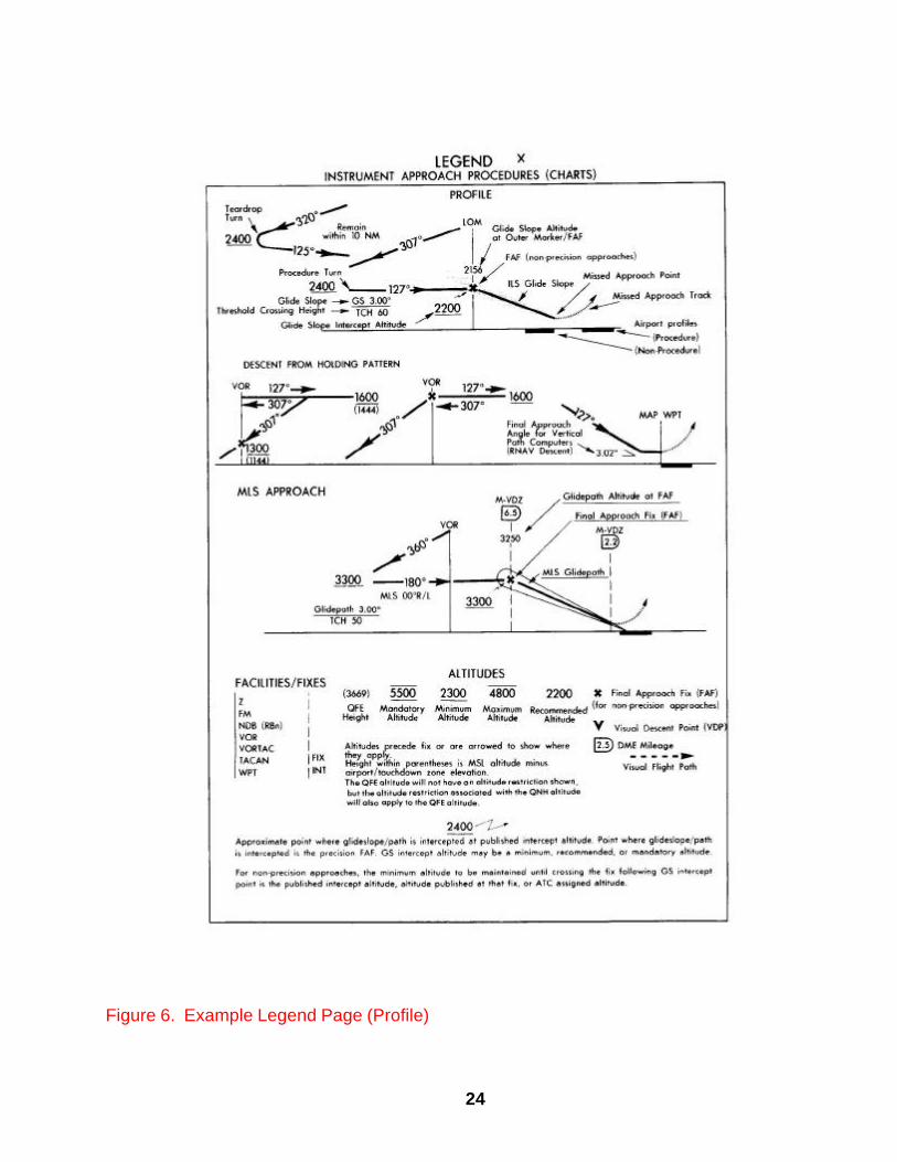
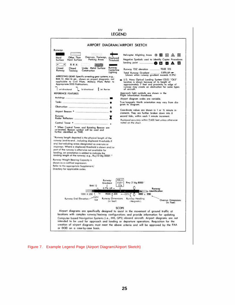
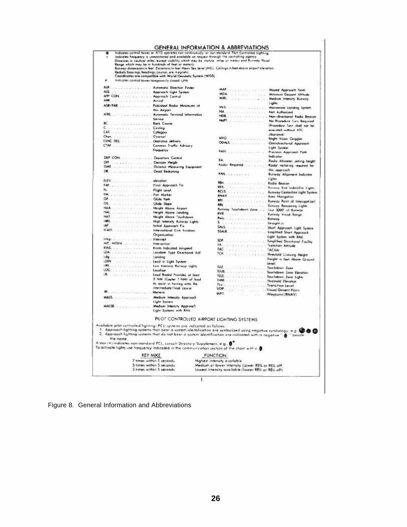
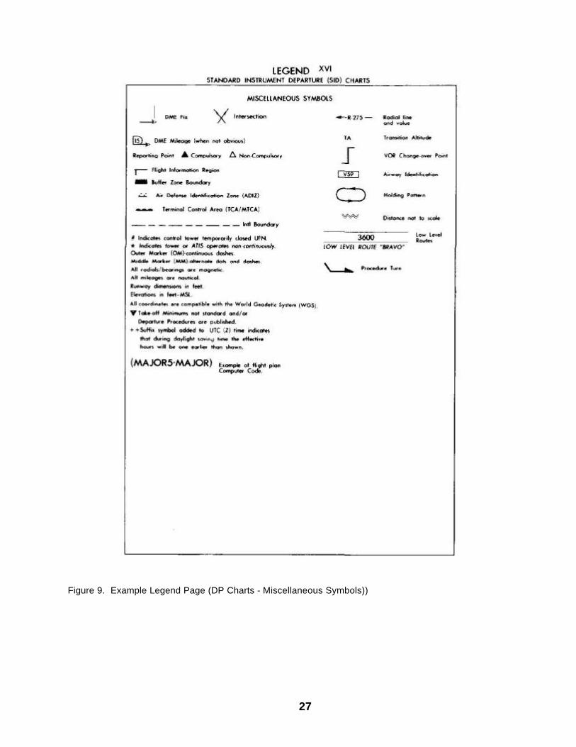
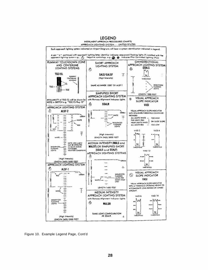
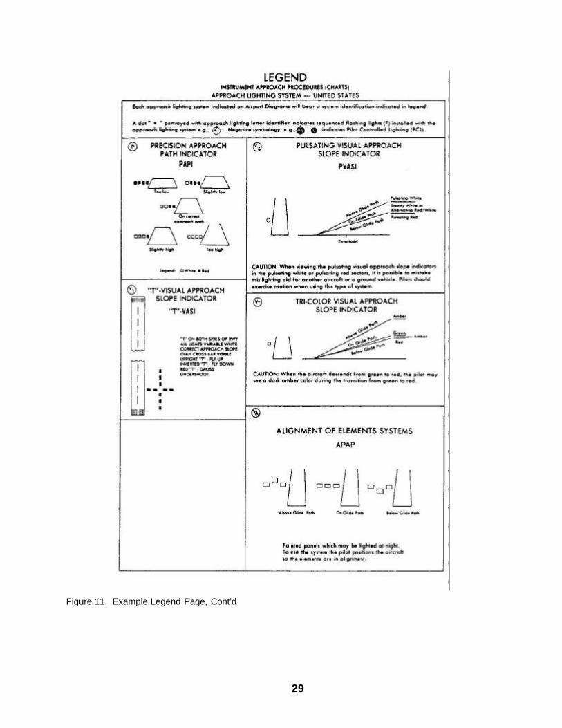
NOTE: All US Military Helicopters may utilize the aircraft approach Category A minima published in authorized FLIP publications. Since aircraft speeds are used in determining turning radii and obstacle clearance areas for circling and turning missed approaches, helicopters operating at speeds greater than CAT A will use the higher category minima. Procedures containing the word "COPTER" in the procedure title, i.e, COPTER VOR 190, are approved under TERPs Helicopter Criteria for helicopter use only and are restricted to 90 knots indicated airspeed unless a lesser speed is annotated on the approach plate.. 4-6. IAP Legend Pages. The legends shall define and depict all symbols used in the presentation of IAP's and Airport Diagrams, and provide information pertaining to general items of interest and a listing of all abbreviations. Figures 5 - 11 are examples of legend pages taken from instrument approach procedures charts.

23
Figure 5. Example Legend Page (Plainview Symbols)
24
Figure 6. Example Legend Page (Profile)
25
Figure 7. Example Legend Page (Airport Diagram/Airport Sketch)
26
Figure 8. General Information and Abbreviations
27
Figure 9. Example Legend Page (DP Charts - Miscellaneous Symbols))
28
Figure 10. Example Legend Page, Cont’d
29
Figure 11. Example Legend Page, Cont’d
30
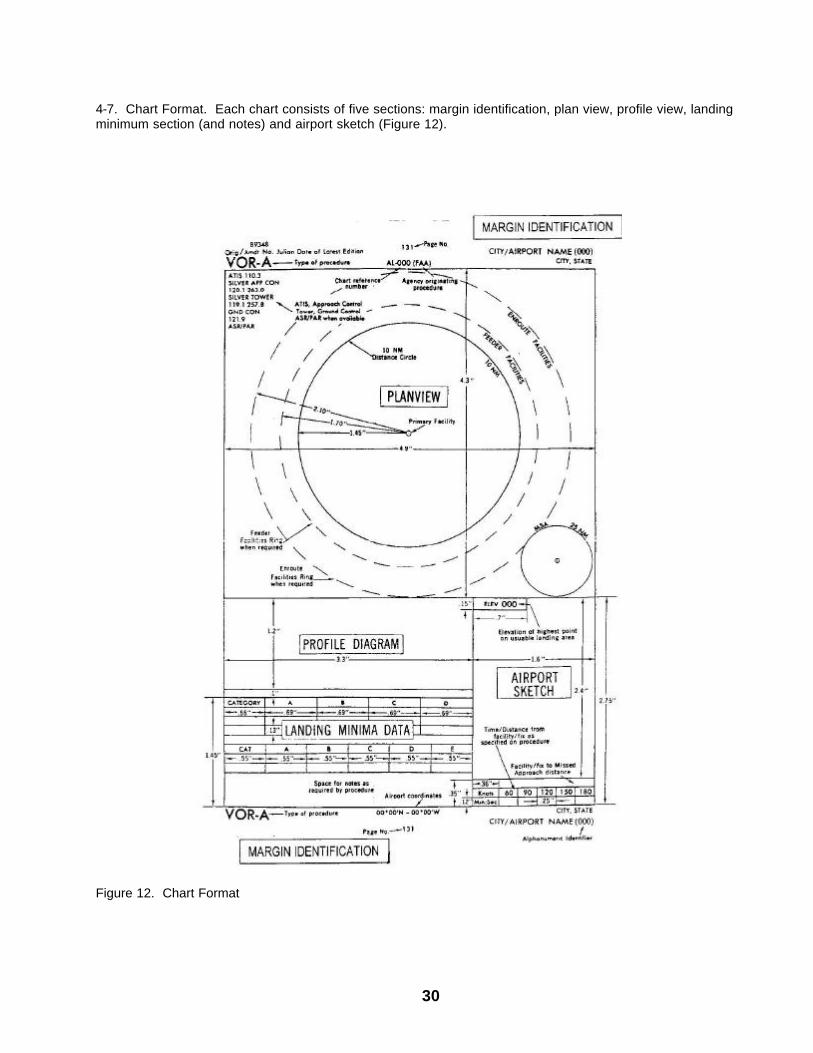
4-7. Chart Format. Each chart consists of five sections: margin identification, plan view, profile view, landing minimum section (and notes) and airport sketch (Figure 12).
Figure 12. Chart Format
31
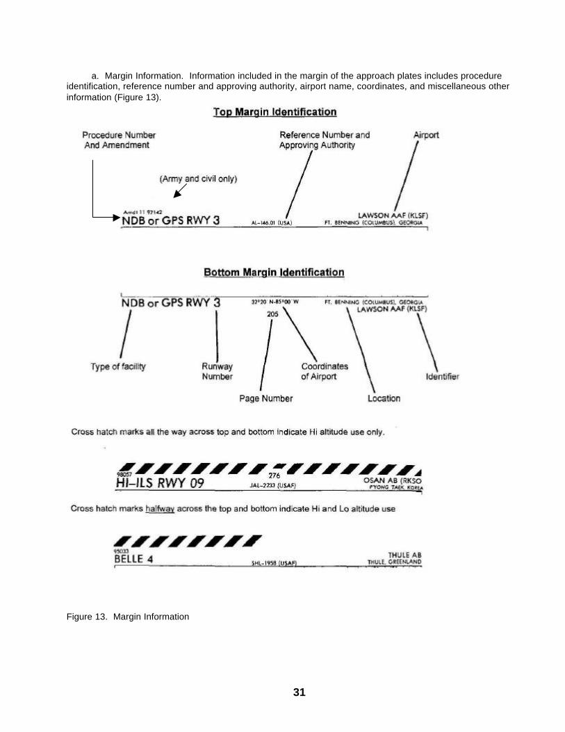
a. Margin Information. Information included in the margin of the approach plates includes procedure identification, reference number and approving authority, airport name, coordinates, and miscellaneous other information (Figure 13).
Figure 13. Margin Information
32
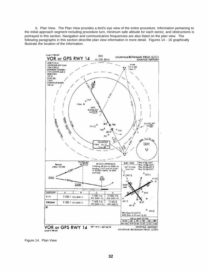
b. Plan View. The Plan View provides a bird's eye view of the entire procedure. Information pertaining to the initial approach segment including procedure turn, minimum safe altitude for each sector, and obstructions is portrayed in this section. Navigation and communication frequencies are also listed on the plan view. The following paragraphs in this section describe plan view information in more detail. Figures 14 - 16 graphically illustrate the location of the information.
Figure 14. Plan View
33
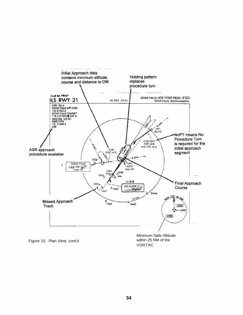
(1) Format. Normally, all information within the plan view is shown to scale. Data shown within the 10 NM distance circle (inner ring) is always shown to scale (Figure 14). The dashed circles, called concentric rings, are used when all information necessary to the procedure can not fit to scale within the limits of the plan view area. These circles then serve as a means to systematically arrange this information in their relative position outside and beyond the 10 NM distance circle. These concentric rings are labeled Enroute Facilities and Feeder Facilities and are normally centered on the approach facility. (2) Enroute Facilities Ring. (Figure 14.) Radio aids to navigation, fixes and intersections that are part of the Enroute Low Altitude Airway structure and used in the approach procedure are shown in their relative position on this Enroute Facilities Ring. (3) Feeder Facilities Rings. (Figure 14.) Radio aids to navigation, fixes and intersections used by the air traffic controller to direct aircraft to intervening facilities/fixes between the enroute structure and the initial approach fix are shown in their relative position on this Feeder Facilities Ring. When the initial approach fix is part of the enroute structure, there may be no need to designate additional routes for aircraft to proceed to the initial approach fix (IAF). However, in some cases it is necessary to designate feeder routes from the enroute structure to the initial approach fix. Only those feeder routes which provide an operational advantage shall be established and published. These should coincide with the local air traffic flow. The length of the feeder route shall not exceed the operational service volume of the facilities which provide navigational guidance unless additional frequency protection is provided. Enroute airway obstacle clearance criteria shall apply to feeder routes. The minimum altitude established on feeder routes shall not be less than the altitude established at the IAF. (4) The availability of RADAR (Figure 15) is indicated below the communications information by the appropriate and applicable letters "ASR," "PAR," "ASR/PAR.:" These terms are applied as follows: (a) ASR - Airport Surveillance Radar instrument approach procedure is available at the airport. (b) PAR - Precision Approach Radar instrument approach procedure is available. (5) The term "initial approach" encompasses the following: (a) In the initial approach, the aircraft has departed the enroute phase of flight, and is maneuvering to ent er an intermediate or final segment of the instrument approach.
(b) An initial approach may be made along prescribed routes within the terminal area which may be along an arc, radial, course, heading, radar vector, or a combination thereof. Procedure turns, holding pattern descents, and high altitude teardrop penetrations are initial approach segments.
(c) Initial approach information is portrayed in the plan view of instrument approach charts by
course lines with an arrow indicating the direction. Minimum altitude and distance between fixes are also shown with the magnetic course.
(6) When an approach course is published on an ILS procedure that does not require a procedure turn (NoPT, Figure 15), the following applies:
34
Figure 15. Plan View, cont’d Minimum Safe Altitude within 25 NM of the VORTAC
35
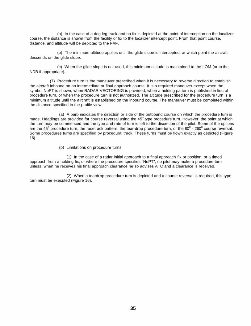
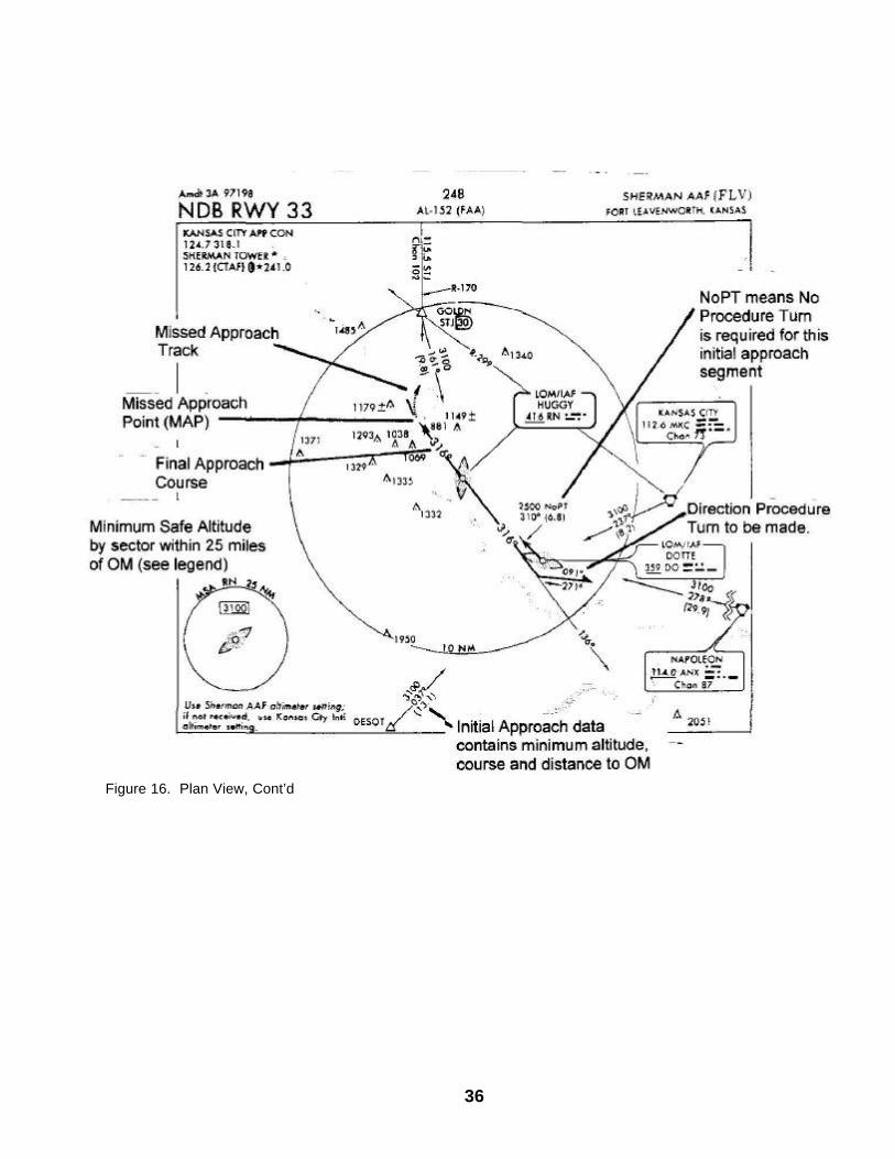
(a) In the case of a dog leg track and no fix is depicted at the point of interception on the localizer course, the distance is shown from the facility or fix to the localizer intercept point. From that point course, distance, and altitude will be depicted to the FAF. (b) The minimum altitude applies until the glide slope is intercepted, at which point the aircraft descends on the glide slope. (c) When the glide slope is not used, this minimum altitude is maintained to the LOM (or to the NDB if appropriate). (7) Procedure turn is the maneuver prescribed when it is necessary to reverse direction to establish the aircraft inbound on an intermediate or final approach course. It is a required maneuver except when the symbol NoPT is shown, when RADAR VECTORING is provided, when a holding pattern is published in lieu of procedure turn, or when the procedure turn is not authorized. The altitude prescribed for the procedure turn is a minimum altitude until the aircraft is established on the inbound course. The maneuver must be completed within the distance specified in the profile view. (a) A barb indicates the direction or side of the outbound course on which the procedure turn is made. Headings are provided for course reversal using the 45o type procedure turn. However, the point at which the turn may be commenced and the type and rate of turn is left to the discretion of the pilot. Some of the options are the 45o procedure turn, the racetrack pattern, the tear-drop procedure turn, or the 80o - 260o course reversal. Some procedures turns are specified by procedural track. These turns must be flown exactly as depicted (Figure 16). (b) Limitations on procedure turns. (1) In the case of a radar initial approach to a final approach fix or position, or a timed approach from a holding fix, or where the procedure specifies "NoPT", no pilot may make a procedure turn unless, when he receives his final approach clearance he so advises ATC and a clearance is received. (2) When a teardrop procedure turn is depicted and a course reversal is required, this type turn must be executed (Figure 16).
36
Figure 16. Plan View, Cont’d
37
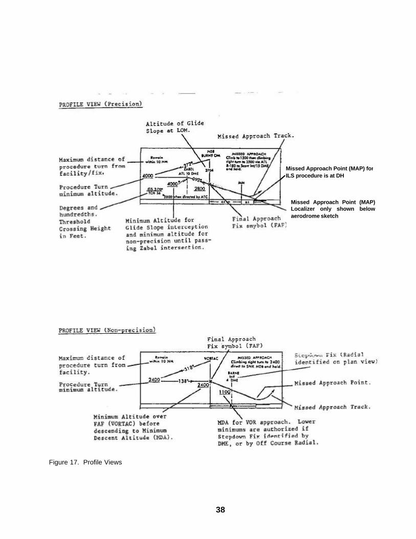
(3) When a holding pattern replaces the procedure turn, the standard entry and the holding pattern must be followed except when RADAR VECTORING is provided or when NoPT is shown on the approach course. As in the procedure turn, the descent from the minimum holding pattern altitude to the final approach fix altitude (when lower) may not commence until the aircraft is established on the inbound course. (4) The absence of the procedure turn barb in the Plan View indicates that a procedure turn is not authorized for that procedure. (c) A procedure turn is not required when the symbol NoPT appears on an approac h course is shown on the Plan View. If a procedure turn is desired, ATC approval must be obtained and the procedure turn altitude must be maintained until established on the inbound course. c. Profile Views. Profile views (Figure 17) show a side view of the procedures. These views include the minimum altitude and maximum distance for the procedure turn, altitudes over prescribed fixes, distances between fixes and the missed approach procedure. (1) Precision approach glide slope intercept altitude. This is a minimum altitude for glide slope interception after completion of procedure turn. It applies to precision approaches and, except where otherwise prescribed, it also applies as a minimum altitude for crossing the final approach fix in case the glide slope is inoperative or not used. (2) Stepdown fixes in non-precision procedures. A stepdown fix may be provided on the final, i.e., between the final approach fix and the airport, for the purpose of authorizing a lower MDA after passing an obstruction. This stepdown fix may be made by an NDB bearing, fan marker, radar fix, radial from another VOR, TACAN, or by DME when provided for as shown in Figure 17
38
Figure 17. Profile Views
Missed Approach Point (MAP) for ILS procedure is at DH
Missed Approach Point (MAP) Localizer only shown below aerodrome sketch
39
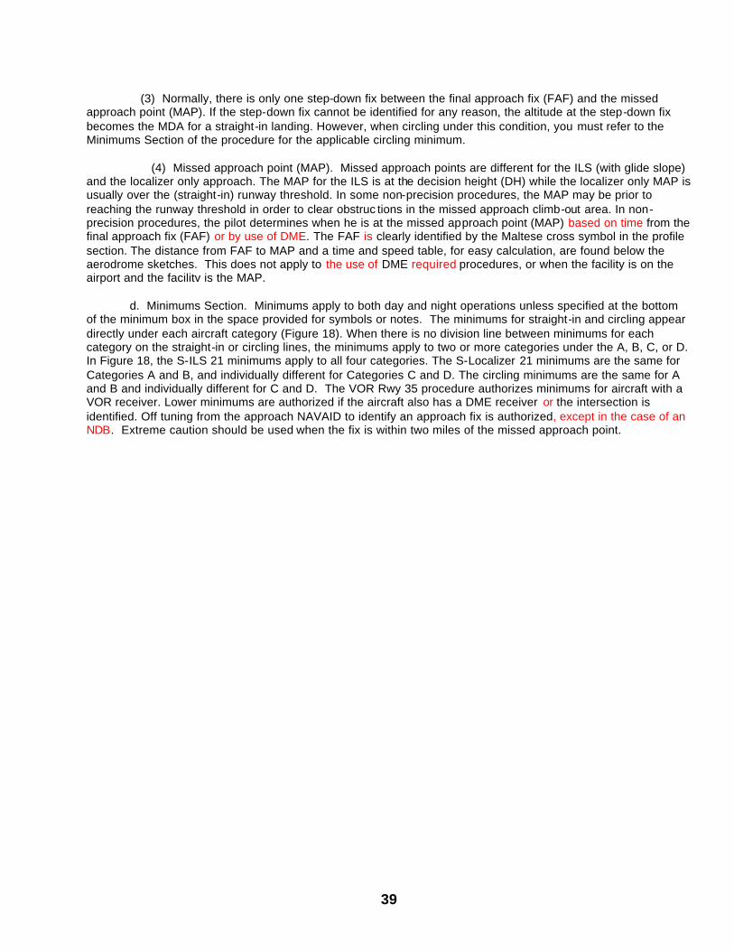
(3) Normally, there is only one step-down fix between the final approach fix (FAF) and the missed approach point (MAP). If the step-down fix cannot be identified for any reason, the altitude at the step-down fix becomes the MDA for a straight-in landing. However, when circling under this condition, you must refer to the Minimums Section of the procedure for the applicable circling minimum. (4) Missed approach point (MAP). Missed approach points are different for the ILS (with glide slope) and the localizer only approach. The MAP for the ILS is at the decision height (DH) while the localizer only MAP is usually over the (straight-in) runway threshold. In some non-precision procedures, the MAP may be prior to reaching the runway threshold in order to clear obstruc tions in the missed approach climb-out area. In non-precision procedures, the pilot determines when he is at the missed approach point (MAP) based on time from the final approach fix (FAF) or by use of DME. The FAF is clearly identified by the Maltese cross symbol in the profile section. The distance from FAF to MAP and a time and speed table, for easy calculation, are found below the aerodrome sketches. This does not apply to the use of DME required procedures, or when the facility is on the airport and the facilitv is the MAP. d. Minimums Section. Minimums apply to both day and night operations unless specified at the bottom of the minimum box in the space provided for symbols or notes. The minimums for straight-in and circling appear directly under each aircraft category (Figure 18). When there is no division line between minimums for each category on the straight-in or circling lines, the minimums apply to two or more categories under the A, B, C, or D. In Figure 18, the S-ILS 21 minimums apply to all four categories. The S-Localizer 21 minimums are the same for Categories A and B, and individually different for Categories C and D. The circling minimums are the same for A and B and individually different for C and D. The VOR Rwy 35 procedure authorizes minimums for aircraft with a VOR receiver. Lower minimums are authorized if the aircraft also has a DME receiver or the intersection is identified. Off tuning from the approach NAVAID to identify an approach fix is authorized, except in the case of an NDB. Extreme caution should be used when the fix is within two miles of the missed approach point.
40
Figure 18.**Examples of Minimums Section
Alternate Minimums not standard.**Army refer to AR 95-1
41
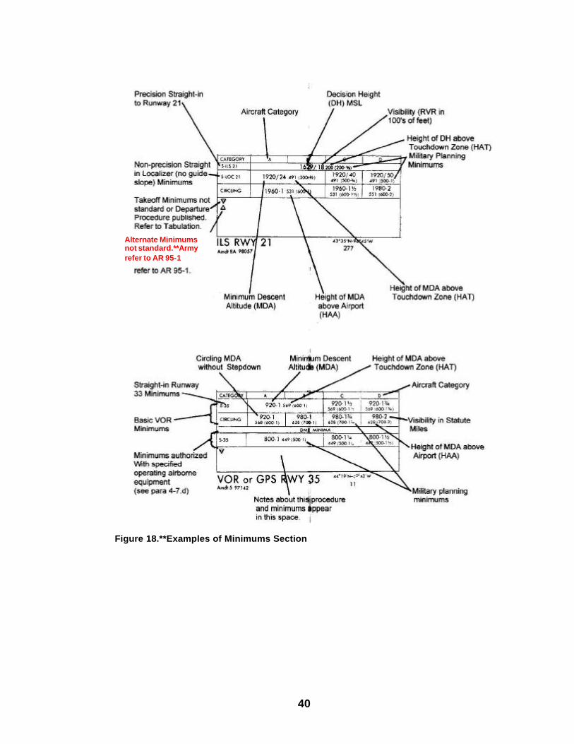
(1) Straight-In Minimums. Straight-in minimums are shown on instrument approach procedure charts when the final approach course of the instrument approach procedure is within 30º of runway alignment and a normal descent can be made from the IFR altitude shown on the instrument approach procedures to the runway surface. When either the normal rate of descent or the runway alignment factor of 30º is exceeded a straight-in minimum is not published, and a circling minimum applies. The pilot must be cleared to land straight when conducting a circling approach. The fact that a straight-in minimum is not published does not preclude the pilot from landing straight-in if he has the active runway in sight in sufficient time to make a normal landing. Under such conditions and when Air Traffic Control has cleared him for landing on that runway, he is not expected to circle even though only circling minimums are published. If he desires to circle at a controlled airport, he should advise ATC.
(2) Circling Minimums. The circling minimums published on the instrument approach chart provide
adequate obstruction clearance and the pilot should not descend below the circling altitude until the aircraft is in a position to make final descent for landing. Sound judgment and knowledge of his and the aircraft capabilities are the criteria for a pilot to determine the exact maneuver in each instance since the airport design, the aircraft design, position, altitude and airspeed must all be considered. The following basic rules apply:
(a) Maneuver the shortest path to the base or downwind leg as appropriate under minimum
weather conditions. There is no restriction from passing over the airport or other runways. (b) It should be recognized that many circling maneuvers may be made while VFR flying is in
progress at the airport. Standard left turns or specific instruction from the controller for maneuvering must be considered to land when circling to land.
(c) At airports without a control tower, it may be desirable to fly over the airport to determine wind
and turn indicators, and to observe other traffic which may be on the runway or flying in the vicinity of the airport. (3) Remote Altimeter Settings. The weather planning minimums must be computed when the pilot knows that a MDA or DH has been raised due to having to use a remote altimeter setting . In some cases, the new minimums will be shown in the minimum box (Figure 19 below). When not shown, the method illustrated in Figure 19 will be used to compute the new weather planning minimums.

42
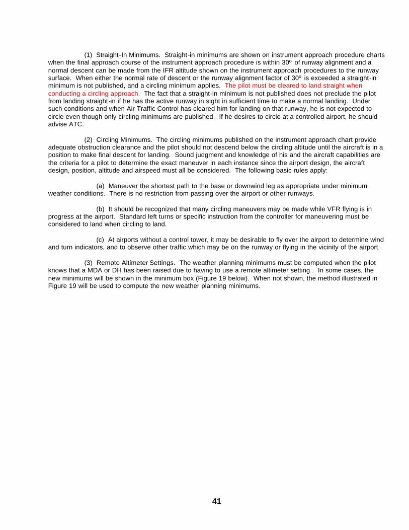
Figure 19: Recomputing MDA and DH e. Airport Sketch. The airport sketch (Figure 20) contains specific data about runways, elevations, etc, It also provides information on approach times from the FAF to the MAP.
960 feet - MDA with local altimeter 120 feet - increase when using remote altimeter 1080 feet - New MDA 466 feet - Less airport elevation 614 feet - Rounded UP - (700 - 1) *Figure above shows the computation for circling weather planning minima
43
Figure 20: Airport Sketch
4-8. Procedural Component Operation. a. Operative runway lights are required for night operation. b. When the facility providing course guidance is inoperative, the procedure is not authorized. VOR/DME procedures are not authorized if either VOR or DME is inoperative. c. When the ILS glide slope is inoperative or not used, the published straight -in localizer minimum applies. d. Compass locator, precision radar, or DME may be substituted for the ILS outer marker. e. Surveillance radar may be a substitute for the ILS outer marker. DME, at the glide slope site, may be substituted for the outer marker when published on the ILS procedure to identify the localizer FAF. f. Facilities that establish a stepdown fix, i.e., 75 MHz FM, off course VOR radial, etc. are not components of the basic approach procedure, and applicable minimums for use, both with or without identifying the stepdown fix, are published in the minimums section (Fig. 19 above). g. Runway Visual Range (RVR) Minimums. To authorize RVR minimums, the following components and visual aids must be available in addition to basic components of the approach procedure: (1) Precision approach procedures. (a) RVR reported for the runway. (b) HIRL. (c) All weather runway markings
44
(2) Non-precision approach procedures. (a) RVR reported for the runway. (b) HIRL. (c) Instrument runway markings.
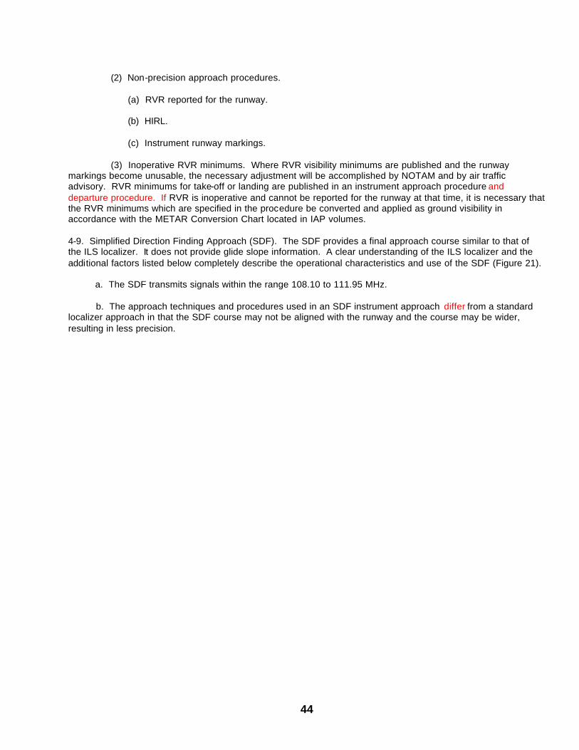
(3) Inoperative RVR minimums. Where RVR visibility minimums are published and the runway markings become unusable, the necessary adjustment will be accomplished by NOTAM and by air traffic advisory. RVR minimums for take-off or landing are published in an instrument approach procedure and departure procedure. If RVR is inoperative and cannot be reported for the runway at that time, it is necessary that the RVR minimums which are specified in the procedure be converted and applied as ground visibility in accordance with the METAR Conversion Chart located in IAP volumes. 4-9. Simplified Direction Finding Approach (SDF). The SDF provides a final approach course similar to that of the ILS localizer. It does not provide glide slope information. A clear understanding of the ILS localizer and the additional factors listed below completely describe the operational characteristics and use of the SDF (Figure 21).
a. The SDF transmits signals within the range 108.10 to 111.95 MHz.
b. The approach techniques and procedures used in an SDF instrument approach differ from a standard
localizer approach in that the SDF course may not be aligned with the runway and the course may be wider, resulting in less precision.
45
Figure 21: Example SDF Approach
46
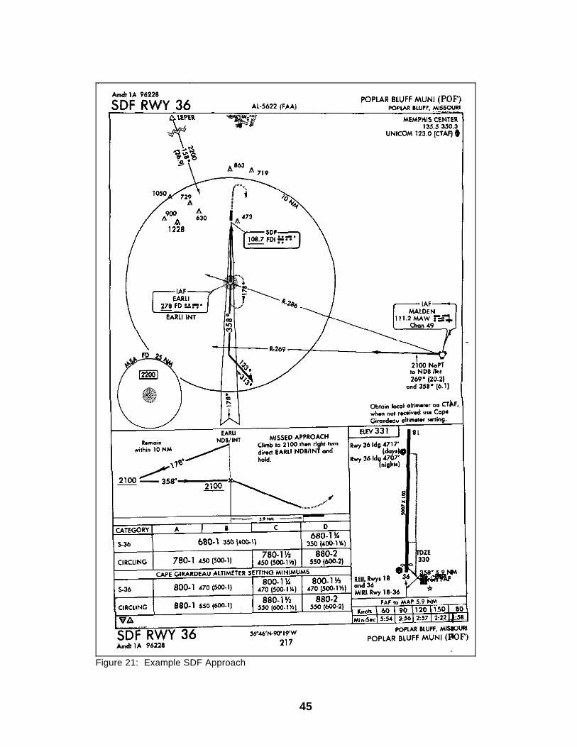
c. Identification consists of a three letter identifier transmitted in Morse Code on the SDF frequency. The appropriate instrument approach chart will indicate the identifier used at a particular airport. 10. Global Positioning System (GPS). The (GPS) consists of a worldwide signal and monitoring network and a broad array of military and civilian equipment. GPS includes a constellation of 24 satellites, in six orbit planes (four satellites per plane) in 10,898 NM orbits. This equates to an orbit period of 12 hours, or two orbits per day. This satellite constellation guarantees that at least five satellites are in view from any point on the earth 24 hours a day, providing three-dimensional (latitude, longitude and altitude) position and time reference information. GPS receivers validate signal information through what is called receiver autonomous integrity monitoring (RAIM). Isolation of a corrupt signal requires signal augmentation with local area barometric pressure or six satellites to be in view of the receiver and Fault Detection Error (FDE). In order for the aviation community to take advantage of the benefits provided by GPS, aircraft operators must have the necessary certified airborne equipment (TSO C-129 or military equivalent, i.e. AMCOM certification) approved and installed in their aircraft and published instrument approach procedures available to the user. Non-U.S. Government instrument approach procedures have to be reviewed and validated for compliance with TERPS criteria or equivalent level of safety before use by military aviators. a. GPS Nonprecision Approach Procedure Development. GPS instrument approach procedures are based on GPS airborne equipment meeting the enroute, terminal and non-precision requirements. (1) Procedure Identification. Instrument Approach Procedures based on GPS are identified by the prefix RNAV followed by the runway number or letter, as appropriate; such as RNAV RWY 12 for a straight-in, or RNAV-A which signifies a circling approach (Figure 22). See also Appendices 1 & 2.
47
Figure 22. GPS Approach
48
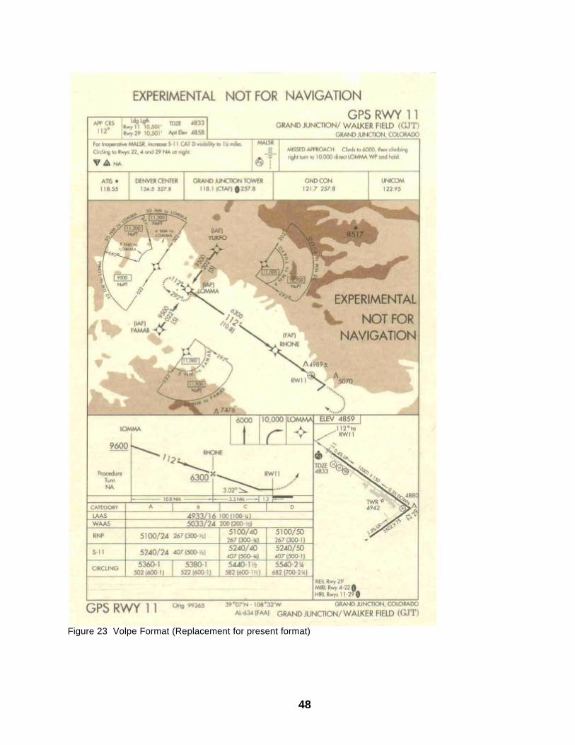
Figure 23 Volpe Format (Replacement for present format)
49
(2) Segments. GPS RNAV segments begin and end at a WP. WPs are used to identify the point at which GPS navigation begins and the point at which the procedure ends. WPs are also used to identify where routes change course; holding fixes; the final approach fix (FAF); and the missed approach point (MAP). Step-down fixes are defined as Along Track Distance (ATD) fixes, and there is no maximum number in any segment . Each WP is defined by latitude and longitude to nearest hundredth of a second, and identified with a five letter name. (3) Enroute. Standard enroute criteria applies to GPS enroute segments. (4) Feeder Routes. When the initial approach WP (IAWP) is not part of the enroute structure, feeder routes will be designated from the enroute structure to another feeder WP or to the IAWP. Enroute obstacle clearance applies in the feeder.
(5) Initial Approach Segment. The initial approach segment begins at the IAWP and ends at the intermediate WP (IWP) or the intermediate ATD fix. Normally, the IAWP will overlie an enroute fix or NAVAID. The length should not exceed 50 NM. When the IAWP is more than 30 NM from the airport reference point (ARP), the procedure is annotated with a note to advise the pilot to ensure the approach mode has been activated, i.e. Arm Approach Mode Prior to IAF. The angle of intercept between the initial and intermediate segments should be the minimum required for the procedure, and will not exceed 120°. A minimum of 1,000 feet of obstacle clearance, or 1,500 feet above terrain for airspace is provided in the initial segment. The optimum descent gradient is 250 feet/NM, and the maximum is 500 feet/NM in the initial segment.
(6) Course Reversal. When a course reversal is required, a holding pattern is provided in lieu of a PT. A minimum obstacle clearance of 1,000 feet is provided within the holding pattern area when the altitude permits a departure from holding at a normal descent to the Final Approach Waypoint (FAWP) altitude at a descent rate not to exceed 300 feet/NM. Course change at the FAWP or IWP will not exceed 15°. (Holding in lieu of a PT is at the IF/IAF (7) Intermediate Segment. The IWP may be shown as an ATD fix if no turn is required at the IWP. The intermediate should be aligned with the final. Course change at the FAWP will not exceed 15°. The minimum length is 5 NM, and the optimum is 10 NM. A minimum of 500 feet of obstacle clearance is provided in the intermediate segment. The optimum descent gradient is 150 feet/NM, and the maximum is 300 feet/NM in the intermediate segment. (8) Final Approach Segment. The final segment begins at the FAWP and ends at the MAWP. Any step-down fixes are defined as ATD fixes with reference to the next WP or runway. Straight-in approaches will not exceed 15° from the runway centerline extended (RCL), and the optimum alignment is to the threshold (THR). When the alignment exceeds 3° from the RCL, the optimum alignment is to a point 3,000 feet from the THR on the RCL. The optimum length is 5 NM, and the maximum is 10 NM. The minimum obstacle clearance provided in the final is 250 feet. The optimum descent gradient is 300 feet/NM, and the maximum is 400 feet/NM.The final descent gradient is computed by dividing the difference between the FAF (or Step-down) altitude and the touchdown zone elevation (TDZE) by the length of the final approach segment. (9) Circling Approach. The optimum alignment is to the center of the landing area, but may be to any portion of the useable landing surface. The location of the Missed Approach Waypoint (MAWP) can be anywhere along the final course between the FAWP and a point abeam the nearest useable landing surface. A minimum of 300 feet of obstacle clearance is provided in the circling area. The optimum descent gradient is 300 feet/NM, and the maximum is 400 feet/NM. The descent gradient is computed by dividing the difference between the FAF (or Step-down) altitude and the MDA by the length of the final approach segment. (10) Approach Minimums. The standard criteria spelled out in the Terminal Instrument Procedures Manual (TERPS) apply to computing GPS instrument landing minimums. (11) Missed Approach. The missed approach segment begins at the MAWP and ends at a point designated as the clearance limit. A straight, turning, or combination straight and turning missed approach may

50
be developed. A 40:1 or 152 feet/NM obstacle clearance surface is provided in the missed approach segment. The missed approach surface begins at the MDA minus the obstacle clearance and any other adjustments in the final. A IWP is designated at the MAP and at the end of the missed approach procedure. The missed approach will specify a clearance limit and an altitude suitable for holding or continued enroute navigation. (12) Minimum Safe Altitude. A common safe altitude is established for a 25 NM radius around the MAWP or Runway Threshold. The minimum safe altitude area provides 1,000 feet of clearance over the highest obstacle in the MSA.
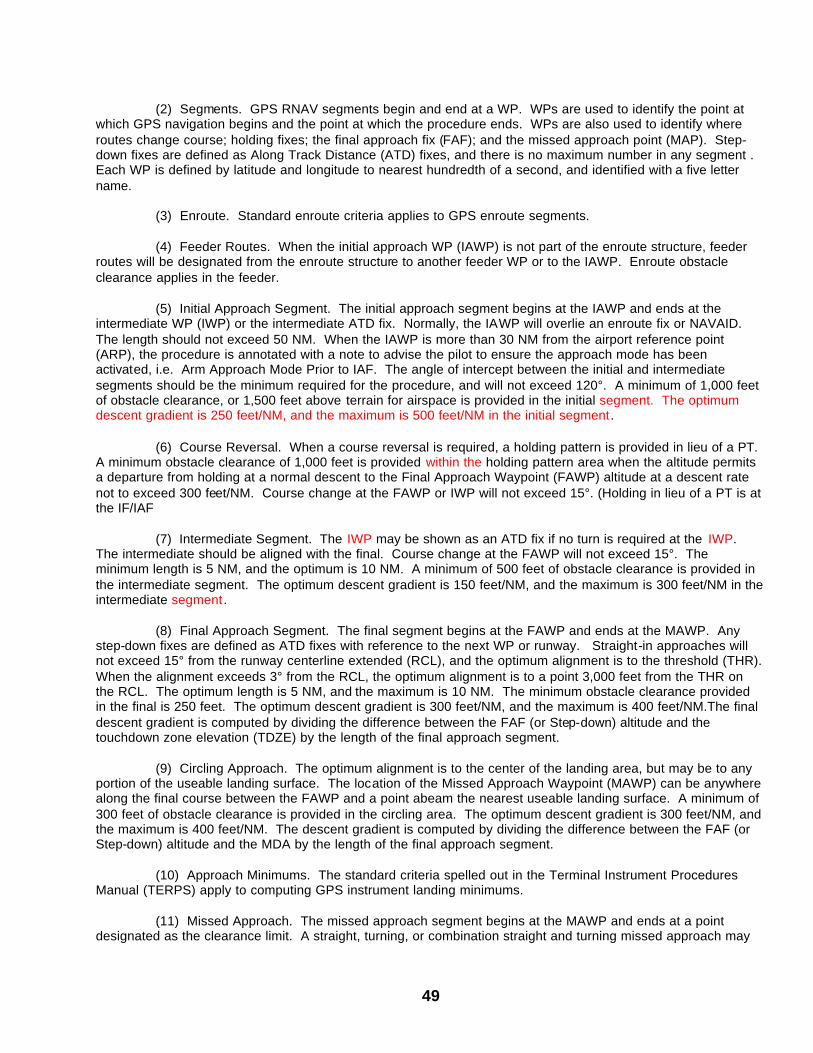
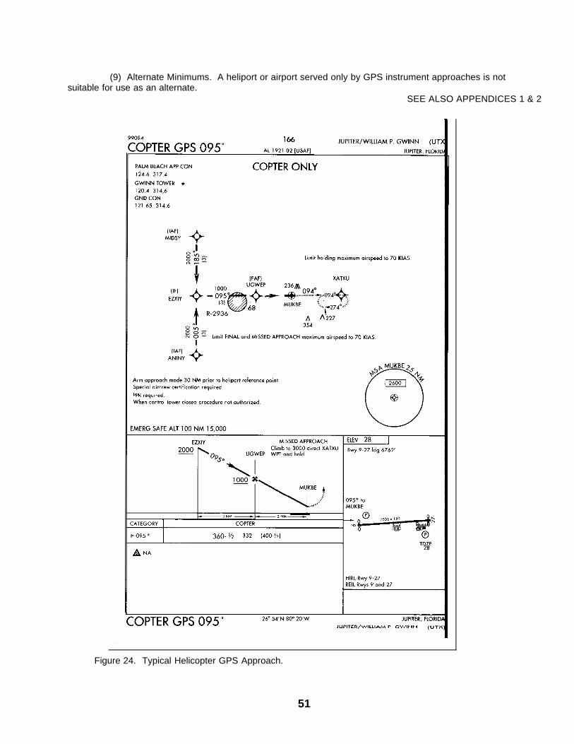
NOTE - With Terminal Arrival Area (TAA) MSA’s will not be provided. b. Helicopter RNAV Approaches. Helicopter instrument approach procedures are based on the premise that helicopters are approach category A aircraft with special maneuvering characteristics. Speed limitations incorporated in these procedures take advantage of the unique, slow speed capability of helicopters and allow the lowest possible landing minimums. Military (“Not for civil use”) approach procedures are designed for an airspeed not to exceed 90 KIAS in the final and missed approach segments. (1) Procedure Identification. Helicopter GPS instrument approaches to runways are identified by COPTER RNAV followed by the runway number or final bearing as appropriate; i.e. COPTER RNAV RWY 30, COPTER RNAV 160. A typical approach is shown at Figure 24. (2) Approach Design. The basic “T” configuration is considered the optimum. It affords flexibility and standardization of procedure design. (3) Initial Approach Segment. The initial begins at the IA F and ends at the IF or ATD fix form the FAF. Course change at the IF will not exceed 120°. IAF’s originate within 25 NM of the airport (ARP) or heliport (HRP). The length should not exceed 10 NM. A minimum of 1,000 feet of obstacle clearance is provided in the initial, with an optimum descend gradient of 400 feet/NM. (4) Course Reversal. A holding pattern will be provided at the IF or FAF when a course reversal is required to execute the approach. The holding pattern will be aligned within 30° of the intermediate or final course as appropriate. (5) Intermediate Segment. The intermediate begins at the IWP or ATD fix and ends at the FAF. The maximum length is 5 NM, and the recommended is 3 NM. The maximum course change at the FAF is 60°. A minimum of 500 feet of obstacle clearance is provided in the intermediate, with an optimum descent gradient of 400 feet/NM. (6) Final Approach Segment. The final approach begins at the FAF and ends at the MAWP. Helicopters are considered to be in a visual mode from the MAWP to the landing area. The final approach can be to a runway, to a heliport or to a point-in-space. For approaches to a runway the alignment will not exceed 30° from the RCL. The optimum length of the final is 3 NM. A minimum of 250 of obstacle clearance is provided in the final with an optimum descent gradient of 400 feet/NM, and a maximum of 600 feet/NM. Final segment descent gradient is computed from the FAF altitude to MDA.
(7) Missed Approach. The missed approach segment begins at the MAWP and ends at a clearance limit designated by a missed approach holding waypoint (MAHWP). Optimum routing is straight ahead to a direct entry into holding. The MAHWP will be located within 25 NM of the ARP/HRP. A 20:1 or 304 feet/NM obstacle clearance surface is provided in the missed approach segment. (8) Landing Minimums. Heliport Instrument Lighting System (HILS) or approved runway lighting is recommended for all helicopter GPS approach operations in order to receive the lowest possible landing minimums.
51
(9) Alternate Minimums. A heliport or airport served only by GPS instrument approaches is not suitable for use as an alternate.
SEE ALSO APPENDICES 1 & 2 Figure 24. Typical Helicopter GPS Approach.
52
c. Terminal Arrival Area (TAA) and Basic “T” Design. Transition from the enroute structure to the terminal environment requires specific ground tracks defined by ground based navigational facilities. These transitions can be difficult to develop in areas where terrain features interfere with signal radiation and reception. With the development of navigation systems that are independent of conventional navigational aids the possibility of creating a new transition system has emerged. Efforts to develop an efficient and standard instrument approach configuration has led to the development of the Terminal Arrival Area (TAA) concept. The TAA utilizes a Basic T segment configuration as a standard for area navigation (RNAV) approach procedures. The TAA combined with the Basic T is viewed as the optimum design for GPS procedures. The TAA approach consists of an Initial, Intermediate, Final and Missed Approach segments. In the Basic T approach configuration the alignment of the initial segment to the intermediate segment is 90° (See figure 25). The initial segment length may vary to meet descent gradients. The maximum length is 10 NM. The intermediate segment is aligned with the final segment, and turns over the fi nal approach fix (FAF) are not allowed. If a course reversal is required holding will be established in lieu of a procedure turn (PT) at the IF (IAF). The inbound holding course will be aligned with the inbound intermediate course. The optimum missed approach is a straight ahead climb with a direct entry into a missed approach holding pattern. If the missed approach routing is back to a T IAF, the missed approach holding pattern will be aligned with the initial inbound course, with a direct entry into holding. The standard TAA contains three areas; a straight -in area, left base area, and a right base area. MSAs are not published for a TAA. The straight-in area is bounded by a 30 NM arc in each direction from the IF. The left and right base areas are bounded by 30 NM arcs from the respective IAF. Arc boundaries are equivalent to a feeder fix. Obstacle clearance is considered for the entire TAA including a buffer area. Ideally all the TAA areas should have the same minimum altitudes. Appropriate obstacle clearance must be provided in all sectors. Modifications to the standard TAA may be necessary to accommodate operational or terrain clearance requirements. Variations may include eliminating one or both base areas, and/or changing the configuration of the straight-in area. A course reversal pattern at the IF (IAF) may be used to meet descent criteria for the approach. Normally a portion of the TAA will overlie an airway. If not, a feeder will provide a route from an airway fix or NAVAID to the TAA boundary where the pilot can proceed direct to the appropriate IAF. The TAA will normally be located in class E airspace (1,200’ floor) but may overlie class B airspace. The TAA may also be modified to accommodate restricted, controlled or warning areas. The basic “T” configuration is the first option in procedure design. It affords flexibility and standardization of instrument approach design. SEE ALSO APPENDICES 1 & 2
Figure 25. Typical TAA Approach.
53
CHAPTER 5 - POST FLIGHT 5-1. Closing Flight Plans. a. FAA. The pilot is responsible for notifying the appropriate agency to close out or change to a flight plan. (1) Military Installations - the pilot should verbally confirm the closing of his flight plan with tower or base operations personnel. (2) Non-Military Installations- the pilot closes the flight plan with Flight Service Station through any means of communications available. Collect long distance telephone service may be used. (3) When no ATS unit exists at the aerodrome of arrival, the arrival report shall be made as soon as practicable after landing by the quickest means available to the nearest Air Traffic Service unit. When communications facilities at the aerodrome of arrival are inadequate and alternate arrangements for the handling of arrival reports on the ground are not available, the aircraft shall, if practicable, transmit by radio immediately prior to landing a message comparable to an arrival report, to an appropriate Air Traffic Service unit. Normally, contact the air-ground communication facility serving the Air Traffic Service unit in charge of the Flight Information Region in which the aircraft is flying. b. ICAO. Make a report of arrival to the nearest appropriate Air Traffic Service unit, at the earliest practicable moment after landing, for any flight for which a flight plan has been submitted. (1) UNITED STATES MILITARY AIRPORTS - Flight plans can be closed by personally turning in the duplicate copy of DD Form 1801 or ICAO flight plan to the Base Operations. (2) UNATTENDED FIELDS - When landing at unattended fields, pilots will close flight plans by radio prior to landing or by telephone as soon as possible after landing. (3) DIVERSIONARY LANDINGS - Pilots of aircraft landing at a weather alternate or destination other than originally filed will insure appropriate aeronautical authorities (Base Operations, Dispatcher, Civil/National Dispatchers, etc.) are notified to send both the departure point and originally intended destination in an arrival message. 5-2. Flight Violations. The Federal Aviation Act of 1958, Section 1002, says, in part: “In the case of complaints against a member of the Armed Forces of the United States acting in the performance of his official duties”... the Administrator,.” shall refer the complaint to the Secretary of the department concerned for action.” The Service (Army) must report back within ninety days after receiving the complaint, the “disposition of the complaint, including a report as to any corrective or disciplinary actions taken.” If you suspect that the FAA is going to file an alleged flight violation against you, take the following actions: (1) Do not provide your name. FAA personnel not familiar with processing alleged military flight violations may attempt to take action against your civilian pilot’s certificate (privileges). As stated in the paragraph above, if any action is required, the military will take the action. (2) Notify your commander. There is a need to protect the documents or evidence relevant to the incident. (3) Notify the Department of the Army Regional Representative (DARR) office in the FAA region in which the alleged violation occurred. The DARR may be able to obtain additional information or mitigate the incident.
CHAPTER 6 - MISCELLANEOUS 6-1. Applicability of Rules, Directives, Regulations. Flight crew members are responsible for operating an aircraft in accordance with all laws, rules, regulations, FAA Orders, and directives ("rules") in effect at the time of a mission. AR 95-1, para 5-1, says, in part, "Specific paragraphs in FAR Part 91, subparts A and B, that do not exempt military aircraft or flight crew members apply to flights in the National Airspace System (NAS)…" While this is accurate, flight crews must recognize this statement
54
does not completely describe the responsibilities involved, i.e., that flight crews must comply with all the rest of the rules. As an example, taping the position lights on an aircraft and performing night vision goggle flight training may violate 14 CFR part 27. Every flight crew member must be aware of his responsibility to be familiar with the rules of the nation in which he operates. This legal obligation applies worldwide, and varies depending on the airspace rules for the sovereign country. 6-2. Military Aircrew Information Service (MAIS). a. MAIS. MAIS is a web-based, flight weather and notice to airmen (NOTAM) capability for active and reserve aircrews to receive rapid updates on flying weather for flight planning. MAIS is designed as an acceptable ALTERNATIVE flight weather briefing to help facilitate the flight weather briefing process. However, MAIS is not intended to replace current USAF aircrew flight weather briefing support at Army facilities . The Army priority for obtaining a formal DD Form 175-1 weather brief is: (1) US Military weather forecaster (2) Combat weather team (CWT) or operational weather squadron (OWS) (3) Regional weather hub or OWS; then (4) Military aircrew information service (MAIS) (5) Other military or government weather service MAIS is currently available for use.
b. Operation. To use MAIS, the user must have laptop or PC with a minimum 100 MHz processor, 16 MB
of RAM, VGA monitor, and a 28.8 KPS modem. Operating system requirement is Windows 3.1 or higher. MAIS satisfies the intent of AR 95-1 as an alternative military source of weather information. 6-3. Use of Comm Card. The form shown at Figure 26 below may be used for submitting changes, additions, or deletions to the Army Aviation Flight Information Bulletin and the DOD Flight Information Publication (FLIP). These pre-addressed COMM CARDS are available on request. Contact USAASA, USAASDE, the EUSA ATC Coordination Office, or download from the USAASA web site. See AR 95-2 for more information.
NOTE: DO NOT use the white NIMA Quality Feedback Card found in the FLIP Enroute Supplements to submit changes to FLIP. USE the NIMA card for quality issues such as quality of paper or print. Submitting changes to FLIP via the NIMA card will delay publication by as much as 3 months.

55
Figure 26. COMM Card
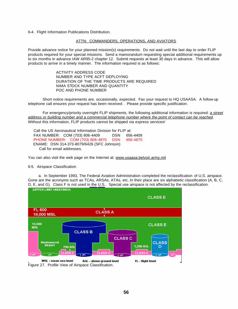
56
6-4. Flight Information Publications Distribution.
ATTN: COMMANDERS, OPERATIONS, AND AVIATORS Provide advance notice for your planned mission(s) requirements. Do not wait until the last day to order FLIP products required for your special missions. Send a mamorandum requesting special additional requirements up to six months in advance IAW AR95-2 chapter 12. Submit requests at least 30 days in advance. This will allow products to arrive in a timely manner. The information required is as follows:
ACTIVITY ADDRESS CODE NUMBER AND TYPE ACFT DEPLOYING
DURATION OF THE TIME PRODUCTS ARE REQUIRED NIMA STOCK NUMBER AND QUANTITY POC AND PHONE NUMBER
Short notice requirements are, occasionally, expected. Fax your request to HQ USAASA. A follow-up
telephone call ensures your request has been received . Please provide specific justification.
For emergency/priority overnight FLIP shipments, the following additional information is required: a street address or building number and a commercial telephone number where the point of contact can be reached. Without this information, FLIP products cannot be shipped via express services!
Call the US Aeronautical Information Division for FLIP at: FAX NUMBER: COM (703) 806-4409 DSN 656-4409 PHONE NUMBER: COM (703) 806-4870 DSN 656-4870
ENAME: DSN 314-373-8079/6426 (SFC Johnson) Call for email addresses. You can also visit the web page on the Internet at: www.usaasa.belvoir.army.mil 6-5. Airspace Classification a. In September 1993, The Federal Aviation Administration completed the reclassification of U.S. airspace. Gone are the acronyms such as TCAs, ARSAs, ATAs, etc..In their place are six alphabetic classification (A, B, C, D, E, and G). Class F is not used in the U.S.. Special use airspace is not affected by the reclassification.
Figure 27. Profile View of Airspace Classification.
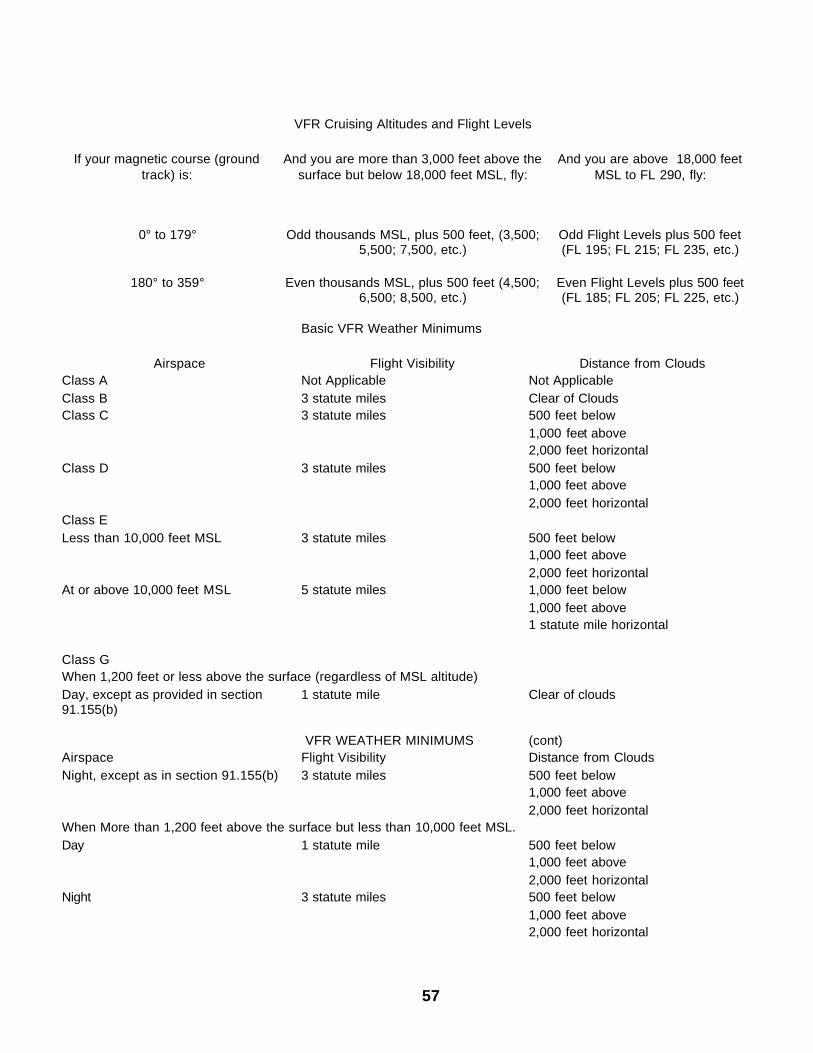
57
VFR Cruising Altitudes and Flight Levels
If your magnetic course (ground track) is:
And you are more than 3,000 feet above the surface but below 18,000 feet MSL, fly:
And you are above 18,000 feet MSL to FL 290, fly:
0° to 179° Odd thousands MSL, plus 500 feet, (3,500;
5,500; 7,500, etc.) Odd Flight Levels plus 500 feet (FL 195; FL 215; FL 235, etc.)
180° to 359° Even thousands MSL, plus 500 feet (4,500;
6,500; 8,500, etc.) Even Flight Levels plus 500 feet (FL 185; FL 205; FL 225, etc.)
Basic VFR Weather Minimums
Airspace Flight Visibility Distance from Clouds Class A Not Applicable Not Applicable Class B 3 statute miles Clear of Clouds Class C 3 statute miles 500 feet below 1,000 feet above 2,000 feet horizontal Class D 3 statute miles 500 feet below 1,000 feet above 2,000 feet horizontal Class E Less than 10,000 feet MSL 3 statute miles 500 feet below 1,000 feet above 2,000 feet horizontal At or above 10,000 feet MSL 5 statute miles 1,000 feet below 1,000 feet above 1 statute mile horizontal Class G When 1,200 feet or less above the surface (regardless of MSL altitude) Day, except as provided in section 91.155(b)
1 statute mile Clear of clouds
VFR WEATHER MINIMUMS (cont) Airspace Flight Visibility Distance from Clouds Night, except as in section 91.155(b) 3 statute miles 500 feet below 1,000 feet above 2,000 feet horizontal When More than 1,200 feet above the surface but less than 10,000 feet MSL. Day 1 statute mile 500 feet below 1,000 feet above 2,000 feet horizontal Night 3 statute miles 500 feet below 1,000 feet above 2,000 feet horizontal

58
More than 1,200 feet above the surface and at or above10,000 feet MSL 5 statute miles 1,000 feet below 1,000 feet above 1 statute mile horizontal
59
CHAPTER 7- DEFINITIONS
AIRPORT WAYPOINT (WP) - A waypoint located on the final approach course at or abeam the first usable landing surface, which is used for construction of the final approach area for an RNAV circling-only approach. ALONGTRACK DISTANCE (ATD) FIX - The ADT fix is an alongtrack position defined as a distance in NM, with reference to the next waypoint. ALTERNATE AERODROME (ICAO) - An aerodrome specified in the flight plan to which a flight may proceed when it becomes inadvisable to land at the aerodrome of intended landing. ALTERNATE AIRFIELD (JCS, NATO) - An airfield specified in the flight plan to which a flight may proceed when a landing at the intended destination becomes inadvisable. An alternate airfield may be the airfield of departure. ALTERNATE AIRPORT (P / CG) - An airfield at which an aircraft may land if a landing at the intended airport becomes inadvisable. APPROACH CLEARANCE - Authorization by Air Traffic Control (ATC) for a pilot to conduct an instrument approach. The type of instrument approach for which cleared and other pertinent information is provided in the approach clearance when required. AREA NAVIGATION / RNAV (P / CG) - A method of navigation that permits aircraft operations of any desired course within the coverage of station- referenced navigation signals or within the limits of self- contained system capability. Random Area Navigation routes, based on area navigation capability, between waypoints defined in terms of latitude / longitude coordinates, degree / distance fixes, or offsets from published or established routes / airways at a specified distance and direction. Major types of equipment are: (1) VORTAC referenced or Course Line Computer (CLC) systems, which account for the greatest number of RNAV units in use. To function, the CLC must be within the service range of the VORTAC.
(2) OMEGA / VLF, although two separate systems, can be considered as one operationally. A long-range navigation system based upon Very Low Frequency radio signals transmitted from a total of 17 stations worldwide. (3) INERTIAL (INS) systems which are totally self-contained and require no information from external references. They provide aircraft position and navigation information in response to signals resulting from inertial effects on components within the system. (4) MLS Area Navigation (MLS/RNAV), which provides area navigation with reference to an MLS ground facility. (5) LORAN-C is a long-range radio navigation system that uses ground waves transmitted at low frequency to provide user position information at ranges of up to 600 to 1,200 nautical miles at both enroute and approach altitudes. The usable signal coverage areas are determined by the signal-to-cycle ratio, the envelope-to cycle difference, and the geometric relationship between the positions of the user and the transmitting stations. AREA NAVIGATION/RNAV (ICAO)- A method of navigation which permits aircraft operation on any desired flight path within the coverage of station-referenced navigation aids or within the limits of the capability of self-contained aids or a combination of these. APPROACH SEQUENCE (P/CG)- The order in which aircraft are positioned while on approach or awaiting approach clearance. BELOW MINIMUMS- Weather conditions below the minimums prescribed by regulations or the particular action involved, e.g., landing minimums, takeoff minimums. CEILING (P/CG)- The height above the earth’s surface of the lowest layer of clouds or obscuring phenomena that is reported as “broken,” “overcast,” or “obscuration,” and not classified as “thin,” or “partial.”
60
CIRCLE TO LAND MANEUVER / CIRCLING MANEUVER- A maneuver initiated by the pilot to align the aircraft with a runway for landing when a straight-in landing from an instrument approach is not possible or is not desirable. This maneuver is made only after ATC authorization has been obtained and the pilot has established required visual reference to the airport. CIRCLE TO RUNWAY (RUNWAY NUMBER)- Used by ATC to inform the pilot that he must circle to land because the runway in use is other than the runway aligned with the instrument approach procedure. When the direction of the circling maneuver in relation to the airport/runway is required, the controller will state the direction (eight cardinal compass points) and specify a left or right downwind or base leg as appropriate, e.g., “Cleared VOR runway 36 approach, circle to runway 22” or “Circle northwest of the airport for a right downwind to runway 22.” CLEARANCE LIMIT (P/CG)- The fix, point, or location to which an aircraft is cleared when issued an air traffic clearance. CLEARED FOR (Type of) APPROACH- ATC authorization for an aircraft to execute a specific instrument approach to an airport, e.g., “Cleared for ILS runway 36 approach.” (See instrument approach clearance.) (Refer to FAR Part 91). CLEARED FOR APPROACH- ATC authorization for an aircraft to execute any standard or special instrument approach procedure for that airport. Normally, an aircraft will be cleared for a specific instrument approach procedure. COMMON TRAFFIC ADVISORY FREQUENCY/CTAF (NIMA)- A frequency designed for the purpose of carrying out airport advisory practices while operating to or from an uncontrolled airport. The CTAF may be a UNICOM, MULTICOM, FSS, or tower frequency and is identified in appropriate aeronautical publications. DEAD RECKONING- The estimating or determining of position by advancing an earlier known position by the application of direction and speed data.
DECISION ALTITUDE/DA (NATO)- An altitude related to the highest elevation in the touchdown zone, specified for a glideslope approach, at which a missed approach procedure must be initiated if the required visual reference has not been established. (See also DECISION HEIGHT) DECISION HEIGHT/DH (P/CG)- With respect to the operation of aircraft means, height at which a decision must be made, during an ILS, MLS or PAR instrument approach, to either continue the approach or to execute a missed approach. DECISION HEIGHT (NATO)- A height in MSL above the highest elevation in the touchdown zone, specified for a glideslope approach, at which a missed approac h procedure must be initiated if the required visual reference has not been established. DECISION HEIGHT/DH (ICAO)- A specified height at which a missed approach must be initiated if the required visual reference to continue the approach to land has not been established. DME ARC- A course, indicated as a constant DME distance, around a navigational facility which provides distance information. DME DISTANCE- The line-of-site distance (slant range) from the source of the DME signal to the receiving antenna. DEPARTURE PROCEDURES (DP)- A preplanned instrument flight rule (IFR) ATC departure procedure published for pilot use in graphic and/or textual form. DPs provide transition form the terminal to the appropriate enroute structure. FINAL APPROACH COURSE- A published MLS course, a straight line extension of a localizer, a final approach radial/bearing, or a runway centerline, all without regard to distance. FINAL APPROACH FIX (FAF)- The fix from which the final approach (IFR) to an airport is executed and which identifies the beginning of the final approach segment. It is denoted on government (DOD and NOS) charts by the Maltese Cross symbol for nonprecision approaches. The Lightning Bolt symbol is used for precision approaches to designate the
61
approximate point where glideslope/path is intercepted at published intercept altitude. FINAL APPROACH POINT (FAP)- The point, applicable only to a non-precision approach with no depicted FAF (such as an on-airport VOR), where the aircraft is established inbound on the final approach course from the procedure turn and where the final approach descent may be commenced. The FAP serves as the FAF and identifies the beginning of the final approach segment. FINAL APPROACH WAYPOINT (FAWP)- A fly-by waypoint that marks the beginning of final approach segment. FIX (P/CP)- A geographical position determined by a visual reference to the surface, by reference to one or more radio NAVAIDS, by celestial plotting, or by another navigational device. GLS - The acronym for Global Navigation Satellite System (GNSS) Landing System GLIDESLOPE/INTERCEPT ALTITUDE- The minimum altitude of the intermediate approach segment prescribed for a precision which assures required obstacle clearance. It is depicted on instrument approach procedure charts. HEIGHT ABOVE AIRPORT (HAA)- The height of the Minimum Descent Altitude above the published airport elevation. This is published in conjunction with circling minimums. HEIGHT ABOVE LANDING (HAL)- The height above a designated helicopter landing area used for helicopter instrument approach procedures. HEIGHT ABOVE SURFACE (HAS) (TERPS)- The height of the MDA above the highest terrain/surface within a 5200 feet radius of the MAP in Point in Space procedures. (Helicopter only procedures) HEIGHT ABOVE TOUCHDOWN (HAT)- The height of the Decision Height or Minimum Descent Altitude above the highest runway elevation in the touchdown zone (First 3000 feet of the runway). HAT is published on instrument approach charts in conjunction with all straight-in minimums.
INITIAL APPROACH WAYPOINT (IAWP)- Normally a fly-by waypoint that marks the beginning of the initial segment and end of the feeder, if applicable. INTERMEDIATE WAYPOINT (IWP)- A fly-by waypoint that marks the end of an initial segment and the beginning of the ntermediate segment. INSTRUMENT APPROACH PROCEDURE (IAP) (P/CG)- A series of predetermined maneuvers for the orderly transfer of an aircraft under instrument flight conditions from the beginning of the initial approach to a point from which a landing may be made visually. It is prescribed and approved for a specific airport by competent authority. (1) US civil standard instrument approach procedures are approved by the FAA as prescribed under FAR Part 97, and are available for public use. (2) US military standard instrument approach procedures are approved and published by the Department of Defense (DOD). (3) Special instrument approach procedures are approved by the FAA for individual operators, but are not published in FAR Part 97, and are not available for public use. INSTRUMENT APPROACH PROCEDURES (NATO), ICAO)- A series of predetermined maneuvers for the orderly transfer of an aircraft under instrument flight conditions from the beginning of the initial approach to a landing, or a point from which a landing may be made visually. INSTRUMENT APPROACH WAYPOINT- Fixes used in defining RNAV instrument approach procedures, including the feeder waypoint (FWP), the initial approach waypoint (IAWP), the intermediate waypoint (IWP), the final approach waypoint (FAWP), the runway waypoint (RWY WP), and the airport waypoint (APT WP), when required. LNAV - LNAV means lateral navigation. A function of RNAV equipment which calculates, displays, and provides horizontal guidance to a profile or path. Note: use of the word horizontal in lieu of lateral. This was used as LNAV affects
62
the entire horizontal plane and to avoid the interpretation of lateral as meaning to the left or right of the profile and/or path. LANDING MINIMUMS (IFR)- The minimum visibility prescribed for landing a civil aircraft while using an instrument approach procedure. The minimum applies with other limitations set forth in FAR Part 91, with respect to the Minimum Descent Altitude (MDA) or Decision Height (DH) prescribed in the instrument approach procedures as follows. (1) Straight-in Landing Minimums- A statement of MDA and visibility, or DH and visibility, required for straight-in landing on a specified runway; or (2) Circling minimums- A statement of MDA and visibility required for the circle-to-land maneuver. Descent below the established MDA or DH is not authorized during an approach unless the aircraft is in a position from which a normal approach to the runway of intended landing can be made, and adequate visual reference to required visual cues is maintained. MINIMUM DECENT ALTITUDE (MDA) (P/CG)- The lowest altitude, expressed in feet above mean sea level to which descent is authorized on final approach or during a circle-to-land maneuver in execution of a standard instrument approach procedure where no electronic glideslope is provided. MINIMUM DESCENT ALTITUDE (NATO)- The lowest altitude to which descent shall be authorized in procedures not using a glideslope, until the required visual reference has been established. MINIMUM HOLDING ALTITUDE (MHA)- The lowest altitude prescribed for a holding pattern which assures navigational signal coverage, communications, and meets obstacle clearance requirements. MINIMUM SAFE ALTITUDE (MSA) (P/CG)- (1) The minimum altitude specified in FAR Part 91, for various aircraft operations. (2) Altitudes depicted on approach charts which provide at least 1000 feet of obstacle clearance for emergency use within a
specified distance from the navigation facility upon which a procedure is predicated. These altitudes will be identified as Minimum Sector Altitudes or Emergency Safe Altitudes and are established as follows. MINIMUM SECTOR ALTITUDES (P/CG)- Altitudes depicted on approach charts which provide at least 1000 feet of obstacle clearance within a 25 nautical mile radius of the navigational facility upon which the procedure is predicated. Sectors depicted on approach charts must be at least 90 degrees in scope. These altitudes are for emergency use only and do not necessarily assure acceptable navigational signal coverage. EMERGENCY SAFE ALTITUDES- Altitudes depicted on approach charts which provide at least 1000 feet of obstacle clearance in non-mountainous areas and 2000 feet of obstacle clearance in designated mountainous areas within a 100 nautical mile radius of the navigation facility upon which the procedure is predicted, and normally used only in military procedures. These altitudes are identified on published procedures as “Emergency Safe Altitudes.” MINIMUM SECTOR ALTITUDE (ICAO)- The lowest altitude which may be used under emergency conditions which will provide a minimum clearance of 300 meters (1000 feet) above all obstacles located in an area contained within a sector of a circle of 25 nautical miles radius centered on a radio aid to navigation. MINIMUM VECTORING ALTITUDE (MVA)- The lowest MSL altitude at which an IFR aircraft will be vectored by a radar controller, except as otherwise authorized for radar approaches, departures, and missed approaches. The altitude meets IFR obstacle clearance criteria. It may be lower than the published MEA along an airway or J-route segment. It may be utilized for radar vectoring only upon the controller’s determination that an adequate radar return is being received from the aircraft being controlled. Charts depicting minimum vectoring altitudes are normally available only to the controllers and not to pilots. (Refer to AIM) MISSED APPROACH (P/CG) (1) A maneuver conducted by a pilot when an instrument approach cannot be
63
completed to a landing. The route of flight an altitude are shone on instrument approach procedure charts. A pilot executing a missed approach prior to the Missed Approach Point (MAP) must continue along the final approach to the MAP. The pilot may climb immediately to the altitude specified in the missed approach procedure. (2) A term used by the pilot to inform ATC that he is executing the missed approach. (3) At locations where ATC radar service provided the pilot should conform to radar vectors, when provided by ATC, in lieu of the published missed approach procedure. MISSED APPROACH POINT (MAP)- A point prescribed in each instrument approach procedure at which a missed approach shall be executed if the required visual reference does not exist. MISSED APPROACH PROCEDURE (NATO, ICAO)- The procedure to be followed if, after an instrument approach, a landing is not effected, and occurring normally: (1) When the aircraft has descended to the decision height and has not established visual contact, or, (2) When directed by air traffic control to pull up or to go around. MISSED APPROACH WAYPOINT- A flyover waypoint used to designate the missed approach point (MAP) and used for construction of the final approach area. POINT IN SPACE APPROACH (COPTER)- In such procedures the point in space and missed approach point are identical and upon arrival at this point, helicopters must proceed under visual flight rules (or Special VFR in control zone as applicable) to a landing area or conduct the specified missed approach procedure. The published procedure shall be noted to this effect and also should identify available landing areas in the vicinity by noting the course and distance from the MAP to each selected landing area. The point in space is located more than 2600 feet from the center of the landing area. PRECISION APPROACH PROCEDURE- A standard instrument approach procedure in
which an electronic glideslope is provided; e.g., ILS, MLS, and PAR. PRECISION APPROACH RADAR (PAR) (P/CG) Radar equipment in some ATC facilities operated by the FAA, and or the military services at joint-use civil/military locations and separate military installations, to detect and display azimuth, elevation, and range of aircraft on the final approach course to a runway. This equipment may be used to monitor certain non-radar approaches, but is primarily used to conduct a precision instrument approach (PAR) wherein the controller issues guidance instructions to the pilot based on the aircraft’s position in relation to the final approach course (azimuth), the glidepath (elevation), and the distance (range) from the touchdown point on the runway as displayed on the radar scope. PROCEDURE TURN (PT) (P/CG)- The maneuver prescribed when it is necessary to reverse direction to establish an aircraft on the intermediate approach segment or final approach course. The outbound course, direction of turn, distance within which the turn must be completed, and minimum altitude are specified in the procedure. However, the point at which the turn may be commenced, and the type and rate of turn, are left to the discretion of the pilot. PROCEDURE TURN INBOUND- The point of a procedure turn maneuver where course reversal has been completed and an aircraft is established inbound on the intermediate approach segment or final approach course. A report of “procedure turn inbound” is normally used by ATC as a position report for separation purposes. REFERENCE FACILITY- A VOR/DME, VORTAC, TACAN facility used for the identification and establishment of an RNAV route, waypoint, or standard instrument approach procedure. RNAV - RNAV is the acronym for area navigation. RNAV provides enhanced navigation capability to the pilot. RNAV equipment can compute the aircraft position, actual track and ground speed and then provide meaningful information relative to a route of flight selected by the pilot.
64
RNAV DECENT ANGLE- A vertical angle defining a descending flight path from the FAWP to the RWY WP. RUNWAY HEADING- The magnetic direction that corresponds with the runway centerline extended, not the painted runway number. When cleared to “fly or maintain runway heading”, pilots are expected to fly or maintain the heading that corresponds with the extended centerline of the departure runway. Drift correction shall not be applied; e.g., if Runway 4 magnetic heading is 044 degrees, fly 044 degrees regardless of wind conditions. RUNWAY WAYPOINT- A waypoint located at the runway threshold and used for construction of the final approach area when the final approach course meets straight-in alignment criteria. SIDESTEP MANEUVER- A visual maneuver accomplished by a pilot at the completion of an instrument approach to permit a straight-in landing on a parallel runway not more than 1200 feet to either side of the runway to which the instrument approach was conducted. STEP-DOWN FIX- A fix permitting additional descent within a segment of an instrument approach procedure by identifying a point at which a controlling obstacle has been safely overflown. STRAIGHT-IN APPROACH (IFR)- A instrument approach wherein final approach is begun without first having to executed a procedure turn. Not necessarily completed with a straight-in landing or made to straight-in landing minimums. SURVEILLANCE APPROACH (ASR) (P/CG)- An instrument approach wherein the air traffic controller issues instructions, for pilot compliance, based on aircraft position in relation to the final approach course (azimuth), and the distance (range), from the end of the runway as displayed on the controller’s radar scope. The controller will provide recommended altitudes on final approach if requested by the pilot. TOUCHDOWN ZONE (P/CG)- The first 3000 feet of the runway beginning at the threshold. The area is used for determination of Touchdown Zone Elevation in the development
of straight-in landing minimums for instrument approaches. TOUCHDOWN ZONE ELEVATION (TDZE)- The highest elevation in the first 3000 feet of the landing surface. TDZE is indicated on the instrument approach procedure chart when straight-in landing minimums are authorized. TRACK (P/CG)- The actual flight path of an aircraft over the surface of the earth. TRANSITION- The general term that describes the change from one phase of flight or flight condition to another, e.g., transition from instrument flight to visual flight. TURN WAYPOINT- A waypoint which identifies a change from one course to another. VNAV - VNAV means vertical navigation. A function of RNAV equipment which calculates, displays, and provides vertical guidance to a profile or path. VISIBILITY (P/CG)- The ability, as determined by atmospheric conditions and expressed in units of distance, to see and identify prominent unlighted objects by day and prominent lighted objects at night. Visibility is reported as statute miles, hundreds of feet or meters. (1) FLIGHT VISIBILITY- The average forward horizontal distance, from the cockpit of an aircraft in flight, at which prominent unlighted objects may be seen and identified by day and prominent lighted objects may be seen at night. (2) GROUND VISIBILITY- Prevailing horizontal visibility near the earth’s surface as reported by the United States National Weather Service or an accredited observer. (3) PREVAILING VISIBILITY - The greatest horizontal visibility equaled or exceeded throughout at least half the horizon circle which need not necessarily be continuous. (4) RUNWAY VISIBILITY VALUE (RVV)- The visibility determined for a particular runway by a transmissometer. A meter provides a continuous indication of the visibility (reported in miles or fraction of miles) for the runway. RVV is used in lieu of prevailing visibility in determining minimums for a particular runway.
65
(5) RUNWAY VISUAL RANGE (RVR)- A instrumentally derived value, based on standard calibrations, that represents the horizontal distance the pilot will see down the runway from the approach end; it is based on the sighting of either high intensity runway lights or on the visual contrast of other targets whichever yields the greater visual range. RVR, in contrast to prevailing or runway visibility, is based on what a pilot in a moving aircraft should see looking down the runway. RVR is horizontal visual range, not slant visual range. It is based on the measurement of a transmissometer made near the touchdown point of the instrument runway and is reported in hundreds of feet. RVR is used in lieu of RVV and/or prevailing visibility in determining minimums for a particular runway.
(a) TOUCHDOWN RVR- The RVR visibility readout values obtained from RVR equipment serving the runway touchdown zone. (b) MID RVR- The readout values obtained from RVR equipment located midfield of the runway. (c) ROLLOUT RVR- The RVR readout values obtained from RVR equipment located nearest the rollout end of the runway. WAYPOINT (P/CG)- A predetermined geographical position used for route instrument approach definition, or progress reporting purposes, that is defined relative to a VORTAC station or in terms of Latitude/Longitude coordinates.
By Order of the Secretary of the Army:
ERIC K. SHINSEKI General, United States
Army Chief of Staff
Official
Administrative Assistant to the Secretary of the Army 0100302