spacewire user’s guide - star-dundee
TRANSCRIPT

iopasdfghjklzxcvbnmq

2

3
SpaceWire User’s Guide
Steve Parkes

4

5
Copyright © 2012 STAR-Dundee Limited
All rights reserved. No part of this book may be reproduced in any form
without permission.
ISBN: 978-0-9573408-0-0
Published by STAR-Dundee Limited, 2012

6

7
Table of Contents
GLOSSARY 10
1 INTRODUCTION 12
2 THE SPACEWIRE DATA-HANDLING NETWORK 13
2.1 The Rationale for and Brief History of SpaceWire 13
2.2 An Example SpaceWire Application 15
2.3 How SpaceWire Works 17 2.3.1 SpaceWire Links 17 2.3.2 SpaceWire Packets 18
2.4 SpaceWire Architectures 22 2.4.1 Point to Point Links 22 2.4.2 Fault Tolerant Links 24 2.4.3 Router Based Architecture 26 2.4.4 Instrument Data Concentrator 31 2.4.5 Bridge to Low Data Rate Sensor Bus 32
2.5 Example SpaceWire Mission Architectures 33 2.5.1 Missions Using SpaceWire 33 2.5.2 ESA ExoMars 36 2.5.3 NASA Lunar Reconnaissance Orbiter 38 2.5.4 BepiColombo 40 2.5.5 ASNARO 43
3 SPACEWIRE LINKS 45
3.1 Physical Level 46 3.1.1 Cables 46 3.1.2 Connectors 47 3.1.3 Cable Assemblies 47 3.1.4 Printed Circuit Board Tracks 49
3.2 Signal Level 49 3.2.1 Signal Level and Noise Margins 49 3.2.2 Data encoding 52
3.3 Character Level 53 3.3.1 SpaceWire Characters 53 3.3.2 Parity Coverage 55

8
3.3.3 Character Priority 56 3.3.4 Character Functions 56 3.3.5 Character Synchronisation 57
3.4 Exchange Level 58 3.4.1 SpaceWire Link Interface 58 3.4.2 Link Initialisation 60 3.4.3 Link Flow Control 65 3.4.4 Link Error Handling 67 3.4.5 Auto-Start 70
3.5 Packet Level 71
3.6 Link error Recovery 73
4 SPACEWIRE NETWORKS 77
4.1 SpaceWire Nodes 77
4.2 SpaceWire Routing Switch 77
4.3 Routing Tables 78
4.4 Group Adaptive Routing 81
4.5 Wormhole Routing 82
4.6 Header Deletion 84
4.7 Time-code Broadcast 87
4.8 Router Configuration 88
4.9 Packet Distribution 88
4.10 Example SpaceWire Router 88 4.10.1 SpW-10X Architecture 88 4.10.2 Watchdog Timers 91 4.10.3 Routing to a Not-Connected Port 91 4.10.4 Routing to a Non-Existent Port 91 4.10.5 Routing to a Busy Port 91 4.10.6 Start On Request, Disable On Silence 92 4.10.7 Tristate 95 4.10.8 Disable Transmit Clocks 95 4.10.9 Priority Packet Delivery 95
5 TIME-CODES 97
5.1 Time-code Structure 97
5.2 Time-code Interface 97

9
5.3 Time-counter 98
5.4 Time Master 99
5.5 Time-codes across a Link 99
5.6 Router Action on Receiving a Time-code 100
5.7 Time-code Distribution across a Network 100
5.8 Lost Time-Codes 103
5.9 Time-code Latency 105
5.10 Time-code Applications 106 5.10.1 Synchronisation 106 5.10.2 Time Distribution 106 5.10.3 Event Signalling Across A Point-To-Point Link 106 5.10.4 Multiple Time-codes 107 5.10.5 Interrupt scheme 107
6 SPACEWIRE PROTOCOLS 108
6.1 Protocol Identifier 108
6.2 Remote Memory Access Protocol 108
6.3 CCSDS Packet Transfer Protocol 109
REFERENCES 110
10
GLOSSARY
Data character – A character containing 8-bits of data
Destination
address
– The leading byte or bytes of a packet that are used
by routers to determine how to route a packet
towards its destination
EEP – Error End of Packet, which is used to terminate a
packet when an error has occurred
EOP – End of Packet marker which indicates the end of a
packet
FCT – Flow Control Token which is exchanged for eight N-
Chars
Input port – The part of a SpaceWire interface in a router that
receives packets
Link – A connection between two SpaceWire interfaces
N-Char – A data character, EOP, or EEP
Node – A source or destination of SpaceWire packets
Null – A symbol that is sent when there is no other
information to send to keep the link active
Output port – The part of a SpaceWire interface in a router that
sends packets
Packet – A sequence of data characters followed by an EOP
or EEP, the packet is made up of a destination
address, cargo, and EOP/EEP
Port – An input port or output port of a SpaceWire router

11
Router – A packet switch that forwards packets towards their
destination, selecting a link to forward the packet
through based on the destination address of the
packet
SpaceWire
interface
– An interface used to send SpaceWire packets and
time-codes
Time-code – A symbol comprising an Escape symbol followed by a
data character, where the data character contains
two reserved bits and six bits of time information

12
1 Introduction
The SpaceWire User’s Guide aims to introduce the reader to SpaceWire.
It begins in chapter 2 with an overview of SpaceWire, providing a brief
history of SpaceWire, looking at an example SpaceWire application,
examining how SpaceWire works, considering different SpaceWire
architectures, and finally looking at some real mission architectures to see
how SpaceWire is being used in practice.
Section 3 goes into much more detail about SpaceWire links. It describes
each level of the SpaceWire standard in detail, explaining the way each
level operates and the reasons SpaceWire is designed the way it is.
Section 4 describes SpaceWire routers and networks. SpaceWire nodes
and routers are introduced and the mechanism inside a router explained
along with the way in which a router is configured. An example SpaceWire
router chip, the Atmel AT7910E SpW-10X router, is then described in some
detail.
Section 5 explains how SpaceWire time-codes work and introduces some of
the applications they have been used for.
Section 6 introduces some higher level SpaceWire protocols. This chapter is
yet to be completed. Please check www.star-dundee.com for the latest
version.
The SpaceWire User's Guide is compiled from several papers written by
Steve Parkes, the CEO of STAR-Dundee and author of this guide.

13
2 The SpaceWire Data-Handling Network
SpaceWire is a data-handling network for use on-board spacecraft, which
connects together instruments, mass-memory, processors, downlink
telemetry, and other on-board sub-systems [1] [2] [3]. SpaceWire is simple
to implement and has some specific characteristics that help it support data-
handling applications in space: high-speed, low-power, simplicity, relatively
low implementation cost, and architectural flexibility making it ideal for many
space missions. SpaceWire provides high-speed (2 Mbits/s to 200 Mbits/s),
bi-directional, full-duplex data-links, which connect together SpaceWire
enabled equipment. Data-handling networks can be built to suit particular
applications using point-to-point data-links and routing switches.
Since the SpaceWire standard was published in January 2003, it has been
adopted by ESA, NASA, JAXA and RosCosmos for many missions and is
being widely used on scientific, Earth observation, commercial and other
spacecraft. High-profile missions using SpaceWire include: Gaia, ExoMars
rover, BepiColombo, James Webb Space Telescope, GOES-R, Lunar
Reconnaissance Orbiter and Astro-H.
2.1 The Rationale for and Brief History of SpaceWire
Before SpaceWire became a standard, many spacecraft primes and
equipment manufacturers had their own proprietary communication interface
for inter-unit communications, e.g. connecting high data-rate instruments to
mass-memory units. This resulted in several different communication links
being used on a spacecraft, increasing the cost and extending the time
required for spacecraft integration and test. There was a clear need for a
standard on-board communication link that would simplify spacecraft
development.
Back in 1992, when work on what became SpaceWire started, there was
also substantial interest in high performance digital signal processing
systems which were beyond the capability of the single-chip devices

14
available at that time. The use of parallel processing was investigated and
this required some form of network to interconnect the individual processing
elements [4]. The Inmos Transputer [5], a microprocessor designed for
parallel processing was studied, and the serial communication links being
developed for the T9000 Transputer [6] were identified as being an
attractive solution for spacecraft on-board networking. This serial link
technology was subsequently published as IEEE 1355-1995 [7].
Several radiation tolerant devices were developed using the IEEE 1355-
1995 standard and it was used on some space missions. However, there
were many problems with this standard, which had to be resolved if this
technology was to continue to be used for ESA spacecraft. University of
Dundee received a contract from ESA [8] to examine and solve these
problems which eventually resulted in the SpaceWire standard.
SpaceWire aims to:
facilitate the construction of high-performance on-board data-
handling systems,
help reduce system integration costs,
promote compatibility between data-handling equipment and
subsystems, and
encourage re-use of data-handling equipment across several
different missions.
Use of the SpaceWire standard ensures that equipment is compatible at
both the component and sub-system levels. Instruments, processing units,
mass-memory devices and down-link telemetry systems using SpaceWire
interfaces developed for one mission can be readily used on another
mission. This:
reduces the cost of development (Cheaper),
reduces development timescales (Faster),
improves reliability (Better),
increases the amount of scientific work that can be achieved within
a limited budget (More).
15
2.2 An Example SpaceWire Application
SpaceWire is able to support many different payload processing
architectures using point-to-point links and SpaceWire routing switches. The
data-handling architecture can be constructed to suit the requirements of a
specific mission, rather than having to force the application onto a restricted
bus or network with restricted topology.
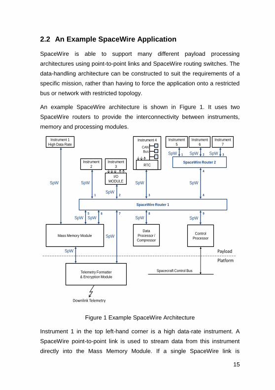
An example SpaceWire architecture is shown in Figure 1. It uses two
SpaceWire routers to provide the interconnectivity between instruments,
memory and processing modules.
Instrument 1
High Data Rate
SpaceWire Router 1
Control
Processor
Data
Processor /
Compressor
SpW
SpW SpW
Instrument
2
SpW
SpW
Mass Memory Module
SpW
SpW
SpaceWire Router 2
SpW SpW SpW
Telemetry Formatter
& Encryption Module
SpW
SpW
I/O
MODULE SpW
Instrument 4
Instrument
3
Instrument
5
Instrument
6
Instrument
7
Spacecraft Control Bus
RTC
CAN
Bus
SpW
1 2 3 4
98765
1 2 3
4
Platform
Payload
Downlink Telemetry
Figure 1 Example SpaceWire Architecture
Instrument 1 in the top left-hand corner is a high data-rate instrument. A
SpaceWire point-to-point link is used to stream data from this instrument
directly into the Mass Memory Module. If a single SpaceWire link is
16
insufficient to handle the data-rate from this instrument then two or more
links may be used in parallel.
Instrument 2 is of lower data-rate than instrument 1. Its data is passed
though SpaceWire Router 1 to the Mass Memory Module.
Instrument 3 does not have a SpaceWire interface so an input/output (I/O)
module is used to connect the instrument to the SpaceWire router. Its data
may then be sent over the SpaceWire network to the Mass Memory Module.
Instrument 4 is a complex instrument containing a number of sub-modules
which are interconnected using the CAN bus. A Remote Terminal Controller
(RTC) is used to bridge between the CAN bus and SpaceWire. Other
signals from the instrument are also connected to the RTC, which contains a
processor for performing the bridging and local instrument control functions.
Instruments 5, 6 and 7 are located in a remote part of the spacecraft. To
avoid having three SpaceWire cables running to this remote location a
second router (SpaceWire Router 2) is used to concentrate the information
from these three instruments and send it over a single SpaceWire link to
Router 1 and then on to the Mass Memory Module.
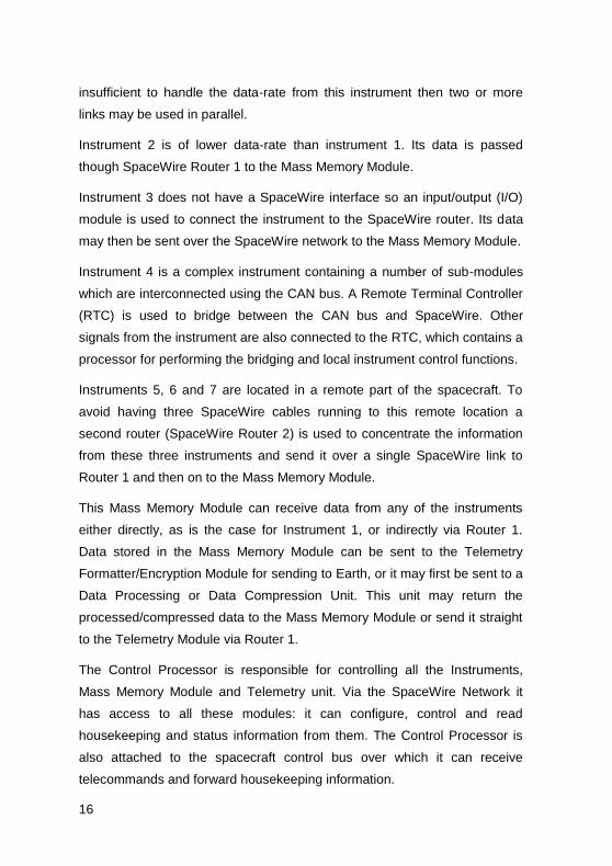
This Mass Memory Module can receive data from any of the instruments
either directly, as is the case for Instrument 1, or indirectly via Router 1.
Data stored in the Mass Memory Module can be sent to the Telemetry
Formatter/Encryption Module for sending to Earth, or it may first be sent to a
Data Processing or Data Compression Unit. This unit may return the
processed/compressed data to the Mass Memory Module or send it straight
to the Telemetry Module via Router 1.
The Control Processor is responsible for controlling all the Instruments,
Mass Memory Module and Telemetry unit. Via the SpaceWire Network it
has access to all these modules: it can configure, control and read
housekeeping and status information from them. The Control Processor is
also attached to the spacecraft control bus over which it can receive
telecommands and forward housekeeping information.
17
With several instruments and the Data Processor/Compressor sending data
to the Mass Memory Module via Router 1, a single link from that Router to
the Mass Memory Module may be insufficient to handle all the data, so a
second link has been added to provide more bandwidth. In a SpaceWire
network links can be added to provide additional bandwidth or to add fault
tolerance to the system. In Figure 1 no redundancy has been included for
clarity. In a spaceflight application, an additional pair of routers would be
included with duplicate links to the modules to provide redundancy. It is
straightforward to support traditional cross-strapped, redundant modules
using SpaceWire.
2.3 How SpaceWire Works
Having looked at the way in which SpaceWire can be used to provide a
spacecraft data-handling system, we will now examine SpaceWire in a little
more detail to provide some understanding of how SpaceWire works.
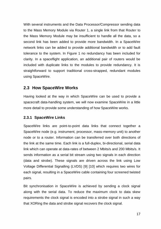
2.3.1 SpaceWire Links
SpaceWire links are point-to-point data links that connect together a
SpaceWire node (e.g. instrument, processor, mass-memory unit) to another
node or to a router. Information can be transferred over both directions of
the link at the same time. Each link is a full-duplex, bi-directional, serial data
link which can operate at data-rates of between 2 Mbits/s and 200 Mbits/s. It
sends information as a serial bit stream using two signals in each direction
(data and strobe). These signals are driven across the link using Low
Voltage Differential Signalling (LVDS) [9] [10] which requires two wires for
each signal, resulting in a SpaceWire cable containing four screened twisted
pairs.
Bit synchronisation in SpaceWire is achieved by sending a clock signal
along with the serial data. To reduce the maximum clock to data skew
requirements the clock signal is encoded into a strobe signal in such a way
that XORing the data and strobe signal recovers the clock signal.

18
Character synchronisation is performed once only, when the link is started.
If character synchronisation is ever lost it will be detected as a parity error
and the link restarted to recover character synchronisation.
SpaceWire provides a simple mechanism for starting a link, keeping the link
running, sending data over the link, ensuring that data is not sent if the
receiver at the other end of the link is not ready for it, and for recovering
from any errors on the link. All this is handled by the link state-machine in
the SpaceWire interface and is transparent to the user application.
2.3.2 SpaceWire Packets
Information is transferred across a SpaceWire link in distinct packets.
Packets can be sent in both directions of the link, provided that there is
room in the receiver for more data.
A packet is formatted as illustrated in Figure 2.
Destination Address Cargo EOP
Figure 2 SpaceWire Packet Format
The "Destination Address" is the first part of the packet to be sent and is a
list of data characters that represents either the identity of the destination
node or the path that the packet has to take through a SpaceWire network
to reach to the destination node. In the case of a point-to-point link directly
between two nodes (no routers in between) the destination address is not
necessary.
The "Cargo" is the data to be transferred from source to destination. Any
number of data bytes can be transferred in the cargo of a SpaceWire
packet.

19
The “End of Packet” (EOP) is used to indicate the end of a packet. The data
character following an EOP is the start of the next packet. There is no limit
on the size of a SpaceWire packet.
As can be seen, the packet format for SpaceWire is very simple. It is,
however, also very powerful, allowing SpaceWire to be used to carry a
range of user protocols, with minimal overhead.
2.3.2.1 SpaceWire Networks
SpaceWire networks are constructed using SpaceWire point-to-point links
and routing switches.
2.3.2.2 SpaceWire Routing Switches
A SpaceWire router [11] connects together many nodes using SpaceWire
links, providing a means of routing packets from one node to any of the
other nodes or routers attached to the router. A node is simply the source or
destination of a SpaceWire packet. A SpaceWire router comprises a number
of SpaceWire link interfaces and a switch matrix. The switch matrix enables
packets arriving at one link interface to be transferred to and sent out of
another link interface on the router.
Each link interface may be considered as comprising an input port (the link
interface receiver) and an output port (the link interface transmitter). A
SpaceWire router transfers packets from the input port of the switch where
the packet arrives, to a particular output port determined by the packet
destination address. A router uses the leading data character of a packet
(one of the destination address characters) to determine the output port of
the router to which the packet is to be routed. If there are two input ports
waiting to use a particular output port when the previous packet has finished
being sent, an arbitration mechanism decides which input port is to be
served.

20
2.3.2.3 Packet Addressing
The destination address at the front of a SpaceWire packet is used to route
the packet through a network from the source node to the destination. There
are two forms of addressing used in SpaceWire networks: path addressing
and logical addressing.
Path addressing can best be understood using the simple analogy of
providing directions to someone driving a car. To reach the destination you
might suggest that the driver takes exit 2 at the first roundabout, exit 1 at the
next roundabout, and finally exit 3 on the third roundabout. The driver will
then have reached the required destination (see Figure 3). There is a
direction to follow at each roundabout (take a particular exit). Together these
directions describe the path from the initial position to the required
destination. There is a list of directions to follow, one for each roundabout.
Once a direction has been followed it is crossed off the list and the next
direction is followed at the next roundabout.
In a SpaceWire network the roundabouts are routers and the roads
connecting the roundabouts are the links connecting the routers (see Figure
3). The list of directions is attached to the front of the SpaceWire packet
forming the destination address. The first direction is followed when the first
router is encountered. This direction is simply a data character that specifies
which port of the router the packet should be forwarded through. A router
can have a maximum of 31 external ports (port numbers 1 to 31) and one
internal configuration port (port number 0). The leading data character at the
front of the packet is used to specify the port that the packet is to be
forwarded through: if the leading data character is 3, the packet will be
forwarded out port 3 of the router. Once the leading data character has been
used to forward a packet, it is discarded as it is no longer needed. This
reveals the next data character in the path address for routing the packet at
the next router. Figure 3, shows how the path address at the start of the
packet is modified as the packet goes through the network. Since a router

21
can have a maximum of 31 ports along with an internal configuration port,
each data character forming a path address is in the range 0 to 31.
SpaceWire
Router 1
Source
1
5
4
2
3
4
Destination
SpaceWire
Router 21
2
3SpaceWire
Router 32
4
3
4
1
<2,1,3><Cargo><EOP>
<1,3><Cargo><EOP>
<3><Cargo><EOP>
<Cargo><EOP>
Figure 3 Path Addressing
Logical addressing can also be understood using the analogy of giving
directions to a car driver. Logical addressing is like saying to the driver,
“follow the signs to Dundee at each of the roundabouts”. This, of course,
requires appropriate signs to be placed at each roundabout and each
destination has to have a name or identifier so that it can be recognised on
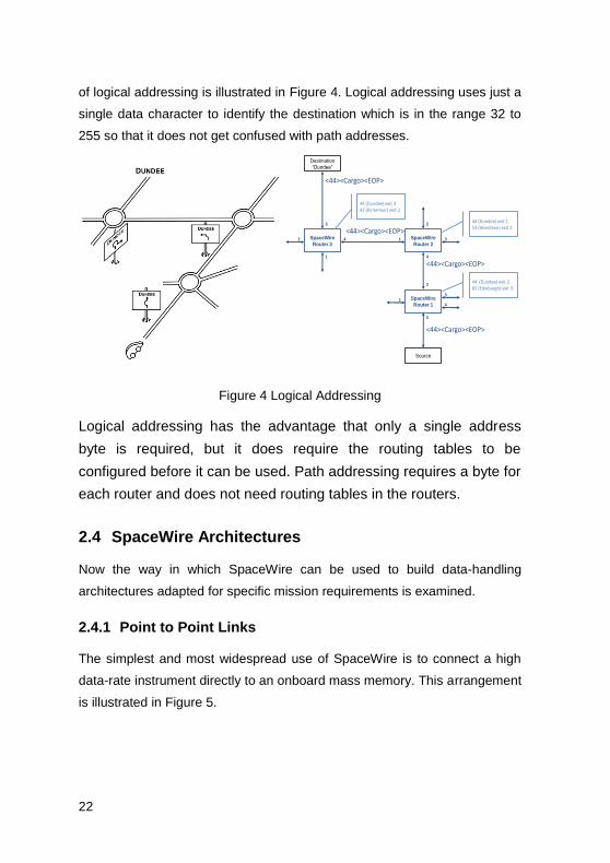
the signs. The logical address analogy is illustrated in Figure 4.
In a SpaceWire network using logical addressing, each destination is given
an identifier, which is a number in the range 32 to 255. Each router in the
network has a routing table (like the sign at a roundabout) which specifies
what port the packet should be forwarded through for each possible
destination identifier. The leading data character of a packet is set to the
required destination identifier (e.g. 44 for Dundee). At each router the
leading data character is used to look up the appropriate directions from the
routing table and the packet is forwarded accordingly. For logical addressing
the leading data character is not discarded at each router, since it will be
needed to look up the path to follow at the next router encountered. The use
22
of logical addressing is illustrated in Figure 4. Logical addressing uses just a
single data character to identify the destination which is in the range 32 to
255 so that it does not get confused with path addresses.
SpaceWire
Router 1
Source
1
5
4
2
3
4
Destination
“Dundee”
SpaceWire
Router 21
2
3SpaceWire
Router 32
3
4
1
<44><Cargo><EOP>
<44><Cargo><EOP>
<44><Cargo><EOP>
<44><Cargo><EOP>
44 (Dundee) exit 265 (Edinburgh) exit 3
44 (Dundee) exit 153 (Aberdeen) exit 2
44 (Dundee) exit 342 (Kirriemuir) exit 2
Figure 4 Logical Addressing
Logical addressing has the advantage that only a single address
byte is required, but it does require the routing tables to be
configured before it can be used. Path addressing requires a byte for
each router and does not need routing tables in the routers.
2.4 SpaceWire Architectures
Now the way in which SpaceWire can be used to build data-handling
architectures adapted for specific mission requirements is examined.
2.4.1 Point to Point Links
The simplest and most widespread use of SpaceWire is to connect a high
data-rate instrument directly to an onboard mass memory. This arrangement
is illustrated in Figure 5.

23
Instrument Memory
SpaceWire
Figure 5 Point to Point Link
The instrument can send SpaceWire packets containing the instrument data
directly to the memory over the SpaceWire link. The data can be packaged
into SpaceWire packets with a size appropriate to the application. For
example if the instrument is some form of push broom imager it may be
appropriate to send one line of the image at a time e.g. 34 KByte packets. If
the instrument is a camera a complete image could be transferred in one
packet e.g. 2 MBytes.
The instrument can simply send data to the memory once it has collected
the data or the memory could send a command to the instrument to ask for
the next set of data. SpaceWire includes low-level flow control so that if the
memory is not ready the instrument is unable to send data until the memory
becomes ready. This means that if the memory is not able to accept data
from the camera as soon as it is ready, the camera will have to buffer the
data.
The advantages of this type of architecture are:
Simplicity
Low power per Mbit/s
Full bandwidth of link available to application
The disadvantages are:
No redundancy – if the link fails the instrument is lost.
May be inefficient if link bandwidth not fully utilised
24
This latter point serves to highlight another capability of SpaceWire. A
SpaceWire interface can initialise very rapidly (20 µs). If an instrument
provides data in bursts or occasionally on demand, then it is possible to turn
off the link when it is not being used. If one end of the link is set to auto-start
mode it will start up as soon as some traffic appears on the link. So, for
example, if the instrument is to send data to the memory occasionally when
it has detected some event, the SpaceWire interface on the memory may be
put into auto-start mode. The SpaceWire interface in the memory will stop
and wait listening for any traffic on its input. The instrument can then switch
off its SpaceWire interface. When an event occurs the SpaceWire interface
in the instrument is enabled and started, the initialisation traffic on the link is
detected by the SpaceWire interface in the memory unit causing its link to
start and a connection to be made. The instrument can then transfer its
data. It takes just 20 µs to achieve this connection.
The type of application where the single point to point link is used is for the
direct connection of an instrument to memory where no fault tolerance is
required i.e. it is acceptable that if the SpaceWire link fails the instrument is
lost.
2.4.2 Fault Tolerant Links
The avoidance of possible single point failures is important for most space
missions especially for mission critical services. SpaceWire provides a
simple means of adding fault tolerance into a system where it is required.
SpaceWire is fairly robust due to the good EMC properties of LVDS and the
cable screening used. Rarely are errors seen on a link unless they are
injected. If a transient error does occur then the SpaceWire link immediately
disconnects itself electrically and goes through the re-initialisation process.
In 20 µs the link is up and running again. The packet that was in the process
of being transferred is truncated and terminated by a special Error End of
Packet (EEP) character to indicate that it was terminated prematurely. The
next packet to be sent will be delivered successfully provided that the fault

25
was temporary. If the packet that was terminated by the fault was important
then it is up to the user application to detect the fact that it was not delivered
properly and to resend the information. Protocols for providing this type of
service which run over SpaceWire have been and are being developed by
the SpaceWire working group.
If the fault on a SpaceWire link is permanent, for example the wires may
have become disconnected or a SpaceWire interface may have stopped
working, then recovery requires a second, redundant SpaceWire link. This is
illustrated in Figure 6.
Instrument Memory
Prime
Redundant
Figure 6 Fault Tolerant Links
If the prime SpaceWire link stops working then the redundant link has to be
started and data sent over this link. Simple logic in the instrument can
provide this functionality.
A more robust system is illustrated in Figure 7.
InstrumentPrime
MemoryPrime
SpaceWire
Prime
Redundant
InstrumentRedundant
MemoryRedundantRedundant
Redundant
Figure 7 Cross-Strapping
In this example the instrument is crucial to the mission success so two
instruments are provided. Each instrument has two SpaceWire interfaces:

26
one prime and one redundant. Similarly there are two memory units. During
normal operation the redundant instrument and memory units are switched
off. The prime instrument sends data to the prime memory. If the prime
instrument fails then it is switched off and the redundant instrument is
switched on. The prime memory then receives instrument data via its
redundant SpaceWire interface. This classical cross-strapping is readily
supported by SpaceWire – additional links are simply put where redundancy
is required.
The advantages of this type of architecture are:
Simplicity
Low power per Mbit/s
Full bandwidth of link available to application
Fault tolerant
The disadvantages are:
Mass penalty as several links needed for redundancy
Inefficient if bandwidth not fully utilised
This architecture is ideal where the direct connection of an instrument to a
memory or other unit is required and where a single point failure is not
acceptable.
It is important that a failure on the prime link does not propagate and cause
a failure on the redundant link.
2.4.3 Router Based Architecture
A SpaceWire router enables more sophisticated architectures to be
implemented when required. A basic router-based architecture is illustrated
in Figure 8.

27
Instrument1
Memory
Instrument2
Processor
Router
Figure 8 Basic Router-Based Architecture
The SpaceWire router interconnects all of the SpaceWire units. It is then
possible for any unit to send data or receive data from another unit. The two
instruments can send data to the memory unit, the processor unit can read
data from the memory unit for checking or processing, and the processor
can control the two instruments and memory unit.
The advantages of this type of architecture are:
Versatile architecture
All units can talk to one another through router
Control and data can be sent over network
Control flow is generally opposite direction to data flow
The disadvantages are:
Have to be aware of potential blocking in router - need to consider
traffic on network
Router is potential single point failure
Additional power consumption of router
28
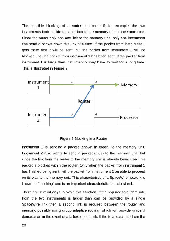
The possible blocking of a router can occur if, for example, the two
instruments both decide to send data to the memory unit at the same time.
Since the router only has one link to the memory unit, only one instrument
can send a packet down this link at a time. If the packet from instrument 1
gets there first it will be sent, but the packet from instrument 2 will be
blocked until the packet from instrument 1 has been sent. If the packet from
instrument 1 is large then instrument 2 may have to wait for a long time.
This is illustrated in Figure 9.
Instrument1
Memory
Instrument2
Processor
Router
1 2
3 4
Figure 9 Blocking in a Router
Instrument 1 is sending a packet (shown in green) to the memory unit.
Instrument 2 also wants to send a packet (blue) to the memory unit, but
since the link from the router to the memory unit is already being used this
packet is blocked within the router. Only when the packet from instrument 1
has finished being sent, will the packet from instrument 2 be able to proceed
on its way to the memory unit. This characteristic of a SpaceWire network is
known as “blocking” and is an important characteristic to understand.
There are several ways to avoid this situation. If the required total data rate
from the two instruments is larger than can be provided by a single
SpaceWire link then a second link is required between the router and
memory, possibly using group adaptive routing, which will provide graceful
degradation in the event of a failure of one link. If the total data rate from the

29
two instruments is less than the data rate of a single SpaceWire link then
the router can act as a concentrator permitting a packet from say instrument
1 first, followed by a packet from instrument 2. In this case the amount of
data buffering in the instruments will depend upon the size of the packets
being sent. Hence, it makes sense to use short packets rather than long
ones to reduce the amount of buffer memory required. Another alternative is
for the memory (or processor) to control when an instrument is allowed to
send data. For example, the memory could request data from instrument 1
and once this has been received it could request data from instrument 2.
There are many possibilities: SpaceWire is flexible enough to support the
requirements of different types of mission.
It should be noted that since the router uses wormhole routing and does not
support packet buffering in the router, the speed of all the SpaceWire links
attached to a router should normally all be set to the same rate.
Typical applications for this type of architecture include payload data-
handling systems with more than one instrument or multiple possible
destinations for data from an instrument. The potential single point failure of
the router can be avoided by including a second router connected to all the
units.
Figure 10 shows a prime and redundant pair of routers which have been
included in prime and redundant data handling units together with the mass
memory and processing units. This provides router redundancy while
reducing the lengths (and hence mass) of the SpaceWire links.

30
Prime
Redundant
Instrument 1Prime
Memory
Instrument 2Prime
ProcessorRouter
Router
Memory
Processor
Instrument 1Redundant
Instrument 2Redundant
Figure 10 Router in Data-Handling Unit
The advantages of this type of architecture are:
Supports multiplexing of several instruments
Supports prime/redundant instruments
No single point failures
Lower mass penalty of links since several links embedded in data-
handling units
The disadvantages are:
Have to be aware of potential blocking in router - need to consider
traffic on network
Additional power consumption of router.
This type of architecture is ideal when a redundant data handling system is
required.
31
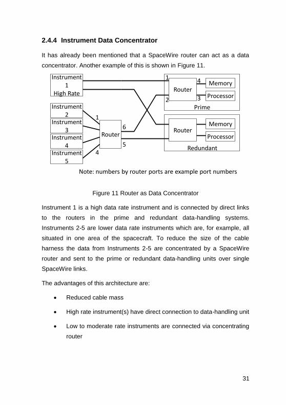
2.4.4 Instrument Data Concentrator
It has already been mentioned that a SpaceWire router can act as a data
concentrator. Another example of this is shown in Figure 11.
Prime
Redundant
Instrument1
High Rate
Memory
Instrument2
ProcessorRouter
RouterMemory
Processor
Instrument3
RouterInstrument4
Instrument5
1
45
6
1
2
4
3
Note: numbers by router ports are example port numbers
Figure 11 Router as Data Concentrator
Instrument 1 is a high data rate instrument and is connected by direct links
to the routers in the prime and redundant data-handling systems.
Instruments 2-5 are lower data rate instruments which are, for example, all
situated in one area of the spacecraft. To reduce the size of the cable
harness the data from Instruments 2-5 are concentrated by a SpaceWire
router and sent to the prime or redundant data-handling units over single
SpaceWire links.
The advantages of this architecture are:
Reduced cable mass
High rate instrument(s) have direct connection to data-handling unit
Low to moderate rate instruments are connected via concentrating
router

32
The disadvantages of the particular architecture shown in Figure 11 are:
Have to be aware of potential blocking in router - need to consider
traffic on network
Concentrating router is not redundant
The concentrating router can be made redundant if required by adding
redundant SpaceWire links and interfaces.
This type of architecture is suitable for payload data-handling systems with
distributed clusters of instruments which are being served by centralised
data-handling unit.
2.4.5 Bridge to Low Data Rate Sensor Bus
Some sensors, like thermocouples, are very low data rate and a low data
rate sensor bus (e.g. CAN bus) may be more suitable for gathering data
from them. The data gathered may still be sent to the data-handling system
via a SpaceWire link if a bridge between the low data rate sensor bus and
SpaceWire is used. This is illustrated in Figure 12.
Prime
Redundant
Instrument1
High Rate
Memory
Instrument2
ProcessorRouter
RouterMemory
Processor
Instrument3
Router
Instrument4
SensorA
RTCSensor
BSensor
C
Low Data Rate Bus
Figure 12 Bridge to Low Data Rate Bus
33
The Remote Terminal Computer (RTC) provides a bridge between the
SpaceWire network and the low data rate sensor bus. The RTC gathers
data from the low data rate sensors, puts it in a SpaceWire packet and
sends it to the data handling system. Commands for the low data rate
sensors (or actuators) can be passed from the data-handling processor to
the RTC for distribution to the low data rate sensors.
The advantages of this type of network are:
Multiple low data rate sensors attached to low speed bus - sensor
data packed and sent to data-handling unit over SpaceWire
Legacy devices can be supported – e.g. Mil-Std 1553
The disadvantages are:
Two types of bus/network used
The applications for this type of architecture are data handling systems that
include several low data rate sensors or that require to support legacy
devices.
Other units like the downlink telemetry and uplink telecommand system can
be readily included in a SpaceWire system. SpaceWire architectures can be
adapted to the mission requirements including links to serve one or more
instruments, routers to provide architectural flexibility, and interfaces to
electronic ground support equipment.
2.5 Example SpaceWire Mission Architectures
Some of the major space missions currently using SpaceWire are listed in
this section and then the data-handling architectures of five of them (two
from ESA, one from NASA, and two from JAXA) are examined in more
detail.
2.5.1 Missions Using SpaceWire
The European Space Agency (ESA) is using SpaceWire on:

34
GAIA a very high resolution star-mapper [16];
ExoMars a semi-autonomous Mars surface rover [17];
BepiColombo Mercury Polar Orbiter [17];
Sentinel 1 [19], a pair of imaging radar satellites that will provide an
all-weather, day-and-night imaging capability for a range of
services including sea-ice mapping, oil-spill monitoring, ship
detection, land-surface movement, and disaster management.
Sentinel 2 [20], a high-resolution, multi-spectral imaging mission
which will support operation land monitoring and the emergency
services.
Sentinel 3 [21], a pair of satellites that will provide operational
marine and land Earth Observation services using optical and
microwave instruments.
Sentinel 5 [22], series of Earth observation satellites.
NASA is using SpaceWire on:
SWIFT a gamma-ray burst observatory, in orbit and making
scientific discoveries since 2004 [23];
Lunar Reconnaissance Orbiter, currently in orbit around the moon
taking very high resolution images of the surface (these images all
travel over SpaceWire twice on-board the spacecraft) [24];
LCROSS the mission that was deliberately crashed into the south
pole of the moon and discovered ice there [25];
James Webb Space Telescope (JWST) an infra-red telescope
which will be the biggest satellite ever launched with the exception
of the international space station, when specifying a data-handling
network for JWST NASA did an extensive survey of suitable
technologies and chose SpaceWire [26];

35
Magnetospheric Multi-Scale mission which is a multi-satellite
mission that will explore the Earth’s magnetosphere [27];
GOES-R, a series of geostationary Earth Observation spacecraft,
due to replace the USA’s current weather satellites [28].
Plug and Play Sat (PnPSat), which is pioneering rapid assembly,
integration and deployment technology for tactical and disaster
monitoring applications [29].
TacSat, which is part of the USA operationally responsive space
(ORS) programme. Both TacSat and PnPSat chose SpaceWire for
their on-board data-handling networks, in competition with other
space and terrestrial technologies [30].
Japan Aerospace eXploration Agency (JAXA) has adopted SpaceWire for
all of their spacecraft that require moderate or high data rates, including:
BepiColombo Mercury Magnetospheric Orbiter, which is a
companion to the ESA BepiColombo spacecraft and will measure
the magnetosphere of Mercury [31];
ASTRO-H, an X-ray telescope being designed to explore the
structure and evolution of the Universe [32];
SPRINT-A, which is a small satellite that will observe the
atmosphere of Venus, Mars and Jupiter in extreme ultraviolet
(EUV) from Earth orbit, at an altitude of about 1,000 kilometers
[33];
ASNARO is a Japanese optical high-resolution Earth imaging
mission [34];
NEXTAR, which is the one of the first spacecraft to be designed to
use SpaceWire for all of its on-board communications and is being
built by NEC [35].

36
RosCosmos the Space Agency of the Russian Federation have recently
approved SpaceWire for use on their spacecraft, regarding SpaceWire as a
key technology for their future space missions [36].
SpaceWire is also being used in countries including Argentina, Brazil,
Canada, China, India, Korea, Taiwan, Thailand, and many other countries,
and by the space agencies of individual European member states. A
number of commercial spacecraft, including Inmarsat [37], are also using
SpaceWire.
2.5.2 ESA ExoMars
ExoMars is an ESA mission to Mars that incorporates a versatile rover. The
ExoMars rover will carry a comprehensive array of scientific instruments
dedicated to exobiology and geology research. The Rover will travel several
kilometres searching for traces of past and present signs of life, collecting
and analysing samples from within surface rocks and from the subsurface,
down to a depth of 2 metres [17].
Figure 13 ExoMars Rover (Courtesy ESA)
37
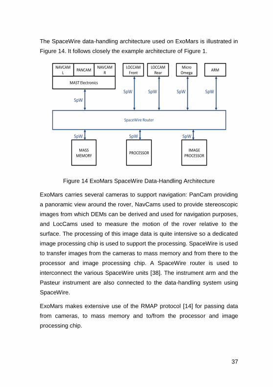
The SpaceWire data-handling architecture used on ExoMars is illustrated in
Figure 14. It follows closely the example architecture of Figure 1.
PANCAM
MAST Electronics
SpaceWire Router
PROCESSORIMAGE
PROCESSOR
SpW
SpWSpW
NAVCAML
NAVCAMR
LOCCAMFront
LOCCAMRear
MicroOmega
ARM
SpW SpW SpW
SpW
MASSMEMORY
SpW
Figure 14 ExoMars SpaceWire Data-Handling Architecture
ExoMars carries several cameras to support navigation: PanCam providing
a panoramic view around the rover, NavCams used to provide stereoscopic
images from which DEMs can be derived and used for navigation purposes,
and LocCams used to measure the motion of the rover relative to the
surface. The processing of this image data is quite intensive so a dedicated
image processing chip is used to support the processing. SpaceWire is used
to transfer images from the cameras to mass memory and from there to the
processor and image processing chip. A SpaceWire router is used to
interconnect the various SpaceWire units [38]. The instrument arm and the
Pasteur instrument are also connected to the data-handling system using
SpaceWire.
ExoMars makes extensive use of the RMAP protocol [14] for passing data
from cameras, to mass memory and to/from the processor and image
processing chip.
38
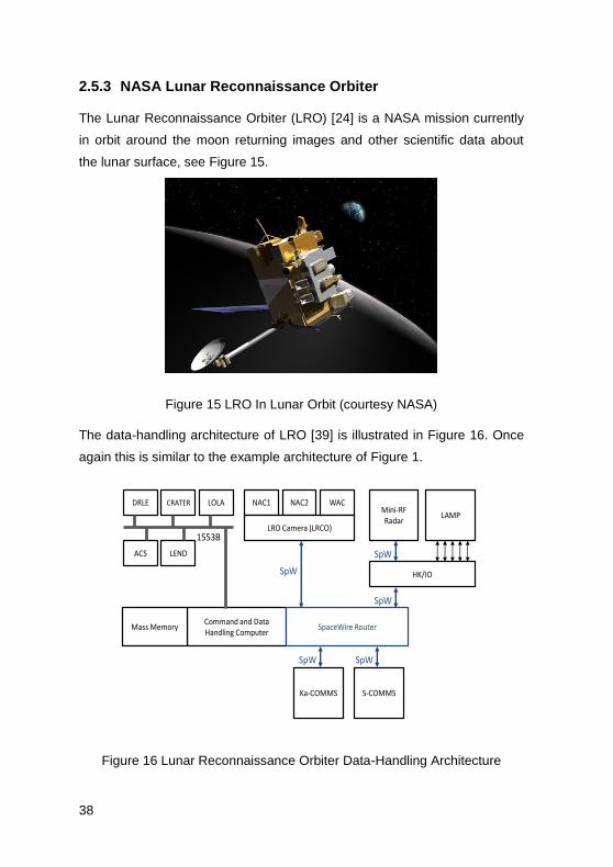
2.5.3 NASA Lunar Reconnaissance Orbiter
The Lunar Reconnaissance Orbiter (LRO) [24] is a NASA mission currently
in orbit around the moon returning images and other scientific data about
the lunar surface, see Figure 15.
Figure 15 LRO In Lunar Orbit (courtesy NASA)
The data-handling architecture of LRO [39] is illustrated in Figure 16. Once
again this is similar to the example architecture of Figure 1.
NAC1 NAC2 WAC
LRO Camera (LRCO)
Mini-RFRadar
ACS LEND
DRLE CRATER LOLA
Command and Data Handling Computer
LAMP
Ka-COMMS S-COMMS
HK/IO
1553B
SpW
SpW
SpW
SpWSpW
SpaceWire RouterMass Memory
Figure 16 Lunar Reconnaissance Orbiter Data-Handling Architecture

39
SpaceWire is used to connect the LRO Cameras (Narrow angle Cameras,
NAC1 and NAC2, and Wide Angle Camera, WAC), and Mini-RF radar
instrument, to the Command and Data-handling (C&DH) system. SpaceWire
is also used to pass data from the Command and Data-handling system to
the Ka and S-Band communications systems. Information from the Lyman-
Alpha Mapping Project (LAMP) instrument is passed into an I/O board in the
C&DH system (HK/IO) and then sent over SpaceWire to the C&DH
computer/mass memory. The C&DH computer includes a 4-port SpaceWire
router for handling the SpaceWire communications.
An example image from LRO is given in Figure 17. It shows the Apollo 12
landing site. The Apollo 12 (Intrepid) descent stage is clearly visible in the
image as is the earlier Surveyor 3 spacecraft. The black lines radiating out
from Intrepid and pointed to by arrows in other parts of this image are the
footsteps of the Apollo 12 astronauts. This image travelled over SpaceWire
twice: from the NAC to the mass memory and from the mass memory to the
downlink communication system.
Figure 17 Image from LRO Showing Apollo 12 Landing Site (courtesy
NASA)
40
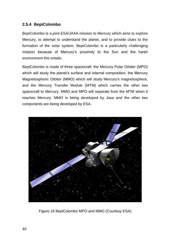
2.5.4 BepiColombo
BepiColombo is a joint ESA/JAXA mission to Mercury which aims to explore
Mercury, to attempt to understand the planet, and to provide clues to the
formation of the solar system. BepiColombo is a particularly challenging
mission because of Mercury’s proximity to the Sun and the harsh
environment this entails.
BepiColombo is made of three spacecraft: the Mercury Polar Orbiter (MPO)
which will study the planet’s surface and internal composition, the Mercury
Magnetospheric Orbiter (MMO) which will study Mercury's magnetosphere,
and the Mercury Transfer Module (MTM) which carries the other two
spacecraft to Mercury. MMO and MPO will separate from the MTM when it
reaches Mercury. MMO is being developed by Jaxa and the other two
components are being developed by ESA.
Figure 18 BepiColombo MPO and MMO (Courtesy ESA)

41
The SpaceWire data-handling architecture used on MPO is shown in Figure
19.
Mass Memory Unit
SpaceWire Router
On
-Bo
ard
Co
mp
ute
rSpW
Pa
ylo
ad
1
Pa
ylo
ad
2
Pa
ylo
ad
3
Pa
ylo
ad
4
Pa
ylo
ad
5
Pa
ylo
ad
6
Pa
ylo
ad
7
Pa
ylo
ad
8
Pa
ylo
ad
9
SpaceWire RouterSpaceWire Router
SpaceWire Router
Sp
ace
Wir
e R
ou
ter
SpW SpW
SpW
SpW
SpW
SpW
SpW SpW
X-BandTelemetry
FormatGenerator
Ka-BandTelemetry
FormatGenerator
OBC Interface
EGSE Interface
X-Band Downlink Ka-Band Downlink
Figure 19 Mercury Polar Orbiter Data-Handling Architecture
MPO uses SpaceWire for the data-handling from its nine science payloads.
These payload instruments are connected to the on-board mass memory
unit via point-to-point links and three SpaceWire routers that are integrated
within the mass memory unit. These routers are also connected to the on-
board computer and to each other in a daisy chain. This enables the on-
board computer to access each of the routers and payload instruments for
configuration and control purposes. Another router is used to connect the
mass memory unit to the X-band and Ka-band downlink telemetry format
generators, which format the payload data before sending it back to Earth.
This SpaceWire router is also attached to the on-board computer to allow
the router and downlink telemetry format generators to be configured and
controlled. SpaceWire links are also used to connect the on-board computer
to the spacecraft platform and electronic ground support equipment (EGSE).

42
The SpaceWire routing devices used are the ESA SpW-10X routers (Atmel
AT7910E).
Figure 19 has been simplified for clarity. For redundancy purposes the data-
handling units are duplicated with cross-strapping between units to enhance
overall reliability and avoid possible single-point failures.
MMO is illustrated in Figure 20 and its data-handling architecture is shown
in Figure 21.
Figure 20 BepiColombo MMO (Courtesy ESA)
43
SpacecraftSystem
Data Processing
Unit 1
Data Processing
Unit 2
MEA1
MEA2
MIA
MSA
HEP-electron
HEP-ion
ENA
MDM
MSASI
MGF-out
MGF-in
PWI
MAST/WPT-E
MEA Mercury Electron AnalyserMIA Mercury Ion AnalyserMSA Mercury Mass Spectrometer AnalyserHEP High Energy Particle InstrumentENA Energetic Neutrals AnalyserMDM Mercury Dust MonitorMSASI Mercury Sodium Atmosphere Spectral InvestigationMGF Magnetic Field InvestigationPWI Plasma Wave investigationMAST/WPA Mast and Wire Probe Antenna Control
Mission Data Processor
SpW
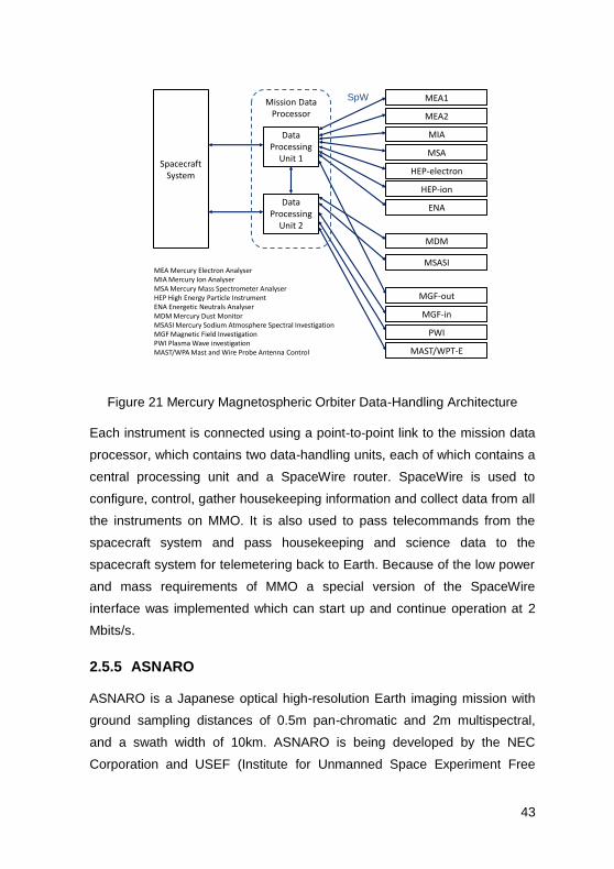
Figure 21 Mercury Magnetospheric Orbiter Data-Handling Architecture
Each instrument is connected using a point-to-point link to the mission data
processor, which contains two data-handling units, each of which contains a
central processing unit and a SpaceWire router. SpaceWire is used to
configure, control, gather housekeeping information and collect data from all
the instruments on MMO. It is also used to pass telecommands from the
spacecraft system and pass housekeeping and science data to the
spacecraft system for telemetering back to Earth. Because of the low power
and mass requirements of MMO a special version of the SpaceWire
interface was implemented which can start up and continue operation at 2
Mbits/s.
2.5.5 ASNARO
ASNARO is a Japanese optical high-resolution Earth imaging mission with
ground sampling distances of 0.5m pan-chromatic and 2m multispectral,
and a swath width of 10km. ASNARO is being developed by the NEC
Corporation and USEF (Institute for Unmanned Space Experiment Free

44
Flyer) with funding from the Japanese Ministry of Economy, Trade and
Industry. The overall objective of the ASNARO project is to develop a next-
generation high-performance mini-satellite bus system based on open
architecture techniques and manufacturing methodologies to drastically
reduce the cost and the development period with adoption of up-to-date
electronics technologies [34].
SpaceWire is used on-board ASNARO for all the data-handling. The
SpaceWire architecture is illustrated in Figure 22.
SpaceWire Router
Data-Handling Computer
Gyro
SpW
S-BandTelemetry-
Telecommand
Attitude and Orbit Control
Computer
Star Tracker
SpW
ReactionWheels
SpW
MTO
SpW
Propulsion
SpW
SpaceWire Router
SpW
Heater Control
SpW
GPSR
SpW
Power Control
SpW
Payload Control
Computer
Payload
X-BandDownlink
SpW
SpW
SpW SpW
SpW
Figure 22 ASNARO SpaceWire Networks
ASNARO uses SpaceWire for platform and attitude and orbit control
(AOCS) as well as for payload data-handling. The payload control computer
is attached to the payload using SpaceWire. The platform electronics
including the data-handling computer, payload computer, attitude and orbit
control computer, heater control, GPS receiver, power control and S-Band
telecommand-telemetry unit, are interconnected using a SpaceWire router.
A separate SpaceWire network connects the AOCS sensors and actuators
to the AOCS computer.

45
3 SpaceWire Links
In this section the operation of a SpaceWire link is considered in more
detail. SpaceWire is based on two previous standards IEEE 1355-1995 [2]
and ANSI/TIA/EIA-644 [3].
The SpaceWire standard covers the physical connectors and cables,
electrical properties, and logical protocols that comprise SpaceWire data
links and networks which are defined in the following normative protocol
levels
Physical Level – SpaceWire connectors, cables, cable assemblies
and printed circuit board tracks.
Signal Level – signal encoding, voltage levels, noise margins, and
data signalling rates used in SpaceWire.
Character Level – data and control characters used to manage
the flow of data across a SpaceWire link.
Exchange Level – protocols for link initialisation, flow control, link
error detection and link error recovery.
Packet Level – definition of how data for transmission over a
SpaceWire link is split up into packets
Network Level – structure of a SpaceWire network and the way in
which packets are transferred from a source node to a destination
node across a network. The network level also defines how link
errors and network level errors are handled.
In the following subsections each of these protocol levels will be considered
in turn up to and including the packet level.

46
3.1 Physical Level
The physical level of the SpaceWire standard covers cables, connectors,
cable assemblies and printed circuit board tracks. SpaceWire was
developed to meet the EMC specifications of typical spacecraft.
3.1.1 Cables
The SpaceWire cable comprises four twisted pair wires with a separate
shield around each twisted pair and an overall shield. To achieve a high
data signalling rate with SpaceWire over distances up to 10 m a cable with
the following characteristics is used:
Characteristic impedance of 100 ohms differential impedance,
which is matched to the line termination impedance.
Low signal-signal skew between each signal in a differential pair
and between Data and Strobe pairs.
Low signal attenuation.
Low cross-talk.
Good EMC performance.
The structure of a SpaceWire cable is illustrated in Figure 23.
Conductor 28 AWG
(7 x 36 AWG)
Insulating layer
Twisted pair(100 ohm differential impedance)
Inner shield around
twisted pair (40AWG)
Outer shield (38AWG)
Outer Jacket
Filler
Jacket
Filler
Binder
Figure 23 SpaceWire Cable Structure
47
One of the drawbacks of SpaceWire is the mass of the cable which is
around 87 g/m. A new form of SpaceWire cable is currently being developed
by ESA which is of significantly lower mass. This cable only uses one level
of shielding.
SpaceWire is able to operate at 200 Mbits/s over 10m cable. For longer
distances it is possible to increase the wire gauge of the conductors to
reduce cable attenuation.
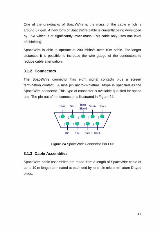
3.1.2 Connectors
The SpaceWire connector has eight signal contacts plus a screen
termination contact. A nine pin micro-miniature D-type is specified as the
SpaceWire connector. This type of connector is available qualified for space
use. The pin-out of the connector is illustrated in Figure 24.
Dout+
Dout-Sin+
Sin- Sout+
Sout-Din+
Din-
Inner
Shield
1 52 43
6 87 9
Figure 24 SpaceWire Connector Pin-Out
3.1.3 Cable Assemblies
SpaceWire cable assemblies are made from a length of SpaceWire cable of
up to 10 m length terminated at each end by nine-pin micro-miniature D-type
plugs.
48
1
2
7
6
5
4
3
8
9
Din+
Din-
Sin+
Sin-
GROUND
Sout+
Sout -
Dout+
Dout-
9
8
4
5
6
7
3
2
1
Dout+
Dout-
Sout+
Sout-
GROUND
Sin+
Sin-
Din+
Din-
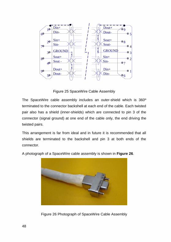
Figure 25 SpaceWire Cable Assembly
The SpaceWire cable assembly includes an outer-shield which is 360º
terminated to the connector backshell at each end of the cable. Each twisted
pair also has a shield (inner-shields) which are connected to pin 3 of the
connector (signal ground) at one end of the cable only, the end driving the
twisted pairs.
This arrangement is far from ideal and in future it is recommended that all
shields are terminated to the backshell and pin 3 at both ends of the
connector.
A photograph of a SpaceWire cable assembly is shown in Figure 26.
Figure 26 Photograph of SpaceWire Cable Assembly

49
3.1.4 Printed Circuit Board Tracks
SpaceWire can also be run over printed circuit boards (PCBs) including
backplanes. Because of the high-speed of SpaceWire signals which have a
bandwidth of over 1 GHz (at 200 Mbps the signal frequency is 100 MHz and
that of the signal edges around ten times this, giving 1 GHz) care has to be
taken with the PCB layout. The following guidelines should be adhered to:
The PCB tracks must have 100 ohm differential impedance
Track pairs well separated from other tracks
No right-angle turns
Minimal use of vias
Each signal of the differential pair to be tracked identically and kept
to the same length (< 5 mm)
Data and strobe signal pairs to be of the same length (< 5 mm)
3.2 Signal Level
The signal level part of the SpaceWire standard covers signal voltage levels,
noise margins and signal encoding.
3.2.1 Signal Level and Noise Margins
Low Voltage Differential Signalling (LVDS) as defined in ANSI/TIA/EIA-644
[9] is specified as the signalling technique for SpaceWire. LVDS uses
balanced signals to provide very high-speed interconnection using a low
voltage swing (350 mV typical). The balanced or differential signalling
provides adequate noise margin to enable the use of low voltages in
practical systems. The low voltage swing results in relatively low power
consumption at high speed. LVDS is appropriate for connections between
chips on a board, boards in a unit, and unit to unit interconnections over
distances of 10 m or more. The LVDS signalling levels are illustrated in
Figure 27.

50
0 1 0
Vin-
Vin+
1.2V typical
(O V differential)
+250 to +400 mV
typical
-250 to -400 mV
typical
Voltage Across 100 ohm Termination Resistor
+100 mV typical
-100 mV typical
Transition
Region
Receiver Input Thresholds
O V (differential)
[Vin+ - Vin-]
Figure 27 LVDS Signalling Levels
A typical LVDS driver and receiver are shown in Figure 28, connected by a
media (cable or PCB traces) of 100 ohm differential impedance. The LVDS
driver uses current mode logic. A constant current source of around 3.5 mA
provides the current that flows out of the driver, along the transmission
medium, through the 100 ohm termination resistance and back to the driver
via the transmission medium. Two pairs of transistor switches in the driver
control the direction of the current flow through the termination resistor.
When the driver transistors marked “+” in Figure 28 are turned on and those
marked “-” are turned off, current flows as indicated by the arrows on the
diagram creating a positive voltage across the termination resistor. When
the two driver transistors, marked “-”, are turned on and those marked “+”
are turned off, current flows in the opposite direction producing a negative
voltage across the termination resistor. LVDS receivers are specified to
have high input impedance so that most of the current flows through the
termination resistor to generate around 350 mV with the nominal 3.5 mA
current source.
-
+
+
-
Vcc
~3.5mA
DRIVER
RECEIVER
100R
+
-
100R Transmission Medium
Figure 28 LVDS Operation

51
LVDS has several features that make it very attractive for data signalling [6]:
Near constant total drive current (+3.5 mA for logic 1 and -3.5 mA
for logic 0) which decreases switching noise on power supplies.
High immunity to ground potential difference between driver and
receiver, LVDS can tolerate at least ±1 V ground difference.
High immunity to induced noise because of differential signalling,
normally using twisted-pair cable.
Low EM emission because small equal and opposite currents
create small electromagnetic fields which tend to cancel one
another out.
Not dependent upon particular device supply voltage(s).
Simple 100 ohm termination at receiver.
Failsafe operation - the receiver output goes to the high state
(inactive) whenever
o the receiver is powered and the driver is not powered,
o the inputs short together,
o input wires are disconnected.
Power consumption is typically 50 mW per driver/receiver pair for
LVDS compared to 120 mW for ECL/PECL.
The signal levels and noise margins for SpaceWire are derived from
ANSI/TIA/EIA-644 [3] which defines the driver output characteristics and the
receiver input characteristics. The eye diagram for SpaceWire signals sent
over 10 m of cable at 200 Mbits/s baud rate is shown in Figure 29.

52
Figure 29 SpaceWire Eye Diagram (200 MHz, 10 m cable)
3.2.2 Data encoding
SpaceWire uses Data-Strobe (DS) encoding. This is a coding scheme
which encodes the transmission clock with the data into Data and Strobe so
that the clock can be recovered by simply XORing the Data and Strobe lines
together. The data values are transmitted directly and the strobe signal
changes state whenever the data remains constant from one data bit
interval to the next. This coding scheme is illustrated in Figure 30. The DS
encoding scheme is also used in the IEEE 1355-1995 [7] and IEEE 1394-
1995 (Firewire) standard [41].
The reason for using DS encoding is to improve the skew tolerance to
almost 1-bit time, compared to 0.5 bit time for simple data and clock
encoding.
0 0 1 1 0 1 1 00 1Data
DS
CLK
Figure 30 Data-Strobe (DS) Encoding
53
A SpaceWire link comprises two pairs of differential signals, one pair
transmitting the D and S signals in one direction and the other pair
transmitting D and S in the opposite direction. That is a total of eight wires
for each bi-directional link.
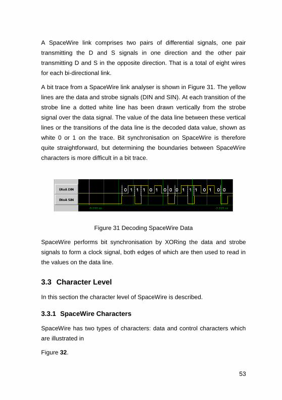
A bit trace from a SpaceWire link analyser is shown in Figure 31. The yellow
lines are the data and strobe signals (DIN and SIN). At each transition of the
strobe line a dotted white line has been drawn vertically from the strobe
signal over the data signal. The value of the data line between these vertical
lines or the transitions of the data line is the decoded data value, shown as
white 0 or 1 on the trace. Bit synchronisation on SpaceWire is therefore
quite straightforward, but determining the boundaries between SpaceWire
characters is more difficult in a bit trace.
Figure 31 Decoding SpaceWire Data
SpaceWire performs bit synchronisation by XORing the data and strobe
signals to form a clock signal, both edges of which are then used to read in
the values on the data line.
3.3 Character Level
In this section the character level of SpaceWire is described.
3.3.1 SpaceWire Characters
SpaceWire has two types of characters: data and control characters which
are illustrated in
Figure 32.

54
Data characters which hold an eight-bit data value transmitted
least-significant bit first. Each data character contains a parity-bit, a
data-control flag and the eight-bits of data. The parity-bit covers
the previous eight-bits of data or two-bits of control code, the
current parity-bit and the current data-control flag. It is set to
produce odd parity so that the total number of 1’s in the field
covered is an odd number. The data-control flag is set to zero to
indicate that the current character is a data character.
Control characters which hold a two-bit control code. Each control
character is formed from a parity-bit, a data-control flag and the
two-bit control code. The data-control flag is set to one to indicate
that the current character is a control character. Parity coverage is
similar to that for a data character. One of the four possible control
characters is the escape code (ESC). This can be used to form
longer control codes. Two longer control codes are specified and
valid which are the NULL code and the Time-Code.
In addition to the data and control characters there are two control codes:
NULL and time-codes.
NULL is formed from ESC followed by the flow control token (FCT).
NULL is transmitted, whenever a link is not sending data or control
tokens, to keep the link active and to support link disconnect
detection.
The Time-Code is used to support the distribution of system time
across a network. A Time-Code is formed by ESC followed by a
single data-character.

55
P 0
0
X
1
X
2
X
3
X
4
X
5
X
6
X
7
X
Data Characters
Parity Bit
Data-Control Flag
LSB MSB
Control Characters
P 1 0 0FCT Flow Control Token
P 1 0 1EOP Normal End of Packet
P 1 1 0EEP Error End of Packet
P 1 1 1ESC Escape
P 1 1 1 NULL0 1 0 0
Control Codes
P 1 1 1
0 1 2 3 4 5 6 7
LSB MSB
0 T T T T T T T T1 Time-code
Figure 32 Data and Control Characters and Control Codes
3.3.2 Parity Coverage
The parity coverage for SpaceWire is a bit unusual, as it follows that of
IEEE1355-1995. Because of the different lengths of control and data
character, the parity field of the previous character includes the data/control
flag of the next character. This is so that the length of the following character
is validated by the parity bit before that character is decoded. This avoids
incorrect decoding of a character when its data/control flag is in error.
P 0 X X XXXX XX P 01 1 P 01 0
Data Character EOP FCT
Parity
Coverage
Parity
Coverage
Figure 33 Data and Control Characters Parity Coverage

56
3.3.3 Character Priority
Character transmission is prioritised as follows:
Time-codes - highest priority
FCTs
N-Chars
NULLs - lowest priority
Time-codes are highest priority because they are used to transfer time or
synchronisation information and have to be delivered with low jitter. FCTs
are higher priority than N-Chars, so that a large amount of data being sent in
one direction does not stop FCTs being sent, thus causing the other end of
the link to stop sending data because it has run out of flow control. NULLs
are the lowest priority as they are only sent to keep the link running and
synchronised when there is nothing else to send.
3.3.4 Character Functions
Characters in SpaceWire are used for three different functions: link control,
sending packets and sending time-codes.
The characters and control codes used for link control are the NULL and
FCT, which are known as L-Chars or Link characters. They are used in the
Exchange level and not passed up to any higher level.
The characters and control codes used for sending packets are the data
characters and end of packet markers (EOP and EEP), which are known as
N-Chars or Normal characters. These characters are passed up to the
packet layer.
The time-codes are used for sending time and synchronization information
and are passed to the time-code handler of a node or router.
A SpaceWire link interface interleaves L-Chars, N-Chars and time-codes. N-
Chars from one packet are not interleaved with N-Chars from another

57
packet. A received character should have its parity checked before it is
acted upon.
3.3.5 Character Synchronisation
Character synchronisation is performed only once when a link is started or
re-started following a link disconnection. This is illustrated in Figure 34.
Figure 34 SpaceWire Link Start-up and Character Synchronisation
One end of the link (bottom trace, End B) starts to send Nulls, a specific
sequence of 8 data bits. The other end detects this sequence, synchronises
its receiver and starts to send Nulls back (top trace, End A). When End B
receives these Nulls it synchronises its receiver. Further handshaking is
done between the two ends of the link which is described later in section
3.4. The SpaceWire interfaces initially start operating at a line data
signalling rate of 10 Mbits/s. Once the connection has been made the two
ends of the link can switch to higher speed operation if required. This is
clearly visible in Figure 34.
Before a link sends its first Null both data and strobe lines are set low as
shown in Figure 35.

58
0 1 1 1 0 1 0 0
First NULL
D
S
Figure 35 SpaceWire Link Start-Up Bit Sequence
Unfortunately the bit sequence for a Null is not unique in a SpaceWire bit
sequence so it cannot be reliably used for resynchronisation of the signals
without first stopping the SpaceWire link and then restarting and re-
synchronising it.
3.4 Exchange Level
The SpaceWire exchange level is responsible for exchanging information
between the two ends of a link. It provides the following functions: link
initialisation, flow-control and error-handling.
3.4.1 SpaceWire Link Interface
At each end of a SpaceWire link is a SpaceWire link interface. A block
diagram of a link interface is illustrated in Figure 36.

59
FlowControl
TX FIFO
RX FIFO
StateMachine
TX RX
SpWPacket
TX
SpWPacket
RXTime-Code
RXTime-Code
TXPacket Level
Exchange Level
Character Level
Signal Level
Physical Lvel
SpaceWire CODEC Interface
Figure 36 SpaceWire Link Interface Block Diagram
The SpaceWire link can send and receive SpaceWire packets and time-
codes once it has been initialised and is running. As described in section
2.3.2 a SpaceWire packet comprises a destination address, cargo and end
of packet marker. To send a SpaceWire packet over a SpaceWire link it is
passed character by character to the transmit FIFO starting with the first
character of the destination address. SpaceWire packets are received into
the RX FIFO and can be read out by the application. To send a time-code, it
is presented to the SpaceWire interface and will be transmitted as soon as
the current character has finished being transmitted. When time-codes are
received they are made available via the time-code interface. Time-codes
need to be validated before they are used, see section 5.
Before a SpaceWire link can send and receive SpaceWire packets and
time-codes, it needs to be initialised. This is done under control of the link

60
state machine. This state machine also manages recovery from any errors
detected on the link, by re-initialising the link.
To prevent overflow of the receive FIFO the SpaceWire interface includes
circuitry to monitor the amount of space available in the receive FIFO and to
regulate the data being sent from the other end using flow-control tokens.
3.4.2 Link Initialisation
Link initialisation is necessary to get both ends of the link fully synchronised
and ready to receive data and EOP characters and time-codes. Bit
synchronisation is performed by decoding the data-strobe signals to
produce the bit clock and data stream. Character synchronisation is
performed once during link initialisation. Both ends of the link have to be
character synchronised or the link will automatically reset and attempt to
resynchronise.
Following reset the SpaceWire interface is held in the reset state until it is
instructed to start and attempt to make a connection with the SpaceWire
interface at the other end of the link. A connection is made following a
handshake that ensures both ends of the link are able to send and receive
characters successfully. Each end of the link sends NULLs, waits to receive
a NULL, then sends FCTs and waits to receive an FCT. Since a SpaceWire
interface is not allowed to send FCTs until it has received a NULL, receipt of
one or more NULLs followed by receipt of an FCT means that the other end
of the link has received NULLs successfully and that full connection has
been achieved. This exchange of Nulls and FCTs is known as the Null/FCT
handshake.
Link initialisation is handled by a state machine in each of the SpaceWire
interfaces at either end of the SpaceWire link. The basic state machine is
illustrated in Figure 37. This diagram is simplified to highlight the link
initialisation procedure.

61
Ready
Reset Tx
Enable Rx
Started
Send Nulls
Enable Rx
ErrorReset
Reset Tx
Reset Rx
ErrorWait
Reset Tx
Enable Rx
Reset
After 6.4usLink Disabled
Run
Send FCTs/NChars/Nulls
Enable Rx
After
12.8us
Start Link
gotFCT
Connecting
Send FCTs/Nulls
Enable Rx
gotNull
Figure 37 SpaceWire Interface State Machine
On reset the SpaceWire interface state machine enters the ErrorReset state
where both the transmitter and receiver in the SpaceWire interface are
reset. The state machine remains in this state for 6.4 µs to ensure that the
interface is properly reset, and then moves to the ErrorWait state where it
keeps the transmitter reset but enables the receiver. The reason for this will
become clear later. After waiting 12.8 µs in the ErrorWait state the
SpaceWire interface moves to the Ready state, where it waits for a
command to start the link. When the SpaceWire interface is instructed to
start the link (by the local application logic using the SpaceWire interface) it
moves to the Started state where it begins to send out Nulls. If the other end
(End B) of the link is also sending Nulls then End A will receive the Null
(gotNull) and move to the Connecting state. In the Connecting state the
transmitter is allowed to send Nulls and FCTs. It will send out an initial burst
of FCTs (see flow control section later on) as part of the initialisation
handshake. The other end of the link (End B) will have received Nulls and
with therefore also be in the Connecting state sending out FCTs and Nulls.
The FCTs will be received at End A and the state machine will move to the

62
Run state. In the Run state both ends of the link have made a connection (or
are just about to) and the SpaceWire interface is ready to start transferring
data. The link will now remain in the Run state until one of the SpaceWire
interfaces is disabled by the local application logic asserting the Link
Disabled control bit.
If the other end of the link (End B) is not ready and does not send Nulls and
FCTs when expected, End A will wait in the Started or Connecting state for
12.8 µs and then give up waiting, move back to the ErrorReset state and try
again to make a connection. This is illustrated in Figure 38.
Ready
Reset Tx
Enable Rx
Started
Send Nulls
Enable Rx
ErrorReset
Reset Tx
Reset Rx
ErrorWait
Reset Tx
Enable Rx
Reset
After 6.4usLink Disabled
Run
Send FCTs/NChars/Nulls
Enable Rx
After
12.8us
Start Link
gotFCT
Connecting
Send FCTs/Nulls
Enable Rx
gotNull
After
12.8 us
After
12.8 us
Figure 38 SpaceWire Interface State Machine moves to ErrorReset when
no Nulls or FCTs received
To avoid having to set both the Start Link bit in both ends of the link to start
a link, an Auto-Start mode is included in the SpaceWire state-machine. A
SpaceWire interface in the Auto-Start mode will automatically start up when
it receives a bit (gotBit) on its receiver. This functionality is achieved by

63
adding an extra condition on the transition between the Ready and Started
states. This addition is illustrated in Figure 39.
Ready
Reset Tx
Enable Rx
Started
Send Nulls
Enable Rx
ErrorReset
Reset Tx
Reset Rx
ErrorWait
Reset Tx
Enable Rx
Reset
After 6.4usLink Disabled
Run
Send FCTs/NChars/Nulls
Enable Rx
After
12.8us
Start Link OR (AutoStart AND GotBit)
gotFCT
Connecting
Send FCTs/Nulls
Enable Rx
gotNull
After
12.8 us
After
12.8 us
Figure 39 SpaceWire Interface State Machine with Auto-Start
One end of the link (End B) has its AutoStart control bit set and has reset,
moved through ErrorReset and ErrorWait, and is now sitting in the Ready
state. The other end of the link (End A) has also reset and is waiting in the
Ready state. When End A gets the command to Start Link, it moves to the
Started state and begins sending Nulls. End B receives the start of the Null
and gotBit is asserted causing it to also move to the Started state. The
Null/FCT handshake now takes place with both ends moving through
Started and Connecting to Run.
When one end of the link is trying to make a connection, i.e. Start Link is
asserted, and the other end of the link (End B) is not ready to make a
connection for whatever reason, End A will send Nulls for 12.8 µs and then
go silent for 19.2 µs (6.4 µs + 12.8 µs) repeatedly. Observing bursts of Nulls

64
from one end of a link while nothing is being sent in the other direction is a
clear indication that one end is trying to send and the other end is not
responding. This could be because that end of the link does not have its
Auto-Start control bit asserted, or alternatively its Disable bit is asserted.
The link initialisation sequence is shown in Figure 40. The sequence of
characters under A->B Event is for one direction of the link (characters
being sent from End A to End B) while that under B->A Event is the other
direction.
1. The link is disconnected causing both ends of the link to reset, moving
through the ErrorReset and ErrorWait states to the Ready state.
2. End B of the link has Start Link asserted and so moves to the Started
state and begins sending Nulls, which are received at End A initially
causing GOT-BIT to be asserted and then a series of Nulls to be
received.
3. End A has AutoStart asserted, so as soon as it has received the first bit
(GOT-BIT) it moves to the Started state and sends at least one Null,
which is received at End B.
4. When End A receives a Null, and after it has sent at least one Null in
response, it moves to the Connecting state and is able to send one or
more FCTs.
5. The Null from End A is received at End B, so End B moves to the
Connecting state, and is able to send one or more FCTs.
6. The FCT from End A is received at End B, so End B moves to the Run
state and switches to the required link operating speed (note the
change in character timing).
7. The FCT sent from End B is received at End A, so End A moves to the
Run state and switches to the required link operating speed. The link is
now running in both directions.
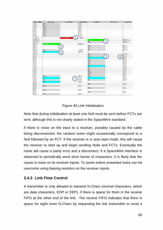
65
12
3
45 6
7
Figure 40 Link Initialisation
Note that during initialisation at least one Null must be sent before FCTs are
sent, although this is not clearly stated in the SpaceWire standard.
If there is noise on the input to a receiver, possibly caused by the cable
being disconnected, the random noise might occasionally correspond to a
Null followed by an FCT. If the receiver is in auto-start mode, this will cause
the receiver to start up and begin sending Nulls and FCTs. Eventually the
noise will cause a parity error and a disconnect. If a SpaceWire interface is
observed to periodically send short bursts of characters, it is likely that the
cause is noise on its receiver inputs. To some extent unwanted noise can be
overcome using biasing resistors on the receiver inputs.
3.4.3 Link Flow Control
A transmitter is only allowed to transmit N-Chars (normal characters, which
are data characters, EOP or EEP), if there is space for them in the receive
FIFO at the other end of the link. The receive FIFO indicates that there is
space for eight more N-Chars by requesting the link transmitter to send a

66
flow control token (FCT). The FCT is received at the other end of the link
(end B) enabling the transmitter at end B to send up to eight more N-Chars.
If there is more room in the receive FIFO, multiple FCTs can be sent, one
for every eight spaces in the receive buffer. Correspondingly, if multiple
FCTs are received then it means that there is a corresponding amount of
space available in the receive FIFO e.g. four FCTs means that there is room
for 32 N-Chars. Each FCT is exchanged in this way for 8 N-Chars. The
operation of flow control is illustrated in Figure 41.
1
2
Figure 41 Flow Control With FCTs
The FCT sent by End B and received by End A (1), permits End A to send
eight more N-Chars (2). The FCT goes in the opposite direction to the data
that it is exchanged for. The SpaceWire link in Figure 41, is sending data in
both directions of the link so FCTs are also being sent in both directions.
A SpaceWire interface is permitted to have a maximum of seven
outstanding FCTs, corresponding to 56 N-Chars. Buffers larger than this can
be used if required, but seven FCTs are more than enough to support

67
continuous data transfer across a link. Smaller FIFOs may also be used, in
which case fewer than the maximum of seven FCTs will ever be
outstanding.
3.4.4 Link Error Handling
There are several types of error that can occur in a SpaceWire link:
Disconnect error – the link is disconnected in one or both
directions, so data or Nulls are not received.
Parity error – a received character contains a parity error.
Escape error – an Escape character is received which is followed
by another Escape, an EOP, or EEP, which are character
sequences that are not allowed.
Credit error – an N-Char arrives when there is no room for it in the
receive FIFO.
Link disconnection is detected when following reception of a data bit no new
data bit is received within a link disconnect timeout window (850 ns). Once a
disconnection error has been detected, the link attempts to recover from the
error.
Parity errors occurring within a data or control character are detected when
the next character is sent, since the parity bit for a data or control character
is contained in the next character. Once a parity error has been detected,
the link attempts to recover from the error.
Following an error or reset the link attempts to re-synchronise and restart
using an “exchange of silence” protocol (see Figure 42). The end of the link
that is either reset or that finds an error, ceases transmission. This is
detected at the other end of the link as a link disconnect and that end stops
transmitting too. The first link resets its input and output for 6.4 s to ensure
that the other end detects the disconnect. The other end also waits for 6.4
s after ceasing transmission. Each link then waits a further 12.8 s before
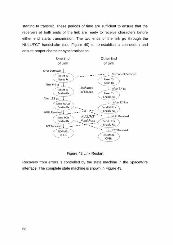
68
starting to transmit. These periods of time are sufficient to ensure that the
receivers at both ends of the link are ready to receive characters before
either end starts transmission. The two ends of the link go through the
NULL/FCT handshake (see Figure 40) to re-establish a connection and
ensure proper character synchronisation.
Reset TxReset Rx
Reset TxEnable Rx
Send NULLsEnable Rx
Send FCTsEnable Rx
NORMALOPER.
Error Detected
After 6.4 µs
After 12.8 µs
NULL Received
Reset TxReset Rx
Reset TxEnable Rx
Send NULLsEnable Rx
Send FCTsEnable Rx
NORMALOPER.
Disconnect Detected
After 6.4 µs
After 12.8 µs
NULL Received
One Endof Link
Other Endof Link
FCT Received
FCT Received
Exchangeof Silence
NULL/FCTHandshake
Figure 42 Link Restart
Recovery from errors is controlled by the state machine in the SpaceWire
interface. The complete state machine is shown in Figure 43.

69
Reset
ReadyReset Tx
Enable Rx
StartedSend NULLsEnable Rx
ErrorResetReset TxReset Rx
ErrorWaitReset Tx
Enable Rx
[Link Enabled]
After 6.4 µs
After12.8 µs
gotNULL
RxErr ORCreditError OR[Link Disabled]
RunSend Time-Codes/
FCTs/N-Chars/NULLsEnable Rx
RxErr ORgotFCT OR
gotN-Char ORgotTime-Code
gotFCT
ConnectingSend FCTs/NULLs
Enable Rx
RxErr OR gotFCT OR
gotN-Char ORgotTime-CodeRxErr OR
gotFCT ORgotN-Char ORgotTime-Code ORafter 12.8 µs
RxErr ORgotN-Char OR
gotTime-Code ORafter 12.8 µs
Figure 43 SpaceWire Interface State Machine Error Recovery
The error conditions that can occur are shown in red. Any error that is
detected results in a transition to the ErrorReset which starts the error
recovery cycle.
RxErr is a Disconnect Error, Parity Error, or Escape Error.
Disconnect Error detection is enabled following link reset, only after the first
bit has been received.
An RxErr can be detected in any state, except ErrorReset, and will result in
a transition to ErrorReset.
In the ErrorWait, Ready and Started states it should not be possible to
receive an FCT, N-Char or time-code, because the link has not yet been
fully initialised. If any of these characters are received it is an error and
results in a transition to the ErrorReset state.

70
In the Connecting state it should not be possible to receive N-Chars or time-
codes as the link is only partially connected, an FCT must be received
before any of these other characters, finishing link initialisation and causing
a transition to the Run state. If any N-Chars or time-codes are received in
the Connecting state, it is an error and the state machine moves to the
ErrorReset state.
Detection of Parity Error, Escape Error, gotFCT, gotN-Char, and gotTime-
Code are only enabled after the first Null has been received, i.e. gotNULL
asserted.
Thus
RxErr OR gotFCT OR gotN-Char OR gotTime-Code
is really
RxErr OR (gotNULL AND (gotFCT OR gotN-Char OR gotTime-Code)).
3.4.5 Auto-Start
The Auto-Start facility in a SpaceWire link interface is provided to permit the
far end of the link to initiate starting of the link. One end of the link is set to
Auto-Start. Sometime later the other end of the link is started and begins
sending Nulls. These are received by the end of the link set to Auto-Start,
which responds to the reception of Nulls by starting and sending Nulls.
Initialisation of the link takes place and data can then be sent over the link.
Both ends of a SpaceWire link can be set to Auto-Start, in which case either
end can be started and cause link initialisation.
Without the Auto-Start facility both ends of the link would have to be started
specifically. One end could be started, sending Nulls for a long time before
the other end is also started. This wastes power.
The condition for enabling a link to begin initialisation is:

71
[Link Enabled] = ( NOT [Link Disabled] ) AND ([LinkStart] OR (
[AutoStart] AND gotNULL ))
Where:
LinkDisabled is a flag set by software or hardware to indicate that
the link is disabled,
LinkStart is a flag set by software or hardware to start a link,
AutoStart is a flag set by software or hardware to request the link to
start automatically on receipt of a NULL,
gotNULL is a flag indicating that the link interface has received a
NULL.
If the link is disabled, LinkDisabled asserted, the other flags are ignored and
the link will not attempt to start initialisation, until LinkDisabled is de-
asserted.
3.5 Packet Level
The packet level of SpaceWire simply defines the fields in a SpaceWire
packet: destination address, cargo and end of packet marker, as illustrated
in Figure 44.
Destination Address Cargo EOP
Figure 44 SpaceWire Packet Format
The "Destination Address" is the first part of the packet to be sent and is a
list of data characters that represents either the identity of the destination
node or the path that the packet has to take through a SpaceWire network
to reach to the destination node. In the case of a point-to-point link directly
between two nodes (no routers in between) the destination address is not
necessary.

72
The "Cargo" is the data to be transferred from source to destination. Any
number of data bytes can be transferred in the cargo of a SpaceWire
packet.
The "End of Packet" (EOP) is used to indicate the end of a packet. The data
character following an End of Packet is the start of the next packet. There is
no limit on the size of a SpaceWire packet.
In addition to the normal end of packet marker (EOP), there is another end
of packet marker, the Error End of Packet marker (EEP), which indicates
that the packet has been terminated prematurely because of an error that
occurred as the packet traversed a SpaceWire link or network. A packet
terminated by an EEP is illustrated in Figure 45.
Destination Address Cargo - incomplete EEP
Figure 45 SpaceWire Packet Terminated by EEP
When a packet is terminated by an EEP it is likely that the Cargo is
incomplete and may contain some erroneous data characters. It is
also possible for an error to occur at the start of the packet, while
sending the destination address. In this case, there is no cargo, just
an incomplete destination address followed by an EEP. If this
incomplete destination address is a path address, as the packet
terminated by the EEP moves across the SpaceWire network, each
router will forward the packet and delete the leading character of the
packet. Eventually all the destination address characters will be
deleted before the packet arrives at its destination, since it was an
incomplete destination address. All that is left is an EEP. Since a
router cannot know where to forward an EEP on its own it will simply
delete the EEP. The prematurely terminated packet will then have
disappeared completely.
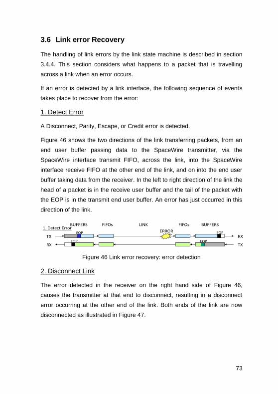
73
3.6 Link error Recovery
The handling of link errors by the link state machine is described in section
3.4.4. This section considers what happens to a packet that is travelling
across a link when an error occurs.
If an error is detected by a link interface, the following sequence of events
takes place to recover from the error:
1. Detect Error
A Disconnect, Parity, Escape, or Credit error is detected.
Figure 46 shows the two directions of the link transferring packets, from an
end user buffer passing data to the SpaceWire transmitter, via the
SpaceWire interface transmit FIFO, across the link, into the SpaceWire
interface receive FIFO at the other end of the link, and on into the end user
buffer taking data from the receiver. In the left to right direction of the link the
head of a packet is in the receive user buffer and the tail of the packet with
the EOP is in the transmit end user buffer. An error has just occurred in this
direction of the link.
FIFOsBUFFERS FIFOs BUFFERSLINK
EOP
EOPTX
RX TX
RX
1. Detect ErrorERROR EOP
EOP
Figure 46 Link error recovery: error detection
2. Disconnect Link
The error detected in the receiver on the right hand side of Figure 46,
causes the transmitter at that end to disconnect, resulting in a disconnect
error occurring at the other end of the link. Both ends of the link are now
disconnected as illustrated in Figure 47.

74
FIFOsBUFFERS FIFOs BUFFERSLINK
EOP
EOPTX
RX TX
RX
2. DisconnectEOP
EOP
Figure 47 Link error recovery: link disconnection
3. Terminate Packets with EEPs
The information in the receive FIFOs has an EEP appended to it, as soon as
there is room in each FIFO to add one. This terminates the received part of
the packet, so that it can continue on its way through the SpaceWire
network. This is illustrated in Figure 48.
FIFOsBUFFERS FIFOs BUFFERSLINK
EOPTX
RX TX
RX
3. Add EEP to RX FIFO
EEP
EEPEOP EOP
EOP
Figure 48 Link error recovery: terminate packets with EEPs
4. Spill Rest of Packet
The remainder of the packet which has not yet been transferred across the
link has to be discarded, since one or more N-Chars will have been lost or
corrupted due to the error on the link. The tail end of the packet that has not
yet been sent across the link contains valid data, but its destination is not
clear: for example, it could have been an EOP that was lost when the error
occurred on the link. Since the destination is unknown all that can be done
with the tail end of the packet is to discard it. Data is read by the transmitter
and spilt until the EOP (or EEP) is reached. The character following the
EOP will be the destination address at the start of the next packet. The
result after spilling the packet is shown in Figure 49.

75
FIFOsBUFFERS FIFOs BUFFERSLINK
EOP
EOPTX
RX TX
RX
4. Delete Data in TX until next EOPEOP EEP
EEP
Figure 49 Link error recovery: spill rest of packet
5. Reconnect
Now the SpaceWire link has tidied up after the error, the link can be re-
initialised and the connection re-established. This is shown in Figure 50.
FIFOsBUFFERS FIFOs BUFFERSLINK
EOPTX
RX TX
RX
5. ReconnectEEP
EEP
Figure 50 Link error recovery: reconnect
6. Continue Packet Transfer
With the link restarted the next packet, whose head and destination address
is waiting in the transmit FIFO, can be sent. Normal operation has resumed.
This is shown in Figure 51.
FIFOsBUFFERS FIFOs BUFFERSLINK
EOP
EOPTX
RX TX
RX
6. Continue OperationEEP
EEP
Figure 51 Link error recovery: continue operation
The error recovery mechanism works across networks comprised of a
number of routing switches. Only the link on which the error occurs is reset
(disconnect/reconnect). All the other links continue operation. Normally only
the packet in which the error occurred is partly lost and all other packets
remain valid. In some cases more than one packet can be lost due to the
time taken for link disconnection.

76
If the header byte (i.e. first byte after an EOP or EEP) is corrupted, the
entire packet is lost and the data is not propagated across a network. The
routing switch simply disposes of the packet.
If the error occurs in a EOP (or EEP), two packets are affected: the one
before the EOP where all the data is sent but no EOP is received, and the
following one because the link transmitter “spills” the packet until the next
EOP (or EEP).
If the error occurs in a NULL or FCT inserted in the data stream for a
packet, the packet being sent is discarded from that point on. This is
because it is not known what the character was before it was corrupted.
The time taken for complete recovery from the error on the link will depend
upon how long it takes to spill the tail end of the packet being transferred
when the link error occurred, which depends on the size of that packet. The
tail may have to be pulled out from the packet source, through one or more
routers making up a SpaceWire network as it is being split.
The decision about what to do with the packet that terminates with the EEP
is up to the user application.

77
4 SpaceWire Networks
SpaceWire networks are built from SpaceWire links, nodes and routers. The
links and routers are there to connect together nodes so that they can
exchange information and work together to perform some required function.
4.1 SpaceWire Nodes
A node is a piece of equipment that is using the services of a SpaceWire
link or network. It is a source or destination of SpaceWire packets, an end-
point on a SpaceWire network. For example, an instrument, mass-memory
unit or processor attached to a SpaceWire network is a SpaceWire node.
A node can have more than one SpaceWire interface and may have more
than one logical address.
4.2 SpaceWire Routing Switch
A SpaceWire router connects together many nodes and provides a means
of routing packets from one node to one of many other possible nodes. A
SpaceWire router comprises a number of SpaceWire link interfaces and a
switch matrix. The switch matrix enables packets arriving at one link
interface to be transferred to and sent out of another link interface on the
router. Each link interface may be considered as comprising an input port
(the link interface receiver) and an output port (the link interface transmitter)
as illustrated in Figure 52.

78
SWITCHMATRIX
INPUTPORT 1
INPUTPORT 2
INPUTPORT 3
INPUTPORT 4
INPUTPORT 5
INPUTPORT 6
OUTPUTPORT 1
OUTPUTPORT 2
OUTPUTPORT 3
OUTPUTPORT 4
OUTPUTPORT 5
OUTPUTPORT 6
LINK INTERFACE 1
LINK INTERFACE 6
Figure 52 Router Switch Matrix
A SpaceWire router transfers packets from the input port of the switch
where the packet arrives, to a particular output port determined by the
packet destination address. A router uses the leading data character of a
packet (one of the destination identifier characters) to determine the output
port of the router to which the packet is to be routed. If there are two input
ports waiting to use a particular output port when the previous packet has
finished being sent then an arbitration mechanism in the output port decides
which input port is to be served.
4.3 Routing Tables
A routing table within the router is used to translate from the destination
address at the front of a packet to the port number through which the packet
will be sent. The router addresses are assigned as shown in Table 1.

79
The internal configuration port is used to access configuration and status
information of the router. A SpaceWire packet arriving at any port of the
router with a leading destination address value of 0 will be routed to the
configuration port. Configuration information that can be accessed via the
configuration port includes the routing table, enabling the routing information
to be programmed over the SpaceWire network. All SpaceWire routers have
a configuration port. Since the configuration port is both the source and
destination of SpaceWire packets, that makes the configuration and status
circuitry of a router a node.
The physical output ports are the actual SpaceWire ports on the router. For
connecting to equipment local to the router it is not always necessary to use
a SpaceWire link. In this case, a FIFO port can be used instead. The FIFO
port is bi-directional and behaves like a SpaceWire port as far as the router,
but there is no SpaceWire link attached to it. Instead, some user application
connects directly to the FIFO port. The physical output ports of a router
include both the SpaceWire ports and the FIFO ports. The physical output
ports are always numbered from one upwards and normally the SpaceWire
ports are first. So a router with four SpaceWire ports and two FIFO ports
would number the SpaceWire ports 1 to 4 and the FIFO ports 5 and 6. FIFO
ports are also called external or parallel ports, meaning external to the
Table 1 Router Addresses
Address Range Function
0 Internal Configuration Port
1-31 (01-1F hex) Physical Output Ports
32-254 (20-FE hex) Logical Addresses, which are mapped
on to the physical output ports
255 (FF hex) Reserved

80
SpaceWire network, and parallel as opposed to the serial SpaceWire link. A
router is allowed to have a maximum of 31 physical ports, hence the
physical output ports are numbered 1 to 31 maximum.
Logical addresses are mapped by the routing table to physical output ports.
It is necessary to be able to distinguish between path and logical addresses
so that the router can handle them appropriately. This is done in a simple
way: the value of the leading address character of a packet determines
whether it is a path or logical address, if it is in the range 0 to 31 it is a path
address, if it is in the range 32 to 255 it is a logical address. A path address
is used directly to determine the output port that the packet is to be
forwarded through. A logical address is used as an index into the routing
table from which the physical port number is determined. The packet is then
forwarded through the specific output port.
Logical address 255 is reserved for future applications and should not be
used.
An example routing table for a router with four SpaceWire ports and the
configuration port is illustrated in Figure 53. A ‘1’ in the table maps an
address to an output port number. The configuration port (port 0) is
accessed only via path addressing with the address 0. Ports 1 to 4 are
accessed using path addresses 1 to 4 respectively. Path addresses beyond
address 4 have no meaning in a 4-port router and give rise to a routing
error. Logical addresses can be used to access any of the four output ports
depending on how the routing table is programmed. For example in Figure
53, logical address 33 has been programmed to port 4. Any packets arriving
with address 33 will be routed to output port 4.

81
Address Port 0 Port 1 Port 2 Port 3 Port 4
0 1 0 0 0 0
1 0 1 0 0 0
2 0 0 1 0 0
…
32 0 0 1 0 0
33 0 0 0 0 1
34 0 1 0 0 0
255 0 0 0 0 0
…
Configuration
Path
Addressing
Logical
Addressing
Figure 53 Routing Table for 4-Port Router
4.4 Group Adaptive Routing
SpaceWire routers can implement group adaptive routing. When two or
more output ports lead, either directly or indirectly, to the same destination,
these output ports may be configured as a group. When a packet arrives at
an input port for routing out of an output port that is busy, any other output
port in the same group as the addressed output port may be used to forward
the packet.
A routing table in a router that implements group adaptive routing is
illustrated in
Figure 54. Logical address 33 has two output ports assigned to it. When a
packet with this logical address is received the router has the choice of
routing the packet out of port 3 or port 4.

82
Address Port 0 Port 1 Port 2 Port 3 Port 4
0 1 0 0 0 0
1 0 1 0 0 0
2 0 0 1 0 0
…
32 0 1 1 0 0
33 0 0 0 1 1
34 0 1 1 0 0
255 0 0 0 0 0
…
Configuration
Path
Addressing
Logical
Addressing
Figure 54 Routing Table with Group Adaptive Routing
4.5 Wormhole Routing
SpaceWire routing switches employ wormhole routing. When a packet starts
to arrive at an input port of a router, its destination address is looked at
immediately. If the output port that is to be used to forward the packet
towards its destination is not currently being used, the head of the packet is
sent to that output port straightaway, with the rest of the packet following as
it is received at the input port. There is no buffering of complete packets in
the router, neither before, nor after switching.
Wormhole routing has a number of advantages over other approaches like
store and forward:
No packet buffering
Little buffer memory
Can support packets of arbitrary size
Rapid switching

83
Wormhole routing suffers from one main problem, that of blocking. If the
output port that the packet is to be forwarded through is not ready or is
currently being used, the packet has to wait until it is ready or the packet
currently flowing through it has finished. Since the tail of a packet can be
spread out through the network, not only is the waiting packet halted, but
that packet blocks any other packet in the network that is waiting to use the
links that it is currently occupying. This is illustrated in Figure 55.
NODE 1
NODE 2
NODE 3 NODE 4
NODE 6
NODE 5
ROUTER 1 ROUTER 2
1
2
5
4
1
2
5
4
33
Figure 55 Packet Blocking
A long packet it being transferred from node 1 to node 5, shown in blue.
Another packet, shown in red, wants to go from node 2 to node 5, but since
the link from router 2 to node 5 is already in use, the red packet is blocked in
router 2. A third packet, shown in yellow, wants to go from node 3 to node
6. This does not use any of the links being occupied by the first packet
(blue), but it is blocked by the waiting packet (red) in router 1 since it has to
travel over a link from router 1 to router 2. Once there is a blockage its effect
can multiply, causing further blockage throughout a network.
Blocking can occur for several reasons:
A large packet is being sent;
The destination of the packet is not ready to receive it;
Something has gone wrong on the network, e.g. a link failure, so
that a packet cannot move forward across the failed link.

84
There are some strategies that help to avoid blocking a network:
Split large packets up into many smaller ones, e.g. an image could
be sent as a series of image lines;
Make sure that the destination is ready before sending the packet,
which can be done using an end-to-end flow control mechanism;
If the destination is not ready to receive a packet it can simply
throw the packet away, this can be combined with a retry
mechanism to implement flow control, although it might result in
inefficient use of network bandwidth if the destination is often not
ready.
If a packet does get blocked for longer than might be expected,
indicating that a fault has occurred, detect this using a watchdog
timer and discard the blocked packet.
4.6 Header Deletion
Header deletion is the removal of the first data character of a packet after it
has been used to perform its routing function. Header deletion is always
employed in a router for path addressing. Once a path address has been
used it is no longer needed and is discarded, exposing the next path
address character to be used by the next router encountered on the
network.
Header deletion is not normally applied to logical addresses as the logical
address gives the identity of the destination node. The one logical address
character is used by each router encountered by the packet as an index into
the router’s routing table, so that the router can forward the packet towards
its intended destination. This does limit the number of nodes to 223, which is
considered plenty for most spacecraft applications.
There is, however, a means of extending the number of logical addresses.
Regional logical addressing uses a logical address in one region of a

85
network, but if a packet crosses the boundary of one region into another
region, its leading logical address is deleted, exposing another logical
address character that is used in the next region. This is illustrated in Figure
58.
Node 64 A
Node 71
Node 92
Node 88
Node 201
Node 43
Router1
Node 222
Node 84
Node 33
Node 89
Node 207
Node 211
Router3
Node 213
Node 64 B
Node 84
Node 97
Node 88
Node 216
Node 43
Router4
Node 39
Router2
Region220
Region221
Figure 56 Regional Logical Addressing
Figure 56 shows a large network. Above the dashed line all the node logical
addresses are unique, but below the dashed line some of the logical
addresses are repeats of those above the line. Node 71 wants to send one
packet to node 64 above the line (node 64 A) and another packet to node 64
below the line (node 64 B). How can this be done? If the routers above the
line are configured to route to node 64 A, a packet sent from node 71 with
destination address 64 will end up at node 64 A.
To reach node 64 B the network is split into two regions: above the line and
below the line. In each region the node logical addresses must all be
unique. Each region is then given a logical address, which should not be
assigned to any of the nodes. The region above the line is given logical
address 220 and that below is given 221. Now to route from node 71 to

86
node 64 B, the packet is given two cascaded logical addresses, the first of
which is the logical address of the destination region (where the target node
lies) and the second of which is the logical address of the destination node
in that region. So for node 64 B this is 221, 64. The packet sent is then:
221, 64, cargo, EOP
The routers in region 220 are all configured to route any packet with logical
address 221 first to router 2 and then on to router 4. Router 2 is
programmed so that when the packet is forwarded from router 2 to router 4,
its leading address character is stripped off, revealing the second address
character:
64, cargo, EOP
The routers in region 221 are configured to route packets with logical
address 64 to the local node with that logical address, i.e. to node 64 B.
To use regional logical addressing it is necessary to:
1. Split the network into regions which are each given a logical
address
2. Within a region nodes must have unique logical addresses
3. Nodes in two different regions can have the same logical address
4. When routing a packet from one region to another the router must
strip off the leading destination address character. This has to be
specifically configured in the router.
5. It is possible to cross regions to reach a destination, provided there
is one logical address for each region.
For most spacecraft applications regional logical addressing is not
necessary as there is normally far fewer than 223 nodes.

87
4.7 Time-code Broadcast
As well as forwarding SpaceWire packets towards their destinations, a
SpaceWire router also broadcasts time-codes. Time-codes and the way in
which they are broadcast by a SpaceWire router are described in section 5.
Each router contains a time-code register (also called a time-code counter).
When a time-code arrives on a port its value (6-bits carried in the data
character of the time-code, see section 3.3.1) is compared to that of the
time-code register. If it is one more than the time-code register, the time-
code is valid and is forwarded out of all of the physical ports of the router,
except the configuration port and the port that the time-code arrived on. This
broadcasts the time-code over the network. The time-code register is then
updated with the value of the received time-code. If the time-code is not one
more than the time-code register, the value of the time-code is loaded into
the time-code register, but the time-code is not forwarded. This prevents
time-codes repeatedly circulating around a network that contains a loop via
one or more routers. It also provides a method for recovering from time-
codes that go missing, for whatever reason. Note that some routers can be
configure to broadcast time-code on specific ports only. This facility was
included to permit operation with legacy IEEE-1355 devices which could
accept SpaceWire packets, but did not understand time-codes.
There is normally one time-code register in a router. Some implementations
have, however, provided four time-code registers in the router with the top
two-bits of the time-code data character being used to determine which of
the four time-code registers to use. This permits up to four sets of time-
codes to be broadcast simultaneously across the network. Strictly this
violates the SpaceWire standard as the standard reserves the top two-bits
of the time-code. These two-bits are likely to be used for other purposes in
future, including interrupt signalling.
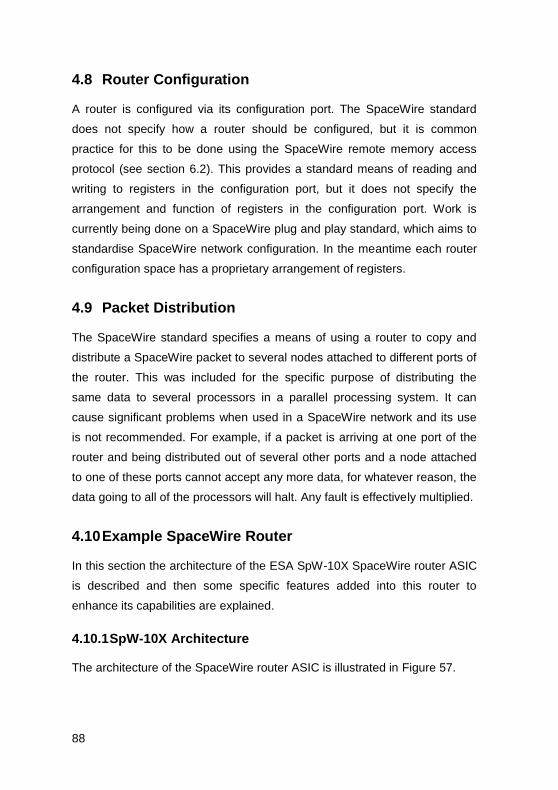
88
4.8 Router Configuration
A router is configured via its configuration port. The SpaceWire standard
does not specify how a router should be configured, but it is common
practice for this to be done using the SpaceWire remote memory access
protocol (see section 6.2). This provides a standard means of reading and
writing to registers in the configuration port, but it does not specify the
arrangement and function of registers in the configuration port. Work is
currently being done on a SpaceWire plug and play standard, which aims to
standardise SpaceWire network configuration. In the meantime each router
configuration space has a proprietary arrangement of registers.
4.9 Packet Distribution
The SpaceWire standard specifies a means of using a router to copy and
distribute a SpaceWire packet to several nodes attached to different ports of
the router. This was included for the specific purpose of distributing the
same data to several processors in a parallel processing system. It can
cause significant problems when used in a SpaceWire network and its use
is not recommended. For example, if a packet is arriving at one port of the
router and being distributed out of several other ports and a node attached
to one of these ports cannot accept any more data, for whatever reason, the
data going to all of the processors will halt. Any fault is effectively multiplied.
4.10 Example SpaceWire Router
In this section the architecture of the ESA SpW-10X SpaceWire router ASIC
is described and then some specific features added into this router to
enhance its capabilities are explained.
4.10.1 SpW-10X Architecture
The architecture of the SpaceWire router ASIC is illustrated in Figure 57.

89
Non-blocking
Crossbar
Switch
Control
Logic Routing
Table
Status/Error
Registers
Configuration
Port
Control
Registers
Status
Outputs
Tick
Counter
Time-Code
Inputs/Outputs
SpW Port 1
SpW Port 2
SpW Port 3
SpW Port 4
SpW Port 5
SpW Port 6
SpW Port 7
SpW Port 8
SpaceWire
Interfaces
External Port
Output FIFO
Input FIFOFIFO Port
Input/Output
External Port
Output FIFO
Input FIFOFIFO Port
Input/Output
Figure 57 ESA SpW-10X SpaceWire Router ASIC Architecture
There are eight SpaceWire ports, two external ports and an internal
configuration port in the SpaceWire router. A low latency, worm-hole routing,
non-blocking, crossbar switch enables packets arriving at any SpaceWire
port, external port or generated in the configuration port to be directed out of
any other SpaceWire or external port or to be routed to the configuration
port.
The SpaceWire ports are compliant with the SpaceWire standard [2]
providing high-speed, bi-directional communications. The FIFO ports each
comprise an input FIFO and an output FIFO and can receive and send data
characters and end of packet markers. A time-code port is also provided
along with a time-counter to facilitate the propagation of time-codes, see
section 5. When a valid time-code arrives at a router port it is sent out of all
the other SpaceWire ports and a TICK_OUT signal is generated at the time-

90
code port. The router can operate as a time-code master using the TICK_IN
provided in the time-code port.
The configuration port is accessible via any of the SpaceWire or external
ports. It contains registers which control the operation of the SpaceWire
ports, external ports and the crossbar switch. The configuration port holds
status registers for the various ports and the switch. These registers can be
read using a configuration read command to determine the status of the
router and to access error information. Status and error information can also
be selected for output on several status pins. The routing table is accessed
via the configuration port. The logical address port mappings and priority
bits can be set in the routing table. The routing table is used to control group
adaptive routing and priority arbitration in the crossbar switch. In the SpW-
10X Router configuration is done using the SpaceWire Remote Memory
Access Protocol (RMAP), see chapter 6.
The SpW-10X was designed by the University of Dundee, transferred to
radiation hard technology by Austrian Aerospace, and is manufactured by
Atmel and sold as the AT7910E device. It is packaged in a space qualified
256 pin QFP package, see Figure 58.
Figure 58 Photograph of SpW-10X Router ASIC

91
4.10.2 Watchdog Timers
Watchdog timers are provided in the SpW-10X on each port to detect
blocking (see section 4.5). If a SpaceWire packet becomes blocked for any
reason the SpW-10X will detect this blockage, append an EEP to the end of
data already sent, and spill the tail end of the packet. A range of time-out
values are provided from 0.1ms to over 1s. The watchdog timers can be
disabled.
4.10.3 Routing to a Not-Connected Port
It is possible that a packet does not have a correct address, or a routing
table is not correctly configured and it ends up being routed to a port that is
not connected to anything. In this situation, if watchdog timers are enabled,
the router will wait for the link to start until the end of the time-out period and
then spill the packet. No EEP is appended since no data from the packet will
have been transferred. If watchdog timers are not enabled, the packet will
be spilt immediately.
4.10.4 Routing to a Non-Existent Port
Similarly a packet could be routed to a port that does not actually exist on
the router, e.g. port 12 on an 8 port router. In this case the router
immediately spills the packet and logs this error in its status registers.
4.10.5 Routing to a Busy Port
If a packet is routed to a port that is already busy on a router, the router will
wait to send the packet for the watchdog timer period. If it times out it will
spill the packet, but not append an EEP to the end of the packet since no
data from the packet has been sent. This is different from the case in
section 4.10.2, as there the packet is in the process of being sent through a
router output port when it becomes blocked. Here the packet has not yet
been switched to the output port, as that port is busy. If the time out occurs
and the waiting packet is spilt, this error is logged in a status register.
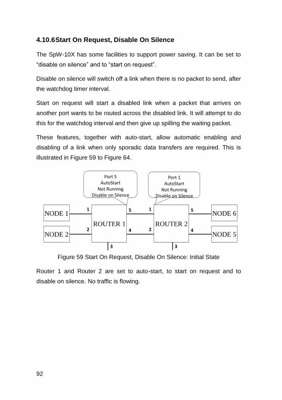
92
4.10.6 Start On Request, Disable On Silence
The SpW-10X has some facilities to support power saving. It can be set to
“disable on silence” and to “start on request”.
Disable on silence will switch off a link when there is no packet to send, after
the watchdog timer interval.
Start on request will start a disabled link when a packet that arrives on
another port wants to be routed across the disabled link. It will attempt to do
this for the watchdog interval and then give up spilling the waiting packet.
These features, together with auto-start, allow automatic enabling and
disabling of a link when only sporadic data transfers are required. This is
illustrated in Figure 59 to Figure 64.
NODE 1
NODE 2
NODE 6
NODE 5
ROUTER 1 ROUTER 2
1
2
5
4
1
2
5
4
33
Port 5AutoStart
Not RunningDisable on Silence
Port 1AutoStart
Not RunningDisable on Silence
Figure 59 Start On Request, Disable On Silence: Initial State
Router 1 and Router 2 are set to auto-start, to start on request and to
disable on silence. No traffic is flowing.

93
NODE 1
NODE 2
NODE 6
NODE 5
ROUTER 1 ROUTER 2
1
2
5
4
1
2
5
4
33
Node 1Sends packet
Figure 60 Start On Request, Disable On Silence: Node Starts to Send
Packet
Node 1 sends a packet to Router 1 which is destined for node 5 and is to be
forwarded out of port 5 of Router 1. This port is disabled at present.
NODE 1
NODE 2
NODE 6
NODE 5
ROUTER 1 ROUTER 2
1
2
5
4
1
2
5
4
33
Port 5 automatically
started
Figure 61 Start On Request, Disable On Silence: Output Port Started
Port 5 of Router 1 is started automatically and attempts to initialise the link
to port 1 of Router 2.

94
NODE 1
NODE 2
NODE 6
NODE 5
ROUTER 1 ROUTER 2
1
2
5
4
1
2
5
4
33
Connection made and packet transferred
Figure 62 Start On Request, Disable On Silence: Connection Made and
Packet Forwarded
Port 1 of Router 2 is set to auto-start, so when Router 1 tries to initialise the
link it succeeds and the packet is forwarded through Router 2 to reach node
5.
NODE 1
NODE 2
NODE 6
NODE 5
ROUTER 1 ROUTER 2
1
2
5
4
1
2
5
4
33
After timoutautomatically
disabled
Figure 63 Start On Request, Disable On Silence: Time-out When Silent
There are no more packets to be sent so the link between Router 1 port 5
and Router 2 port 1 falls silent. After the time-out period. Router 1 detects
that there is no more traffic being sent over this link and since it is set to
disable on silence, it disables output port 5.

95
NODE 1
NODE 2
NODE 6
NODE 5
ROUTER 1 ROUTER 2
1
2
5
4
1
2
5
4
33
Linkpowered down saving power
Figure 64 Start On Request, Disable On Silence: Link Disconnected
Once Router 1 port 5 is disabled, it forces a disconnect to be detected at the
other end of the link. Router 2 port 1 is then disabled. If tri-stating of links is
enabled, power can be saved.
4.10.7 Tristate
The output ports can be put in a state similar to tri-state to save some power
when they are not being used. Remember that an LVDS driver is always
sourcing current. Tri-stating it turns off this current and stops power being
wasted. Tri-state can be used with the power saving techniques mentioned
in section 4.10.6.
4.10.8 Disable Transmit Clocks
The SpW-10X router has eight SpaceWire ports. In some systems not all of
these ports are required. It is then possible to turn off the clock tree to a port
to save power. The front end receive part of the port has its clock derived
from the receive signal so there will be no dynamic power consumed in the
receiver if it is not connected. Configuration registers are used to disable the
transmit clocks to unused ports.
4.10.9 Priority Packet Delivery
Some SpaceWire routers have implemented a priority scheme, although this
is not specified in the SpaceWire standard.

96
If there are two input ports in a router waiting to use a particular output port,
an arbitration mechanism is used to select which input port is to be served.
The arbitration mechanism can include a priority scheme. There is no
priority flag available within the header of a SpaceWire packet to specify its
priority level. The SpaceWire header only contains address information, so
packet priority must be associated with a logical address (or with the input
port number). In the routing tables logical addresses may be assigned high
or low priority. High priority logical addresses have preferential access to an
output port when arbitration takes place. A logical address that has been
assigned high priority, acts as a high priority channel across the network
from many possible sources to the one destination. If high and low priority
access to a particular destination is required, two logical addresses are
required for a particular destination, one assigned high priority and the other
low priority. A source can then decide which logical address to use when
sending a packet to a destination, depending on the required priority of the
packet. There is a compromise between the number of destinations that can
be addressed and the number of priority levels. With two priority levels it is
possible to have, say 128 low priority destinations and 96 high priority
destinations within the 224 logical addresses available.
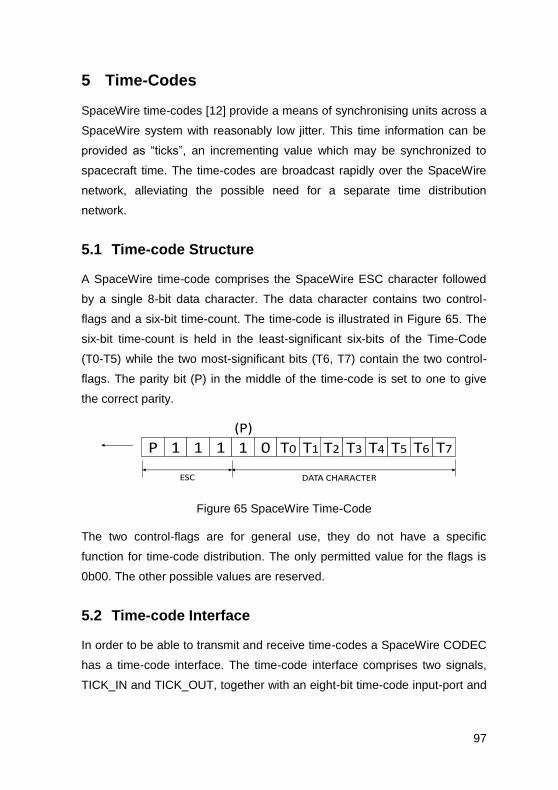
97
5 Time-Codes
SpaceWire time-codes [12] provide a means of synchronising units across a
SpaceWire system with reasonably low jitter. This time information can be
provided as “ticks”, an incrementing value which may be synchronized to
spacecraft time. The time-codes are broadcast rapidly over the SpaceWire
network, alleviating the possible need for a separate time distribution
network.
5.1 Time-code Structure
A SpaceWire time-code comprises the SpaceWire ESC character followed
by a single 8-bit data character. The data character contains two control-
flags and a six-bit time-count. The time-code is illustrated in Figure 65. The
six-bit time-count is held in the least-significant six-bits of the Time-Code
(T0-T5) while the two most-significant bits (T6, T7) contain the two control-
flags. The parity bit (P) in the middle of the time-code is set to one to give
the correct parity.
P 1 1 1 1 0 T0 T1 T2 T3 T4 T5 T6 T7
(P)
ESC DATA CHARACTER
Figure 65 SpaceWire Time-Code
The two control-flags are for general use, they do not have a specific
function for time-code distribution. The only permitted value for the flags is
0b00. The other possible values are reserved.
5.2 Time-code Interface
In order to be able to transmit and receive time-codes a SpaceWire CODEC
has a time-code interface. The time-code interface comprises two signals,
TICK_IN and TICK_OUT, together with an eight-bit time-code input-port and
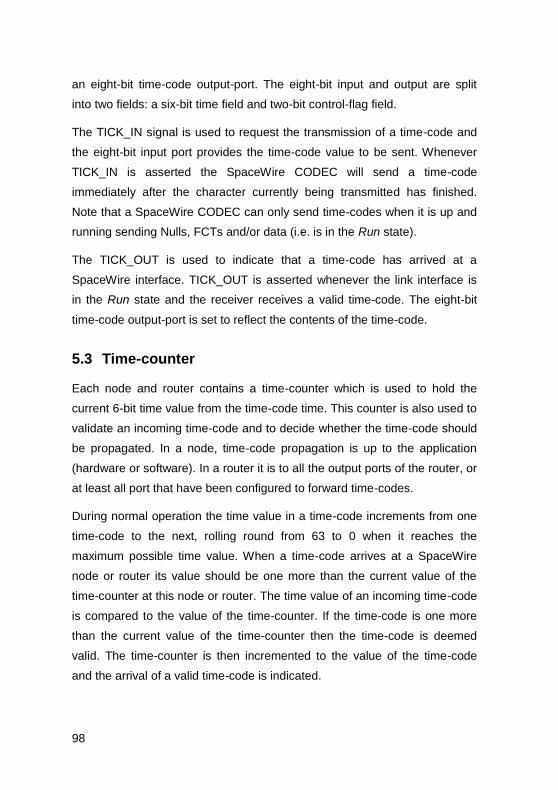
98
an eight-bit time-code output-port. The eight-bit input and output are split
into two fields: a six-bit time field and two-bit control-flag field.
The TICK_IN signal is used to request the transmission of a time-code and
the eight-bit input port provides the time-code value to be sent. Whenever
TICK_IN is asserted the SpaceWire CODEC will send a time-code
immediately after the character currently being transmitted has finished.
Note that a SpaceWire CODEC can only send time-codes when it is up and
running sending Nulls, FCTs and/or data (i.e. is in the Run state).
The TICK_OUT is used to indicate that a time-code has arrived at a
SpaceWire interface. TICK_OUT is asserted whenever the link interface is
in the Run state and the receiver receives a valid time-code. The eight-bit
time-code output-port is set to reflect the contents of the time-code.
5.3 Time-counter
Each node and router contains a time-counter which is used to hold the
current 6-bit time value from the time-code time. This counter is also used to
validate an incoming time-code and to decide whether the time-code should
be propagated. In a node, time-code propagation is up to the application
(hardware or software). In a router it is to all the output ports of the router, or
at least all port that have been configured to forward time-codes.
During normal operation the time value in a time-code increments from one
time-code to the next, rolling round from 63 to 0 when it reaches the
maximum possible time value. When a time-code arrives at a SpaceWire
node or router its value should be one more than the current value of the
time-counter at this node or router. The time value of an incoming time-code
is compared to the value of the time-counter. If the time-code is one more
than the current value of the time-counter then the time-code is deemed
valid. The time-counter is then incremented to the value of the time-code
and the arrival of a valid time-code is indicated.

99
If the time value of the time-code is not one more than the time-counter then
the time-code is not valid. In this case the time-counter is set to the value of
the newly arrived time-code but the arrival of the time-code is not flagged.
5.4 Time Master
A single SpaceWire node or router in a system is responsible for generating
time-codes. This “time-master” has an active TICK_IN signal which is
asserted periodically (e.g. every millisecond) by its host system. Only the
time-master should assert its TICK_IN signal, all other nodes must keep
their TICK_IN signals de-asserted. To send out a time-code the time-master
has to increment the time value on the SpaceWire CODEC time input-port
and then assert the TICK_IN signal. The SpaceWire CODEC will then read
in the new time-code value and transmit the requested time-code as soon
as the current character has finished being sent.
The time-counter in the node or router acting as the time-master, may be
used to generate the correct sequence of time-codes for transmission. The
six-bit time-counter output is fed to the time-code input-port. When the next
time-code is to be transmitted, the time-counter is incremented and the
TICK_IN signal asserted. This causes the SpaceWire CODEC to send the
required time-code. The values of the two control-flags sent in the time-code
are application dependent. Their values should be updated when the time-
counter is incremented.
Time-codes are normally generated periodically by the time-master to
provide a regular timing tick for the SpaceWire system. The frequency of
time-code is called the tick rate and the period between time-codes is called
the tick interval.
5.5 Time-codes across a Link
When one end of a SpaceWire link is periodically sending out valid time-
codes, the SpaceWire interface at the other end of the link receives the

100
time-codes, checks their validity, updates the time-counter with the new time
value and asserts the TICK_OUT signal. The host system attached to this
end of the SpaceWire link, receives periodic TICK-OUT signals together
with the six-bit time value and the two control-flags. The TICK-OUT signal
can be used to raise an interrupt or event in a software-driven node.
If a SpaceWire interface receives a time-code that is not one more than the
current value of its time-counter then the time-code is not valid and the
interface does not emit a TICK_OUT signal.
5.6 Router Action on Receiving a Time-code
A router contains a single time-counter. When a link interface on a router
receives a time-code it checks that it is one more than the current value of
the router’s time-counter. It then increments the router’s time-count and
emits a TICK_OUT signal. This TICK_OUT signal propagates to the
TICK_IN interfaces of all the router output ports so that they all emit the
time-code. This time-code is the same value as that received by the router,
since the router time-counter has been incremented. The time-code is not
emitted by the link that first received the time-code.
If there is a circular connection then the router will receive a time-code with
the same time value as the router time-counter. When this happens the
time-code is ignored. In this way time flows forward through a network
reaching all nodes but is suppressed if it flows back due to a circular
connection.
5.7 Time-code Distribution across a Network
In this section the distribution of time-codes across a SpaceWire network is
described.
The initial state of a network is shown in Figure 66. N1 and N2 are nodes.
R1 and R2 are routers. The dotted lines represent the SpaceWire links
between the nodes and routers. N1 is time-master and sends out a time-

101
code whenever its TICK_IN signal is asserted. The numbers in the node and
router boxes represent the current values of their time-counters.
N1
40
R2
40
R1
40
R3
40
N2
40
Figure 66 Initial State of Network
When TICK_IN is asserted in node N1, its time-counter is incremented from
40 to 41 and a time-code with time value 41 is transmitted. This is shown in
Figure 67.
N1
41
R2
40
R1
40
R3
40
N2
40
TICK_IN
Figure 67 TICK_IN Asserted
The transmitted time-code is received by router R1 which checks that the
time value is one more than the current time counter value, and then
increments its time-counter and sends out time-code on all its other links.
See Figure 68.
N1
41
R2
40
R1
41
R3
40
N2
40
Figure 68 Router R1 Forwards Time-codes

102
Routers R2 and R3 both receive time-codes sent from R1 and both of these
routers send out a time-code on all other links as shown in Figure 69.
N1
41
R2
41R1
41
R3
41
N2
40
Figure 69 Routers R2 and R3 Forward Time-codes
Node N2 receives the time-code from R3 and validates that the incoming
time-code has a time value of one more than the node’s time-counter. It
then increments the time-counter and asserts TICK-OUT. See Figure 70.
Time in N2 is updated.
N141
R241
R141
R341
N241
TICK_OUT
Figure 70 N2 Receives Time-code and Asserts TICK_OUT
R3 will also receive a time-code from R2, which is now not one more than
R3’s time-counter value, so is ignored as shown in Figure 71. This prevents
time-codes from going back through the network. Time-codes move forward
through the network even when there are loops in the network.
N1
41
R2
41R1
41
R3
41
N2
41
Figure 71 Time-codes Cannot Go Backwards
Node N2 will also receive a time-code from R2 which is not one more than
N2’s time-counter value, so is ignored. This prevents multiple triggering of
the TICK_OUT signal as duplicate copies of the time-code which have taken
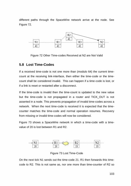
103
different paths through the SpaceWire network arrive at the node. See
Figure 72.
N1
41
R2
41R1
41
R3
41
N2
41
Figure 72 Other Time-codes Received at N2 are Not Valid
5.8 Lost Time-Codes
If a received time-code is not one more than (modulo 64) the current time-
count at the receiving link-interface, then either the time-code or the time-
count shall be considered invalid. This can happen if a time-code is lost, or
if a link is reset or restarted after a disconnect.
If the time-code is invalid then the time-count is updated to the new value
but the time-code is not propagated in a router and TICK_OUT is not
asserted in a node. This prevents propagation of invalid time-codes across a
network. When the next time-code is received it is expected that the time-
counter matches the time-code and normal operation resumes. Recovery
from missing or invalid time-codes will now be considered.
Figure 73 shows a SpaceWire network in which a time-code with a time-
value of 20 is lost between R1 and R2.
N120
R120
R219
N219
Figure 73 Lost Time-Code
On the next tick N1 sends out the time-code 21. R1 then forwards this time-
code to R2. This is not same as, nor one more than time-counter of R2 so

104
R2 updates its time-counter but does not emit the time-code, as shown in
Figure 74.
N121
R121
R221
N219
Figure 74 R2 Time-counter Updated
On the next tick the time-code 22 is sent from N1 to R1, which forwards it on
to R2. At R2 the time-count is now 21, so the incoming time-code is one
more than the time-count hence the time-code is now valid and is
propagated by the router and reaches N2. See Figure 75. When the time-
code reaches N2 it is not one more than N2’s time-count (value 19) so the
time-code is deemed invalid. N2 updates its time count to 22 but does not
give a TICK_OUT.
N122
R122
R222
N222
Figure 75 N2 Time-counter Updated
The next tick will result in the time-code 23 propagating across the network
and N2 will produce a TICK_OUT, as shown in Figure 76.
N123
R123
R223
N223
TICK_OUT
Figure 76 N2 gets Valid Time-code
It takes several ticks to recover from initial error, depending upon the size of
the network.
Note that if there is an alternative path from R1 to R2 the time-code may
propagate successfully through the alternative path so that R2 gets a valid
105
time-code even though one of the time-codes on its way to R2 gets lost.
This provides a first level of fault tolerance for time-code distribution.
Nodes using the time-code distribution function can either use the
TICK_OUT signal as a periodic timing signal or use the value of the time-
count as an indication of the least-significant 6-bits of system time.
As a missing tick results in a timing discrepancy, the TICK_OUT signal
should not be used to increment a counter with the expectation that this
counter always corresponds to the system time. Rather a time-lock
technique should be used where a free running local time-counter is
updated to be an exact multiple of the system tick rate every time the
TICK_OUT signal is asserted. The reason for this is that when using the
TICK_OUT signal as a periodic timing signal the time-code can be missed
so that a TICK_OUT signal is missed. Having said this, SpaceWire signals
running over 10m SpaceWire cable have a good eye diagram and are
unlikely to give rise to any errors.
5.9 Time-code Latency
The accuracy with which system time can be distributed is dependent upon
the number of links over which it is distributed and the operating rate of each
of those links. A delay of at least 14 bit-periods (ESC + data character = 4 +
10 bits) is encountered for each link that the time-code traverses, due to the
time taken for each link-interface on the way to receive a Time-Code. This
gives rise to a time-skew across a network of Tskew = 14.S/A where S is the
number of SpaceWire links traversed and A is the average link operating-
rate. Jitter is also introduced at each link interface due to the variation in
time spent waiting for the transmitter to finish transmitting the current
character or control code. At each link interface a delay of 0 to 10 bit-periods
can be encountered. Across a network, this gives rise to a total jitter of T jitter
= 10.S/A. For an average rate of 100 Mbit/s and 10 links traversed, the time
skew is 1.4 s and the jitter 1.0 s. The skew and jitter may be higher than
indicated above depending on the implementation of the link-interface. A

106
time accuracy across a network of significantly better than 10 s may be
difficult to achieve, using the standard time-code mechanism.
5.10 Time-code Applications
5.10.1 Synchronisation
Time-codes sent periodically may be used to synchronise the operation of a
SpaceWire network, separating time into discrete time-slots during which
scheduled transactions take place.
5.10.2 Time Distribution
With the provision of this basic time distribution function, application level
protocols can be used to distribute specific time values at full resolution (not
just 6-bits) and to issue time dependent commands etc. The two control
flags that are distributed with the 6-bit time code can be used to broadcast
information to all nodes and routers on the network. However, these two
control flags are reserved in the SpaceWire standard, so they should be
both set to zero, to be compliant with the standard.
Nodes using the system time distribution function can either use the
TICK_OUT signal as a periodic timing signal or use the value of the time-
count as an indication of the least-significant 6-bits of system time.
5.10.3 Event Signalling Across A Point-To-Point Link
Time-codes can also be used to signal events or to pass a high-priority byte
of information across a point-to-point link. The time-code is sent
transparently in the middle of the packet currently being transmitted. There
is no need to terminate the current packet or to wait for its transmission to
complete before sending the time-code. This technique should not be used
when there are routers in the SpaceWire network.

107
5.10.4 Multiple Time-codes
NASA Goddard Space Flight Centre used four independent time-code
counters in their routers and interfaces to provide four independent sets of
time-codes indicted by the four possible values of the two flags in the time-
code character. The value of these two flags determined which of the four
time-code counters was used to validate the time-code before it was
forwarded.
This approach allowed four different time signals to be provided over the
SpaceWire network.
5.10.5 Interrupt scheme
Professor Yuriy Sheynin of St Petersburg University of Aerospace
Instrumentation (SUAI) devised a scheme for sending interrupts over
SpaceWire using a time-code like mechanism. Using one of the reserved
values of the time-codes it permitted 32 interrupt signals to be transferred
over the SpaceWire network. This mechanism operates in parallel with the
time-code mechanism.

108
6 SpaceWire Protocols
“SPACEWIRE PROTOCOLS” and other chapters will be
added to the SpaceWire User’s Guide.
Please check www.star-dundee.com for latest updates.
Here is a brief indication of what the SpaceWire Protocols chapter will
contain.
6.1 Protocol Identifier
The protocol identification scheme enables many different protocols to
operate concurrently over a SpaceWire network without them interfering
with each other. Each protocol is given a unique identifier. Units receiving
packets process and respond to them according to the protocol specified by
the protocol identifier in the packet. If a packet arrives with a particular
protocol identifier that is not supported by a node, then it is ignored.
The protocol identification scheme is specified in ECSS standard ECSS-E-
ST-50-51C.
6.2 Remote Memory Access Protocol
The flexibility of SpaceWire means that it can be used in many different
ways to solve an on-board communication need, e.g. configuring and
controlling an instrument. To avoid unnecessary duplication of effort the
SpaceWire Working Group [13] examined these common applications of
SpaceWire and specified some additional protocols, enabling further
standardisation of the on-board data-handing system. The SpaceWire

109
Remote Memory Access Protocol (RMAP) [14] [15], is a particularly
successful example of one of these protocols that operate over SpaceWire.
RMAP provides a common mechanism for reading and writing to registers
and memory in a remote device over a SpaceWire network. It can be used
to configure devices, read housekeeping information, read data from an
instrument or mass-memory, and write data into a mass-memory from an
instrument. Together RMAP and SpaceWire provide a powerful combination
for spacecraft instrument data-handling. A central payload processing
computer is able to configure the instruments using RMAP. When data is
available it can be read from the instrument using an RMAP read command.
A uniform memory space can be provided for each instrument with pages
for instrument data, configuration registers and housekeeping status
registers, simplifying and standardising instrument control operations.
6.3 CCSDS Packet Transfer Protocol
The Consultative Committee for Space Data Systems (CCSDS) Packet
Transfer Protocol (PTP) is designed to transfer CCSDS Space Packets from
one SpaceWire device to another. It encapsulates a CCSDS Space Packet
into a SpaceWire packet, transfers it from the unit initiating the data transfer
to a target device across a SpaceWire network. At the target device the
CCSDS Space Packet is extracted from the SpaceWire packet and passed
to a target user application. This protocol does not provide any means for
ensuring delivery of the packet nor is it responsible for the contents of the
packet being a CCSDS Space Packet.

110
REFERENCES
1. S.M. Parkes, “SpaceWire: The Standard”, Proceedings, DASIA 99,
Data Systems In Aerospace, 17-21 May 1999, Lisbon, Portugal, pp
111-116, European Space Agency (ESA) publication no. SP-447, ISBN
92-9092-788-7.
2. European Cooperation for Space Standardization, Standard ECSS-E-
ST-50-12C, SpaceWire, Links, Nodes, Routers and Networks, Issue 1,
European Cooperation for Space Data Standardization, February 2003
(formerly ECSS-E-50-12A February 2003).
3. ESA SpaceWire Website, http://spacewire.esa.int, viewed on 1st
December 2010.
4. S.M. Parkes and A. Gillions, “DSP Technology Study Final Report”,
British Aerospace Space Systems Ltd, TP 9459, ESTEC Contract
Number 8741/90/NL/JG(SC), September 1992.
5. Inmos Transputer
6. T9000 Transputer User Manual
7. IEEE Computer Society, “IEEE Standard for Heterogeneous
Interconnect (HIC) (Low-Cost, Low-Latency Scalable Serial
Interconnect for Parallel System Construction)”, IEEE Standard 1355-
1995, IEEE, June 1996.
8. S.M. Parkes et al, “Review of Standard and Status”, Digital Interface
Circuit Evaluation Study WP1000 Technical Report, Document No.
UoD-DICE-TN-1000, ESA Contract No. 12693/97/NL/FM, University of
Dundee, July 1998.
9. Telecommunications Industry Association, “Electrical Characteristics of
Low Voltage Differential Signaling (LVDS) Interface Circuits”,
ANSI/TIA/EIA-644-1995, March 1996.

111
10. S.M. Parkes, “High-Speed, Low-Power, Excellent EMC: LVDS for On-
Board Data-handling”, DSP’98, 6th International Workshop on Digital
Signal Processing Techniques for Space Applications, ESTEC,
Noordwijk, The Netherlands, 23-25 September 1998, European Space
Agency (ESA) publication no. WPP-144, paper P16.
11. S.M. Parkes, C. McClements, G. Kempf, S. Fischer and A. Leon,
"SpaceWire Router", in: ISWS International SpaceWire Seminar 2003
(Noordwijk, The Netherlands, 4-5 November (CD Rom) 2003) pp.180-
187.
12. S.M. Parkes, "The operation and uses of the SpaceWire time-code", in:
ISWS International SpaceWire Seminar 2003 (Noordwijk, The
Netherlands, 4-5 November (CD Rom) 2003) pp.223-230.
13. SpaceWire working group website,
http://spacewire.esa.int/WG/SpaceWire/, viewed on 1st December 2010.
14. “SpaceWire – Remote memory access protocol”, European
Cooperation for Space Standardization, ECSS-E-ST-50-51C, Issue 1,
January 2010.
15. S. Mills, S.M. Parkes and N. O’Gribin, “SpaceWire Data-handling with
RMAP”, Data Systems in Aerospace (DASIA), 2007, ISBN 92-9092-
202-8.
16. GAIA, http://spacewire.esa.int/science/gaia, viewed on 1st December
2010.
17. ExoMars, http://exploration.esa.int/science-
e/www/object/index.cfm?fobjectid=46048, viewed on 1st December
2010.
18. BepiColombo Mercury Polar Orbiter,
http://www.esa.int/esaSC/120391_index_0_m.html, viewed on 1st
December 2010.

112
19. Sentinel 1, http://www.esa.int/esaLP/SEMBRS4KXMF_LPgmes_0.html,
viewed on 1st December 2010.
20. Sentinel 2, http://www.esa.int/esaLP/SEMM4T4KXMF_LPgmes_0.html,
viewed on 1st December 2010.
21. Sentinel 3, http://www.esa.int/esaLP/SEMTST4KXMF_LPgmes_0.html,
viewed on 1st December 2010.
22. Sentinel 5, http://www.esa.int/esaLP/SEM3ZT4KXMF_LPgmes_0.html,
viewed on 1st December 2010.
23. SWIFT, http://www.nasa.gov/mission_pages/swift/main/index.html,
viewed on 1st December 2010.
24. NASA, “Lunar Reconnaissance Orbiter website”,
http://www.nasa.gov/mission_pages/LRO/main/index.html, viewed on
1st December 2010.
25. LCROSS, http://lcross.arc.nasa.gov/
26. JWST, “James Webb Space Telescope website”,
http://www.jwst.nasa.gov/
27. MMS, “Magnetospheric Multi-Scale mission website”,
http://mms.space.swri.edu/spacecraft.html
28. GOES-R, “Geostationary Operational Environmental Satellite – R
Series website”, http://www.goes-r.gov/
29. D. Fronterhouse and J. Lyke, “Plug-and-Play Satellite(PnPSat)
Demonstrating the Vision”, Proceedings of 1st International SpaceWire
Conference, Dundee, Scotland, Sept 2007.
30. P. Jaff, G. Clifford and J. Summers, “SpaceWire for Operationally
Responsive Space as part of Tacsat-4”, Proceedings of 1st International
SpaceWire Conference, Dundee, Scotland, Sept 2007.

113
31. BepiColombo Mercury Magnetospheric Orbiter,
http://www.stp.isas.jaxa.jp/mercury/p_mmo.html
32. Astro-H, http://astro-h.isas.jaxa.jp/
33. SPRINT-A, http://www.jaxa.jp/article/interview/vol56/p2_e.html
34. ASNARO,
http://www.usef.or.jp/english/f3_project/asnaro/f3_asnaro.html
35. NEC, NEXTAR,
36. RosCosmos and SpaceWire
37. M. CHilderhouse, “NGP-N ASIC”, Microelectronics Presentation Days
2010, ESTEC, 30th March 2010,
http://microelectronics.esa.int/mpd2010/day1/NGP-
N_for_MPD2010.pdf, viewed on 1st December 2010.
38. B. Dean, R. Warren, and B. Boyes, “RMAP over SpaceWire on the
ExoMars Rover for Direct Memory Access by Instruments to Mass
Memory”, 2nd
International SpaceWire Conference, Nara, Japan, Nov
2008.
39. J.R. Marshall, “Evolution and Applications of System on a Chip
SpaceWire Components for Spacebourne Missions”, 2nd
International
SpaceWire Conference, Nara, Japan, Nov 2008.
40. S.M. Parkes, C. McClements, G. Kempf, S. Fischer, P. Fabry and A.
Leon, “SpaceWire Router ASIC”, Proceedings of 1st International
SpaceWire Conference, Dundee, Scotland, Sept 2007.
41. J. Ilstad, W. Gasti, P. Sinander, and S. Habinc, “SpaceWire Remote
Terminal Controller”, Proceedings of International SpaceWire
Conference, Dundee, Sept 2007.
42. IEEE Computer Society, “IEEE Standard for a High Performance Serial
Bus”, IEEE Standard 1394-1995, IEEE, August 1996

114

115
About the Author:
Steve Parkes is the founder and Chief Executive of STAR-Dundee Limited
and Chair in Spacecraft Electronic Systems at the University of Dundee,
leading the Space Technology Centre.
www.star-dundee.com

116
