some gas dynamic aspects of flow control …mhd.ing.unibo.it/old_proceedings/2005_moscow/moscow...
TRANSCRIPT
SOME GAS DYNAMIC ASPECTS OF FLOW CONTROL BY MW ENERGY DEPOSITION
O.A. Azarova, V.G. Grudnitsky
Computing Center of RAS, Moscow, Russia Yu. F. Kolesnichenko
Institute of High Temperatures RAS, Moscow, Russia
Abstract. The results of numerical modeling on a basis of Euler equations of a thin low-density channel effects on supersonic flow past AD bodies are presented. The investigations include different shapes of bodies and different positions of a low-density channel relatively a body. New results concerning flow structure, stagnation parameters, drag forces, standoff of the bow shock wave and a shape of its front have been obtained. Possibility of essential drag reduction via the vortex generation in the area of shock layer has been established. Regimes of an infinite thin low-density channel are considered, too. Results presented could be useful for understanding the particular gas dynamic processes accompanied the MW energy deposition to the supersonic flow past AD body. Effects obtained could be applied for changing flow parameters and aerodynamic characteristics of AD body for the purpose of flight control improvement.
Introduction and statement of the problem
It is well known that a thin channel of low
density effects essentially on supersonic flow past AD bodies and in some cases it leads to reconstruction of the whole flow [1-8]. The essential effect of the modified flow on the drag force of blunt bodies was established in [1]. In [2] some fundamental features (i.e. the vortex flow generation) of an interaction of space inhomogeneity with a spherical shock layer were determined. In [4-6] the use of this phenomenon for changing aerodynamic characteristics of AD bodies for the purpose of flight control improvement was considered. The explorations of a shock wave interaction with an infinite high temperature thread are close to these investigations (see, for example, [5]).
In this work the gas dynamic effect of a thin longitudinal low-density channel on supersonic flow past AD bodies is considered. This kind of heat channel could be obtained via MW energy injection into a supersonic flow. Situation of an infinite channel is investigated, too. This work continues [6-8] on modeling the effects of the different kinds of energy deposition into supersonic flow past AD bodies for the purpose of flight control improvement. The data agree with the experimental ones for the dynamics of the bow shock wave standoff and the stagnation pressure in the investigations of MW energy interaction with supersonic models [6-10].
Numerical modeling is based on the Euler equations for ideal gas in the divergence form, the ratio of specific heats γ=1.4. The unit of length measure is lн=10-2 m the time and velocity units of measure are, respectively, tн=1.6×10⁻⁵s and uн=6.27×10² m/s. Initial flow parameters corresponded to the normal conditions, the Mach number of oncoming flow was 1.89. On the
entrance boundary the parameters of oncoming flow were used. The boundary conditions had a sense of reflection on the x-axis (if the state of problem includes this type of symmetry) and on the body’s boundaries, and of absence of the reflection on the exit boundaries.
Energy release was modeled as the longitudinal channel of low density ρi, ρi=αρρ0 for 0≤y≤Ri, where Ri is the channel radius, ρ0 is the density in undisturbed flow, αρ - the degree of gas rarefaction in the channel. Other parameters in the channel were equal to those of undisturbed flow. The energy release is assumed to arise in the steady flow at the time moment ti and the time interval of its action is ∆t. The channel may be determined via the initial conditions in the space area or the boundary conditions on the entrance boundary. Space and time channel characteristics were in agreement with the parameters of heat areas obtained experimentally as the results of the MW energy injection in air [6,9,10].
We used the same numerical method as in [6-8]. The method employed is the original two-dimensional analog of the difference scheme [11] based on the approach of increasing difference scheme order of approximation on a minimal stencil [12]. The scheme is conservative and has the second order of approximation in space and in time. The boundary conditions were expressed via flux functions and included into the calculations without breaking the conservative laws in the calculation area.
1. Effect of thin low-density channel of a
limited length on supersonic flow past bodies with wedge projections
Case of detached bow shock wave We consider supersonic flow past bodies
with wedge projections for the case of detached
152

bow shock wave (Fig.1a). The cases of body geometry I, II, III, IV correspond to tgβ=∞ (rectangular body), tgβ=1, tgβ=0.5 and tgβ=2, where β is the angle at the top of the wedge projection.
The low-density channel interacts with the stationary shock wave generating the vortex flow in an area of shock layer [6]. Circulation flow in shock layer for the interaction of different shape space inhomogeneities with a spherical shock layer has been pointed out in [2], too. Flow isochors are
presented in Fig.1. The interaction causes some temporary moving the bow shock wave to the left from its undisturbed stationary position. The standoff increase is more significant for longer channels and the smaller values of αρ (or higher temperature) in the channel. Later the vortex flow moves to the body and is divided near the upper corner of the body for the cases of geometry I and II (tgβ=∞ and 1, Fig.1с, 1е). In the case III (tgβ=0.5) the vortex flow is not dividing (Fig.1g).
After an interaction of the vortex with a
0.0 0.2 0.4 0.6 0.8 1.0 1.2 1.40.0
0.2
IIVIIIIIβ
b
a)
0 0.2 0.4 0.6 0.8 1 1.2 1.40
0.2
0.4
0.6
0.8
0 0.2 0.4 0.6 0.8 1 1.2 1.40
0.2
0.4
0.6
0.8
b) c)
0 0.2 0.4 0.6 0.8 1 1.2 1.40
0.2
0.4
0.6
0.8
0 0.2 0.4 0.6 0.8 1 1.2 1.40
0.2
0.4
0.6
0.8
d) e)
0 0.2 0.4 0.6 0.8 1 1.2 1.40
0.2
0.4
0.6
0.8
0 0.2 0.4 0.6 0.8 1 1.2 1.40
0.2
0.4
0.6
0.8
f) g)
Fig.1. Vortex generation and vortex flow structure near the wedge projection for the case of detached bow shock wave,
ti=6.43, Ri=0.05, αρ=0.4, ∆t=0.8. а) – considered cases of the bodies geometry, b) - t=7.9, c) - t=9.0, d) - t=8.3, e) - t=8.9, f) - t=8.2, g) - t=8.8.
153

rarefaction wave with a center in the body’s corner there arise a strong shock wave in the case I and acoustic waves in the cases II, III. Later the shock wave joins with the bow shock. In an area of the top surface of the body a weak shock wave moving right after the vortex is also seen. Some deformation of the bow shock front is pointed out, the latter being more essential for the longer channels and the smaller values of αρ.
Case of attached bow shock wave
Consider the body geometry with attached bow shock wave for supersonic flow past AD body with tgβ=1/3 (case V). In this case the rectangular part of the body is disposed from x=0.9 to x=1.32. Channel parameters are determined as above (Fig.2). In this case the additional shock wave doesn’t arise and the vortex flow is not divided near the upper corner of the body. Instead of the additional shock wave there arises an acoustic wave moving to the bow shock and another weak shock in an area of the top surface of the body moving right after the vortex. It is seen, that the interaction causes local bow shock wave front deformation and temporary moving the bow shock wave to the left from its undisturbed stationary position. These effects are stronger for the longer channels and the smaller values of αρ.
Analysis of the calculation results
As one of the quantitative criteria of the
MW effect on stationary flow past AD bodies, we have chosen the normal force of the length unit of the wedge F:
lpdlFl
/)(0∫=
Here l is the length of the wedge. Evolution of F in time for the considered cases I – V of bodies geometry for αρ=0.4 is presented in Fig.3.
6.0 8.0 10.0 12.0 14.0
0.4
0.5
0.6
0.7
0.8
0.9
1.0
1.1
I
II
IV
III
t
F
III
IV
V
Fig.3. Dynamics of the drag force F, αρ=0.4.
There are two stages of the force F variance. On the first stage (t<8.0) the force F varies together with the bow shock wave moving from its stationary position. On the next stage (8.0<t<10.5) the significant drag force F decrease is caused by the effect of the vortex flow generation as the result of energy release – bow shock wave interaction. It is seen that the values of drag reduction for the case I (rectangular body) and for the case IV (tgβ=2) are practically the same and are equal approximately 50% to initial values for steady flow. Note that the mechanism of the vortex-body surface interaction is not completely clear yet. The drag reduction has the minimal value for the case V of attached bow shock wave (tgβ=1/3). However it should be noted that the effects are stronger for the smaller values of αρ. We
0 0.2 0.4 0.6 0.8 1 1.20
0.2
0.4
0.6
0.8
1
1.2
1.4
0 0.2 0.4 0.6 0.8 1 1.20
0.2
0.4
0.6
0.8
1
1.2
1.4
a) b)
Fig.2. Vortex generation and vortex flow structure near the wedge projection in the case of attached bow shock wave, ti=6.43, Ri=0.05, αρ=0.4, ∆t=0.8. a) - t=8.0, b) - t=8.5.
154

investigated the behavior of the value of a relative drag reduction δ=(Fst-Fmin)/Fst in the dependence upon sinβ (Fig.4). Here Fst is the value of drag force for undisturbed steady flow. It is seen that the dependence was turned out to be close to linear.
0.2 0.4 0.6 0.8 1.0
0.0
0.2
0.4
0.6
sinβ
δ
Fig.4. Dependence of the relative drag reduction δ upon the angle in the top of the ledge, αρ=0.4.
As a characteristic of the channel-bow shock interaction (i.e. the processes of vortex flow generation) in the shock layer we used the value of circulation
∫∫ −=S
yxb dsuvC )(
in the rectangular area confined by the boundaries of calculation area and the straight-line b (see Fig.1a). Evolution of the circulation Cb for the cases I – III and V is presented in Fig.5. On the fist stage the circulation is linear in time. The maximal time interval of the circulation fall down (the interval of the vortex presence in the area between the bow shock front and the body) is established for a blunt body, the interval decreasing together with β for bodies with wedge projection.
6.0 8.0 10.0 12.0 14.0 16.0
-0.3
-0.2
-0.1
0.0
I
II
III
V
t
Cb
Fig.5. Dynamics of the circulation Cb ; αρ=0.4.
Also we investigated the dynamics of the bow shock wave standoff. Dynamics of the bow shock wave coordinate on the x-axis Xw for the cases I – III, V is presented in Fig.6. In the beginning the value of the standoff rate is defined by the solution of the Riemann problem with the center in the point on the x-axis described in one-dimensional approach the interaction of a shock wave and a contact discontinuity (a boundary of the heat channel). This rate is constant in time in the initial stage of the drag force F reduction (t<7.0) and it depends on the value of αρ. Note that it does not depend neither on the angle β nor on the radius of channel Ri. This conclusion is precise for the flat front of a shock wave (normal to the x-axis). In the calculations we consider the shock front coordinate on the axis of symmetry where the shock front is close to flat. Thus the claim is valid with good accuracy in the initial stage for the cases I – IV. For these cases the computed rate values and theoretical ones differ on the value of some percents. In the case V (attached bow shock wave) the rate is constant in time, too. However, its value differs from the value defined by the Riemann problem because in this case the shock front is not normal. Note that in the cases I and II the bow shock wave coordinate Xw has some oscillations in time after the MW release action and before the stationary regime is achieved.
6.0 8.0 10.0 12.0 14.0 16.0
0.2
0.3
0.4
0.5
0.6
t
X w
III
III
V
Fig.6. Dynamics of the bow shock wave coordinate Xw ; αρ=0.4.
For the cases I – IV (detached bow shock wave) the rate of the standoff change and the rate of the circulation Cb change for t<7.0 turned to be equal. Thus, on the fist (linear) stage the circulation variance (reflecting the vortex intensity) depends on the bow shock wave standoff, i.e. on the value of αρ. The same one can conclude about the drag force initial decrease. Later the drag force fall down is connected with vortex-body’s boundary interaction, the latter being the most significant for a blunt body. It is stronger for the greater values of the ledge corner β for AD bodies with wedge projection.
155
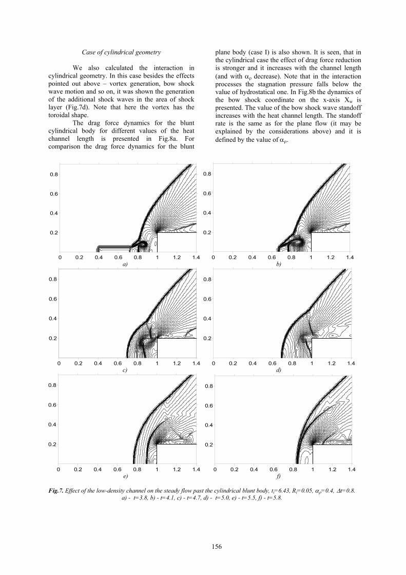
Case of cylindrical geometry
We also calculated the interaction in cylindrical geometry. In this case besides the effects pointed out above – vortex generation, bow shock wave motion and so on, it was shown the generation of the additional shock waves in the area of shock layer (Fig.7d). Note that here the vortex has the toroidal shape.
The drag force dynamics for the blunt cylindrical body for different values of the heat channel length is presented in Fig.8a. For comparison the drag force dynamics for the blunt
plane body (case I) is also shown. It is seen, that in the cylindrical case the effect of drag force reduction is stronger and it increases with the channel length (and with αρ decrease). Note that in the interaction processes the stagnation pressure falls below the value of hydrostatical one. In Fig.8b the dynamics of the bow shock coordinate on the x-axis Xw is presented. The value of the bow shock wave standoff increases with the heat channel length. The standoff rate is the same as for the plane flow (it may be explained by the considerations above) and it is defined by the value of αρ.
0 0.2 0.4 0.6 0.8 1 1.2 1.4
0.2
0.4
0.6
0.8
0 0.2 0.4 0.6 0.8 1 1.2 1.4
0.2
0.4
0.6
0.8
a) b)
0 0.2 0.4 0.6 0.8 1 1.2 1.4
0.2
0.4
0.6
0.8
0 0.2 0.4 0.6 0.8 1 1.2 1.4
0.2
0.4
0.6
0.8
c) d)
0 0.2 0.4 0.6 0.8 1 1.2 1.4
0.2
0.4
0.6
0.8
0 0.2 0.4 0.6 0.8 1 1.2 1.4
0.2
0.4
0.6
0.8
e) f)
Fig.7. Effect of the low-density channel on the steady flow past the cylindrical blunt body, ti=6.43, Ri=0.05, αρ=0.4, ∆t=0.8. a) - t=3.8, b) - t=4.1, c) - t=4.7, d) - t=5.0, e) - t=5.5, f) - t=5.8.
156

Experimental evidence As it follows from above, for
plasmadynamic applications the spatial-elongated kind of plasmoids (air spike, or filament) is needed. Direct experimental evidence of high efficiency of MW filaments use for drag reduction was obtained in recent investigations of MW discharge plasma interaction with supersonic blunt bodies [6-8].
Some characteristic results for airflow Mach number M=2.1 and blunt cylinder AD body are presented in Fig.9. For the first time origination of vortex flow in a shock layer during interaction process was registered [8] (Fig.9a, left – Schlieren images, right – images in chemiluminescence, the digits on the images show the number of microseconds after the MW discharge termination). In Fig.9b the signal from the stagnation point area
2.0 4.0 6.0 8.0 10.0 12.0
0.0
0.4
0.8
1.2
t
F
1 2
3
2.0 4.0 6.0 8.0 10.0 12.0 14
0.2
0.4
0.6
0.8
1.0
1.2
1
2
3
t
Xw
a) b)
Fig.8. Dynamics of the drag force (a) and the bow shock wave position (b) for streamlining the blunt body by the supersoni
with the thin low-density channel, ti=6.43, Ri=0.05, αρ=0.4. Curve 1 – cylindrical symmetry, ∆t=0.8, curve 2 – cylindricsymmetry, ∆t=1.2, curve 3 –plane symmetry, ∆t=0.8.
Fig.9. Interaction of MW filament with 20mm diameter blunt cylinder in airflow with M=2.1.
157
is shown, which is obtained by the pressure sensor, installed inside the model. It is well seen that due to interaction of MW filament with AD-body’s shock layer, pronounced fall down of pressure takes place, the minimal value of it being close to the static pressure in the oncoming undisturbed flow. Such strong interaction was registered for all tested shapes of blunt bodies [8].
Comparison of the calculation and experimental data shows quantitative and for some characteristics qualitative agreement for accordingly chosen relations L/D, where L is the channel length, D is the body diameter.
The value of the characteristic time of an interaction evaluated on experimentally fixed stagnation pressure dynamics and the another value of it obtained as the result of Schlieren images analyses are close to 7.5 of the value of characteristic streamlining time D/u0, where u0 – the velocity of incoming flow. The values are practically equal to those taken from the calculations. Stagnation pressure may fall to the value of hydrostatical one. This fact has been established in the experiments and in the calculations. The maximal value of the bow shock wave standoff in the experiments exceeds its undisturbed stationary value in 1.8 times approximately, the latter being pointed out in the calculations, too. Also, as it was emphasized above the vortex flow generation in the shock layer has been established experimentally and as the result of the calculations. Thus, the calculation model describes adequately the most significant features of the phenomenon registered in the experiments.
Conclusions
We can conclude that MW energy release
qualitative effects on supersonic flow past a blunt body and a body with wedge projection are as follows: − generation of the vortex flow in the area of
shock layer; − motion of the bow shock wave and
deformation of its front; − splitting the vortex flow near the upper corner
of the body (for tgβ ≥1); − arising the additional shock waves with
different mechanisms of generation; − arising the acoustic waves near the upper
corner of the body; − for cylindrical symmetry the effects established
are more stronger than for the plane case; − comparison of the calculation and the
experimental data shows quantitative and for some characteristics qualitative agreement for accordingly chosen relations L/D.
The conclusions on the calculation analyses are:
− possibility of considerable reduction (up to 50%) of the drag force of the wedge projection surface;
− the effects of MW release are stronger for the smaller values of αρ;
− linear form of the dependence of drag reduction upon sinβ;
− beginning drag force variance is caused by the bow shock wave standoff from its undisturbed stationary position;
− in the initial stage the value of standoff rate does not depend on the angle β (for detached bow shock wave) and the radius of channel Ri. It is constant in time and is the same for plane and cylindrical symmetry;
− the most reduction of the drag force is caused by the action of the generated vortex flow, its intensity being more considerable for the smaller values of αρ;
− there exists the time interval in which the effects established do not practically depend on the angle β (for detached bow shock wave), the radius of channel Ri and are defined only by the value of αρ;
− for cylindrical flow symmetry the effects pointed out are more dramatically expressed than for the plane case, for some channel characteristics the stagnation pressure falling below hydrostatical one.
2. Effect of thin low-density channel of
infinite length on supersonic flow past blunt and sharpen bodies with wedge projections
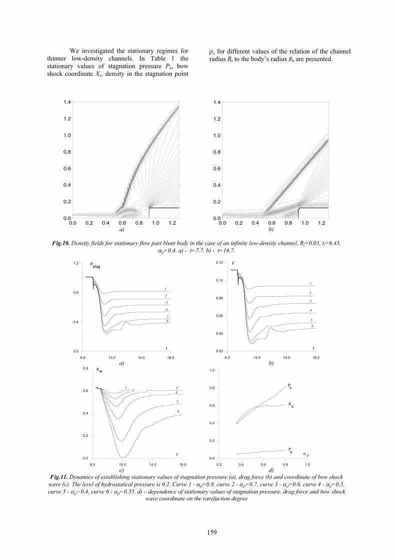
Channel is on flow axis of symmetry Density fields for steady flow past bodies
in the case when a body and an infinite low-density channel are placed symmetrically relatively x-axis are presented in Fig.10. The relation of the channel diameter to the body’s width is 0.25. As it has been shown in [7] for the case of an infinite heat channel the global flow reconstruction takes place before stationary regime is achieved and a vortex flow structure arises in the area of shock layer (Fig.10a). This process is accompanied by the bow shock front deformation and motion from undisturbed stationary position. In steady state the bow shock wave front becomes linear (Fig.10b).
In Fig.11 the dynamics of establishing stationary values of stagnation pressure Pstag (Fig.11а), drag force F, (Fig.11b), and bow shock wave coordinate on x-axis, Xw, (Fig.11c), for different values of αρ and Ri=0.03 is presented. It turned out that the dependences of the stationary values of stagnation pressure Ps and drag force Fs on αρ are close to linear (Fig.11d).
158
We investigated the stationary regimes for thinner low-density channels. In Table 1 the stationary values of stagnation pressure Ps, bow shock coordinate Xs, density in the stagnation point
ρs for different values of the relation of the channel radius Ri to the body’s radius Rb are presented.
0.0 0.2 0.4 0.6 0.8 1.0 1.20.0
0.2
0.4
0.6
0.8
1.0
1.2
1.4
0.0 0.2 0.4 0.6 0.8 1.0 1.20.0
0.2
0.4
0.6
0.8
1.0
1.2
1.4
a) b)
Fig.10. Density fields for stationary flow past blunt body in the case of an infinite low-density channel, Ri=0.03, ti=6.43,
αρ=0.4. a) - t=7.7, b) - t=16.7.
6.0 10.0 14.0 18.0
0.0
0.4
0.8
1.2
1
2
3
4
56
t
Pstag
6.0 10.0 14.0 18.0
0.02
0.04
0.06
0.08
0.10
0.12 F
t
1
2
3
4
56
a) b)
6.0 10.0 14.0 18.0
0.0
0.2
0.4
0.6
0.8
12 3
4
5
6
Xw
t
0.2 0.4 0.6 0.8 1.0
0.0
0.2
0.4
0.6
0.8
1.0
Ps
Xs
Fs α ρ
c) d)
Fig.11. Dynamics of establishing stationary values of stagnation pressure (a), drag force (b) and coordinate of bow shock wave (c). The level of hydrostatical pressure is 0.2. Curve 1 - αρ=0.8, curve 2 - αρ=0.7, curve 3 - αρ=0.6, curve 4 - αρ=0.5, curve 5 - αρ=0.4, curve 6 - αρ=0.35. d) – dependence of stationary values of stagnation pressure, drag force and bow shock
wave coordinate on the rarefaction degree
159
0.0 0.2 0.4 0.6 0.8 1.0 1.2 1.4 1.60.0
0.2
0.4
0.6
0.8
1.0
1.2
1.4
1.6
1.8
2.0
2.2
0.0 0.2 0.4 0.6 0.8 1.0 1.2 1.4 1.60.0
0.2
0.4
0.6
0.8
1.0
1.2
1.4
1.6
1.8
2.0
2.2
a) b)
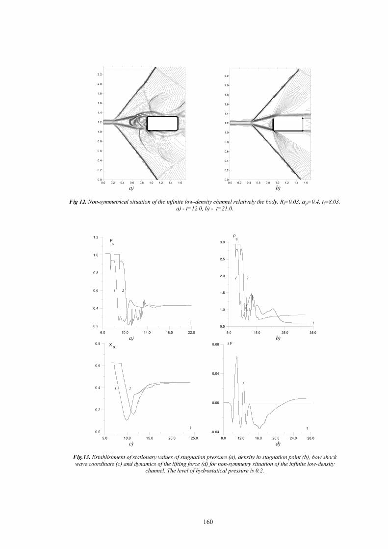
Fig 12. Non-symmetrical situation of the infinite low-density channel relatively the body, Ri=0.03, αρ=0.4, ti=8.03.
a) - t=12.0, b) - t=21.0.
6.0 10.0 14.0 18.0 22.0
0.2
0.4
0.6
0.8
1.0
1.2Ps
t
1 2
5.0 15.0 25.0 35.0
0.5
1.0
1.5
2.0
2.5
3.0
21
t
ρs
а) b)
5.0 10.0 15.0 20.0 25.0
0.0
0.2
0.4
0.6
0.8
1 2
t
X s
8.0 12.0 16.0 20.0 24.0 28.0
-0.04
0.00
0.04
0.08
t
Fδ
с) d)
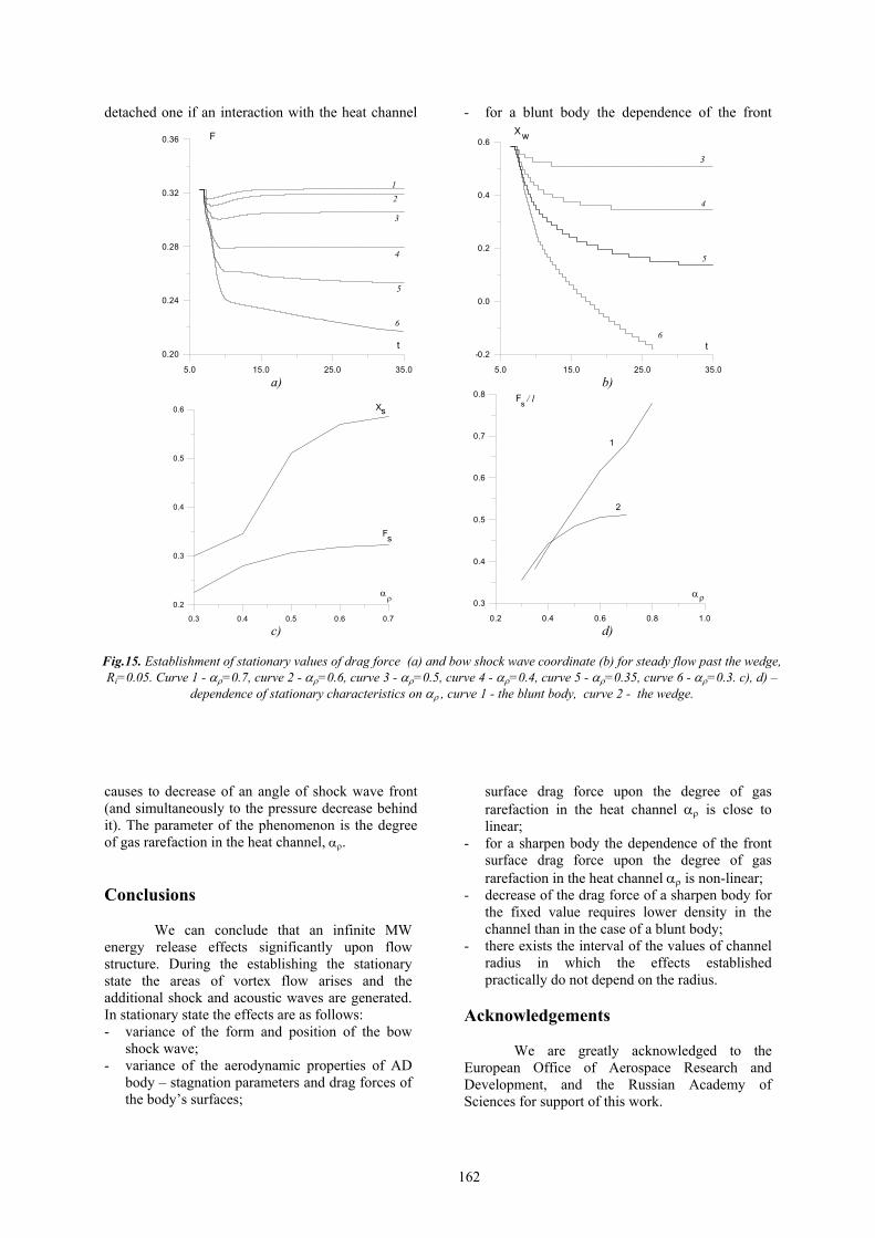
Fig.13. Establishment of stationary values of stagnation pressure (a), density in stagnation point (b), bow shock wave coordinate (c) and dynamics of the lifting force (d) for non-symmetry situation of the infinite low-density
channel. The level of hydrostatical pressure is 0.2.
160

Table1. Ri/ Rb Ps Xs ρs
0.125 0.49 0.54 0.85 0.167 0.43 0.47 0.45 0.208 0.42 0.45 0.53 0.250 0.43 0.46 0.61
It is seen that for the values of the relation
in the interval (0.125, 0.25) the values of Ps and Xs do not practically depend on the relation, the values of ρs differ less then by 10%. The value ρs =0.85, on our opinion, is overstate in connection with the numerical erosion of the contact discontinuity (the heat channel boundary).
Channel placed out of axis of symmetry
We considered non-symmetrical situation of an
infinite low-density channel relatively a body, too. Here the relation of the channel diameter to the body width is, as above, 0.25. Flow picture in isochors is presented in Fig.12. Before the stationary regime is achieved the complicated vortex flow structure arises and it is seen some acoustic waves (or week shock waves for some entrance parameters) near the upper body surface. Stagnation pressure makes some oscillations in time before the stationary state establishes, and the same behavior of the drag force is pointed out, too (Fig.13а, 13b). In stationary state the values of stagnation pressure and bow shock wave coordinate differ to a very small degree from ones for symmetric situation of an infinite low-density channel (Fig.13а, 13c). The values of density in the stagnation point differ more considerably. This fact indicates some decrease of stagnation temperature for non-symmetrical situation of the
low-density channel (Fig.13b). Besides, the lifting force of constant action arising is possible, its value being greater for the smaller values of αρ (Fig.13d).
Stationary flow past a wedge Consider the stationary flow past the wedge
with the value of top angle 18.4o. Here Ri=0.05, ti=6.43, αρ=0.35 (Fig.14). As well known, an attached bow shock wave is formed in the situation of undisturbed steady flow. In the case of an infinite energy release action the flow picture changes. Shock wave moves from undisturbed stationary position and its front is suffered by some fracture (Fig.14a). Later the stationary regime is established, where the bow shock wave is not an attached one. However, its front is linear, too, but the new angle to x-axis is established.
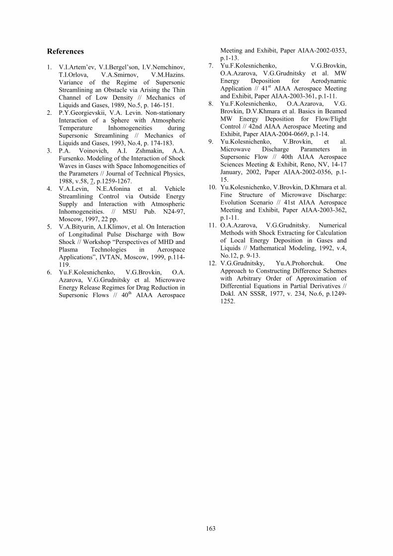
Dynamics of the drag force of the wedge surface F and the bow shock wave coordinate Xw during the steady state establishing for different values of αρ is presented in Fig.15. In this case the dependence of stationary value of drag force Fs on αρ is non-linear (Fig.15c). In Fig.15d dependences of the values of Fs, related to the length of front surface of the blunt body (curve 1) and of the wedge (curve 2) are presented. The relative value of the drag force of a sharpen body in stationary state increases more slowly than in the case of a blunt body. Thus, the decrease of the drag force of a sharpen body for the fixed value requires lower density in the heat channel than in the case of a blunt body.
As the result we can conclude that drag force decrease in the case of a sharpen body has place only if a bow shock wave becomes detached. Criterion of that is as follows [7]. An attached bow shock wave moves from AD body and becomes a
0 0.2 0.4 0.6 0.8 1 1.20
0.2
0.4
0.6
0.8
1
1.2
0 0.2 0.4 0.6 0.8 1 1.20
0.2
0.4
0.6
0.8
1
1.2
a) b)
Fig.14. Steady flow past the wedge in the case of the infinite low-density channel, isochors, Ri=0.05. a) - t=8.0, b) - t=35.0.
161
detached one if an interaction with the heat channel
causes to decrease of an angle of shock wave front (and simultaneously to the pressure decrease behind it). The parameter of the phenomenon is the degree of gas rarefaction in the heat channel, αρ.
Conclusions
We can conclude that an infinite MW energy release effects significantly upon flow structure. During the establishing the stationary state the areas of vortex flow arises and the additional shock and acoustic waves are generated. In stationary state the effects are as follows: - variance of the form and position of the bow
shock wave; - variance of the aerodynamic properties of AD
body – stagnation parameters and drag forces of the body’s surfaces;
- for a blunt body the dependence of the front
surface drag force upon the degree of gas rarefaction in the heat channel αρ is close to linear;
- for a sharpen body the dependence of the front surface drag force upon the degree of gas rarefaction in the heat channel αρ is non-linear;
- decrease of the drag force of a sharpen body for the fixed value requires lower density in the channel than in the case of a blunt body;
- there exists the interval of the values of channel radius in which the effects established practically do not depend on the radius.
Acknowledgements
We are greatly acknowledged to the
European Office of Aerospace Research and Development, and the Russian Academy of Sciences for support of this work.
5.0 15.0 25.0 35.0
0.20
0.24
0.28
0.32
0.36
t
F
12
3
4
5
6
5.0 15.0 25.0 35.0
-0.2
0.0
0.2
0.4
0.6
6
5
3
4
t
X w
а) b)
0.3 0.4 0.5 0.6 0.7
0.2
0.3
0.4
0.5
0.6 Xs
Fs
αρ
0.2 0.4 0.6 0.8 1.0
0.3
0.4
0.5
0.6
0.7
0.8
αρ
1
2
Fs / l
c) d)
Fig.15. Establishment of stationary values of drag force (a) and bow shock wave coordinate (b) for steady flow past the wedge, Ri=0.05. Curve 1 - αρ=0.7, curve 2 - αρ=0.6, curve 3 - αρ=0.5, curve 4 - αρ=0.4, curve 5 - αρ=0.35, curve 6 - αρ=0.3. c), d) –
dependence of stationary characteristics on αρ , curve 1 - the blunt body, curve 2 - the wedge.
162
References
1. V.I.Artem’ev, V.I.Bergel’son, I.V.Nemchinov, T.I.Orlova, V.A.Smirnov, V.M.Hazins. Variance of the Regime of Supersonic Streamlining an Obstacle via Arising the Thin Channel of Low Density // Mechanics of Liquids and Gases, 1989, No.5, p. 146-151.
2. P.Y.Georgievskii, V.A. Levin. Non-stationary Interaction of a Sphere with Atmospheric Temperature Inhomogeneities during Supersonic Streamlining // Mechanics of Liquids and Gases, 1993, No.4, p. 174-183.
3. P.A. Voinovich, A.I. Zshmakin, A.A. Fursenko. Modeling of the Interaction of Shock Waves in Gases with Space Inhomogeneities of the Parameters // Journal of Technical Physics, 1988, v.58, 7, p.1259-1267.
4. V.A.Levin, N.E.Afonina et al. Vehicle Streamlining Control via Outside Energy Supply and Interaction with Atmospheric Inhomogeneities. // MSU Pub. N24-97, Moscow, 1997, 22 pp.
5. V.A.Bityurin, A.I.Klimov, et al. On Interaction of Longitudinal Pulse Discharge with Bow Shock // Workshop “Perspectives of MHD and Plasma Technologies in Aerospace Applications”, IVTAN, Moscow, 1999, p.114-119.
6. Yu.F.Kolesnichenko, V.G.Brovkin, O.A. Azarova, V.G.Grudnitsky et al. Microwave Energy Release Regimes for Drag Reduction in Supersonic Flows // 40th AIAA Aerospace
Meeting and Exhibit, Paper AIAA-2002-0353, p.1-13.
7. Yu.F.Kolesnichenko, V.G.Brovkin, O.A.Azarova, V.G.Grudnitsky et al. MW Energy Deposition for Aerodynamic Application // 41st AIAA Aerospace Meeting and Exhibit, Paper AIAA-2003-361, p.1-11.
8. Yu.F.Kolesnichenko, O.A.Azarova, V.G. Brovkin, D.V.Khmara et al. Basics in Beamed MW Energy Deposition for Flow/Flight Control // 42nd AIAA Aerospace Meeting and Exhibit, Paper AIAA-2004-0669, p.1-14.
9. Yu.Kolesnichenko, V.Brovkin, et al. Microwave Discharge Parameters in Supersonic Flow // 40th AIAA Aerospace Sciences Meeting & Exhibit, Reno, NV, 14-17 January, 2002, Paper AIAA-2002-0356, p.1-15.
10. Yu.Kolesnichenko, V.Brovkin, D.Khmara et al. Fine Structure of Microwave Discharge: Evolution Scenario // 41st AIAA Aerospace Meeting and Exhibit, Paper AIAA-2003-362, p.1-11.
11. O.A.Azarova, V.G.Grudnitsky. Numerical Methods with Shock Extracting for Calculation of Local Energy Deposition in Gases and Liquids // Mathematical Modeling, 1992, v.4, No.12, p. 9-13.
12. V.G.Grudnitsky, Yu.A.Prohorchuk. One Approach to Constructing Difference Schemes with Arbitrary Order of Approximation of Differential Equations in Partial Derivatives // Dokl. AN SSSR, 1977, v. 234, No.6, p.1249-1252.
163