thermodynamic and gas dynamic aspects of a bleve · thermodynamic and gas dynamic aspects of a...
TRANSCRIPT
Thermodynamic and gas dynamicaspects of a BLEVE
by
Xie Mengmeng
Supervised
by
Dirk Roekaerts and Mark Tummers
Draft No.: 04-200708
Department of Multi-Scale Physics
Faculty of Applied Sciences
Delft University of Technology
The Netherlands
October 1, 2007
Contents
Nomenclature 4
1 Introduction 91.1 Superheated State and Bubble Nucleation . . . . . . . . . . . . . . . . . . 10
1.1.1 Superheated liquid and superheat limit . . . . . . . . . . . . . . . . 101.1.2 Bubble nucleation . . . . . . . . . . . . . . . . . . . . . . . . . . . . 11
1.2 BLEVE as a hazard . . . . . . . . . . . . . . . . . . . . . . . . . . . . . . . 131.2.1 BLEVE . . . . . . . . . . . . . . . . . . . . . . . . . . . . . . . . . 131.2.2 Tunnel safety . . . . . . . . . . . . . . . . . . . . . . . . . . . . . . 141.2.3 Causes for BLEVE . . . . . . . . . . . . . . . . . . . . . . . . . . . 14
1.3 What are the key elements of a BLEVE ? . . . . . . . . . . . . . . . . . . 151.3.1 BLEVE: physical or chemical . . . . . . . . . . . . . . . . . . . . . 151.3.2 BLEVE: hot and cold . . . . . . . . . . . . . . . . . . . . . . . . . . 161.3.3 BLCBE: a new BLEVE . . . . . . . . . . . . . . . . . . . . . . . . 171.3.4 Conclusion: criteria for defining BLEVE . . . . . . . . . . . . . . . 18
1.4 BLEVE stage and BLEVE event . . . . . . . . . . . . . . . . . . . . . . . 191.4.1 Definitions . . . . . . . . . . . . . . . . . . . . . . . . . . . . . . . . 201.4.2 Three stages of a BLEVE event . . . . . . . . . . . . . . . . . . . . 201.4.3 Features of three stages . . . . . . . . . . . . . . . . . . . . . . . . . 20
1.5 Summary . . . . . . . . . . . . . . . . . . . . . . . . . . . . . . . . . . . . 21
2 Theories of Bubble vaporization 232.1 Classical theory for spherical bubble dynamics . . . . . . . . . . . . . . . . 232.2 Homogeneous nucleation theory . . . . . . . . . . . . . . . . . . . . . . . . 26
2.2.1 Extended homogeneous nucleation theory . . . . . . . . . . . . . . 272.2.2 Non-classical method on homogeneous nucleation . . . . . . . . . . 29
2.3 Kinetic theory analysis of explosive boiling of a superheated droplet . . . . 302.4 Summary . . . . . . . . . . . . . . . . . . . . . . . . . . . . . . . . . . . . 32
3 The BLEVE event 343.1 Pre-BLEVE stage . . . . . . . . . . . . . . . . . . . . . . . . . . . . . . . . 34
3.1.1 Crack development . . . . . . . . . . . . . . . . . . . . . . . . . . . 353.1.2 Vessel over-pressure . . . . . . . . . . . . . . . . . . . . . . . . . . . 36
2
Draft No.: 04-200708 October 1, 2007
3.1.3 Liquid/mixture discharge rate . . . . . . . . . . . . . . . . . . . . . 403.1.4 Boiling front propagation . . . . . . . . . . . . . . . . . . . . . . . . 413.1.5 Tank in pool fire engulfment . . . . . . . . . . . . . . . . . . . . . . 443.1.6 Open question in pre-BLEVE stage . . . . . . . . . . . . . . . . . . 45
3.2 BLEVE stage . . . . . . . . . . . . . . . . . . . . . . . . . . . . . . . . . . 453.2.1 Superheat limit and BLEVE . . . . . . . . . . . . . . . . . . . . . . 463.2.2 Prediction of the superheat limit . . . . . . . . . . . . . . . . . . . 473.2.3 Bubble growth at the superheat limit . . . . . . . . . . . . . . . . . 483.2.4 Heterogeneous nucleation factor . . . . . . . . . . . . . . . . . . . . 503.2.5 Numerical simulations for BLEVE stage . . . . . . . . . . . . . . . 523.2.6 Open questions in BLEVE stage . . . . . . . . . . . . . . . . . . . . 57
3.3 Post-BLEVE stage . . . . . . . . . . . . . . . . . . . . . . . . . . . . . . . 573.4 Summary . . . . . . . . . . . . . . . . . . . . . . . . . . . . . . . . . . . . 57
4 Equations and models for two-phase flow 584.1 Conservative equations . . . . . . . . . . . . . . . . . . . . . . . . . . . . . 59
4.1.1 Simplified conservative equations: EVET model . . . . . . . . . . . 594.1.2 Simplified conservative equations: EVUT model . . . . . . . . . . . 60
4.2 Constitutive models . . . . . . . . . . . . . . . . . . . . . . . . . . . . . . . 614.2.1 Interfacial source terms . . . . . . . . . . . . . . . . . . . . . . . . . 614.2.2 Wall source terms . . . . . . . . . . . . . . . . . . . . . . . . . . . . 63
4.3 Specific models . . . . . . . . . . . . . . . . . . . . . . . . . . . . . . . . . 644.3.1 Acoustic volume source term . . . . . . . . . . . . . . . . . . . . . . 644.3.2 Crack opening and choked flow . . . . . . . . . . . . . . . . . . . . 654.3.3 Bubble breakup model . . . . . . . . . . . . . . . . . . . . . . . . . 664.3.4 Slip velocity model . . . . . . . . . . . . . . . . . . . . . . . . . . . 67
Bibliography 68
3
Draft No.: 04-200708 October 1, 2007
NOMENCLATURE
Upper-case Roman
A Surface area
Ai Interfacial area density, [m2/m3]
Ca Capilary number
D Thermal diffusivity
Gb Gibbs number
J Nucleation rate
Ja Jacob number
Je Evaporation rate
N Number of molecules per unit volume
Nu Nusselt number
NA Avogadro constant
Pr Prandtl number
R Bubble radius
R Bubble radius growth rate
R Universal gas constant
R Specific gas constant, R/mM
Re Reynolds number
T Absolute temperature, [Kelvin]
V Volume, [m3]
W Work
Wmin Minimum work of formation of a bubble
W ∗min Minimum work of formation of a critical bubble
Z The elevation
Z Compressibility
Lower-case Roman
c Speed of sound
cp Constant pressure specific heat
cv Constant volume specific heat
4
Draft No.: 04-200708 October 1, 2007
f Friction force
g The gravitational acceleration
h Enthalpy
h Heat transfer coefficient
hLG Latent heat of vaporization
k Thermal conductivity
kB Boltzmann constant
mM Molar mass
mm Molecular mass
n Number density
p Pressure
q Heat
q Heat transfer rate
q′′ Heat transer rate per square meter
r radial distance
r∗ Critical bubble radius
s Entropy
t Time
u Velocity
v Specific volume
Upper-case Greek
Ω Solid angle of the laser lens
Γ Mass transfer rate
Γ′′ mass transfer rate per square meter
Lower-case Greek
αc Condensation coefficient
αl Liquid volume fraction
αv Void fraction, vapor volume fraction
β Physical variable in [23]
γ Specific heat ratio, isentropic component, cp/cv
θ Fraction factor
5
Draft No.: 04-200708 October 1, 2007
λ Physical variable in [23]
µ Chemical potential
ν Kinetic viscosity
ξ Contact angle at the bubble surface
ρ Density
σ Surface tension
τ Time variable in [23]
φ Heterogeneous nucleation factor
ϕ Liquid-to-vapour volume expansion factor
χ Flash fraction
ψ Perimeter
6
Draft No.: 04-200708 October 1, 2007
Superscripts
∗ Parameters for critial bubble
1ph One-phase
2ph Two-phase
Subscripts
in general
0 Initial state
B Boiling
b Bubble
bb Bubble boundary
c Critical
h Isenthalpy
i Interface
L left
l Liquid
m Mixture
NU Nucleation
R Right
SL Superheat Limit
s Isentropy
v Vapor
w Wall
∞ Infinity or ambient
crk Crack
frt Boiling front
ini Initial
max Maximum
min Minimum
sat Saturation
thr Threshold
tpl Thermal protection layer
7
Draft No.: 04-200708 October 1, 2007
Abbreviations
BCE The energy per unit volume transferred to the vapor when the liquid flashes [12]
BLCBE Boiling Liquid Compressed Bubble Explosion
BLEVE Boiling Liqid Expanding Vapor Explosion
EOS Equation of State
MI Mechanical Impact
EF External Fire
PLG Pressure Liquefied Gas
PRV Pressure Relief Valve
TLOC Total Loss of Confinement
8
Chapter 1
Introduction
This first chapter will give an introduction to what is a BLEVE, Boiling Liquid ExpandingVapor Explosion, and its hazards particularly in relation to tunnel safety. It will be shownthat several definitions of a BLEVE can be given, depending on the aspect put in focus.In particular distinction can be made between two groups of references, respectively givingan engineering definition and a physical definition. As a result of our literature survey,our own definition of BLEVE will be presented trying to bridge the gap between these twogroups of definitions. In the following chapters, we stick to that definition unless specifiedotherwise.
First of all, we would like to consider some basic concepts, i.e. superheated liquid, explosiveboiling and bubble nucleations, by an easy example.
It is well known that when we heat the water in a tea kettle up to the temperature of100 C at the atmospheric pressure, the water will start to boil or vaporize. In this case,invisible active nuclei formed on the inner surface of the kettle or at any impurities in thewater will grow to be a visible bubble which will detach from the wall and move upwardsdue to buoyancy. Such a type of bubble nucleation is called heterogeneous nucleation sincethe bubble nucleation only occurs at the locations where there is a boundary between twodifferent phases.
However if we put the water into a very smooth glass and heat it in the microoven, theboiling will not occur even the temperature already exceeds the normal boiling point atthe atmospheric pressure. At this moment, the water is said to be superheated and if wekeep heating the water, a rapid ’explosive-like’ boiling, termed explosive boiling, will sud-denly occur and may cause serious damage to the microoven. In this explosive boiling, theactive nuclei are evenly formed throughout the liquid, therefore it is called homogeneousnucleation.
Superheating sometimes is referred to as boiling retardation, or boiling delay. It refers tothe phenomenon in which a liquid is heated to a temperature higher than its boiling point,
9
Draft No.: 04-200708 October 1, 2007
without actually boiling. A superheated state can also be reached in another way than byheating, namely by depressurization to a pressure lower than the saturation pressure atthe prevailing temperature.
The references in this chapter include: [3], [4], [5], [7], [14], [16], [19], [21], [24], [25], [26],[31], [33], [35], [36].
1.1 Superheated State and Bubble Nucleation
1.1.1 Superheated liquid and superheat limit
In physics, a liquid is said to be superheated when its temperature exceeds its saturationtemperature of its pressure or its pressure decreases below its saturation pressure of itstemperature while the liquid is still not boiling.
Tl > Tsat(Pl) or Pl < Psat(Tl)
In this report, the term ’superheating’ refers to the fact of reaching a superheated state,by either of the two methods, rising the temperature or rapid lowering of the pressure andthe reader should bear in mind that superheating does not always involves adding heat.
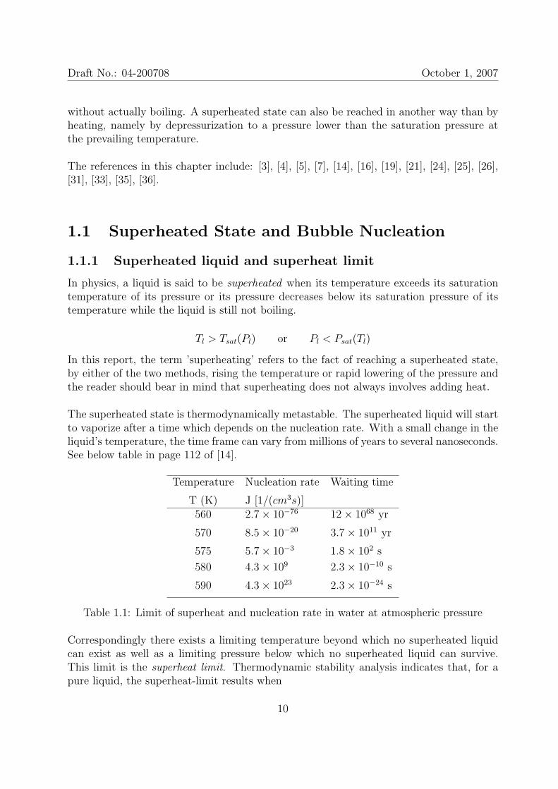
The superheated state is thermodynamically metastable. The superheated liquid will startto vaporize after a time which depends on the nucleation rate. With a small change in theliquid’s temperature, the time frame can vary from millions of years to several nanoseconds.See below table in page 112 of [14].
Temperature Nucleation rate Waiting time
T (K) J [1/(cm3s)]560 2.7× 10−76 12× 1068 yr
570 8.5× 10⁻²⁰ 3.7× 10¹¹ yr
575 5.7× 10⁻³ 1.8× 10² s
580 4.3× 10⁹ 2.3× 10⁻¹⁰ s
590 4.3× 10²³ 2.3× 10⁻²⁴ s
Table 1.1: Limit of superheat and nucleation rate in water at atmospheric pressure
Correspondingly there exists a limiting temperature beyond which no superheated liquidcan exist as well as a limiting pressure below which no superheated liquid can survive.This limit is the superheat limit. Thermodynamic stability analysis indicates that, for apure liquid, the superheat-limit results when
10
Draft No.: 04-200708 October 1, 2007
(∂p∂v
)T
= 0 (1.1)
In this report, we will use TSL and PSL to represent the superheat limit temperature andthe corresponding superheat limit pressure, respectively. Not only the nucleation rate, butalso the bubble growth rate depend on how far away the system is from the superheat limit.
Therefore when a liquid is highly superheated, quite differently from our previous knowl-edge of the normal boiling, the vaporization will commence and proceed in an much shortertime frame. The output is often an ’explosive’ boiling which means the rapid volume ex-pansion of the liquid-to-vapor phase transition can be hazardous.
The process of rapid phase transition from highly superheated liquid to vapor is calledexplosive boiling [31]. Explosive boiling occurs when the liquid is suddenly and drasticallyheated by immersion in a hot medium, or by laser heating, or by passage through a shockwave, or by sudden depressurization as in liquid ejected in space.
So the next question is, what makes the boiling so explosive?
1.1.2 Bubble nucleation
The answer to the question in the previous section is complex, however bubble nucleationis definitely the first aspect that should be qualitatively explained.
Before that, the general progress of bubble growth will be introduced.
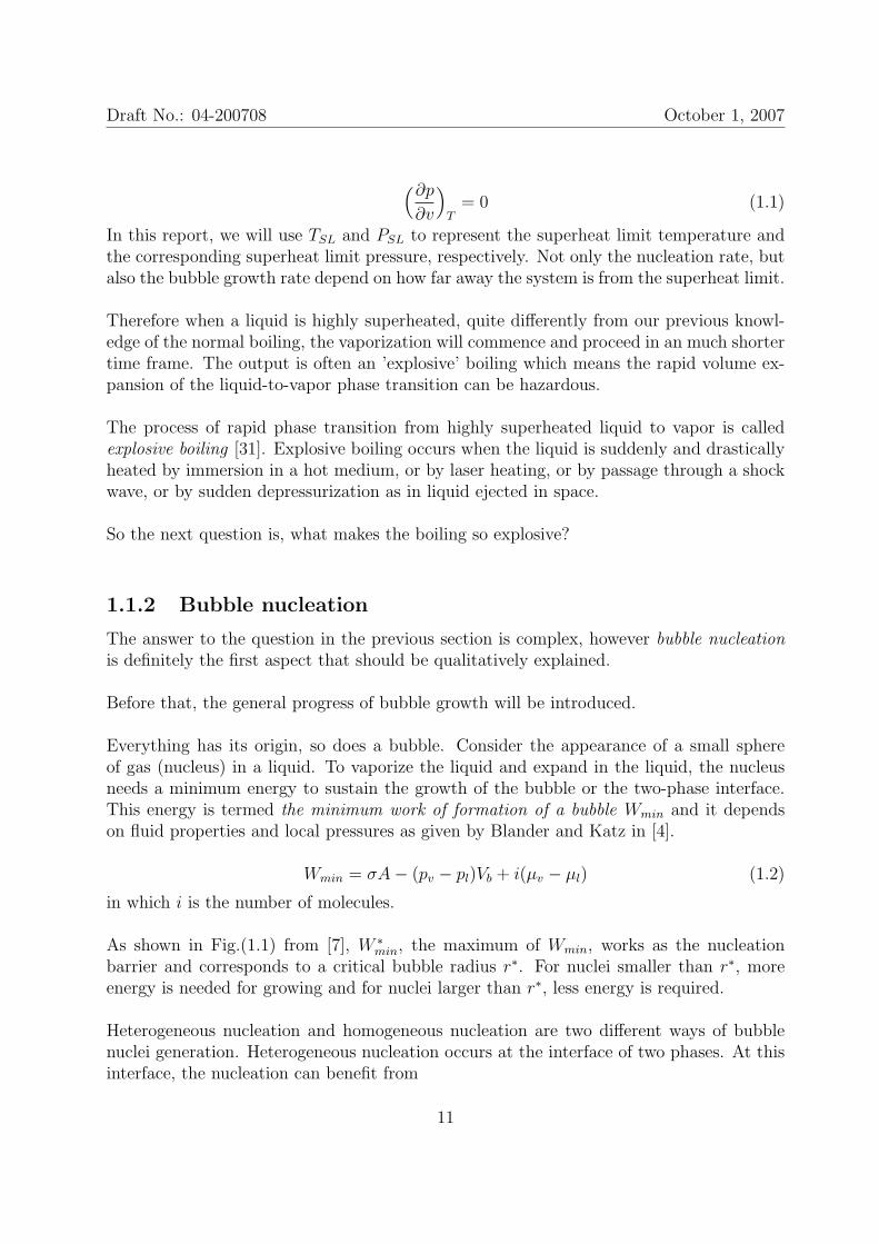
Everything has its origin, so does a bubble. Consider the appearance of a small sphereof gas (nucleus) in a liquid. To vaporize the liquid and expand in the liquid, the nucleusneeds a minimum energy to sustain the growth of the bubble or the two-phase interface.This energy is termed the minimum work of formation of a bubble Wmin and it dependson fluid properties and local pressures as given by Blander and Katz in [4].
Wmin = σA− (pv − pl)Vb + i(µv − µl) (1.2)
in which i is the number of molecules.
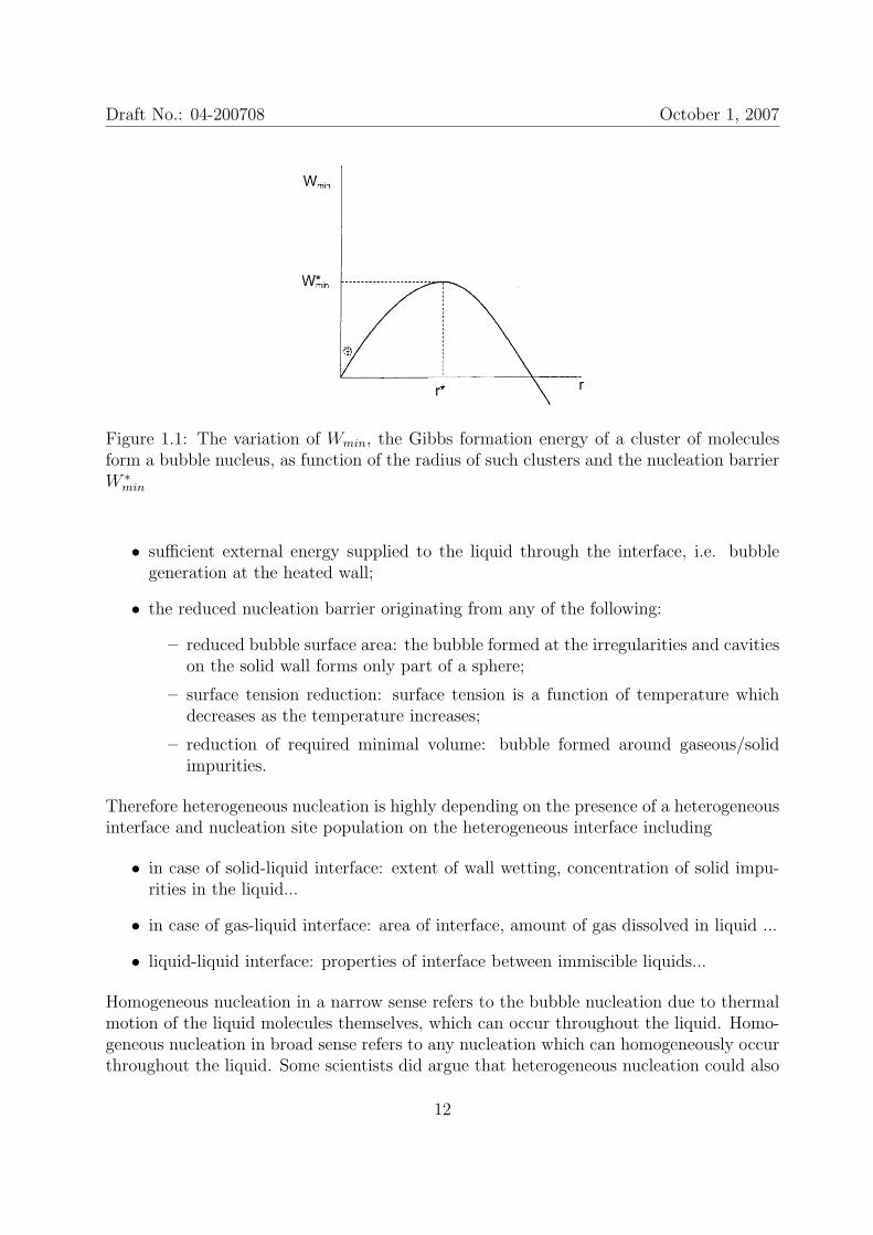
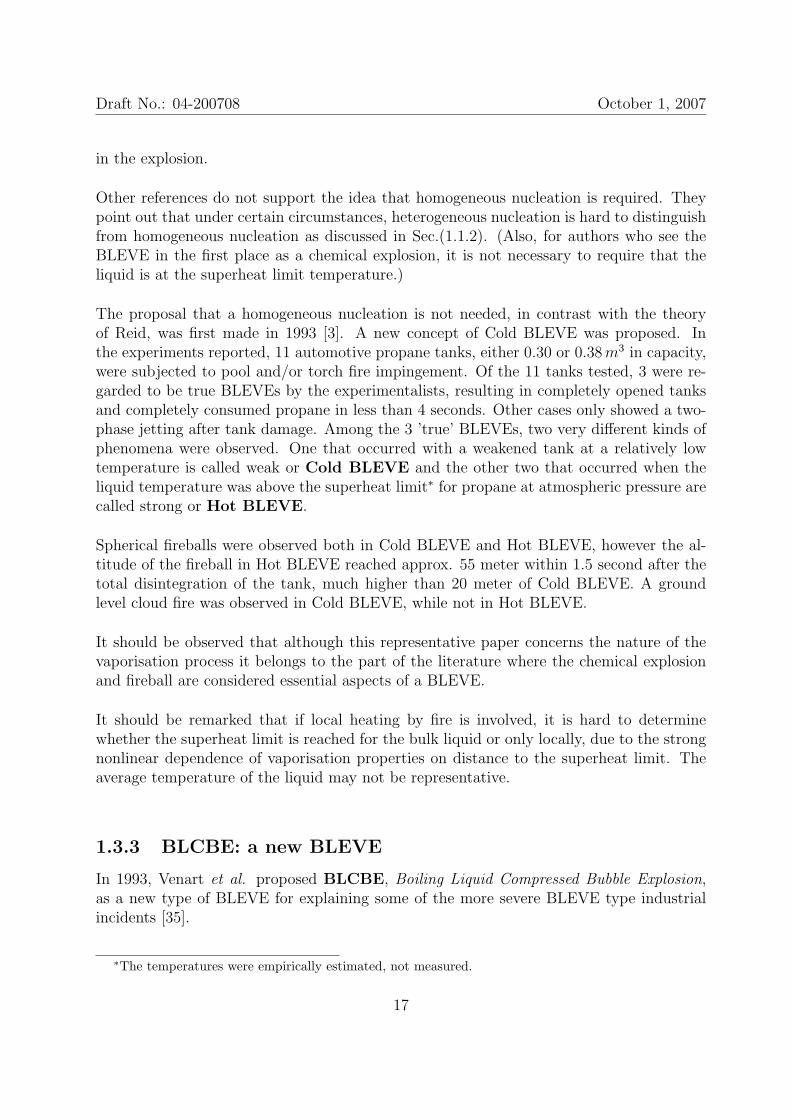
As shown in Fig.(1.1) from [7], W ∗min, the maximum of Wmin, works as the nucleation
barrier and corresponds to a critical bubble radius r∗. For nuclei smaller than r∗, moreenergy is needed for growing and for nuclei larger than r∗, less energy is required.
Heterogeneous nucleation and homogeneous nucleation are two different ways of bubblenuclei generation. Heterogeneous nucleation occurs at the interface of two phases. At thisinterface, the nucleation can benefit from
11
Draft No.: 04-200708 October 1, 2007
Figure 1.1: The variation of Wmin, the Gibbs formation energy of a cluster of moleculesform a bubble nucleus, as function of the radius of such clusters and the nucleation barrierW ∗
min
• sufficient external energy supplied to the liquid through the interface, i.e. bubblegeneration at the heated wall;
• the reduced nucleation barrier originating from any of the following:
– reduced bubble surface area: the bubble formed at the irregularities and cavitieson the solid wall forms only part of a sphere;
– surface tension reduction: surface tension is a function of temperature whichdecreases as the temperature increases;
– reduction of required minimal volume: bubble formed around gaseous/solidimpurities.
Therefore heterogeneous nucleation is highly depending on the presence of a heterogeneousinterface and nucleation site population on the heterogeneous interface including
• in case of solid-liquid interface: extent of wall wetting, concentration of solid impu-rities in the liquid...
• in case of gas-liquid interface: area of interface, amount of gas dissolved in liquid ...
• liquid-liquid interface: properties of interface between immiscible liquids...
Homogeneous nucleation in a narrow sense refers to the bubble nucleation due to thermalmotion of the liquid molecules themselves, which can occur throughout the liquid. Homo-geneous nucleation in broad sense refers to any nucleation which can homogeneously occurthroughout the liquid. Some scientists did argue that heterogeneous nucleation could also
12
Draft No.: 04-200708 October 1, 2007
occur on very small, sub-micron sized contaminant particles in the liquid; experimentallythis would be hard to distinguish from homogeneous nucleation (see Section 1.6 in [5]). Atpresent in this project, we use the concept of homogeneous nucleation in narrow sense.
The major difference between homogeneous nucleation and heterogeneous nucleation is thebubble/nuclei number density. It has been widely accepted that homogeneous nucleationcould generate bubble number density of 1010 - 1012m−3s−1 while in general heterogeneousnucleation has a much lower bubble number density.
Back to the energy discussion. If the conditions are favourable for formation of a hugenumber of nuclei and sufficiently energy is available for rapid further growth of nuclei tobubbles the vaporization process will be explosive and hazardous. Huge nucleus numberdensity and high energy supply will result in explosive boiling. So the violence of boil-ing/vaporisation depends on
1. Bubble nucleation rate
2. Energy transfer to the nuclei
Interaction between neighbouring bubbles, eventually will also have to be taken into ac-count.
1.2 BLEVE as a hazard
After having introduced some basic physical concepts, we now move on to the engineeringfield and see what superheated liquid, homogeneous nucleation and explosive boiling cando in real engineering problems.
1.2.1 BLEVE
Let’s start with one definition of BLEVE.
BLEVE, Boiling Liquid Expanding Vapor Explosion, is an explosion as the consequence ofthe catastrophic rupture of a pressure vessel containing a liquefied gas. The catastrophicrupture of the vessel will normally directly expose the liquefied gas to the ambient. Thesudden depressurization will lead to an explosive vaporization inside the bulk of the liq-uid. Blast wave and even shock wave can be generated to have destructive impact on thesurroundings and human bodies as well as the projectiles. If the liquid is flammable, jetfire, pool fire and fireball will cause fire hazard.
The vessel rupture can be due to mechanical impact, exposure to an external fire, fatigueof the vessel, corrosion and/or a bad construction or malfunctioning component. The di-rect hazards from a BLEVE normally include blast wave, projectiles, fire engulfment and
13
Draft No.: 04-200708 October 1, 2007
thermal radiation and/or exposure and health problems if the content is toxic.
1.2.2 Tunnel safety
This study is made in the context of a set of studies on the safety of road constructionsin the Netherlands, in particular tunnels. The increase in the number of tunnels in theNetherlands, and the increasing intensity of the traffic through these tunnels, requires goodinsight in the risks associated with this traffic. An important safety aspect is the risk forthe occurrence of a gas explosion in case of an accidental release of a flammable material,or a blast wave due to the failure of the pressure vessel of a truck carrying a liquid at highpressure (BLEVE).
For either case, the hazard depends on the rate at which the potential energy stored insidethe tank is released in the limited volume of space in the tunnel. An intense blast waveor shock wave can result and impose a high overpressure on the tunnel structure (as wellas on the vehicles and human bodies present in the tunnel. Therefore it is important tobe able to predict the strength of this blast wave as function of all relevant aspects (e.g.transported liquid, truck and tunnel type, incident scenario, etc.)
1.2.3 Causes for BLEVE
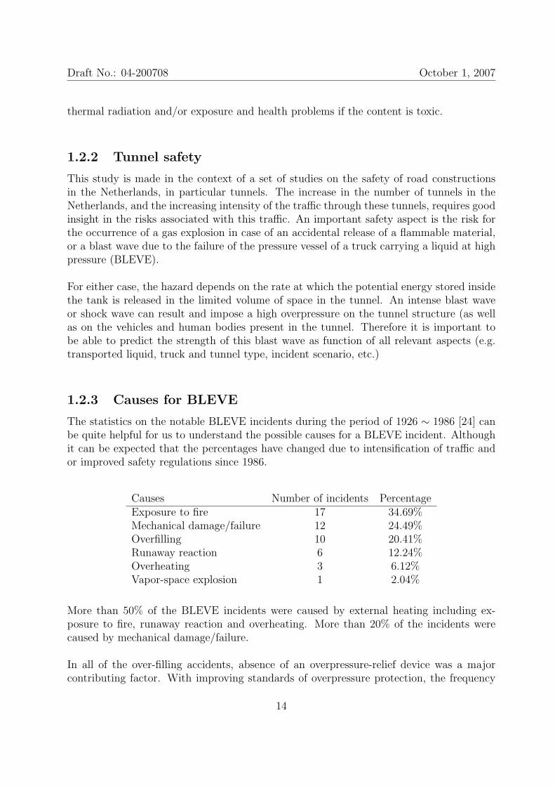
The statistics on the notable BLEVE incidents during the period of 1926 ∼ 1986 [24] canbe quite helpful for us to understand the possible causes for a BLEVE incident. Althoughit can be expected that the percentages have changed due to intensification of traffic andor improved safety regulations since 1986.
Causes Number of incidents PercentageExposure to fire 17 34.69%Mechanical damage/failure 12 24.49%Overfilling 10 20.41%Runaway reaction 6 12.24%Overheating 3 6.12%Vapor-space explosion 1 2.04%
More than 50% of the BLEVE incidents were caused by external heating including ex-posure to fire, runaway reaction and overheating. More than 20% of the incidents werecaused by mechanical damage/failure.
In all of the over-filling accidents, absence of an overpressure-relief device was a majorcontributing factor. With improving standards of overpressure protection, the frequency
14
Draft No.: 04-200708 October 1, 2007
of BLEVEs caused by overfilling could be expected to decline significantly. Moreover it isremarkable that the accidents caused by the over-filling often lead to high fatalities.
Incidents caused by vapor-space explosion and mechanical failure are the least frequentand their descriptions also indicated that they were very random and therefore hard topredict.
It is clear that external heating (EF) and mechanical damage (MI) are the most com-mon causes for BLEVE incidents. In this project, these two accidental modes will receivemost attention.
1.3 What are the key elements of a BLEVE ?
The term ’BLEVE’ was first introduced by J.B. Smith, W.S. Marsh and W.L. Walls offactory Mutual Research Corporation in 1957. When it was invented it was used to describea phenomenon rather than to give a clear definition. The five words stand as a block, butthe relation of the ’explosion’ to the ’expanding vapor’ of the ’boiling liquid’ is not obvious.And no further specification is given of the type of boiling. This has caused discrepancy ininterpretation of the acronym among scientists and the engineers. The discrepancy mainlyrefers to two points
• whether the explosion is limited to physical explosion or it can include chemicalreaction/explosion;
• whether the superheat limit must be reached or not in triggering a BLEVE.
It will shown below that the complicated scenarios possibly involved in BLEVEs bringdifficulty in defining a BLEVE.
1.3.1 BLEVE: physical or chemical
Many engineering references consider chemical explosion an essential part of a BLEVE.This is reasonable because most PLG, Pressure-Liquefied-Gas, stored in commercial tanksis flammable and external fire is a main reason for tank weakening and total disintegration.Under such circumstances, chemical reaction of the released liquid with the surroundingair, leading to explosion is almost certain to occur. On the other hand, chemical reactionis not a must for a BLEVE to occur even though it can make things much worse. Theexplosion can be a completely physical one caused by the rapid volume expansion dueto rapid vaporization. So there are two possibilities to logically interpret ’Boiling LiquidExpanding Vapor Explosion’:
15
Draft No.: 04-200708 October 1, 2007
• a physical explosion completely due to liquid boiling and vapor expansion;
• a chemical explosion of flammable liquid which has been intensified by liquid boilingand vapor expansion.
In the INERIS report 2002 [16], BLEVE is qualified as a physical explosion in the sensethat it corresponds to a phase change only, in contrast with a chemical explosion corre-sponding to an oxidation reaction.
But in the engineering literature, especially from the Process Industry, often a tank con-taining flammable PLG engulfed in an external fire is considered and the standard scenarioof a BLEVE also includes a chemical explosion. It goes as follows [19]: As the fire heats thetank, the fluid inside rises in temperature and pressure, roughly following the saturationcurve, although, temperature stratification may occur in the liquid and vapor. NormallyPRV, Pressure Relief Valve, action is introduced when the set pressure is reached. Thefluid is vented and may be ignited to form a torch if flammable. The pressure inside thetank is controlled around the set pressure of the PRV if it is still functioning correctly. If forsome reason the tank tears open, the fluid is exposed to atmospheric pressure. Thereforethe liquid becomes superheated and starts to boil rapidly and violently resulting a pressurerise inside the tank, which may speed up the rupture development until a catastrophic fail-ure of the tank and chemical explosion of the released fuel with the surrounding air. Thechemical potential is in general a more powerful explosion than the pure physical explosion,caused by the rapid boiling of the superheated liquid and the rapid vapor expansion.
The standard scenario of the Process Industry literature may not be the most relevant forstudies on Tunnel Safety. Mechanical impact, not external fire, can be expected to be themain cause of the failure of the pressure vessel. And the mixing with the surroundingscan be completely different in a tunnel geometry. Nevertheless, if external fire occurs,depending on its relative position to the pressure vessel, it can serve as an ignition pointto the flammable fluid, a heat source to PLG and/or a weakening factor to the strength ofthe pressure vessel.
1.3.2 BLEVE: hot and cold
If we now focus on aspects of the rapid vaporisation of a BLEVE, it appears that anotherdiscussion point remains on what is essential for a BLEVE. Is it required that the superheatlimit is reached or not ? In other words: is homogeneous nucleation essential or not ? Someauthors think it is because they believe that it explains why the vaporization is so violentand results in an explosion. The theory presented by R.C. Reid [25] [26] considers that aliquid at a temperature above the limit superheat temperature when it is depressurized toatmospheric pressure gives rise to a BLEVE. This definition has been widely accepted. Itexplains why both flammable and non-flammable liquids can show a large energy release
16
Draft No.: 04-200708 October 1, 2007
in the explosion.
Other references do not support the idea that homogeneous nucleation is required. Theypoint out that under certain circumstances, heterogeneous nucleation is hard to distinguishfrom homogeneous nucleation as discussed in Sec.(1.1.2). (Also, for authors who see theBLEVE in the first place as a chemical explosion, it is not necessary to require that theliquid is at the superheat limit temperature.)
The proposal that a homogeneous nucleation is not needed, in contrast with the theoryof Reid, was first made in 1993 [3]. A new concept of Cold BLEVE was proposed. Inthe experiments reported, 11 automotive propane tanks, either 0.30 or 0.38m3 in capacity,were subjected to pool and/or torch fire impingement. Of the 11 tanks tested, 3 were re-garded to be true BLEVEs by the experimentalists, resulting in completely opened tanksand completely consumed propane in less than 4 seconds. Other cases only showed a two-phase jetting after tank damage. Among the 3 ’true’ BLEVEs, two very different kinds ofphenomena were observed. One that occurred with a weakened tank at a relatively lowtemperature is called weak or Cold BLEVE and the other two that occurred when theliquid temperature was above the superheat limit∗ for propane at atmospheric pressure arecalled strong or Hot BLEVE.
Spherical fireballs were observed both in Cold BLEVE and Hot BLEVE, however the al-titude of the fireball in Hot BLEVE reached approx. 55 meter within 1.5 second after thetotal disintegration of the tank, much higher than 20 meter of Cold BLEVE. A groundlevel cloud fire was observed in Cold BLEVE, while not in Hot BLEVE.
It should be observed that although this representative paper concerns the nature of thevaporisation process it belongs to the part of the literature where the chemical explosionand fireball are considered essential aspects of a BLEVE.
It should be remarked that if local heating by fire is involved, it is hard to determinewhether the superheat limit is reached for the bulk liquid or only locally, due to the strongnonlinear dependence of vaporisation properties on distance to the superheat limit. Theaverage temperature of the liquid may not be representative.
1.3.3 BLCBE: a new BLEVE
In 1993, Venart et al. proposed BLCBE, Boiling Liquid Compressed Bubble Explosion,as a new type of BLEVE for explaining some of the more severe BLEVE type industrialincidents [35].
∗The temperatures were empirically estimated, not measured.
17
Draft No.: 04-200708 October 1, 2007
A BLCBE is described as a series of events including [36]:
1. partial vessel failure i.e. a crack;
2. rapid depressurization of an already nucleated and now superheated liquid;
3. rapid bubble growth and then constraint of the two-phase system (by either physical,acoustic, or inertial means);
4. repressurization back to nearly the original containment pressure;
5. adaptive and coherent bubble collapse resulting in the formation of power amplifiedliquid shock waves;
6. wall-pressure wave interaction resulting in total and rapid vessel destruction;
7. mechanical distribution of the liquid contents as an aerosol;
8. heat transfer and total evaporation (and if flammable auto-ignition) of the aerosol.
The key feature of BLCBE is the process of repressurization which compresses the growingbubbles. In this way energy is accumulated inside the bubbles and released simultaneouslywhen the tank totally disintegrates.
This is another way to demonstrate the complex in the possible scenario involved in aBLEVE which may result in explosive hazards, besides R.C. Reid’s superheat limit theory.
1.3.4 Conclusion: criteria for defining BLEVE
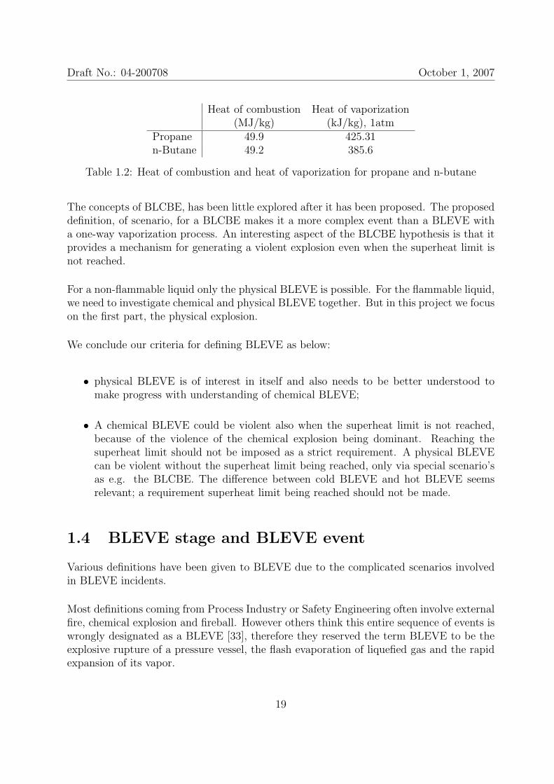
We need to distinguish chemical BLEVE from physical BLEVE, because these two explo-sions are different both in their nature and in their consequences. The driving force forphysical BLEVE is vaporization due to non-equilibrium between the liquid and gaseousphases. The driving force for chemical BLEVE is combustion, chemical reaction due tonon-equilibrium in vapour/gas space. The heat of vaporisation and heat of combustion(with air) are both liquid properties, but the heat of combustion is in general several or-ders larger than the heat of vaporization. We take the heat of combustion† and heat ofvaporization‡ of propane and n-butane for comparisontherefore if the volume expansion is favoured by a good mixing between the superheatedliquid and the air (vaporization extracts energy from the air) in both physical BLEVE andchemical BLEVE, the volume expansion in chemical BLEVE is further favoured by thereleased heat of combustion in a much powerful manner.
†data from Wiki, http : //en.wikipedia.org/wiki/Heat of combustion‡data from Air Liquide, http : //encyclopedia.airliquide.com
18
Draft No.: 04-200708 October 1, 2007
Heat of combustion Heat of vaporization(MJ/kg) (kJ/kg), 1atm
Propane 49.9 425.31n-Butane 49.2 385.6
Table 1.2: Heat of combustion and heat of vaporization for propane and n-butane
The concepts of BLCBE, has been little explored after it has been proposed. The proposeddefinition, of scenario, for a BLCBE makes it a more complex event than a BLEVE witha one-way vaporization process. An interesting aspect of the BLCBE hypothesis is that itprovides a mechanism for generating a violent explosion even when the superheat limit isnot reached.
For a non-flammable liquid only the physical BLEVE is possible. For the flammable liquid,we need to investigate chemical and physical BLEVE together. But in this project we focuson the first part, the physical explosion.
We conclude our criteria for defining BLEVE as below:
• physical BLEVE is of interest in itself and also needs to be better understood tomake progress with understanding of chemical BLEVE;
• A chemical BLEVE could be violent also when the superheat limit is not reached,because of the violence of the chemical explosion being dominant. Reaching thesuperheat limit should not be imposed as a strict requirement. A physical BLEVEcan be violent without the superheat limit being reached, only via special scenario’sas e.g. the BLCBE. The difference between cold BLEVE and hot BLEVE seemsrelevant; a requirement superheat limit being reached should not be made.
1.4 BLEVE stage and BLEVE event
Various definitions have been given to BLEVE due to the complicated scenarios involvedin BLEVE incidents.
Most definitions coming from Process Industry or Safety Engineering often involve externalfire, chemical explosion and fireball. However others think this entire sequence of events iswrongly designated as a BLEVE [33], therefore they reserved the term BLEVE to be theexplosive rupture of a pressure vessel, the flash evaporation of liquefied gas and the rapidexpansion of its vapor.
19
Draft No.: 04-200708 October 1, 2007
1.4.1 Definitions
In our study, we clearly distinguish two concepts, BLEVE and BLEVE event, as Pinhasiet al. did in [21].
BLEVE event is defined to be an event in which a tank containing PLG is suffered me-chanical impact and/or external fire and later totally disintegrated.
BLEVE is just the physical expansion (explosion) stage of a BLEVE event.
There are only two requirements for a BLEVE event, as the description of ’an explodingpressure vessel of liquefied gas’ in [33], (i) PLG in a certain confinement; (ii) Sudden TotalLoss of the Confinement (TLOC). Therefore, a BLEVE event can involve chemical explo-sion and fireball as well, but BLEVE must not.
1.4.2 Three stages of a BLEVE event
A BLEVE event can be divided into three stages with two time frames: (i) the moment ofTLOC; (ii) the moment of chemical reaction commences.
Pre-BLEVE stage The process from the initiation of the accident to the moment ofTLOC;
BLEVE stage The process from the moment of TLOC to any chemical reaction or chem-ical explosion commences;
Post-BLEVE stage The process involving chemical reaction or chemical explosion.
By strictly distinguishing BLEVE from BLEVE event, we can successfully explain twoso-called ’new BLEVE’, Cold BLEVE and BLCBE. Cold BLEVE is a BLEVE event inwhich the physical expansion in BLEVE stage only employs moderate or weak reinforce-ment to the chemical explosion in post-BLEVE stage. BLCBE is a BLEVE event with anenergy-accumulated pre-BLEVE stage which result in a more violent physical explosion inBLEVE stage.
1.4.3 Features of three stages
In general, the main feature of pre-BLEVE stage is variety. The features of BLEVE stageare rapidness. The main feature of post-BLEVE stage is chemical reaction.
Pre-BLEVE stage in MI includes
20
Draft No.: 04-200708 October 1, 2007
• Fluid-structure coupling, crack development coupled with the thermodynamic prop-erties of PLG
• Single or two-phase PLG release through the crack
• Vaporization of the released liquid and expansion of the vapor outside the vessel
Pre-BLEVE stage in EF includes:
• Thermal response of the vessel wall and PLG to the external fire
• Crack initiation and its development
• Combustion of the released vapor/liquid in the formation of pool fire or torch
BLEVE stage includes:
• Rapid exposure of the pressurized vapor and liquid to the ambient
• Projection of the vapor and liquid due to pressure difference
• Rapid vaporization and expansion of PLG
• Gasdynamics of the surrounding air
Post-BLEVE stage, if there exists, includes:
• Chemical reaction/explosion
• Deflagration-to-Detonation Transition along the tunnel
1.5 Summary
In this chapter, the description of BLEVE and its hazards to tunnel safety have been gen-erally discussed. The difficulty lies in how to define a BLEVE which can possibly occur incompletely different scenarios and how to bridge the gaps among current existing defini-tions.
BLEVE and BLEVE event, two different concepts have been proposed. The purpose isto define the very basic and essential features of a BLEVE and exclude all the otherunnecessary ones although some are high correlated. We expect, by doing that, the defini-tion of BLEVE would become unique and clear at least within the project of Tunnel Safety.
The BLEVE event is further divided into three stages, pre-BLEVE, BLEVE and post-BLEVE, by two time frames. It will be shown in the following chapters that the theory,the mechanism, the governing equations and the numerical models for different stages are
21
Draft No.: 04-200708 October 1, 2007
greatly different. Different stages have different problems to solve.
The statistics on BLEVE accidents indicated that external heating and mechanical damageare the main causes for BLEVE accidents. Two specific accidental mode, external fire andmechanical impact, will be mainly focused on in the project of Tunnel Safety.
22
Chapter 2
Theories of Bubble vaporization
In this chapter, we will give an overview of the theoretical approaches of bubble vaporiza-tion. It will be shown that as the liquid superheat increases, the physics for the bubblenucleation and vaporization will change. The classical theories can not properly describethe bubble nucleation and growth at high superheats, especially in the initial phase. Effortshas been made either for upgrading the classical theories or for developing new methodsfor bubble vaporization research.
The references in this chapter include: [5], [7], [18], [23], [30] and [31].
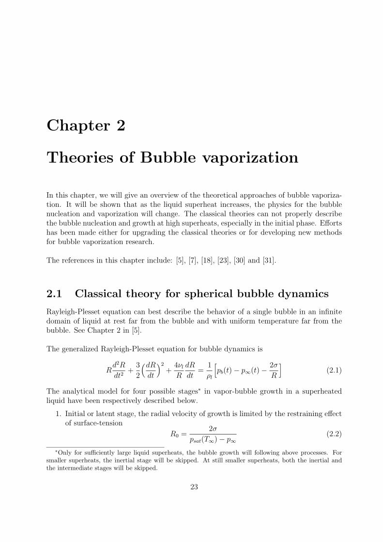
2.1 Classical theory for spherical bubble dynamics
Rayleigh-Plesset equation can best describe the behavior of a single bubble in an infinitedomain of liquid at rest far from the bubble and with uniform temperature far from thebubble. See Chapter 2 in [5].
The generalized Rayleigh-Plesset equation for bubble dynamics is
Rd2R
dt2+
3
2
(dRdt
)2
+4νl
R
dR
dt=
1
ρl
[pb(t)− p∞(t)− 2σ
R
](2.1)
The analytical model for four possible stages∗ in vapor-bubble growth in a superheatedliquid have been respectively described below.
1. Initial or latent stage, the radial velocity of growth is limited by the restraining effectof surface-tension
R0 =2σ
psat(T∞)− p∞(2.2)
∗Only for sufficiently large liquid superheats, the bubble growth will following above processes. Forsmaller superheats, the inertial stage will be skipped. At still smaller superheats, both the inertial andthe intermediate stages will be skipped.
23
Draft No.: 04-200708 October 1, 2007
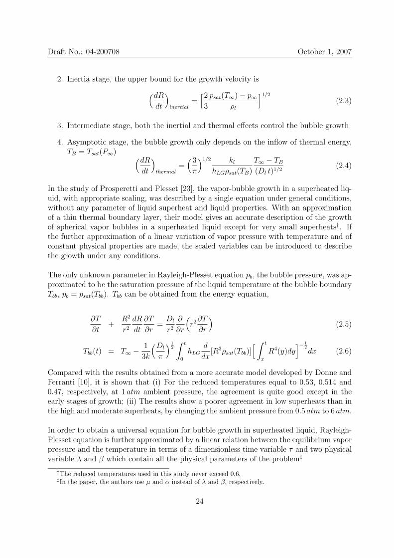
2. Inertia stage, the upper bound for the growth velocity is
(dRdt
)inertial
=[2
3
psat(T∞)− p∞ρl
]1/2
(2.3)
3. Intermediate stage, both the inertial and thermal effects control the bubble growth
4. Asymptotic stage, the bubble growth only depends on the inflow of thermal energy,TB = Tsat(P∞) (dR
dt
)thermal
=( 3
π
)1/2 kl
hLGρsat(TB)
T∞ − TB
(Dl t)1/2(2.4)
In the study of Prosperetti and Plesset [23], the vapor-bubble growth in a superheated liq-uid, with appropriate scaling, was described by a single equation under general conditions,without any parameter of liquid superheat and liquid properties. With an approximationof a thin thermal boundary layer, their model gives an accurate description of the growthof spherical vapor bubbles in a superheated liquid except for very small superheats†. Ifthe further approximation of a linear variation of vapor pressure with temperature and ofconstant physical properties are made, the scaled variables can be introduced to describethe growth under any conditions.
The only unknown parameter in Rayleigh-Plesset equation pb, the bubble pressure, was ap-proximated to be the saturation pressure of the liquid temperature at the bubble boundaryTbb, pb = psat(Tbb). Tbb can be obtained from the energy equation,
∂T
∂t+
R2
r2
dR
dt
∂T
∂r=Dl
r2
∂
∂r
(r2∂T
∂r
)(2.5)
Tbb(t) = T∞ − 1
3k
(Dl
π
) 12
∫ t
0
hLGd
dx[R3ρsat(Tbb)]
[ ∫ t
x
R4(y)dy]− 1
2dx (2.6)
Compared with the results obtained from a more accurate model developed by Donne andFerranti [10], it is shown that (i) For the reduced temperatures equal to 0.53, 0.514 and0.47, respectively, at 1 atm ambient pressure, the agreement is quite good except in theearly stages of growth; (ii) The results show a poorer agreement in low superheats than inthe high and moderate superheats, by changing the ambient pressure from 0.5 atm to 6 atm.
In order to obtain a universal equation for bubble growth in superheated liquid, Rayleigh-Plesset equation is further approximated by a linear relation between the equilibrium vaporpressure and the temperature in terms of a dimensionless time variable τ and two physicalvariable λ and β which contain all the physical parameters of the problem‡
†The reduced temperatures used in this study never exceed 0.6.‡In the paper, the authors use µ and α instead of λ and β, respectively.
24
Draft No.: 04-200708 October 1, 2007
V43
[Vd2V
dτ 2+
7
6
(dVdτ
)2]= 3
[1− λ
∫ τ
0
(τ − θ)−12dV
dθ− V − 1
3
](2.7)
with the initial condition of V (0) = 1 and may further become
y43
[yd2y
dx2+
7
6
(dydx
)2]= 3
[1−
∫ x
0
(x− ξ)−12dy
dξdξ − λ2y−
13
](2.8)
with the initial condition of y(0) = λ6. If two physical variables R and t are defined to be
R = λ2R/R0 = y13 , (2.9)
t = βλ2t =
∫ x
0
y−43 (ξ)dξ (2.10)
The relation R = R(t) is independent of the physical parameters β and λ except in theinitial stages of the growth. The asymptotic relations (2.3) and (2.4) become
(dRdt
)inertial
=(2
3
) 12,
(dRdt
)thermal
= π−1(3t)−12 (2.11)
The results are compared with Donne & Ferranti’s again and it is shown that
• The physical variables λ and β do include in a physically meaningful way all thequantities relevant for the growth of vapor bubbles in superheated liquid under avery wide range of conditions.
• The times required for growth to the indicated value of R/R0 are shown as a functionof λ.
• The differences in initial stages still present.
• The scaled growth rate for very large superheat§ are seen to deviate considerably andthese discrepancies have limited effects on the R(t) results.
For the study of Prosperetti and Plesset [23], it should be noted that
• This scaled description is valid only for bubbles that have grown by about an orderof magnitude beyond their initial radius, so that surface-tension effects have becomeunimportant. This limitation is inconsequential in practice, particularly for moderateand large liquid superheats.
• The asymptotic stage of bubble growth was accurately described by the scaled for-mulation. However the rate of bubble growth for large superheats is overestimatedin the intermediate stage.
• This classical theory of bubble growth does not describe explosive boiling (see [30]).
§In the case of high superheat it may be possible to evaluate the physical properties appearing in βand λ at a temperature different from TB
25
Draft No.: 04-200708 October 1, 2007
2.2 Homogeneous nucleation theory
The modern homogeneous nucleation has been investigated in detail both experimentallyand theoretically by Volmer & Weber [37], J. Frenkel [12], V.P. Skripov [32], Blander andKatz [4], and others.
The classical homogeneous nucleation theory estimates the energy barrier to nucleation bytreating the droplet or the bubble as composed of a bulk core surrounded by an interface.If a very small bubble is formed within a large homogeneous mass, we can consider thatthis does not change the state of the matter in the outer phase. In this case, independentlyof the type of constants imposed on the simple system (for example, T, p = constant ors, v = constant), the minimum work of formation of the bubble is described by the sameequation
Wmin = σA− (pv − pl)V + i(µv − µl) (2.12)
where A is the surface area of the bubble, pv is the vapor pressure within the bubble, pl isthe surrounding liquid pressure, V is the volume of the bubble, i is the number of moleculesinside the bubble and µv and µl are, respectively, the chemical potentials of the vapor andliquid phases. For a spherical vapor bubble (or a spherical ’cluster’ of vapor molecules) ofradius r, Eqn.(2.12) reads
Wmin = 4πr2σ − 4
3πr3(pv − pl) + i(µv − µl) (2.13)
The first term represents the work of surface formation, the second term the volume workdirected against the pressure forces, and the third the ’molecular’ work. It is well-knownthat the minimum work Wmin exhibits a maximum W ∗
min at the critical bubble radius r∗
given by
(∂Wmin
∂r
)r=r∗
= 0 and(∂2Wmin
∂r2
)r=r∗
< 0 (2.14)
Suppose the critical bubble is in mechanical and chemical equilibrium¶, Eqn.(2.13) can bewritten in a simpler form as a function of the radius of the critical bubble r∗
W ∗min =
1
3σA∗ =
1
2V ∗(pv − pl), A∗ = 4πr∗2, V ∗ =
4
3πr∗3 (2.15)
or
W ∗min =
16πσ3
3(pv − pl)2(2.16)
or in reduced units
¶It implies that pv = pl + 2σr and µv(pv, T ) = µl(pl, T ), however mechanical equilibrium may not
necessarily hold at r = r∗ [7]
26
Draft No.: 04-200708 October 1, 2007
W ∗min
kBT=
4
27
[σA∗/(kBT )]3
[(pv − pl)V ∗/(kBT )]2(2.17)
The final step in homogeneous nucleation theory is an evaluation of the mechanism by whichenergy deposition could occur and the probability of that energy reaching the magnitude,W ∗
min, in the available time [5]. In the body of a pure liquid completely isolated fromany external radiation, this issue is reduced to an evaluation of the probability that thestochastic nature of the thermal motions of the molecules would lead to a local energyperturbation of magnitude W ∗
min. Most of the homogeneous nucleation theories thereforerelate W ∗
min to the typical kinetic energy of the molecules, namely kBT and the relationshipis couched in terms of a Gibbs number,
Gb =W ∗
min
kBT(2.18)
A number of experssions have been proposed for the precise form of the relationship betweenthe nucleation rate, J , defined as the number of nucleation events occuring in a unit volumeper unit time and the Gibbs number, Gb, but all take the general form
J = J0 e−Gb (2.19)
where J0 is some factor of proportionality. Various functional forms have been suggestedfor J0. A typical form is that given by Blander and Katz [4], namely
J0 = N( 2σ
πmm
)(2.20)
where N is the number of molecules per unit volume for the liquid and mm is the mass ofa molecule. Though J0 may be a function of temperature, the effect of an error in J0 issmall compared with the effect on the exponent, Gb, in Eqn.(2.19).
2.2.1 Extended homogeneous nucleation theory
Despite its success in predicting the superheat limit of liquids assuming the nucleationrates about J = 1010 ∼ 1012m−3s−1, the classical homogeneous nucleation theory has beenwidely criticized for
• ignoring the effect of curvature on surface free energy;
• predicting a finite barrier when the spinodal is approaching;
• its failure to predict the tensile strength of liquid at relatively low temperatures;
• providing low steady-state nucleation rates
27
Draft No.: 04-200708 October 1, 2007
Extensions of the classical theory are also criticized for as either being thermodynamicallyinconsistent or not satisfying the nucleation theorem.
In the study of Delale et al. [7], the classical homogeneous nucleation was reconsideredby employing a new phenomenological nucleation barrier in the capillarity approximationthat utilizes the superheat threshold achieved in experiments. An algorithm to calculatethe superheat limit temperature, critical bubble radius and steady-state nucleation ratehas been developed.
By adding a non-negative phenomenological correction term, F ∗(T, pl) > 0, to the freeenergy for the formation of a vapor bubble of critical size r∗, Eqn.(2.13) for the minimumwork of formation for mechanical equilibrium at r = r∗ becomes
W ∗min = 4 π r∗2 σ − 4
3π r∗3 (p∗v − pl)exp − F ∗(T, pl) (2.21)
The equation to be solved for the superheat limit temperature TSL for a given liquidpressure pl is
pl
pc
=pv,∞pc
1− κ
η
(1− TSL/Tc)ε
TSL/Tc
[ hLG
RTc(Zv − Zl)
](1− Zl
Zv
)(2.22)
where R is the specific gas constant; hLG is the latent heat of vaporization at TSL; κ isa substance dependence constant obtained by fitting the experimentally measured TSL at1 atm into above equation. η is given by the relation
η = 1− ρv,∞ρl
+1
2
(ρv,∞ρl
)2
and the exponent ε, standing for the power law temperature dependence of the expansionwork (p∗v − pl)expV
∗, is estimated to be the same for all substances, ≈ 2.2 as confirmed inexperiments.
The phenomenological correction F ∗(TSL, pl)‖ is regarded as a function of TSL and approx-
imated by a fraction θ of (p∗v − pl)expV∗ as
F ∗(TSL, pl) = θ(p∗v − pl)expV∗ =
8
3πθ r∗2σ (2.23)
Therefore by extrapolation from Tc down to the superheat temperatures, the steady-statenucleation rate becomes
J = Zv
( 3σρ2l
πm3m
)1/2
exp[− 4πr∗2σ
3kBTSL
(1− 2θ)]
(2.24)
With the two adjustable parameters κ and θ, an excellent agreement is observed betweenmeasured and predicted values of the superheat limit temperatures, which are shown to lie
‖F ∗(T, pl) is now evaluated at the superheat limit temperature TSL by extrapolation from Tc.
28
Draft No.: 04-200708 October 1, 2007
between the spinodals of the Berthelot and van de Waals equations of state. The nucle-ation rates were enhanced of 11 to 20 orders of magnitude over the one predicted by theclassical theory based on Eqn.(2.12).
2.2.2 Non-classical method on homogeneous nucleation
The classical nucleation theory breaks down near a spinodal (where the critical nucleus issmall in amplitude but large in spatial extent) or under conditions where the critical clus-ters of the new phases are small enough that the curvature of the cluster surface affects itsfree energy. In recent years, homogeneous nucleation is being investigated by nonclassicalmethods using the density functional methods or molecular dynamics simulations.
Density functional techniques of statistical mechanics have proven to be powerful ap-proaches to studying nonclassical nucleation of the gas-to-liquid transition and the reverseprocess of cavitation in expanded liquids. Effects arising from the proximity of spinodalsand from surface curvature are built into the density functional approaches used, and de-viation from the capillarity approximation (which lies at the heart of classical nucleationtheory) can be studied.
In 1998, M. Matsumuto reviewed the studies on microscopic mechanism of phase changefor various fluid systems using molecular dynamics simulation [18]. The dynamic behaviorof molecules near the surface has been classified into four catagories, evaporation, self-reflection, condensation and molecular exchange. The fourth type, molecular exchange,becomes quite important for some cases such as associating fluids and fluids at high tem-peratures.
Moreover when the liquid and vapor is in equilibrium, the condensation coefficient αc isfound to be strongly dependent on the temperature due to the molecular exchange sincesuch a behavior does not contribute to the condensation flux.
The condensation and evaporation behavior is much complicated in the case of non-equilibrium conditions. The condensation behavior seems strongly dependent on the tem-perature and the density of vapor and when hot vapor condensation on cool liquid occurs,the general tendency of αc is
∂αc
∂Tv
> 0,∂αc
∂ρv
< 0
29
Draft No.: 04-200708 October 1, 2007
2.3 Kinetic theory analysis of explosive boiling of a
superheated droplet
Modern understanding of the kinetics of evaporation from the interface surface can besummarized as follows: for a given temperature Tl of liquid phase, and for a correspondingvapor saturation pressure psat(Tl), the process depends on one additional free parameter,the ratio psat(Tl)/p∞, where p∞ is the external pressure. Other macroscopic quantities, liketemperature, velocity and mass flux, are found to be unique functions of this one param-eter. In the case of high reduced temperature (low evaporation coefficient), the pressureratio has little effect on the evaporation rate unless the ratio is very close to unity. Hence,the changes of vapor pressure inside the bubble have little influence on the evaporationrate. On the other hand, the pressure inside the bubble is influenced by the evaporationrate through hydrodynamics of the radial flow in the liquid phase. Therefore, when theevaporation rate saturates, both bubble growth rate and bubble pressure remain constant.See [31].
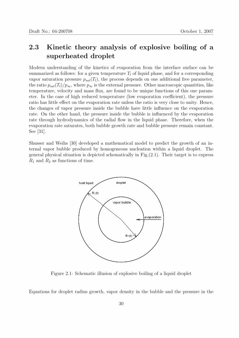
Shusser and Weihs [30] developed a mathematical model to predict the growth of an in-ternal vapor bubble produced by homogeneous nucleation within a liquid droplet. Thegeneral physical situation is depicted schematically in Fig.(2.1). Their target is to expressR1 and R2 as functions of time.
Figure 2.1: Schematic illusion of explosive boiling of a liquid droplet
Equations for droplet radius growth, vapor density in the bubble and the pressure in the
30
Draft No.: 04-200708 October 1, 2007
bubble are established from conservation equations. Several assumptions have been madebased on the previous experimental observations.
1. The vapor is an ideal gas.
2. Both the droplet liquid and the host liquid are invisid and incompressible.
3. The pressure within the vapor bubble is uniform (but can change in time).
4. The flow, bubble and droplet are radially symmetric and the bubble is formed at thecenter of the droplet∗∗.
Furthermore, the most important assumption for their model is that the evaporation rateis constant and equal to its maximal possible value, which is the kinetic theory limit tothe mass flux that can be attained in a phase-change process. This evaporation rate Je isgiven by the Hertz-Knudsen formula
Je = psat(TB)
√mM
2πRTB y(2.25)
where TB is the boiling temperature for the droplet liquid; psat(TB) is the saturation pres-sure at TB; R is the universal gas constant.
Applying above assumptions to the mass and momentum conservation equations, the equa-tions for droplet radius growth R2, vapor density in the bubble ρv and the pressure in thebubble pi are established respectively.
R2 =(R1 − Je
ρ
)R21
R22
(2.26)
ρv =Je
R1
(2.27)
pi = ρvRmM
TB (2.28)
Finally the approximate formula for bubble radius growth is given
R1 = b0
(2
3
Je
ρhl
RmM
TB
)1/3
(2.29)
where ρhl is the density of the host liquid and b0, an emperical coefficient, is estimated tobe 1.
∗∗In the appendix, the assumption of concentricity was inspected and it shows that the error in pressurewill be within 10% if the deviation of the bubble center from the droplet center is less than 25% of thedroplet radius.
31
Draft No.: 04-200708 October 1, 2007
Within 100µs, the calculated bubble radius growth agrees with the experimental results in[? ] quite well with a little overestimation but still much better than the model developedby Shepherd and Sturtevant in [? ] and the rate estimated from classical inertial growth.It is found by calculation that the bubble pressure can not drop if the host liquid has agreater density than the droplet liquid and vice versa. Shusser and Weihs conclude thatthe process of explosive boiling is characterized by bubble formation by homogeneous nu-cleation and evaporation rate that is equal to its kinetic theory limit.
‡
In the follower paper of Shusser et. al [31], their 1999 model has been justified. Shusserand Weihs 1999 model used an approximate algebraic relationship for vapor pressure insidethe bubble pi. The full form was retained to check the accuracy their approximation inthis study.
After comparison the results with the experimental data in [29], the best agreement wasobtained for the evaporation coefficient of 0.06 corresponding to a reduced temperature0.88 for butane. This very low value is also in agreement with the results of moleculardynamics simulations [18].
The time dependence of the evaporation rate Je was calculated. The error in the Shusserand Weihs 1999 model does not exceed 5.5% for the whole duration of the process andremains below 1% after 30µs. The approximated vapor pressure inside the bubble pi inShusser and Weihs 1999 model has been justified as well since the error is significant onlyduring very short period of the initial growth of the evaporation rate, in nanosecond.
Besides the high dependence of the pressure inside the bubble on the evaporation ratewhen the latter is low, low evaporation rate also influences the thermodynamic state of thevapor. It is shown that the vapor is highly superheated for aw = 0.06 and the temperatureof the vapor is about 98% of the temperature of the superheated liquid, i.e. by far largerthan the saturated vapor temperature.
There is about 10% difference in the bubble pressure computed from Shusser and Weihs1999 model and from this paper.
2.4 Summary
In this chapter, we have introduced several representative theoretical approaches relevantto the bubble vaporization.
32
Draft No.: 04-200708 October 1, 2007
The classical theory of bubble vaporization mainly focuses on describing the behavior ofbubble growth in slightly superheated liquid. In such a case, the liquid superheat couldnot overcome the energy barrier for critical bubbles therefore the bubble nuclei can onlyform on the sites where either the energy barrier is reduced or extra energy is fed to theliquid. The bubble growth is proceeding in a time frame that thermodynamic equilibriumbetween the liquid and vapor at the bubble surface is obtainable. A precise description ofthe bubble growth based on thermodynamic equilibrium can be established.
As the liquid is superheated further, due to density fluctuation, the energy barrier canbe overcome by liquid particles themselves besides the two possibilities mentioned above.The classical homogeneous nucleation theory is trying to explain how the bubble nuclei isinitiated at high superheats in two aspects: i) how much is the energy barrier? ii) howmuch is the bubble nucleation rate? However it has been shown that classical homoge-neous nucleation theory has been widely criticized for describing the initial phase of bubblenucleation. Some efforts has been made trying to extend the validity of the classical ho-mogeneous nucleation.
In recent decades, other methods have been developed to research bubble nucleation atextremely high superheat, i.e. molecular dynamic simulation and the kinetic model de-veloped by Shusser, Ytrehus and Weihs. These methods have succeeded in modelling thehomogeneous nucleation for a very small amount of liquid molecules. However for a reallarge-scale BLEVE problem, the molecular dynamic simulation is too expensive for mod-elling tons of liquid and the kinetic model is not sufficient as the length scale of the liquidincreases, from the diameter of one single droplet to the diameter of a large tank.
33
Chapter 3
The BLEVE event
In this chapter, we will discuss the whole BLEVE event trying to reveal the latest researchon each stage and the unsolved problems open to our study.
The characteristic feature of pre-BLEVE is ’variety and uncertainty’. The characteristicfeature of BLEVE stage is ’rapidness’. The characteristic feature of post-BLEVE stage is’chemical explosion’.
The reference in this chapter include: [1], [2], [6], [8], [9], [11], [15], [19], [21], [22], [25],[26], [27], [28], [29], [33] and [34].
3.1 Pre-BLEVE stage
The pre-BLEVE stage is the first stage of a BLEVE event. What we concern in this stageincludes
• How does a crack appear and propagate along the tank?
• Will the tank totally disintegrate? If yes, when and how will it be?
• What is the state of the PLG and the ambient when the tank totally disintegrates?
All these information is essential as the initial conditions for the BLEVE stage. Howeverthe variety and uncertainty in pre-BLEVE stage brings great difficulties to provide defini-tive initial conditions for the BLEVE stage.
34
Draft No.: 04-200708 October 1, 2007
3.1.1 Crack development
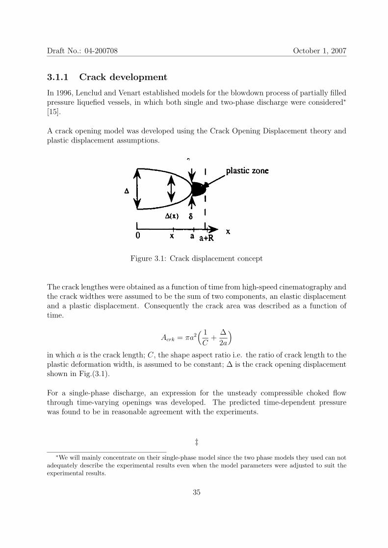
In 1996, Lenclud and Venart established models for the blowdown process of partially filledpressure liquefied vessels, in which both single and two-phase discharge were considered∗
[15].
A crack opening model was developed using the Crack Opening Displacement theory andplastic displacement assumptions.
Figure 3.1: Crack displacement concept
The crack lengthes were obtained as a function of time from high-speed cinematography andthe crack widthes were assumed to be the sum of two components, an elastic displacementand a plastic displacement. Consequently the crack area was described as a function oftime.
Acrk = πa2( 1
C+
∆
2a
)
in which a is the crack length; C, the shape aspect ratio i.e. the ratio of crack length to theplastic deformation width, is assumed to be constant; ∆ is the crack opening displacementshown in Fig.(3.1).
For a single-phase discharge, an expression for the unsteady compressible choked flowthrough time-varying openings was developed. The predicted time-dependent pressurewas found to be in reasonable agreement with the experiments.
‡∗We will mainly concentrate on their single-phase model since the two phase models they used can not
adequately describe the experimental results even when the model parameters were adjusted to suit theexperimental results.
35
Draft No.: 04-200708 October 1, 2007
The research on crack development is also carried out in another working package L-1 ofthe project Tunnel Safety by numerical methods.
We expect the output of working package L-1 will include
• Moment of the tank total disintegration as a function of tank material, liquid initialstate, initial crack area/shape/location or external fire intensity;
• Crack area as a function of time.
At present, the working package L-1 only uses a constant tank pressure for their crackdevelopment prediction. It will be shown later that the pressure in the tank oscillates withtime in a crazy manner, therefore it can be expected that the real tank total disintegrationwill happen ahead of the current prediction of working package L-1.
3.1.2 Vessel over-pressure
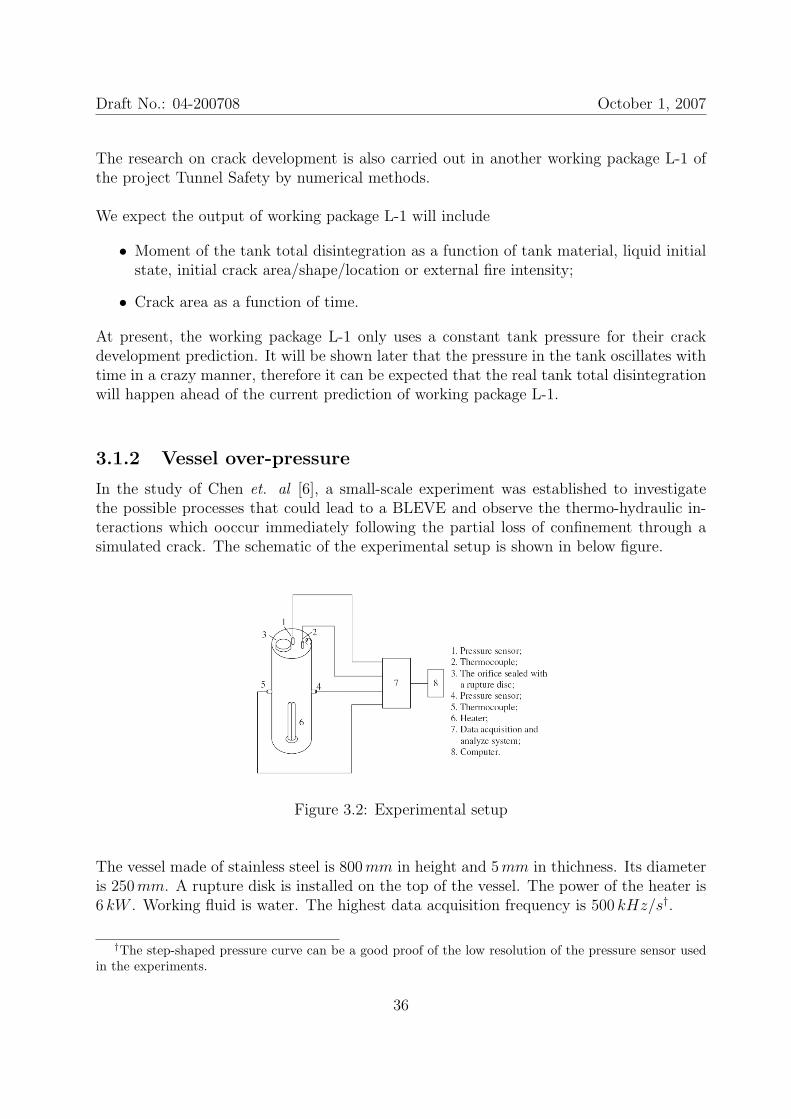
In the study of Chen et. al [6], a small-scale experiment was established to investigatethe possible processes that could lead to a BLEVE and observe the thermo-hydraulic in-teractions which ooccur immediately following the partial loss of confinement through asimulated crack. The schematic of the experimental setup is shown in below figure.
Figure 3.2: Experimental setup
The vessel made of stainless steel is 800mm in height and 5mm in thichness. Its diameteris 250mm. A rupture disk is installed on the top of the vessel. The power of the heater is6 kW . Working fluid is water. The highest data acquisition frequency is 500 kHz/s†.
†The step-shaped pressure curve can be a good proof of the low resolution of the pressure sensor usedin the experiments.
36
Draft No.: 04-200708 October 1, 2007
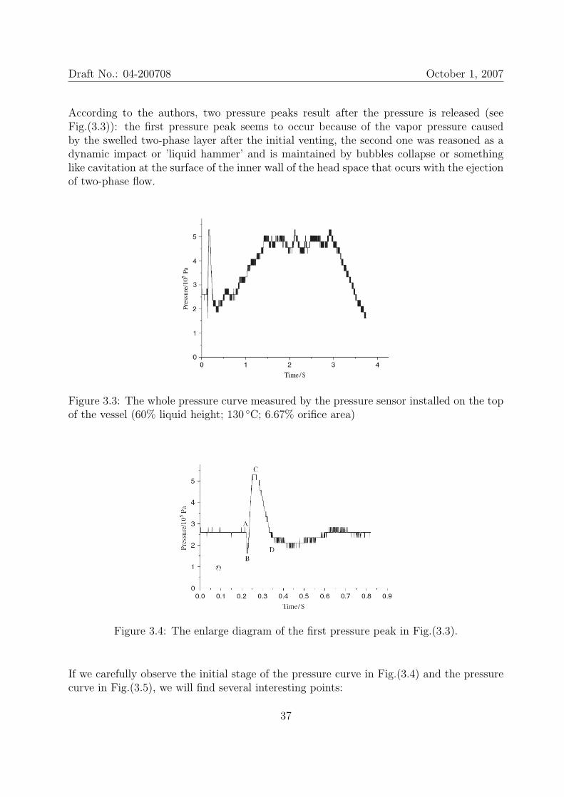
According to the authors, two pressure peaks result after the pressure is released (seeFig.(3.3)): the first pressure peak seems to occur because of the vapor pressure causedby the swelled two-phase layer after the initial venting, the second one was reasoned as adynamic impact or ’liquid hammer’ and is maintained by bubbles collapse or somethinglike cavitation at the surface of the inner wall of the head space that ocurs with the ejectionof two-phase flow.
Figure 3.3: The whole pressure curve measured by the pressure sensor installed on the topof the vessel (60% liquid height; 130 C; 6.67% orifice area)
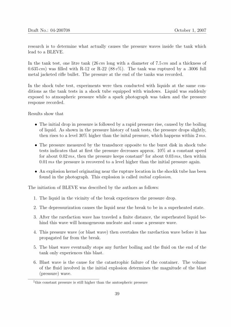
Figure 3.4: The enlarge diagram of the first pressure peak in Fig.(3.3).
If we carefully observe the initial stage of the pressure curve in Fig.(3.4) and the pressurecurve in Fig.(3.5), we will find several interesting points:
37

Draft No.: 04-200708 October 1, 2007
Figure 3.5: The whole pressure curve measured by the pressure sensor installed in the wallof the vessel at middle height (60% liquid height; 130 C; 6.67% orifice area)
• The initial high pressure is maintained for more than 200ms after the rupture diskis broken;
• Suddenly a pressure drop occurs throughout the tank as observed in the pressurecurves of the top and middle sensors. So far we don’t know the reason for this rapidpressure drop;
• The sudden pressure drop is immediately followed by a rapid repressurization, possi-bily because of the massive bubble nucleation/growth or the dynamic impact of thelading on the sensor;
• Before the first peak is finished, all the lading in the tank behaves roughly the sameat least in pressure aspect, their positions do not matter too much.
• After the pressure field is established, the pressure near the crack has the highestvalue and is maintained for nearly 1.5 s even after the pressure at the middle heightalready start to decrease.
The authors also carried out some research on the light height, orifice size and the degreeof liquid superheating. The results indicate that they all have different influence on themagnitue of the measured over-pressure. No empirical equation has been derived.
‡
In the study of McDevitt et. al [19], two sets of experiments have been performed to studythe initiation of a BLEVE: (i) Tank test and (ii) Shock tube test. The target of their
38
Draft No.: 04-200708 October 1, 2007
research is to determine what actually causes the pressure waves inside the tank whichlead to a BLEVE.
In the tank test, one litre tank (26 cm long with a diameter of 7.5 cm and a thickness of0.635 cm) was filled with R-12 or R-22 (88 v%). The tank was ruptured by a .3006 fullmetal jacketed rifle bullet. The pressure at the end of the tanks was recorded.
In the shock tube test, experiments were then conducted with liquids at the same con-ditions as the tank tests in a shock tube equipped with windows. Liquid was suddenlyexposed to atmospheric pressure while a spark photograph was taken and the pressureresponse recorded.
Results show that
• The initial drop in pressure is followed by a rapid pressure rise, caused by the boilingof liquid. As shown in the pressure history of tank tests, the pressure drops slightly,then rises to a level 30% higher than the inital pressure, which happens within 2ms.
• The pressure measured by the transducer opposite to the burst disk in shock tubetests indicates that at first the pressure decreases approx. 10% at a constant speedfor about 0.02ms, then the pressure keeps constant‡ for about 0.03ms, then within0.01ms the pressure is recovered to a level higher than the initial pressure again.
• An explosion kernel originating near the rupture location in the shockk tube has beenfound in the photograph. This explosion is called initial explosion.
The initiation of BLEVE was described by the authors as follows:
1. The liquid in the vicinity of the break experiences the pressure drop.
2. The depressurization causes the liquid near the break to be in a superheated state.
3. After the rarefaction wave has traveled a finite distance, the superheated liquid be-hind this wave will homogeneous nucleate and cause a pressure wave.
4. This pressure wave (or blast wave) then overtakes the rarefaction wave before it haspropagated far from the break.
5. The blast wave eventually stops any further boiling and the fluid on the end of thetank only experiences this blast.
6. Blast wave is the cause for the catastrophic failure of the container. The volumeof the fluid involved in the initial explosion determines the magnitude of the blast(pressure) wave.
‡this constant pressure is still higher than the amtospheric pressure
39
Draft No.: 04-200708 October 1, 2007
According to the authors, the probability of an explosion is 100% if the fluid is on thespinodal curve and is less than 100% if the initial temperature of the liquid is below thesuperheat temperature limit, according to McDevitt’s private communications with R.C.Reid on his theory on BLEVEs.
‡We take three representative experiments in [6] and [19] for comparison in below table.
Chen et. al 2007 McDevitt et. al 1990 McDevitt et. al 1990Tank Shock tube
Height: 800 Height: 260 Length: 914Vessel (mm) Diameter: 250 Diamter: 75 Width: 25
Thickness: 5 Thickness: 0.635 Height: 38Crack location top (vapor) top (vapor) bottom (liquid)
Crack area D65 hole .3006 bullet hole D25 holeLiquid water R-22 R-12
Loading level 60% 88% 94%Initial temp. 130 C ∼ 65 C ∼ 90 CInitial press. ∼ 2.7 bar 27 bar 27.7 bar
Initial venting time ∼ 200ms ∼ 1.2ms 260µs
1st press. drop to ∼ 1.5 bar ∼ 23 bar ∼ 25.86 bar1st press. peak ∼ 5.2 bar ∼ 35 bar ∼ 28 bar
Table 3.1: Comparision of the study of [6] and [19]
This comparision shows the possible relevant parameters to the pressure variation in thetank.
3.1.3 Liquid/mixture discharge rate
A two-phase model was developed for evaluating coolant discharge rates from loss-of-coolant accidents (LOCA) [22].
The equations of motion of a rapidly expanding two-phase flow are non-linear and hyper-bolic. They also exhibit wave propagation features. Therefore a numerical scheme thatincorporates the method of characteristics to solve the governing equations was developedwhich includes
• EVUT (equal velocity unequal temperature) model for two-phase flow;
• Bubble breakup model depending on Rayleigh-Taylor and Kelvin-Helmholtz insta-bility criteria respectively;
40
Draft No.: 04-200708 October 1, 2007
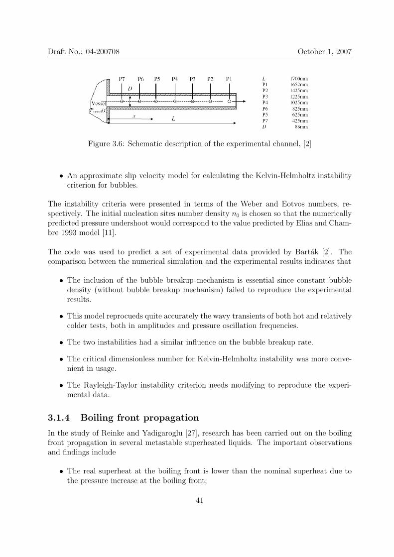
Figure 3.6: Schematic description of the experimental channel, [2]
• An approximate slip velocity model for calculating the Kelvin-Helmholtz instabilitycriterion for bubbles.
The instability criteria were presented in terms of the Weber and Eotvos numbers, re-spectively. The initial nucleation sites number density n0 is chosen so that the numericallypredicted pressure undershoot would correspond to the value predicted by Elias and Cham-bre 1993 model [11].
The code was used to predict a set of experimental data provided by Bartak [2]. Thecomparison between the numerical simulation and the experimental results indicates that
• The inclusion of the bubble breakup mechanism is essential since constant bubbledensity (without bubble breakup mechanism) failed to reproduce the experimentalresults.
• This model reprocueds quite accurately the wavy transients of both hot and relativelycolder tests, both in amplitudes and pressure oscillation frequencies.
• The two instabilities had a similar influence on the bubble breakup rate.
• The critical dimensionless number for Kelvin-Helmholtz instability was more conve-nient in usage.
• The Rayleigh-Taylor instability criterion needs modifying to reproduce the experi-mental data.
3.1.4 Boiling front propagation
In the study of Reinke and Yadigaroglu [27], research has been carried out on the boilingfront propagation in several metastable superheated liquids. The important observationsand findings include
• The real superheat at the boiling front is lower than the nominal superheat due tothe pressure increase at the boiling front;
41
Draft No.: 04-200708 October 1, 2007
• Above a certain superheat threshold, vaporization occurs only in boiling front andbelow a certain superheat threshold, no boiling front but only slow bubbling, whichagrees with previous studies;
• No significant influence of the cross-section area on the front velocity for pipe size inthe range from 14 to 80mm which is contrary to certain previous findings [13] whichsuggest an asymptotic threshold value at larger pipe diameters;
• The vaporization and fragmentation of the superheated liquid at the boiling frontappears to be self-amplified;
• The boiling front travels at a constant average velocity which is much lower than thelocal speed of sound. The measured velocity varies predominantly linearly with theliquid superheat;
• Linear empirical equations have been established between the velocity of boiling frontpropagation and the nominal superheat for butane, propane, and water;
• Most importantly, the boiling front had a velocity significantly lower thanthat expected from isentropic phase change.
Two flash fractions, χh for isenthalpic flash fraction and χs for isentropic flash fraction, aredefined as follows§
χs =sl1 − sl2
sv2 − sv2
<hl1 − hl2
hv2 − hv2
= χh =cpl∆T12
hLG2
= Ja
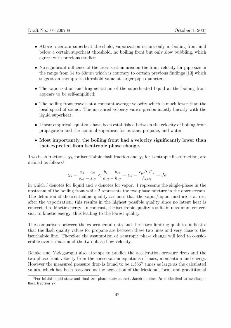
in which l denotes for liquid and v denotes for vapor. 1 represents the single-phase in theupstream of the boiling front while 2 represents the two-phase mixture in the downstream.The definition of the isenthalpic quality assumes that the vapor/liquid mixture is at restafter the vaporization; this results in the highest possible quality since no latent heat isconverted to kinetic energy. In contrast, the isentropic quality results in maximum conver-sion to kinetic energy, thus leading to the lowest quality.
The comparison between the experimental data and these two limiting qualities indicatesthat the flash quality values for propane are between these two lines and very close to theisenthalpic line. Therefore the assumption of isentropic phase change will lead to consid-erable overestimation of the two-phase flow velocity.
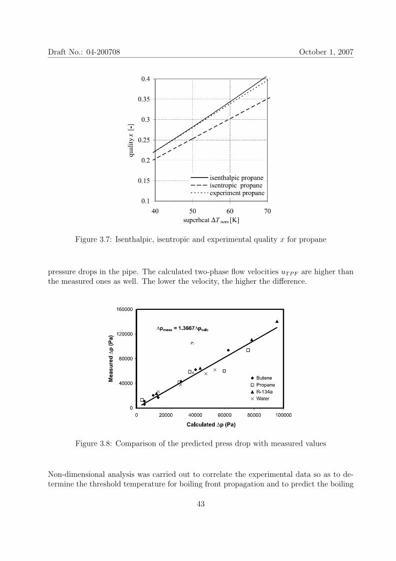
Reinke and Yadegaroglu also attempt to predict the acceleration pressure drop and thetwo-phase front velocity from the conservation equations of mass, momentum and energy.However the measured pressure drop is found to be 1.3667 times as large as the calculatedvalues, which has been reasoned as the neglection of the frictional, form, and gravititional
§For initial liquid state and final two phase state at rest, Jacob number Ja is identical to isenthalpicflash fraction χh.
42
Draft No.: 04-200708 October 1, 2007
Figure 3.7: Isenthalpic, isentropic and experimental quality x for propane
pressure drops in the pipe. The calculated two-phase flow velocities uTPF are higher thanthe measured ones as well. The lower the velocity, the higher the difference.
Figure 3.8: Comparison of the predicted press drop with measured values
Non-dimensional analysis was carried out to correlate the experimental data so as to de-termine the threshold temperature for boiling front propagation and to predict the boiling
43
Draft No.: 04-200708 October 1, 2007
front velocity ufrt as a function of the superheat. If the representative temperature isTsat,frt for all the fluids, the superheat at the threshold of boiling front propagation isgiven by
Ja∗thr = 10.11Pr0.971l (3.1)
and if the representative temperatures are Tini for liquid and Tsat,frt for gas,
Ja∗thr = 8.997Pr1.325l (3.2)
For the boiling front velocity ufrt, since the slopes of the correlation lines differed fromfluid to fluid, an average slop is used in deriving a general correlation.
Jathr = Ja∗thr
ρv(Tsat,frt)
ρl(Tini)(3.3)
Ca = 0.0813(Ja− Jathr) (3.4)
in which the capilary number Ca is defined as (µufrt)/σ.
It should be remarked that
• The highest initial temperature in this study is corresponding to approx. 0.81Tc.The real superheat at the boiling front is even lower than the one calculated fromthe initial temperature. Therefore this study mainly describes the superheated liquidbehavior in pre-BLEVE stage;
• The measured flash quality values are exactly on the isenthalpic line at lower super-heats. As the superheat increases, the experimental data deviates from the isenthalpicline and towards the isentropic line.
• The conclusion that no significant influence of the cross-section area on the frontvelocity is noticeable.
3.1.5 Tank in pool fire engulfment
A simple mathematical mode has been proposed [28], which describes dependences ofvarious parameters on time in an accident of LPG tank in pool fire engulfment. Theseparameters include temperature, pressure and mass of LPG, temperature of the vessels’wall and thermal protection layer.
The system of equations include empirical equations for the liquid vaporization, the tem-peratures of the liquid and the vessel wall, and the one-dimensional thermal diffusionequation for thermal layer.
44
Draft No.: 04-200708 October 1, 2007
The computed vessel pressure and temperature were compared with the experimental re-sults for different kinds of thermal layer protections.
In two cases of thick thermal layer 60mm and 10mm, poor agreements were observed inthe maximum vessel pressure in which the computation overestimated the maxima greatly.For the rest 6 cases of thin thermal layers or no thermal layers, the maxima were almostsuccessfully predicted except a small delay in the time for the maxima to be reached.
The predicted wall temperature as a function of time was poorly agreed with experimentaldata.
3.1.6 Open question in pre-BLEVE stage
The open question left for us in the pre-BLEVE stage is mainly the status of the liquid/two-phase mixture and the ambient at the moment of tank total disintegration, which includes
• Bubble number density, bubble volume distribution or void fraction in average;
• thermodynamic state of the liquid and the vapor, respectively;
• thermodynamic state of the ambient.
• the shape of liquid/two-phase mixture after tank total disintegration
To experimentally investigate above problems, more parameters besides the ones listed inTable (3.1) should be investigated, i.e. different crack increasing rates, different momentsof tank total disintegration, different durations of tank total disintegration etc.
To numerically solve above problems, fluid-structure coupling analysis must be performedto get the correct initial condition for the research in BLEVE stage.
However an easy way to simplify the pre-BLEVE stage is to assume that the pre-BLEVEstage lasts extremely short in time. The liquid can be regarded as undisturbed after thetank total disintegration. In this way, the initial conditions for BLEVE stage can be easilyachieved.
3.2 BLEVE stage
The BLEVE stage is the most important stage of a BLEVE event. If no chemical reactionafterwards, the output of the BLEVE stage is the output of the whole BLEVE event, nor-mally a rapind expansion of two-phase mixture following a blast wave propagating in the
45
Draft No.: 04-200708 October 1, 2007
air.
The feature of the BLEVE stage is rapidness. Some researchers reason that the rapindexpansion of the superheated liquid is due to the homogeneous bubble nucleation and thehigh vaporization rate at the superheat limit. In the lab-scale experiments, a single liquiddroplet is injected into a bubble column and gradually heated to be superheated. Suddenlythe droplet explodes. The behavior of the droplet and the bubble growth inside the dropletis recorded by high-speed photography, meanwhile the pressure perturbation is measured.Some researchers believe for real commercial Pressure-Liquefied-Gas, the heterogeneousnucleation will dominate the initial phase of the BLEVE stage due to the presence of therough tank wall and the impurities in the liquid. Therefore they also carried out studieson the role of heterogeneous nucleation in the BLEVE stage.
For the numerical simulation of the BLEVE stage, some simple numerical models havebeen developed which are able to describe the shock wave generated in BLEVE stage.Direct experimental validation is still required for those models.
3.2.1 Superheat limit and BLEVE
Thermodynamic stability analysis indicates that, for a pure liquid, the superheat-limitresults when
(∂p∂v
)T
= 0 (3.5)
An interesting correlation between the superheat limit temperature and the pressure wasdeveloped by Reid in [25] from the bubble-column data. In this study, TSL/Tc was plottedas a function of p/pc and found to increase with p/pc for several liquids and particularly
TSL/Tc ' 0.89 ∼ 0.90 when p = 1 atm
Reid also proposed a new method of estimating the superheat-limit temperature basedon the kinetic theory with which he could estimate the numerical values of the rate offormation of critical-size embryos and thus vapor bubbles from a given volume of liquid.If the nucleation rate is chosen to be 1012m−3s−1 , the superheat-limit temperature forn-pentane is 421K closing to the experimental value. Fortunately, the results are relativelyinsensitive to the choice of the nucleation rate¶.
An important result is that kinetic theory indicates no significant bulk nucleation until adefinite temperature is reached. Then, in a range of only a few degrees, the rate changes
¶The predicted value of TSL/Tc as a function of p/pc was plotted in curves which are in qualitativeagreement with the data from previous studies. Unfortunately, few data exist to test this prediction atthat moment.
46
Draft No.: 04-200708 October 1, 2007
from a value which is negligible small to a very large value.
Reid used his superheat-limit hypothesis to explain the explosion caused by rapid depres-surization of hot, saturated liquids in an accident of pressurized-liquid tank or BLEVE[26]. Two requirements were proposed for the possible explosion:
• The temperature of the hot (heated by fire) liquid must be above the superheat-limittemperature at 1 atm;
• The drop in tank pressure must be very rapid.
The strength of the explosion immediately following a tank failure has been linked to thedegree of superheat at the time the tank failed.
3.2.2 Prediction of the superheat limit
In the work of Abbasi et al. [1], attempts have been made to develop a framework withwhich superheat limit temperature TSL of a new substances can be theoretically deter-mined. Seven cubic equation of state (EOS) have been transformed and numerically solvedfor TSL.
A comparison between the predictions and the observed values reveals that for a largenumber of chemicals the transformed Redlich-Kwong EOS is able to predict TSL within1% deviation from the experimental values.
p =RT
v − b− a
T 1/2v(v + b)(3.6)
in which v is the specific volume; R = R/mM . Applying the mathematical description ofthe critical point
(∂p∂v
)∣∣∣Tc
= 0 and(∂2p
∂v2
)∣∣∣Tc
= 0
to Eqn.(3.6), they get the values of b and a in terms of critical volume as
b =vc
κand a =
κ(κ+ 1)2
(2κ+ 1)(κ− 1)2RT 3/2
c vc (3.7)
where κ = 22/3 + 21/3 + 1. vc can be further eliminated from the expressions of b and a,hence RK-EOS in reduced coordinates is
pr =3κTr
κvr − 1− κ2
T1/2r vr(κvr + 1)
(3.8)
47

Draft No.: 04-200708 October 1, 2007
When the concept of minimuzation of pressure at maximum superheat as given by Eqn.(3.5)is applied to above equation, it produces highly non-linear algebraic equations to be solvednumerically.
3.2.3 Bubble growth at the superheat limit
In the experimental study of Shepherd and Sturtevant [29], short-exposure photographsand fast-response pressure measurements have been used to construct a description of thecomplete explosion process of superheated droplets. An empirical model of evaporationafter onset of instability has been established.
The results showed that
• the measured superheat limits agreed well with published data;
• only one single bubble forms within the droplet during each explosion and the growthproceeds in microsecond time frame;
• the effective velocity of the vapor-liquid interface was high initially but reached aconstant value within a short time if the bubble expansion of the order of 5µs;
• a large-amplitude small-scale roughening (interfacial instability) of the bubble surfaceis observed in the early stage of the evaporation;
• a series of toroidal waves driven by vapor jetting form on the interface are observedafter the bubble has grown large enough to contact the outer edge of the droplet;
• violent oscillations of the bubble that occur on a millisecond time scale, after evap-oration of the liquid is complete, cause the disintegration of the bubble into a cloudof tiny bubbles.
From there results the authors were able to deduce that
• very high rates of mass transfer‖ occured from the liquid to the growing bubble whichmight be the result of the observed instability and wrinkling of the evaporatingsurface, the Landau mechamism of instability applies to rapid evaporation at thesuperheat limit and Rayleigh-Taylor instability applies to the bubble disintegration;
• the implied density of the vapor in the bubble was high;
‖The evaporative mass flux is two-order of magnitude greater than the one predicted by conventionalbubble-growth theories without account for the effects of instability. Indeed the evaporative mass flux isof the same order as the maximum possible one-way flux across a smooth interface given by kinetic theory,namely 1
4nc, where n is the number density and c is the mean molecular speed
48
Draft No.: 04-200708 October 1, 2007
• from energy considerations, it was likely that the bubble content was not single phasebut was made up of both dense vapor and liquid;
• The estimated mean density within the bubble is more than 1/2 of the critical densityfor butane, and of the order of the liquid density.
With the fraction θ of the bubble surface across which evaporation actually takes place,
the evaporation flux rate m0 and the bubble radius increasing rate ¯R assumed constant,an empirical model of evaporation after onset of instability are established.
Vb =4
3π
¯R3t3 (3.9)
Mb =4
3π
¯R2t3θ m0 (3.10)
ρeff = θm0
R(3.11)
dp
dt=
2ρ∞¯R2
τ
[¯R− θ
m0
ρl
](3.12)
in which Vb, Mb, ρeff and dp/dt are the bubble volume, the total mass within the bubble,the effective vapor density within the bubble and the far-field pressure, respectively.
The time for liquid initially contained a drop of radius R0 to completely boil is proportionalto R0:
t0 = R0
[θm0
ρl
¯R2
]− 13
(3.13)
The maximum far-field pressure at the end of the evaporative stage is proportional to t0,and therefore R0:
pmax =dp
dtt0 (3.14)
After the evaporative instability becomes nonlinear and saturated, the evaporation processseems to be quasi-steady:
• The bubble radius increasing at constant speed, R.
• The far-field pressure increasing at a roughly linear rate dp/dt.
• The evaporative flux is a constant m0.
• θ, the fraction of the bubble surface across which evaporation actually takes place,is assumed to be constant 0.5 calculated from the present experimental data.
49
Draft No.: 04-200708 October 1, 2007
3.2.4 Heterogeneous nucleation factor
In the study of Deligiannis and Cleaver [8], a two-fluid model has been used to evaluate theinitial depressurization of a subcooled or saturated liquid. The role of nucleation and itseffect on the interfacial area, and hence heat and mass transfer, is assessed and comparedwith available experimental data.
They derived the interfacial heat transfer qi as a function of the bubble number densityand the void fraction, in contrast to the arbitrarily assumed constant number density andbubble radius used in previous models
qi = 3.9n2/3b α1/3
v ·Nu · kl(Ti − Tk) (3.15)
in which Ti is the interfacial temperature; Tk is the temperature of phase k. The bubblenumber density nb is computed from one-dimensional transport equation
∂nb
∂t+ u
∂nb
∂z+ nb
∂u
∂z= HHOM +HHET −HCOAL (3.16)
in which HHOM , HHET , HCOLA are the change in nb arises from homogeneous nucleationin the bulk of the liquid, heterogeneous nucleation on the surfaces and the rate at at whichbubbles coalesce, respectively. Utilizing the conservation equations for mass and energytogether with the state equation ρv = ρv(p, hv), above equation can be written as
Dnb
Dt− nb
ρvc2v
Dp
Dt− nb
αv
Dαv
Dt= HHOM +HHET −HCOAL (3.17)
− nb
ρvαv
(miv + mNU) +nb
ρ2vαv
BCE[∂ρv
∂hv
]p
(3.18)
where cv is the speed of sound in the vapor phase; subscript NU stands for nucleation;BCE is the energy per unit volume transferred to the vapor when the liquid flashes [12].Once HHOM , HHET and HCOAL are known, above equation can be solved by the methodof characteristics.
In many experimental studies, the temperature difference is less than the superheat forhomogeneous nucleation. Therefore HHOM can be considered negligibly small and at thebeginning of a depressurization HCOAL might also be considered small.
Heterogeneous nucleation factor φ is introduced to derive an equation for heterogeneousnucleation rate from the one for homogeneous nucleation rate:
50
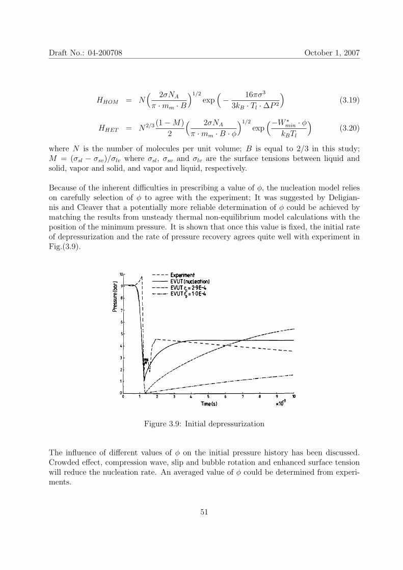
Draft No.: 04-200708 October 1, 2007
HHOM = N( 2σNA
π ·mm ·B)1/2
exp(− 16πσ3
3kB · Tl ·∆P 2
)(3.19)
HHET = N2/3 (1−M)
2
( 2σNA
π ·mm ·B · φ)1/2
exp(−W ∗
min · φkBTl
)(3.20)
where N is the number of molecules per unit volume; B is equal to 2/3 in this study;M = (σsl − σsv)/σlv where σsl, σsv and σlv are the surface tensions between liquid andsolid, vapor and solid, and vapor and liquid, respectively.
Because of the inherent difficulties in prescribing a value of φ, the nucleation model relieson carefully selection of φ to agree with the experiment; It was suggested by Deligian-nis and Cleaver that a potentially more reliable determination of φ could be achieved bymatching the results from unsteady thermal non-equilibrium model calculations with theposition of the minimum pressure. It is shown that once this value is fixed, the initial rateof depressurization and the rate of pressure recovery agrees quite well with experiment inFig.(3.9).
Figure 3.9: Initial depressurization
The influence of different values of φ on the initial pressure history has been discussed.Crowded effect, compression wave, slip and bubble rotation and enhanced surface tensionwill reduce the nucleation rate. An averaged value of φ could be determined from experi-ments.
51
Draft No.: 04-200708 October 1, 2007
‡In the following study of Deligiannis and Cleaver [9], they carefully investigated the het-erogeneous nucleation factor φ during a transient liquid expansion. φ is well-defined foran isolated bubble, but for swarms of bubbles it is statistical in nature and difficult todetermine analytically.
The calculated value of φ has been statistically correlated with the initial temperature ofthe liquid T0, the pressure drop ∆p = p(T0)− pmin, the time to the minimum pressure ∆tand the mean depressurization rate ∆p/∆t.
φ is found to be mainly dependent on the liquid superheat ∆p and T0.
φ ∼ T0, ∆p
The averaged value of φ for all the wall nuclei in the vessel should not depend on the rateof pressure release in the vessel, but only on the pressure and temperature at the positionswhere nucleation is most dominant; in this case where the pressure is a minimum. For veryrapid discharges, the temperature of the liquid at this point varies little from the initialtemperature. Hence
φ ∼ T0, pmin
For both the water and the freon test, pmin shows a close correlation with T0
pmin ∼ T0
therefore φ should only be a function of T0
φ = φ(T0)
or in reduced temperatureφ = φ(T0/Tc)
The correlation of φ with T0/Tc suggests that very fast discharges (> 2000 bar/s) providea robust method of attempting to quantify the heterogeneous nucleation factor. Since Tl
hardly changes from T0 during the nucleation process, the functional relation of φ with Tl
may be of value of modeling non-equilibrium two-phase flows in which nucleation is knownto play an important role.
3.2.5 Numerical simulations for BLEVE stage
In the study of van den Berg et al. [33], [34], a new method is presented to calculate theblast effects originating from an exploding vessel of liquefied gas.
52
Draft No.: 04-200708 October 1, 2007
A safe assumption they made on the vapour source strength or the flash-evaporation rate isthat the evaporation process is expansion-controlled∗∗. In such cases, the vapor pressureof a flashing liquid is imposed as the boundary condition for the gas dynamics of expansion.
An acoustic blast model was developed from the solution of the wave equation. With theassumption of linearly growing liquid release rate, the blast overpressure can be computedfrom
• a volume source in a half-space††:
∆p
p0
=γ
2πrc20
2V χϕ
(∆t)2
• a volume source in a tube:∆p
p0
=γ
2Ac0
V χϕ
∆t
where ∆p is the wave overpressure; p0 is the ambient pressure; c0 is the ambient speed ofsound; A is the cross-sectional area of the tube; V is the volume of the liquefied gas; χis the flash fraction and ϕ is the liquid-to-vapour expansion factor; r is the distance fromsource; t is time.
The computational results from various release times indicate the magnitue and dura-tion of the blast effect from a collapsing vessel of liquefied gas is highly dependent onthe release time and thereby on the exact rupture mode of the vessel and the consequentliquid release development. The authors remark that any experimental observations onBLEVE blast effects can only make any sense if the rupture mode of the vessels used andthe consequent release scenario can be controlled and are fully repeatable. The modellingshowed that the rupture of a pressure vessel containing a liquefied gas in free space developsblast of a significant strength only if the vessel nearly instantaneously disintegrates. Theblast effects could be minor if the crack and the consequent release of a vessel take just afraction of a second, i.e., 0.5s.
The gas dynamics of the expanding vapour and the sourrounding atmosphere was furthercomputed by numerically solving the Euler equations and
• if the rupture of the vessel and the subsequent liquid release are nearly instantaneous,the boundary conditions consists in the vapour pressure of the superheated liquid;
∗∗It means that intrinsically the evaporation of superheated liquid can occur infinitely fast, thereforeextrinsic circumstances including the liquid release rate and the gas dynamics (inertia) of the vapour andthe surrounding air will determine the evaporation rate.††In [33], (ϕ− 1) replaces ϕ in all these equations.
53
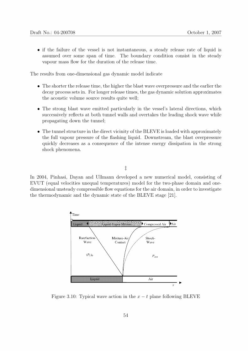
Draft No.: 04-200708 October 1, 2007
• if the failure of the vessel is not instantaneous, a steady release rate of liquid isassumed over some span of time. The boundary condition consist in the steadyvapour mass flow for the duration of the release time.
The results from one-dimensional gas dynamic model indicate
• The shorter the release time, the higher the blast wave overpressure and the earlier thedecay process sets in. For longer release times, the gas dynamic solution approximatesthe acoustic volume source results quite well;
• The strong blast wave emitted particularly in the vessel’s lateral directions, whichsuccessively reflects at both tunnel walls and overtakes the leading shock wave whilepropagating down the tunnel;
• The tunnel structure in the direct vicinity of the BLEVE is loaded with approximatelythe full vapour pressure of the flashing liquid. Downstream, the blast overpressurequickly decreases as a consequence of the intense energy dissipation in the strongshock phenomena.
‡In 2004, Pinhasi, Dayan and Ullmann developed a new numerical model, consisting ofEVUT (equal velocities unequal temperatures) model for the two-phase domain and one-dimensional unsteady compressible flow equations for the air domain, in order to investigatethe thermodynamic and the dynamic state of the BLEVE stage [21].
Figure 3.10: Typical wave action in the x− t plane following BLEVE
54
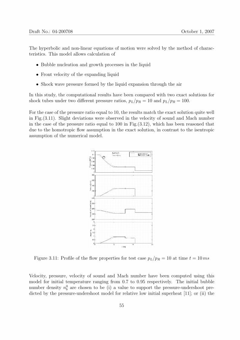
Draft No.: 04-200708 October 1, 2007
The hyperbolic and non-linear equations of motion were solved by the method of charac-teristics. This model allows calculation of
• Bubble nucleation and growth processes in the liquid
• Front velocity of the expanding liquid
• Shock wave pressure formed by the liquid expansion through the air
In this study, the computational results have been compared with two exact solutions forshock tubes under two different pressure ratios, pL/pR = 10 and pL/pR = 100.
For the case of the pressure ratio equal to 10, the results match the exact solution quite wellin Fig.(3.11). Slight deviations were observed in the velocity of sound and Mach numberin the case of the pressure ratio equal to 100 in Fig.(3.12), which has been reasoned thatdue to the homotropic flow assumption in the exact solution, in contrast to the isentropicassumption of the numerical model.
Figure 3.11: Profile of the flow properties for test case pL/pR = 10 at time t = 10ms
Velocity, pressure, velocity of sound and Mach number have been computed using thismodel for initial temperature ranging from 0.7 to 0.95 respectively. The initial bubblenumber density n0
b are chosen to be (i) a value to support the pressure-undershoot pre-dicted by the pressure-undershoot model for relative low initial superheat [11]; or (ii) the
55
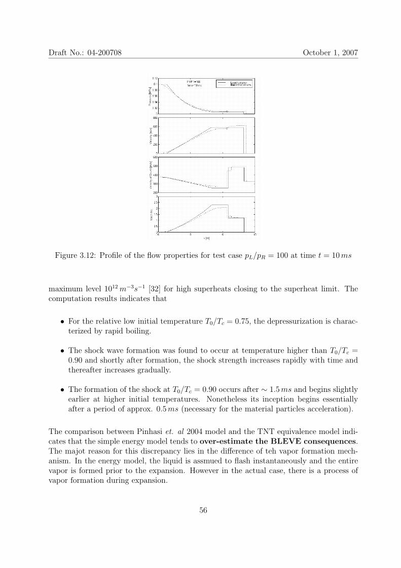
Draft No.: 04-200708 October 1, 2007
Figure 3.12: Profile of the flow properties for test case pL/pR = 100 at time t = 10ms
maximum level 1012m−3s−1 [32] for high superheats closing to the superheat limit. Thecomputation results indicates that
• For the relative low initial temperature T0/Tc = 0.75, the depressurization is charac-terized by rapid boiling.
• The shock wave formation was found to occur at temperature higher than T0/Tc =0.90 and shortly after formation, the shock strength increases rapidly with time andthereafter increases gradually.
• The formation of the shock at T0/Tc = 0.90 occurs after ∼ 1.5ms and begins slightlyearlier at higher initial temperatures. Nonetheless its inception begins essentiallyafter a period of approx. 0.5ms (necessary for the material particles acceleration).
The comparison between Pinhasi et. al 2004 model and the TNT equivalence model indi-cates that the simple energy model tends to over-estimate the BLEVE consequences.The majot reason for this discrepancy lies in the difference of teh vapor formation mech-anism. In the energy model, the liquid is assmued to flash instantaneously and the entirevapor is formed prior to the expansion. However in the actual case, there is a process ofvapor formation during expansion.
56
Draft No.: 04-200708 October 1, 2007
3.2.6 Open questions in BLEVE stage
The goal of research in BLEVE stage in our project is to quantitatively describe how thebubble nucleation/vaporization proceeds in the real BLEVE stage.
In the lab-scale experiments, we can use the vessel of polished inner wall and purified liquidto suppress the heterogeneous nucleation. But we can not do that in a real-scale BLEVEevent. The difference between the lab-scale experiments and the real-scale BLEVE eventis not only the length scales, but also the volume density of the heterogeneous sites, therelative ratios between various length scales etc. We can research various bubble nucle-ation/vaporization in the lab, but for the engineering computation, we must either includeall the possibilities or use a smart average to weight all the possibilities.
Simply to say, we must be able to mathematically describe all the possible bubble nucle-ation/vaporization for a real BLEVE event, including the onset condition, the nucleationrate and the vaporization rate. This is the most tricky and challenging problem in ourproject.
3.3 Post-BLEVE stage
The post-BLEVE stage, accordig to our definition, is an optional stage of a BLEVE event.Due to the flammability of most PLG stored in commercial tanks, it is frenquently occur-ring in a BLEVE event. Therefore the chemical explosion in post-BLEVE stage has beenwidely researched and many BLEVE-related studies are often involving fires in differentformats, including pool fire, jetting fire, fireball etc.
To intepret the chemical explosion in post-BLEVE stage, we must be able to quantitivelydescribe the status of the two-phase PLG and the ambient air before the chemical reationcommences. All these are based on a clear and definitive understanding the rapid expan-sion of the highly superheated liquid in pre-BLEVE and BLEVE stages. In our project, wewill mainly concentrate on pre-BLEVE and BLEVE stage of the BLEVE event and leavethe post-BLEVE stage for future studies.
3.4 Summary
57
Chapter 4
Equations and models for two-phaseflow
In this chapter, we will summarize the conservative equations and constitutive models fortwo-phase flow and bubble vaporization.
The traditional conservative equations have two simplified formats for two-phase flow,EVET (equal velocity and equal temperature) and EVUT (equal velocity and unequaltemperature) models. The latter have been widely used in the numerical simulation oftwo-phase flows.
The bubble vaporization in two-phase flow is a process of mass and heat transfer, thereforethe source terms in the continuity, momentum and energy equations need to be describedby constitutive models which include the the mass transfer rate at the interface, interfacialfriction, wall friction, interfacial heat transfer and wall heat transfer into the liquid andthe vapor phase, respectively.
The reference in this paper includes: [4], [8], [15], [17], [20], [21], [22], [32], [33] and [34].
58
Draft No.: 04-200708 October 1, 2007
4.1 Conservative equations
In rapid expansion phenomena, viscous and heat diffusion are relatively slow processesthat entail negligibel effects. Neglecting viscous and axial heat flux terms, the conservationequations for the flow are therefore:
∂
∂t(αkρk) +
1
A
∂
∂x(Aαkρkuk) = Γi,k (4.1)
∂
∂t(αkρkuk) +
1
A
∂
∂x(Aαkρku
2k) + αk
∂pk
∂x
= Γi,kuk − fi,k − fw,k − αkρkg∂Z
∂x(4.2)
∂
∂t
[αkρk
(hk +
1
2u2
k
)]+
1
A
∂
∂x
[Aαkρkuk
(hk +
1
2u2
k
)]− αk
∂pk
∂t
= qi,k + qw,k + fi,kuk + Γi,k
(hk +
1
2u2
k
)− αkρkukg
∂Z
∂x(4.3)
In these equations, the subscript k (l or v) denotes the phase (liquid or vapor, respectively).The source terms Γi,k, fi,k, fw,k, qi,k and qw,k are the mass transfer rate at the interface,interfacial friction, wall friction, interfacial heat transfer and wall heat transfer into phasek per unit volume, respectively. Likewise, A is the cross-section area of the duct, Z is theelevation and x is the space independent variables.
The summation of the liquid and gaseous volume fractions equals by definition unity (αl +αv = 1). It is assumed that gravity is the only influential external force. For conservationof mass, momentum and energy at any two-phase interface, the following relations musthold:
Γi,v + Γi,l = 0 (4.4)
Γi,vuv − fi,v + Γi,lul − fi,l = 0 (4.5)
qi,v + fi,vuv + Γi,v
(hv +
1
2u2
v
)+ qi,l + fi,lui,l + Γi,l
(hl +
1
2u2
l
)= 0 (4.6)
4.1.1 Simplified conservative equations: EVET model
The EVET model is based on the assumptions that the phases are of equal local pressures(i.e. pl = pv = p), equal temperatures (i.e. Tv = Tl = T ), and no slip conditions (uv =ul = u and fi,k = 0). According to these assumptions, the one-dimensional conservationequations reduce to (similar to single phase equations) [22]:
59
Draft No.: 04-200708 October 1, 2007
∂ρm
∂t+
∂
∂x(ρmu) = −ρmu
1
A
dA
dx(4.7)
ρm∂u
∂t+ ρmu
∂u
∂x+∂p
∂x= −fw − ρmg
∂Z
∂x(4.8)
ρm∂hm
∂t+ ρmu
∂hm
∂x− ∂p
∂t− u
∂p
∂x= qw + fwu (4.9)
where the mixture density and the mixture enthalpy are
ρm = αlρl + αvρv (4.10)
hm =αlρlhl + αvρvρvhv
ρm
(4.11)
To complete the sef of governing equations, the thermal and equations of states for satu-rated fluid conditions are introduced:
ρk = ρk,sat(p), hk = hk,sat(p) (4.12)
4.1.2 Simplified conservative equations: EVUT model
The EVUT (equal velocity, unequal temperature) model is the simplest way of describ-ing the sudden depressurization of an initially subcooled or saturated liquid containedin a vessel. For EVUT model, the existence of equal local pressure between phases (i.e.pl = pv = p) and no slip conditions (i.e. ul = uv = u and fi,k = 0) are assumed and thetemperature difference between two phases is allowed.
The EVUT model in Pinhasi et al. [21] and [22] reads
∂
∂t(αkρk) +
∂
∂x(αkρku) = Γi,k − αkρku
1
A
dA
dx(4.13)
ρm∂u
∂t+ ρmu
∂u
∂x+∂p
∂x= −(fw,l + fw,v)− ρmg
dZ
dx(4.14)
αkρk∂hk
∂t+ αkρku
∂hk
∂x+ αk
∂p
∂t− αku
∂p
∂x= qi,k + qw,k + fw,ku (4.15)
The mixture density is given by ρm = αvρv + αlρl and the set of equations is subject tothe thermodynamic state equation of each phase: ρk = ρk(p, hk).
60
Draft No.: 04-200708 October 1, 2007
‡The EVUT model in Deligiannis & Cleaver [8] is
∂
∂t(αkρk) +
1
A
∂
∂x(Aαkρku) = Γi,k + ΓNU (4.16)
∂
∂t(αkρku) +
1
A
∂
∂x(Aαkρku
2) + αk∂p
∂x= Γi,ku− fi,k − fw,k
−αkρkg∂Z
∂x+ ΓNUu (4.17)
∂
∂t
[αkρk
(hk +
u2
2
)]+
1
A
∂
∂x
[Aαkρku
(hk +
u2
2
)]− αk
∂p
∂t
= qi,k + qw,k + fi,ku+ Γik
(hk +
u2
2
)i− αkρkug
∂Z
∂x+BCE (4.18)
The subscript w, i and NU denote transfer from the wall, the interface and the nucleation,respectively. BCE is the energy per unit volume transferred to the vapor when the liquidflashes.
4.2 Constitutive models
Constitutive equations for wall and interfacial heat and mass transfer must be providedfor closure of the conservation equations for two-phase flow.
4.2.1 Interfacial source terms
According to [21] and [22], the interfacial mass and heat transfer have below relations.
Γi,vhLG = qi,net (4.19)
qi,net = Aiq′′i,net (4.20)
Γi,v = AiΓ′′i,net (4.21)
where q′′i,net and Γ′′i,net are the interfacial transfer rate per square meter for heat and mass,
respectively; Ai, the interfacial area density, is defined to be the interfacial area per unit
61
Draft No.: 04-200708 October 1, 2007
volume. If the bubbles are assumed to be spherical and having the similar diameters, Ai
can be expressed to be
Ai = 4πR2nb (4.22)
where nb is the number density of nucleation sites. Also the void fraction can be writtenas
αv =4
3πR3nb (4.23)
The bubble growth is assumed to be heat diffusion controlled. Therefore the heat supplyto the bubble interface can be expressed as
q′′i,net = h[Tl − Tsat(pl)] (4.24)
The heat transfer coefficient h can be derived from solutions for the diffusion rate of heattransport from a liquid at constant superheat state to a bubble interface, which is
h =klNu
2Rb
(4.25)
in which the Nusselt number is a function of the Jacob number,
Nu =12
π
[1 +
1
2
( π
6Ja
)2/3
+π
6Ja
](4.26)
Ja =cp,lρl(Tl − Tsat)
ρvhLG
(4.27)
The unknowns in above equations are R, nb and Γ′′i,net. If the void fraction can be solvedfrom the two-phase EVUT model, at least one more equation is needed to solve the inter-facial source terms.
In Pinhasi et al. [21], the net inerfacial mass transfer flux (or the net evaporation rate) isgiven [see [32]]
Γ′′i,net =psat − pv√2πmmkBT
(4.28)
In Pinhasi et al. [22], a bubble breakup model is developed for solving the number densityof the bubbles nb.
‡A new model for the interfacial heat transfer was developed in term of the bubble numberdensity and the void fraction [8]
62
Draft No.: 04-200708 October 1, 2007
qi = 3.9n2/3b α1/3
v ·Nu · kl · (Ti − Tk) (4.29)
where subscript k denotes liquid or vapor, respectively. Instead of arbitrarily assumingconstant number density and bubble radius, they use a transport equation for the numberdensity of bubbles nb for one-dimensional flow
∂nb
∂t+ u
∂nb
∂z+ nb
∂u
∂z= HHOM +HHET −HCOAL (4.30)
In most experimental studies the temperature difference is less than the superheat forhomogeneous nucleation. Bubble generation does not occur in the bulk of the liquid butmainly on the walls of the container or on impurities in the liquid. Therefore, HHOM
can be considered negligible small. At the beginning of a depressurization HCOAL mightalso be considered small. Hence the nucleation rate is mainly dependent on heterogeneousnucleation rate, given by Blander and Katz [4].
HHET = N2/3 (1−m)
2
( 2σNA
π ·mm ·B · φ)1/2
exp(−W ∗
min · φkBTl
)(4.31)
where N is the number of molecules per unit volume; B is equal to 2/3 in this study;m = (σsl−σsv)/σlv where σsl, σsv and σlv are the surface tensions between liquid and solid,vapor and solid, and vapor and liquid, respectively.
φ is the heterogeneous factor, < 1, which physically implies that the molecular clustersformed on a rough surface or suspended particles need less energy to survive. Bubblesformed in this manner assume a shape bounded by a plane and a portion of sphericalsurface. ξ is the contact angle at the bubble surface. Blander and Katz [4] show that φand ξ are linked by
φ =2− 3cosξ + (cosξ)3
4(4.32)
4.2.2 Wall source terms
The source terms between the wall and the two-phase flow are descibed by following modelsin [20]. The term for the channel wall heat transfer, qw,k to the vapor (k = v) or liquid(k = l) is connected to the void fraction as
qw,k = αkqw (4.33)
The total heat flux qw must be supplie as input the program as a function of the positionx along the channel. For adiabatic flow conditions there is not external heat input, thusqw = 0.
For single-phase liquid flow, the wall friction per unit volume of the mixture is
63
Draft No.: 04-200708 October 1, 2007
f 1phw,k = αkρkfw
ψ
A=
1
2αkρku
2Cf4
D(4.34)
where ψ is the duct perimeter (for a pipe ψ = πD); Cf is the friction coefficient.
For two-phase flow, a friction multiplier, η2, is incorporated so that
f 2phw,k = αkρkfw
ψ
A= f 1ph
w,k ·(η2ρm
ρl
)(4.35)
The friction coefficient Cf dependence on the Reynolds is
Cf =
16/ReD ReD < ReD,cr
0.046/ReD ReD > ReD,cr(4.36)
where the critical Reynolds for laminar-turbulence transition, ReD,cr = 1462.27.
The two-phase friction multipliers equations adopted in term of quality, χ, are
αv < 0.3 η2 =[1 + χ
(ρl
ρv− 1
)]0.81 + χ
[(3.5µv+2µl)ρl
(µl+µv)ρv− 1
]0.2
0.3 < αv < 0.8 η2 =[1 + χ
(ρl
ρv− 1
)]0.81 + χ
[3.5 ρl
ρv− 1
]0.2
0.8 < αv < 0.95 η2 =[1 + χ
(ρl
ρv− 1
)]0.81 + χ
[µlρl
µvρv− 1
]0.2
αv > 0.95 η2 =[1 + χ
(ρl
ρv− 1
)]1.8(µv
µl
)0.2(ρv
ρl
)0.8
(4.37)
For homogeneous flow, the flash quality χ = αvρv/ρm.
4.3 Specific models
4.3.1 Acoustic volume source term
In the study of van den Berg et. al [33] and [34], they derive a volume source term for gasexplosion using the acoustic volume source [17] as an analogue.
• a volume source in a half-space:
∆p
p0
=γ
2πrc2∞
dΦ
dt
64
Draft No.: 04-200708 October 1, 2007
• a volume source in a tube:∆p
p0
=γ
2Ac∞Φ
where Φ is the volume source strength, γ is the ratio of specific heats and c∞ is the am-bient speed of sound. A striking feature is that a steady release of superheated liquid inthree-dimensional space does not give rise to any overpressure while it does give rise toblast in a tube.
With the assumption of linearly growing liquid release rate, the blast overpressure in ahalf-space can be computed from
∆p
p0
=γ
2πrc2∞
2V χϕ
(∆t2)(4.38)
and the blast overpressure in a tunnel tube can be computed from
∆p
p0
=γ
2Ac∞
V χϕ
∆t(4.39)
in which a flash fraction χ = 50% and a liquid-to-vapor expansion factor ϕ = 260 areapproximated for propane.
4.3.2 Crack opening and choked flow
In 1996, Lenclud and Venart established a model for the observed crack propagation andopening on pressure tanks [15]. Crack lengths are obtained from high speed cinematogra-phy. Crack widths are assumed to be the sum of two components, an elastic displacementand a plastic displacement.
The elastic displacement ∆ is derived as a function of the crack length and the internalpressure from LEFM, Linear Elastic Fracture Mechanism, using crack opening displace-ment theory.
To introduce plastic displacement into the mode, they made two assumptions:
• the crack shape after the vent is elliptical;
• the shape aspect ratio C, i.e. the ratio of the length a to the plastic deformationwidth w, is constant over time.
As a result, half the actual crack width is the sum of the elastic and plastic components:
b =a
C+
∆
2
65
Draft No.: 04-200708 October 1, 2007
and the crack area is then:
Acrk = πa2( 1
C+
∆
2a
)
The crack length extension can be inferred to be a double step process, each of whichproceeds at constant velocity:
0 < t < t1 2a = u1t
t1 ≤ t < tAf 2a = u2t+ C2
t ≥ tAf 2a = 2lf
in which tAf is the timing of final crack length and 2lf is the final crack length and thevalues of u1, t1, u2 and C2 are determined by high speed cinematography. Therefore themodel for crack area as a function of time and internal pressure can be derived.
A choked flow model is first presented in this study in which a time-varying area and adischarge coefficient are introduced. The establishment of choked flow is assumed instan-taneous, the flow here is considered to be choked during the whole process, the process isconsidered isentropic and the gas perfect.
The equation for internal pressure is
p = p0
( p′p0
)−(γ−1)/(2γ)
+γ − 1
2
( 2
γ + 1
)0.5(γ+1)/(γ−1)
+CDA
′crk∆t
Vv
√γp0
ρ0
−2γ/(γ−1)
(4.40)
in which p0 and ρ0 are the initial density and pressure of the gas, respectively. p′ and A′crk
represent the pressure of the gas and the crack area at previous moment, respectively. CD
is the discharge coefficient. ∆t is the time step. Vv is the volume of the gas.
4.3.3 Bubble breakup model
The conservation equation for the bubbel number density nB is given in Pinhasi et al. [22]:
∂nb
∂t+
∂
∂z(nbu) = ψ (4.41)
where ψ is the intensity of the bubble breakup, given by the Kelvin-helmholtz and Rayleigh-Taylor instabilities respectively.
66
Draft No.: 04-200708 October 1, 2007
4.3.4 Slip velocity model
To calculate the Kelvin-Helmholtz instability criterion for bubbles, one must know thebubble dimension, the mixture properties and the difference between the phase velocities(the wlip velocity).
If the wlip velocity between phases is much smaller than the flow average velocity, |uv −ul| ¿ |u|, one can write the material derivatives as Dv/Dt ' Dl/Dt and the vapor equationof motion is
2ρv
ρl
Duv
Dt− 3
Dul
Dt+D(∆u)
Dt+ (∆u)
1
Vb
DVb
Dt=
1
Vb
Γ
ρl
(∆u)− 2
ρlVb
fD (4.42)
in which ul and uv are the velocities for liquid and vapor, respectively, ∆u = uv − ul; Γ isthe evaporation rate; Vb is the bubble volume and fD is the drag force on a bubble.
67
Bibliography
[1] Tasneem Abbasi, Brian A. Clarke, and S.A. Abbasi. Accidental risk of superheatedliquids and a framework for predicting the superheat limit. Journal of Loss Preventionin the Process Industries, 20(2):165–181, March 2005.
[2] J. Bartak. A study of the rapid depressurization of hot water and the. dynamics ofvapour bubble generation in superheated water. International Journal of MultiphaseFlow, 16(5):789–798, 1990.
[3] A.M. Birk, Z. Ye, J. Maillette, and M. Cunningham. Hot and cold bleves: Observationand discussion of two different kinds of bleves. In AiChE Heat Transfer Conference,AiChE Symposium Series, 1993.
[4] M. Blander and J. Katz. Bubble nucleation in liquids. AIChE Journal, 21(5):833–848,1975.
[5] Christopher E. Brennen. Cavitation and Bubble Dynamics. Oxford University Express,1995.
[6] S.N. Chen, J.H. Sun, and G.Q. Chu. Small scale experiments on boiling liquid ex-panding vapor explosions: Vessel over-pressure. Journal Of Loss Prevention In TheProcess Industries, 20(1):45–51, January 2007.
[7] C.F. Delale, J. Hruby, and F. Marsik. Homogeneous bubble nucleation in liquids: Theclassical theory revisited. Journal of Chemical Physics, 118(2):792–806, 2003. CitedBy (since 1996): 5.
[8] P. Deligiannis and J. W. Cleaver. Role of nucleation in the initial phases of a rapiddepressurization of a subcooled liquid. International Journal of Multiphase Flow,16(6):975–984, 1990. Cited By (since 1996): 8.
[9] P. Deligiannis and J. W. Cleaver. Determination of the heterogeneous nucleationfactor during a transient liquid expansion. International Journal of Multiphase Flow,18(2):273–278, 1992. Cited By (since 1996): 5.
[10] M.D. Donne and M.P. Ferranti. The growth of vapor bubbles in superheated sodium.International Journal Of Heat And Mass Transfer, 18(4):477–493, 1975.
68
Draft No.: 04-200708 October 1, 2007
[11] E. Eliasa and P.L. Chamber. Flashing inception in water during rapid decompression.Journal of Heat Transfer, 115:231–238, February 1993.
[12] J. Frenkel. Kinetic Theory of Liquids. Dover Publications, New York, 1955.
[13] M.A. Grolmes and H.K. Fauske. Axial propagation of free surface boiling into su-perheated liquids in vertical tubes. In Proceedings of the Fifth International HeatTransfer Conference, volume 4 of Paper B1.7, pages 30–34. Japan Soc. Mech. Eng.,Soc. Chem. Eng., 1974.
[14] Satish G. Kandlikar, Masahiro Shoji, and Vijay K. Dhir, editors. HANDBOOK OFPHASE CHANGE: Boiling and Condensation. TAYLOR & FRANCIS, 1999.
[15] J. Lenclud and J.E.S. Venart. Single and two-phase discharge from a pressurizedvessel. Revue Generale de Thermique, 35(416):503–516, 1996. Cited By (since 1996):2.
[16] E. Leprette. Le bleve, phenomenologie et modelisation des effets thermiques. Technicalreport, INERIS, 2002.
[17] J. Lighthill. Waves in fluids. Cambridge University Press, 1978.
[18] M. Matsumoto. Molecular dynamics of fluid phase change. Fluid Phase Equilibria,144(1-2):307–314, 1998. Cited By (since 1996): 19.
[19] C.A. McDevitt, C.K. Chan, F.R. Steward, and K.N. Tennankore. Initiation step ofboiling liquid expanding vapour explosions. Journal of Hazardous Materials, 25(1-2):169–180, 1990. Cited By (since 1996): 3.
[20] G.A. Pinhasi. Source Term Modeling of Gas and Liquid Release from Breached Pres-sure Vessel. PhD thesis, Tel-Aviv University, 2001.
[21] G.A. Pinhasi, A. Dayan, and A. Ullmann. Numerical model for boiling liquid vaporexplosion (bleve). pages 1820–1830, 2004.
[22] G.A. Pinhasi, A. Dayan, and A. Ullmann. Numerical model for bubbels break-upduring blowdown. pages 12425–12439, 2005.
[23] Andrea Prosperetti and Milton S. Plesset. Vapour-bubble growth in a superheatedliquid. Journal of Fluid Mechanics, 85(pt 2):349–368, 1978. Cited By (since 1996):37.
[24] Richard W. Prugh. Quantitative evaluation of ’bleve’ hazards. Journal of Fire Pro-tection Engineering, 3(1):9–24, 1991. Cited By (since 1996): 10.
[25] R.C. Reid. Superheated liquids. American Scientist, 64(2):146–156, 1976. Cited By(since 1996): 26.
69
Draft No.: 04-200708 October 1, 2007
[26] R.C. Reid. Possible mechanism for pressurized-liquid tank explosions or bleve’s. Sci-ence, 203(4386):1263–1265, 1979. Cited By (since 1996): 25.
[27] P. Reinke and G. Yadigaroglu. Explosive vaporization of superheated liquids by boilingfronts. International Journal of Multiphase Flow, 27(9):1487–1516, 2001. Cited By(since 1996): 8.
[28] Yu N. Shebeko, I.A. Bolodian, V.N. Filippov, V.Y. Navzenya, A.K. Kostyuhin, P.M.Tokarev, and E.D. Zamishevski. A study of the behaviour of a protected vessel contain-ing lpg during pool fire engulfment. Journal of Hazardous Materials, 77(1-3):43–56,2000. Cited By (since 1996): 6.
[29] J.E. Shepherd and B. Sturtevant. Rapid evaporation at the superheat limit. Journalof Fluid Mechanics, 121:379–402, 1982.
[30] M. Shusser and D. Weihs. Explosive boiling of a liquid droplet. International Journalof Multiphase Flow, 25(8):1561–1573, 1999. Cited By (since 1996): 6.
[31] M. Shusser, T. Ytrehus, and D. Weihs. Kinetic theory analysis of explosive boilingof a liquid droplet. Fluid Dynamics Research, 27(6):353–365, 2000. Cited By (since1996): 7.
[32] V. P. Skripov. Metastable Liquids. Wiley, 1974.
[33] A.C. Van Den Berg, M.M. Van Der Voort, J. Weerheijm, and N.H.A. Versloot.Expansion-controlled evaporation: A safe approach to bleve blast. Journal of LossPrevention in the Process Industries, 17(6):397–405, 2004. Cited By (since 1996): 6.
[34] A.C. Van Den Berg, M.M. Van Der Voort, J. Weerheijm, and N.H.A. Versloot. Bleveblast by expansion-controlled evaporation. Process Safety Progress, 25(1):44–51, 2005.
[35] J.E.S. Venart, G.A. Rutledge, K. Sumathipala, and K. Sollows. To bleve or not tobleve: anatomy of a boiling liquid expanding vapor explosion. Process Safety Progress,12(2):67–70, 1993. Cited By (since 1996): 8.
[36] J.E.S. Venart, K.F. Sollows, K. Sumathipala, G. A. Rutledge, and X. Jian. Boilingliquid compressed bubble explosions: Experiments/models, 1993. Cited By (since1996): 4.
[37] M. Volmer and A. Weber. Nucleus formation in supersaturated systems. Z. physik.Chem., 119, 1926.
70