solution vmt ws0607
TRANSCRIPT

Chair of Machine Tools Written Exam Task 1 P. 1/39
Esser Virtual Machine Tool Date: F07
SOLUTION
Machine Tool Design
Total score : 9.0 Points
1.1 Turning lathes
In the scetch below a turning lathe is shown with its basic components. Please fill in the correct names of the main components of the machine tool. (2.5 pts)
1.2 How can the design of a lathe help to reduce thermal errors using an inclined machine bed (slant bed) (please answer in one sentence)? (1 pt.)
The slant-bed design enables a quick removal (0.5 pts.) of the hot chips (0.25 pts.) and the cooling lubricant (0.25 pts.).
head stock (0.5 pts.) cross slide (0.5 pts.)
bed (0.5 pts.) longitudinal slide (0.5 pts.)
tail stock (0.5 pts.)

Chair of Machine Tools Written Exam Task 1 P. 2/39
Esser Virtual Machine Tool Date: F07
SOLUTION
1.3 Classification of manufacturing systems based on degree of automation
Please list the 5 degrees of automation in machine tools and state the typical features of automation. (3.75 pts)
Classification name Automation feature
1) _machine tool______ Generation of cutting motion / feed / process forces_
2) _NC-machine tool____ Automated control of machining sequences_______
3) _manufacturing centre_ Automated tool exchange with tool storage________
4) _manufacturing cell___ Aut. exchange of work piece with work piece storage
5) _transfer line, FMS __ Aut. flow of work piece and tool between machines_
Each classification name: 0.25 pts, each matching feature: 0.5 pts

Chair of Machine Tools Written Exam Task 1 P. 3/39
Esser Virtual Machine Tool Date: F07
SOLUTION
1.4 Force flux in machine tools
Scetch the force flux for a force load in direction of the y-axis. Start with defining the load. (1.75 pts.)
force load on cutter
0.25 pts. for each
feature of the scetch:
1. load
2. spindle bearing
3. Z-guide
4. Z-drive (no effect)
5. Y-guide (no effect)
6. Y-drive
7. table guide

Chair of Machine Tools Written Exam Task 3 P. 4/39
R. Meidlinger Virtual Machine Tool Date: F07
SOLUTION
Construction and Design of Structural Components
Total score : 10,0 Points
3.1 Static and Dynamic Characteristics of Machine Tools
The static and dynamic behaviour of machine tools can be described by frequency response functions (FRFs) of compliance. Figure 3.1 shows a simplified milling machine tool in cross-bed-type. The naming of the components and the reference coordinate system can be taken from this picture.
The relative dynamic compliance between tool and workpiece is simulated in all three coordinate directions at the Tool-Center-Point (TCP). The FRF amplitudes can be taken from Figure 3.2 to 3.4.
Fig. 3.1 Simplified CAD-Model of the milling machine tool
Tool
Workpiece
Fixture
Table
Spindle-
carrier
Column
Machine bed
X
Y
Z

Chair of Machine Tools Written Exam Task 3 P. 5/39
R. Meidlinger Virtual Machine Tool Date: F07
SOLUTION
0,00001
0,0001
0,001
0,01
0,1
1
0 50 100 150 200 250 300 350 400 450 500
Frequency [Hz]
Co
mp
lia
nc
e [
µm
/N]
Fig. 3.2 Relative Amplitude Response Plot GXX
0,00001
0,0001
0,001
0,01
0,1
1
0 50 100 150 200 250 300 350 400 450 500
Frequency [Hz]
Co
mp
lia
nc
e [
µm
/N]
Fig. 3.3 Relative Amplitude Response Plot GYY
0,06
0,037
0,03
70
105

Chair of Machine Tools Written Exam Task 3 P. 6/39
R. Meidlinger Virtual Machine Tool Date: F07
SOLUTION
0,00001
0,0001
0,001
0,01
0,1
1
0 50 100 150 200 250 300 350 400 450 500
Frequency [Hz]
Co
mp
lia
nc
e [
µm
/N]
Fig. 3.4 Relative Amplitude Response Plot GZZ
3.1.1 Calculate the relative static stiffness values kXX, kYY and kZZ. (1 Point)
ii
iiG
1k = 0,25P
m
N7,16
06,0
1
G
1k
N
m
XX
XX µ===
µ also correct: [ ]
m
N2,18...4,15k XX µ
∈ 0.25P
m
N0,27
037,0
1
G
1k
N
m
YY
YY µ===
µ also correct: [ ]
m
N6,28...0,25k YY µ
∈ 0.25P
m
N7,66
015,0
1
G
1k
N
m
ZZ
ZZ µ===
µ also correct: [ ]
m
N3,83...6,55k ZZ µ
∈ 0.25P
3.1.2 Given is a mode shape of the machine tool at an eigenfrequency of 70 Hz
(Figure 3.5). Determine the relative compliance δrel in the main vibration direction. (1 Point)
0,015
105

Chair of Machine Tools Written Exam Task 3 P. 7/39
R. Meidlinger Virtual Machine Tool Date: F07
SOLUTION
Fig. 3.5 Mode Shape of the Machine Tool at an Eigenfrequency of 70 Hz
Identification of the X-direction as the main vibration direction 0.25P
Identification of the amplitude peak at 70 Hertz within the GXX-Graph 0.25P
N
m3,0rel
µ=δ also correct: [ ]
N
m32,0...28,0rel
µ∈δ 0.5P
2.1.3 Given are two mode shapes at different eigenfrequencies (see below). Specify the mode shape that occurs at an eigenfrequency of 105 Hz. Use therefor the FRFs given in Figure 3.2 to 3.4 and justify your answer briefly. (1 Point)
Eigenfrequency 105 Hz ?
� Yes � No 0.25P
If yes, justify your choice:
� Two amplitude peaks at 105 Hz
within the GYY and the GZZ-graph (see
FRPs)
� Vibration of this mode shape along
the Y- and the Z-direction
0.75P
Z
Y
X
Z
Y
X

Chair of Machine Tools Written Exam Task 3 P. 8/39
R. Meidlinger Virtual Machine Tool Date: F07
SOLUTION
Eigenfrequency 105 Hz ?
� Yes � No
If yes, justify your choice:
No, because vibration directions of this
mode shape are along X and Z; no peak
at 105 Hz within the GXX-Graph
2.1.4 Explain briefly the different causes for rigid body modes on the one hand and flexural and torsional modes on the other hand. (1 Point)
Rigid Body Modes Flexural and Torsional Modes
Cause:
Relative deflections in bearings, drives and
joints
0.5P
Cause:
Eigenmodes/deformation of frame parts
0.5P
Z
Y
X

Chair of Machine Tools Written Exam Task 3 P. 9/39
R. Meidlinger Virtual Machine Tool Date: F07
SOLUTION
Page 9 of 39 Solution VMT WS0607.doc
3.2 Finite-Element-Analysis (FEA)
3.2.1 Explain the general idea the FEA is based on in two short sentences. (0.5 Points)
The Finite-Elements-Method/Analysis is based on the idea of dividing any continuum
into simple-shaped elements of a limited (finite) size. (0.75P)
For each of these elements, approximation statements are formulated, which describe
the required state variables by simple functions. (0.75P)
3.2.2 Specify the equation for the general dynamic calculation using the matrix notation. Name all of the variables. (1.5 Points)
[ ] { } [ ] { } [ ] { } { })t(FUKUCUM =⋅+⋅+⋅ &&&
[ ]M Mass Matrix
{ }U&& Acceleration Vector of the Nodes
[ ]C Damping Matrix
{ }U& Velocity Vector of the Nodes
[ ]K Global Stiffness Matrix
{ }U Dislocation Vector of the Nodes
{ })t(F Force and Moment Vector
3.2.3 How can the equation be simplified when performing a static calculation? (0.5 Points)
[ ] { } { }FUK =⋅ (0.5P)
3.2.4 How can the equation be simplified when calculating the linear eigenmodes and –frequencies? (0.5 Points)
[ ] { } [ ] { } 0UKUM =⋅+⋅ &&
(0.5P)
0.5P
0.25P
0.25P
0.25P
0.25P

Chair of Machine Tools Written Exam Task 3 P. 10/39
R. Meidlinger Virtual Machine Tool Date: F07
SOLUTION
Page 10 of 39 Solution VMT WS0607.doc
3.2.5 Which finite element type can be used for the approximation of the stiffness of ball screw spindles and linear guides, when examining complete machine tools? (0.5 Points)
Translational Springs (0.5P)
3.2.6 Which condition has to be fulfilled to be able to approximate structural components with ‚Thin Shell‘-Elements? Name a typical component. (1 Point)
Outer dimensions of the structure are large compared to the wall thickness. (0.5P)
Typical Components: machine bed, column, spindle carrier (0.5P)
3.2.7 Name two advantages and one disadvantage of using ‚Thin Shell‘-Elements instead of ‚Volume‘-Elements. (1.5 Points)
Advantages
� Number of nodes can be decreased significantly (decreasing of calculation time)
(0.5P)
� Optimization of the wall thicknesses can be conducted
(0.5P)
Disadvantage
� The effort to create mid-surface models of the parts is higher compared to volume
models.
(0.5P)

Chair of Machine Tools Written Exam Task 4 P. 11/39
Zuber Virtual Machine Tool Date: F07
SOLUTION
Page 11 of 39 Solution VMT WS0607.doc
Topic: Structural Optimisation
Total score : 12 Points
4.1 The mathematical formulation of a structural optimisation consists of the optimisation function (or optimisation goal) f(x) and a number of optimisation restrictions gi(x).
4.1.1 Name three possible optimisation goals which can be pursued in the structural optimisation of a machine tool!
Choose three from: minimum mass, maximum stiffness, maximum 1st
eigenfrequency, optimal damping, minimum stresses. Alternative answers may be possible.
(1.5 points)
4.1.2 Name three possible optimisation restrictions for a structural optimisation of a machine tool!
Choose three from: mass < maximum mass, stiffness > minimum stiffness, 1st
eigenfrequency > minimum value, damping > minimum value, costs < maximum costs, stresses < stress limit, maximum permittable design space, limits on wall thickness. Alternative answers may be possible.
(1.5 points)
Chair of Machine Tools Written Exam Task 4 P. 12/39
Zuber Virtual Machine Tool Date: F07
SOLUTION
Page 12 of 39 Solution VMT WS0607.doc
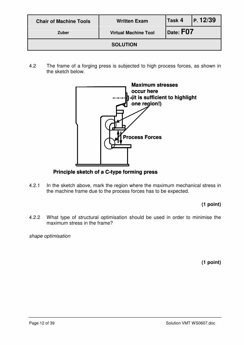
4.2 The frame of a forging press is subjected to high process forces, as shown in the sketch below.
Principle sketch of a C-type forming press
Process Forces
Maximum stresses
occur here
(it is sufficient to highlightone region!)
Principle sketch of a C-type forming press
Process Forces
Maximum stresses
occur here
(it is sufficient to highlightone region!)
4.2.1 In the sketch above, mark the region where the maximum mechanical stress in the machine frame due to the process forces has to be expected.
(1 point)
4.2.2 What type of structural optimisation should be used in order to minimise the maximum stress in the frame?
shape optimisation
(1 point)

Chair of Machine Tools Written Exam Task 4 P. 13/39
Zuber Virtual Machine Tool Date: F07
SOLUTION
Page 13 of 39 Solution VMT WS0607.doc
4.3 The spindle housing of a high-dynamic milling machine is made of fibre-reinforced plastic (FRP)
4.3.1 Name the two components which build up FRP, as used in machine tool design.
Fibres (carbon) and matrix (polymer)
(1 point)
4.3.2 Name two advantages of FRP over conventional engineering materials for machine tool structures.
Choose two from: low density, high stiffness, high strength, material can be “tailored” to load path by aligning the fibre directions
(1 point)
4.3.3 What other materials are usually used for machine tool frames? Name two.
Choose two from: cast iron (grey or spheroidic graphite), polymer concrete, steel
(1 point)

Chair of Machine Tools Written Exam Task 4 P. 14/39
Zuber Virtual Machine Tool Date: F07
SOLUTION
Page 14 of 39 Solution VMT WS0607.doc
4.3.4 Name two possible optimisation parameters that specifically take the material properties of FRP into account!
thickness of each laminate layer, fibre angles
(1 point)
4.4 The optimisation algorithms that are usually used in structural optimisations of machine tool components can be divided into three categories.
4.4.1 Name these three categories.
mathematical programming (MP)
optimality criteria (OC)
genetic or evolutionary strategies (GA or EA)
(1.5 points)
4.4.2 Which of the three algorithms utilises the gradient of the design goal with respect to the optimisation parameters in oder to find an optimal solution?
mathematical programming (MP)
(0.5 point)

Chair of Machine Tools Written Exam Task 4 P. 15/39
Zuber Virtual Machine Tool Date: F07
SOLUTION
Page 15 of 39 Solution VMT WS0607.doc
4.4.3 What is the main advantage of the gradient based approach?
Very fast, needs only a few iterations to find optimum (compared to other algorithms)
(0.5 points)
4.4.4 What is the main disadvantage of the gradient based approach?
very sensitive against local minima!
(0.5 points)

Chair of Machine Tools Written Exam Task 5 P. 16/39
RWTH, University of Aachen Prof. Dr.-Ing. C. Brecher Virtual Machine Tool Date: F07
Responsible Assistant: W. Klein
Page 16 of 39 Solution VMT WS0607.doc
Topic: Requirements on and calculation of guideway systems
Total score : 9,5 Points
5.1 Name two requirements and functions (two for each) of guideway systems in
machine tools (0,25P each). 1P
requirements: functions:
low wear connect relatively moving parts
low friction assure exact movement along one axis
high accuracy take up mass forces
high stiffness take up process loads
low costs
high damping
5.2 Explain how the effects listed below influence the life span and stiffness properties
of guideway systems (fill in: ↑ for increasing lifespan,.↓ for decreasing lifespan, - for
no influence) (0,25P per entry). 1,5P
effect influence on lifespan influence on stiffness
higher preload ↓ ↑
roller guideway instead of ball
guideway (same preload,
same guideway size)
- ↑
wear on carriage and rail
caused by abrasive chips
↓ ↓

Chair of Machine Tools Written Exam Task 5 P. 17/39
RWTH, University of Aachen Prof. Dr.-Ing. C. Brecher Virtual Machine Tool Date: F07
Responsible Assistant: W. Klein
Page 17 of 39 Solution VMT WS0607.doc
5.3 Name two friction sources in rolling contact guideway systems (0,25P each). 0,5P
ball return
ball contact
sealing
5.4 Sketch qualitatively the physical principles of hydrodynamic, hydrostatic and ball
guideway systems and name the main components (0,5 P each). 1,5 P
oil storage tank
slide
hydrodynamicslideway
and plain bearingaerostaticslideway
and plain bearing
air pressuresystem
hydraulicsystem
hydrostaticslideway
and plain bearinglinear ball
guidance systemand ball bearing

Chair of Machine Tools Written Exam Task 5 P. 18/39
RWTH, University of Aachen Prof. Dr.-Ing. C. Brecher Virtual Machine Tool Date: F07
Responsible Assistant: W. Klein
Page 18 of 39 Solution VMT WS0607.doc
5.5 Name three possible calculation objectives (with regards to the guideway system or
the machine) when calculating guideway systems (0,25P each). 0,75P
life span
load bearing capacity
stiffness (machine/ guideway system)
eigenfrequencies (machine)
5.6 Name three effects that cause guideway failure (0,25P each). 0,75P
overload
chips in the rolling elements‘ chains
wear of rolling elements and rail
low/no lubrication
5.7 Given is the displacement curve for a rolling contact guideway system (see figure).
Calculate the compression, tension and side stiffnesses at 40 kN load for a
guideway system of the sizes 45 and 65 each. Use the curves given below! 1,5P

Chair of Machine Tools Written Exam Task 5 P. 19/39
RWTH, University of Aachen Prof. Dr.-Ing. C. Brecher Virtual Machine Tool Date: F07
Responsible Assistant: W. Klein
Page 19 of 39 Solution VMT WS0607.doc
tension load
compression load
side load
c45, tension= 40000 N/26 µm=1538 N/µm (+- 154 N/µm)
c65, tension= 40000 N/9 µm=4444 N/µm (+- 444 N/µm)
selection of displacements:
(+-10% dev.) 0,125P each (0,75P)
calculation of stiffness values:
(+-10% dev.) 0,125P each (0,75P)
c45, compression= 40000 N/17 µm=2353 N/µm (+- 235 N/µm)
c65, compression= 40000 N/9 µm=4444 N/µm (+- 444 N/µm)
c45, side= 40000 N/42 µm=952 N/µm (+- 95 N/µm)
c65, side= 40000 N/27 µm=1481 N/µm (+- 148 N/µm)

Chair of Machine Tools Written Exam Task 5 P. 20/39
RWTH, University of Aachen Prof. Dr.-Ing. C. Brecher Virtual Machine Tool Date: F07
Responsible Assistant: W. Klein
Page 20 of 39 Solution VMT WS0607.doc
5.8 Given is a compliant machine tool column based on a guideway system (two
carriages per rail, see figure). The column has a weight of 1500 kg. Additionally, the
column is loaded with a vertical force of 40000 N in the middle axis of the column
(point P) so that all carriages are loaded equally. (gravity coefficent g=9.81 m/s²,
assume that each carriage takes the same amount of the gravity force!)
5.8.1 Using the stiffness value of exercise no. 7, calculate the overall
compression stiffnesses kcombined, 45 and kcombined, 65 of the column‘s
guideway system consisting of 4 carriages (assume kcarriage 45=2000 N/µm
and kcarriage 65=4000 N/µm in case of failing task 7!). 0,5 P
parallel springs: kcombined, 45= 4 * k45, compression= 4 * 2353 N/µm= 9412 N/µm
kcombined,65= 4 * k65, compression= 4 * 4444 N/µm= 17776 N/µm
(failed task 7:
kcombined, 45= 4 * k45, compression= 4 * 2000 N/µm= 8000 N/µm
kcombined,65= 4 * k65, compression= 4 * 4000 N/µm= 16000 N/µm)
(calculation: 0,25 P each)
x
y
F=40000 N
k carriage 45, 65
k column P
z

Chair of Machine Tools Written Exam Task 5 P. 21/39
RWTH, University of Aachen Prof. Dr.-Ing. C. Brecher Virtual Machine Tool Date: F07
Responsible Assistant: W. Klein
Page 21 of 39 Solution VMT WS0607.doc
5.8.2 The column’s stiffness is given in three coordinate directions with respect to
point P:
,
,
,
60
60 /
2500
column x
column y
column z
k
k N µm
k
=
From the diagram in task 7 choose the minimum sized guideway system so that
the column’s overall compression displacement (column plus guideway system)
on point P is lower or equal than 27 µm (Assume that the gravity force and the
load F both act in point P! Pay respect to progressive stiffness curves in the
diagram!). 1,5 P
Displacement of point P at 54715 N: 21,9 µm (kcolumn, z)
Load per carriage: 54715 N/4=13678,8 N, allowable displacement: 5,1µm
Diagram ‚compression‘: check displacements at 13678,8 N (<5,1 µm)
� Minimum sized guideway system: 45
(displacement of column: 0,5 P,
calculated load per carriage 0,5P,
right selection of guideway system 0,5P)

Chair of Machine Tools Written Exam Task 5 P. 22/39
Türker Yagmur Virtual Machine Tool Date: F07
SOLUTION
Page 22 of 39 Solution VMT WS0607.doc
Topic: Bearings, Main spindles
Total score : 10,0 Points
5.1 In machine tools, different principles of guideways and bearings are used. Figure 1 shows 3 principles of guideways and bearings.
.
Figure 1: Different types of guideways and bearings
5.1.1 Name the principles of the shown guideways and bearings.
3*0.25 points = 0.75 points
5.1.2 Figure 2 illustrates a electromagnetic bearing. Name the different components.
Aerostatic bearing/guideway
Roller bearing/guideway
Hydrostatic bearing/guideway

Chair of Machine Tools Written Exam Task 5 P. 23/39
Türker Yagmur Virtual Machine Tool Date: F07
SOLUTION
Page 23 of 39 Solution VMT WS0607.doc
Figure 2: Electromagnetic bearing
5.1.3 Explain shortly, why the electromagnetic bearing is suitable for highest rotational speeds. Name also 2 advantages and 2 disadvantages of this principle.
Explanation:
The electromagnetic bearing comprises of non touching parts. Therefore, it has almost no friction torque and a lubrication is not required. (0.5 points)
Advantages:
- active machine elements
- low friction torques
Disadvantages:
- low maximum loads
- expensive periphery needed
Touch down bearing
Radial bearing
Axial bearing
Position sensor
4*0.25 points = 1 point

Chair of Machine Tools Written Exam Task 5 P. 24/39
Türker Yagmur Virtual Machine Tool Date: F07
SOLUTION
Page 24 of 39 Solution VMT WS0607.doc
- heat losses in the coil
4*0.25 points = 1 point
5.2 The different types of roller bearings differ in their properties. Therefore, it is not possible to use all types for all tasks.
5.2.1 Name two roller bearing types which are suitable to realize high rotational speeds. Explain why these types are suitable for high rotational speeds.
Bearing types:
Angular contact ball bearing (spindle bearing),
Deep groove ball bearing,
2*0.25 points = 0.5 points
Explanation:
The called bearings consist of balls as sliding bodies. The small contact surface (point contact) provides a low friction between ball and inner/outer ring. Furthermore, a favourable lubrication can be realized with ball bearings. (0.5 points).
5.2.2 Associate relative to each other the different bearing types according to their properties respective the characteristics radial load accomondation and low
friction. Use for the classification „good“, „middle“, „bad“ the symbols „+“, „o“, „-“. Use following table.
Bearing type: Rad. load accomondation
Low friction
Angular contact ball bearing - +
Taper roller bearing o o
Double row cylindrical roller bearing + -

Chair of Machine Tools Written Exam Task 5 P. 25/39
Türker Yagmur Virtual Machine Tool Date: F07
SOLUTION
Page 25 of 39 Solution VMT WS0607.doc
6*0.25 points = 1.5 points
5.3 Sketch a rigid-moveable bearing system with following characteristics: - At the rigid bearing side use a tandem back to back arrangement consisting of angular contact ball bearings.
- At the movable bearing side use a face to face arrangement consisting of angular contact ball bearings.
Hint: Sketch in the functional surfaces of the housing, i.e. the bearing seats. Consider how the moveable bearing is preloaded. Draw the pressure angles of the bearings and name the kind of arrangement (back to back (“O”) or face to face (“X”)). Make sure that the bearing rings are mounted in defined position on the spindle and in the housing. Be sure that the spindle cannot be pulled out of the housing!! Name all used components!
Use the following sketch as a help.
cover: 0.25 P
rigid bearing seat: 0.25 P flange
tandem back to back
arrangement: 0.5 P
face to face arrangement with
the correct preload: 0.5 P
lock nut: 0.25 P
correct pressure angles:
- rigid bearings: 0.25 P
- movable bearings: 0.25 P
moveable seat: 0.25 P
nut: 0.25 P
total: 3 P
sleeve: 0.25 P
cover: 0.25 P
rigid bearing seat: 0.25 P flange
tandem back to back
arrangement: 0.5 P
face to face arrangement with
the correct preload: 0.5 P
lock nut: 0.25 P
correct pressure angles:
- rigid bearings: 0.25 P
- movable bearings: 0.25 P
moveable seat: 0.25 P
nut: 0.25 P
total: 3 P
sleeve: 0.25 P

Chair of Machine Tools Written Exam Task 5 P. 26/39
Türker Yagmur Virtual Machine Tool Date: F07
SOLUTION
Page 26 of 39 Solution VMT WS0607.doc
5.4 During the formulation of the dynamic behaviour of a spindle-bearing-system, a linear differential equation system is developed with the prerequisite of smaller oscillation amplitudes.
5.4.1 Write down the inhomogeneous linear differential equation system for a non-damped system and name all matrices and vectors.
inhomogenious linear differential equaltion for a non-damped system:
(0.5 points)
Mass matrix
Acceleration vector
Stiffness matrix
Displacement vector
Force vector
5*0.25 points = 1.25 points
[ ] { } [ ] { } { }FuKuM =⋅+⋅ &&

Chair of Machine Tools Written Exam Task ? P. 27/39
Gero Gerlach Virtual Machine Tool Date: F07
SOLUTION
Page 27 of 39 Solution VMT WS0607.doc
Mechanical Feed Drive Components
Total score : 8.25 Points
The structure of a feed axis essentially contains an electric servomotor and the
mechanical transfer elements. All components in the force-flux between motor and tool
respectively workpiece are considered as feed drive components.
7.1.1 Please name two essential tasks of feed drives in machine tools. (0.5 P)
- Generation of relative motion between workpiece and tool for cutting process 0.25 P
- Generation of feed force and feed rate 0.25 P
7.1.2 Please enumerate 4 requirements on feed drives. (1.0 P)
- zero backlash, 0.25 P
- low friction, 0.25 P
- high acceleration capability, 0.25 P
- high stiffness, 0.25 P
- high geometric & kinematic accuracy of feed drive components 0.25 P

Chair of Machine Tools Written Exam Task ? P. 28/39
Gero Gerlach Virtual Machine Tool Date: F07
SOLUTION
Page 28 of 39 Solution VMT WS0607.doc
7.2 A machine slide (S) carrying a workpiece (W) has to be driven by a feed drive consisting of a servo motor (M), a gear (G) and a rack-pinion-system (R/P).
M
m w
m s
Getriebe
J M , n Mn , n Mmax
Motor
Werkstück
Schlitten
Ritzel- Zahnstange
i G ,
,J GL
J GM
r R , J R
Führungen
r GLR
Figure 7.1: Structure of a rack-pinion-axis
The following data is available for the feed drive design:
Slide mass (including rack): mS = 400 kg
Workpiece mass: mW = 250 kg
Pinion wheel radius: rP = 50 mm
Pinion mass moment of inertia: JP = 0,019 kgm2
Motor mass moment of inertia: JM = 0,095 kgm2
Mass moment of inertia motor sided gear : JGM = 0,00003 kgm2
Mass moment of inertia load sided gear: JGL = 0,0005 kgm2
Gear wheel radius load sided rGL = 100 mm
Nominal motor speed: nMn = 600 min-1
Maximum motor speed: nMmax = 1400 min-1
motor gear rack-pinion-system
rP, JP
guidance
slide/ table
workpiece

Chair of Machine Tools Written Exam Task ? P. 29/39
Gero Gerlach Virtual Machine Tool Date: F07
SOLUTION
Page 29 of 39 Solution VMT WS0607.doc
7.2.1 Please calculate the required gear ratio if a rapid table speed of vmax = vrts = 25 m/min is needed! (2.0 P)
Gear ratio: maxP
maxM
driven
driveup
n
n
n
ni == 0.5 P
Pinion speed: P
rtsP
r2
vn
⋅π= 0.5 P
Result: rts
maxMP
P
rts
maxM
maxP
maxMup
v
nr2
r2
v
n
n
ni
⋅⋅π=
⋅π
== 0.5 P
59,17minm25
min1400m05,02
minm25
min1400mm502i
1
1
1
1
up =⋅
⋅⋅π=
⋅
⋅⋅π=
−
−
−
−
0.5 P
7.2.2 Please choose a whole-numbered gear ratio to ensure the required rapid table speed. (0.75 P)
maxP
maxM
driven
driveupG
n
n
n
nii ==< => 59,1717iG <= 0.75 P
7.2.3 Please evaluate the total mass moment of inertia JRpd,tot reduced to the motor shaft! (2.5 P)
red,W,Sred,Pred,GLGMMtot,Rpd JJJJJJ ++++= 0.5 P
GL2
G
red,GL Ji
1J ⋅= 0.25 P
22
2red,GL kgm00000173,0kgm0005,017
1J =⋅= 0.25 P
22
2P2
G
red,P kgm0000657,0kgm019,017
1J
i
1J =⋅=⋅= 0.25 P
2
PWS2G
red,W,S r)mm(i
1J ⋅+⋅= 0.25 P
22
2
22
2red,W,S kgm0056228,0kgm625,117
1m05,0)kg250kg400(
17
1J =⋅=⋅+⋅=
0.5 P

Chair of Machine Tools Written Exam Task ? P. 30/39
Gero Gerlach Virtual Machine Tool Date: F07
SOLUTION
Page 30 of 39 Solution VMT WS0607.doc
Result:
2
2tot,Rpd
kgm10072377,0
kgm)0056228,00000657,000000173,000003,0095,0(J
=
++++=
7.2.4 Please explain shortly the design possibilities to avoid backlash in rack-pinion-drives by a sketch and a description (Name the components). (0.75 P each) (1.5 P)
a) Double helical pinion, preloaded by spring force. (0.75 P)
The backlash is eliminated by the fact that two helical gear pinions comb with a toothed rack. The lower pinion is moved axially through elastic force on a spline shaft step. Through this, both pinions contact the opposite side of the toothed rack.

Chair of Machine Tools Written Exam Task ? P. 31/39
Gero Gerlach Virtual Machine Tool Date: F07
SOLUTION
Page 31 of 39 Solution VMT WS0607.doc
b) Electrical preloading of two separate pinions: (0.75 P)
Electrically preloaded dual-pinion drives utilize two motors, each driving one pinion, which are loaded against each other by means of a special motor controller. The realised motor torque M is provided by the motor torques M1, M2. The single torque characteristic are staggered against each other to compensate the backlash of the drive-system. One pinion is considered the driving pinion, while the other is braking. During deceleration, the braking motor takes over control of the axis and the drive motor switches to preloading.

Chair of Machine Tools Written Exam Task 7 P. 32/39
Andreas Schmidt Virtual Machine Tool Date: F07
SOLUTION
Page 32 of 39 Solution VMT WS0607.doc
Simulation of Feed Drives
Total score : 11,0 Points
8.1 Rotary electrical motors are the usual choice as drives in a machine tool.
8.1.1 Name two of the three physical laws on which the functional principles of all electrical motors are based and describe their meanings in one sentence each.
Ampere’s law: The creation of a magnetic field via a current-carrying conductor.
Faraday’s law of induction: Induction of voltage in a coil via movement in a homogeneous magnetic field. When the electric circuit is closed, current flows in the coil. Alternatively to the movement, the strength of the magnetic field may vary.
Lorentz force law: A (Lorentz) force affects a current-carrying conductor in a magnetic field. Torque is produced by force couples on current-carrying pairs of conductors in the magnetic field or by direct, magnetic forces.
4 * 0,25 Points = 1,0 Points
8.1.2 Describe in 2-3 sentences the basic functional principle of a separately excited DC motor.
DC-excited coils in the stator generate a constant magnetic field (0,25). The armature coil in the rotor is also fed with DC current (0,25). The current-carrying conductors in the stator field experience (Lorentz-)forces, which result in a torque (0,25). The armature current is passed through graphite brushes (0,25) and a mechanical commutator (0,25), which changes the direction of current in the armature coils in a manner that keeps it constant under the stator poles (0,25). With increasing speed a growing counter voltage is induced into the armature circuit, which counteracts the armature voltage (0,25).
7 * 0,25 = 1,75 Points
8.1.3 Describe the idling speed n0 of the DC motor as a function of the armature voltage and the excitation.
Idling: T = 0 ⇒ IA = 0 ⇒ Φ⋅
=1
A0
k
Un
0,5 Points

Chair of Machine Tools Written Exam Task 7 P. 33/39
Andreas Schmidt Virtual Machine Tool Date: F07
SOLUTION
Page 33 of 39 Solution VMT WS0607.doc
8.1.4 Describe the starting torque Tstart of the DC motor as a function of the armature voltage and the excitation.
Starting: n = 0 ⇒ Ui = 0 ⇒ 1 Astart
A
k UT
2 R= ⋅Φ ⋅
π
0,75 Points
8.2. The feedback control loop for the feed axes normally comprises “position control loop”, “velocity (rotational speed) control loop” and also “current control loop”.
8.2.1 Briefly discuss the reasons of employment of the three feedback loops.
Position control loop is to compare the actual position value with the reference position value. The difference between these two values (error signal) will be controlled (compensated, eliminated) in the position controller. Thus, the position controller is fairly important for the feed axes control to maintain the required positioning accuracy.
Velocity (rotational speed) control loop enhances the damping characteristic of the system. This means, this control loop enables the system to achieve the higher system dynamics.
Current control loop is normally enclosed in the feed (drive) amplifier and has the fastest cycle time (working frequency). The cycle time of this controller is generally under 250 sµ (= 4kHz). Main tasks of this control loop are to control
the acceleration of motors and to enhance the dynamic behaviour of the entire control system.
3*0,5 Points= 1,5 Points
8.2.2 What is the difference between open loop control and closed loop control?
open loop: calculation of output after one-time input, no feedback or adjustment, needs fixed, reliable system
closed loop: feedback of output towards the input, continuous comparison and control of the resulting error to reach target value exactly. Better against disturbances
2 * 0,5 Points = 1,0 Points

Chair of Machine Tools Written Exam Task 7 P. 34/39
Andreas Schmidt Virtual Machine Tool Date: F07
SOLUTION
Page 34 of 39 Solution VMT WS0607.doc
8.3 Calculate the transfer function of the following block diagram.
+-
xinput xoutput
G1
G5
G2
G4G3
G6
+
Figure 3:block diagram of a fictitious control technical system
( )( )654
4321
input
output
GGG1
GGGG
x
x
+⋅−
⋅⋅−=
(3 different rules to concatenate subsystems have to be used)
3*0,25 + 0,75 = 1,5 Points
8.4 A PT2-System has three characteristic parameters, the gain constant K, the damping ratio D and the characteristic frequency ωn.
8.4.1 Which effects on the system behaviour do they have?
K controls the system´s amplification from input to output.
The Damping factor indicates the system’s tendency to oscillate.
The characteristic frequency ωn is the oscillation frequency of a system after an impulse excitation (without damping). (Alternative explanation: A forced excitation that matches the characteristic frequency leads to a resonance effect)
3*0.5 = 1.5 points

Chair of Machine Tools Written Exam Task 7 P. 35/39
Andreas Schmidt Virtual Machine Tool Date: F07
SOLUTION
Page 35 of 39 Solution VMT WS0607.doc
8.4.2 Give the standard transfer function of a PT2-System and explain the following range of damping values: D = 0, 0 < D < 1, D = 1, D > 1.
( )2
nn
2
2
nPT
sD2s
KsG
2 ω+⋅ω⋅⋅+ω⋅
=
D = 0: Steady oscillation with the characteristic frequency ωn.
0 < D < 1: Step response of the system converges onto the gain constant K
(y∞ = K).
D = 1: Step response of the system converges onto the gain constant K without oscillation.
D > 1: Step response converges exponentially onto the gain constant K.
transfer function 0.5, range of damping values 4 * 0.25 = 1.5 Points

Chair of Machine Tools Written Exam Task 7 P. 36/39
Andreas Schmidt Virtual Machine Tool Date: F07
SOLUTION
Page 36 of 39 Solution VMT WS0607.doc
Multi-Body Simulation
Total score : 9,5 Points
9.1 The Multi-Body-Simulation (MBS) with rigid bodies is able to compute the behaviour of mechanical systems with large motion amplitudes.
9.1.1 A multi-body simulation software usually offers kinematic, dynamic, static and inverse dynamic analysis. Please discribe the inverse-dynamic analysis. How is this type of analysis related to other types? What is defined as input and what is the output of this simulation?
Hybrid form of the dynamic- and kinematic-analysis. The motion of one or several bodies of the mechanical system is defined and is leading to a complete determination of the position, the velocity and the acceleration of the system. Afterward the algebraic equations of motion are solved by the use of the known positions, velocities and accelerations to determine the forces which cause these motions.
3 * 0,5 Punkte = 1,5 Punkte
9.1.2 There are two general types of connecting elements in the MBS, that can be used to assemble single bodies into a multi-body system. Please give the name of both element types and characterize the type of mathematical equation that result from the element definition
Kinematic joints – algebraic non-linear equations
Force elements (Spring-Damper, etc) – differential equations
4 * 0,25 Punkte = 1,0 Punkte
9.1.3 The figure shows the schematic assembly of a feed drive for machine tools with electric-servo-motor and a ballscrew-nut-system. Please give the missing names of the joint types, that are used to build a kinematic model of the drive system. The two linear guides are modelled with one constraint. Give the number of kinematic degrees of freedom.

Chair of Machine Tools Written Exam Task 7 P. 37/39
Andreas Schmidt Virtual Machine Tool Date: F07
SOLUTION
Page 37 of 39 Solution VMT WS0607.doc
motor
table
linear guide
transmissiongearing
synchronous belt drive
fixed bearingball screw spindle
spindle nut -rail-shoe
machine bed
motor
table
linear guide
transmissiongearing
synchronous belt drive
fixed bearingball screw spindle
spindle nut -rail-shoe
machine bed
x
y
z
x
y
z
Figure 1 Feed drive with ballscrew-nut system
Fixed bearing between machine bed and spindle revolute joint (1DOF)
Spindle nut between spindle and table screw joint (1DOF)
Linear guide between table and machine bed translational joint (1DOF)
4 * 0,25 Punkte = 1,0 Punkte
9.1.4 Please give the kinematic constraint equations for the joints in the feed drive system. Remember that a screw is described by the pitch h. If there is no constraint equation for a specific direction mark it as a function of time f(t).
Fixed bearing
=
ϕ∆
ϕ∆
ϕ∆
∆
∆
∆
0
0
)t(f
0
0
0
z
y
x
z
y
x
Linear guide
=
ϕ∆
ϕ∆
ϕ∆
∆
∆
∆
0
0
0
0
0
)t(f
z
y
x
z
y
x

Chair of Machine Tools Written Exam Task 7 P. 38/39
Andreas Schmidt Virtual Machine Tool Date: F07
SOLUTION
Page 38 of 39 Solution VMT WS0607.doc
Spindle nut
π⋅ϕ∆
=
ϕ∆
ϕ∆
ϕ∆
∆
∆
∆
0
0
)t(f
0
0
2/h
z
y
x x
z
y
x
Example: Ball joint
=
ϕ∆
ϕ∆
ϕ∆
∆
∆
∆
)t(f
)t(f
)t(f
0
0
0
z
y
x
z
y
x
3 * 0,5 Punkte = 1,5 Punkte
9.2 Multi-Body-Simulations can be performed both with rigid and flexible bodies.
9.2.1 In which case is the use of flexible bodies necessary? State two effects onto the simulation results, if rigid instead of flexible bodies are used?
The use of flexible bodies is necessary if deformation of individual machine parts have significant impact onto the machine tool’s dynamic behaviour. Otherwise, neither the eigen-frequencies nor the weak points of the structure can be determined correctly.
0,5 points + 2 times 0,25 points --> 0,5 points
9.2.2 If you have to compute the dynamic behaviour of the system shown in Figure 1, it can be calculated with Finite-Element-Software Packages or with Multi-Body-Simulation. State in which domains, time- or frequency domain, each simulation is running in?
Multi-Body-Simulation: Time domain; FE-Simulation: Frequency domain. 2 times 0,25 points --> 0,5 points
9.2.3 The static and dynamic flexible properties of the table in Figure 1 should be incorportated in the multi-body-computation. Therefor a Finite-Element model of the table was built up. Which computations have to be performed for the integration of flexible bodies into the multi-body-simulation model?
1.) Normal mode computation with constraints on each degree of freedom that transfers forces in the multi-body-simulation-modell.

Chair of Machine Tools Written Exam Task 7 P. 39/39
Andreas Schmidt Virtual Machine Tool Date: F07
SOLUTION
Page 39 of 39 Solution VMT WS0607.doc
2.) Calculation of static correction modes
2 x 0,5 points ���� 1,0 points
9.2.4 With the use of flexible bodies in MBS, more realistic results with respect to the dynamic behaviour and calculated mode shapes can be achieved. In this context the MAC-value is often of interest. For what stands the acronym MAC? For what is the MAC-value used? Which meaning do high values of the MAC-value have?
1.) MAC : Modal Assurance Criterion
2.) The MAC-value is used to compare measured and calculates mode shapes
3.) High MAC-values mean a high level of consistency between measured and simulated mode shapes.
3 x 0,5 points ���� 1,5 points
9.2.5 Nowadays more and more machine tools use linear direct drives as feed drive systems. What is the problem when modelling these kind of feed drives compared to normal ball screw drives? Explain how this problem can be treated by the Multi-Body-Simulation?
Linear direct drives do not have mechanical stiffness properties like mechanical components like e.g. ball screw drives. Linear direct drives’ stiffness and damping is determined solely by the drive’s feedback control system. The simulation of this control system can only be performed in the Computer Aided Control Engineering (CACE) environment (MATLAB/Simulink) with the simulation of the control loop.
2 times 0,5 points --> 1,0 points