solenoid/pneumatic valves, iso 5599−1 - zycon 4 manual override tool ahb 2 / 1.2−99 5...
TRANSCRIPT

2003/10 – Subject to change – Products 2004/2005 2 / 1.2−1
�Electrically or pneumatically
actuated valves
�With internal or external pilot
air
�Pneumatic or mechanical reset
Specified types in accordance with
ATEX directive for potentially
explosive atmospheres
� www.festo.com/en/ex
Sta
ndar
d di
rect
iona
l con
trol
val
ves
ISO
55
99
/1
1.2
Solenoid/pneumatic valves, ISO 5599−1

Products 2004/2005 – Subject to change – 2005/042 / 1.2−2
Solenoid valves, ISO 5599−1Product range overview
Function Version Type ISO size Nominal flow Pneumatic working Operating voltageyp
rate
g
port on sub−base
[l/min]
p
[V DC] [V AC]
5/2−way valves, Solenoid valve/ y ,
single solenoid MN1H 1 1,200 G¼ 24 110, 230g
2 2,300 Gy
, 3
3 4,500 G½
MFH 1 1,200 G¼ 12, 24, 42, 48 24, 42, 48,
2 2,300 Gy
, , , , , ,
110, 230, 240
3 4,500 G½
, ,
MDH 4 6,000 G¾ 24 42, 110, 230, , 3
Solenoid valve with central plug M12x1
MEBH−Ī−ZSR 1 1,200 G¼ 24 –
2 2,300 Gy
3 4,500 G½
Solenoid valve with single plug M12x1, connector pin allocation to VDMA or Desina
MDH 1 1,200 G¼ 24 –
2 2,300 Gy
3 4,500 G½
5/2−way valves, Double solenoid valve/ y ,
double solenoid JMN1H 1 1,200 G¼ 24 110, 230
2 2,300 Gy
, 3
3 4,500 G½
Double solenoid valve with dominant signal at 14
JMN1DH 1 1,200 G¼ 24 110, 230J
2 2,300 Gy
, 3
3 4,500 G½
Double solenoid valve
JMFH 1 1,200 G¼ 12, 24, 42, 48 24, 42, 48,
2 2,300 Gy
, , , , , ,
110, 230, 240
3 4,500 G½
, ,
Double solenoid valve with dominant signal
JMFDH 1 1,200 G¼ 12, 24, 42, 48 24, 42, 48,J
2 2,300 Gy
, , , , , ,
110, 230, 240
3 4,500 G½
, ,
Double solenoid valve
JMDH 4 6,000 G¾ 24 42, 110, 230, , 3
Sta
ndar
d di
rect
iona
l con
trol
val
ves
ISO
55
99
/1
1.2

2005/04 – Subject to change – Products 2004/2005 2 / 1.2−3
Solenoid valves, ISO 5599−1Product range overview
Type Pilot air supply Type of reset � Page
internal external pneumatic mechanicalp
spring spring
Solenoid valve
MN1H � � � � 2 / 1.2−18
� � � �
/
� � � �
MFH � � � � 2 / 1.2−30
� � � �
/ 3
� � � �
MDH 2 / 1.2−65
� – � –
/ 5
Solenoid valve with central plug M12x1
MEBH−Ī−ZSR � – � � 2 / 1.2−41
� – � �
/
� – � �
Solenoid valve with single plug M12x1, connector pin allocation to VDMA or Desina
MDH � � � � 2 / 1.2−30
� – � �
/ 3
� – � �
Double solenoid valve
JMN1H � � – – 2 / 1.2−22J
� � – –
/
� � – –
Double solenoid valve with dominant signal at 14
JMN1DH � � – – 2 / 1.2−22J
� � – –
/
� � – –
Double solenoid valve
JMFH � � – – 2 / 1.2−34J
� � – –
/ 3
� � – –
Double solenoid valve with dominant signal at 14
JMFDH � – – – 2 / 1.2−34J
� – – –
/ 3
� – – –
Double solenoid valve
JMDH � – – – 2 / 1.2−68J
� – – –
/
� – – –
Sta
ndar
d di
rect
iona
l con
trol
val
ves
ISO
55
99
/1
1.2

Products 2004/2005 – Subject to change – 2005/042 / 1.2−4
Solenoid valves, ISO 5599−1Product range overview
Function Version Type ISO size Nominal flow Pneumatic working Operating voltageyp
rate
g
port on sub−base
p g g
[l/min]
p
[V DC] [V AC]
5/2−way valves, Double solenoid valve with central plug M12x1/ y ,
double solenoid JMEBH 1 1,200 G¼ 24 V DC –J
2 2,300 Gy
3 4,500 G½
Double solenoid valve with central plug M12x1, dominant signal at 14
JMEBDH 1 1,200 G¼ 24 V DC –J
2 2,300 Gy
3 4,500 G½
Double solenoid valve with single plug M12x1, connector pin allocation to VDMA or Desina
JMDH 1 1,200 G¼ 24 V DC –J
2 2,300 Gy
3 4,500 G½
Double solenoid valve with single plug M12x1, connector pin allocation to VDMA or Desina, dominant signal at 14
JMDDH 1 1,200 G¼ 24 V DC –J
2 2,300 Gy
3 4,000 G½
Function Version Type ISO size Nominal flow Pneumatic working Operating voltage
rate
g
port on sub−base
[l/min]
p
[V DC] [V AC]
5/3−way valves Solenoid valve/3 y
MN1H−5/3Ī 1 1,200 G¼ 24 110, 230
2 2,300 Gy
, 3
3 4,100 G½
MFH−5/3Ī 1 1,200 G¼ 12, 24, 42, 48 24, 42, 48,
2 2,300 Gy
, , , , , ,
110, 230, 240
3 4,100 G½
, ,
MDH 5/3 4 6 000 G¾ 24 110 230MDH−5/3Ī 4 6,000 G¾ 24 110, 230MDH−5/3Ī 4 6,000 G¾ 24 110, 230
Solenoid valve with central plug M12x1
MEBH−5/3−Ī−Ī−ZSR 1 1,200 G¼ 24 –/3
2 2,300 Gy
3 4,100 G½
Solenoid valve with single plug M12x1, connector pin allocation to VDMA or Desina
MDH−5/3Ī 1 1,200 G¼ 24 –/3
2 2,300 Gy
3 4,000 Ī4,600 G½
Sta
ndar
d di
rect
iona
l con
trol
val
ves
ISO
55
99
/1
1.2

2005/04 – Subject to change – Products 2004/2005 2 / 1.2−5
Solenoid valves, ISO 5599−1Product range overview
Type Pilot air supply Type of reset � Pageyp
internal external pneumatic spring mechanical spring
g
Double solenoid valve with central plug M12x1
JMEBH � – – – 2 / 1.2−45J
� – – –
/ 5
� – – –
Double solenoid valve with central plug M12x1, with dominant signal
JMEBDH � – – – 2 / 1.2−45J
� – – –
/ 5
� – – –
Double solenoid valve with single plug M12x1, connector pin allocation to VDMA or Desina
JMDH � – – – 2 / 1.2−34J
� – – –
/ 3
� – – –
Double solenoid valve with single plug M12x1, connector pin allocation to VDMA or Desina, dominant signal at 14
JMDDH � – – – 2 / 1.2−34J
� – – –
/ 3
� – – –
Type Pilot air supply Mid position � Page
internal external closed exhausting pressurisedg
Solenoid valve
MN1H−5/3Ī � � � � � 2 / 1.2−26/3
� � � � �
/
� � � � �
MFH−5/3Ī � � � � � 2 / 1.2−37/3
� � � � �
/ 37
� � � � �
MDH−5/3Ī � – � � – 2 / 1.2−71/3
Solenoid valve with central plug M12x1
MEBH−5/3−Ī−Ī−ZSR � – � � � 2 / 1.2−49/3
� – � � �
/ 9
� – � � �
Solenoid valve with single plug M12x1, connector pin allocation to VDMA or Desina
MDH−5/3Ī � – � � � 2 / 1.2−37/3
� – � � �
/ 37
� – � � �
Sta
ndar
d di
rect
iona
l con
trol
val
ves
ISO
55
99
/1
1.2
Products 2004/2005 – Subject to change – 2005/042 / 1.2−6
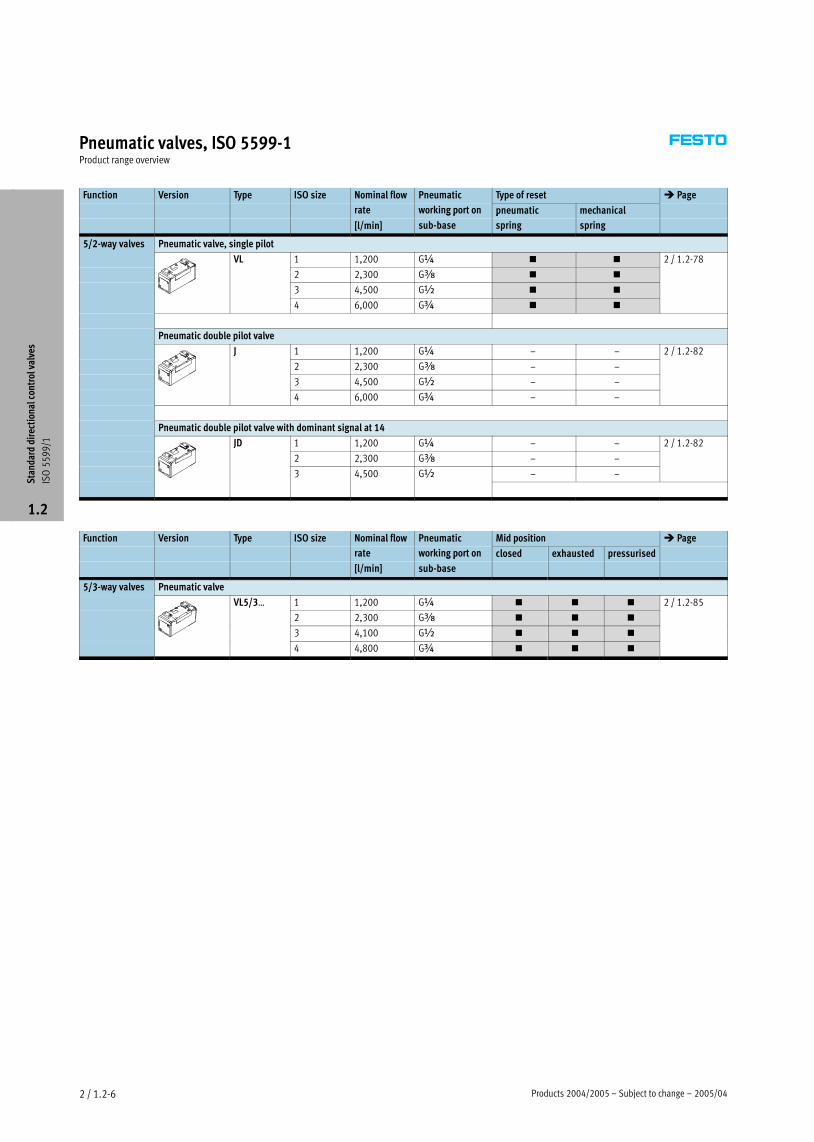
Pneumatic valves, ISO 5599−1Product range overview
Function Version Type ISO size Nominal flow Pneumatic Type of reset � Page
rate working port on pneumatic mechanical
[l/min]
g p
sub−base
p
spring spring
5/2−way valves Pneumatic valve, single pilot/ y
VL 1 1,200 G¼ � � 2 / 1.2−78
2 2,300 Gy � �
/ 7
3 4,500 G½ � �
4 6,000 G¾ � �
Pneumatic double pilot valve
J 1 1,200 G¼ – – 2 / 1.2−82
2 2,300 Gy – –
3 4,500 G½ – –
4 6,000 G¾ – –
Pneumatic double pilot valve with dominant signal at 14
JD 1 1,200 G¼ – – 2 / 1.2−82
2 2,300 Gy – –
3 4,500 G½ – –
Function Version Type ISO size Nominal flow Pneumatic Mid position � Page
rate working port on closed exhausted pressurised
[l/min]
g p
sub−base
5/3−way valves Pneumatic valve/3 y
VL5/3Ī 1 1,200 G¼ � � � 2 / 1.2−85/3
2 2,300 Gy � � �
/ 5
3 4,100 G½ � � �
4 4,800 G¾ � � �
Sta
ndar
d di
rect
iona
l con
trol
val
ves
ISO
55
99
/1
1.2

2005/04 – Subject to change – Products 2004/2005 2 / 1.2−7
Solenoid valves, ISO 5599−1Type codes for valves with square plug
MN1H � 5/3 G � D−1 � � � � C �
Type
MN1H Single pilot, for N1 solenoid coil
MFH Single solenoid, for F solenoid coil
MDH Single solenoid, with D solenoid coil
MEBH Single solenoid, with EB solenoid coil
JMN1H Double solenoid, for N1 solenoid coil
JMN1DH Double solenoid, for N1 solenoid coil,
with dominant signal at 14
JMFH Double solenoid, for F solenoid coil
JMFDH Double solenoid, for F solenoid coil,
with dominant signal at 14
JMDH Double solenoid, with D solenoid coil
Valve function
5/2 5/2−way valve
5/3 5/3−way valve
Mid position
G closed
E exhausted
B pressurised
Size
D−1 ISO size 1
D−2 ISO size 2
D−3 ISO size 3
¾−D−4 ISO size 4
Electrical connection, operating voltage
Plug, square design to DIN EN 175301−803, type A
24DC 24 V DC
Pilot air supply
internal
S external
Type of reset
FR Mechanical spring
Pneumatic spring
Generation
C Series C
CT Free of copper and PTFE
Sta
ndar
d di
rect
iona
l con
trol
val
ves
ISO
55
99
/1
1.2

Products 2004/2005 – Subject to change – 2005/042 / 1.2−8
Solenoid valves, ISO 5599−1Type codes for valves with round plug
MDH � 5/3 G � D−1 � � � � C �
Type
MDH Single solenoid, with D solenoid coil
MEBH Single solenoid, with EB solenoid coil
JMDH Double solenoid, for D solenoid coil
JMDDH Double solenoid, for D solenoid coil,
with dominant signal at 14
JMEBH Double solenoid, with EB solenoid coil
JMEBDH Double solenoid, with EB solenoid coil,
with dominant signal at 14
Valve function
5/2 5/2−way valve
5/3 5/3−way valve
Mid position
G closed
E exhausted
B pressurised
Size
D−1 ISO size 1
D−2 ISO size 2
D−3 ISO size 3
Electrical connection, operating voltage
Central plug, round design, M12x1
ZSR 24 V DC
Individual plug, round design, M12x1
M12 24 V DC
Pin allocation
2−pin to VDMA
D 4−pin to Desina
Pilot air supply
internal
S external
Type of reset
FR Mechanical spring
Pneumatic spring
Generation
C Series C
Sta
ndar
d di
rect
iona
l con
trol
val
ves
ISO
55
99
/1
1.2

2005/04 – Subject to change – Products 2004/2005 2 / 1.2−9
Solenoid valves, ISO 5599−1Peripherals overview
Port pattern on sub−base to ISO 5599−1
Defined interfaces between valve and sub−base
ISO 1 ISO 2 ISO 3 ISO 4
aD
5
4
1
2
3
aB
Sub−base port designations
Solenoid valves Pneumatic valves
aD Control section External pilot air supply for pilot valve 14 Signal input 14
www.festo.com
5 Power section Valve exhaust port 5
4 Power section Working port 4
www.festo.com
1 Power section Working air supply port 1
2 Power section Working port 2
3 Power section Valve exhaust port 3
aB Control section External pilot air supply for pilot valve 12 Signal input 12S
tand
ard
dire
ctio
nal c
ontr
ol v
alve
s
ISO
55
99
/1
1.2

Products 2004/2005 – Subject to change – 2005/042 / 1.2−10
Solenoid valves, ISO 5599−1Peripherals overview
Individual mounting with square plug
3
1
2
3
4
1
5
5
6
6
7
Variants
MN1H−5/2 MFH−5/2 MDH−5/2−D−4
JMN1H−5/2, MN1H−5/3 JMFH−5/2, MFH−5/3 JMDH−5/2−D−4, MDH−5/3−D−4
Sta
ndar
d di
rect
iona
l con
trol
val
ves
ISO
55
99
/1
1.2

2005/04 – Subject to change – Products 2004/2005 2 / 1.2−11
Solenoid valves, ISO 5599−1Peripherals overview
Accessories
Brief description � Page
1 Push−in fitting
QS
For connecting compressed air tubing with standard O.D. to CETOP RP 54 P Volume 3
www.festo.com
2 Individual sub−base
NAS
With lateral ports 2 / 1.2−88
3 Silencers For fitting in exhaust ports Volume 3
www.festo.com
4 Manual override tool
AHB
2 / 1.2−99
5 Illuminating seal
MĪ−LD
For indicating the switching status 2 / 1.2−102
6 Plug sockets with/without cables
MSSD, KMF, KMC
2 / 1.2−101
7 Solenoid valve Port pattern to ISO 5599−1, corresponding solenoid coils � 2 / 1.2−100 2 / 1.2−2
Sta
ndar
d di
rect
iona
l con
trol
val
ves
ISO
55
99
/1
1.2

Products 2004/2005 – Subject to change – 2005/042 / 1.2−12
Solenoid valves, ISO 5599−1Peripherals overview
Individual mounting with round plug
3
1
2
3
4
1
5
4
4
2
Variants
MDH−5/2 JMDH−5/2, MDH−5/3 MEBH−5/2 JMEBH−5/2, MEBH−5/3
Sta
ndar
d di
rect
iona
l con
trol
val
ves
ISO
55
99
/1
1.2

2005/04 – Subject to change – Products 2004/2005 2 / 1.2−13
Solenoid valves, ISO 5599−1Peripherals overview
Accessories
Brief description � Page
1 Push−in fitting
QS
For connecting compressed air tubing with standard O.D. to CETOP RP 54 P Volume 3
www.festo.com
2 Individual sub−base
NAS
With lateral ports 2 / 1.2−88
3 Silencers For fitting in exhaust ports Volume 3
www.festo.com
4 Plug sockets with/without cables
SAE, KM
2 / 1.2−102
5 Solenoid valve Port pattern to ISO 5599−1 2 / 1.2−41
Sta
ndar
d di
rect
iona
l con
trol
val
ves
ISO
55
99
/1
1.2

Products 2004/2005 – Subject to change – 2005/042 / 1.2−14
Solenoid valves, ISO 5599−1Peripherals overview
Manifold mounting with square plug
1
2
3
4
5
6
7
8
9
9
aB
aJ
9
aA
4
12
2
2
8
8
8
Variants
MN1H−5/2 MFH−5/2 MDH−5/2−D−4
JMN1H−5/2, MN1H−5/3 JMFH−5/2, MFH−5/3 JMDH−5/2−D−4, MDH−5/3−D−4
Sta
ndar
d di
rect
iona
l con
trol
val
ves
ISO
55
99
/1
1.2

2005/04 – Subject to change – Products 2004/2005 2 / 1.2−15
Solenoid valves, ISO 5599−1Peripherals overview
Accessories
Remarks � Page
1 End plate kit
NEV
For sealing the manifold sub−bases 2 / 1.2−91
2 Push−in fitting
QS
For connecting compressed air tubing with standard O.D. to CETOP RP 54 P Volume 3
www.festo.com
3 Angle connection block
NAW
For routing ports 2 and 4 to the front 2 / 1.2−90
4 Manifold sub−base
NAV
With ports 2 and 4 underneath 2 / 1.2−90
5 Isolating disc
NSC
For sealing the common lines 1, 3, 5 between end plates and manifold sub−bases or between
2 manifold sub−bases, e.g. for different working pressures
2 / 1.2−92
6 Intermediate plate
NZV
For connecting manifold sub−bases of different sizes 2 / 1.2−94
7 Manifold sub−base for angle connection
NAVW
With ports 2 and 4 either underneath or to the front 2 / 1.2−91
8 Silencers For fitting in exhaust ports Volume 3
www.festo.com
9 Solenoid valve Port pattern to ISO 5599−1, corresponding solenoid coils � 2 / 1.2−100 2 / 1.2−2
aJ Blanking plate
NDV
For sealing unused manifold sub−bases 2 / 1.2−92
aA Throttle plate
GRO
For ISO size 1, 2 and 3 with integrated exhaust air restrictors at ports 3 and 5.
The throttle plate is mounted between the valve and the individual sub−base/manifold
sub−base
2 / 1.2−95
aB Intermediate pressure regulator plate
LR−ZP
For ISO size 1, 2 and 3 for regulating the pressure from 0 to 10 bar according to the supply
pressure. The intermediate pressure regulator plate is mounted between the valve and the
individual sub−base/manifold sub−base
2 / 1.2−96
Sta
ndar
d di
rect
iona
l con
trol
val
ves
ISO
55
99
/1
1.2

Products 2004/2005 – Subject to change – 2005/042 / 1.2−16
Solenoid valves, ISO 5599−1Peripherals overview
Manifold mounting with round plugs
1
23 4
5
6
7
8
9
9aB
aJ
9
aA
4
1
2
2
8
8
8
2
Variants
MDH−5/2 JMDH−5/2, MDH−5/3 MEBH−5/2 JMEBH−5/2, MEBH−5/3
Sta
ndar
d di
rect
iona
l con
trol
val
ves
ISO
55
99
/1
1.2
2005/04 – Subject to change – Products 2004/2005 2 / 1.2−17
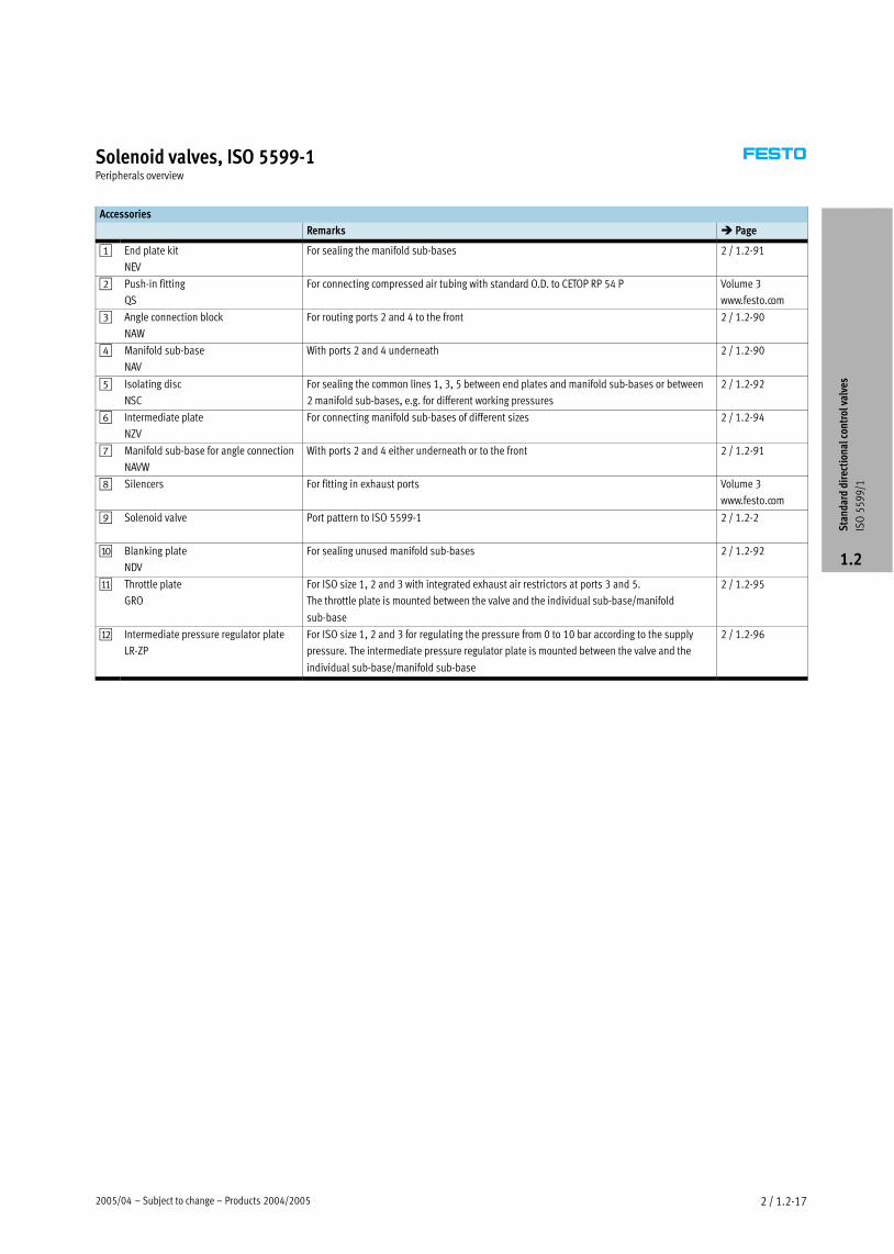
Solenoid valves, ISO 5599−1Peripherals overview
Accessories
Remarks � Page
1 End plate kit
NEV
For sealing the manifold sub−bases 2 / 1.2−91
2 Push−in fitting
QS
For connecting compressed air tubing with standard O.D. to CETOP RP 54 P Volume 3
www.festo.com
3 Angle connection block
NAW
For routing ports 2 and 4 to the front 2 / 1.2−90
4 Manifold sub−base
NAV
With ports 2 and 4 underneath 2 / 1.2−90
5 Isolating disc
NSC
For sealing the common lines 1, 3, 5 between end plates and manifold sub−bases or between
2 manifold sub−bases, e.g. for different working pressures
2 / 1.2−92
6 Intermediate plate
NZV
For connecting manifold sub−bases of different sizes 2 / 1.2−94
7 Manifold sub−base for angle connection
NAVW
With ports 2 and 4 either underneath or to the front 2 / 1.2−91
8 Silencers For fitting in exhaust ports Volume 3
www.festo.com
9 Solenoid valve Port pattern to ISO 5599−1 2 / 1.2−2
aJ Blanking plate
NDV
For sealing unused manifold sub−bases 2 / 1.2−92
aA Throttle plate
GRO
For ISO size 1, 2 and 3 with integrated exhaust air restrictors at ports 3 and 5.
The throttle plate is mounted between the valve and the individual sub−base/manifold
sub−base
2 / 1.2−95
aB Intermediate pressure regulator plate
LR−ZP
For ISO size 1, 2 and 3 for regulating the pressure from 0 to 10 bar according to the supply
pressure. The intermediate pressure regulator plate is mounted between the valve and the
individual sub−base/manifold sub−base
2 / 1.2−96
Sta
ndar
d di
rect
iona
l con
trol
val
ves
ISO
55
99
/1
1.2

Products 2004/2005 – Subject to change – 2004/102 / 1.2−18
Solenoid valves MN1H, ISO 5599−1Technical data – 5/2−way valves
−M− Flow rate
1200 Ī 4500 l/min
−P− Voltage
24 V DC
110, 230 V AC
General technical data
ISO size 1 2 3
Valve function 5/2−way, single solenoid
Constructional design Piston spool
Sealing principle Soft
Actuation type Electrical
Type of reset Mechanical or pneumatic spring
Type of pilot control Piloted
Pilot air supply Internal or external
Direction of flow Non−reversible
Exhaust function With flow control
Manual override Via accessory, detenting
Type of mounting Via through−holes
Mounting position Any
Nominal size [mm] 8 11 14.5
Standard nominal flow rate [l/min] 1200 2300 4500
Grid dimension [mm] 43 56 71
Pneumatic connection on sub−base G¼ Gy G½
Product weight [g] 450 710 1000
Noise level [dB (A)] 85
Operating and environmental conditions
Type of reset Pneumatic Mechanical
Operating medium Filtered compressed air, lubricated or unlubricated
Vacuum
Operating pressure Internal pilot air supply [bar] 2 Ī 10 3 Ī 10p g p
External pilot air supply [bar] –0.9 Ī +16 –0.9 Ī +16
Pilot pressure [bar] 2 Ī 10 3 Ī 10
Ambient temperature [°C] –10 Ī +50
Temperature of medium [°C] –10 Ī +50*
Valve response times [ms]
ISO size 1 2 3
Type of reset Pneumatic Mechanical Pneumatic Mechanical Pneumatic Mechanical
On 23 17 46 24 49 33
Off 32 39 69 62 71 74
Sta
ndar
d di
rect
iona
l con
trol
val
ves
ISO
55
99
/1
1.2

2004/10 – Subject to change – Products 2004/2005 2 / 1.2−19
Solenoid valves MN1H, ISO 5599−1Technical data – 5/2−way valves
Electrical data
N1 solenoid coil
Electrical connection Plug, square design to EN 175301−803, type A
Operating voltage D.C. voltage [V DC] 24p g g
A.C. voltage [V AC] 110/230 (50 Ī 60 Hz)
Coil characteristics D.C. voltage [W] 2.5
A.C. voltage [VA] Pull: 7.5
Hold: 5
Protection class to EN 60 529 IP65
Materials
Sectional view
1
1 Housing Die−cast aluminium, polyacetate
– Seals Nitrile rubber
Note on material Versions free of copper, PTFE and silicone � Ordering data
Sta
ndar
d di
rect
iona
l con
trol
val
ves
ISO
55
99
/1
1.2
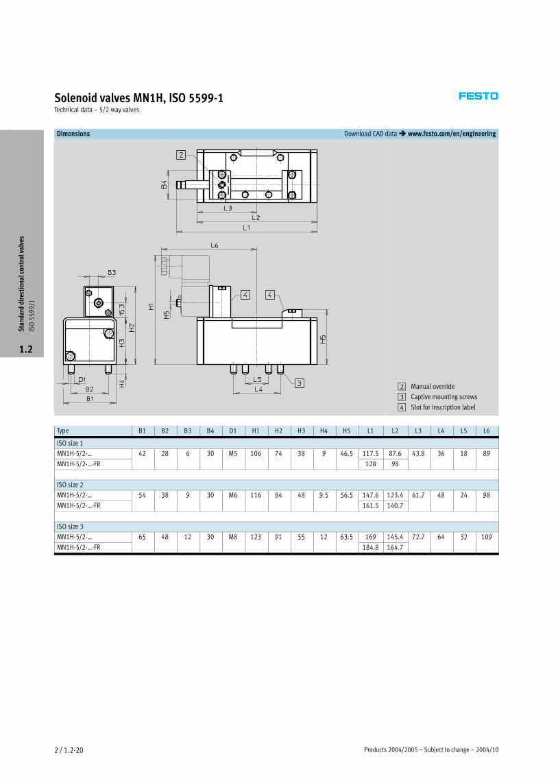
Products 2004/2005 – Subject to change – 2004/102 / 1.2−20
Solenoid valves MN1H, ISO 5599−1Technical data – 5/2−way valves
Dimensions Download CAD data � www.festo.com/en/engineering
2 Manual override
3 Captive mounting screws
4 Slot for inscription label
Type B1 B2 B3 B4 D1 H1 H2 H3 H4 H5 L1 L2 L3 L4 L5 L6
ISO size 1
MN1H−5/2−Ī 42 28 6 30 M5 106 74 38 9 46.5 117.5 87.6 43.8 36 18 89
MN1H−5/2−Ī−FR
3 5 7 3 9 5
128 98
3 3 9
ISO size 2
MN1H−5/2−Ī 54 38 9 30 M6 116 84 48 9.5 56.5 147.6 123.4 61.7 48 24 98
MN1H−5/2−Ī−FR
5 3 9 3 9 5 5 5
161.5 140.7
7 9
ISO size 3
MN1H−5/2−Ī 65 48 12 30 M8 123 91 55 12 63.5 169 145.4 72.7 64 32 109
MN1H−5/2−Ī−FR
5 3 3 9 55 3 5
184.8 164.7
7 7 3 9
Sta
ndar
d di
rect
iona
l con
trol
val
ves
ISO
55
99
/1
1.2

2004/10 – Subject to change – Products 2004/2005 2 / 1.2−21
Solenoid valves MN1H, ISO 5599−1Technical data – 5/2−way valves
Ordering data
Circuit symbol Description ISO size Part No. Type
Without N1 solenoid coil1), 1 159 688 MN1H−5/2−D−1−C,
internal pilot air supply, 184 637 MN1H−5/2−D−1−C−CT2)p pp y,
pneumatic reset 2 159 700 MN1H−5/2−D−2−Cp
184 640 MN1H−5/2−D−2−C−CT2)
3 159 712 MN1H−5/2−D−3−C3
184 643 MN1H−5/2−D−3−C−CT2)
Without N1 solenoid coil1), 1 159 686 MN1H−5/2−D−1−S−C,
external pilot air supply, 2 159 698 MN1H−5/2−D−2−S−Cp pp y,
pneumatic reset 3 159 710 MN1H−5/2 D−3−S−C
Without N1 solenoid coil1), 1 159 687 MN1H−5/2−D−1−FR−C,
internal pilot air supply, 184 638 MN1H−5/2−D−1−FR−C−CT2)p pp y,
mechanical reset 2 159 699 MN1H−5/2−D−2−FR−C
184 641 MN1H−5/2−D−2−FR−C−CT2)
3 159 711 MN1H−5/2−D−3−FR−C3
184 644 MN1H−5/2−D−3−FR−C−CT2)
Without N1 solenoid coil1), 1 159 716 MN1H−5/2−D−1−FR−S−C,
external pilot air supply, 2 159 718 MN1H−5/2−D−2−FR−S−Cp pp y,
mechanical reset 3 160 896 MN1H−5/2−D−3−FR−S−C
1) N1 solenoid coils � 2 / 1.2−100
2) Free of copper, PTFE and silicone
Sta
ndar
d di
rect
iona
l con
trol
val
ves
ISO
55
99
/1
1.2

Products 2004/2005 – Subject to change – 2004/102 / 1.2−22
Solenoid valves JMN1H, ISO 5599−1Technical data – 5/2−way valves, double solenoid
−M− Flow rate
1200 Ī 4500 l/min
−P− Voltage
24 V DC
110, 230, 240 V AC
General technical data
ISO size 1 2 3
Valve function 5/2−way, double solenoid
Constructional design Piston spool
Sealing principle Soft
Actuation type Electrical
Type of reset Mechanical spring
Type of pilot control Piloted
Pilot air supply Internal or external
Direction of flow Non−reversible
Exhaust function With flow control
Manual override Via accessory, detenting
Type of mounting Via through−holes
Mounting position Any
Nominal size [mm] 8 11 14.5
Standard nominal flow rate [l/min] 1200 2300 4500
Grid dimension [mm] 43 56 71
Pneumatic connection on sub−base G¼ Gy G½
Product weight [g] 610 880 1090
Noise level [dB (A)] 85
Operating and environmental conditions
Operating medium Filtered compressed air, lubricated or unlubricated
Vacuum
Operating pressure Internal pilot air supply [bar] 2 Ī 10p g p
External pilot air supply [bar] –0.9 Ī +16
Pilot pressure [bar] 2 Ī 10
Ambient temperature [°C] –10 Ī +50
Temperature of medium [°C] –10 Ī +50*
Valve response times
ISO size 1 2 3
Dominant signal at
14
Dominant signal at
14
Dominant signal at
14
18 12: 18 ms;
14: 15 ms
21 12: 24 ms;
14: 21 ms
21 12: 24 ms;
14: 21 ms
Sta
ndar
d di
rect
iona
l con
trol
val
ves
ISO
55
99
/1
1.2

2004/10 – Subject to change – Products 2004/2005 2 / 1.2−23
Solenoid valves JMN1H, ISO 5599−1Technical data – 5/2−way valves, double solenoid
Electrical data
N1 solenoid coil
Electrical connection Plug, square design to EN 175301−803, type A
Operating voltage D.C. voltage [V DC] 24p g g
A.C. voltage [V AC] 110/230 (50 Ī 60 Hz)
Coil characteristics D.C. voltage [W] 2.5
A.C. voltage [VA] Pull: 7.5
Hold: 5
Protection class to EN 60 529 IP65
Materials
Sectional view
1
1 Housing Die−cast aluminium, polyacetate
– Seals Nitrile rubber
Sta
ndar
d di
rect
iona
l con
trol
val
ves
ISO
55
99
/1
1.2

Products 2004/2005 – Subject to change – 2004/102 / 1.2−24
Solenoid valves JMN1H, ISO 5599−1Technical data – 5/2−way valves, double solenoid
Dimensions Download CAD data � www.festo.com/en/engineering
2 Manual override
3 Captive mounting screws
4 Slot for inscription label
ISO size B1 B2 B3 B4 D1 H1 H2 H3 H4 L1 L2 L3 L4 L5 L6
1 42 28 6 30 M5 106 74 38 9 147.3 87.6 43.8 36 18 89
2 54 38 9 30 M6 116 84 48 9.5 165 123.4 61.7 48 24 98
3 65 48 12 30 M8 123 91 55 12 185.7 145.4 72.7 64 32 109
Sta
ndar
d di
rect
iona
l con
trol
val
ves
ISO
55
99
/1
1.2

2004/10 – Subject to change – Products 2004/2005 2 / 1.2−25
Solenoid valves JMN1H, ISO 5599−1Technical data – 5/2−way valves, double solenoid
Ordering data – Double solenoid valve
Circuit symbol Description ISO size Part No. Type
Without N1 solenoid coil1), 1 159 690 JMN1H−5/2−D−1−C,
internal pilot air supply 2 159 702 JMN1H−5/2−D−2−Cp pp y
3 159 714 JMN1H−5/2−D−3−C
Without N1 solenoid coil1), 1 159 689 JMN1H−5/2−D−1−S−C,
external pilot air supply 2 159 701 JMN1H−5/2−D−2−S−Cp pp y
3 159 713 JMN1H−5/2 D−3−S−C
Without N1 solenoid coil1), 1 159 691 JMN1DH−5/2−D−1−C,
internal pilot air supply, 2 159 703 JMN1DH−5/2−D−2−Cp pp y,
with dominant signal at 14 3 159 715 JMN1DH−5/2−D−3−C
Without N1 solenoid coil1), 1 159 717 JMN1DH−5/2−D−1−S−C,
external pilot air supply, 2 159 719 JMN1DH−5/2−D−2−S−Cp pp y,
with dominant signal at 14 3 160 897 JMN1DH−5/2−D−3−S−C
1) N1 solenoid coils � 2 / 1.2−100
Sta
ndar
d di
rect
iona
l con
trol
val
ves
ISO
55
99
/1
1.2

Products 2004/2005 – Subject to change – 2004/102 / 1.2−26
Solenoid valves MN1H, ISO 5599−1Technical data – 5/3−way valves
−M− Flow rate
1200 Ī 4600 l/min
−P− Voltage
24 V DC
110, 230 V AC
General technical data
ISO size 1 2 3
Valve function 5/3−way, single solenoid
Constructional design Piston spool
Sealing principle Soft
Actuation type Electrical
Type of reset Mechanical spring
Type of pilot control Piloted
Pilot air supply Internal
Direction of flow Non−reversible
Exhaust function With flow control
Manual override Via accessory, detenting
Type of mounting Via through−holes
Mounting position Any
Nominal size [mm] 8 11 14.5
Standard nominal flow rate Closed [l/min] 1200 2300 4100
Exhausted [l/min]
3
4600
Pressurised [l/min] 4000
Grid dimension [mm] 43 56 71
Pneumatic connection on sub−base G¼ Gy G½
Product weight [g] 650 940 1170
Noise level [dB (A)] 85
Operating and environmental conditions
Operating medium Filtered compressed air, lubricated or unlubricated
Vacuum
Operating pressure Internal pilot air supply [bar] 3 Ī 10p g p
External pilot air supply [bar] –0.9 Ī +16
Pilot pressure [bar] 3 Ī 10
Ambient temperature [°C] –10 Ī +50
Temperature of medium [°C] –10 Ī +50*
Valve response times [ms]
ISO size 1 2 3
On Off On Off On Off
With N1 solenoid coil
Closed 20 44 33 82 33 82
Exhausted 20 46 36 84 36 84
Pressurised 20 46 35 78 35 78
Sta
ndar
d di
rect
iona
l con
trol
val
ves
ISO
55
99
/1
1.2

2004/10 – Subject to change – Products 2004/2005 2 / 1.2−27
Solenoid valves MN1H, ISO 5599−1Technical data – 5/3−way valves
Electrical data
N1 solenoid coil
Electrical connection Plug, square design to EN 175301−803, type A
Operating voltage D.C. voltage [V DC] 24p g g
A.C. voltage [V AC] 110/230 (50 Ī 60 Hz)
Coil characteristics D.C. voltage [W] 2.5
A.C. voltage [VA] Pull: 7.5
Hold: 5
Protection class to EN 60 529 IP65
Materials
Sectional view
1
1 Housing Die−cast aluminium, polyacetate
– Seals Nitrile rubber
Note on material Versions free of copper, PTFE and silicone � Ordering data
Sta
ndar
d di
rect
iona
l con
trol
val
ves
ISO
55
99
/1
1.2

Products 2004/2005 – Subject to change – 2004/102 / 1.2−28
Solenoid valves MN1H, ISO 5599−1Technical data – 5/3−way valves
Dimensions Download CAD data � www.festo.com/en/engineering
2 Manual override
3 Captive mounting screws
4 Slot for inscription label
ISO size B1 B2 B3 B4 D1 H1 H2 H3 H4 L1 L2 L3 L4 L5 L6
1 42 28 6 30 M5 106 74 38 9 147.3 108.4 54.2 36 18 89
2 54 38 9 30 M6 116 84 48 9.5 165 158 79 48 24 98
3 65 48 12 30 M8 123 91 55 12 185.7 184 92 64 32 109
Sta
ndar
d di
rect
iona
l con
trol
val
ves
ISO
55
99
/1
1.2

2004/10 – Subject to change – Products 2004/2005 2 / 1.2−29
Solenoid valves MN1H, ISO 5599−1Technical data – 5/3−way valves
Ordering data
Circuit symbol Description ISO size Part No. Type
Without N1 solenoid coil1), 1 159 681 MN1H−5/3G−D−1−C,
normally closed, 184 658 MN1H−5/3G−D−1−C−CT2)y ,
internal pilot air supply 2 159 693 MN1H−5/3G−D−2−Cp pp y
184 660 MN1H−5/3G−D−2−C−CT2)
3 159 705 MN1H−5/3G−D−3−C3
184 662 MN1H−5/3G−D−3−C−CT2)
Without N1 solenoid coil1), 1 159 680 MN1H−5/3G−D−1−S−C,
normally closed, 2 159 692 MN1H−5/3G−D−2−S−Cy ,
external pilot air supply 3 159 704 MN1H−5/3G D−3−S−C
Without N1 solenoid coil1), 1 159 683 MN1H−5/3E−D−1−C,
normally exhausted, 184 652 MN1H−5/3E−D−1−C−CT2)y ,
internal pilot air supply 2 159 695 MN1H−5/3E−D−2−Cp pp y
184 654 MN1H−5/3E−D−2−C−CT2)
3 159 707 MN1H−5/3E−D−3−C3
184 656 MN1H−5/3E−D−3−C−CT2)
Without N1 solenoid coil1), 1 159 682 MN1H−5/3E−D−1−S−C,
normally exhausted, 2 159 694 MN1H−5/3E−D−2−S−Cy ,
external pilot air supply 3 159 706 MN1H−5/3E−D−3−S−C
Without N1 solenoid coil1), 1 159 685 MN1H−5/3B−D−1−C,
normally pressurised, 184 646 MN1H−5/3B−D−1−C−CT2)y p ,
internal pilot air supply 2 159 697 MN1H−5/3B−D−2−Cp pp y
184 648 MN1H−5/3B−D−2−C−CT2)
3 159 709 MN1H−5/3B−D−3−C3
184 650 MN1H−5/3B−D−3−C−CT2)
Without N1 solenoid coil1), 1 159 684 MN1H−5/3B−D−1−S−C,
normally pressurised, 2 159 696 MN1H−5/3B−D−2−S−Cy p ,
external pilot air supply 3 159 708 MN1H−5/3B−D−3−S−C
1) N1 solenoid coils � 2 / 1.2−100
2) Free of copper, PTFE and silicone
Sta
ndar
d di
rect
iona
l con
trol
val
ves
ISO
55
99
/1
1.2

Products 2004/2005 – Subject to change – 2003/102 / 1.2−30
Solenoid valves MFH, ISO 5599−1Technical data – 5/2−way valves
−M− Flow rate
1200 Ī 4500 l/min
−P− Voltage
12, 24, 42, 48 V DC
24, 42, 48, 110, 230,
240 V AC
General technical data
ISO size 1 2 3
Valve function 5/2−way, single solenoid
Constructional design Piston spool
Sealing principle Soft
Actuation type Electrical
Type of reset Mechanical or pneumatic spring
Type of pilot control Piloted
Pilot air supply Internal
Direction of flow Non−reversible
Exhaust function With flow control
Manual override Via accessory, detenting
Type of mounting Via through−holes
Mounting position Any
Nominal size [mm] 8 11 14.5
Standard nominal flow rate [l/min] 1200 2300 4500
Grid dimension [mm] 43 56 71
Pneumatic connection on sub−base G¼ Gy G½
Product weight [g] 390 650 960
Noise level [dB (A)] 85
Operating and environmental conditions
Type of reset Pneumatic Mechanical
Operating medium Filtered compressed air, lubricated or unlubricated
Vacuum
Operating pressure Internal pilot air supply [bar] 2 Ī 10 3 Ī 10p g p
External pilot air supply [bar] –0.9 Ī +16 –0.9 Ī +16
Pilot pressure [bar] 2 Ī 10 3 Ī 10
Ambient temperature [°C] –5 Ī +40
Temperature of medium [°C] –10 Ī +60*
Valve response times [ms]
ISO size 1 2 3
Type of reset Pneumatic Mechanical Pneumatic Mechanical Pneumatic Mechanical
With F solenoid coil
On 23 16 48 27 60 30
Off 35 45 71 73 66 82
Sta
ndar
d di
rect
iona
l con
trol
val
ves
ISO
55
99
/1
1.2

2003/10 – Subject to change – Products 2004/2005 2 / 1.2−31
Solenoid valves MFH, ISO 5599−1Technical data – 5/2−way valves
Electrical data
F solenoid coil
Electrical connection Design Plug vanes for plug sockets MSSD−F, KMF
Operating voltage D.C. voltage [V DC] 12, 24, 42, 48p g g
A.C. voltage [V AC] 24, 42, 48, 110, 230, 240 (50 Ī 60 Hz)
Coil characteristics D.C. voltage [W] 4.5
A.C. voltage [VA] Pull: 7.5
Hold: 6
Protection class to EN 60 529 IP65
Materials
Sectional view
1
1 Housing Die−cast aluminium, polyacetate
– Seals Nitrile rubber
Sta
ndar
d di
rect
iona
l con
trol
val
ves
ISO
55
99
/1
1.2

Products 2004/2005 – Subject to change – 2003/102 / 1.2−32
Solenoid valves MFH, ISO 5599−1Technical data – 5/2−way valves
Dimensions Download CAD data � www.festo.com/en/engineering
2 Manual override
3 Captive mounting screws
4 Slot for inscription label
Type B1 B2 B3 B4 D1 H1 H2 H3 H4 H5 L1 L2 L3 L4 L5 L6
ISO size 1
MFH−5/2−Ī 42 28 6 30 M5 100 70.3 38 9 46.5 115 87.6 43.8 36 18 89
MFH−5/2−Ī−FR
3 5 7 3 3 9 5
125.6 98
3 3 9
ISO size 2
MFH−5/2−Ī 54 38 9 30 M6 110 80.3 48 9.5 56.5 142 123.4 61.7 48 24 98
MFH−5/2−Ī−FR
5 3 9 3 3 9 5 5 5
159.4 140.7
7 9
ISO size 3
MFH−5/2−Ī 65 48 12 30 M8 117 87.3 55 12 63.5 163 145.4 72.7 64 32 109
MFH−5/2−Ī−FR
5 3 7 7 3 55 3 5
182 164.7
7 7 3 9
Sta
ndar
d di
rect
iona
l con
trol
val
ves
ISO
55
99
/1
1.2

2003/10 – Subject to change – Products 2004/2005 2 / 1.2−33
Solenoid valves MFH, ISO 5599−1Technical data – 5/2−way valves
Ordering data
Circuit symbol Description ISO size Part No. Type
Without F solenoid coil1), 1 150 981 MFH−5/2−D−1−C,
pneumatic reset, 2 151 851 MFH−5/2−D−2−Cp ,
internal pilot air supply 3 151 870 MFH−5/2−D−3−C
Without F solenoid coil1), 1 152 562 MFH−5/2−D−1−S−C,
pneumatic reset, 2 151 022 MFH−5/2−D−2−S−Cp ,
external pilot air supply 3 151 032 MFH−5/2−D−3−S−C
Without F solenoid coil1), 1 151 016 MFH−5/2−D−1−FR−C,
mechanical reset, 2 151 709 MFH−5/2−D−2−FR−C,
internal pilot air supply 3 151 711 MFH−5/2−D−3−FR−C
1) F solenoid coils � 2 / 1.2−100
Sta
ndar
d di
rect
iona
l con
trol
val
ves
ISO
55
99
/1
1.2

Products 2004/2005 – Subject to change – 2003/102 / 1.2−34
Solenoid valves JMFH, ISO 5599−1Technical data – 5/2−way valves, double solenoid
−M− Flow rate
1200 Ī 4500 l/min
−P− Voltage
12, 24, 42, 48 V DC
24, 42, 48, 110, 230,
240 V AC
General technical data
ISO size 1 2 3
Valve function 5/2−way, double solenoid
Constructional design Piston spool
Sealing principle Soft
Actuation type Electrical
Type of pilot control Piloted
Pilot air supply Internal or external
Direction of flow Non−reversible
Exhaust function With flow control
Manual override Via accessory, detenting
Type of mounting Via through−holes
Mounting position Any
Nominal size [mm] 8 11 14.5
Standard nominal flow rate [l/min] 1200 2300 4500
Grid dimension [mm] 43 56 71
Pneumatic connection on sub−base G¼ Gy G½
Product weight [g] 490 750 1060
Noise level [dB (A)] 85
Operating and environmental conditions
Operating medium Filtered compressed air, lubricated or unlubricated
Vacuum
Operating pressure Internal pilot air supply [bar] 2 Ī 10p g p
External pilot air supply [bar] –0.9 Ī +16
Pilot pressure [bar] 2 Ī 10
Ambient temperature [°C] –5 Ī +40
Temperature of medium [°C] –10 Ī +60*
Valve response times [ms]
ISO size 1 2 3
Dominant signal at
14
Dominant signal at
14
Dominant signal at
14
With F solenoid coil
16 16 18 18 18 18
Sta
ndar
d di
rect
iona
l con
trol
val
ves
ISO
55
99
/1
1.2

2003/10 – Subject to change – Products 2004/2005 2 / 1.2−35
Solenoid valves JMFH, ISO 5599−1Technical data – 5/2−way valves, double solenoid
Electrical data
ISO size 1, 2, 3
F solenoid coil
Electrical connection Design Plug vanes for plug sockets MSSD−F, KMF
Operating voltage D.C. voltage [V DC] 12, 24, 42, 48p g g
A.C. voltage [V AC] 24, 42, 48, 110, 230, 240 (50 Ī 60 Hz)
Coil characteristics D.C. voltage [W] 4.5
A.C. voltage [VA] Pull: 7.5
Hold: 6
Protection class to EN 60 529 IP65
Materials
Sectional view
1
1 Housing Die−cast aluminium, polyacetate
– Seals Nitrile rubber
Sta
ndar
d di
rect
iona
l con
trol
val
ves
ISO
55
99
/1
1.2

Products 2004/2005 – Subject to change – 2003/102 / 1.2−36
Solenoid valves JMFH, ISO 5599−1Technical data – 5/2−way valves, double solenoid
Dimensions Download CAD data � www.festo.com/en/engineering
2 Manual override
3 Captive mounting screws
4 Slot for inscription label
ISO size B1 B2 B3 B4 D1 H1 H2 H3 H4 L1 L2 L3 L4 L5 L6
1 42 28 6 30 M5 100 70.3 38 9 142.6 87.6 43.8 36 18 88
2 54 38 9 30 M6 110 80.3 48 9.5 160.4 123.4 61.7 48 24 97
3 65 48 12 30 M8 117 87.3 55 12 181 145.4 72.7 64 32 109
Ordering data
Circuit symbol Description ISO size Part No. Type
Without F solenoid coil1), 1 150 980 JMFH−5/2−D−1−C,
internal pilot air supply 2 151 852 JMFH−5/2−D−2−Cp pp y
3 151 871 JMFH−5/2−D−3−C
Without F solenoid coil1), 1 152 563 JMFH−5/2−D−1−S−C,
external pilot air supply 2 151 023 JMFH−5/2−D−2−S−Cp pp y
3 151 033 JMFH−5/2−D−3−S−C
Without F solenoid coil1), 1 151 019 JMFDH−5/2−D−1−C,
internal pilot air supply, 2 151 853 JMFDH−5/2−D−2−Cp pp y,
with dominant signal at 14 3 151 872 JMFDH−5/2−D−3−C
1) F solenoid coils � 2 / 1.2−100
Sta
ndar
d di
rect
iona
l con
trol
val
ves
ISO
55
99
/1
1.2
2003/10 – Subject to change – Products 2004/2005 2 / 1.2−37
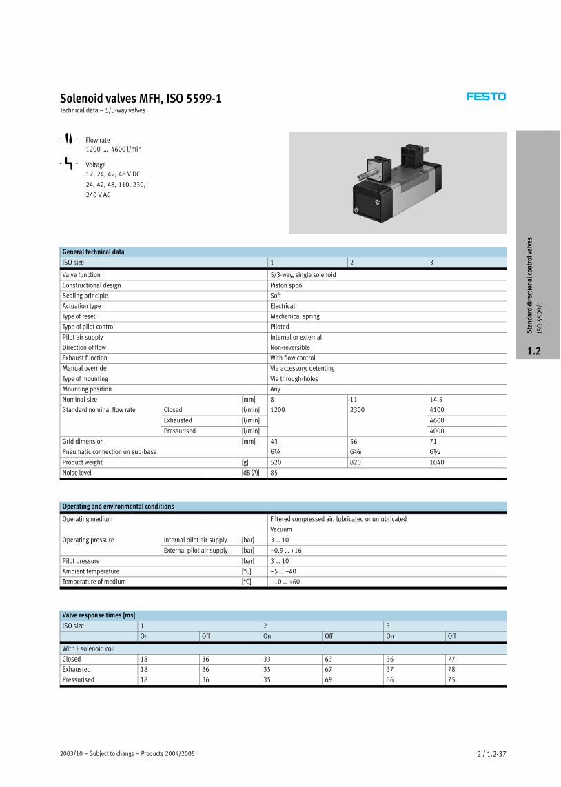
Solenoid valves MFH, ISO 5599−1Technical data – 5/3−way valves
−M− Flow rate
1200 Ī 4600 l/min
−P− Voltage
12, 24, 42, 48 V DC
24, 42, 48, 110, 230,
240 V AC
General technical data
ISO size 1 2 3
Valve function 5/3−way, single solenoid
Constructional design Piston spool
Sealing principle Soft
Actuation type Electrical
Type of reset Mechanical spring
Type of pilot control Piloted
Pilot air supply Internal or external
Direction of flow Non−reversible
Exhaust function With flow control
Manual override Via accessory, detenting
Type of mounting Via through−holes
Mounting position Any
Nominal size [mm] 8 11 14.5
Standard nominal flow rate Closed [l/min] 1200 2300 4100
Exhausted [l/min]
3
4600
Pressurised [l/min] 4000
Grid dimension [mm] 43 56 71
Pneumatic connection on sub−base G¼ Gy G½
Product weight [g] 520 820 1040
Noise level [dB (A)] 85
Operating and environmental conditions
Operating medium Filtered compressed air, lubricated or unlubricated
Vacuum
Operating pressure Internal pilot air supply [bar] 3 Ī 10p g p
External pilot air supply [bar] –0.9 Ī +16
Pilot pressure [bar] 3 Ī 10
Ambient temperature [°C] –5 Ī +40
Temperature of medium [°C] –10 Ī +60*
Valve response times [ms]
ISO size 1 2 3
On Off On Off On Off
With F solenoid coil
Closed 18 36 33 63 36 77
Exhausted 18 36 35 67 37 78
Pressurised 18 36 35 69 36 75
Sta
ndar
d di
rect
iona
l con
trol
val
ves
ISO
55
99
/1
1.2
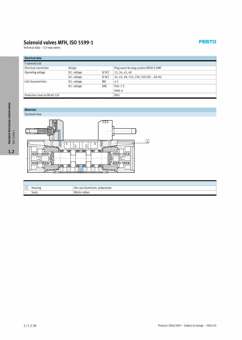
Products 2004/2005 – Subject to change – 2003/102 / 1.2−38
Solenoid valves MFH, ISO 5599−1Technical data – 5/3−way valves
Electrical data
F solenoid coil
Electrical connection Design Plug vanes for plug sockets MSSD−F, KMF
Operating voltage D.C. voltage [V DC] 12, 24, 42, 48p g g
A.C. voltage [V AC] 24, 42, 48, 110, 230, 240 (50 Ī 60 Hz)
Coil characteristics D.C. voltage [W] 4.5
A.C. voltage [VA] Pull: 7.5
Hold: 6
Protection class to EN 60 529 IP65
Materials
Sectional view
1
1 Housing Die−cast aluminium, polyacetate
– Seals Nitrile rubber
Sta
ndar
d di
rect
iona
l con
trol
val
ves
ISO
55
99
/1
1.2

2003/10 – Subject to change – Products 2004/2005 2 / 1.2−39
Solenoid valves MFH, ISO 5599−1Technical data – 5/3−way valves
Dimensions Download CAD data � www.festo.com/en/engineering
2 Manual override
3 Captive mounting screws
4 Slot for inscription label
ISO size B1 B2 B3 B4 D1 H1 H2 H3 H4 L1 L2 L3 L4 L5 L6
1 42 28 6 30 M5 100 70.3 38 9 142.6 108.4 54.2 36 18 89
2 54 38 9 30 M6 110 80.3 48 9.5 160 158 79 48 24 98
3 65 48 12 30 M8 117 87.3 55 12 181 184 92 64 32 109
Sta
ndar
d di
rect
iona
l con
trol
val
ves
ISO
55
99
/1
1.2

Products 2004/2005 – Subject to change – 2003/102 / 1.2−40
Solenoid valves MFH, ISO 5599−1Technical data – 5/3−way valves
Ordering data
Circuit symbol Description ISO size Part No. Type
Without F solenoid coil1), 1 150 982 MFH−5/3G−D−1−C,
normally closed, 2 151 854 MFH−5/3G−D−2−Cy ,
internal pilot air supply 3 151 873 MFH−5/3G−D−3−C
Without F solenoid coil1), 1 152 564 MFH−5/3G−D−1−S−C,
normally closed, 2 151 024 MFH−5/3G−D−2−S−Cy ,
external pilot air supply 3 151 034 MFH−5/3G−D−3−S−C
Without F solenoid coil1), 1 150 983 MFH−5/3E−D−1−C,
normally exhausted, 2 151 855 MFH−5/3E−D−2−Cy ,
internal pilot air supply 3 151 874 MFH−5/3E−D−3−C
Without F solenoid coil1), 1 152 565 MFH−5/3E−D−1−S−C,
normally exhausted, 2 151 025 MFH−5/3E−D−2−S−Cy ,
external pilot air supply 3 151 035 MFH−5/3E−D−3−S−C
Without F solenoid coil1), 1 150 984 MFH−5/3B−D−1−C,
normally pressurised, 2 151 856 MFH−5/3B−D−2−Cy p ,
internal pilot air supply 3 151 875 MFH−5/3B−D−3−C
Without F solenoid coil1), 1 152 566 MFH−5/3B−D−1−S−C,
normally pressurised, 2 151 026 MFH−5/3B−D−2−S−Cy p ,
external pilot air supply 3 151 036 MFH−5/3B−D−3−S−C
1) F solenoid coils � 2 / 1.2−100
Sta
ndar
d di
rect
iona
l con
trol
val
ves
ISO
55
99
/1
1.2

2003/10 – Subject to change – Products 2004/2005 2 / 1.2−41
Solenoid valves MEBH, ISO 5599−1Technical data – 5/2−way valves
−M− Flow rate
1200 Ī 4500 l/min
−P− Voltage
24 V DC
General technical data
ISO size 1 2 3
Valve function 5/2−way, single solenoid
Constructional design Piston spool
Sealing principle Soft
Actuation type Electrical
Type of reset Mechanical or pneumatic spring
Type of pilot control Piloted
Pilot air supply Internal
Direction of flow Non−reversible
Exhaust function With flow control
Manual override Via accessory, detenting
Type of mounting Via through−holes
Mounting position Any
Nominal size [mm] 8 11 14.5
Standard nominal flow rate [l/min] 1200 2300 4500
Grid dimension [mm] 43 56 71
Pneumatic connection on sub−base G¼ Gy G½
Product weight [g] 550 700 1000
Noise level [dB (A)] 85
Operating and environmental conditions
Type of reset Pneumatic Mechanical
Operating medium Filtered compressed air, lubricated or unlubricated
Vacuum
Operating pressure Internal pilot air supply [bar] 2 Ī 10 3 Ī 10p g p
External pilot air supply [bar] –0.9 Ī +16 –0.9 Ī +16
Pilot pressure [bar] 2 Ī 10 3 Ī 10
Ambient temperature [°C] –5 Ī +50
Temperature of medium [°C] –5 Ī +50*
Valve response times [ms]
ISO size 1 2 3
Type of reset Pneumatic Mechanical Pneumatic Mechanical Pneumatic Mechanical
With EB solenoid coil
On 20 15 50 33 59 28
Off 33 50 85 103 87 109
Sta
ndar
d di
rect
iona
l con
trol
val
ves
ISO
55
99
/1
1.2
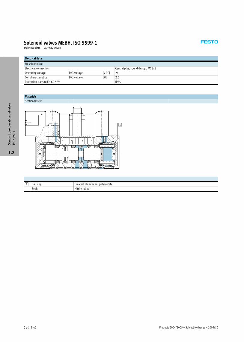
Products 2004/2005 – Subject to change – 2003/102 / 1.2−42
Solenoid valves MEBH, ISO 5599−1Technical data – 5/2−way valves
Electrical data
EB solenoid coil
Electrical connection Central plug, round design, M12x1
Operating voltage D.C. voltage [V DC] 24
Coil characteristics D.C. voltage [W] 2.5
Protection class to EN 60 529 IP65
Materials
Sectional view
1
1 Housing Die−cast aluminium, polyacetate
– Seals Nitrile rubber
Sta
ndar
d di
rect
iona
l con
trol
val
ves
ISO
55
99
/1
1.2

2003/10 – Subject to change – Products 2004/2005 2 / 1.2−43
Solenoid valves MEBH, ISO 5599−1Technical data – 5/2−way valves
Dimensions Download CAD data � www.festo.com/en/engineering
1 Attachment of plug socket
adjustable by 3x 30°
2 Manual override
3 Captive mounting screws
5 LED display
6 Angled socket
SEA−M12−4WD−PG7
� 2 / 1.2−102
Type B1 B2 B3 B4 D1 H1 H2 H3 H4 H5 L1 L2 L3 L4 L5 L6
ISO size 1
MEBH−5/2−Ī 42 28 6 17.5 M5 110 80.3 38 9 74.7 110.8 87.6 43.8 36 18 67
MEBH−5/2−Ī−FR
7 5 5 3 3 9 7 7
121.3 98
3 3 7
ISO size 2
MEBH−5/2−Ī 54 38 9 17.5 M6 120 90.1 48 9.5 84.2 137.6 123.4 61.7 48 24 75.9
MEBH−5/2−Ī−FR
5 3 9 7 5 9 9 5
154.9 140.7
7 75 9
ISO size 3
MEBH−5/2−Ī 65 48 12 17.5 M8 130 97.8 55 12 93.1 158.7 145.4 72.7 64 32 86
MEBH−5/2−Ī−FR
5 7 5 3 97 55 93
178 164.7
7 7 3
M12 central plug – Terminal allocation
Mono connection
3
2
4
1 1 Unused
2 Unused
3 com (–)
4 Signal (+) Solenoid 14
Sta
ndar
d di
rect
iona
l con
trol
val
ves
ISO
55
99
/1
1.2

Products 2004/2005 – Subject to change – 2003/102 / 1.2−44
Solenoid valves MEBH, ISO 5599−1Technical data – 5/2−way valves
Ordering data
Circuit symbol Description Voltage ISO size Part No. Type
With EB solenoid coil, 24 V DC 1 184 493 MEBH−5/2−D−1−ZSR−C,
with central plug, 2 184 500 MEBH−5/2−D−2−ZSR−Cp g,
pneumatic reset, 3 184 507 MEBH−5/2−D−3−ZSR−Cp ,
internal pilot air supply
With EB solenoid coil, 24 V DC 1 184 494 MEBH−5/2−D−1−ZSR−FR−C,
with central plug, 2 184 501 MEBH−5/2−D−2−ZSR−FR−Cp g,
mechanical reset, 3 184 508 MEBH−5/2−D−3−ZSR−FR−C,
internal pilot air supply
Sta
ndar
d di
rect
iona
l con
trol
val
ves
ISO
55
99
/1
1.2

2003/10 – Subject to change – Products 2004/2005 2 / 1.2−45
Solenoid valves JMEBH, ISO 5599−1Technical data – 5/2−way valves, double solenoid
−M− Flow rate
1200 Ī 4500 l/min
−P− Voltage
24 V DC
General technical data
ISO size 1 2 3
Valve function 5/2−way, double solenoid
Constructional design Piston spool
Sealing principle Soft
Actuation type Electrical
Type of pilot control Piloted
Pilot air supply Internal or external
Direction of flow Non−reversible
Exhaust function With flow control
Manual override Via accessory, detenting
Type of mounting Via through−holes
Mounting position Any
Nominal size [mm] 8 11 14.5
Standard nominal flow rate [l/min] 1200 2300 4500
Grid dimension [mm] 43 56 71
Pneumatic connection on sub−base G¼ Gy G½
Product weight [g] 600 770 1080
Noise level [dB (A)] 85
Operating and environmental conditions
Operating medium Filtered compressed air, lubricated or unlubricated
Vacuum
Operating pressure Internal pilot air supply [bar] 2 Ī 10p g p
External pilot air supply [bar] –0.9 Ī +16
Pilot pressure [bar] 2 Ī 10
Ambient temperature [°C] –5 Ī +50
Temperature of medium [°C] –5 Ī +50*
Valve response times [ms]
ISO size 1 2 3
Dominant signal at Dominant signal at Dominant signal atg
14
g
14
g
14
With EB solenoid coil
Changeover 12 13 15 23 16 20
Sta
ndar
d di
rect
iona
l con
trol
val
ves
ISO
55
99
/1
1.2
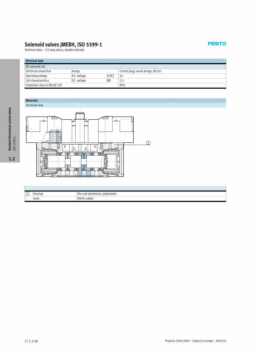
Products 2004/2005 – Subject to change – 2003/102 / 1.2−46
Solenoid valves JMEBH, ISO 5599−1Technical data – 5/2−way valves, double solenoid
Electrical data
EB solenoid coil
Electrical connection Design Central plug, round design, M12x1
Operating voltage D.C. voltage [V DC] 24
Coil characteristics D.C. voltage [W] 2.5
Protection class to EN 60 529 IP65
Materials
Sectional view
1
1 Housing Die−cast aluminium, polyacetate
– Seals Nitrile rubber
Sta
ndar
d di
rect
iona
l con
trol
val
ves
ISO
55
99
/1
1.2

2003/10 – Subject to change – Products 2004/2005 2 / 1.2−47
Solenoid valves JMEBH, ISO 5599−1Technical data – 5/2−way valves, double solenoid
Dimensions Download CAD data � www.festo.com/en/engineering
1 Attachment of plug socket
adjustable by 3x 30°
2 Manual override
3 Captive mounting screws
5 LED display
6 Angled socket
SEA−M12−4WD−PG7
� 2 / 1.2−102
ISO size B1 B2 B3 B4 D1 H1 H2 H3 H4 H5 L1 L2 L3 L4 L5 L6
1 42 28 6 17.5 M5 110 80.3 38 9 74.7 134 87.6 43.8 36 18 67
2 54 38 9 17.5 M6 120 90.1 48 9.5 84.2 151.8 123.4 61.7 48 24 75.9
3 65 48 12 17.5 M8 130 97.8 55 12 93.1 171.9 145.4 72.7 64 32 86
M12 central plug – Terminal allocation
Duo connection
3
2
4
1 1 Unused
2 Signal (+) Solenoid 12
3 com (–)
4 Signal (+) Solenoid 14
Sta
ndar
d di
rect
iona
l con
trol
val
ves
ISO
55
99
/1
1.2

Products 2004/2005 – Subject to change – 2003/102 / 1.2−48
Solenoid valves JMEBH, ISO 5599−1Technical data – 5/2−way valves, double solenoid
Ordering data
Circuit symbol Solenoid coil Voltage ISO size Part No. Type
With EB solenoid coil, 24 V DC 1 184 495 JMEBH−5/2−D−1−ZSR−C,
with central plug, 2 184 502 JMEBH−5/2−D−2−ZSR−Cp g,
internal pilot air supply 3 184 509 JMEBH−5/2−D−3−ZSR−C
With EB solenoid coil, 24 V DC 1 184 496 JMEBDH−5/2−D−1−ZSR−C,
with central plug, 2 184 503 JMEBDH−5/2−D−2−ZSR−Cp g,
internal pilot air supply, 3 184 510 JMEBDH−5/2−D−3−ZSR−Cp pp y,
with dominant signal at 14
Sta
ndar
d di
rect
iona
l con
trol
val
ves
ISO
55
99
/1
1.2

2003/10 – Subject to change – Products 2004/2005 2 / 1.2−49
Solenoid valves MEBH, ISO 5599−1Technical data – 5/3−way valves
−M− Flow rate
1200 Ī 4600 l/min
−P− Voltage
24 V DC
General technical data
ISO size 1 2 3
Valve function 5/3−way, single solenoid
Constructional design Piston spool
Sealing principle Soft
Actuation type Electrical
Type of reset Mechanical spring
Type of pilot control Piloted
Pilot air supply Internal
Direction of flow Non−reversible
Exhaust function With flow control
Manual override Via accessory, detenting
Type of mounting Via through−holes
Mounting position Any
Nominal size [mm] 8 11 14.5
Standard nominal flow rate Closed [l/min] 1200 2300 4100
Exhausted [l/min]
3
4600
Pressurised [l/min] 4000
Grid dimension [mm] 43 56 71
Pneumatic connection on sub−base G¼ Gy G½
Product weight [g] 630 800 1120
Noise level [dB (A)] 85
Operating and environmental conditions
Operating medium Filtered compressed air, lubricated or unlubricated
Vacuum
Operating pressure Internal pilot air supply [bar] 3 Ī 10p g p
External pilot air supply [bar] –0.9 Ī +16
Pilot pressure [bar] 3 Ī 10
Ambient temperature [°C] –5 Ī +50
Temperature of medium [°C] –5 Ī +50*
Valve response times [ms]
ISO size 1 2 3
On Off On Off On Off
With EB solenoid coil
19 68 30 106 38 130
Sta
ndar
d di
rect
iona
l con
trol
val
ves
ISO
55
99
/1
1.2

Products 2004/2005 – Subject to change – 2003/102 / 1.2−50
Solenoid valves MEBH, ISO 5599−1Technical data – 5/3−way valves
Electrical data
EB solenoid coil
Electrical connection Central plug, round design, M12x1
Operating voltage D.C. voltage [V DC] 24
Coil characteristics D.C. voltage [W] 2.5
Protection class to EN 60 529 IP65
Materials
Sectional view
1
1 Housing Die−cast aluminium, polyacetate
– Seals Nitrile rubber
Sta
ndar
d di
rect
iona
l con
trol
val
ves
ISO
55
99
/1
1.2

2003/10 – Subject to change – Products 2004/2005 2 / 1.2−51
Solenoid valves MEBH, ISO 5599−1Technical data – 5/3−way valves
Dimensions Download CAD data � www.festo.com/en/engineering
1 Attachment of plug socket
adjustable by 3x 30°
2 Manual override
3 Captive mounting screws
5 LED display
6 Angled socket
SEA−M12−4WD−PG7
� 2 / 1.2−102
ISO size B1 B2 B3 B4 D1 H1 H2 H3 H4 H5 L1 L2 L3 L4 L5 L6
1 42 28 6 17.5 M5 110 80.3 38 9 74.7 134 108.4 54.2 36 18 67
2 54 38 9 17.5 M6 120 90.1 48 9.5 84.2 151.8 158 79 48 24 75.9
3 65 48 12 17.5 M8 130 97.8 55 12 93.1 171.9 184 92 64 32 86
M12 central plug – Terminal allocation
Duo connection
3
2
4
1 1 Unused
2 Signal (+) Solenoid 12
3 com (–)
4 Signal (+) Solenoid 14
Sta
ndar
d di
rect
iona
l con
trol
val
ves
ISO
55
99
/1
1.2

Products 2004/2005 – Subject to change – 2003/102 / 1.2−52
Solenoid valves MEBH, ISO 5599−1Technical data – 5/3−way valves
Ordering data
Circuit symbol Description Voltage ISO size Part No. Type
With EB solenoid coil, 24 V DC 1 184 498 MEBH−5/3G−D−1−ZSR−C,
with central plug, 2 184 505 MEBH−5/3G−D−2−ZSR−Cp g,
normally closed, 3 184 512 MEBH−5/3G−D−3−ZSR−Cy ,
internal pilot air supply
With EB solenoid coil, 24 V DC 1 184 497 MEBH−5/3E−D−1−ZSR−C,
with central plug, 2 184 504 MEBH−5/3E−D−2−ZSR−Cp g,
normally exhausted, 3 184 511 MEBH−5/3E−D−3−ZSR−Cy ,
internal pilot air supply
With EB solenoid coil, 24 V DC 1 184 499 MEBH−5/3B−D−1−ZSR−C,
with central plug, 2 184 506 MEBH−5/3B−D−2−ZSR−Cp g,
normally pressurised, 3 184 513 MEBH−5/3B−D−3−ZSR−Cy p ,
internal pilot air supply
Sta
ndar
d di
rect
iona
l con
trol
val
ves
ISO
55
99
/1
1.2

2005/04 – Subject to change – Products 2004/2005 2 / 1.2−53
Solenoid valves MDH−M12, ISO 5599−1Technical data – 5/2−way valves
−M− Flow rate
1,200 Ī 4,500 l/min
−P− Voltage
24 V DC
General technical data
ISO size 1 2 3
Valve function 5/2−way, monostable
Design Piston slide
Sealing principle Soft
Actuation type Electrical
Type of reset Mechanical or pneumatic spring
Type of actuation Piloted
Pilot air supply Internal or external
Direction of flow Reversible for external pilot air supply
Exhaust function Restrictablel
Manual override Via tool accessory, detenting
Type of mounting Via through−holes
Mounting position Any
Nominal size [mm] 8 11 14.5
Standard nominal flow rate [l/min] 1,200 2,300 4,500
Grid dimension [mm] 43 56 71
Pneumatic connection on sub−base G¼ Gy G½
Product weight [g] 420 810 1,000
Operating and environmental conditions
Type of reset pneumatic spring mechanical spring
Operating medium Dried compressed air, lubricated or unlubricated, grade of filtration 40�m
Vacuum
Operating pressure internal pilot air supply [bar] 2 Ī 10 3 Ī 10p g p
external pilot air supply [bar] –0.9 Ī +16
Pilot pressure [bar] 2 Ī 10 3 Ī 10
Ambient temperature [°C] –10 Ī +50
Temperature of medium [°C] –10 Ī +50*
Valve response times
ISO size 1 2 3
Type of reset pneumatic mechanical pneumatic mechanical pneumatic mechanical
D solenoid coil with M12x1 plug
On [ms] 25 20 45 25 55 30
Off [ms] 36 42 60 60 60 70
Sta
ndar
d di
rect
iona
l con
trol
val
ves
ISO
55
99
/1
1.2

Products 2004/2005 – Subject to change – 2005/042 / 1.2−54
Solenoid valves MDH−M12, ISO 5599−1Technical data – 5/2−way valves
Electrical data
D solenoid coil with round plug M12x1
Electrical connection Type M12X1
Coil characteristics D.C. voltage [V DC] 21.6Ī26.4
Power [Watt] 2.7
Duty cycle % 100
Protection class to EN 60 529 IP65
Materials
Sectional view
1
1 Body Die−cast aluminium, polyacetate
– Seals Nitrile rubber
Sta
ndar
d di
rect
iona
l con
trol
val
ves
ISO
55
99
/1
1.2

2005/04 – Subject to change – Products 2004/2005 2 / 1.2−55
Solenoid valves MDH−M12, ISO 5599−1Technical data – 5/2−way valves
Dimensions Download CAD data � www.festo.com/en/engineering
1 Solenoid coil can be reposi-
tioned by 90° regardless of
manual override
2 Manual override facility
3 Captive mounting screws
4 Slot for inscription label
5 LED display
6 Plug socket M12x1
Coil 2−pin to VDMA
Coil 4−pin to Desina
Type B1 B2 B3 B4 D1 H1 H2 H3 H4 H5 L1 L2 L3 L4 L5
ISO size 1
MDH−5/2−Ī 42 28 6 30 M5 87.2 77.3 38 9 46.5 121.8 87.6 43.8 36 18
MDH−5/2−Ī−FR
3 5 7 77 3 3 9 5
132.2 98
3 3
ISO size 2
MDH−5/2−Ī 54 38 9 30 M6 97.2 87.2 48 9.5 56.5 144.6 123.4 61.7 48 24
MDH−5/2−Ī−FR
5 3 9 3 97 7 9 5 5 5
161.9 140.6
7
ISO size 3
MDH−5/2−Ī 65 48 12 30 M8 104.2 94.2 55 12 62.7 165.9 145.4 72.7 64 32
MDH−5/2−Ī−FR
5 3 9 55 7
185.2 164.7
7 7 3
M12 plug – Pin allocation 2−pin to VDMA
3
2
4
1 1 Unused
2 Unused
3 com (–)
4 Signal (+)
M12 plug – Pin allocation 4−pin to Desina
1 connected with 2
2 connected with 1
3 com (–)
4 Signal (+)
Sta
ndar
d di
rect
iona
l con
trol
val
ves
ISO
55
99
/1
1.2

Products 2004/2005 – Subject to change – 2005/042 / 1.2−56
Solenoid valves MDH−M12, ISO 5599−1Technical data – 5/2−way valves
Ordering data
Circuit symbol Description ISO Coil 2−pin to VDMA Coil 4−pin to Desinay p
size Part No. Type Part No. Type
Type of reset:
— pneumatic
1 197 125 MDH−5/2−D−1−M12−C 540 803 MDH−5/2−D−1−M12D−C
— pneumatic
Pilot air supply:2 533 008 MDH−5/2−D−2−M12−C 540 812 MDH−5/2−D−2−M12D−C
pp y
— internal 3 533 009 MDH−5/2−D−3−M12−C 540 819 MDH−5/2−D−3−M12D−C
Type of reset:
— pneumatic
1 533 332 MDH−5/2−D−1−S−M12−C 540 810 MDH−5/2−D−1−S−M12D−C
— pneumatic
Pilot air supply:pp y
— external
Type of reset:
— mechanical
1 533 010 MDH−5/2−D−1−FR−M12−C 540 804 MDH−5/2−D−1−FR−M12D−C
— mechanical
Pilot air supply:2 533 011 MDH−5/2−D−2−FR−M12−C 540 813 MDH−5/2−D−2−FR−M12D−C
pp y
— internal 3 533 012 MDH−5/2−D−3−FR−M12−C 540 820 MDH−5/2−D−3−FR−M12D−C
Type of reset:
— mechanical
1 533 761 MDH−5/2−D−1S−FR−M12−C 540 811 MDH−5/2−D−1S−FR−M12D−C
— mechanical
Pilot air supply:pp y
— external
Sta
ndar
d di
rect
iona
l con
trol
val
ves
ISO
55
99
/1
1.2

2005/04 – Subject to change – Products 2004/2005 2 / 1.2−57
Solenoid valves JMDH−M12, ISO 5599−1Technical data – 5/2−way valves, double solenoid
−M− Flow rate
1,200 Ī 4,500 l/min
−P− Voltage
12, 24, 42, 48 V DC
24, 42, 48, 110, 230,
240 V AC
General technical data
ISO size 1 2 3
Valve function 5/2−way, bistable
Design Piston spool
Sealing principle Soft
Actuation type Electrical
Type of actuation Piloted
Pilot air supply Internal
Direction of flow Non−reversible
Exhaust function Restrictable
Manual override Via tool accessory, detenting
Type of mounting Via through−holes
Mounting position Any
Nominal size [mm] 8 11 14.5
Standard nominal flow rate [l/min] 1,200 2,300 4,000
Grid dimension [mm] 43 56 71
Pneumatic connection on sub−base G¼ Gy G½
Product weight [g] 550 810 1,100
Operating and environmental conditions
Operating medium Filtered compressed air, lubricated or unlubricated, grade of filtration 40�m
Operating pressure internal pilot air supply [bar] 2 Ī 10
Ambient temperature [°C] –10Ī +50
Temperature of medium [°C] –10 Ī +50*
Valve response times
ISO size 1 2 3
D solenoid coil with round plug M12x1
[ms] 18 22 25
Sta
ndar
d di
rect
iona
l con
trol
val
ves
ISO
55
99
/1
1.2

Products 2004/2005 – Subject to change – 2005/042 / 1.2−58
Solenoid valves JMDH−M12, ISO 5599−1Technical data – 5/2−way valves, double solenoid
Electrical data
D solenoid coil with round plug
Electrical connection Type M12X1
Coil characteristics D.C. voltage [V DC] 21.6Ī26.4
Power [Watt] 2.7
Duty cycle % 100
Protection class to EN 60 529 IP65
Materials
Sectional view
1
1 Body Die−cast aluminium, polyacetate
– Seals Nitrile rubber
Sta
ndar
d di
rect
iona
l con
trol
val
ves
ISO
55
99
/1
1.2

2005/04 – Subject to change – Products 2004/2005 2 / 1.2−59
Solenoid valves JMDH−M12, ISO 5599−1Technical data – 5/2−way valves, double solenoid
Dimensions Download CAD data � www.festo.com/en/engineering
1 Solenoid coil can be reposi-
tioned by 90° regardless of
manual override
2 Manual override facility
3 Captive mounting screws
5 LED display
6 Plug socket M12x1
Coil 2−pin to VDMA
Coil 4−pin to Desina
ISO size B1 B2 B3 B4 D1 H1 H2 H3 H4 L1 L2 L3 L4 L5 L6
1 42 28 6 30 M5 87.2 77.2 38 9 148 87.6 43.8 36 18 108.5
2 54 38 9 30 M6 97.2 87.2 48 9.5 165.8 123.4 61.7 48 24 126.3
3 65 48 12 30 M8 104.2 94.2 55 12 186.4 145.4 72.7 64 32 146.9
M12 plug – Pin allocation 2−pin to VDMA
3
2
4
1 1 Unused
2 Unused
3 com (–)
4 Signal (+)
M12 plug – Pin allocation 4−pin to Desina
1 connected with 2
2 connected with 1
3 com (–)
4 Signal (+)
Sta
ndar
d di
rect
iona
l con
trol
val
ves
ISO
55
99
/1
1.2
Products 2004/2005 – Subject to change – 2005/042 / 1.2−60
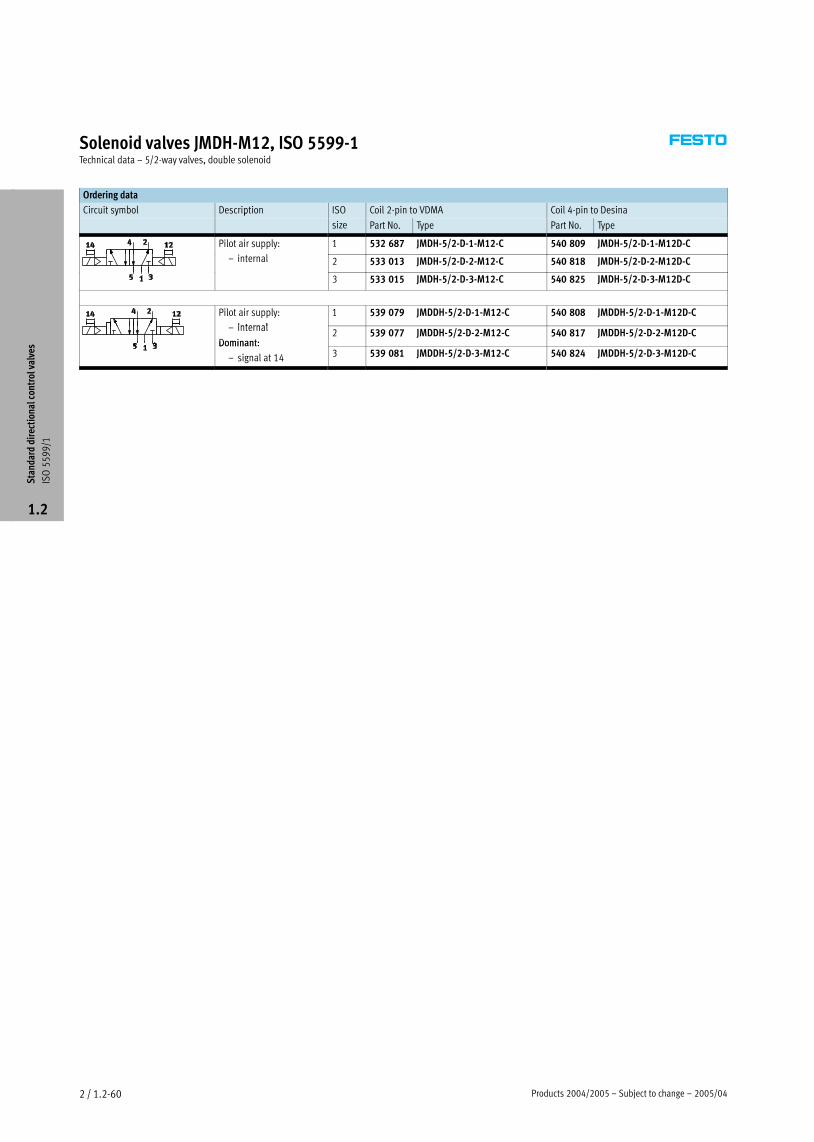
Solenoid valves JMDH−M12, ISO 5599−1Technical data – 5/2−way valves, double solenoid
Ordering data
Circuit symbol Description ISO Coil 2−pin to VDMA Coil 4−pin to Desinay p
size Part No. Type Part No. Type
Pilot air supply:
i l
1 532 687 JMDH−5/2−D−1−M12−C 540 809 JMDH−5/2−D−1−M12D−C
— internal 2 533 013 JMDH−5/2−D−2−M12−C 540 818 JMDH−5/2−D−2−M12D−C
3 533 015 JMDH−5/2−D−3−M12−C 540 825 JMDH−5/2−D−3−M12D−C
Pilot air supply:
internal
1 539 079 JMDDH−5/2−D−1−M12−C 540 808 JMDDH−5/2−D−1−M12D−C
— internal
Dominant:2 539 077 JMDDH−5/2−D−2−M12−C 540 817 JMDDH−5/2−D−2−M12D−C
Dominant:
— signal at 14 3 539 081 JMDDH−5/2−D−3−M12−C 540 824 JMDDH−5/2−D−3−M12D−C
Sta
ndar
d di
rect
iona
l con
trol
val
ves
ISO
55
99
/1
1.2

2005/04 – Subject to change – Products 2004/2005 2 / 1.2−61
Solenoid valves MDH−M12, ISO 5599−1Technical data – 5/3−way valves
−M− Flow rate
1,200 Ī 4,600 l/min
−P− Voltage
24 V DC
General technical data
ISO size 1 2 3
Valve function 5/3−way, monostable
Design Piston spool
Sealing principle Soft
Actuation type Electrical
Type of reset Mechanical spring
Type of actuation Piloted
Pilot air supply Internal
Direction of flow Non−reversible
Exhaust function Restrictable
Manual override Via tool accessory, detenting
Type of mounting Via through−holes
Mounting position Any
Nominal size [mm] 8 11 14.5
Standard nominal flow rate [l/min] 1,200 2,300 4,000 (B),
4 100 (G)4,100 (G),
4,600 (E)
Grid dimension [mm] 43 56 71
Pneumatic connection on sub−base G¼ Gy G½
Product weight [g] 580 880 1,120
Operating and environmental conditions
Operating medium Filtered compressed air, lubricated or unlubricated, grade of filtration 40�m
Operating pressure internal pilot air supply [bar] 3 Ī 10
Ambient temperature [°C] –10 Ī +50
Temperature of medium [°C] –10 Ī +50*
Valve response times
ISO size 1 2 3
On Off On Off On Off
with D solenoid coil with round plug M12x1
[ms] 25 55 35 70 36 90
Sta
ndar
d di
rect
iona
l con
trol
val
ves
ISO
55
99
/1
1.2

Products 2004/2005 – Subject to change – 2005/042 / 1.2−62
Solenoid valves MDH−M12, ISO 5599−1Technical data – 5/3−way valves
Electrical data
D solenoid coil with round plug
Electrical connection Type M12X1
Coil characteristics D.C. voltage [V DC] 21.6Ī26.4
Power [Watt] 2.7
Duty cycle % 100
Protection class to EN 60 529 IP65
Materials
Sectional view
1
1 Body Die−cast aluminium, polyacetate
– Seals Nitrile rubber
Sta
ndar
d di
rect
iona
l con
trol
val
ves
ISO
55
99
/1
1.2

2005/04 – Subject to change – Products 2004/2005 2 / 1.2−63
Solenoid valves MDH−M12, ISO 5599−1Technical data – 5/3−way valves
Dimensions Download CAD data � www.festo.com/en/engineering
1 Solenoid coil can be reposi-
tioned by 90° regardless of
manual override
2 Manual override facility
3 Captive mounting screws
5 LED display
6 Plug socket M12x1
Coil 2−pin to VDMA
Coil 4−pin to Desina
ISO size B1 B2 B3 B4 D1 H1 H2 H3 H4 L1 L2 L3 L4 L5 L6
1 42 28 6 30 M5 87.2 77.2 38 9 148 108.4 54.3 36 18 108.5
2 54 38 9 30 M6 97.2 87.2 48 9.5 165.8 158 79 48 24 126.3
3 65 48 12 30 M8 104.2 94.2 55 12 186.4 184 92 64 32 146.9
M12 plug – Pin allocation 2−pin to VDMA
3
2
4
1 1 Unused
2 Unused
3 com (–)
4 Signal (+)
M12 plug – Pin allocation 4−pin to Desina
1 connected with 2
2 connected with 1
3 com (–)
4 Signal (+)
Sta
ndar
d di
rect
iona
l con
trol
val
ves
ISO
55
99
/1
1.2

Products 2004/2005 – Subject to change – 2005/042 / 1.2−64
Solenoid valves MDH−M12, ISO 5599−1Technical data – 5/3−way valves
Ordering data
Circuit symbol Description ISO Coil 2−pin to VDMA Coil 4−pin to Desinay p
size Part No. Type Part No. Type
Normal position:
closed
1 525 307 MDH−5/3G−D−1−M12−C 540 806 MDH−5/3G−D−1−M12D−C
— closed
Pilot air supply:2 539078 MDH−5/3G−D−2−M12−C 540 815 MDH−5/3G−D−2−M12D−C
Pilot air supply:
— internal 3 539080 MDH−5/3G−D−3−M12−C 540 822 MDH−5/3G−D−3−M12D−C
Normal position:
exhausted
1 197 126 MDH−5/3E−D−1−M12−C 540 805 MDH−5/3E−D−1−M12D−C
— exhausted
Pilot air supply:2 533 016 MDH−5/3E−D−2−M12−C 540 814 MDH−5/3E−D−2−M12D−C
Pilot air supply:
— internal 3 533 017 MDH−5/3E−D−3−M12−C 540 821 MDH−5/3E−D−3−M12D−C
Normal position:
pressurised
1 533 005 MDH−5/3B−D−1−M12−C 540 807 MDH−5/3B−D−1−M12D−C
— pressurised
Pilot air supply:2 533 006 MDH−5/3B−D−2−M12−C 540 816 MDH−5/3B−D−2−M12D−C
Pilot air supply:
— internal 3 533 007 MDH−5/3B−D−3−M12−C 540 823 MDH−5/3B−D−3−M12D−C
Sta
ndar
d di
rect
iona
l con
trol
val
ves
ISO
55
99
/1
1.2

2004/10 – Subject to change – Products 2004/2005 2 / 1.2−65
Solenoid valves MDH, ISO 5599−1Technical data – 5/2−way valves
−M− Flow rate
−P− Voltage
24 V DC
42, 110, 230 V AC
General technical data
ISO size 4
Valve function 5/2−way, single solenoid
Constructional design Piston spool
Sealing principle Soft
Actuation type Electrical
Type of reset Pneumatic spring
Type of pilot control Piloted
Pilot air supply Internal
Direction of flow Non−reversible
Exhaust function With flow control
Manual override Via accessory, detenting
Type of mounting Via through−holes
Mounting position Any
Nominal size [mm] 18
Standard nominal flow rate [l/min] 6000
Grid dimension [mm] 82
Pneumatic connection on sub−base G¾
Product weight [g] 2600
Operating and environmental conditions
Operating medium Filtered compressed air, lubricated or unlubricated
Operating pressure Internal pilot air supply [bar] 3 Ī 16p g p
External pilot air supply [bar] –
Pilot pressure [bar] –
Ambient temperature [°C] –5 Ī +40
Temperature of medium [°C] –10 Ī +60*
Valve response times [ms]
D solenoid coil
On 120
Off 160
Sta
ndar
d di
rect
iona
l con
trol
val
ves
ISO
55
99
/1
1.2

Products 2004/2005 – Subject to change – 2004/102 / 1.2−66
Solenoid valves MDH, ISO 5599−1Technical data – 5/2−way valves
Electrical data
D solenoid coil
Electrical connection Design Plug, square design to EN 175301−803, type A
Operating voltage D.C. voltage [V DC] 24p g g
A.C. voltage [V AC] 42, 110, 230 (50 Ī 60 Hz)
Coil characteristics D.C. voltage [W] 6.8
A.C. voltage
42 V
[VA] Pull: 16.5
Hold: 12.2
A.C. voltage 110 V, 230 V [VA] Pull: 14.4
Hold: 10.5
Protection class to EN 60 529 IP65
Materials
Sectional view
1
1 Housing Anodised aluminium, polyacetate, brass
– Seals Nitrile rubber, polyurethane, polytetrafluoroethylene carbon
Sta
ndar
d di
rect
iona
l con
trol
val
ves
ISO
55
99
/1
1.2

2004/10 – Subject to change – Products 2004/2005 2 / 1.2−67
Solenoid valves MDH, ISO 5599−1Technical data – 5/2−way valves
Dimensions Download CAD data � www.festo.com/en/engineering
1 Wiring at plug socket to
EN 175301−803, type A
� 2 / 1.2−101
2 Manual override
3 Captive mounting screws
4 Solenoid coil can be
repositioned by 90° regardless
of manual override
Ordering data
Circuit symbol Solenoid coil Voltage ISO size Part No. Type
With D solenoid coil, 24 V DC 4 12 457 MDH−5/2−¾−D−4−24DC,
pneumatic reset, – 14 544 MDH−5/2−¾−D−41)p ,
internal pilot air supply Usable pilot valves:p pp y
24 V DC – 119 600 MDH−3/2−24DC
110 V AC – 119 601 MDH−3/2−110AC
230 V AC – 119 602 MDH−3/2−230AC
24 V DC/
42 V AC
– 119 603 MDH−3/2−24DC/42AC
1) Without pilot valve. The part number for the pilot valve must be quoted when ordering.
Order example: 14 544 MDH−5/2−¾−D−4−119 602
Sta
ndar
d di
rect
iona
l con
trol
val
ves
ISO
55
99
/1
1.2

Products 2004/2005 – Subject to change – 2004/102 / 1.2−68
Solenoid valves JMDH, ISO 5599−1Technical data – 5/2−way valves, double solenoid
−M− Flow rate
6000 l/min
−P− Voltage
24 V DC
42, 110, 230 V AC
General technical data
ISO size 4
Valve function 5/2−way, double solenoid
Constructional design Piston spool
Sealing principle Soft
Actuation type Electrical
Type of pilot control Piloted
Pilot air supply Internal
Direction of flow Non−reversible
Exhaust function With flow control
Manual override Via accessory, detenting
Type of mounting Via through−holes
Mounting position Any
Nominal size [mm] 18
Standard nominal flow rate [l/min] 6000
Grid dimension [mm] 82
Pneumatic connection on sub−base G¾
Product weight [g] 2600
Operating and environmental conditions
Operating medium Filtered compressed air, lubricated or unlubricated
Operating pressure Internal pilot air supply [bar] 2 Ī 16p g p
External pilot air supply [bar] –
Pilot pressure [bar] –
Ambient temperature [°C] –5 Ī +40
Temperature of medium [°C] –10 Ī +60*
Valve response times [ms]
With D solenoid coil
40
Sta
ndar
d di
rect
iona
l con
trol
val
ves
ISO
55
99
/1
1.2

2004/10 – Subject to change – Products 2004/2005 2 / 1.2−69
Solenoid valves JMDH, ISO 5599−1Technical data – 5/2−way valves, double solenoid
Electrical data
D solenoid coil
Electrical connection Plug, square design to EN 175301−803, type A
Operating voltage D.C. voltage [V DC] 24p g g
A.C. voltage [V AC] 42, 110, 230 (50 Ī 60 Hz)
Coil characteristics D.C. voltage [W] 6.8
A.C. voltage
42 V
[VA] Pull: 16.5
Hold: 12.2
A.C. voltage 110 V, 230 V [VA] Pull: 14.5
Hold: 10.5
Protection class to EN 60 529 IP65
Materials
Sectional view
1
1 Housing Anodised aluminium, polyacetate, brass
– Seals Nitrile rubber, polyurethane, polytetrafluoroethylene carbon
Sta
ndar
d di
rect
iona
l con
trol
val
ves
ISO
55
99
/1
1.2

Products 2004/2005 – Subject to change – 2004/102 / 1.2−70
Solenoid valves JMDH, ISO 5599−1Technical data – 5/2−way valves, double solenoid
Dimensions Download CAD data � www.festo.com/en/engineering
1 Wiring at plug socket to
EN 175301−803, type A
� 2 / 1.2−101
2 Manual override
3 Captive mounting screws
4 Solenoid coil can be
repositioned by 90° regardless
of manual override
Ordering data – Double solenoid valve
Circuit symbol Description Voltage ISO size Part No. Type
With D solenoid coil, 24 V DC 4 12 458 JMDH−5/2−¾−D−4−24DC,
internal pilot air supply – 14 545 JMDH−5/2−¾−D−41)p pp y
Usable pilot valves:
24 V DC – 119 600 MDH−3/2−24DC
110 V AC – 119 601 MDH−3/2−110AC
230 V AC – 119 602 MDH−3/2−230AC
24 V DC/
42 V AC
– 119 603 MDH−3/2−24DC/42AC
1) Without pilot valve. The part number for the pilot valve must be quoted when ordering.
Order example: 14 545 MDH−5/2−¾−D−4−119 602
Sta
ndar
d di
rect
iona
l con
trol
val
ves
ISO
55
99
/1
1.2

2004/10 – Subject to change – Products 2004/2005 2 / 1.2−71
Solenoid valves MDH, ISO 5599−1Technical data – 5/3−way valves
−M− Flow rate
4800 l/min
−P− Voltage
24 V DC
42, 110, 230 V AC
General technical data
ISO size 4
Valve function 5/3−way, single solenoid
Constructional design Piston spool
Sealing principle Soft
Actuation type Electrical
Type of reset Pneumatic spring
Type of pilot control Piloted
Pilot air supply Internal
Direction of flow Non−reversible
Exhaust function With flow control
Manual override Via accessory, detenting
Type of mounting Via through−holes
Mounting position Any
Nominal size [mm] 18
Standard nominal flow rate Closed [l/min] 4800
Exhausted [l/min] 4800
Grid dimension [mm] 82
Pneumatic connection on sub−base G¾
Product weight [g] 2600
Operating and environmental conditions
Operating medium Filtered compressed air, lubricated or unlubricated
Operating pressure Internal pilot air supply [bar] 3 Ī 16p g p
External pilot air supply [bar] –
Pilot pressure [bar] –
Ambient temperature [°C] – 5 Ī +40
Temperature of medium [°C] –10 Ī +60*
Valve response times [ms]
With D solenoid coil
On 85
Off 290
Sta
ndar
d di
rect
iona
l con
trol
val
ves
ISO
55
99
/1
1.2

Products 2004/2005 – Subject to change – 2004/102 / 1.2−72
Solenoid valves MDH, ISO 5599−1Technical data – 5/3−way valves
Electrical data
D solenoid coil
Electrical connection Plug, square design to EN 175301−803, type A
Operating voltage D.C. voltage [V DC] 24p g g
A.C. voltage [V AC] 42, 110, 230 (50 Ī 60 Hz)
Coil characteristics D.C. voltage [W] 6.8
A.C. voltage
42 V
[VA] Pull: 16.5
Hold: 12.2
A.C. voltage 110 V, 230 V [VA] Pull: 14.5
Hold: 10.5
Materials
Sectional view
1
1 Housing Anodised aluminium, polyacetate, brass
– Seals Nitrile rubber, polyurethane, polytetrafluoroethylene carbon
Sta
ndar
d di
rect
iona
l con
trol
val
ves
ISO
55
99
/1
1.2
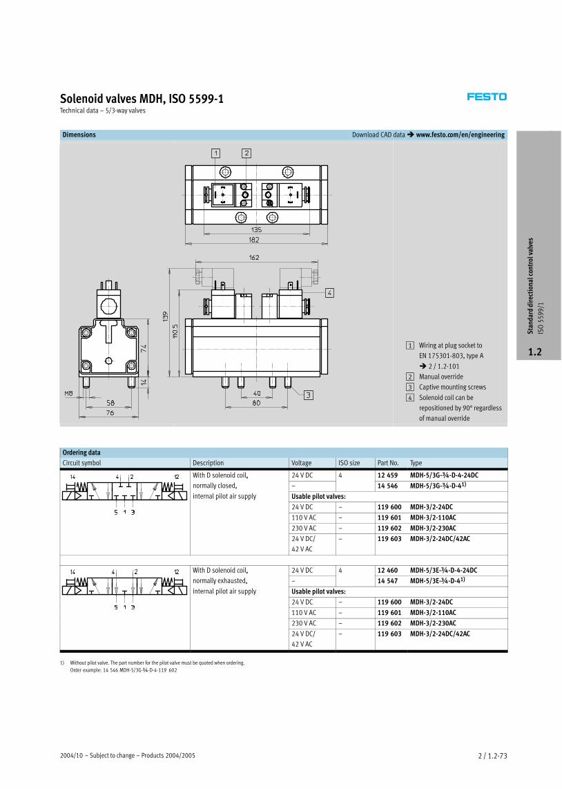
2004/10 – Subject to change – Products 2004/2005 2 / 1.2−73
Solenoid valves MDH, ISO 5599−1Technical data – 5/3−way valves
Dimensions Download CAD data � www.festo.com/en/engineering
1 Wiring at plug socket to
EN 175301−803, type A
� 2 / 1.2−101
2 Manual override
3 Captive mounting screws
4 Solenoid coil can be
repositioned by 90° regardless
of manual override
Ordering data
Circuit symbol Description Voltage ISO size Part No. Type
With D solenoid coil, 24 V DC 4 12 459 MDH−5/3G−¾−D−4−24DC,
normally closed, – 14 546 MDH−5/3G−¾−D−41)y ,
internal pilot air supply Usable pilot valves:p pp y
24 V DC – 119 600 MDH−3/2−24DC
110 V AC – 119 601 MDH−3/2−110AC
230 V AC – 119 602 MDH−3/2−230AC
24 V DC/
42 V AC
– 119 603 MDH−3/2−24DC/42AC
With D solenoid coil, 24 V DC 4 12 460 MDH−5/3E−¾−D−4−24DC,
normally exhausted, – 14 547 MDH−5/3E−¾−D−41)y ,
internal pilot air supply Usable pilot valves:p pp y
24 V DC – 119 600 MDH−3/2−24DC
110 V AC – 119 601 MDH−3/2−110AC
230 V AC – 119 602 MDH−3/2−230AC
24 V DC/
42 V AC
– 119 603 MDH−3/2−24DC/42AC
1) Without pilot valve. The part number for the pilot valve must be quoted when ordering.
Order example: 14 546 MDH−5/3G−¾−D−4−119 602
Sta
ndar
d di
rect
iona
l con
trol
val
ves
ISO
55
99
/1
1.2

Products 2004/2005 – Subject to change – 2003/102 / 1.2−74
Pneumatic valves, ISO 5599−1Type code
VL � 5/3 G � D−1 � � C
Type
VL Single pilot
J Double pilot
JD Double pilot, with dominant signal
Valve function
5/2 5/2−way valve
5/3 5/3−way valve
Normal position
G Closed
E Exhausted
B Pressurised
Size
D−1 ISO size 1
D−2 ISO size 2
D−3 ISO size 3
¾−D−4 ISO size 4
Type of reset
FR Mechanical spring
Pneumatic spring
Generation
C Series C
Sta
ndar
d di
rect
iona
l con
trol
val
ves
ISO
55
99
/1
1.2

2004/10 – Subject to change – Products 2004/2005 2 / 1.2−75
Pneumatic valves, ISO 5599−1Peripherals overview
Individual mounting
31
2
3
1
4
Variants
J−5/Ī−¾−D−4,
VL−5/Ī−¾−D−4
Accessories
Brief description � Page
1 Push−in fitting
QS
For connecting compressed air tubing with standard O.D. Volume 3
2 Individual sub−base
NAS/NAU
NAS – With lateral ports
NAU – With ports underneath
2 / 1.2−88
3 Silencer For fitting in exhaust ports Volume 3
4 Pneumatic valve Port pattern to ISO 5599−1 2 / 1.2−6
Port pattern on sub−base to ISO 5599−1
Defined interfaces between valve and sub−base
ISO 1 ISO 2 ISO 3 ISO 4
aD
5
4
1
2
3
aB
Sta
ndar
d di
rect
iona
l con
trol
val
ves
ISO
55
99
/1
1.2

Products 2004/2005 – Subject to change – 2004/102 / 1.2−76
Pneumatic valves, ISO 5599−1Peripherals overview
Manifold mounting
1
2
3
4
5
6
7
8
9
9
aA
aJ
9
aB
4
12
2
2
8
8
8
Sta
ndar
d di
rect
iona
l con
trol
val
ves
ISO
55
99
/1
1.2

2004/10 – Subject to change – Products 2004/2005 2 / 1.2−77
Pneumatic valves, ISO 5599−1Peripherals overview
Accessories
Brief description � Page
1 End plate kit
NEV
For sealing the manifold sub−bases 2 / 1.2−91
2 Push−in fitting
QS
For connecting compressed air tubing with standard O.D. Volume 3
3 Angle connection block
NAW
For routing ports 2 and 4 to the front 2 / 1.2−90
4 Manifold sub−base
NAV
With ports 2 and 4 on the bottom 2 / 1.2−90
5 Isolating disc
NSC
For sealing the common lines 1, 3, 5 between end plates and manifold sub−bases or between
2 manifold sub−bases, e.g. for different working pressures
2 / 1.2−92
6 Intermediate plate
NZV
For connecting manifold sub−bases of different sizes 2 / 1.2−94
7 Manifold sub−base for angle connection
NAVW
With ports 2 and 4 either on the bottom or the front 2 / 1.2−91
8 Silencer For fitting in exhaust ports Volume 3
9 Pneumatic valve Port pattern to ISO 5599−1 2 / 1.2−6
aJ Blanking plate
NDV
For sealing unused manifold sub−bases 2 / 1.2−92
aA Throttle plate for ISO size 1, 2 and 3
GRO
With integrated exhaust air restrictors at port 3 and 5. The throttle plate is mounted between
the valve and the individual sub−base/manifold sub−base
2 / 1.2−95
aB Intermediate pressure regulator plate
for ISO size 1, 2 and 3
LR−ZP
For regulating the pressure from 0 to 12 bar according to the supply pressure.
The intermediate pressure regulator plate is mounted between the valve and the individual
sub−base/manifold sub−base
2 / 1.2−96
Port pattern on sub−base to ISO 5599−1
Defined interfaces between valve and sub−base
ISO 1 ISO 2 ISO 3 ISO 4
aD
5
4
1
2
3
aB
Sta
ndar
d di
rect
iona
l con
trol
val
ves
ISO
55
99
/1
1.2

Products 2004/2005 – Subject to change – 2003/102 / 1.2−78
Pneumatic valves VL, ISO 5599−1Technical data – 5/2−way valves
−M− Flow rate
1200 Ī 6000 l/min
General technical data
ISO size 1 2 3 4
Valve function 5/2−way, single pilot
Constructional design Piston spool
Sealing principle Soft
Actuation type Pneumatic
Type of reset Mechanical or pneumatic spring
Type of pilot control Direct
Direction of flow Non−reversible
Exhaust function With flow control
Manual override None
Type of mounting Via through−holes
Mounting position Any
Nominal size [mm] 8 11 14.5 18
Standard nominal flow rate [l/min] 1200 2300 4500 6000
Grid dimension [mm] 43 56 71 82
Pneumatic connection on sub−base 1, 2, 3, 4, 5 G¼ Gy G½ G¾
12, 14 Gx Gx Gx Gx
Product weight [g] 290 550 810 1800
Noise level [dB (A)] 85
Operating and environmental conditions
ISO size 1, 2, 3 4
Type of reset Pneumatic Mechanical Pneumatic
Operating medium Filtered compressed air, lubricated or unlubricated
Vacuum
Operating pressure [bar] 2 Ī 16 –0.9 Ī 16 –0.9 Ī +16
Pilot pressure [bar] 2 Ī 16 3 Ī 16 3 Ī 16
Ambient temperature [°C] –10 Ī +60
Temperature of medium [°C] –10 Ī +60*
Sta
ndar
d di
rect
iona
l con
trol
val
ves
ISO
55
99
/1
1.2

2003/10 – Subject to change – Products 2004/2005 2 / 1.2−79
Pneumatic valves VL, ISO 5599−1Technical data – 5/2−way valves
Valve response times
ISO size 1 2 3 4
Type of reset Pneumatic Mechanical Pneumatic Mechanical Pneumatic Mechanical Pneumatic Mechanical
On 9 6 23 11 29 13 25 –
Off 18 23 39 39 36 43 90 –
Materials
Sectional view (ISO size 1, 2, 3)
1
ISO size 1, 2, 3 4
1 Housing Die−cast aluminium, polyacetate Anodised aluminium, brass, polyurethane
– Seals Nitrile rubber Nitrile rubber, polytetrafluoroethylene carbon
Sta
ndar
d di
rect
iona
l con
trol
val
ves
ISO
55
99
/1
1.2

Products 2004/2005 – Subject to change – 2003/102 / 1.2−80
Pneumatic valves VL, ISO 5599−1Technical data – 5/2−way valves
Dimensions Download CAD data � www.festo.com/en/engineering
ISO size 1, 2, 3
3 Captive mounting screws
Type B1 B2 B3 D1 H3 H4 H5 L2 L3 L4 L5
ISO size 1
VL−5/2−Ī 42 28 6 M5 38 9 46.5 87.6 43.8 36 18
VL−5/2−Ī−FR
5 3 9 5
98
3 3
ISO size 2
VL−5/2−Ī 54 38 9 M6 48 9.5 56.5 123.4 61.7 48 24
VL−5/2−Ī−FR
5 3 9 9 5 5 5
140.7
7
ISO size 3
VL−5/2−Ī 65 48 12 M8 55 12 63.5 145.4 72.7 64 32
VL−5/2−Ī−FR
5 55 3 5
164.7
7 7 3
Sta
ndar
d di
rect
iona
l con
trol
val
ves
ISO
55
99
/1
1.2

2003/10 – Subject to change – Products 2004/2005 2 / 1.2−81
Pneumatic valves VL, ISO 5599−1Technical data – 5/2−way valves
Dimensions Download CAD data � www.festo.com/en/engineering
ISO size 4
3 Captive mounting screws
Ordering data
Circuit symbol Description ISO size Part No. Type
Pneumatic reset 1 151 009 VL−5/2−D−1−C
2 151 845 VL−5/2−D−2−C
3 151 864 VL−5/2−D−3−C
4 12 461 VL−5/2−¾−D−4
Mechanical reset 1 151 014 VL−5/2−D−1−FR−C
2 151 844 VL−5/2−D−2−FR−C
3 151 863 VL−5/2−D−3−FR−C
Sta
ndar
d di
rect
iona
l con
trol
val
ves
ISO
55
99
/1
1.2

Products 2004/2005 – Subject to change – 2003/102 / 1.2−82
Pneumatic valves J, ISO 5599−1Technical data – 5/2−way valves, double pilot
−M− Flow rate
1200 Ī 6000 l/min
General technical data
ISO size 1 2 3 4
Valve function 5/2−way, double pilot
Constructional design Piston spool
Sealing principle Soft
Actuation type Pneumatic
Type of pilot control Direct
Direction of flow Reversible
Exhaust function With flow control
Manual override None
Type of mounting Via through−holes
Mounting position Any
Nominal size [mm] 8 11 14.5 18
Standard nominal flow rate [l/min] 1200 2300 4500 6000
Grid dimension [mm] 43 56 71 82
Pneumatic connection on sub−base 1, 2, 3, 4, 5 G¼ Gy G½ G¾
12, 14 Gx Gx Gx Gx
Product weight [g] 290 550 810 1800
Noise level [dB (A)] 85
Operating and environmental conditions
Operating medium Filtered compressed air, lubricated or unlubricated
Vacuum
Operating pressure [bar] –0.9 Ī 16
Pilot pressure [bar] 2 Ī 16
Ambient temperature [°C] –10 Ī +60
Temperature of medium [°C] –10 Ī +60*
Valve response times [ms]
ISO size 1 2, 3 4
Dominant signal at 14 Dominant signal at 14
6 6/4 8 8 20
Sta
ndar
d di
rect
iona
l con
trol
val
ves
ISO
55
99
/1
1.2

2003/10 – Subject to change – Products 2004/2005 2 / 1.2−83
Pneumatic valves J, ISO 5599−1Technical data – 5/2−way valves, double pilot
Materials
Sectional view (ISO size 4)
1
ISO size 1, 2, 3 4
1 Housing Die−cast aluminium, polyacetate Anodised aluminium, brass, polyurethane
– Seals Nitrile rubber Nitrile rubber, polytetrafluoroethylene carbon
Dimensions Download CAD data � www.festo.com/en/engineering
ISO size 1, 2, 3
3 Captive mounting screws
ISO size B1 B2 B3 D1 H3 H4 H5 L2 L3 L4 L5
1 42 28 6 M5 38 9 46.5 87.6 43.8 36 18
2 54 38 9 M6 48 9.5 56.5 123.4 61.7 48 24
3 65 48 12 M8 55 12 63.5 145.4 72.7 64 32
Sta
ndar
d di
rect
iona
l con
trol
val
ves
ISO
55
99
/1
1.2

Products 2004/2005 – Subject to change – 2003/102 / 1.2−84
Pneumatic valves J, ISO 5599−1Technical data – 5/2−way valves, double pilot
Dimensions Download CAD data � www.festo.com/en/engineering
ISO size 4
3 Captive mounting screws
Ordering data
Circuit symbol Description ISO size Part No. Type
1 151 007 J−5/2−D−1−C
2 151 846 J−5/2−D−2−C
3 151 865 J−5/2−D−3−C
4 12 462 J−5/2−¾−D−4
With dominant signal at 14 1 151 008 JD−5/2−D−1−C
2 151 847 JD−5/2−D−2−C
3 151 866 JD−5/2−D−3−C
Sta
ndar
d di
rect
iona
l con
trol
val
ves
ISO
55
99
/1
1.2

2003/10 – Subject to change – Products 2004/2005 2 / 1.2−85
Pneumatic valves VL, ISO 5599−1Technical data – 5/3−way valves
−M− Flow rate
1200 Ī 6000 l/min
General technical data
ISO size 1 2 3 4
Valve function 5/3−way, single pilot
Constructional design Piston spool
Sealing principle Soft
Actuation type Pneumatic
Type of reset Mechanical spring
Type of pilot control Direct
Pilot air supply Internal
Direction of flow Reversible
Exhaust function With flow control
Manual override None
Type of mounting Via through−holes
Mounting position Any
Nominal size [mm] 8 11 14.5 18
Standard nominal flow rate Closed [l/min] 1200 2300 4100 6000
Exhausted [l/min]
3
4600 4800
Pressurised [l/min] 4100 –
Grid dimension [mm] 43 56 71 82
Pneumatic connection on sub−base 1, 2, 3, 4, 5 G¼ Gy G½ G¾
12, 14 Gx Gx Gx Gx
Product weight [g] 320 825 910 2000
Noise level [dB (A)] 85
Operating and environmental conditions
Operating medium Filtered compressed air, lubricated or unlubricated
Vacuum
Operating pressure [bar] –0.9 Ī +16
Pilot pressure [bar] 3 Ī 16
Ambient temperature [°C] –10 Ī +60
Temperature of medium [°C] –10 Ī +60*
Valve response times
ISO size 1 2 3 4
On Off On Off On Off On Off
Closed 7 45 15 56 17 61 40 130
Exhausted 7 45 16 59 18 63 40 130
Pressurised 7 45 15 57 16 60 – –
Sta
ndar
d di
rect
iona
l con
trol
val
ves
ISO
55
99
/1
1.2
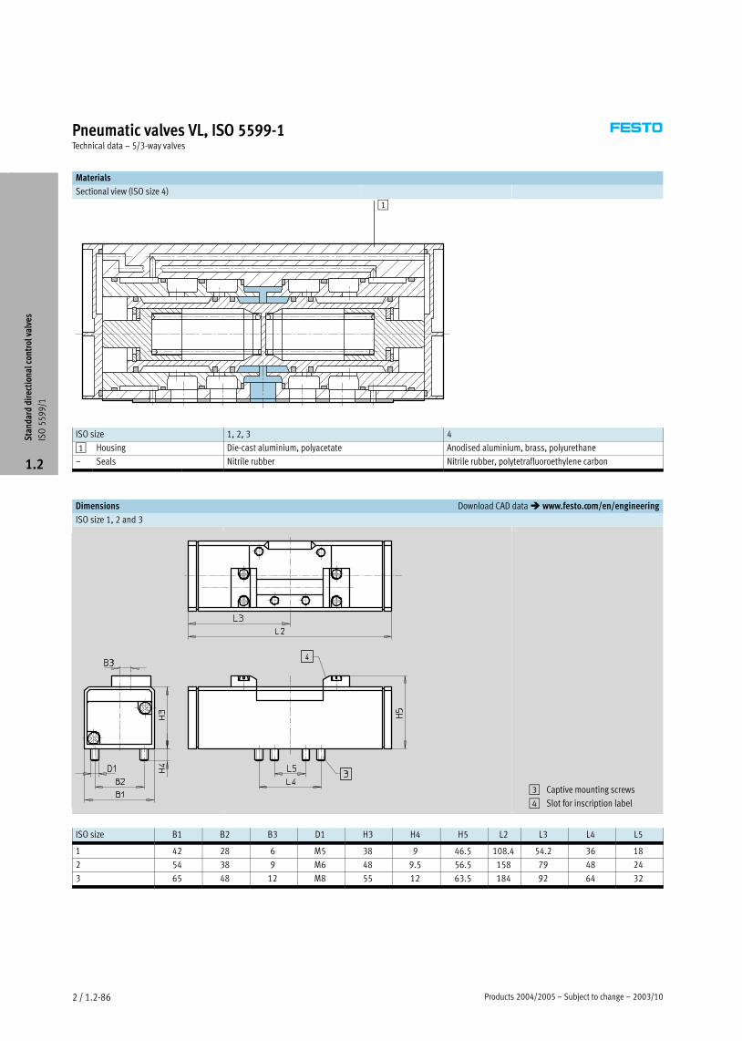
Products 2004/2005 – Subject to change – 2003/102 / 1.2−86
Pneumatic valves VL, ISO 5599−1Technical data – 5/3−way valves
Materials
Sectional view (ISO size 4)
1
ISO size 1, 2, 3 4
1 Housing Die−cast aluminium, polyacetate Anodised aluminium, brass, polyurethane
– Seals Nitrile rubber Nitrile rubber, polytetrafluoroethylene carbon
Dimensions Download CAD data � www.festo.com/en/engineering
ISO size 1, 2 and 3
3 Captive mounting screws
4 Slot for inscription label
ISO size B1 B2 B3 D1 H3 H4 H5 L2 L3 L4 L5
1 42 28 6 M5 38 9 46.5 108.4 54.2 36 18
2 54 38 9 M6 48 9.5 56.5 158 79 48 24
3 65 48 12 M8 55 12 63.5 184 92 64 32
Sta
ndar
d di
rect
iona
l con
trol
val
ves
ISO
55
99
/1
1.2

2003/10 – Subject to change – Products 2004/2005 2 / 1.2−87
Pneumatic valves VL, ISO 5599−1Technical data – 5/3−way valves
Dimensions Download CAD data � www.festo.com/en/engineering
ISO size 4
3 Captive mounting screws
Ordering data
Circuit symbol Description ISO size Part No. Type
Normally closed, 1 151 010 VL−5/3G−D−1−Cy ,
mechanical reset 2 151 848 VL−5/3G−D−2−C
3 151 867 VL−5/3G−D−3−C
4 12 463 VL−5/3G−¾−D−4
Normally exhausted, 1 151 011 VL−5/3E−D−1−Cy ,
mechanical reset 2 151 849 VL−5/3E−D−2−C
3 151 868 VL−5/3E−D−3−C
4 12 464 VL−5/3E−¾−D−4
Normally pressurised, 1 151 012 VL−5/3B−D−1−Cy p ,
mechanical reset 2 151 850 VL−5/3B−D−2−C
3 151 869 VL−5/3B−D−3−C
Sta
ndar
d di
rect
iona
l con
trol
val
ves
ISO
55
99
/1
1.2

Products 2004/2005 – Subject to change – 2005/042 / 1.2−88
Solenoid/pneumatic valves, ISO 5599−1Accessories
Individual sub−base
NAS
Lateral ports
Material:
Size 1, 2, 3
Die−cast aluminium
Size 4
Anodised aluminium
Dimensions and ordering data
ISO size B1 D1 D2 D3 H1 H2 H4 H5 H6 L1 L2 L3 L4 L5 Weight Part No. Type
∅ [g]
1 48 G¼ Gx 5.5 32 10 9 20.3 20.3 110 98 23 60 46 190 9 484 NAS−¼−1A−ISO1)
2 57 Gy Gx 6.6 40 13 9 25 25 124 112 27 71 54 300 11 310 NAS−y−2A−ISO1)
3 71 G½ Gx 6.6 32 18 9 16 16 149 136 32 91 64 360 10 336 NAS½−3A−ISO1)
4 85 G¾ Gx 9 42 19 9 21 21 186 170 42 111 84 1260 152 813 NAS−¾−4A−ISO
1) Free of copper, PTFE and silicone
General technical data
ISO size 1 2 3 4
Type of mounting 2 through−holes in housing
Pneumatic connection 1, 2, 3, 4, 5 G¼ Gy G½ G¾
12, 14 Gx Gx Gx Gx
Sta
ndar
d di
rect
iona
l con
trol
val
ves
ISO
55
99
/1
1.2

2005/04 – Subject to change – Products 2004/2005 2 / 1.2−89
Solenoid/pneumatic valves, ISO 5599−1Accessories
Individual sub−base
NAU
Ports underneath
Material:
Size 1, 2, 3
Die−cast aluminium
Size 4
Anodised aluminium
Dimensions and ordering data
ISO size B1 D1 D2 D3 H1 H2 H3 H4 H5 L1 L2 L3 L4 L5 Weight Part No. Type
∅ [g]
1 46 G¼ Gx 5.5 30 10 5 7.5 20 110 98 23 60.7 46 280 9 485 NAU−¼−1B−ISO1)
2 56 Gy Gx 6.6 35 13 6.5 8.3 24 124 112 27 70 54 450 11 416 NAU−y−2B−ISO1)
3 71 G½ Gx 6.6 32 18 9 10 30 149 136 32 90 66 660 10 337 NAU½−3B−ISO1)
4 85 G¾ Gx 9 28 19 9.5 12 37 186 170 42 111 84 1080 152 814 NAU−¾−4B−ISO
1) Free of copper, PTFE and silicone
General technical data
ISO size 1 2 3 4
Type of mounting 2 through−holes in housing
Pneumatic connection 1, 2, 3, 4, 5 G¼ Gy G½ G¾
12, 14 Gx Gx Gx Gx
Sta
ndar
d di
rect
iona
l con
trol
val
ves
ISO
55
99
/1
1.2

Products 2004/2005 – Subject to change – 2005/042 / 1.2−90
Solenoid/pneumatic valves, ISO 5599−1Accessories
Manifold sub−base NAV
Ports underneath
Material:
Size 1, 2, 3
Die−cast aluminium
Size 4
Anodised aluminium
Ordering data
ISO size Pneumatic connection Weight Part No. Type
1, 2, 3, 4, 5 12, 14 [g]
1 G¼ Gx 240 10 173 NAV−¼−1C−ISO
2 Gy Gx 400 11 305 NAV−y−2C−ISO
3 G½ Gx 700 10 175 NAV−½−3C−ISO
4 G¾ Gx 1400 11 139 NAV−¾−4C−ISO
Dimensions � 2 / 1.2−93
Angle connection block NAW
Ports at side and underneath
Material:
Size 1, 2, 3
Die−cast aluminium
Size 4
Anodised aluminium
Ordering data
ISO size Pneumatic connection Weight Part No. Type
1, 2, 3, 4, 5 12, 14 [g]
1 G¼ Gx 360 11 304 NAW−¼−1E−ISO1)
2 Gy Gx 600 11 307 NAW−y−2E−ISO1)
3 G½ Gx 920 11 309 NAW−½−3E−ISO1)
4 G¾ Gx 1550 11 141 NAW−¾−4E−ISO
Dimensions � 2 / 1.2−93
1) Free of copper, PTFE and silicone
Sta
ndar
d di
rect
iona
l con
trol
val
ves
ISO
55
99
/1
1.2

2005/04 – Subject to change – Products 2004/2005 2 / 1.2−91
Solenoid/pneumatic valves, ISO 5599−1Accessories
Manifold sub−base for angle
connection NAVW
Ports at side and underneath
Material:
Size 1, 2, 3
Die−cast aluminium
Size 4
Anodised aluminium
Ordering data
ISO size Pneumatic connection Weight Part No. Type
1, 2, 3, 4, 5 12, 14 [g]
1 G¼ Gx 320 152 789 NAVW−¼−1−ISO
2 Gy Gx 550 152 790 NAVW−y−2−ISO
3 G½ Gx 1020 152 791 NAVW−½−3−ISO
Dimensions � 2 / 1.2−93
End plate kit NEV
Material:
Size 1, 2, 3
Die−cast aluminium
Size 4
Anodised aluminium
Ordering data
ISO size Pneumatic connection Weight Part No. Type
1, 2, 3, 4, 5 12, 14 [g]
1 Gy – 280 10 174 NEV−1DA/DB−ISO1)
2 G½ – 450 11 306 NEV−2DA/DB−ISO1)
3 G1 – 760 10 176 NEV−3DA/DB−ISO1)
4 G1 – 1390 11 140 NEV−4DA/DB−ISO
Dimensions � 2 / 1.2−93
1) Free of copper, PTFE and silicone
Sta
ndar
d di
rect
iona
l con
trol
val
ves
ISO
55
99
/1
1.2

Products 2004/2005 – Subject to change – 2005/042 / 1.2−92
Solenoid/pneumatic valves, ISO 5599−1Accessories
Blanking plate NDV
Material:
Size 1, 2, 3
Steel
Size 4
Wrought aluminium alloy
Ordering data
ISO size Weight Part No. Type
[g]
1 113 9 489 NDV−1−ISO
2 166 11 308 NDV−2−ISO
3 314 10 340 NDV−3−ISO
4 1480 11 142 NDV−4−ISO
Dimensions � 2 / 1.2−93
Isolating disc NSC
Material:
Wrought aluminium alloy
Ordering data
ISO size Pneumatic connection Weight Part No. Type
1, 2, 3 12, 14 [g]
1 ¼ – 6 11 550 NSC−¼−1−ISO1)
2 y – 9.2 11 908 NSC−y−2−ISO1)
3 ½ – 20 11 551 NSC−½−3−ISO1)
4 ¾ – 24 11 699 NSC−¾−4−ISO
Dimensions � 2 / 1.2−93
1) Free of copper, PTFE and silicone
Sta
ndar
d di
rect
iona
l con
trol
val
ves
ISO
55
99
/1
1.2

2005/04 – Subject to change – Products 2004/2005 2 / 1.2−93
Solenoid/pneumatic valves, ISO 5599−1Accessories
Dimensions – Manifold mounting Download CAD data � www.festo.com/en/engineering
1 Left−hand end plate
2 Manifold sub−base NAV
3 Blanking plate NDV
4 Right−hand end plate
5 Angle connection block NAW
6 Port pattern to ISO 5599−1
7 Manifold sub−base for angle
connection NAVW
8 Isolating disc NSC
ISO size B1 B2 B3 B4 B5 B6 B7 B8 B9 D1 D2 D3 D4 D5 D6
∅ ∅ ∅
1 43 22 42 40 11 7.5 1.5 4 21.6 G¼ Gy Gx 10 5.5 7
2 56 26 55 50 13 6 5 6 27 Gy G½ Gx 11 6.6 9
3 71 30 70 70 15 8 6 6 35.5 G½ G1 Gx 15 9 12
4 82 30 80 80 15 9 8 – – G¾ G1 Gx 15 9 12
ISO size H1 H2 H3 H4 H5 H6 H7 L1 L2 L3 L4 L5 L6 L7 T1
1 81 46 44 50.5 12.5 37 5 110 95 80 28 26 11 11 5.7
2 85 47 45 60 15 40 5 135 115 96 35 30 15 14 6.8
3 99 56 54 66 17.5 45 5 190 168 120 52 38 19 19 9
4 120 58 55 – – 65 5 215 184 – 56 52 – – 9
Sta
ndar
d di
rect
iona
l con
trol
val
ves
ISO
55
99
/1
1.2

Products 2004/2005 – Subject to change – 2005/042 / 1.2−94
Solenoid/pneumatic valves, ISO 5599−1Accessories
Intermediate plate NZV
for connecting manifold sub−bases of
different sizes
Material:
Die−cast aluminium, anodised
Free of copper, PTFE and silicone
Dimensions Download CAD data � www.festo.com/en/engineering
Intermediate plates NZV – ISO size 1, 2, 3
1 Left−hand end plate
ISO size 2
2 Manifold sub−base
ISO size 2
3 Intermediate plate
NZV−1−2
4 Manifold sub−base
ISO size 1
5 Right−hand end plate
ISO size 1
NZV−1−2 NZV−3−2/1
Ordering data
Weight Part No. Type
[g]
For manifold sub−bases ISO size 1 and 2
393 164 940 NZV−1−2
For manifold sub−bases ISO size 1 and 3 or size 2 and 3
473 12 911 NZV−3−2/1
Sta
ndar
d di
rect
iona
l con
trol
val
ves
ISO
55
99
/1
1.2

2005/04 – Subject to change – Products 2004/2005 2 / 1.2−95
Solenoid/pneumatic valves, ISO 5599−1Accessories
Throttle plates GRO
Exhaust air restrictor for 3 and 5
Material:
Anodised aluminium, brass
Standard nominal flow rate qnN as a function of the turns n of the adjusting screw
GRO−ZP−1−ISO−B GRO−ZP−2−ISO−B GRO−ZP−3−ISO−B
n
qnN
[l/m
in]
n
qnN
[l/m
in]
qnN
[l/m
in]
n
Dimensions Download CAD data � www.festo.com/en/engineering
1 Regulating screw for restrictor
2 Captive mounting screws
Dimensions and ordering data
ISO size D1 B1 B2 H1 H2 H3 L1 L2 L3 L4 Weight Part No. Type
[g]
1 M5 42 28 25 6.5 12.5 77 36 18 6 230 151 705 GRO−ZP−1−ISO−B
2 M6 54 38 29 9.5 14.5 100 48 24 6.3 440 151 706 GRO−ZP−2−ISO−B
3 M8 70 48 33 12 16.5 132 64 32 7 850 151 707 GRO−ZP−3−ISO−B
Sta
ndar
d di
rect
iona
l con
trol
val
ves
ISO
55
99
/1
1.2

Products 2004/2005 – Subject to change – 2005/042 / 1.2−96
Solenoid/pneumatic valves, ISO 5599−1Accessories
Intermediate pressure regulator
plate
LR−ZP
Material:
Housing:
Die−cast aluminium, steel
Seals:
Nitrile rubber
Flow rate qn as a function of the output pressure p2
LR−ZP−A−D−1, LR−ZP−B−1,
LR−ZP−A/B−1
LR−ZP−P−D−1 LR−ZP−A−D−2, LR−ZP−B−2,
LR−ZP−A/B−2
LR−ZP−P−D−2
qn [l/min]
p2 [b
ar]
p2 [b
ar]
qn [l/min] qn [l/min]
p2 [b
ar]
qn [l/min]p2
[bar
]
LR−ZP−A−D−3, LR−ZP−B−3,
LR−ZP−A/B−3
LR−ZP−P−D−3
qn [l/min]
p2 [b
ar]
qn [l/min]
p2 [b
ar]
Pressure regulation
Port 1 regulated Port 2 regulated
Port 4 regulated Ports 2 and 4 regulated
Sta
ndar
d di
rect
iona
l con
trol
val
ves
ISO
55
99
/1
1.2
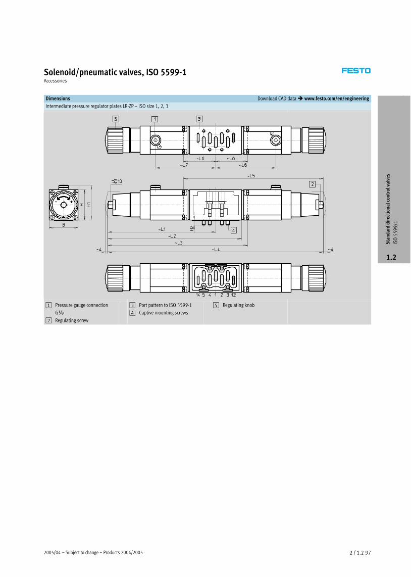
2005/04 – Subject to change – Products 2004/2005 2 / 1.2−97
Solenoid/pneumatic valves, ISO 5599−1Accessories
Dimensions Download CAD data � www.festo.com/en/engineering
Intermediate pressure regulator plates LR−ZP – ISO size 1, 2, 3
1 Pressure gauge connection
Gx
2 Regulating screw
3 Port pattern to ISO 5599−1
4 Captive mounting screws
5 Regulating knob
Sta
ndar
d di
rect
iona
l con
trol
val
ves
ISO
55
99
/1
1.2

Products 2004/2005 – Subject to change – 2005/042 / 1.2−98
Solenoid/pneumatic valves, ISO 5599−1Accessories
Dimensions and ordering data
Regulated port B H H1 H2 L1 L2 L3 L4 L5 L6 L7 L8 Weight Part No. Typeg p
[g]
ISO size 1
1 42.6 45 52 8 161 – 209 – – 48 90 – 520 35 966 LR−ZP−P−D−15 5 9 9 5
165 859 LR−ZP−P−D−1−CT1)
2 – – – – 209 48 – 90 520 35 424 LR−ZP−B−D−19 9 5
165 856 LR−ZP−B−D−1−CT1)
4 161 – – 322 – – 90 90 520 35 969 LR−ZP−A−D−13 9 9 5
165 850 LR−ZP−A−D−1−CT1)
2, 4 161 200 – – – – 90 – 840 35 427 LR−ZP−A/B−D−1, 9
165 853 LR−ZP−A/B−D−1−CT1)
ISO size 2
1 54 58 62.5 10 188 – 247 – – – 105.5 – 960 35 967 LR−ZP−P−D−25 5 5 7 5 5 9
165 860 LR−ZP−P−D−2−CT1)
2 – – – – 247 59 – 105.5 960 35 425 LR−ZP−B−D−27 59 5 5 9
165 857 LR−ZP−B−D−2−CT1)
4 188 – – 376 – – 105.5 105.5 960 35 970 LR−ZP−A−D−237 5 5 5 5 9
165 851 LR−ZP−A−D−2−CT1)
2, 4 188 233 – – – – 105.5 – 1490 35 428 LR−ZP−A/B−D−2, 33 5 5 9
165 854 LR−ZP−A/B−D−2−CT1)
ISO size 3
1 70 63 65 14 201.5 – 274 – – – 119 – 1220 35 968 LR−ZP−P−D−37 3 5 5 7 9
165 861 LR−ZP−P−D−3−CT1)
2 – – – 274 72.5 – 119 1220 35 426 LR−ZP−B−D−37 7 5 9
165 858 LR−ZP−B−D−3−CT1)
4 – – 403 – – 119 119 1220 35 971 LR−ZP−A−D−33 9 9
165 852 LR−ZP−A−D−3−CT1)
2, 4 260 – – – – 119 – 1770 35 429 LR−ZP−A/B−D−3, 9 77
165 855 LR−ZP−A/B−D−3−CT1)
1) Free of copper, PTFE and silicone
Ordering data – Pressure gauge for intermediate pressure regulator plates LR−ZP
ISO size Weight Part No. Type
[g]
1, 2, 3 64.5 345 395 MA−40−16−x
Sta
ndar
d di
rect
iona
l con
trol
val
ves
ISO
55
99
/1
1.2

2005/04 – Subject to change – Products 2004/2005 2 / 1.2−99
Solenoid/pneumatic valves, ISO 5599−1Accessories
Manual override tool
AHB
Material:
Polymer
Ordering data
For valve Weight Part No. Type
[g]
MEBH 5 157 601 AHB−MEB
MN1H/MFH 10 157 651 AHB−MD/MF/MV
Inscription labels
IBS−9x17
Material:
Polymer
Ordering data
Part No. Type
Inscription label for valves
(24 in frames included in scope of delivery)
161 937 IBS−9x17
Sta
ndar
d di
rect
iona
l con
trol
val
ves
ISO
55
99
/1
1.2
Core Range

Products 2004/2005 – Subject to change – 2005/042 / 1.2−100
Solenoid/pneumatic valves, ISO 5599−1Accessories
Ordering data
Part No. Type
Push−in fittings QS
��Volume 3
� www.festo.com
Silencers
��Volume 3
� www.festo.com
Ordering data – Solenoid coils Technical data � NO TAG
Ordering data – Solenoid coils Technical data � www.festo.com
Voltage Cable length Part No. Type
[m]
F solenoid coils for valves MFH, JMFH
12 V DC – 34 410 MSFG−12DC−OD
24 V DC and 42 V AC, 50 Ī 60 Hz – 34 411 MSFG−24DC/42AC−OD
42 V DC – 34 413 MSFG−42DC−OD
24 V AC – 34 415 MSFG−24AC−OD
48 V AC, 50 Ī 60 Hz – 34 418 MSFW−48AC−OD
110 V AC, 50 Ī 60 Hz and 120 V AC, 60 Hz – 34 420 MSFW−110AC−OD
230 V AC, 50 Ī 60 Hz and 240 V AC, 60 Hz – 34 422 MSFW−230AC−OD
240 V AC, 50 Ī 60 Hz – 34 424 MSFW−240AC−OD
N1 solenoid coils for valves MN1H, JMN1H
24 V DC – 123 060 MSN1G−24DC−OD
12 V DC and 24 V AC, 50 Ī 60 Hz – 170 152 MSN1W−24AC/12DC−OD
110 V AC, 50 Ī 60 Hz – 123 061 MSN1W−110AC−OD
230 V AC, 50 Ī 60 Hz – 123 062 MSN1W−230AC−OD
F solenoid coils for valves MFH, JMFH – Explosion−proof to EN 50 028
24 V DC 1 535 619 MSFG−24DC−EX
24 V DC 5 535 621 MSFG−24DC−EX−K5
24 V AC, 50 Ī 60 Hz 1 535 623 MSFW−24AC−EX
110 V AC, 50 Ī 60 Hz 1 535 622 MSFW−110AC−EX
230 V AC, 50 Ī 60 Hz 1 535 620 MSFW−110AC−EX
230 V AC, 50 Ī 60 Hz 5 535 625 MSFW−110AC−EX−K5
Sta
ndar
d di
rect
iona
l con
trol
val
ves
ISO
55
99
/1
1.2
Core Range

2005/04 – Subject to change – Products 2004/2005 2 / 1.2−101
Solenoid/pneumatic valves, ISO 5599−1Accessories
Ordering data – Plug sockets, plug sockets with cable for F solenoid coils
Voltage Cable length Switching status display Part No. Type
[m]
g p y
with LED
Plug socket without cable Technical data � NO TAG
Plug socket without cable Technical data � www.festo.com
– – – 34 431 MSSD−F
– – – 59 710 MSSD−F−M16
Plug socket without cable with insulation displacement technology Technical data � NO TAG
Plug socket without cable with insulation displacement technology Technical data � www.festo.com
– – – 192 746 MSSD−F−S−M16
Plug socket with cable Technical data � NO TAG
Plug socket with cable Technical data � www.festo.com
24 V DC 2.5 � 30 935 KMF−1−24DC−2,5−LED
24 V DC 5 � 30 937 KMF−1−24DC−5−LED
24 V DC 10 � 193 458 KMF−1−24DC−10−LED
Up to 240 V 2.5 – 30 936 KMF−1−230AC−2,5
Up to 240 V 5 – 30 938 KMF−1−230AC−5
Ordering data – Plug sockets, plug sockets with cable for N1 and D solenoid coils
Voltage Cable length Switching status display Part No. Type
[m]
g p y
with LED
Plug socket without cable Technical data � NO TAG
Plug socket without cable Technical data � www.festo.com
– ––
34 583 MSSD−C
– ––
539 709 MSSD−C−M16
Plug socket without cable with insulation displacement technology Technical data � NO TAG
Plug socket without cable with insulation displacement technology Technical data � www.festo.com
– – – 192 748 MSSD−C−S−M16
Plug socket with cable Technical data � NO TAG
Plug socket with cable Technical data � www.festo.com
24 V DC 2.5 � 30 931 KMC−1−24DC−2,5−LED
24 V DC 5 � 30 933 KMC−1−24DC−5−LED
24 V DC 10 � 193 459 KMC−1−24DC−10−LED
Up to 230 V 2.5 – 30 932 KMC−1−230AC−2,5
Up to 230 V 5 – 30 934 KMC−1−230AC−5
Sta
ndar
d di
rect
iona
l con
trol
val
ves
ISO
55
99
/1
1.2
Core Range

Products 2004/2005 – Subject to change – 2005/042 / 1.2−102
Solenoid/pneumatic valves, ISO 5599−1Accessories
Ordering data – Plug sockets, plug sockets with cable for valves with central plug
Voltage Cable length Switching status display Part No. Type
[m]
g p y
with LED
Plug socket without cable Technical data � NO TAG
Plug socket without cable Technical data � www.festo.com
– – – 185 498 SEA−M12−4WD−PG7
Plug socket with cable Technical data � NO TAG
Plug socket with cable Technical data � www.festo.com
– – – 185 499 KM−12−M12−GSWD−1−4
Ordering data – Illuminating seal Technical data � NO TAG
Ordering data – Illuminating seal Technical data � www.festo.com
Voltage Part No. Type
For F solenoid coils
12 Ī 24 V DC 19 143 MF−LD−12−24DC
230 V DC/V AC 19 144 MF−LD−230AC
For N1 solenoid coils
12 Ī 24 V DC 19 145 MC−LD−12−24DC
230 V DC/V AC 19 146 MC−LD−230AC
Sta
ndar
d di
rect
iona
l con
trol
val
ves
ISO
55
99
/1
1.2
Core Range