smart maze robot - evansville.edu · although this robot was just solving a maze, this technique...
TRANSCRIPT

Smart Maze Robot
Hojun Kim, Electrical Engineering
Project Advisor: Dr. Marc Mitchell
April 16, 2018
Evansville, Indiana

Acknowledgements
I would like to thank Jeff Cron and Vicky Hasenour for helping with 3D printing and
ordering the components. I would also like to thank Dr. Marc Mitchell for advice in
programming and designing of the robot.
Table of Contents
I. Introduction
II. Problem Objective
III. Project Design
A. Hardware
B. Schematic
C. System Diagram
D. Software
E. Sustainability
F. Environmental Impact
G. Social Impact
H. Safety
IV. Project Cost
V. Results
VI. Future Adjustments
VII. References
VIII. Appendix A – Main Program Source Code
IX. Appendix B – Map Class Source Code
List of Figures
Figure 1: Chassis
Figure 2: MiniQ Robot Encoder
Figure 3: Encoder Design
Figure 4: Grayscale Sensor
Figure 5: Arduino UNO R3
Figure 6: DC Motor Shield
Figure 7: TM1637
Figure 8: VL54L0x
Figure 9: TCA9548
Figure 10: Cover
Figure 11: Base & columns
Figure 12: Maze Board
Figure 13: Final Design
Figure 14: Schematic
Figure 15: System Diagram
Figure 16: Movements
Figure 17: Left Wall follower
Figure 18: Adjustment
List of Tables
1. Cost list
I Introduction
Around the world, robots are being developed and used for a variety of purposes.
Contrary to popular media portrayals of robots, most use simple functions. Among these
functions, the most common is looking for a target point. This technique is used in
firefighting robots, rescue robots, and drones. Although this robot was just solving a maze,
this technique can be a fundamental element in the programming of other robots. The purpose
of this project was to design a smart maze robot that can find a target spot in a maze. The
target and starting point can be variable, requiring the robot to adjust to different maze maps
and to recognize paths that have already been taken, increasing operational efficiency.
II Problem Objective
The goal of this project was to make an autonomous maze robot that can recognize
walls, keep track of a map, and find an ending spot in five minutes or less, and come back to
a starting point reducing the time spent to complete a maze. This robot was able to pass
through an eight-foot by eight-foot maze, which will lead to further research regarding
completing larger mazes in the future. Safety features like a case were added to prevent the
robot from crashing.
Project requirements:
The system must be able to differentiate wall, path, and obstacle blocks
All tasks must be done in five minutes
The robot size must fit within 13 cm by 13 cm
The system must receive power from changeable batteries
All components must be covered by a waterproof lid
The time must be displayed

III Project Design
A. Hardware
The chassis of the robot is shown in Figure 1. The chassis was 4.8 inches, which was
small enough to complete and navigate the maze. The shape of the chassis was round so that
it was less likely to hit a wall compared to other shapes. Another benefit of this design was
that the two wheels were inside the chassis, which reduced the size. The two motors were
proportionately sized for the robot. Under the two motors, two encoders were added to control
the robot more accurately (Figure 2).
Figure 1: Chassis [1] Figure 2: MiniQ Robot Encoder [2]
Each encoder detected the top and bottom of the tread and the change of height
(Figure 3). Whenever it detects the change, a counter method was implemented so that the
counter parameter represented the distance that the wheel moved. There are 24 tread
extensions on the wheel so 48 height changes happened per revolution. The circumference of
the wheel is 45mm, and the progressing distance per count can be calculated.
45mm ÷ 48 = 0.94𝑚𝑚
𝑐𝑜𝑢𝑛𝑡
Figure 3: Encoder Design [3]

A grayscale sensor was set at the bottom for detecting white lines which was
eventually used for navigation (Figure 4). Arduino Uno R3 was used for the microcontroller
because it was smaller than the chassis and the distance sensors, VL54L0x offered a library
based on the Arduino platform (Figure 5). Another benefit of the usage of the microcontroller
was that the DC motor shield can be directly stacked on the microcontroller so that it reduced
unnecessary wires (Figure 6). The DC motor shield allowed 7-12V DC motors with
maximum 1A current, so it prevented any damage from current overflow. The Arduino Uno
R3 was held by two columns so that it guaranteed hardware safety through any crash.
Figure 4:
Grayscale Sensor [4] Figure 5:
Arduino Uno R3 [5] Figure 6:
DC Motor Shield [6]
A TM1637 LED display was used for showing how much time was spent to complete
a maze (Figure 7). The display had two communication lines: CLK and DIO. CLK is a clock
input pin, so it toggled all the time. DIO is a data input/output pin. Function registers,
commands, and data were transferred through this pin.
Figure 7: TM1637 [7]
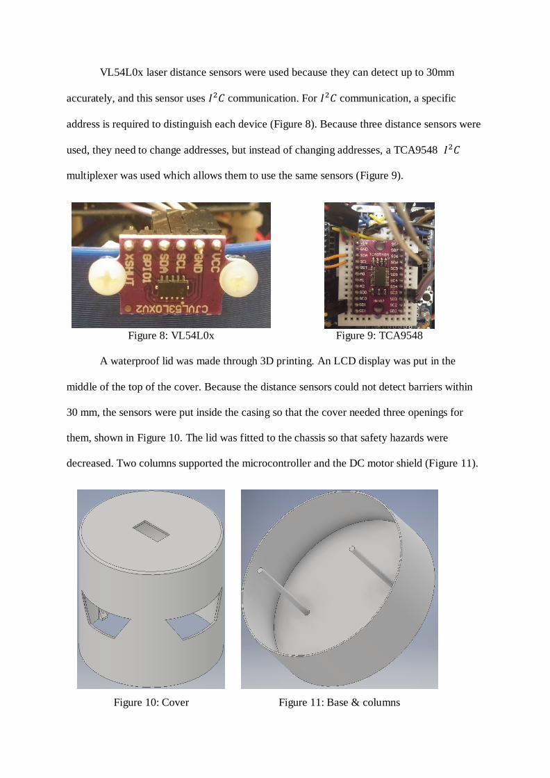
VL54L0x laser distance sensors were used because they can detect up to 30mm
accurately, and this sensor uses 𝐼2𝐶 communication. For 𝐼2𝐶 communication, a specific
address is required to distinguish each device (Figure 8). Because three distance sensors were
used, they need to change addresses, but instead of changing addresses, a TCA9548 𝐼2𝐶
multiplexer was used which allows them to use the same sensors (Figure 9).
Figure 8: VL54L0x Figure 9: TCA9548
A waterproof lid was made through 3D printing. An LCD display was put in the
middle of the top of the cover. Because the distance sensors could not detect barriers within
30 mm, the sensors were put inside the casing so that the cover needed three openings for
them, shown in Figure 10. The lid was fitted to the chassis so that safety hazards were
decreased. Two columns supported the microcontroller and the DC motor shield (Figure 11).
Figure 10: Cover Figure 11: Base & columns
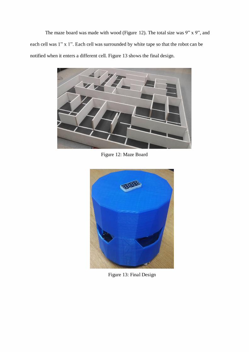
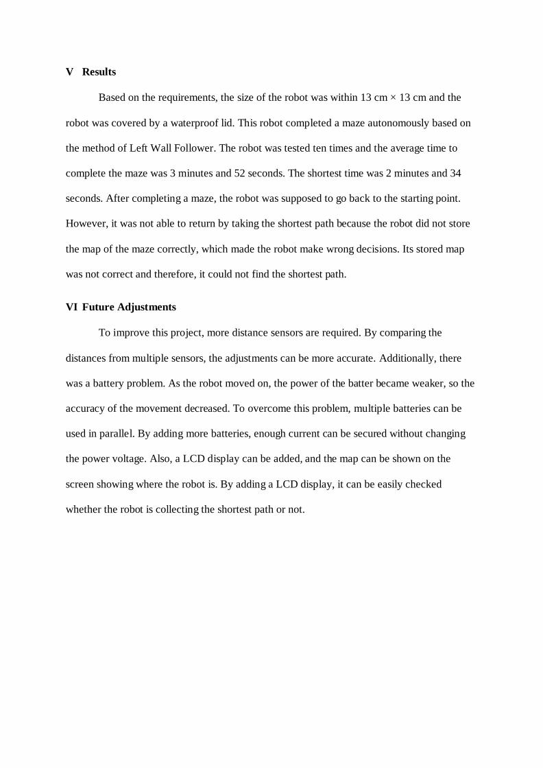
The maze board was made with wood (Figure 12). The total size was 9” x 9”, and
each cell was 1” x 1”. Each cell was surrounded by white tape so that the robot can be
notified when it enters a different cell. Figure 13 shows the final design.
Figure 12: Maze Board
Figure 13: Final Design

B. Schematic
Figure 14 shows the schematic of the maze robot. Each pin is named to indicate what
it is used for. All pins that have the same name are connected to each other.
Figure 14: Schematic
C. System Diagram
Figure 13 shows the entire system diagram. DC motor shield, 𝐼2𝐶 multiplexer, 4-digit
display, two encoders, and a line sensor were connected to the Arduino board. Except for the
power and ground pins, only 11 pins were required for the maze robot. Three distances
sensors were connected to the 𝐼2𝐶 multiplexer, and each sensor required 2 pins; SDA and
SCL.
Figure 15: System Diagram

D. Software
The robot movement was based on the direction of the wheels as outlined in Figure
14. When the robot moves back or forth, the two wheels had the same direction, and when the
robot turned right or left, the two wheels had different directions. Turning movement was
implemented by using both wheels so that the robot can turn without moving back or forth.
Figure 16: Movements
The maze robot was supposed to complete a maze, and then come back to the starting
point. To complete a maze, left wall follower method was chosen because it can complete
any maze. Left wall fallower consists of three decisions made by robot; has the robot reached
the end of the maze, is there a left wall, and is there a front wall? The algorithm is shown in
Figure 15. Based on the algorithm, the robot can complete any maze, but the problem was
efficiency. In the worst case, the robot had to search the whole maze to complete it. To
overcome this challenge, a maze map class was constructed. The class has x and y
coordinates, marked parameters, and some methods to change the parameters. While the
robot looked for the end of the maze, it marked each tile to indicate that the tile has been
traveled. Once the robot completes a maze, there are only three types of tiles; non-used tiles,

tiles used once, and tiles used at least twice. Tiles used once indicate the shortest path so on
the way back to the starting point, the robot goes through the tiles only used once.
Since the robot has no intuitive sense of direction, the robot needed a direction
parameter. Whenever the robot turned right or left, the direction parameter needed to change.
This functionality was added to improve navigation.
Figure 17: Left Wall follower Figure 18: Adjustment
The biggest challenge was making the robot move straight. The robot would not
remain at 90-degree angle to the wall and would often move toward or away from the wall so
that its path was not parallel. The robot programming was changed so that the robot
maintained a distance of 5 cm to the wall as it moved. Although the adjustments helped it
move straight, sometimes the robot ended up pointing the wrong direction. Therefore, another
adjustment was made. Based on its left or right sensor, the robot looked for the shortest
distance (Figure 16). Once the robot finds B in the diagram above, the robot points itself so
that its path is parallel to the wall. It can adjust the direction after each movement.
E. Sustainability
The robot was covered with a plastic box made by a 3D printer. It was designed to be
waterproof and to withstand a drop from 3 feet above the ground. A 9V DC battery was used
so that the robot can last a considerably long amount of time because the battery could be

replaced.
F. Environmental Impact
The maze board was made with wood. The robot did not make any polluting
substances. All these features lessened the impact on the environment. These environmental
factors follow IEEE Standard 1680-2009 [8].
G. Social Impact
This technology can be used in various robot types such as rescue robots, firefighting
robots, and delivery drones. Therefore, this robot can be beneficial to society.
H. Safety
Electrical motors require high voltage in general, but if the robot gets stuck, it will
require an even higher voltage to continue. The Arduino microcontroller is not able to handle
a higher voltage, so a DC motor shield was added to buffer the microcontroller against the
higher voltage that occurs in the motors. A waterproof round lid covered the robot so there
was no electric shock, fire, or energy-related hazards; this is compliant with IEC 60950-1
Standard of 2007 [9].
IV Project Cost
Table 1 shows the total cost
of this project. This project required
a microcontroller, a robot chassis,
sensors, etc. The total cost was
around $140, which is within the
sponsored budget, $400.
Table 1 – Cost list
Item Cost ($)
Arduino Uno R3 24.95
DC motor shield 9.9
2WD MiniQ Robot Chassis 34.35
MiniQ Robot Chassis Encoder 4.5
Distance sensors 44.85
Power supplies 8.41
Grayscale sensor 7.1
TCA9548A I2C Multiplexer 6.95
Breadboards 4.55
Total $ 140.15
V Results
Based on the requirements, the size of the robot was within 13 cm × 13 cm and the
robot was covered by a waterproof lid. This robot completed a maze autonomously based on
the method of Left Wall Follower. The robot was tested ten times and the average time to
complete the maze was 3 minutes and 52 seconds. The shortest time was 2 minutes and 34
seconds. After completing a maze, the robot was supposed to go back to the starting point.
However, it was not able to return by taking the shortest path because the robot did not store
the map of the maze correctly, which made the robot make wrong decisions. Its stored map
was not correct and therefore, it could not find the shortest path.
VI Future Adjustments
To improve this project, more distance sensors are required. By comparing the
distances from multiple sensors, the adjustments can be more accurate. Additionally, there
was a battery problem. As the robot moved on, the power of the batter became weaker, so the
accuracy of the movement decreased. To overcome this problem, multiple batteries can be
used in parallel. By adding more batteries, enough current can be secured without changing
the power voltage. Also, a LCD display can be added, and the map can be shown on the
screen showing where the robot is. By adding a LCD display, it can be easily checked
whether the robot is collecting the shortest path or not.
VII References
[1] “2WD miniQ Robot Chassis.” DFRobot. Web. 25 Apr. 2018.
https://www.dfrobot.com/product-367.html
[2] “MiniQ Robot chassis Encoder.” DFRobot. Web. 25 Apr. 2018.
https://www.dfrobot.com/product-823.html
[3] “How to Play With MiniQ 2WD Complete Robot Kit v2.0- Lesson 7 (Encoder).”
DFRobot. 24 Mar. 2017. Web. 25 Apr. 2018. https://www.dfrobot.com/blog-585.html
[4] “Gravity:Digital Line Tracking(Following) Sensor For Arduino.” DFRobot. Web. 25 Apr.
2018 https://www.dfrobot.com/product-85.html
[5] “Arduino Uno R3.” Pololu. Web. 26 Apr. 2018. https://www.pololu.com/product/2191
[6] “2x1A DC Motor Shield for Arduino.” Web. 26. Apr. 2018.
https://www.dfrobot.com/product-59.html
[7] “TM1637 LED DISPLAY MODULE 4 DIGIT 0.56 INCH.” OddWires. Web. 25 Apr.
2018. http://www.oddwires.com/tm1637-led-display-module-4-digit-0-56-inch/
[8] IEEE. “1680-2009-IEEE Standard for Environmental Assessment of Electronic Products”
IEEE Standards Association. Web. 3 Dec. 2017.
https://standards.ieee.org/findstds/standard/1680-2009.html
[9] IEC. “IEC 60950-1 Second edition 2005-12 Information Technology Equipment Safety”
IEC Standards Association. 2005. Web. 3 Dec. 2017
https://webstore.iec.ch/preview/info_iec60950-1%7Bed2.0%7Den_d.pdf
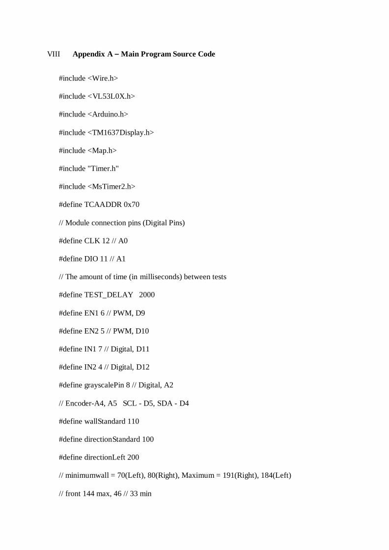
VIII Appendix A – Main Program Source Code
#include <Wire.h>
#include <VL53L0X.h>
#include <Arduino.h>
#include <TM1637Display.h>
#include <Map.h>
#include "Timer.h"
#include <MsTimer2.h>
#define TCAADDR 0x70
// Module connection pins (Digital Pins)
#define CLK 12 // A0
#define DIO 11 // A1
// The amount of time (in milliseconds) between tests
#define TEST_DELAY 2000
#define EN1 6 // PWM, D9
#define EN2 5 // PWM, D10
#define IN1 7 // Digital, D11
#define IN2 4 // Digital, D12
#define grayscalePin 8 // Digital, A2
// Encoder-A4, A5 SCL - D5, SDA - D4
#define wallStandard 110
#define directionStandard 100
#define directionLeft 200
// minimumwall = 70(Left), 80(Right), Maximum = 191(Right), 184(Left)
// front 144 max, 46 // 33 min
Map maze[9][9] = { {Map(0,8), Map(1,8), Map(2,8), Map(3,8), Map(4,8), Map(5,8),
Map(6,8), Map(7,8), Map(8,8)},
{Map(0,7), Map(1,7), Map(2,7), Map(3,7), Map(4,7), Map(5,7), Map(6,7),
Map(7,7), Map(8,7)},
{Map(0,6), Map(1,6), Map(2,6), Map(3,6), Map(4,6), Map(5,6), Map(6,6),
Map(7,6), Map(8,6)},
{Map(0,5), Map(1,5), Map(2,5), Map(3,5), Map(4,5), Map(5,5), Map(6,5),
Map(7,5), Map(8,5)},
{Map(0,4), Map(1,4), Map(2,4), Map(3,4), Map(4,4), Map(5,4), Map(6,4),
Map(7,4), Map(8,4)},
{Map(0,3), Map(1,3), Map(2,3), Map(3,3), Map(4,3), Map(5,3), Map(6,3),
Map(7,3), Map(8,3)},
{Map(0,2), Map(1,2), Map(2,3), Map(3,4), Map(4,5), Map(5,6), Map(6,7),
Map(7,8), Map(8,9)},
{Map(0,1), Map(1,1), Map(2,1), Map(3,1), Map(4,1), Map(5,1), Map(6,1),
Map(7,1), Map(8,1)},
{Map(0,0), Map(1,0), Map(2,0), Map(3,0), Map(4,0), Map(5,0), Map(6,0),
Map(7,0), Map(8,0)},
};
TM1637Display display(CLK, DIO);
VL53L0X sensorA;
VL53L0X sensorB;
VL53L0X sensorC;
//Timer t1;
bool linesensor();
int count1 = 0;
int count2 = 0;
int seconds = 0;
int minutes = 0;
int temp = 0;
void counta();
void countb();
bool lineSensor();
void movementTest();
void motor1(int pwm, boolean reverse);
void motor2(int pwm, boolean reverse);
void timer();
void turnRight(int distance);
void turnLeft(int distance);
void goForward(int distance);
void offsetLeft();
void lookForPath();
void offsetRight();
int sensor1(VL53L0X sensor);
int PWM_A = 70;
int PWM_B = 70;
int front = 0;
int left = 0;

int right = 0;
int preFront = 0;
int preLeft = 0;
int preRight = 0;
Map whereIam(0,0);
void adjustmentLeft(int num);
void adjustmentRight(int num);
int stuck = 0;
void sensor();
void offsetBack(int distance);
void countzero() {
count1 = 0;
count2 = 0;
}
void tcaselect(uint8_t i) {
if (i > 7) return;
Wire.beginTransmission(TCAADDR);
Wire.write(1 << i);
Wire.endTransmission();
}

void setup() {
whereIam = maze[0][0];
int i;
randomSeed(analogRead(0));
pinMode(grayscalePin,INPUT);
pinMode(2, INPUT_PULLUP);
pinMode(3, INPUT_PULLUP);
attachInterrupt(0, counta, CHANGE); // interrupt
attachInterrupt(1, countb, CHANGE); // interrupt
for (i = 4; i <= 7; i++) //For Arduino Motor Shield
pinMode(i, OUTPUT); //set pin 4,5,6,7 to output mode
display.setBrightness(0x0f);
MsTimer2::set(1000, timer); // 1 sec period
Serial.begin(9600);
Wire.begin();
tcaselect(4);
sensorA.init();
sensorA.setTimeout(500);
sensorA.startContinuous();
tcaselect(6);
sensorB.init();
sensorB.setTimeout(500);

sensorB.startContinuous();
tcaselect(1);
sensorC.init();
sensorC.setTimeout(500);
sensorC.startContinuous();
MsTimer2::start();
}
// center: left - 122, right - 123, front - 85
//
void adjustment();
void gotStuck();
void loop() {
long randNumber = 0;
int PWM_A = 80;
int PWM_B = 80;
int num = 9;
int line = 0;
int directionNumber;
while(true) {

sensor();
randNumber = random(300);
if(front > directionStandard) {
countzero();
goForward(13); //75 ~ 77 per one tile
countzero();
}
else if(right > directionLeft && left < directionLeft) {
countzero();
turnRight(20); // 24 is 90
countzero();
goForward(13);
countzero();
}
else if(left > directionLeft && right < directionLeft) {
countzero();
turnLeft(20);
countzero();
goForward(13);
countzero();
}
else if ( left < directionLeft && right < directionLeft) {
countzero();
turnLeft(49);
countzero();

goForward(13);
countzero();
}
else if ( left > directionLeft && right > directionLeft) {
if(randNumber % 2 == 0) {
countzero();
turnLeft(24);
countzero();
goForward(13);
countzero();
}
else {
countzero();
turnRight(24); // 24 is 90
countzero();
goForward(13);
countzero();
}
}
else {
countzero();
offsetBack(26);
countzero();
}
}

}
void gotStuck() {
countzero();
offsetBack(10);
countzero();
}
void lookForPath() {
while(front < 80) {
countzero();
offsetBack(3);
countzero();
sensor();
}
adjustmentRight(100);
}
void adjustmentRight(int num) {
int Max;
int i = 0;
Max = front;
for(i = 0; i < num; i++) {
countzero();

turnRight(2);
countzero();
sensor();
if(front > Max) {
Max = front;
}
else if (front < Max) {
turnLeft(2);
i++;
}
if( num > 7) {
break;
}
}
motor1(0, true);
motor2(0, true);
}
void adjustmentLeft(int num) {
int Max;
int i = 0;
Max = front;
for(i = 0; i < num; i++) {
countzero();
turnLeft(2);
countzero();
sensor();
if(front > Max) {
Max = front;
}
else if (front < Max) {
turnRight(2);
i++;
}
if( num > 10) {
break;
}
}
motor1(0, true);
motor2(0, true);
}
void sensor() {
tcaselect(4);
right = sensor1(sensorA);
tcaselect(6);
front = sensor1(sensorB);
tcaselect(1);
left = sensor1(sensorC);
}

void movementTest() {
countzero();
goForward(77); // per one tile 75 ~ 77;
countzero();
motor1(0, true);
motor2(0, true);
delay(3000);
countzero();
turnRight(24); // right 24 is 90 degree
countzero();
motor1(0, true);
motor2(0, true);
delay(3000);
countzero();
turnLeft(23); // left is 23 90 degree
countzero();
motor1(0, true);
motor2(0, true);
delay(3000);
}
void offsetBack(int distance) {
while((count1 + count2) < distance) {
motor1(50, true); // left

motor2(50, false); // right
}
motor1(0, true);
motor2(0, true);
}
void offsetForward() {
motor1(50, false); // left
motor2(50, true); // right
delay(50);
motor1(0, true);
motor2(0, true);
}
void offsetLeft() {
// Turn right
motor1(50, false);
motor2(50, false);
delay(10);
motor1(0, true);
motor2(0, true);
}
void offsetRight() {
// Turn left
motor1(50, true);
motor2(50, true);
delay(10);
motor1(0, true);
motor2(0, true);
}
void counta()
{
count1++;
}
void countb()
{
count2++;
}
void motor1(int pwm, boolean reverse) {
analogWrite(EN1, pwm); //set pwm control, 0 for stop, and 255 for maximum speed
if (reverse) {
digitalWrite(IN1, LOW);
}
else {
digitalWrite(IN1, HIGH);
}
}

void motor2(int pwm, boolean reverse) {
analogWrite(EN2, pwm);
if (reverse) {
digitalWrite(IN2, HIGH);
}
else {
digitalWrite(IN2, LOW);
}
}
void timer() {
int i;
int number;
int temp1, temp2;
seconds++;
if(seconds >= 60) {
minutes++;
seconds = 0;
}
if(minutes >= 60) {
minutes = 0;
seconds = 0;
}
number = minutes * 100 + seconds;

Serial.print("count1 is ");
Serial.println(count1);
Serial.print("count2 is ");
Serial.println(count2);
display.showNumberDecEx(number, (0x80 >> 1), true);
}
bool linesensor() {
if(digitalRead(grayscalePin))
{
// Serial.println("White detected");
return false;
}
else
{
// Serial.println("Black detected");
return true;
}
}
void turnRight(int distance) {
int j = 0;
int temp1, temp2;
int previousfront;
int k = 0;
while((count1 + count2) < distance) { // Turn left 23!!!
k++;
motor1(80, false);
motor2(80, false);
if (k % 3 == 0) {
sensor();
if(previousfront - front < 4 || front - previousfront < 4) {
j++;
}
previousfront = front;
if(j % 15 == 0) {
temp1 = count1;
temp2 = count2;
countzero();
offsetBack(26);
countzero();
count1 = temp1;
count2 = temp2;
}
}
}
motor1(0, true);
motor2(0, true);
}

void turnLeft(int distance) {
int j = 0;
int temp1, temp2;
int previousfront;
int k=0;
while((count1 + count2) < distance) { // Turn left 23!!!
k++;
motor1(80, true);
motor2(80, true);
if (k % 3 == 0) {
sensor();
if(previousfront - front < 4 || front - previousfront < 4) {
j++;
}
previousfront = front;
if(j % 15 == 0) {
temp1 = count1;
temp2 = count2;
countzero();
offsetBack(26);
countzero();
count1 = temp1;
count2 = temp2;
}
}

}
motor1(0, true);
motor2(0, true);
}
void goForward(int distance) {
int num1 = 0;
int temp1, temp2;
int k = 0;
int j = 0;
int previousfront = 0;
while((count1 + count2) < distance) {
sensor();
if(front < 60) {
temp1 = count1;
temp2 = count2;
countzero();
offsetBack(26);
countzero();
break;
}
k++;
motor1(PWM_A, false); // left
motor2(PWM_A, true); // right
//////////////// adjustments
if(num1 < 1) {
if(left < wallStandard && right < 200) {
temp1 = count1;
temp2 = count2;
countzero();
turnRight(2);
count1 = temp1;
count2 = temp2;
num1++;
}
else if (right < wallStandard && left < 200) {
temp1 = count1;
temp2 = count2;
countzero();
turnLeft(3);
countzero();
count1 = temp1;
count2 = temp2;
num1++;
}
else if (left > 130 && right > 200) {
temp1 = count1;
temp2 = count2;
countzero();

turnLeft(3);
countzero();
count1 = temp1;
count2 = temp2;
num1++;
}
else if (right > 130 && left > 200) {
temp1 = count1;
temp2 = count2;
countzero();
turnRight(2);
count1 = temp1;
count2 = temp2;
num1++;
}
}
if (k % 3 == 0) {
sensor();
if(previousfront - front < 4 || front - previousfront < 4) {
j++;
}
previousfront = front;
if(j % 15 == 0) {
temp1 = count1;

temp2 = count2;
countzero();
offsetBack(26);
countzero();
count1 = temp1;
count2 = temp2;
}
}
}
motor1(0, true);
motor2(0, true);
////////////////////////////////
}
int sensor1(VL53L0X sensor) {
int result = 0;
for(int i = 0; i < 2; i++) {
result += sensor.readRangeContinuousMillimeters();
delay(5);
}
return result/2;
}
IX Appendix B – Map Class Source Code
#ifndef __MAP__
#define __MAP__
class Map {
public:
Map(int input_x, int input_y);
void setXandY(int input_x, int input_y);
int getX();
int getY();
int getUsed();
void increaseUsed();
protected:
private:
int x;
int y;
int used_num;
};
#endif // __MAP__
extern "C" {
#include <stdlib.h>
#include <string.h>
}
#include <Map.h>
#include <Arduino.h>
Map::Map(int input_x, int input_y) {
x = input_x;
y = input_y;
used_num = 0; }
void Map::setXandY(int input_x, int input_y) {
x = input_x;
y = input_y; }
int Map::getX() {
return x; }
int Map::getY() {
return y; }

int Map::getUsed() {
return used_num; }
void Map::increaseUsed() {
used_num++; }