sm8taf2dpa management guide - transition … guide. management guide ... configuring dhcp snooping...
TRANSCRIPT
USER GUIDE
SM8TAF2DPAManagement Guide

MANAGEMENT GUIDE
SM8TAF2DPA ADVANCED SMART 10-PORT GE POE SWITCH
Layer 2 Advanced Smart Switchwith 8 10/100/1000BASE-T (RJ-45) PoE Ports,and 2 Gigabit SFP Ports
SM8TAF2DPA
E032012/ST-R01XXXXXXXXXXXXX
ABOUT THIS GUIDE
PURPOSE This guide gives specific information on how to operate and use the management functions of the switch.
AUDIENCE The guide is intended for use by network administrators who are responsible for operating and maintaining network equipment; consequently, it assumes a basic working knowledge of general switch functions, the Internet Protocol (IP), and Simple Network Management Protocol (SNMP).
CONVENTIONS The following conventions are used throughout this guide to show information:
NOTE: Emphasizes important information or calls your attention to related features or instructions.
CAUTION: Alerts you to a potential hazard that could cause loss of data, or damage the system or equipment.
WARNING: Alerts you to a potential hazard that could cause personal injury.
RELATED PUBLICATIONS The following publication details the hardware features of the switch, including the physical and performance-related characteristics, and how to install the switch:
The Installation Guide
Also, as part of the switch’s software, there is an online web-based help that describes all management related features.
REVISION HISTORY This section summarizes the changes in each revision of this guide.
APRIL 2012 REVISIONThis is the first version of this guide. This guide is valid for software release v1.0.0.5.
– 3 –

ABOUT THIS GUIDE
– 4 –
CONTENTS
ABOUT THIS GUIDE 3
CONTENTS 5
FIGURES 11
TABLES 15
SECTION I GETTING STARTED 17
1 INTRODUCTION 19
Key Features 19
Description of Software Features 20
System Defaults 24
2 INITIAL SWITCH CONFIGURATION 27
SECTION II WEB CONFIGURATION 29
3 USING THE WEB INTERFACE 31
Navigating the Web Browser Interface 31
Home Page 31
Configuration Options 32
Panel Display 32
Main Menu 33
4 CONFIGURING THE SWITCH 41
Configuring System Information 41
Setting an IP Address 42
Setting an IPv4 Address 42
Setting an IPv6 Address 44
Configuring NTP Service 46
Configuring Remote Log Messages 47
Configuring Power Reduction 48
Controlling LED Intensity 48
– 5 –

CONTENTS
Reducing Power to Idle Queue Circuits 50
Configuring Thermal Protection 51
Configuring Port Connections 52
Configuring Security 55
Configuring User Accounts 55
Configuring User Privilege Levels 57
Configuring The Authentication Method For Management Access 58
Configuring SSH 61
Configuring HTTPS 62
Filtering IP Addresses for Management Access 63
Using Simple Network Management Protocol 64
Configuring Port Limit Controls 75
Configuring Authentication Through Network Access Servers 77
Filtering Traffic with Access Control Lists 88
Configuring DHCP Snooping 98
Configuring DHCP Relay and Option 82 Information 101
Configuring IP Source Guard 102
Configuring ARP Inspection 106
Specifying Authentication Servers 109
Creating Trunk Groups 111
Configuring Static Trunks 112
Configuring LACP 114
Configuring the Spanning Tree Algorithm 116
Configuring Global Settings for STA 118
Configuring Multiple Spanning Trees 122
Configuring Spanning Tree Bridge Priorities 124
Configuring STP/RSTP/CIST Interfaces 125
Configuring MIST Interfaces 128
Multicast VLAN Registration 130
IGMP Snooping 133
Configuring Global and Port-Related Settings for IGMP Snooping 133
Configuring VLAN Settings for IGMP Snooping and Query 136
Configuring IGMP Filtering 138
MLD Snooping 139
Configuring Global and Port-Related Settings for MLD Snooping 139
Configuring VLAN Settings for MLD Snooping and Query 142
– 6 –
CONTENTS
Configuring MLD Filtering 144
Link Layer Discovery Protocol 145
Configuring LLDP Timing and TLVs 145
Configuring LLDP-MED TLVs 148
Power over Ethernet 154
Configuring the MAC Address Table 157
IEEE 802.1Q VLANs 159
Assigning Ports to VLANs 160
Configuring VLAN Attributes for Port Members 161
Configuring Private VLANs 164
Using Port Isolation 165
Configuring MAC-based VLANs 166
Protocol VLANs 167
Configuring Protocol VLAN Groups 168
Mapping Protocol Groups to Ports 169
Managing VoIP Traffic 170
Configuring VoIP Traffic 171
Configuring Telephony OUI 173
Quality of Service 174
Configuring Port Classification 175
Configuring Egress Port Scheduler 177
Configuring Egress Port Shaper 180
Configuring Port Remarking Mode 180
Configuring Port DSCP Translation and Rewriting 183
Configuring DSCP-based QoS Ingress Classification 185
Configuring DSCP Translation 186
Configuring DSCP Classification 187
Configuring QoS Control Lists 188
Configuring Storm Control 192
Configuring Port Mirroring 193
Configuring UPnP 195
5 MONITORING THE SWITCH 197
Displaying Basic Information About the System 197
Displaying System Information 197
Displaying CPU Utilization 198
Displaying Log Messages 199
– 7 –
CONTENTS
Displaying Log Details 200
Displaying Thermal Protection 201
Displaying Information About Ports 202
Displaying Port Status On the Front Panel 202
Displaying an Overview of Port Statistics 202
Displaying QoS Statistics 203
Displaying QCL Status 204
Displaying Detailed Port Statistics 205
Displaying Information About Security Settings 208
Displaying Access Management Statistics 208
Displaying Information About Switch Settings for Port Security 209
Displaying Information About Learned MAC Addresses 211
Displaying Port Status for Authentication Services 212
Displaying Port Statistics for 802.1X or Remote Authentication Service 213
Displaying ACL Status 217
Displaying Statistics for DHCP Snooping 219
Displaying DHCP Relay Statistics 220
Displaying MAC Address Bindings for ARP Packets 221
Displaying Entries in the IP Source Guard Table 222
Displaying Information on Authentication Servers 223
Displaying a List of Authentication Servers 223
Displaying Statistics for Configured Authentication Servers 224
Displaying Information on LACP 227
Displaying an Overview of LACP Groups 227
Displaying LACP Port Status 228
Displaying LACP Port Statistics 229
Displaying Information on the Spanning Tree 230
Displaying Bridge Status for STA 230
Displaying Port Status for STA 232
Displaying Port Statistics for STA 233
Displaying MVR Information 234
Displaying MVR Statistics 234
Displaying MVR Group Information 235
Showing IGMP Snooping Information 236
Showing IGMP Snooping Status 236
Showing IGMP Snooping Group Information 237
– 8 –
CONTENTS
Showing IPv4 SSM Information 238
Showing MLD Snooping Information 239
Showing MLD Snooping Status 239
Showing MLD Snooping Group Information 240
Showing IPv6 SSM Information 241
Displaying LLDP Information 242
Displaying LLDP Neighbor Information 242
Displaying LLDP-MED Neighbor Information 243
Displaying LLDP Neighbor PoE Information 245
Displaying LLDP Neighbor EEE Information 246
Displaying LLDP Port Statistics 247
Displaying PoE Status 249
Displaying the MAC Address Table 250
Displaying Information About VLANs 251
VLAN Membership 251
VLAN Port Status 252
Displaying Information About MAC-based VLANs 253
6 PERFORMING BASIC DIAGNOSTICS 255
Pinging an IPv4 or IPv6 Address 255
Running Cable Diagnostics 256
7 PERFORMING SYSTEM MAINTENANCE 259
Restarting the Switch 259
Restoring Factory Defaults 260
Upgrading Firmware 260
Managing Configuration Files 261
Saving Configuration Settings 261
Restoring Configuration Settings 262
SECTION III APPENDICES 263
A SOFTWARE SPECIFICATIONS 265
Software Features 265
Management Features 266
Standards 267
Management Information Bases 267
– 9 –
CONTENTS
B TROUBLESHOOTING 269
Problems Accessing the Management Interface 269
Using System Logs 270
C LICENSE INFORMATION 271
The GNU General Public License 271
GLOSSARY 275
INDEX 283
– 10 –
FIGURES
Figure 1: Home Page 31
Figure 2: Front Panel Indicators 32
Figure 3: System Information Configuration 42
Figure 4: IP Configuration 44
Figure 5: IPv6 Configuration 46
Figure 6: NTP Configuration 47
Figure 7: Configuring Settings for Remote Logging of Error Messages 48
Figure 8: Configuring LED Power Reduction 49
Figure 9: Configuring EEE Power Reduction 51
Figure 10: Configuring Thermal Protection 52
Figure 11: Port Configuration 54
Figure 12: Showing User Accounts 56
Figure 13: Configuring User Accounts 57
Figure 14: Configuring Privilege Levels 58
Figure 15: Authentication Server Operation 59
Figure 16: Authentication Method for Management Access 60
Figure 17: SSH Configuration 61
Figure 18: HTTPS Configuration 63
Figure 19: Access Management Configuration 64
Figure 20: SNMP System Configuration 69
Figure 21: SNMPv3 Community Configuration 70
Figure 22: SNMPv3 User Configuration 71
Figure 23: SNMPv3 Group Configuration 73
Figure 24: SNMPv3 View Configuration 74
Figure 25: SNMPv3 Access Configuration 75
Figure 26: Port Limit Control Configuration 77
Figure 27: Using Port Security 78
Figure 28: Network Access Server Configuration 88
Figure 29: ACL Port Configuration 90
Figure 30: ACL Rate Limiter Configuration 91
Figure 31: Access Control List Configuration 98
– 11 –
FIGURES
Figure 32: DHCP Snooping Configuration 101
Figure 33: DHCP Relay Configuration 102
Figure 34: Configuring Global and Port-based Settings for IP Source Guard 104
Figure 35: Configuring Static Bindings for IP Source Guard 106
Figure 36: Configuring Global and Port Settings for ARP Inspection 108
Figure 37: Configuring Static Bindings for ARP Inspection 109
Figure 38: Authentication Configuration 110
Figure 39: Static Trunk Configuration 114
Figure 40: LACP Port Configuration 116
Figure 41: STP Root Ports and Designated Ports 117
Figure 42: MSTP Region, Internal Spanning Tree, Multiple Spanning Tree 117
Figure 43: Common Internal Spanning Tree, Common Spanning Tree, Internal Spanning Tree118
Figure 44: STA Bridge Configuration 121
Figure 45: Adding a VLAN to an MST Instance 123
Figure 46: Configuring STA Bridge Priorities 124
Figure 47: STP/RSTP/CIST Port Configuration 128
Figure 48: MSTI Port Configuration 129
Figure 49: MVR Concept 130
Figure 50: Configuring MVR 132
Figure 51: Configuring Global and Port-related Settings for IGMP Snooping 136
Figure 52: Configuring VLAN Settings for IGMP Snooping and Query 138
Figure 53: IGMP Snooping Port Group Filtering Configuration 139
Figure 54: Configuring Global and Port-related Settings for MLD Snooping 142
Figure 55: Configuring VLAN Settings for MLD Snooping and Query 144
Figure 56: MLD Snooping Port Group Filtering Configuration 145
Figure 57: LLDP Configuration 148
Figure 58: LLDP-MED Configuration 154
Figure 59: Configuring PoE Settings 157
Figure 60: MAC Address Table Configuration 159
Figure 61: VLAN Membership Configuration 161
Figure 62: VLAN Port Configuration 163
Figure 63: Private VLAN Membership Configuration 165
Figure 64: Port Isolation Configuration 165
Figure 65: Configuring MAC-Based VLANs 167
Figure 66: Configuring Protocol VLANs 169
Figure 67: Assigning Ports to Protocol VLANs 170
– 12 –
FIGURES
Figure 68: Configuring Global and Port Settings for a Voice VLAN 173
Figure 69: Configuring an OUI Telephony List 174
Figure 70: Configuring Ingress Port QoS Classification 176
Figure 71: Configuring Ingress Port Tag Classification 177
Figure 72: Displaying Egress Port Schedulers 179
Figure 73: Configuring Egress Port Schedulers and Shapers 179
Figure 74: Displaying Egress Port Shapers 180
Figure 75: Displaying Port Tag Remarking Mode 182
Figure 76: Configuring Port Tag Remarking Mode 183
Figure 77: Configuring Port DSCP Translation and Rewriting 185
Figure 78: Configuring DSCP-based QoS Ingress Classification 186
Figure 79: Configuring DSCP Translation and Re-mapping 187
Figure 80: Mapping DSCP to CoS/DPL Values 188
Figure 81: QoS Control List Configuration 192
Figure 82: Storm Control Configuration 193
Figure 83: Mirror Configuration 194
Figure 84: UPnP Configuration 196
Figure 85: System Information 198
Figure 86: CPU Load 199
Figure 87: System Log Information 200
Figure 88: Detailed System Log Information 200
Figure 89: Thermal Protection Status 201
Figure 90: Port State Overview 202
Figure 91: Port Statistics Overview 203
Figure 92: Queueing Counters 203
Figure 93: QoS Control List Status 205
Figure 94: Detailed Port Statistics 207
Figure 95: Access Management Statistics 208
Figure 96: Port Security Switch Status 210
Figure 97: Port Security Port Status 211
Figure 98: Network Access Server Switch Status 213
Figure 99: NAS Statistics for Specified Port 217
Figure 100: ACL Status 218
Figure 101: DHCP Snooping Statistics 220
Figure 102: DHCP Relay Statistics 221
Figure 103: Dynamic ARP Inspection Table 222
– 13 –
FIGURES
Figure 104: Dynamic IP Source Guard Table 222
Figure 105: RADIUS Overview 223
Figure 106: RADIUS Details 227
Figure 107: LACP System Status 228
Figure 108: LACP Port Status 229
Figure 109: LACP Port Statistics 229
Figure 110: Spanning Tree Bridge Status 232
Figure 111: Spanning Tree Detailed Bridge Status 232
Figure 112: Spanning Tree Port Status 233
Figure 113: Spanning Tree Port Statistics 234
Figure 114: MVR Statistics 235
Figure 115: MVR Group Information 236
Figure 116: IGMP Snooping Status 237
Figure 117: IGMP Snooping Group Information 238
Figure 118: IPv4 SSM Information 239
Figure 119: MLD Snooping Status 240
Figure 120: MLD Snooping Group Information 241
Figure 121: IPv6 SSM Information 241
Figure 122: LLDP Neighbor Information 243
Figure 123: LLDP-MED Neighbor Information 245
Figure 124: LLDP Neighbor PoE Information 246
Figure 125: LLDP Neighbor EEE Information 247
Figure 126: LLDP Port Statistics 249
Figure 127: Power over Ethernet Status 250
Figure 128: MAC Address Table 251
Figure 129: Showing VLAN Members 252
Figure 130: Showing VLAN Port Status 253
Figure 131: Showing MAC-based VLAN Configuration 254
Figure 132: ICMP Ping 256
Figure 133: VeriPHY Cable Diagnostics 257
Figure 134: Restart Device 259
Figure 135: Factory Defaults 260
Figure 136: Software Upload 261
Figure 137: Configuration Download 261
Figure 138: Configuration Upload 262
– 14 –
TABLES
Table 1: Key Features 19
Table 2: System Defaults 24
Table 3: Web Page Configuration Buttons 32
Table 4: Main Menu 33
Table 5: HTTPS System Support 62
Table 6: SNMP Security Models and Levels 65
Table 7: Dynamic QoS Profiles 81
Table 8: QCE Modification Buttons 92
Table 9: Recommended STA Path Cost Range 125
Table 10: Recommended STA Path Costs 126
Table 11: Default STA Path Costs 126
Table 12: QCE Modification Buttons 189
Table 13: System Capabilities 242
Table 14: Troubleshooting Chart 269
– 15 –

TABLES
– 16 –

SECTION I
GETTING STARTED
This section provides an overview of the switch, and introduces some basic concepts about network switches. It also describes the basic settings required to access the management interface.
This section includes these chapters:
◆ "Introduction" on page 19
◆ "Initial Switch Configuration" on page 27
– 17 –

SECTION I | Getting Started
– 18 –
1 INTRODUCTION
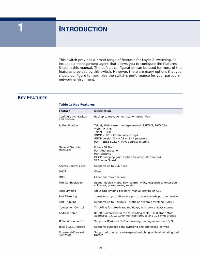
This switch provides a broad range of features for Layer 2 switching. It includes a management agent that allows you to configure the features listed in this manual. The default configuration can be used for most of the features provided by this switch. However, there are many options that you should configure to maximize the switch’s performance for your particular network environment.
KEY FEATURES
Table 1: Key Features
Feature Description
Configuration Backup and Restore
Backup to management station using Web
Authentication Telnet, Web – user name/password, RADIUS, TACACS+Web – HTTPSTelnet – SSHSNMP v1/2c - Community stringsSNMP version 3 – MD5 or SHA passwordPort – IEEE 802.1X, MAC address filtering
General Security Measures
Private VLANsPort AuthenticationPort SecurityDHCP Snooping (with Option 82 relay information)IP Source Guard
Access Control Lists Supports up to 256 rules
DHCP Client
DNS Client and Proxy service
Port Configuration Speed, duplex mode, flow control, MTU, response to excessive collisions, power saving mode
Rate Limiting Input rate limiting per port (manual setting or ACL)
Port Mirroring 1 sessions, up to 10 source port to one analysis port per session
Port Trunking Supports up to 5 trunks – static or dynamic trunking (LACP)
Congestion Control Throttling for broadcast, multicast, unknown unicast storms
Address Table 8K MAC addresses in the forwarding table, 1000 static MAC addresses, 1K L2 IGMP multicast groups and 128 MVR groups
IP Version 4 and 6 Supports IPv4 and IPv6 addressing, management, and QoS
IEEE 802.1D Bridge Supports dynamic data switching and addresses learning
Store-and-Forward Switching
Supported to ensure wire-speed switching while eliminating bad frames
– 19 –
CHAPTER 1 | IntroductionDescription of Software Features
DESCRIPTION OF SOFTWARE FEATURES
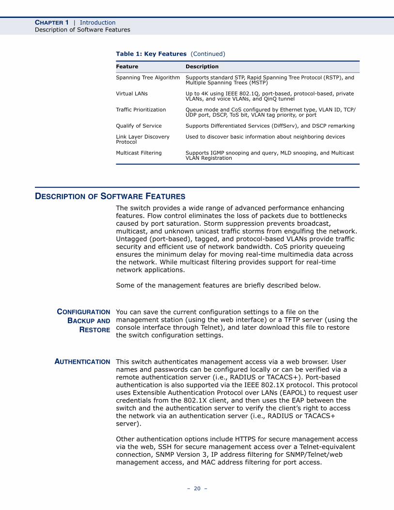
The switch provides a wide range of advanced performance enhancing features. Flow control eliminates the loss of packets due to bottlenecks caused by port saturation. Storm suppression prevents broadcast, multicast, and unknown unicast traffic storms from engulfing the network. Untagged (port-based), tagged, and protocol-based VLANs provide traffic security and efficient use of network bandwidth. CoS priority queueing ensures the minimum delay for moving real-time multimedia data across the network. While multicast filtering provides support for real-time network applications.
Some of the management features are briefly described below.
CONFIGURATIONBACKUP AND
RESTORE
You can save the current configuration settings to a file on the management station (using the web interface) or a TFTP server (using the console interface through Telnet), and later download this file to restore the switch configuration settings.
AUTHENTICATION This switch authenticates management access via a web browser. User names and passwords can be configured locally or can be verified via a remote authentication server (i.e., RADIUS or TACACS+). Port-based authentication is also supported via the IEEE 802.1X protocol. This protocol uses Extensible Authentication Protocol over LANs (EAPOL) to request user credentials from the 802.1X client, and then uses the EAP between the switch and the authentication server to verify the client’s right to access the network via an authentication server (i.e., RADIUS or TACACS+ server).
Other authentication options include HTTPS for secure management access via the web, SSH for secure management access over a Telnet-equivalent connection, SNMP Version 3, IP address filtering for SNMP/Telnet/web management access, and MAC address filtering for port access.
Spanning Tree Algorithm Supports standard STP, Rapid Spanning Tree Protocol (RSTP), and Multiple Spanning Trees (MSTP)
Virtual LANs Up to 4K using IEEE 802.1Q, port-based, protocol-based, private VLANs, and voice VLANs, and QinQ tunnel
Traffic Prioritization Queue mode and CoS configured by Ethernet type, VLAN ID, TCP/UDP port, DSCP, ToS bit, VLAN tag priority, or port
Qualify of Service Supports Differentiated Services (DiffServ), and DSCP remarking
Link Layer Discovery Protocol
Used to discover basic information about neighboring devices
Multicast Filtering Supports IGMP snooping and query, MLD snooping, and Multicast VLAN Registration
Table 1: Key Features (Continued)
Feature Description
– 20 –
CHAPTER 1 | IntroductionDescription of Software Features
ACCESS CONTROLLISTS
ACLs provide packet filtering for IP frames (based on protocol, TCP/UDP port number or frame type) or layer 2 frames (based on any destination MAC address for unicast, broadcast or multicast, or based on VLAN ID or VLAN tag priority). ACLs can by used to improve performance by blocking unnecessary network traffic or to implement security controls by restricting access to specific network resources or protocols. Policies can be used to differentiate service for client ports, server ports, network ports or guest ports. They can also be used to strictly control network traffic by only allowing incoming frames that match the source MAC and source IP on specific port.
PORT CONFIGURATION You can manually configure the speed and duplex mode, and flow control used on specific ports, or use auto-negotiation to detect the connection settings used by the attached device. Use the full-duplex mode on ports whenever possible to double the throughput of switch connections. Flow control should also be enabled to control network traffic during periods of congestion and prevent the loss of packets when port buffer thresholds are exceeded. The switch supports flow control based on the IEEE 802.3x standard (now incorporated in IEEE 802.3-2002).
RATE LIMITING This feature controls the maximum rate for traffic transmitted or received on an interface. Rate limiting is configured on interfaces at the edge of a network to limit traffic into or out of the network. Traffic that falls within the rate limit is transmitted, while packets that exceed the acceptable amount of traffic are dropped.
PORT MIRRORING The switch can unobtrusively mirror traffic from any port to a monitor port. You can then attach a protocol analyzer or RMON probe to this port to perform traffic analysis and verify connection integrity.
PORT TRUNKING Ports can be combined into an aggregate connection. Trunks can be manually set up or dynamically configured using Link Aggregation Control Protocol (LACP – IEEE 802.3-2005). The additional ports dramatically increase the throughput across any connection, and provide redundancy by taking over the load if a port in the trunk should fail. The switch supports up to 5 trunks.
STORM CONTROL Broadcast, multicast and unknown unicast storm suppression prevents traffic from overwhelming the network.When enabled on a port, the level of broadcast traffic passing through the port is restricted. If broadcast traffic rises above a pre-defined threshold, it will be throttled until the level falls back beneath the threshold.
STATIC ADDRESSES A static address can be assigned to a specific interface on this switch. Static addresses are bound to the assigned interface and will not be moved. When a static address is seen on another interface, the address will
– 21 –
CHAPTER 1 | IntroductionDescription of Software Features
be ignored and will not be written to the address table. Static addresses can be used to provide network security by restricting access for a known host to a specific port.
IEEE 802.1D BRIDGE The switch supports IEEE 802.1D transparent bridging. The address table facilitates data switching by learning addresses, and then filtering or forwarding traffic based on this information. The address table supports up to 16K addresses.
STORE-AND-FORWARDSWITCHING
The switch copies each frame into its memory before forwarding them to another port. This ensures that all frames are a standard Ethernet size and have been verified for accuracy with the cyclic redundancy check (CRC). This prevents bad frames from entering the network and wasting bandwidth.
To avoid dropping frames on congested ports, the switch provides 8 MB for frame buffering. This buffer can queue packets awaiting transmission on congested networks.
SPANNING TREEALGORITHM
The switch supports these spanning tree protocols:
◆ Spanning Tree Protocol (STP, IEEE 802.1D) – Supported by using the STP backward compatible mode provided by RSTP. STP provides loop detection. When there are multiple physical paths between segments, this protocol will choose a single path and disable all others to ensure that only one route exists between any two stations on the network. This prevents the creation of network loops. However, if the chosen path should fail for any reason, an alternate path will be activated to maintain the connection.
◆ Rapid Spanning Tree Protocol (RSTP, IEEE 802.1w) – This protocol reduces the convergence time for network topology changes to about 3 to 5 seconds, compared to 30 seconds or more for the older IEEE 802.1D STP standard. It is intended as a complete replacement for STP, but can still interoperate with switches running the older standard by automatically reconfiguring ports to STP-compliant mode if they detect STP protocol messages from attached devices.
◆ Multiple Spanning Tree Protocol (MSTP, IEEE 802.1s) – This protocol is a direct extension of RSTP. It can provide an independent spanning tree for different VLANs. It simplifies network management, provides for even faster convergence than RSTP by limiting the size of each region, and prevents VLAN members from being segmented from the rest of the group (as sometimes occurs with IEEE 802.1D STP).
– 22 –
CHAPTER 1 | IntroductionDescription of Software Features
VIRTUAL LANS The switch supports up to 4096 VLANs. A Virtual LAN is a collection of network nodes that share the same collision domain regardless of their physical location or connection point in the network. The switch supports tagged VLANs based on the IEEE 802.1Q standard. Members of VLAN groups can be manually assigned to a specific set of VLANs. This allows the switch to restrict traffic to the VLAN groups to which a user has been assigned. By segmenting your network into VLANs, you can:
◆ Eliminate broadcast storms which severely degrade performance in a flat network.
◆ Simplify network management for node changes/moves by remotely configuring VLAN membership for any port, rather than having to manually change the network connection.
◆ Provide data security by restricting all traffic to the originating VLAN.
◆ Use private VLANs to restrict traffic to pass only between data ports and the uplink ports, thereby isolating adjacent ports within the same VLAN, and allowing you to limit the total number of VLANs that need to be configured.
◆ Use protocol VLANs to restrict traffic to specified interfaces based on protocol type.
IEEE 802.1QTUNNELING (QINQ)
This feature is designed for service providers carrying traffic for multiple customers across their networks. QinQ tunneling is used to maintain customer-specific VLAN and Layer 2 protocol configurations even when different customers use the same internal VLAN IDs. This is accomplished by inserting Service Provider VLAN (SPVLAN) tags into the customer’s frames when they enter the service provider’s network, and then stripping the tags when the frames leave the network.
TRAFFICPRIORITIZATION
This switch prioritizes each packet based on the required level of service, using four priority queues with strict or Weighted Round Robin queuing. It uses IEEE 802.1p and 802.1Q tags to prioritize incoming traffic based on input from the end-station application. These functions can be used to provide independent priorities for delay-sensitive data and best-effort data.
This switch also supports several common methods of prioritizing layer 3/4 traffic to meet application requirements. Traffic can be prioritized based on the priority bits in the IP frame’s Type of Service (ToS) octet or the number of the TCP/UDP port. When these services are enabled, the priorities are mapped to a Class of Service value by the switch, and the traffic then sent to the corresponding output queue.
– 23 –
CHAPTER 1 | IntroductionSystem Defaults
QUALITY OF SERVICE Differentiated Services (DiffServ) provides policy-based management mechanisms used for prioritizing network resources to meet the requirements of specific traffic types on a per-hop basis. Each packet is classified upon entry into the network based on access lists, DSCP values, or VLAN lists. Using access lists allows you select traffic based on Layer 2, Layer 3, or Layer 4 information contained in each packet. Based on network policies, different kinds of traffic can be marked for different kinds of forwarding.
MULTICAST FILTERING Specific multicast traffic can be assigned to its own VLAN to ensure that it does not interfere with normal network traffic and to guarantee real-time delivery by setting the required priority level for the designated VLAN. The switch uses IGMP Snooping and Query to manage multicast group registration for IPv4 traffic, and MLD Snooping for IPv6 traffic. It also supports Multicast VLAN Registration (MVR) which allows common multicast traffic, such as television channels, to be transmitted across a single network-wide multicast VLAN shared by hosts residing in other standard or private VLAN groups, while preserving security and data isolation for normal traffic.
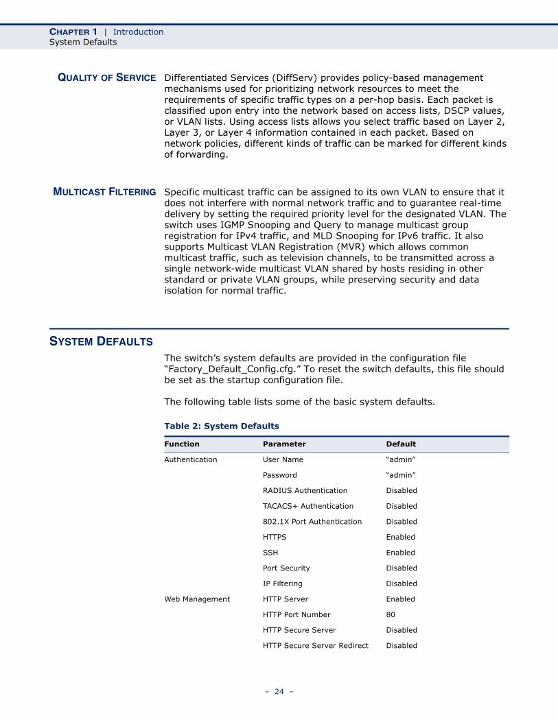
SYSTEM DEFAULTS
The switch’s system defaults are provided in the configuration file “Factory_Default_Config.cfg.” To reset the switch defaults, this file should be set as the startup configuration file.
The following table lists some of the basic system defaults.
Table 2: System Defaults
Function Parameter Default
Authentication User Name “admin”
Password “admin”
RADIUS Authentication Disabled
TACACS+ Authentication Disabled
802.1X Port Authentication Disabled
HTTPS Enabled
SSH Enabled
Port Security Disabled
IP Filtering Disabled
Web Management HTTP Server Enabled
HTTP Port Number 80
HTTP Secure Server Disabled
HTTP Secure Server Redirect Disabled
– 24 –
CHAPTER 1 | IntroductionSystem Defaults
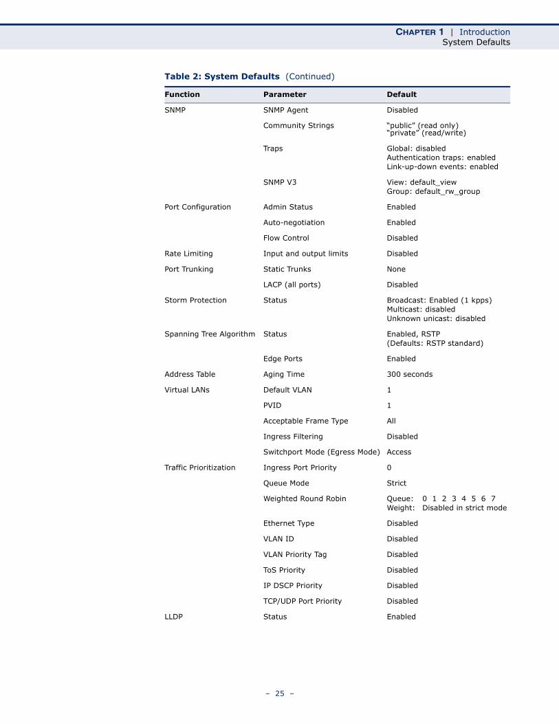
SNMP SNMP Agent Disabled
Community Strings “public” (read only) “private” (read/write)
Traps Global: disabledAuthentication traps: enabledLink-up-down events: enabled
SNMP V3 View: default_viewGroup: default_rw_group
Port Configuration Admin Status Enabled
Auto-negotiation Enabled
Flow Control Disabled
Rate Limiting Input and output limits Disabled
Port Trunking Static Trunks None
LACP (all ports) Disabled
Storm Protection Status Broadcast: Enabled (1 kpps)Multicast: disabledUnknown unicast: disabled
Spanning Tree Algorithm Status Enabled, RSTP(Defaults: RSTP standard)
Edge Ports Enabled
Address Table Aging Time 300 seconds
Virtual LANs Default VLAN 1
PVID 1
Acceptable Frame Type All
Ingress Filtering Disabled
Switchport Mode (Egress Mode) Access
Traffic Prioritization Ingress Port Priority 0
Queue Mode Strict
Weighted Round Robin Queue: 0 1 2 3 4 5 6 7Weight: Disabled in strict mode
Ethernet Type Disabled
VLAN ID Disabled
VLAN Priority Tag Disabled
ToS Priority Disabled
IP DSCP Priority Disabled
TCP/UDP Port Priority Disabled
LLDP Status Enabled
Table 2: System Defaults (Continued)
Function Parameter Default
– 25 –
CHAPTER 1 | IntroductionSystem Defaults
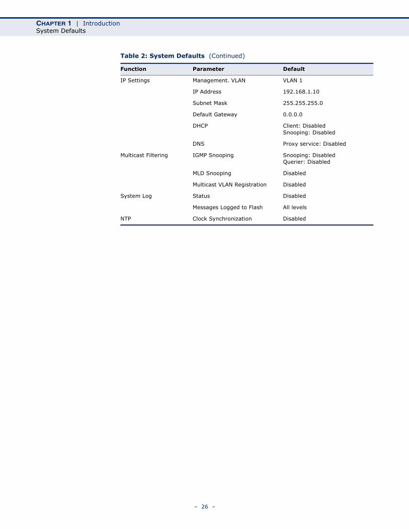
IP Settings Management. VLAN VLAN 1
IP Address 192.168.1.10
Subnet Mask 255.255.255.0
Default Gateway 0.0.0.0
DHCP Client: DisabledSnooping: Disabled
DNS Proxy service: Disabled
Multicast Filtering IGMP Snooping Snooping: DisabledQuerier: Disabled
MLD Snooping Disabled
Multicast VLAN Registration Disabled
System Log Status Disabled
Messages Logged to Flash All levels
NTP Clock Synchronization Disabled
Table 2: System Defaults (Continued)
Function Parameter Default
– 26 –
2 INITIAL SWITCH CONFIGURATION
This chapter includes information on connecting to the switch and basic configuration procedures.
To make use of the management features of your switch, you must first configure it with an IP address that is compatible with the network in which it is being installed. This should be done before you permanently install the switch in the network.
Follow this procedure:
1. Place the switch close to the PC that you intend to use for configuration. It helps if you can see the front panel of the switch while working on your PC.
2. Connect the Ethernet port of your PC to any port on the front panel of the switch. Connect power to the switch and verify that you have a link by checking the front-panel LEDs.
3. Check that your PC has an IP address on the same subnet as the switch. The default IP address of the switch is 192.168.1.10 and the subnet mask is 255.255.255.0, so the PC and switch are on the same subnet if they both have addresses that start 192.168.1.x. If the PC and switch are not on the same subnet, you must manually set the PC’s IP address to 192.168.1.x (where “x” is any number from 1 to 254, except 10).
4. Open your web browser and enter the address http://192.168.1.10. If your PC is properly configured, you will see the login page of the switch. If you do not see the login page, repeat step 3.
5. Enter “admin” for the user name and password, and then click on the Login button.
6. From the menu, click System, and then IP. To request an address from a local DHCP Server, mark the DHCP Client check box. To configure a static address, enter the new IP Address, IP Mask, and other optional parameters for the switch, and then click on the Save button.
If you need to configure an IPv6 address, select IPv6 from the System menu, and either submit a request for an address from a local DHCPv6 server by marking the Auto Configuration check box, or configure a static address by filling in the parameters for an address, network prefix length, and gateway router.
No other configuration changes are required at this stage, but it is recommended that you change the administrator’s password before
– 27 –

CHAPTER 2 | Initial Switch Configuration
logging out. To change the password, click Security and then Users. Select “admin” from the User Configuration list, fill in the Password fields, and then click Save.
– 28 –
SECTION II
WEB CONFIGURATION
This section describes the basic switch features, along with a detailed description of how to configure each feature via a web browser.
This section includes these chapters:
◆ "Using the Web Interface" on page 31
◆ "Configuring the Switch" on page 41
◆ "Monitoring the Switch" on page 197
◆ "Performing Basic Diagnostics" on page 255
◆ "Performing System Maintenance" on page 259
– 29 –

SECTION II | Web Configuration
– 30 –
3 USING THE WEB INTERFACE
This switch provides an embedded HTTP web agent. Using a web browser you can configure the switch and view statistics to monitor network activity. The web agent can be accessed by any computer on the network using a standard web browser (Internet Explorer 5.0, Netscape 6.2, Mozilla Firefox 2.0.0.0, or more recent versions).
NAVIGATING THE WEB BROWSER INTERFACE
To access the web-browser interface you must first enter a user name and password. The administrator has Read/Write access to all configuration parameters and statistics. The default user name and password for the administrator is “admin.”
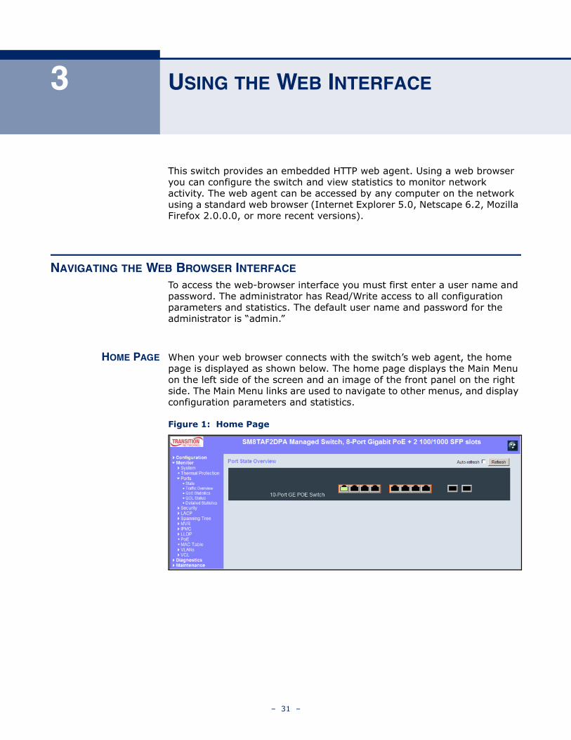
HOME PAGE When your web browser connects with the switch’s web agent, the home page is displayed as shown below. The home page displays the Main Menu on the left side of the screen and an image of the front panel on the right side. The Main Menu links are used to navigate to other menus, and display configuration parameters and statistics.
Figure 1: Home Page
– 31 –
CHAPTER 3 | Using the Web InterfaceNavigating the Web Browser Interface
CONFIGURATIONOPTIONS
Configurable parameters have a dialog box or a drop-down list. Once a configuration change has been made on a page, be sure to click on the Save button to confirm the new setting. The following table summarizes the web page configuration buttons.
NOTE: To ensure proper screen refresh, be sure that Internet Explorer is configured so that the setting “Check for newer versions of stored pages” reads “Every visit to the page.”
Internet Explorer 6.x and earlier: This option is available under the menu “Tools / Internet Options / General / Temporary Internet Files / Settings.”
Internet Explorer 7.x: This option is available under “Tools / Internet Options / General / Browsing History / Settings / Temporary Internet Files.”
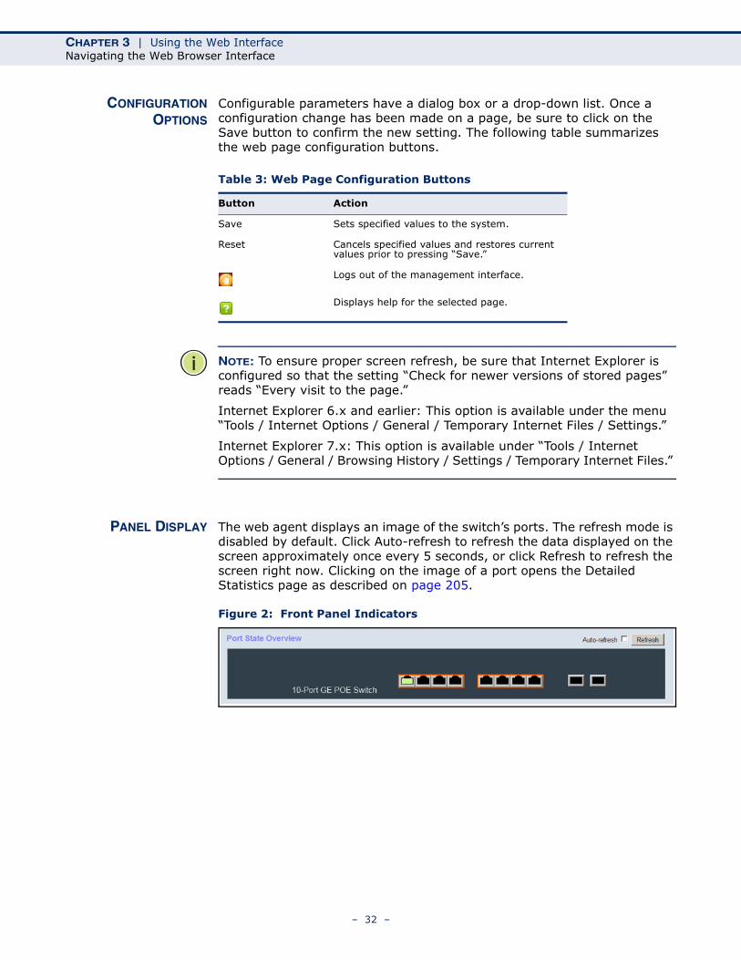
PANEL DISPLAY The web agent displays an image of the switch’s ports. The refresh mode is disabled by default. Click Auto-refresh to refresh the data displayed on the screen approximately once every 5 seconds, or click Refresh to refresh the screen right now. Clicking on the image of a port opens the Detailed Statistics page as described on page 205.
Figure 2: Front Panel Indicators
Table 3: Web Page Configuration Buttons
Button Action
Save Sets specified values to the system.
Reset Cancels specified values and restores current values prior to pressing “Save.”
Logs out of the management interface.
Displays help for the selected page.
– 32 –
CHAPTER 3 | Using the Web InterfaceNavigating the Web Browser Interface
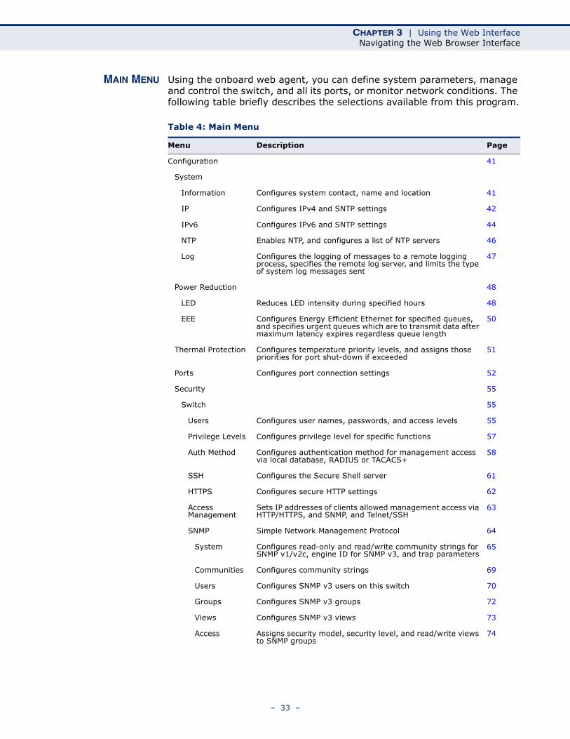
MAIN MENU Using the onboard web agent, you can define system parameters, manage and control the switch, and all its ports, or monitor network conditions. The following table briefly describes the selections available from this program.
Table 4: Main Menu
Menu Description Page
Configuration 41
System
Information Configures system contact, name and location 41
IP Configures IPv4 and SNTP settings 42
IPv6 Configures IPv6 and SNTP settings 44
NTP Enables NTP, and configures a list of NTP servers 46
Log Configures the logging of messages to a remote logging process, specifies the remote log server, and limits the type of system log messages sent
47
Power Reduction 48
LED Reduces LED intensity during specified hours 48
EEE Configures Energy Efficient Ethernet for specified queues, and specifies urgent queues which are to transmit data after maximum latency expires regardless queue length
50
Thermal Protection Configures temperature priority levels, and assigns those priorities for port shut-down if exceeded
51
Ports Configures port connection settings 52
Security 55
Switch 55
Users Configures user names, passwords, and access levels 55
Privilege Levels Configures privilege level for specific functions 57
Auth Method Configures authentication method for management access via local database, RADIUS or TACACS+
58
SSH Configures the Secure Shell server 61
HTTPS Configures secure HTTP settings 62
Access Management
Sets IP addresses of clients allowed management access via HTTP/HTTPS, and SNMP, and Telnet/SSH
63
SNMP Simple Network Management Protocol 64
System Configures read-only and read/write community strings for SNMP v1/v2c, engine ID for SNMP v3, and trap parameters
65
Communities Configures community strings 69
Users Configures SNMP v3 users on this switch 70
Groups Configures SNMP v3 groups 72
Views Configures SNMP v3 views 73
Access Assigns security model, security level, and read/write views to SNMP groups
74
– 33 –
CHAPTER 3 | Using the Web InterfaceNavigating the Web Browser Interface
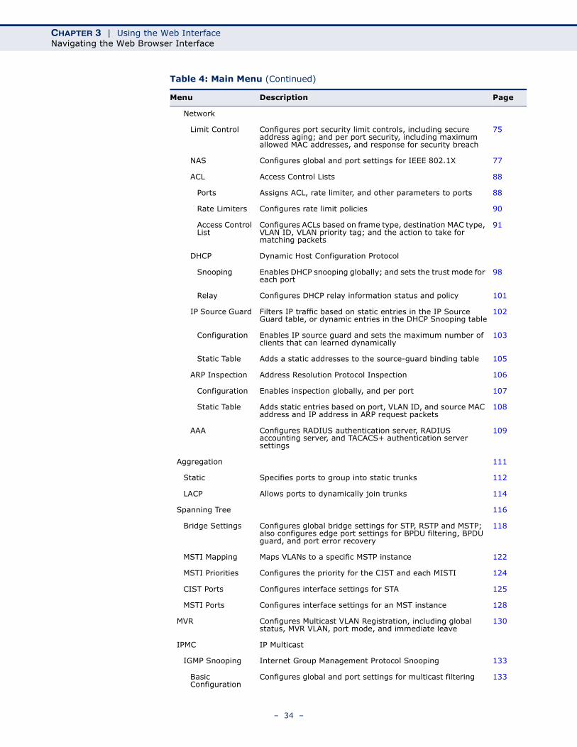
Network
Limit Control Configures port security limit controls, including secure address aging; and per port security, including maximum allowed MAC addresses, and response for security breach
75
NAS Configures global and port settings for IEEE 802.1X 77
ACL Access Control Lists 88
Ports Assigns ACL, rate limiter, and other parameters to ports 88
Rate Limiters Configures rate limit policies 90
Access Control List
Configures ACLs based on frame type, destination MAC type, VLAN ID, VLAN priority tag; and the action to take for matching packets
91
DHCP Dynamic Host Configuration Protocol
Snooping Enables DHCP snooping globally; and sets the trust mode for each port
98
Relay Configures DHCP relay information status and policy 101
IP Source Guard Filters IP traffic based on static entries in the IP Source Guard table, or dynamic entries in the DHCP Snooping table
102
Configuration Enables IP source guard and sets the maximum number of clients that can learned dynamically
103
Static Table Adds a static addresses to the source-guard binding table 105
ARP Inspection Address Resolution Protocol Inspection 106
Configuration Enables inspection globally, and per port 107
Static Table Adds static entries based on port, VLAN ID, and source MAC address and IP address in ARP request packets
108
AAA Configures RADIUS authentication server, RADIUS accounting server, and TACACS+ authentication server settings
109
Aggregation 111
Static Specifies ports to group into static trunks 112
LACP Allows ports to dynamically join trunks 114
Spanning Tree 116
Bridge Settings Configures global bridge settings for STP, RSTP and MSTP; also configures edge port settings for BPDU filtering, BPDU guard, and port error recovery
118
MSTI Mapping Maps VLANs to a specific MSTP instance 122
MSTI Priorities Configures the priority for the CIST and each MISTI 124
CIST Ports Configures interface settings for STA 125
MSTI Ports Configures interface settings for an MST instance 128
MVR Configures Multicast VLAN Registration, including global status, MVR VLAN, port mode, and immediate leave
130
IPMC IP Multicast
IGMP Snooping Internet Group Management Protocol Snooping 133
Basic Configuration
Configures global and port settings for multicast filtering 133
Table 4: Main Menu (Continued)
Menu Description Page
– 34 –
CHAPTER 3 | Using the Web InterfaceNavigating the Web Browser Interface
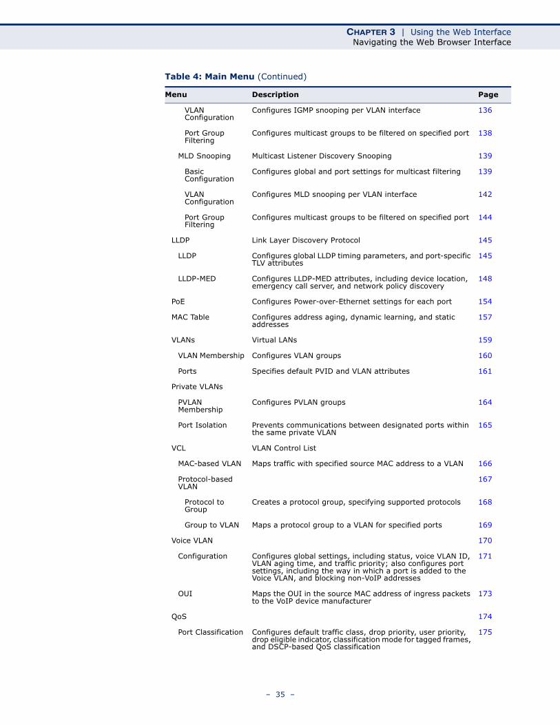
VLAN Configuration
Configures IGMP snooping per VLAN interface 136
Port Group Filtering
Configures multicast groups to be filtered on specified port 138
MLD Snooping Multicast Listener Discovery Snooping 139
Basic Configuration
Configures global and port settings for multicast filtering 139
VLAN Configuration
Configures MLD snooping per VLAN interface 142
Port Group Filtering
Configures multicast groups to be filtered on specified port 144
LLDP Link Layer Discovery Protocol 145
LLDP Configures global LLDP timing parameters, and port-specific TLV attributes
145
LLDP-MED Configures LLDP-MED attributes, including device location, emergency call server, and network policy discovery
148
PoE Configures Power-over-Ethernet settings for each port 154
MAC Table Configures address aging, dynamic learning, and static addresses
157
VLANs Virtual LANs 159
VLAN Membership Configures VLAN groups 160
Ports Specifies default PVID and VLAN attributes 161
Private VLANs
PVLAN Membership
Configures PVLAN groups 164
Port Isolation Prevents communications between designated ports within the same private VLAN
165
VCL VLAN Control List
MAC-based VLAN Maps traffic with specified source MAC address to a VLAN 166
Protocol-based VLAN
167
Protocol to Group
Creates a protocol group, specifying supported protocols 168
Group to VLAN Maps a protocol group to a VLAN for specified ports 169
Voice VLAN 170
Configuration Configures global settings, including status, voice VLAN ID, VLAN aging time, and traffic priority; also configures port settings, including the way in which a port is added to the Voice VLAN, and blocking non-VoIP addresses
171
OUI Maps the OUI in the source MAC address of ingress packets to the VoIP device manufacturer
173
QoS 174
Port Classification Configures default traffic class, drop priority, user priority, drop eligible indicator, classification mode for tagged frames, and DSCP-based QoS classification
175
Table 4: Main Menu (Continued)
Menu Description Page
– 35 –
CHAPTER 3 | Using the Web InterfaceNavigating the Web Browser Interface
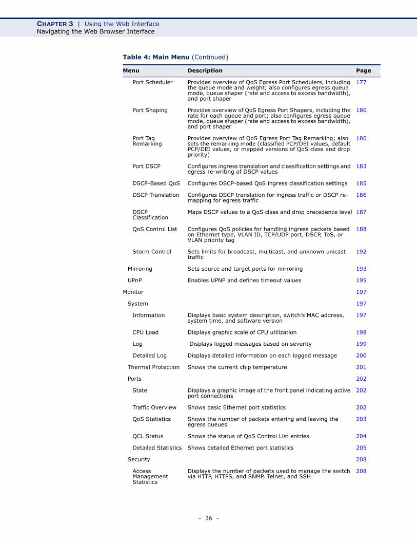
Port Scheduler Provides overview of QoS Egress Port Schedulers, including the queue mode and weight; also configures egress queue mode, queue shaper (rate and access to excess bandwidth), and port shaper
177
Port Shaping Provides overview of QoS Egress Port Shapers, including the rate for each queue and port; also configures egress queue mode, queue shaper (rate and access to excess bandwidth), and port shaper
180
Port Tag Remarking
Provides overview of QoS Egress Port Tag Remarking; also sets the remarking mode (classified PCP/DEI values, default PCP/DEI values, or mapped versions of QoS class and drop priority)
180
Port DSCP Configures ingress translation and classification settings and egress re-writing of DSCP values
183
DSCP-Based QoS Configures DSCP-based QoS ingress classification settings 185
DSCP Translation Configures DSCP translation for ingress traffic or DSCP re-mapping for egress traffic
186
DSCP Classification
Maps DSCP values to a QoS class and drop precedence level 187
QoS Control List Configures QoS policies for handling ingress packets based on Ethernet type, VLAN ID, TCP/UDP port, DSCP, ToS, or VLAN priority tag
188
Storm Control Sets limits for broadcast, multicast, and unknown unicast traffic
192
Mirroring Sets source and target ports for mirroring 193
UPnP Enables UPNP and defines timeout values 195
Monitor 197
System 197
Information Displays basic system description, switch’s MAC address, system time, and software version
197
CPU Load Displays graphic scale of CPU utilization 198
Log Displays logged messages based on severity 199
Detailed Log Displays detailed information on each logged message 200
Thermal Protection Shows the current chip temperature 201
Ports 202
State Displays a graphic image of the front panel indicating active port connections
202
Traffic Overview Shows basic Ethernet port statistics 202
QoS Statistics Shows the number of packets entering and leaving the egress queues
203
QCL Status Shows the status of QoS Control List entries 204
Detailed Statistics Shows detailed Ethernet port statistics 205
Security 208
Access Management Statistics
Displays the number of packets used to manage the switch via HTTP, HTTPS, and SNMP, Telnet, and SSH
208
Table 4: Main Menu (Continued)
Menu Description Page
– 36 –

CHAPTER 3 | Using the Web InterfaceNavigating the Web Browser Interface
Network
Port Security
Switch Shows information about MAC address learning for each port, including the software module requesting port security services, the service state, the current number of learned addresses, and the maximum number of secure addresses allowed
209
Port Shows the entries authorized by port security services, including MAC address, VLAN ID, the service state, time added to table, age, and hold state
211
NAS Shows global and port settings for IEEE 802.1X
Switch Shows port status for authentication services, including 802.1X security state, last source address used for authentication, and last ID
212
Port Displays authentication statistics for the selected port – either for 802.1X protocol or for the remote authentication server depending on the authentication method
213
ACL Status Shows the status for different security modules which use ACL filtering, including ingress port, frame type, and forwarding action
217
DHCP Dynamic Host Configuration Protocol
Snooping Statistics
Shows statistics for various types of DHCP protocol packets 219
Relay Statistics
Displays server and client statistics for packets affected by the relay information policy
220
ARP Inspection Displays entries in the ARP inspection table, sorted first by port, then VLAN ID, MAC address, and finally IP address
221
IP Source Guard Displays entries in the IP Source Guard table, sorted first by port, then VLAN ID, MAC address, and finally IP address
222
AAA Authentication, Authorization and Accounting 223
RADIUS Overview
Displays status of configured RADIUS authentication and accounting servers
223
RADIUS Details Displays the traffic and status associated with each configured RADIUS server
224
LACP Link Aggregation Control Protocol 227
System Status Displays administration key and associated local ports for each partner
227
Port Status Displays administration key, LAG ID, partner ID, and partner ports for each local port
228
Port Statistics Displays statistics for LACP protocol messages 229
Spanning Tree 230
Bridge Status Displays global bridge and port settings for STA 230
Port Status Displays STA role, state, and uptime for each port 232
Port Statistics Displays statistics for RSTP, STP and TCN protocol packets 233
MVR Multicast VLAN Registration 234
Statistics Shows statistics for IGMP protocol messages used by MVR 234
Table 4: Main Menu (Continued)
Menu Description Page
– 37 –
CHAPTER 3 | Using the Web InterfaceNavigating the Web Browser Interface
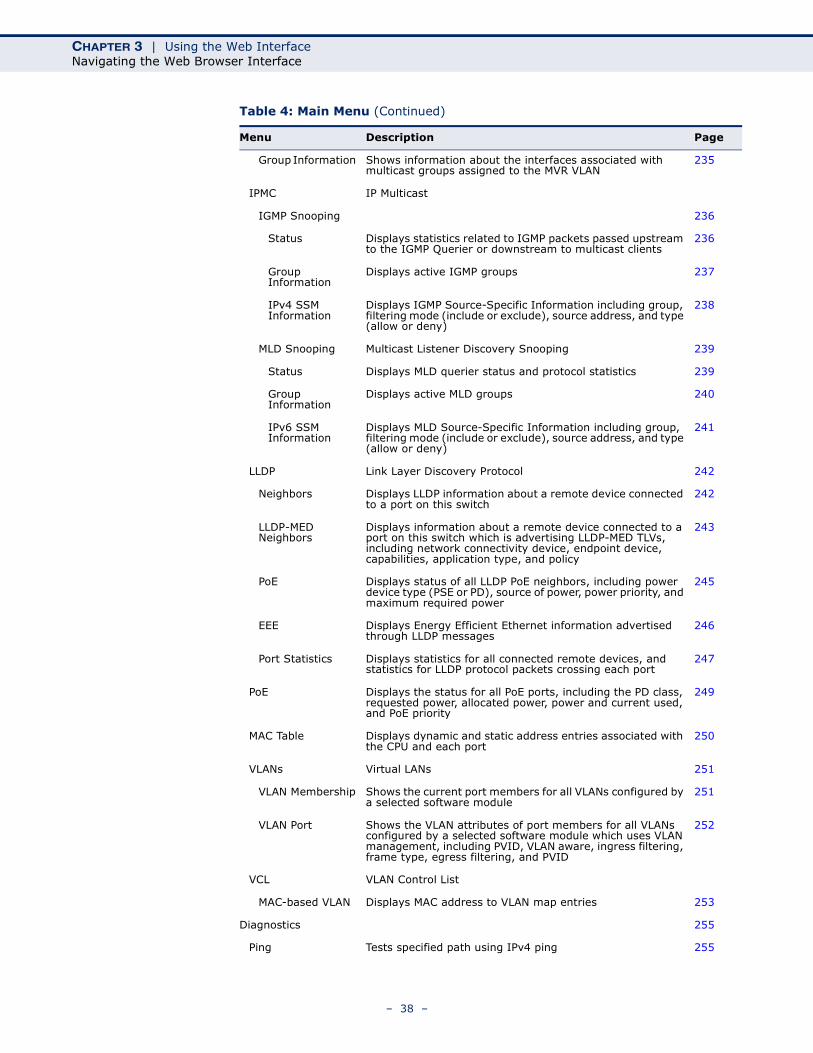
Group Information Shows information about the interfaces associated with multicast groups assigned to the MVR VLAN
235
IPMC IP Multicast
IGMP Snooping 236
Status Displays statistics related to IGMP packets passed upstream to the IGMP Querier or downstream to multicast clients
236
Group Information
Displays active IGMP groups 237
IPv4 SSM Information
Displays IGMP Source-Specific Information including group, filtering mode (include or exclude), source address, and type (allow or deny)
238
MLD Snooping Multicast Listener Discovery Snooping 239
Status Displays MLD querier status and protocol statistics 239
Group Information
Displays active MLD groups 240
IPv6 SSM Information
Displays MLD Source-Specific Information including group, filtering mode (include or exclude), source address, and type (allow or deny)
241
LLDP Link Layer Discovery Protocol 242
Neighbors Displays LLDP information about a remote device connected to a port on this switch
242
LLDP-MED Neighbors
Displays information about a remote device connected to a port on this switch which is advertising LLDP-MED TLVs, including network connectivity device, endpoint device, capabilities, application type, and policy
243
PoE Displays status of all LLDP PoE neighbors, including power device type (PSE or PD), source of power, power priority, and maximum required power
245
EEE Displays Energy Efficient Ethernet information advertised through LLDP messages
246
Port Statistics Displays statistics for all connected remote devices, and statistics for LLDP protocol packets crossing each port
247
PoE Displays the status for all PoE ports, including the PD class, requested power, allocated power, power and current used, and PoE priority
249
MAC Table Displays dynamic and static address entries associated with the CPU and each port
250
VLANs Virtual LANs 251
VLAN Membership Shows the current port members for all VLANs configured by a selected software module
251
VLAN Port Shows the VLAN attributes of port members for all VLANs configured by a selected software module which uses VLAN management, including PVID, VLAN aware, ingress filtering, frame type, egress filtering, and PVID
252
VCL VLAN Control List
MAC-based VLAN Displays MAC address to VLAN map entries 253
Diagnostics 255
Ping Tests specified path using IPv4 ping 255
Table 4: Main Menu (Continued)
Menu Description Page
– 38 –
CHAPTER 3 | Using the Web InterfaceNavigating the Web Browser Interface
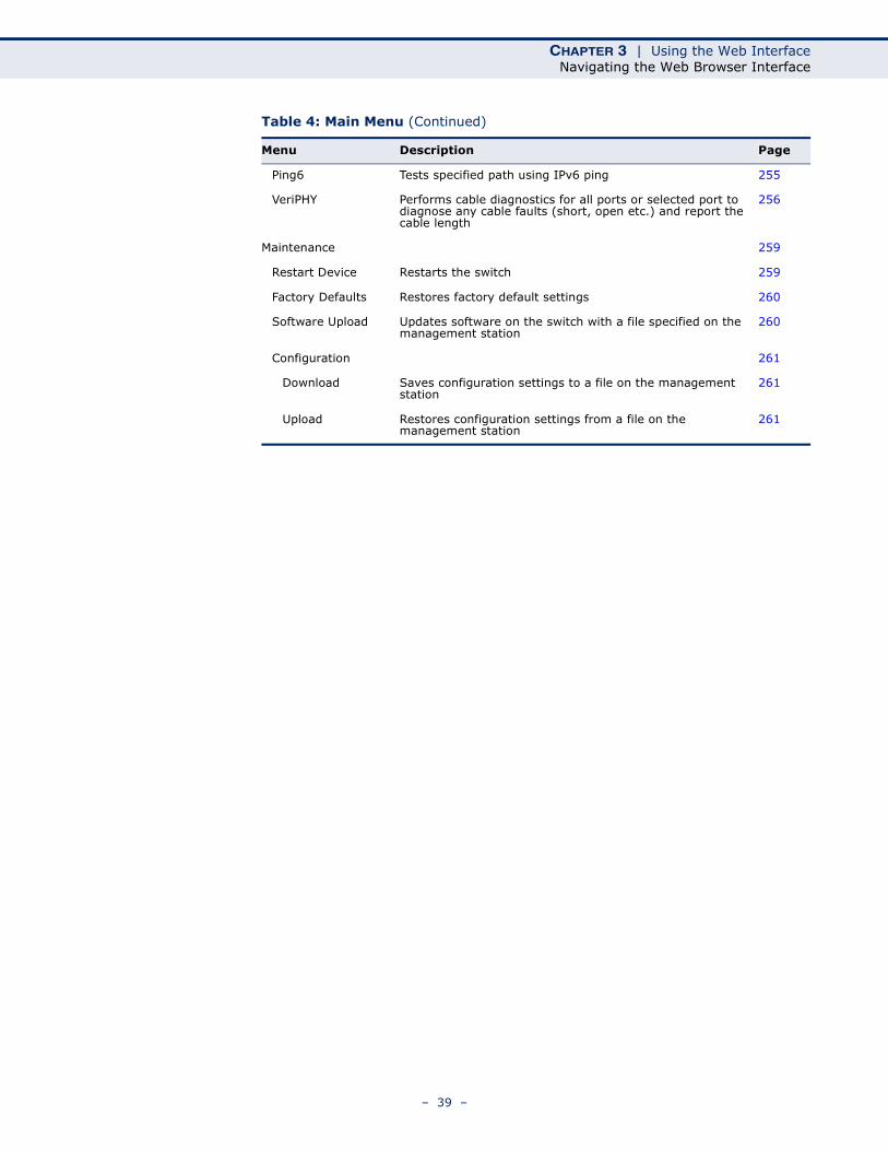
Ping6 Tests specified path using IPv6 ping 255
VeriPHY Performs cable diagnostics for all ports or selected port to diagnose any cable faults (short, open etc.) and report the cable length
256
Maintenance 259
Restart Device Restarts the switch 259
Factory Defaults Restores factory default settings 260
Software Upload Updates software on the switch with a file specified on the management station
260
Configuration 261
Download Saves configuration settings to a file on the management station
261
Upload Restores configuration settings from a file on the management station
261
Table 4: Main Menu (Continued)
Menu Description Page
– 39 –

CHAPTER 3 | Using the Web InterfaceNavigating the Web Browser Interface
– 40 –
4 CONFIGURING THE SWITCH
This chapter describes all of the basic configuration tasks.
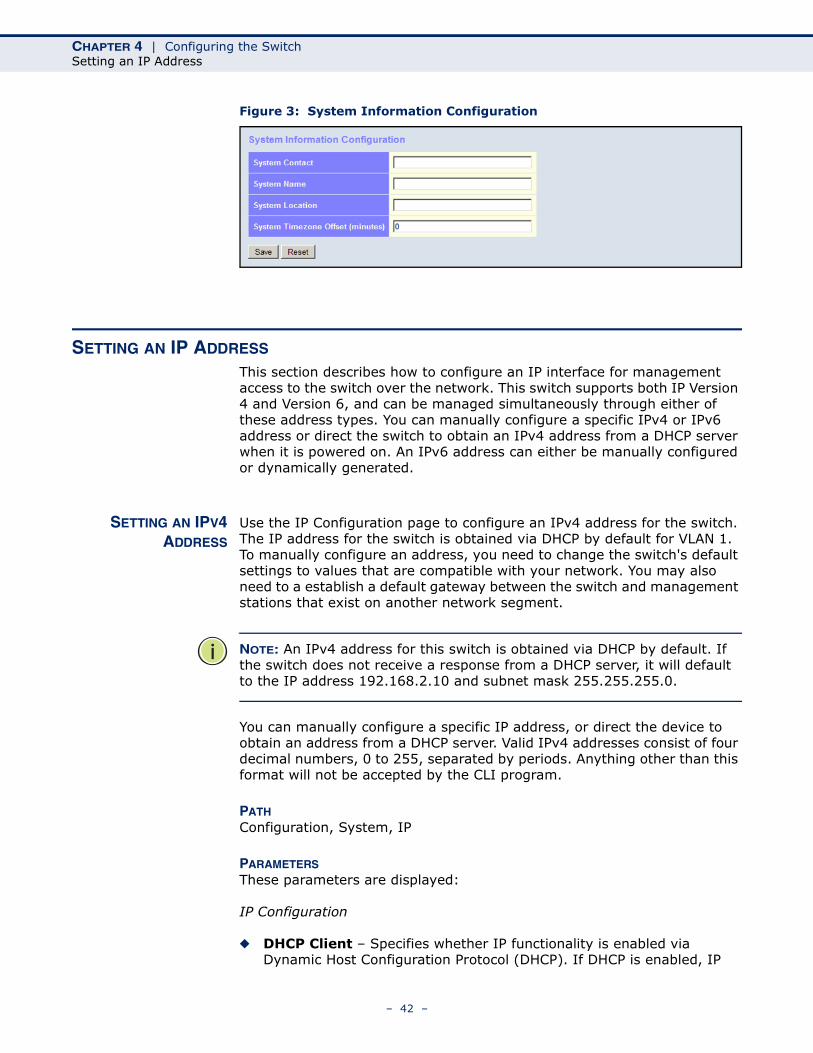
CONFIGURING SYSTEM INFORMATION
Use the System Information Configuration page to identify the system by configuring contact information, system name, location of the switch, and time zone offset.
PATH Configuration, System, Information
PARAMETERSThese parameters are displayed:
◆ System Contact – Administrator responsible for the system. (Maximum length: 255 characters)
◆ System Name – Name assigned to the switch system. (Maximum length: 255 characters)
◆ System Location – Specifies the system location. (Maximum length: 255 characters)
◆ System Timezone Offset (minutes) – Sets the time zone as an offset from Greenwich Mean Time (GMT). Negative values indicate a zone before (east of) GMT, and positive values indicate a zone after (west of) GMT.
WEB INTERFACETo configure System Information:
1. Click Configuration, System, Information.
2. Specify the contact information for the system administrator, as well as the name and location of the switch. Also indicate the local time zone by configuring the appropriate offset.
3. Click Save.
– 41 –
CHAPTER 4 | Configuring the SwitchSetting an IP Address
Figure 3: System Information Configuration
SETTING AN IP ADDRESS
This section describes how to configure an IP interface for management access to the switch over the network. This switch supports both IP Version 4 and Version 6, and can be managed simultaneously through either of these address types. You can manually configure a specific IPv4 or IPv6 address or direct the switch to obtain an IPv4 address from a DHCP server when it is powered on. An IPv6 address can either be manually configured or dynamically generated.
SETTING AN IPV4ADDRESS
Use the IP Configuration page to configure an IPv4 address for the switch. The IP address for the switch is obtained via DHCP by default for VLAN 1. To manually configure an address, you need to change the switch's default settings to values that are compatible with your network. You may also need to a establish a default gateway between the switch and management stations that exist on another network segment.
NOTE: An IPv4 address for this switch is obtained via DHCP by default. If the switch does not receive a response from a DHCP server, it will default to the IP address 192.168.2.10 and subnet mask 255.255.255.0.
You can manually configure a specific IP address, or direct the device to obtain an address from a DHCP server. Valid IPv4 addresses consist of four decimal numbers, 0 to 255, separated by periods. Anything other than this format will not be accepted by the CLI program.
PATH Configuration, System, IP
PARAMETERSThese parameters are displayed:
IP Configuration
◆ DHCP Client – Specifies whether IP functionality is enabled via Dynamic Host Configuration Protocol (DHCP). If DHCP is enabled, IP
– 42 –
CHAPTER 4 | Configuring the SwitchSetting an IP Address
will not function until a reply has been received from the server. Requests will be broadcast periodically by the switch for an IP address. DHCP values can include the IP address, subnet mask, and default gateway. (Default: Enabled)
◆ IP Address – Address of the VLAN specified in the VLAN ID field. This should be the VLAN to which the management station is attached. Valid IP addresses consist of four numbers, 0 to 255, separated by periods. (Default: 192.168.2.10)
◆ IP Mask – This mask identifies the host address bits used for routing to specific subnets. (Default: 255.255.255.0)
◆ IP Router – IP address of the gateway router between the switch and management stations that exist on other network segments.
◆ VLAN ID – ID of the configured VLAN. By default, all ports on the switch are members of VLAN 1. However, the management station can be attached to a port belonging to any VLAN, as long as that VLAN has been assigned an IP address. (Range: 1-4095; Default: 1)
◆ DNS Server – A Domain Name Server to which client requests for mapping host names to IP addresses are forwarded.
IP DNS Proxy Configuration
◆ DNS Proxy – If enabled, the switch maintains a local database based on previous responses to DNS queries forwarded on behalf of attached clients. If the required information is not in the local database, the switch forwards the DNS query to a DNS server, stores the response in its local cache for future reference, and passes the response back to the client.
WEB INTERFACETo configure an IP address:
1. Click Configuration, System, IP.
2. Specify the IPv4 settings, and enable DNS proxy service if required.
3. Click Save.
– 43 –
CHAPTER 4 | Configuring the SwitchSetting an IP Address
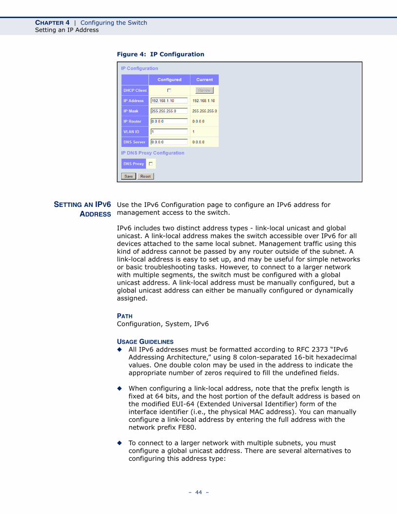
Figure 4: IP Configuration
SETTING AN IPV6ADDRESS
Use the IPv6 Configuration page to configure an IPv6 address for management access to the switch.
IPv6 includes two distinct address types - link-local unicast and global unicast. A link-local address makes the switch accessible over IPv6 for all devices attached to the same local subnet. Management traffic using this kind of address cannot be passed by any router outside of the subnet. A link-local address is easy to set up, and may be useful for simple networks or basic troubleshooting tasks. However, to connect to a larger network with multiple segments, the switch must be configured with a global unicast address. A link-local address must be manually configured, but a global unicast address can either be manually configured or dynamically assigned.
PATH Configuration, System, IPv6
USAGE GUIDELINES◆ All IPv6 addresses must be formatted according to RFC 2373 “IPv6
Addressing Architecture,” using 8 colon-separated 16-bit hexadecimal values. One double colon may be used in the address to indicate the appropriate number of zeros required to fill the undefined fields.
◆ When configuring a link-local address, note that the prefix length is fixed at 64 bits, and the host portion of the default address is based on the modified EUI-64 (Extended Universal Identifier) form of the interface identifier (i.e., the physical MAC address). You can manually configure a link-local address by entering the full address with the network prefix FE80.
◆ To connect to a larger network with multiple subnets, you must configure a global unicast address. There are several alternatives to configuring this address type:
– 44 –

CHAPTER 4 | Configuring the SwitchSetting an IP Address
■ The global unicast address can be automatically configured by taking the network prefix from router advertisements observed on the local interface, and using the modified EUI-64 form of the interface identifier to automatically create the host portion of the address. This option can be selected by enabling the Auto Configuration option.
■ You can also manually configure the global unicast address by entering the full address and prefix length.
◆ The management VLAN to which the IPv6 address is assigned must be specified on the IP Configuration page. See "Setting an IPv4 Address" on page 42.
PARAMETERSThese parameters are displayed:
◆ Auto Configuration – Enables stateless autoconfiguration of IPv6 addresses on an interface and enables IPv6 functionality on the interface. The network portion of the address is based on prefixes received in IPv6 router advertisement messages, and the host portion is automatically generated using the modified EUI-64 form of the interface identifier; i.e., the switch's MAC address. (Default: Disabled)
◆ Address – Manually configures a global unicast address by specifying the full address and network prefix length (in the Prefix field). (Default: ::192.168.2.10)
◆ Prefix – Defines the prefix length as a decimal value indicating how many contiguous bits (starting at the left) of the address comprise the prefix; i.e., the network portion of the address. (Default: 96 bits)
Note that the default prefix length of 96 bits specifies that the first six colon-separated values comprise the network portion of the address.
◆ Router – Sets the IPv6 address of the default next hop router.
An IPv6 default gateway must be defined if the management station is located in a different IPv6 segment.
An IPv6 default gateway can only be successfully set when a network interface that directly connects to the gateway has been configured on the switch.
WEB INTERFACETo configure an IPv6 address:
1. Click Configuration, System, IPv6.
2. Specify the IPv6 settings. The information shown below provides a example of how to manually configure an IPv6 address.
3. Click Save.
– 45 –
CHAPTER 4 | Configuring the SwitchConfiguring NTP Service
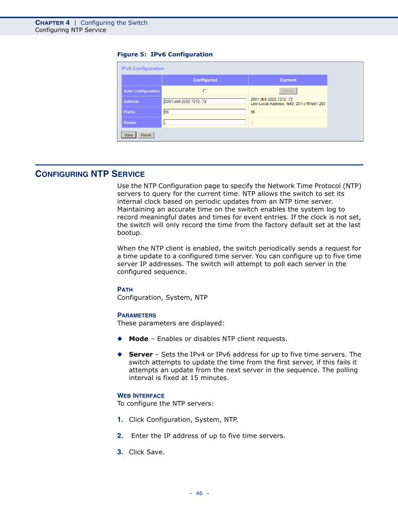
Figure 5: IPv6 Configuration
CONFIGURING NTP SERVICE
Use the NTP Configuration page to specify the Network Time Protocol (NTP) servers to query for the current time. NTP allows the switch to set its internal clock based on periodic updates from an NTP time server. Maintaining an accurate time on the switch enables the system log to record meaningful dates and times for event entries. If the clock is not set, the switch will only record the time from the factory default set at the last bootup.
When the NTP client is enabled, the switch periodically sends a request for a time update to a configured time server. You can configure up to five time server IP addresses. The switch will attempt to poll each server in the configured sequence.
PATH Configuration, System, NTP
PARAMETERSThese parameters are displayed:
◆ Mode – Enables or disables NTP client requests.
◆ Server – Sets the IPv4 or IPv6 address for up to five time servers. The switch attempts to update the time from the first server, if this fails it attempts an update from the next server in the sequence. The polling interval is fixed at 15 minutes.
WEB INTERFACETo configure the NTP servers:
1. Click Configuration, System, NTP.
2. Enter the IP address of up to five time servers.
3. Click Save.
– 46 –
CHAPTER 4 | Configuring the SwitchConfiguring Remote Log Messages
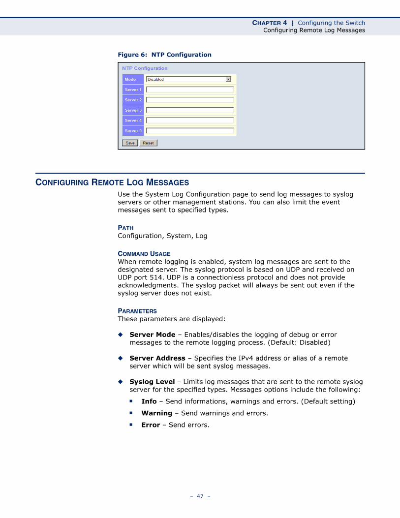
Figure 6: NTP Configuration
CONFIGURING REMOTE LOG MESSAGES
Use the System Log Configuration page to send log messages to syslog servers or other management stations. You can also limit the event messages sent to specified types.
PATH Configuration, System, Log
COMMAND USAGEWhen remote logging is enabled, system log messages are sent to the designated server. The syslog protocol is based on UDP and received on UDP port 514. UDP is a connectionless protocol and does not provide acknowledgments. The syslog packet will always be sent out even if the syslog server does not exist.
PARAMETERSThese parameters are displayed:
◆ Server Mode – Enables/disables the logging of debug or error messages to the remote logging process. (Default: Disabled)
◆ Server Address – Specifies the IPv4 address or alias of a remote server which will be sent syslog messages.
◆ Syslog Level – Limits log messages that are sent to the remote syslog server for the specified types. Messages options include the following:
■ Info – Send informations, warnings and errors. (Default setting)
■ Warning – Send warnings and errors.
■ Error – Send errors.
– 47 –
CHAPTER 4 | Configuring the SwitchConfiguring Power Reduction
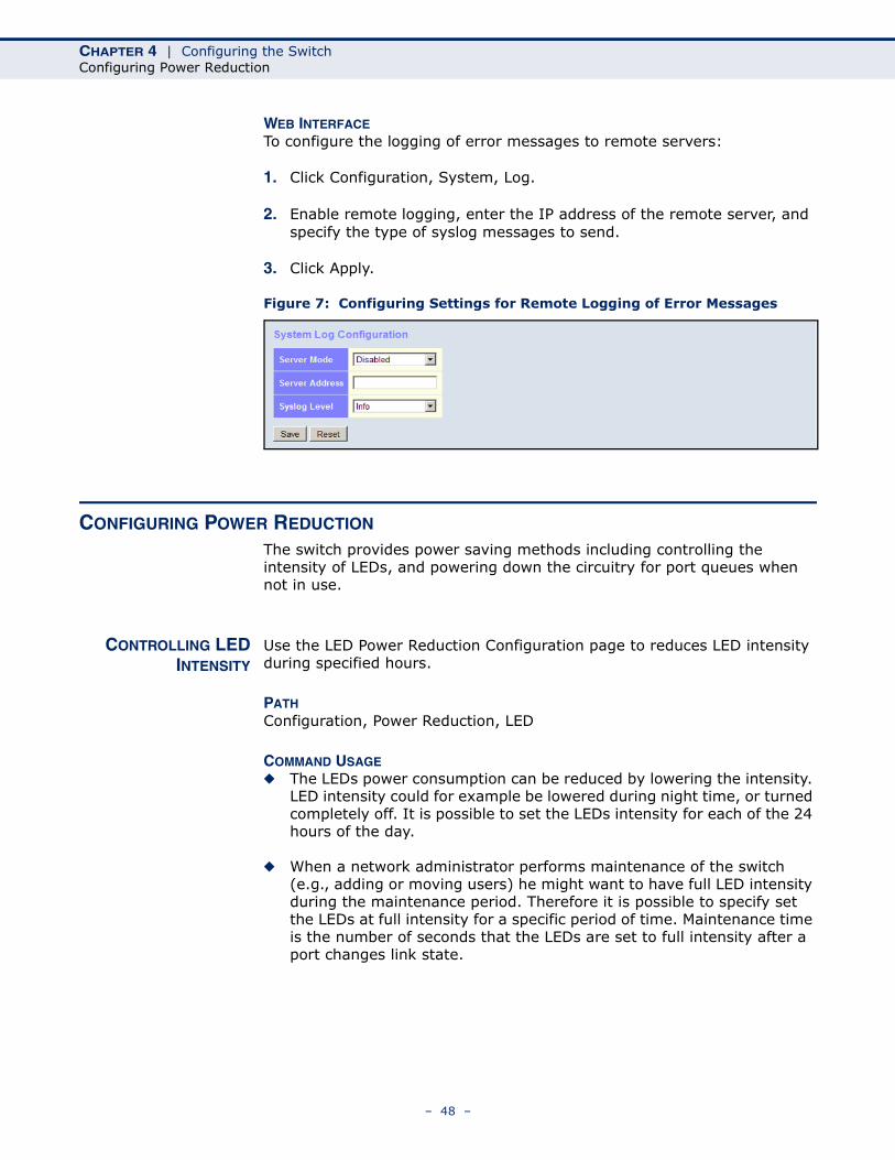
WEB INTERFACETo configure the logging of error messages to remote servers:
1. Click Configuration, System, Log.
2. Enable remote logging, enter the IP address of the remote server, and specify the type of syslog messages to send.
3. Click Apply.
Figure 7: Configuring Settings for Remote Logging of Error Messages
CONFIGURING POWER REDUCTION
The switch provides power saving methods including controlling the intensity of LEDs, and powering down the circuitry for port queues when not in use.
CONTROLLING LEDINTENSITY
Use the LED Power Reduction Configuration page to reduces LED intensity during specified hours.
PATH Configuration, Power Reduction, LED
COMMAND USAGE◆ The LEDs power consumption can be reduced by lowering the intensity.
LED intensity could for example be lowered during night time, or turned completely off. It is possible to set the LEDs intensity for each of the 24 hours of the day.
◆ When a network administrator performs maintenance of the switch (e.g., adding or moving users) he might want to have full LED intensity during the maintenance period. Therefore it is possible to specify set the LEDs at full intensity for a specific period of time. Maintenance time is the number of seconds that the LEDs are set to full intensity after a port changes link state.
– 48 –
CHAPTER 4 | Configuring the SwitchConfiguring Power Reduction
PARAMETERSThese parameters are displayed:
LED Intensity Timers
◆ Time – Time at which LED intensity is set.
◆ Intensity – LED intensity (Range: 0-100%, in increments of 10%, where 0% means off and 100% means full power)
Maintenance
◆ On time at link change – LEDs set at full intensity for a specified period when a link change occurs. (Default: 10 seconds)
◆ On at errors – LEDs set at full intensity when a link error occurs.
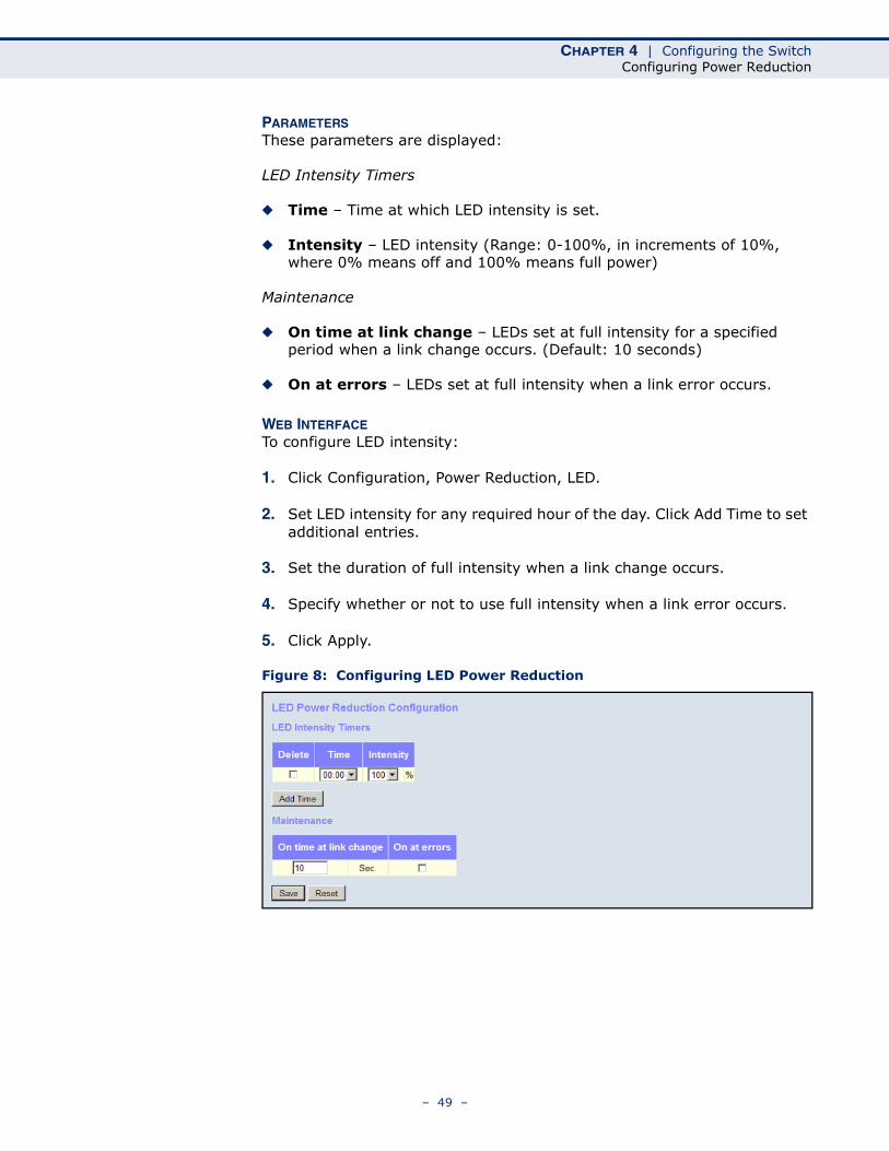
WEB INTERFACETo configure LED intensity:
1. Click Configuration, Power Reduction, LED.
2. Set LED intensity for any required hour of the day. Click Add Time to set additional entries.
3. Set the duration of full intensity when a link change occurs.
4. Specify whether or not to use full intensity when a link error occurs.
5. Click Apply.
Figure 8: Configuring LED Power Reduction
– 49 –
CHAPTER 4 | Configuring the SwitchConfiguring Power Reduction
REDUCING POWER TOIDLE QUEUE CIRCUITS
Use the EEE Configuration page to configure Energy Efficient Ethernet (EEE) for specified queues, and to specify urgent queues which are to transmit data after maximum latency expires regardless of queue length.
PATH Configuration, Power Reduction, EEE
COMMAND USAGE ◆ EEE works by powering down circuits when there is no traffic. When a
port gets data to be transmitted all relevant circuits are powered up. The time it takes to power up the circuits is call the wakeup time. The default wakeup time is 17 µs for 1 Gbps links and 30 µs for other link speeds. EEE devices must agree upon the value of the wakeup time in order to make sure that both the receiving and transmitting devices have all circuits powered up when traffic is transmitted. The devices can exchange information about the device wakeup time using LLDP protocol.
To maximize power savings, the circuit is not started as soon as data is ready to be transmitted from a port, but instead waits until 3000 bytes of data is queued at the port. To avoid introducing a large delay when the queued data is less then 3000 bytes, data is always transmitted after 48 µs, giving a maximum latency of 48 µs plus the wakeup time.
◆ If required, it is possible to minimize the latency for specific frames by mapping the frames to a specific queue (EEE Urgent Queues). When an urgent queue gets data to be transmitted, the circuits will be powered up at once and the latency will be reduced to the wakeup time.
PARAMETERSThese parameters are displayed:
◆ Port – Port identifier.
◆ EEE Enabled – Enables or disables EEE for the specified port.
◆ EEE Urgent Queues – Specifies which are to transmit data after the maximum latency expires regardless queue length.
WEB INTERFACETo configure the power reduction for idle queue circuits:
1. Click Configuration, Power Reduction, EEE.
2. Select the circuits which will use EEE.
3. If required, also specify urgent queues which will be powered up once data is queued and the default wakeup time has passed.
4. Click Save.
– 50 –

CHAPTER 4 | Configuring the SwitchConfiguring Thermal Protection
Figure 9: Configuring EEE Power Reduction
CONFIGURING THERMAL PROTECTION
Use the Thermal Protection Configuration page to set temperature priority levels, and assign those priorities for port shut-down if exceeded.
PATH Configuration, Thermal Protection
COMMAND USAGE Thermal protection is used to protect the switch ASIC from overheating. When the internal temperature of the switch exceeds a specified protection level, ports can be turned off to decrease power consumption. Port shut down can be prioritized based on assigned temperatures.
PARAMETERSThese parameters are displayed:
Temperature settings for priority groups
◆ Priority – A priority assigned to a specific temperature. (Range: 0-3)
◆ Temperature – The temperature at which the ports with the corresponding priority will be turned off. (Range: 0-255° C)
Port priorities
◆ Port – Port identifier.
◆ Priority – The priority level at which to shut down a port. (Range: 0-3)
– 51 –
CHAPTER 4 | Configuring the SwitchConfiguring Port Connections
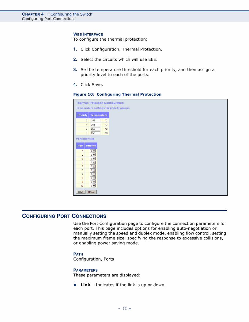
WEB INTERFACETo configure the thermal protection:
1. Click Configuration, Thermal Protection.
2. Select the circuits which will use EEE.
3. Se the temperature threshold for each priority, and then assign a priority level to each of the ports.
4. Click Save.
Figure 10: Configuring Thermal Protection
CONFIGURING PORT CONNECTIONS
Use the Port Configuration page to configure the connection parameters for each port. This page includes options for enabling auto-negotiation or manually setting the speed and duplex mode, enabling flow control, setting the maximum frame size, specifying the response to excessive collisions, or enabling power saving mode.
PATH Configuration, Ports
PARAMETERSThese parameters are displayed:
◆ Link – Indicates if the link is up or down.
– 52 –
CHAPTER 4 | Configuring the SwitchConfiguring Port Connections
◆ Speed – Sets the port speed and duplex mode using auto-negotiation or manual selection. The following options are supported:
■ Disabled - Disables the interface. You can disable an interface due to abnormal behavior (e.g., excessive collisions), and then re-enable it after the problem has been resolved. You may also disable an interface for security reasons.
■ Auto - Enables auto-negotiation. When using auto-negotiation, the optimal settings will be negotiated between the link partners based on their advertised capabilities.
■ 1Gbps FDX - Supports 1 Gbps full-duplex operation
■ 100Mbps FDX - Supports 100 Mbps full-duplex operation
■ 100Mbps HDX - Supports 100 Mbps half-duplex operation
■ 10Mbps FDX - Supports 10 Mbps full-duplex operation
■ 10Mbps HDX - Supports 10 Mbps half-duplex operation
(Default: Autonegotiation enabled; Advertised capabilities for RJ-45: 1000BASE-T - 10half, 10full, 100half, 100full, 1000full; SFP: 1000BASE-SX/LX/LH - 1000full)
NOTE: The 1000BASE-T standard does not support forced mode. Auto-negotiation should always be used to establish a connection over any 1000BASE-T port or trunk. If not used, the success of the link process cannot be guaranteed when connecting to other types of switches.
◆ Flow Control – Flow control can eliminate frame loss by “blocking” traffic from end stations or segments connected directly to the switch when its buffers fill. When enabled, back pressure is used for half-duplex operation and IEEE 802.3-2005 (formally IEEE 802.3x) for full-duplex operation. (Default: Disabled)
When auto-negotiation is used, this parameter indicates the flow control capability advertised to the link partner. When the speed and duplex mode are manually set, the Current Rx field indicates whether pause frames are obeyed by this port, and the Current Tx field indicates if pause frames are transmitted from this port.
Avoid using flow control on a port connected to a hub unless it is actually required to solve a problem. Otherwise back pressure jamming signals may degrade overall performance for the segment attached to the hub.
◆ Maximum Frame Size – Sets the maximum transfer unit for traffic crossing the switch. Packets exceeding the maximum frame size are dropped. (Range: 9600-1518 bytes; Default: 9600 bytes)
◆ Excessive Collision Mode – Sets the response to take when excessive transmit collisions are detected on a port.
■ Discard - Discards a frame after 16 collisions (default).
■ Restart - Restarts the backoff algorithm after 16 collisions.
– 53 –
CHAPTER 4 | Configuring the SwitchConfiguring Port Connections
◆ Power Control – Adjusts the power provided to ports based on the length of the cable used to connect to other devices. Only sufficient power is used to maintain connection requirements.
IEEE 802.3 defines the Ethernet standard and subsequent power requirements based on cable connections operating at 100 meters. Enabling power saving mode can significantly reduce power used for cable lengths of 20 meters or less, and continue to ensure signal integrity.
The following options are supported:
■ Disabled – All power savings mechanisms disabled (default).
■ Enabled – Both link up and link down power savings enabled.
■ ActiPHY – Link down power savings enabled.
■ PerfectReach – Link up power savings enabled.
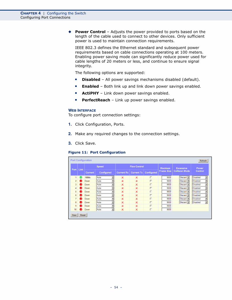
WEB INTERFACETo configure port connection settings:
1. Click Configuration, Ports.
2. Make any required changes to the connection settings.
3. Click Save.
Figure 11: Port Configuration
– 54 –
CHAPTER 4 | Configuring the SwitchConfiguring Security
CONFIGURING SECURITY
You can configure this switch to authenticate users logging into the system for management access or to control client access to the data ports.
Management Access Security (Switch menu) – Management access to the switch can be controlled through local authentication of user names and passwords stored on the switch, or remote authentication of users via a RADIUS or TACACS+ server. Additional authentication methods includes Secure Shell (SSH), Secure Hypertext Transfer Protocol (HTTPS) over the Secure Socket Layer (SSL), static configuration of client addresses, and SNMP.
General Security Measures (Network menu) – This switch supports many methods of segregating traffic for clients attached to each of the data ports, and for ensuring that only authorized clients gain access to the network. Private VLANs and port-based authentication using IEEE 802.1X are commonly used for these purposes. In addition to these methods, several other options of providing client security are supported by this switch. These include limiting the number of users accessing a port. The addresses assigned to DHCP clients can also be carefully controlled using static or dynamic bindings with DHCP Snooping and IP Source Guard commands. ARP Inspection can also be used to validate the MAC address bindings for ARP packets, providing protection against ARP traffic with invalid MAC to IP address bindings, which forms the basis for “man-in-the-middle” attacks.
CONFIGURING USERACCOUNTS
Use the User Configuration page to control management access to the switch based on manually configured user names and passwords.
PATH Configuration, Security, Switch, Users
COMMAND USAGE◆ The default guest name is “guest” with the password “guest.” The
default administrator name is “admin” with the password “admin.”
◆ The guest only has read access for most configuration parameters. However, the administrator has write access for all parameters governing the onboard agent. You should therefore assign a new administrator password as soon as possible, and store it in a safe place.
◆ The administrator has a privilege level of 15, with access to all process groups and full control over the device. If the privilege level is set to any other value, the system will refer to each group privilege level. The user's privilege should be same or greater than the group privilege level to have the access of a group. By default, most of the group privilege levels are set to 5 which provides read-only access and privilege level 10 which also provides read/write access. To perform system maintenance (software upload, factory defaults, etc.) the user’s privilege level should be set to 15. Generally, the privilege level 15 can
– 55 –
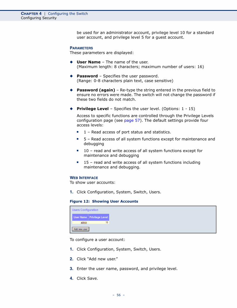
CHAPTER 4 | Configuring the SwitchConfiguring Security
be used for an administrator account, privilege level 10 for a standard user account, and privilege level 5 for a guest account.
PARAMETERSThese parameters are displayed:
◆ User Name – The name of the user.(Maximum length: 8 characters; maximum number of users: 16)
◆ Password – Specifies the user password.(Range: 0-8 characters plain text, case sensitive)
◆ Password (again) – Re-type the string entered in the previous field to ensure no errors were made. The switch will not change the password if these two fields do not match.
◆ Privilege Level – Specifies the user level. (Options: 1 - 15)
Access to specific functions are controlled through the Privilege Levels configuration page (see page 57). The default settings provide four access levels:
■ 1 – Read access of port status and statistics.
■ 5 – Read access of all system functions except for maintenance and debugging
■ 10 – read and write access of all system functions except for maintenance and debugging
■ 15 – read and write access of all system functions including maintenance and debugging.
WEB INTERFACETo show user accounts:
1. Click Configuration, System, Switch, Users.
Figure 12: Showing User Accounts
To configure a user account:
1. Click Configuration, System, Switch, Users.
2. Click “Add new user.”
3. Enter the user name, password, and privilege level.
4. Click Save.
– 56 –
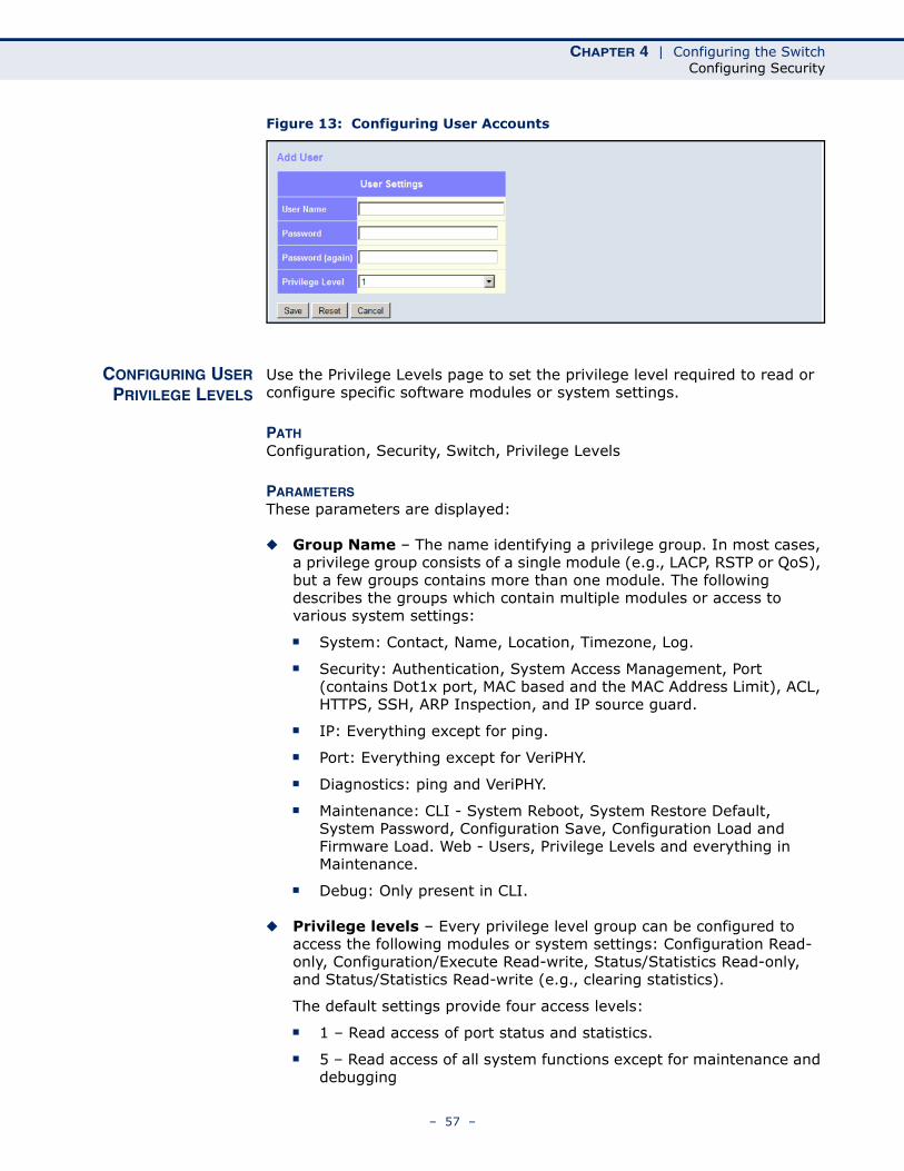
CHAPTER 4 | Configuring the SwitchConfiguring Security
Figure 13: Configuring User Accounts
CONFIGURING USERPRIVILEGE LEVELS
Use the Privilege Levels page to set the privilege level required to read or configure specific software modules or system settings.
PATH Configuration, Security, Switch, Privilege Levels
PARAMETERSThese parameters are displayed:
◆ Group Name – The name identifying a privilege group. In most cases, a privilege group consists of a single module (e.g., LACP, RSTP or QoS), but a few groups contains more than one module. The following describes the groups which contain multiple modules or access to various system settings:
■ System: Contact, Name, Location, Timezone, Log.
■ Security: Authentication, System Access Management, Port (contains Dot1x port, MAC based and the MAC Address Limit), ACL, HTTPS, SSH, ARP Inspection, and IP source guard.
■ IP: Everything except for ping.
■ Port: Everything except for VeriPHY.
■ Diagnostics: ping and VeriPHY.
■ Maintenance: CLI - System Reboot, System Restore Default, System Password, Configuration Save, Configuration Load and Firmware Load. Web - Users, Privilege Levels and everything in Maintenance.
■ Debug: Only present in CLI.
◆ Privilege levels – Every privilege level group can be configured to access the following modules or system settings: Configuration Read-only, Configuration/Execute Read-write, Status/Statistics Read-only, and Status/Statistics Read-write (e.g., clearing statistics).
The default settings provide four access levels:
■ 1 – Read access of port status and statistics.
■ 5 – Read access of all system functions except for maintenance and debugging
– 57 –
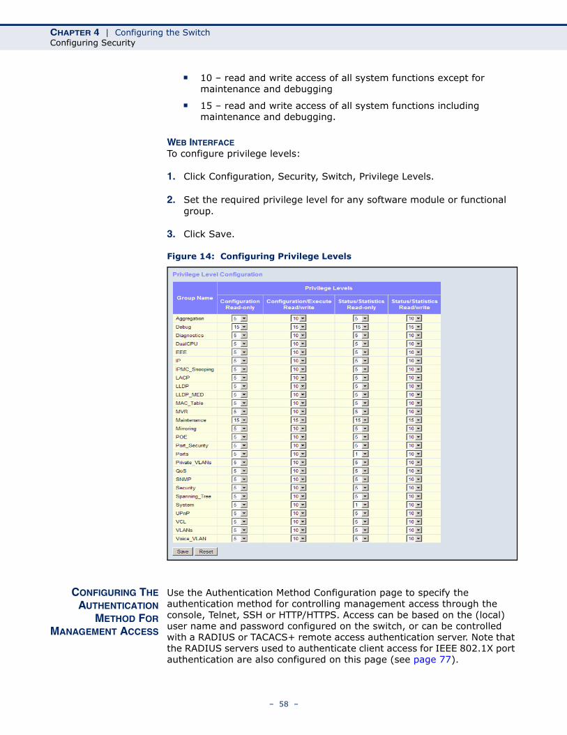
CHAPTER 4 | Configuring the SwitchConfiguring Security
■ 10 – read and write access of all system functions except for maintenance and debugging
■ 15 – read and write access of all system functions including maintenance and debugging.
WEB INTERFACETo configure privilege levels:
1. Click Configuration, Security, Switch, Privilege Levels.
2. Set the required privilege level for any software module or functional group.
3. Click Save.
Figure 14: Configuring Privilege Levels
CONFIGURING THEAUTHENTICATION
METHOD FORMANAGEMENT ACCESS
Use the Authentication Method Configuration page to specify the authentication method for controlling management access through the console, Telnet, SSH or HTTP/HTTPS. Access can be based on the (local) user name and password configured on the switch, or can be controlled with a RADIUS or TACACS+ remote access authentication server. Note that the RADIUS servers used to authenticate client access for IEEE 802.1X port authentication are also configured on this page (see page 77).
– 58 –
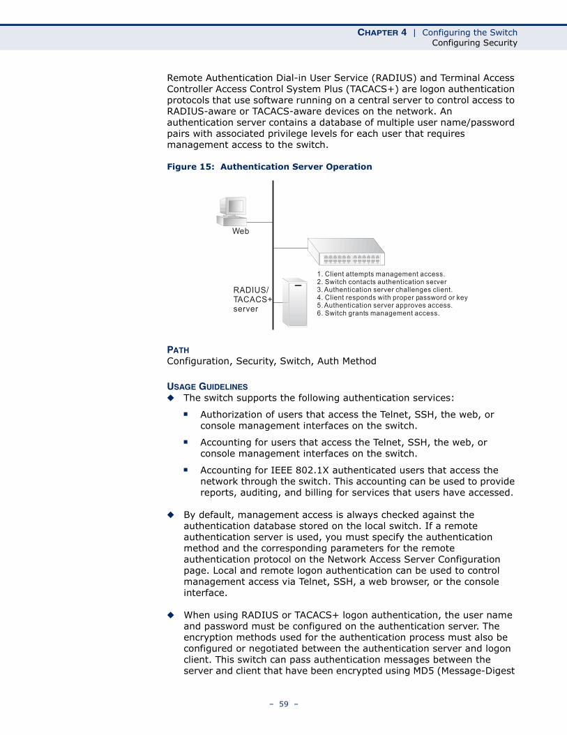
CHAPTER 4 | Configuring the SwitchConfiguring Security
Remote Authentication Dial-in User Service (RADIUS) and Terminal Access Controller Access Control System Plus (TACACS+) are logon authentication protocols that use software running on a central server to control access to RADIUS-aware or TACACS-aware devices on the network. An authentication server contains a database of multiple user name/password pairs with associated privilege levels for each user that requires management access to the switch.
Figure 15: Authentication Server Operation
PATH Configuration, Security, Switch, Auth Method
USAGE GUIDELINES◆ The switch supports the following authentication services:
■ Authorization of users that access the Telnet, SSH, the web, or console management interfaces on the switch.
■ Accounting for users that access the Telnet, SSH, the web, or console management interfaces on the switch.
■ Accounting for IEEE 802.1X authenticated users that access the network through the switch. This accounting can be used to provide reports, auditing, and billing for services that users have accessed.
◆ By default, management access is always checked against the authentication database stored on the local switch. If a remote authentication server is used, you must specify the authentication method and the corresponding parameters for the remote authentication protocol on the Network Access Server Configuration page. Local and remote logon authentication can be used to control management access via Telnet, SSH, a web browser, or the console interface.
◆ When using RADIUS or TACACS+ logon authentication, the user name and password must be configured on the authentication server. The encryption methods used for the authentication process must also be configured or negotiated between the authentication server and logon client. This switch can pass authentication messages between the server and client that have been encrypted using MD5 (Message-Digest
Web
RADIUS/TACACS+server
1. Client attempts management access.2. Switch contacts authentication server.3. Authentication server challenges client.4. Client responds with proper password or key.5. Authentication server approves access.6. Switch grants management access.
– 59 –
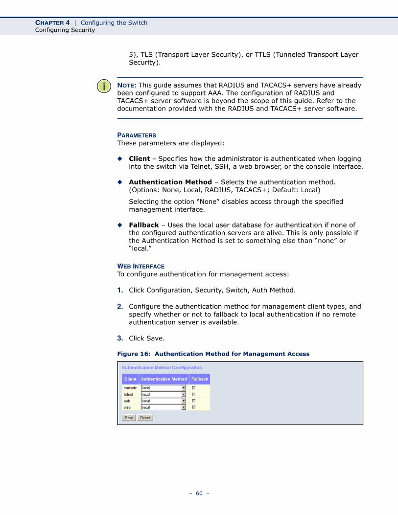
CHAPTER 4 | Configuring the SwitchConfiguring Security
5), TLS (Transport Layer Security), or TTLS (Tunneled Transport Layer Security).
NOTE: This guide assumes that RADIUS and TACACS+ servers have already been configured to support AAA. The configuration of RADIUS and TACACS+ server software is beyond the scope of this guide. Refer to the documentation provided with the RADIUS and TACACS+ server software.
PARAMETERSThese parameters are displayed:
◆ Client – Specifies how the administrator is authenticated when logging into the switch via Telnet, SSH, a web browser, or the console interface.
◆ Authentication Method – Selects the authentication method. (Options: None, Local, RADIUS, TACACS+; Default: Local)
Selecting the option “None” disables access through the specified management interface.
◆ Fallback – Uses the local user database for authentication if none of the configured authentication servers are alive. This is only possible if the Authentication Method is set to something else than “none” or “local.”
WEB INTERFACETo configure authentication for management access:
1. Click Configuration, Security, Switch, Auth Method.
2. Configure the authentication method for management client types, and specify whether or not to fallback to local authentication if no remote authentication server is available.
3. Click Save.
Figure 16: Authentication Method for Management Access
– 60 –
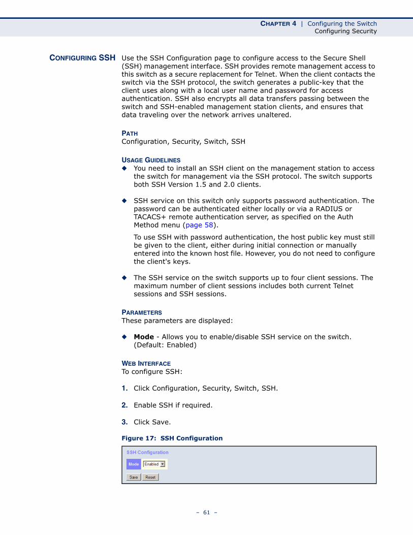
CHAPTER 4 | Configuring the SwitchConfiguring Security
CONFIGURING SSH Use the SSH Configuration page to configure access to the Secure Shell (SSH) management interface. SSH provides remote management access to this switch as a secure replacement for Telnet. When the client contacts the switch via the SSH protocol, the switch generates a public-key that the client uses along with a local user name and password for access authentication. SSH also encrypts all data transfers passing between the switch and SSH-enabled management station clients, and ensures that data traveling over the network arrives unaltered.
PATH Configuration, Security, Switch, SSH
USAGE GUIDELINES◆ You need to install an SSH client on the management station to access
the switch for management via the SSH protocol. The switch supports both SSH Version 1.5 and 2.0 clients.
◆ SSH service on this switch only supports password authentication. The password can be authenticated either locally or via a RADIUS or TACACS+ remote authentication server, as specified on the Auth Method menu (page 58).
To use SSH with password authentication, the host public key must still be given to the client, either during initial connection or manually entered into the known host file. However, you do not need to configure the client's keys.
◆ The SSH service on the switch supports up to four client sessions. The maximum number of client sessions includes both current Telnet sessions and SSH sessions.
PARAMETERSThese parameters are displayed:
◆ Mode - Allows you to enable/disable SSH service on the switch. (Default: Enabled)
WEB INTERFACETo configure SSH:
1. Click Configuration, Security, Switch, SSH.
2. Enable SSH if required.
3. Click Save.
Figure 17: SSH Configuration
– 61 –
CHAPTER 4 | Configuring the SwitchConfiguring Security
CONFIGURING HTTPS Use the HTTPS Configuration page to enable the Secure Hypertext Transfer Protocol (HTTPS) over the Secure Socket Layer (SSL). HTTPS provides secure access (i.e., an encrypted connection) to the switch's web interface.
PATH Configuration, Security, Switch, HTTPS
USAGE GUIDELINES◆ If you enable HTTPS, you must indicate this in the URL that you specify
in your browser: https://device[:port-number]
◆ When you start HTTPS, the connection is established in this way:
■ The client authenticates the server using the server's digital certificate.
■ The client and server negotiate a set of security protocols to use for the connection.
■ The client and server generate session keys for encrypting and decrypting data.
■ The client and server establish a secure encrypted connection.
A padlock icon should appear in the status bar for Internet Explorer 5.x or above, Netscape 6.2 or above, and Mozilla Firefox 2.0.0.0 or above.
◆ The following web browsers and operating systems currently support HTTPS:
PARAMETERSThese parameters are displayed:
◆ Mode - Enables HTTPS service on the switch. (Default: Enabled)
◆ Automatic Redirect - Sets the HTTPS redirect mode operation. When enabled, management access to the HTTP web interface for the switch are automatically redirected to HTTPS. (Default: Disabled)
WEB INTERFACETo configure HTTPS:
1. Click Configuration, HTTPS.
2. Enable HTTPS if required and set the Automatic Redirect mode.
Table 5: HTTPS System Support
Web Browser Operating System
Internet Explorer 5.0 or later Windows 98,Windows NT (with service pack 6a), Windows 2000, Windows XP, Windows Vista, Windows 7
Netscape 6.2 or later Windows 98,Windows NT (with service pack 6a), Windows 2000, Windows XP, Windows Vista, Solaris 2.6
Mozilla Firefox 2.0.0.0 or later Windows 2000, Windows XP, Windows Vista, Linux
– 62 –
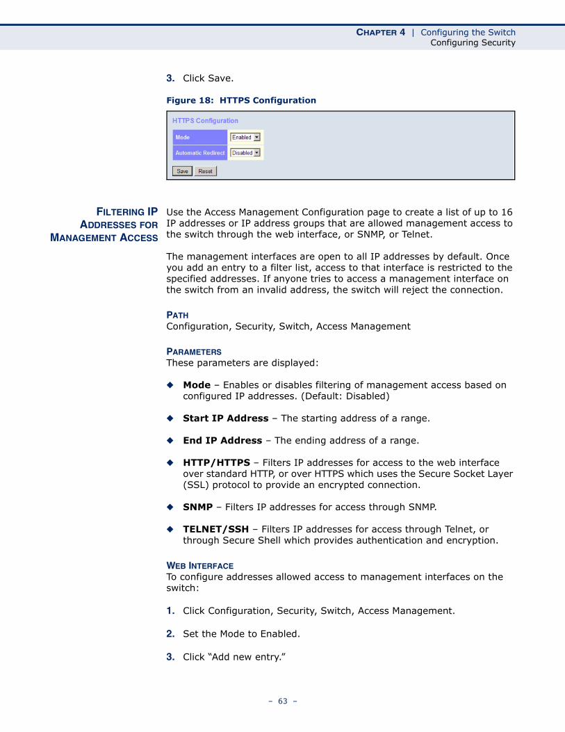
CHAPTER 4 | Configuring the SwitchConfiguring Security
3. Click Save.
Figure 18: HTTPS Configuration
FILTERING IPADDRESSES FOR
MANAGEMENT ACCESS
Use the Access Management Configuration page to create a list of up to 16 IP addresses or IP address groups that are allowed management access to the switch through the web interface, or SNMP, or Telnet.
The management interfaces are open to all IP addresses by default. Once you add an entry to a filter list, access to that interface is restricted to the specified addresses. If anyone tries to access a management interface on the switch from an invalid address, the switch will reject the connection.
PATH Configuration, Security, Switch, Access Management
PARAMETERSThese parameters are displayed:
◆ Mode – Enables or disables filtering of management access based on configured IP addresses. (Default: Disabled)
◆ Start IP Address – The starting address of a range.
◆ End IP Address – The ending address of a range.
◆ HTTP/HTTPS – Filters IP addresses for access to the web interface over standard HTTP, or over HTTPS which uses the Secure Socket Layer (SSL) protocol to provide an encrypted connection.
◆ SNMP – Filters IP addresses for access through SNMP.
◆ TELNET/SSH – Filters IP addresses for access through Telnet, or through Secure Shell which provides authentication and encryption.
WEB INTERFACETo configure addresses allowed access to management interfaces on the switch:
1. Click Configuration, Security, Switch, Access Management.
2. Set the Mode to Enabled.
3. Click “Add new entry.”
– 63 –
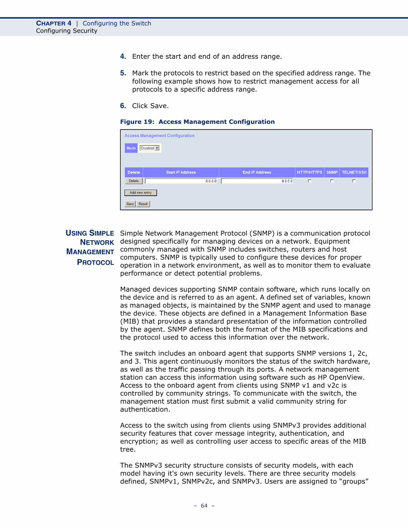
CHAPTER 4 | Configuring the SwitchConfiguring Security
4. Enter the start and end of an address range.
5. Mark the protocols to restrict based on the specified address range. The following example shows how to restrict management access for all protocols to a specific address range.
6. Click Save.
Figure 19: Access Management Configuration
USING SIMPLENETWORK
MANAGEMENT
PROTOCOL
Simple Network Management Protocol (SNMP) is a communication protocol designed specifically for managing devices on a network. Equipment commonly managed with SNMP includes switches, routers and host computers. SNMP is typically used to configure these devices for proper operation in a network environment, as well as to monitor them to evaluate performance or detect potential problems.
Managed devices supporting SNMP contain software, which runs locally on the device and is referred to as an agent. A defined set of variables, known as managed objects, is maintained by the SNMP agent and used to manage the device. These objects are defined in a Management Information Base (MIB) that provides a standard presentation of the information controlled by the agent. SNMP defines both the format of the MIB specifications and the protocol used to access this information over the network.
The switch includes an onboard agent that supports SNMP versions 1, 2c, and 3. This agent continuously monitors the status of the switch hardware, as well as the traffic passing through its ports. A network management station can access this information using software such as HP OpenView. Access to the onboard agent from clients using SNMP v1 and v2c is controlled by community strings. To communicate with the switch, the management station must first submit a valid community string for authentication.
Access to the switch using from clients using SNMPv3 provides additional security features that cover message integrity, authentication, and encryption; as well as controlling user access to specific areas of the MIB tree.
The SNMPv3 security structure consists of security models, with each model having it's own security levels. There are three security models defined, SNMPv1, SNMPv2c, and SNMPv3. Users are assigned to “groups”
– 64 –
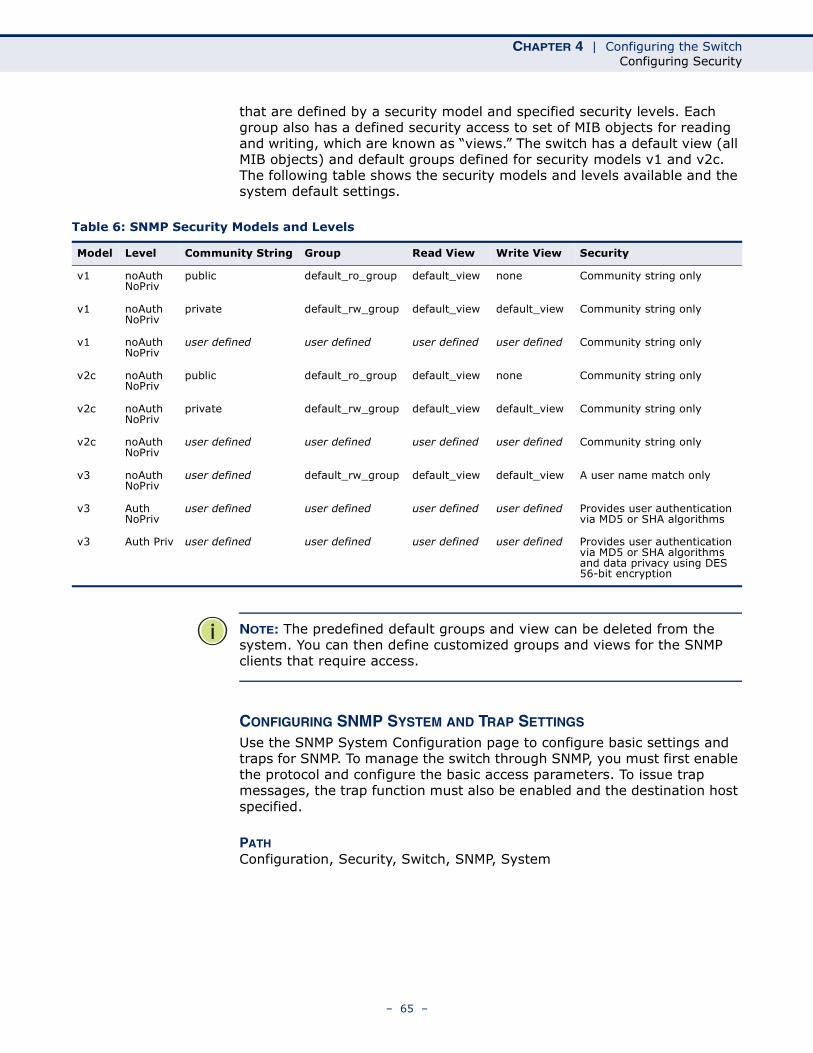
CHAPTER 4 | Configuring the SwitchConfiguring Security
that are defined by a security model and specified security levels. Each group also has a defined security access to set of MIB objects for reading and writing, which are known as “views.” The switch has a default view (all MIB objects) and default groups defined for security models v1 and v2c. The following table shows the security models and levels available and the system default settings.
NOTE: The predefined default groups and view can be deleted from the system. You can then define customized groups and views for the SNMP clients that require access.
CONFIGURING SNMP SYSTEM AND TRAP SETTINGS
Use the SNMP System Configuration page to configure basic settings and traps for SNMP. To manage the switch through SNMP, you must first enable the protocol and configure the basic access parameters. To issue trap messages, the trap function must also be enabled and the destination host specified.
PATH Configuration, Security, Switch, SNMP, System
Table 6: SNMP Security Models and Levels
Model Level Community String Group Read View Write View Security
v1 noAuth NoPriv
public default_ro_group default_view none Community string only
v1 noAuth NoPriv
private default_rw_group default_view default_view Community string only
v1 noAuth NoPriv
user defined user defined user defined user defined Community string only
v2c noAuth NoPriv
public default_ro_group default_view none Community string only
v2c noAuth NoPriv
private default_rw_group default_view default_view Community string only
v2c noAuth NoPriv
user defined user defined user defined user defined Community string only
v3 noAuth NoPriv
user defined default_rw_group default_view default_view A user name match only
v3 Auth NoPriv
user defined user defined user defined user defined Provides user authentication via MD5 or SHA algorithms
v3 Auth Priv user defined user defined user defined user defined Provides user authentication via MD5 or SHA algorithms and data privacy using DES 56-bit encryption
– 65 –
CHAPTER 4 | Configuring the SwitchConfiguring Security
PARAMETERSThese parameters are displayed:
SNMP System Configuration
◆ Mode - Enables or disables SNMP service. (Default: Disabled)
◆ Version - Specifies the SNMP version to use. (Options: SNMP v1, SNMP v2c, SNMP v3; Default: SNMP v2c)
◆ Read Community - The community used for read-only access to the SNMP agent. (Range: 0-255 characters, ASCII characters 33-126 only; Default: public)
This parameter only applies to SNMPv1 and SNMPv2c. SNMPv3 uses the User-based Security Model (USM) for authentication and privacy. This community string is associated with SNMPv1 or SNMPv2 clients in the SNMPv3 Communities table (page 69).
◆ Write Community - The community used for read/write access to the SNMP agent. (Range: 0-255 characters, ASCII characters 33-126 only; Default: private)
This parameter only applies to SNMPv1 and SNMPv2c. SNMPv3 uses the User-based Security Model (USM) for authentication and privacy. This community string is associated with SNMPv1 or SNMPv2 clients in the SNMPv3 Communities table (page 69).
◆ Engine ID - The SNMPv3 engine ID. (Range: 10-64 hex digits, excluding a string of all 0’s or all F’s; Default: 800007e5017f000001)
An SNMPv3 engine is an independent SNMP agent that resides on the switch. This engine protects against message replay, delay, and redirection. The engine ID is also used in combination with user passwords to generate the security keys for authenticating and encrypting SNMPv3 packets.
A local engine ID is automatically generated that is unique to the switch. This is referred to as the default engine ID. If the local engine ID is deleted or changed, all local SNMP users will be cleared. You will need to reconfigure all existing users.
SNMP Trap Configuration
◆ Trap Mode - Enables or disables SNMP traps. (Default: Disabled)
You should enable SNMP traps so that key events are reported by this switch to your management station. Traps indicating status changes can be issued by the switch to the specified trap manager by sending authentication failure messages and other trap messages.
◆ Trap Version - Indicates if the target user is running SNMP v1, v2c, or v3. (Default: SNMP v1)
◆ Trap Community - Specifies the community access string to use when sending SNMP trap packets. (Range: 0-255 characters, ASCII characters 33-126 only; Default: public)
– 66 –
CHAPTER 4 | Configuring the SwitchConfiguring Security
◆ Trap Destination Address - IPv4 address of the management station to receive notification messages.
◆ Trap Destination IPv6 Address - IPv6 address of the management station to receive notification messages. An IPv6 address must be formatted according to RFC 2373 “IPv6 Addressing Architecture,” using 8 colon-separated 16-bit hexadecimal values. One double colon may be used to indicate the appropriate number of zeros required to fill the undefined fields.
◆ Trap Authentication Failure - Issues a notification message to specified IP trap managers whenever authentication of an SNMP request fails. (Default: Enabled)
◆ Trap Link-up and Link-down - Issues a notification message whenever a port link is established or broken. (Default: Enabled)
◆ Trap Inform Mode - Enables or disables sending notifications as inform messages. Note that this option is only available for version 2c and 3 hosts. (Default: traps are used)
The recipient of a trap message does not send a response to the switch. Traps are therefore not as reliable as inform messages, which include a request for acknowledgement of receipt. Informs can be used to ensure that critical information is received by the host. However, note that informs consume more system resources because they must be kept in memory until a response is received. Informs also add to network traffic. You should consider these effects when deciding whether to issue notifications as traps or informs.
◆ Trap Inform Timeout - The number of seconds to wait for an acknowledgment before resending an inform message. (Range: 0-2147 seconds; Default: 1 second)
◆ Trap Inform Retry Times - The maximum number of times to resend an inform message if the recipient does not acknowledge receipt. (Range: 0-255; Default: 5)
◆ Trap Probe Security Engine ID (SNMPv3) - Specifies whether or not to use the engine ID of the SNMP trap probe in trap and inform messages. (Default: Enabled)
◆ Trap Security Engine ID (SNMPv3) - Indicates the SNMP trap security engine ID. SNMPv3 sends traps and informs using USM for authentication and privacy. A unique engine ID for these traps and informs is needed. When “Trap Probe Security Engine ID” is enabled, the ID will be probed automatically. Otherwise, the ID specified in this field is used. (Range: 10-64 hex digits, excluding a string of all 0’s or all F’s)
NOTE: The Trap Probe Security Engine ID must be disabled before an engine ID can be manually entered in this field.
– 67 –
CHAPTER 4 | Configuring the SwitchConfiguring Security
◆ Trap Security Name (SNMPv3) - Indicates the SNMP trap security name. SNMPv3 traps and informs use USM for authentication and privacy. A unique security name is needed when SNMPv3 traps or informs are enabled.
NOTE: To select a name from this field, first enter an SNMPv3 user with the same Trap Security Engine ID in the SNMPv3 Users Configuration menu (see "Configuring SNMPv3 Users" on page 70).
WEB INTERFACETo configure SNMP system and trap settings:
1. Click Configuration, Security, Switch, SNMP, System.
2. In the SNMP System Configuration table, set the Mode to Enabled to enable SNMP service on the switch, specify the SNMP version to use, change the community access strings if required, and set the engine ID if SNMP version 3 is used.
3. In the SNMP Trap Configuration table, enable the Trap Mode to allow the switch to send SNMP traps. Specify the trap version, trap community, and IP address of the management station that will receive trap messages either as an IPv4 or IPv6 address. Select the trap types to issue, and set the trap inform settings for SNMP v2c or v3 clients. For SNMP v3 clients, configure the security engine ID and security name used in v3 trap and inform messages.
4. Click Save.
– 68 –
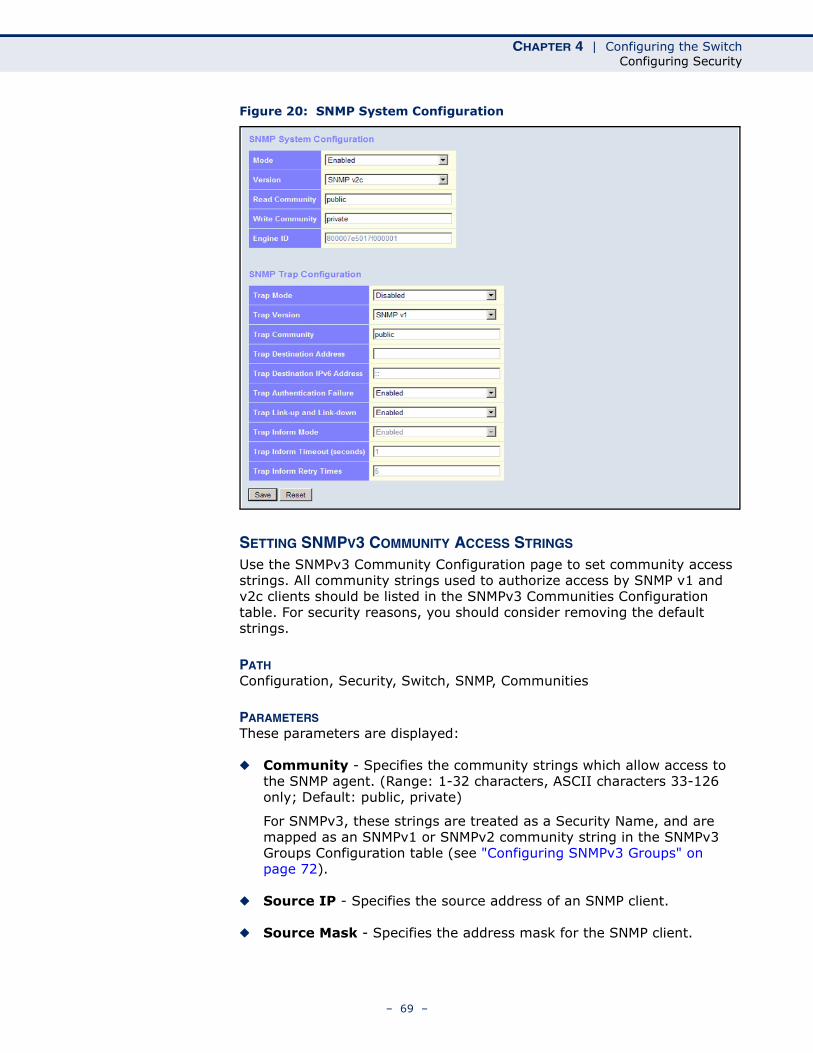
CHAPTER 4 | Configuring the SwitchConfiguring Security
Figure 20: SNMP System Configuration
SETTING SNMPV3 COMMUNITY ACCESS STRINGS
Use the SNMPv3 Community Configuration page to set community access strings. All community strings used to authorize access by SNMP v1 and v2c clients should be listed in the SNMPv3 Communities Configuration table. For security reasons, you should consider removing the default strings.
PATH Configuration, Security, Switch, SNMP, Communities
PARAMETERSThese parameters are displayed:
◆ Community - Specifies the community strings which allow access to the SNMP agent. (Range: 1-32 characters, ASCII characters 33-126 only; Default: public, private)
For SNMPv3, these strings are treated as a Security Name, and are mapped as an SNMPv1 or SNMPv2 community string in the SNMPv3 Groups Configuration table (see "Configuring SNMPv3 Groups" on page 72).
◆ Source IP - Specifies the source address of an SNMP client.
◆ Source Mask - Specifies the address mask for the SNMP client.
– 69 –
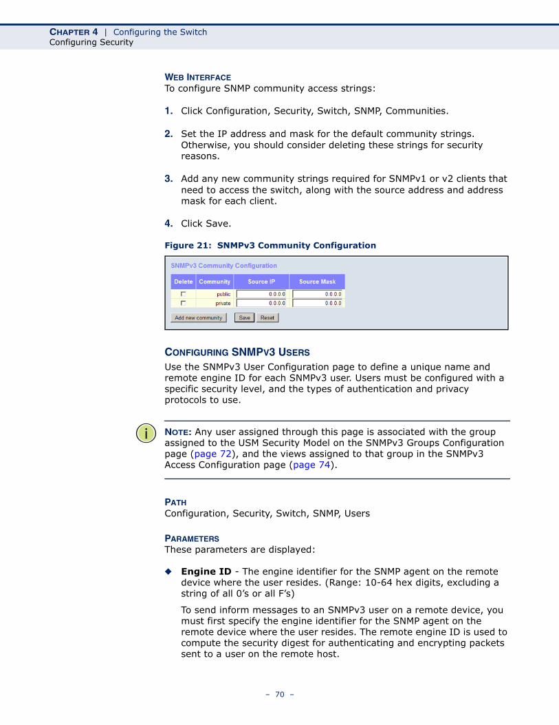
CHAPTER 4 | Configuring the SwitchConfiguring Security
WEB INTERFACETo configure SNMP community access strings:
1. Click Configuration, Security, Switch, SNMP, Communities.
2. Set the IP address and mask for the default community strings. Otherwise, you should consider deleting these strings for security reasons.
3. Add any new community strings required for SNMPv1 or v2 clients that need to access the switch, along with the source address and address mask for each client.
4. Click Save.
Figure 21: SNMPv3 Community Configuration
CONFIGURING SNMPV3 USERS
Use the SNMPv3 User Configuration page to define a unique name and remote engine ID for each SNMPv3 user. Users must be configured with a specific security level, and the types of authentication and privacy protocols to use.
NOTE: Any user assigned through this page is associated with the group assigned to the USM Security Model on the SNMPv3 Groups Configuration page (page 72), and the views assigned to that group in the SNMPv3 Access Configuration page (page 74).
PATH Configuration, Security, Switch, SNMP, Users
PARAMETERSThese parameters are displayed:
◆ Engine ID - The engine identifier for the SNMP agent on the remote device where the user resides. (Range: 10-64 hex digits, excluding a string of all 0’s or all F’s)
To send inform messages to an SNMPv3 user on a remote device, you must first specify the engine identifier for the SNMP agent on the remote device where the user resides. The remote engine ID is used to compute the security digest for authenticating and encrypting packets sent to a user on the remote host.
– 70 –
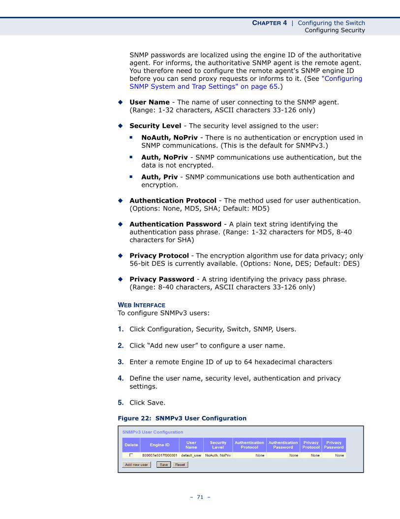
CHAPTER 4 | Configuring the SwitchConfiguring Security
SNMP passwords are localized using the engine ID of the authoritative agent. For informs, the authoritative SNMP agent is the remote agent. You therefore need to configure the remote agent's SNMP engine ID before you can send proxy requests or informs to it. (See "Configuring SNMP System and Trap Settings" on page 65.)
◆ User Name - The name of user connecting to the SNMP agent. (Range: 1-32 characters, ASCII characters 33-126 only)
◆ Security Level - The security level assigned to the user:
■ NoAuth, NoPriv - There is no authentication or encryption used in SNMP communications. (This is the default for SNMPv3.)
■ Auth, NoPriv - SNMP communications use authentication, but the data is not encrypted.
■ Auth, Priv - SNMP communications use both authentication and encryption.
◆ Authentication Protocol - The method used for user authentication. (Options: None, MD5, SHA; Default: MD5)
◆ Authentication Password - A plain text string identifying the authentication pass phrase. (Range: 1-32 characters for MD5, 8-40 characters for SHA)
◆ Privacy Protocol - The encryption algorithm use for data privacy; only 56-bit DES is currently available. (Options: None, DES; Default: DES)
◆ Privacy Password - A string identifying the privacy pass phrase. (Range: 8-40 characters, ASCII characters 33-126 only)
WEB INTERFACETo configure SNMPv3 users:
1. Click Configuration, Security, Switch, SNMP, Users.
2. Click “Add new user” to configure a user name.
3. Enter a remote Engine ID of up to 64 hexadecimal characters
4. Define the user name, security level, authentication and privacy settings.
5. Click Save.
Figure 22: SNMPv3 User Configuration
– 71 –
CHAPTER 4 | Configuring the SwitchConfiguring Security
CONFIGURING SNMPV3 GROUPS
Use the SNMPv3 Group Configuration page to configure SNMPv3 groups. An SNMPv3 group defines the access policy for assigned users, restricting them to specific read and write views as defined on the SNMPv3 Access Configuration page (page 74). You can use the pre-defined default groups, or create a new group and the views authorized for that group.
PATH Configuration, Security, Switch, SNMP, Groups
PARAMETERSThese parameters are displayed:
◆ Security Model - The user security model. (Options: SNMP v1, v2c, or the User-based Security Model – usm).
◆ Security Name - The name of a user connecting to the SNMP agent. (Range: 1-32 characters, ASCII characters 33-126 only)
The options displayed for this parameter depend on the selected Security Model. For SNMP v1 and v2c, the switch displays the names configured on the SNMPv3 Communities Configuration menu (see page 69). For USM (or SNMPv3), the switch displays the names configured with the local engine ID in the SNMPv3 Users Configuration menu (see page 70). To modify an entry for USM, the current entry must first be deleted.
◆ Group Name - The name of the SNMP group. (Range: 1-32 characters, ASCII characters 33-126 only)
WEB INTERFACETo configure SNMPv3 groups:
1. Click Configuration, Security, Switch, SNMP, Groups.
2. Click “Add new group” to set up a new group.
3. Select a security model.
4. Select the security name. For SNMP v1 and v2c, the security names displayed are based on the those configured in the SNMPv3 Communities menu. For USM, the security names displayed are based on the those configured in the SNMPv3 Users Configuration menu.
5. Enter a group name. Note that the views assigned to a group must be specified on the SNMP Accesses Configuration menu (see page 74).
6. Click Save.
– 72 –
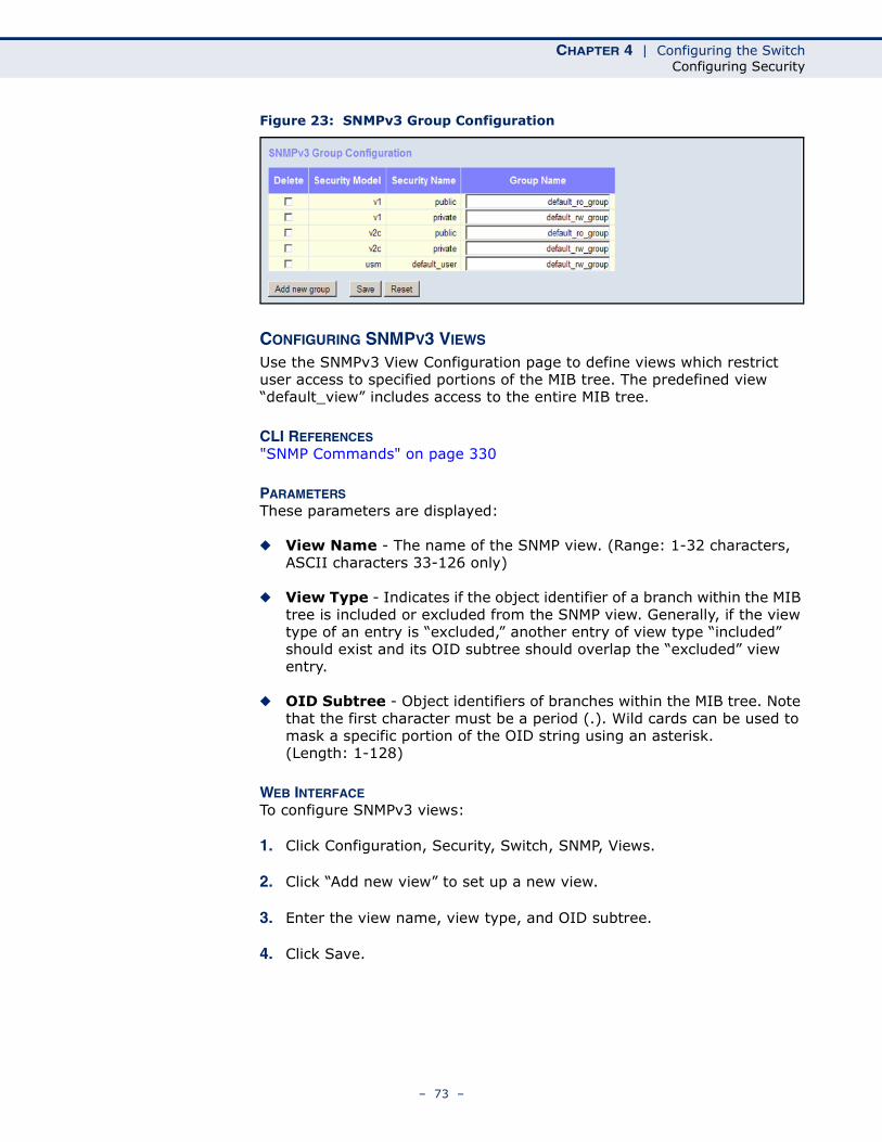
CHAPTER 4 | Configuring the SwitchConfiguring Security
Figure 23: SNMPv3 Group Configuration
CONFIGURING SNMPV3 VIEWS
Use the SNMPv3 View Configuration page to define views which restrict user access to specified portions of the MIB tree. The predefined view “default_view” includes access to the entire MIB tree.
CLI REFERENCES"SNMP Commands" on page 330
PARAMETERSThese parameters are displayed:
◆ View Name - The name of the SNMP view. (Range: 1-32 characters, ASCII characters 33-126 only)
◆ View Type - Indicates if the object identifier of a branch within the MIB tree is included or excluded from the SNMP view. Generally, if the view type of an entry is “excluded,” another entry of view type “included” should exist and its OID subtree should overlap the “excluded” view entry.
◆ OID Subtree - Object identifiers of branches within the MIB tree. Note that the first character must be a period (.). Wild cards can be used to mask a specific portion of the OID string using an asterisk. (Length: 1-128)
WEB INTERFACETo configure SNMPv3 views:
1. Click Configuration, Security, Switch, SNMP, Views.
2. Click “Add new view” to set up a new view.
3. Enter the view name, view type, and OID subtree.
4. Click Save.
– 73 –
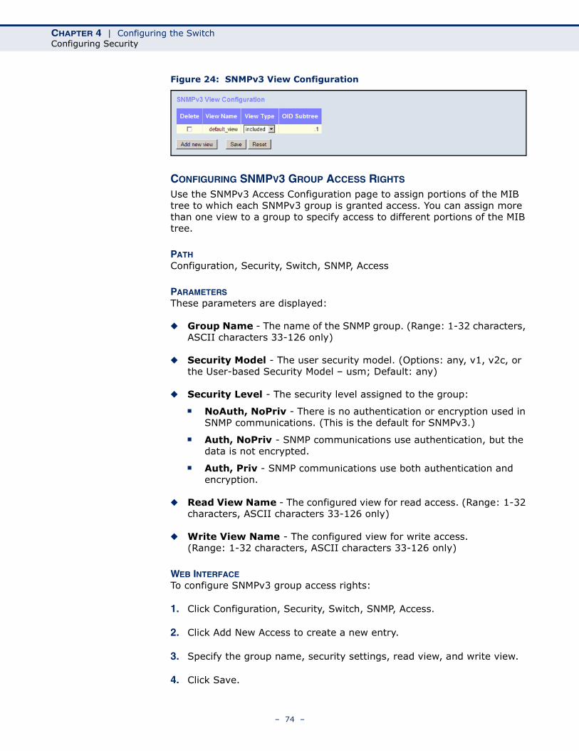
CHAPTER 4 | Configuring the SwitchConfiguring Security
Figure 24: SNMPv3 View Configuration
CONFIGURING SNMPV3 GROUP ACCESS RIGHTS
Use the SNMPv3 Access Configuration page to assign portions of the MIB tree to which each SNMPv3 group is granted access. You can assign more than one view to a group to specify access to different portions of the MIB tree.
PATH Configuration, Security, Switch, SNMP, Access
PARAMETERSThese parameters are displayed:
◆ Group Name - The name of the SNMP group. (Range: 1-32 characters, ASCII characters 33-126 only)
◆ Security Model - The user security model. (Options: any, v1, v2c, or the User-based Security Model – usm; Default: any)
◆ Security Level - The security level assigned to the group:
■ NoAuth, NoPriv - There is no authentication or encryption used in SNMP communications. (This is the default for SNMPv3.)
■ Auth, NoPriv - SNMP communications use authentication, but the data is not encrypted.
■ Auth, Priv - SNMP communications use both authentication and encryption.
◆ Read View Name - The configured view for read access. (Range: 1-32 characters, ASCII characters 33-126 only)
◆ Write View Name - The configured view for write access. (Range: 1-32 characters, ASCII characters 33-126 only)
WEB INTERFACETo configure SNMPv3 group access rights:
1. Click Configuration, Security, Switch, SNMP, Access.
2. Click Add New Access to create a new entry.
3. Specify the group name, security settings, read view, and write view.
4. Click Save.
– 74 –
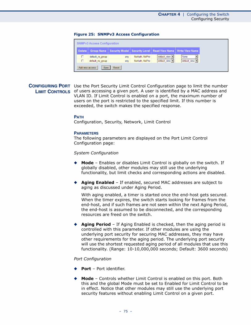
CHAPTER 4 | Configuring the SwitchConfiguring Security
Figure 25: SNMPv3 Access Configuration
CONFIGURING PORTLIMIT CONTROLS
Use the Port Security Limit Control Configuration page to limit the number of users accessing a given port. A user is identified by a MAC address and VLAN ID. If Limit Control is enabled on a port, the maximum number of users on the port is restricted to the specified limit. If this number is exceeded, the switch makes the specified response.
PATH Configuration, Security, Network, Limit Control
PARAMETERSThe following parameters are displayed on the Port Limit Control Configuration page:
System Configuration
◆ Mode – Enables or disables Limit Control is globally on the switch. If globally disabled, other modules may still use the underlying functionality, but limit checks and corresponding actions are disabled.
◆ Aging Enabled – If enabled, secured MAC addresses are subject to aging as discussed under Aging Period.
With aging enabled, a timer is started once the end-host gets secured. When the timer expires, the switch starts looking for frames from the end-host, and if such frames are not seen within the next Aging Period, the end-host is assumed to be disconnected, and the corresponding resources are freed on the switch.
◆ Aging Period – If Aging Enabled is checked, then the aging period is controlled with this parameter. If other modules are using the underlying port security for securing MAC addresses, they may have other requirements for the aging period. The underlying port security will use the shortest requested aging period of all modules that use this functionality. (Range: 10-10,000,000 seconds; Default: 3600 seconds)
Port Configuration
◆ Port – Port identifier.
◆ Mode – Controls whether Limit Control is enabled on this port. Both this and the global Mode must be set to Enabled for Limit Control to be in effect. Notice that other modules may still use the underlying port security features without enabling Limit Control on a given port.
– 75 –
CHAPTER 4 | Configuring the SwitchConfiguring Security
◆ Limit – The maximum number of MAC addresses that can be secured on this port. This number cannot exceed 1024. If the limit is exceeded, the corresponding action is taken.
The switch is “initialized” with a total number of MAC addresses from which all ports draw whenever a new MAC address is seen on a Port Security-enabled port. Since all ports draw from the same pool, it may happen that a configured maximum cannot be granted if the remaining ports have already used all available MAC addresses.
◆ Action – If Limit is reached, the switch can take one of the following actions:
■ None: Do not allow more than the specified Limit of MAC addresses on the port, but take no further action.
■ Trap: If Limit + 1 MAC addresses is seen on the port, send an SNMP trap. If Aging is disabled, only one SNMP trap will be sent, but with Aging enabled, new SNMP traps will be sent every time the limit is exceeded.
■ Shutdown: If Limit + 1 MAC addresses is seen on the port, shut down the port. This implies that all secured MAC addresses will be removed from the port, and no new addresses will be learned. Even if the link is physically disconnected and reconnected on the port (by disconnecting the cable), the port will remain shut down. There are three ways to re-open the port:
■ Boot the switch,
■ Disable and re-enable Limit Control on the port or the switch,
■ Click the Reopen button.
■ Trap & Shutdown: If Limit + 1 MAC addresses is seen on the port, both the “Trap” and the “Shutdown” actions described above will be taken.
◆ State – This column shows the current state of the port as seen from the Limit Control's point of view. The state takes one of four values:
■ Disabled: Limit Control is either globally disabled or disabled on the port.
■ Ready: The limit is not yet reached. This can be shown for all Actions.
■ Limit Reached: Indicates that the limit is reached on this port. This state can only be shown if Action is set to None or Trap.
■ Shutdown: Indicates that the port is shut down by the Limit Control module. This state can only be shown if Action is set to Shutdown or Trap & Shutdown.
◆ Re-open – If a port is shut down by this module, you may reopen it by clicking this button, which will only be enabled if this is the case. For other methods, refer to Shutdown in the Action section.
Note, that clicking the Reopen button causes the page to be refreshed, so non-committed changes will be lost.
– 76 –
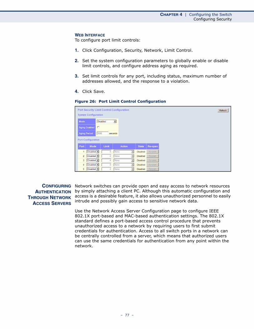
CHAPTER 4 | Configuring the SwitchConfiguring Security
WEB INTERFACETo configure port limit controls:
1. Click Configuration, Security, Network, Limit Control.
2. Set the system configuration parameters to globally enable or disable limit controls, and configure address aging as required.
3. Set limit controls for any port, including status, maximum number of addresses allowed, and the response to a violation.
4. Click Save.
Figure 26: Port Limit Control Configuration
CONFIGURINGAUTHENTICATION
THROUGH NETWORKACCESS SERVERS
Network switches can provide open and easy access to network resources by simply attaching a client PC. Although this automatic configuration and access is a desirable feature, it also allows unauthorized personnel to easily intrude and possibly gain access to sensitive network data.
Use the Network Access Server Configuration page to configure IEEE 802.1X port-based and MAC-based authentication settings. The 802.1X standard defines a port-based access control procedure that prevents unauthorized access to a network by requiring users to first submit credentials for authentication. Access to all switch ports in a network can be centrally controlled from a server, which means that authorized users can use the same credentials for authentication from any point within the network.
– 77 –
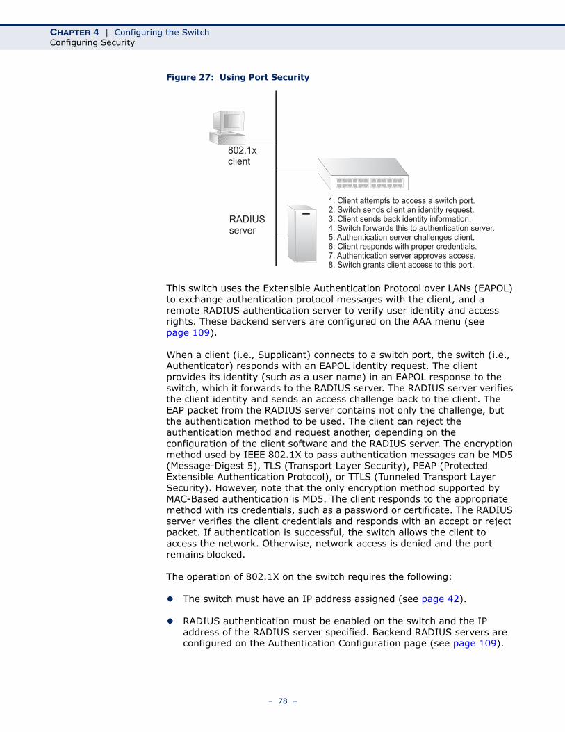
CHAPTER 4 | Configuring the SwitchConfiguring Security
Figure 27: Using Port Security
This switch uses the Extensible Authentication Protocol over LANs (EAPOL) to exchange authentication protocol messages with the client, and a remote RADIUS authentication server to verify user identity and access rights. These backend servers are configured on the AAA menu (see page 109).
When a client (i.e., Supplicant) connects to a switch port, the switch (i.e., Authenticator) responds with an EAPOL identity request. The client provides its identity (such as a user name) in an EAPOL response to the switch, which it forwards to the RADIUS server. The RADIUS server verifies the client identity and sends an access challenge back to the client. The EAP packet from the RADIUS server contains not only the challenge, but the authentication method to be used. The client can reject the authentication method and request another, depending on the configuration of the client software and the RADIUS server. The encryption method used by IEEE 802.1X to pass authentication messages can be MD5 (Message-Digest 5), TLS (Transport Layer Security), PEAP (Protected Extensible Authentication Protocol), or TTLS (Tunneled Transport Layer Security). However, note that the only encryption method supported by MAC-Based authentication is MD5. The client responds to the appropriate method with its credentials, such as a password or certificate. The RADIUS server verifies the client credentials and responds with an accept or reject packet. If authentication is successful, the switch allows the client to access the network. Otherwise, network access is denied and the port remains blocked.
The operation of 802.1X on the switch requires the following:
◆ The switch must have an IP address assigned (see page 42).
◆ RADIUS authentication must be enabled on the switch and the IP address of the RADIUS server specified. Backend RADIUS servers are configured on the Authentication Configuration page (see page 109).
802.1xclient
RADIUSserver
1. Client attempts to access a switch port.2. Switch sends client an identity request.3. Client sends back identity information.4. Switch forwards this to authentication server.5. Authentication server challenges client.6. Client responds with proper credentials.7. Authentication server approves access.8. Switch grants client access to this port.
– 78 –
CHAPTER 4 | Configuring the SwitchConfiguring Security
◆ 802.1X / MAC-based authentication must be enabled globally for the switch.
◆ The Admin State for each switch port that requires client authentication must be set to 802.1X or MAC-based.
◆ When using 802.1X authentication:
■ Each client that needs to be authenticated must have dot1x client software installed and properly configured.
■ When using 802.1X authentication, the RADIUS server and 802.1X client must support EAP. (The switch only supports EAPOL in order to pass the EAP packets from the server to the client.)
■ The RADIUS server and client also have to support the same EAP authentication type - MD5, PEAP, TLS, or TTLS. (Native support for these encryption methods is provided in Windows 7, Windows Vista, Windows XP, and in Windows 2000 with Service Pack 4. To support these encryption methods in Windows 95 and 98, you can use the AEGIS dot1x client or other comparable client software.)
MAC-based authentication allows for authentication of more than one user on the same port, and does not require the user to have special 802.1X software installed on his system. The switch uses the client's MAC address to authenticate against the backend server. However, note that intruders can create counterfeit MAC addresses, which makes MAC-based authentication less secure than 802.1X authentication.
PATH Configuration, Security, Network, NAS
USAGE GUIDELINESWhen 802.1X is enabled, you need to configure the parameters for the authentication process that runs between the client and the switch (i.e., authenticator), as well as the client identity lookup process that runs between the switch and authentication server. These parameters are described in this section.
PARAMETERSThese parameters are displayed:
System Configuration
◆ Mode - Indicates if 802.1X and MAC-based authentication are globally enabled or disabled on the switch. If globally disabled, all ports are allowed to forward frames.
◆ Reauthentication Enabled - Sets clients to be re-authenticated after an interval specified by the Re-authentication Period. Re-authentication can be used to detect if a new device is plugged into a switch port. (Default: Disabled)
For MAC-based ports, reauthentication is only useful if the RADIUS server configuration has changed. It does not involve communication
– 79 –
CHAPTER 4 | Configuring the SwitchConfiguring Security
between the switch and the client, and therefore does not imply that a client is still present on a port (see Age Period below).
◆ Reauthentication Period - Sets the time period after which a connected client must be re-authenticated. (Range: 1-3600 seconds; Default: 3600 seconds)
◆ EAPOL Timeout - Sets the time the switch waits for a supplicant response during an authentication session before retransmitting a Request Identify EAPOL packet. (Range: 1-255 seconds; Default: 30 seconds)
◆ Aging Period - The period used to calculate when to age out a client allowed access to the switch through Single 802.1X, Multi 802.1X, and MAC-based authentication as described below. (Range: 10-1000000 seconds; Default: 300 seconds)
When the NAS module uses the Port Security module to secure MAC addresses, the Port Security module needs to check for activity on the MAC address in question at regular intervals and free resources if no activity is seen within the given age period.
If reauthentication is enabled and the port is in a 802.1X-based mode, this is not so critical, since supplicants that are no longer attached to the port will get removed upon the next reauthentication, which will fail. But if reauthentication is not enabled, the only way to free resources is by aging the entries.
For ports in MAC-based Auth. mode, reauthentication does not cause direct communication between the switch and the client, so this will not detect whether the client is still attached or not, and the only way to free any resources is to age the entry.
◆ Hold Time - The time after an EAP Failure indication or RADIUS timeout that a client is not allowed access. This setting applies to ports running Single 802.1X, Multi 802.1X, or MAC-based authentication. (Range: 10-1000000 seconds; Default: 10 seconds)
If the RADIUS server denies a client access, or a RADIUS server request times out (according to the timeout specified on the AAA menu on page 109), the client is put on hold in the Unauthorized state. In this state, the hold timer does not count down during an on-going authentication.
In MAC-based Authentication mode, the switch will ignore new frames coming from the client during the hold time.
◆ RADIUS-Assigned QoS Enabled - RADIUS-assigned QoS provides a means to centrally control the traffic class to which traffic coming from a successfully authenticated supplicant is assigned on the switch. The RADIUS server must be configured to transmit special RADIUS attributes to take advantage of this feature.
The RADIUS-Assigned QoS Enabled checkbox provides a quick way to globally enable/disable RADIUS-server assigned QoS Class functionality. When checked, the individual port settings determine
– 80 –
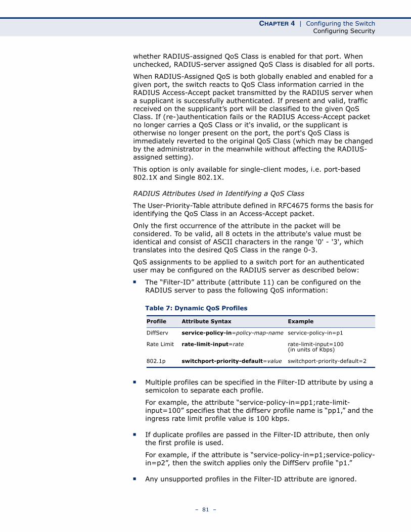
CHAPTER 4 | Configuring the SwitchConfiguring Security
whether RADIUS-assigned QoS Class is enabled for that port. When unchecked, RADIUS-server assigned QoS Class is disabled for all ports.
When RADIUS-Assigned QoS is both globally enabled and enabled for a given port, the switch reacts to QoS Class information carried in the RADIUS Access-Accept packet transmitted by the RADIUS server when a supplicant is successfully authenticated. If present and valid, traffic received on the supplicant’s port will be classified to the given QoS Class. If (re-)authentication fails or the RADIUS Access-Accept packet no longer carries a QoS Class or it's invalid, or the supplicant is otherwise no longer present on the port, the port's QoS Class is immediately reverted to the original QoS Class (which may be changed by the administrator in the meanwhile without affecting the RADIUS-assigned setting).
This option is only available for single-client modes, i.e. port-based 802.1X and Single 802.1X.
RADIUS Attributes Used in Identifying a QoS Class
The User-Priority-Table attribute defined in RFC4675 forms the basis for identifying the QoS Class in an Access-Accept packet.
Only the first occurrence of the attribute in the packet will be considered. To be valid, all 8 octets in the attribute's value must be identical and consist of ASCII characters in the range '0' - '3', which translates into the desired QoS Class in the range 0-3.
QoS assignments to be applied to a switch port for an authenticated user may be configured on the RADIUS server as described below:
■ The “Filter-ID” attribute (attribute 11) can be configured on the RADIUS server to pass the following QoS information:
■ Multiple profiles can be specified in the Filter-ID attribute by using a semicolon to separate each profile.
For example, the attribute “service-policy-in=pp1;rate-limit-input=100” specifies that the diffserv profile name is “pp1,” and the ingress rate limit profile value is 100 kbps.
■ If duplicate profiles are passed in the Filter-ID attribute, then only the first profile is used.
For example, if the attribute is “service-policy-in=p1;service-policy-in=p2”, then the switch applies only the DiffServ profile “p1.”
■ Any unsupported profiles in the Filter-ID attribute are ignored.
Table 7: Dynamic QoS Profiles
Profile Attribute Syntax Example
DiffServ service-policy-in=policy-map-name service-policy-in=p1
Rate Limit rate-limit-input=rate rate-limit-input=100 (in units of Kbps)
802.1p switchport-priority-default=value switchport-priority-default=2
– 81 –
CHAPTER 4 | Configuring the SwitchConfiguring Security
For example, if the attribute is “map-ip-dscp=2:3;service-policy-in=p1,” then the switch ignores the “map-ip-dscp” profile.
■ When authentication is successful, the dynamic QoS information may not be passed from the RADIUS server due to one of the following conditions (authentication result remains unchanged):
■ The Filter-ID attribute cannot be found to carry the user profile.
■ The Filter-ID attribute is empty.
■ The Filter-ID attribute format for dynamic QoS assignment is unrecognizable (can not recognize the whole Filter-ID attribute).
■ Dynamic QoS assignment fails and the authentication result changes from success to failure when the following conditions occur:
■ Illegal characters found in a profile value (for example, a non-digital character in an 802.1p profile value).
■ Failure to configure the received profiles on the authenticated port.
■ When the last user logs off on a port with a dynamic QoS assignment, the switch restores the original QoS configuration for the port.
■ When a user attempts to log into the network with a returned dynamic QoS profile that is different from users already logged on to the same port, the user is denied access.
■ While a port has an assigned dynamic QoS profile, any manual QoS configuration changes only take effect after all users have logged off the port.
◆ RADIUS-Assigned VLAN Enabled - RADIUS-assigned VLAN provides a means to centrally control the VLAN on which a successfully authenticated supplicant is placed on the switch. Incoming traffic will be classified to and switched on the RADIUS-assigned VLAN. The RADIUS server must be configured to transmit special RADIUS attributes to take advantage of this feature.
The “RADIUS-Assigned VLAN Enabled” checkbox provides a quick way to globally enable/disable RADIUS-server assigned VLAN functionality. When checked, the individual port settings determine whether RADIUS-assigned VLAN is enabled for that port. When unchecked, RADIUS-server assigned VLAN is disabled for all ports.
When RADIUS-Assigned VLAN is both globally enabled and enabled for a given port, the switch reacts to VLAN ID information carried in the RADIUS Access-Accept packet transmitted by the RADIUS server when a supplicant is successfully authenticated. If present and valid, the port's Port VLAN ID will be changed to this VLAN ID, the port will be set to be a member of that VLAN ID, and the port will be forced into VLAN-unaware mode. Once assigned, all traffic arriving on the port will be classified and switched on the RADIUS-assigned VLAN ID.
– 82 –
CHAPTER 4 | Configuring the SwitchConfiguring Security
If (re-)authentication fails or the RADIUS Access-Accept packet no longer carries a VLAN ID or it's invalid, or the supplicant is otherwise no longer present on the port, the port's VLAN ID is immediately reverted to the original VLAN ID (which may be changed by the administrator in the meanwhile without affecting the RADIUS-assigned setting).
This option is only available for single-client modes, i.e. port-based 802.1X and Single 802.1X.
NOTE: For trouble-shooting VLAN assignments, use the Monitor > VLANs > VLAN Membership and VLAN Port pages. These pages show which modules have (temporarily) overridden the current Port VLAN configuration.
RADIUS Attributes Used in Identifying a VLAN ID
RFC 2868 and RFC 3580 form the basis for the attributes used in identifying a VLAN ID in an Access-Accept packet. The following criteria are used:
■ The Tunnel-Medium-Type, Tunnel-Type, and Tunnel-Private-Group-ID attributes must all be present at least once in the Access-Accept packet.
■ The switch looks for the first set of these attributes that have the same Tag value and fulfil the following requirements (if Tag == 0 is used, the Tunnel-Private-Group-ID does not need to include a Tag):
■ Value of Tunnel-Medium-Type must be set to “IEEE-802” (ordinal 6).
■ Value of Tunnel-Type must be set to “VLAN” (ordinal 13).
■ Value of Tunnel-Private-Group-ID must be a string of ASCII characters in the range 0-9, which is interpreted as a decimal string representing the VLAN ID. Leading '0's are discarded. The final value must be in the range 1-4095.
The VLAN list can contain multiple VLAN identifiers in the format “1u,2t,3u” where “u” indicates an untagged VLAN and “t” a tagged VLAN.
◆ Guest VLAN Enabled - A Guest VLAN is a special VLAN - typically with limited network access - on which 802.1X-unaware clients are placed after a network administrator-defined timeout. The switch follows a set of rules for entering and leaving the Guest VLAN as listed below.
The “Guest VLAN Enabled” checkbox provides a quick way to globally enable/disable Guest VLAN functionality. When checked, the individual port settings determine whether the port can be moved into Guest VLAN. When unchecked, the ability to move to the Guest VLAN is disabled for all ports.
When Guest VLAN is both globally enabled and enabled for a given port, the switch considers moving the port into the Guest VLAN according to the rules outlined below. This option is only available for EAPOL-based modes, i.e. Port-based 802.1X, Single 802.1X, and Multi 802.1X
– 83 –
CHAPTER 4 | Configuring the SwitchConfiguring Security
NOTE: For trouble-shooting VLAN assignments, use the Monitor > VLANs > VLAN Membership and VLAN Port pages. These pages show which modules have (temporarily) overridden the current Port VLAN configuration.
Guest VLAN Operation
When a Guest VLAN enabled port's link comes up, the switch starts transmitting EAPOL Request Identity frames. If the number of transmissions of such frames exceeds Max. Reauth. Count and no EAPOL frames have been received in the meanwhile, the switch considers entering the Guest VLAN. The interval between transmission of EAPOL Request Identity frames is configured with EAPOL Timeout. If Allow Guest VLAN if EAPOL Seen is enabled, the port will now be placed in the Guest VLAN. If disabled, the switch will first check its history to see if an EAPOL frame has previously been received on the port (this history is cleared if the port link goes down or the port's Admin State is changed), and if not, the port will be placed in the Guest VLAN. Otherwise it will not move to the Guest VLAN, but continue transmitting EAPOL Request Identity frames at the rate given by EAPOL Timeout.
Once in the Guest VLAN, the port is considered authenticated, and all attached clients on the port are allowed access on this VLAN. The switch will not transmit an EAPOL Success frame after entering the Guest VLAN.
While in the Guest VLAN, the switch monitors the link for EAPOL frames, and if one such frame is received, the switch immediately takes the port out of the Guest VLAN and starts authenticating the supplicant according to the port mode. If an EAPOL frame is received, the port will never be able to go back into the Guest VLAN if the “Allow Guest VLAN if EAPOL Seen” is disabled.
◆ Guest VLAN ID - This is the value that a port's Port VLAN ID is set to if a port is moved into the Guest VLAN. It is only changeable if the Guest VLAN option is globally enabled. (Range: 1-4095)
◆ Max. Reauth. Count - The number of times that the switch transmits an EAPOL Request Identity frame without receiving a response before adding a port to the Guest VLAN. The value can only be changed if the Guest VLAN option is globally enabled. (Range: 1-255)
◆ Allow Guest VLAN if EAPOL Seen - The switch remembers if an EAPOL frame has been received on the port for the lifetime of the port. Once the switch considers whether to enter the Guest VLAN, it will first check if this option is enabled or disabled. If disabled (the default), the switch will only enter the Guest VLAN if an EAPOL frame has not been received on the port for the lifetime of the port. If enabled, the switch will consider entering the Guest VLAN even if an EAPOL frame has been received on the port for the lifetime of the port. The value can only be changed if the Guest VLAN option is globally enabled.
– 84 –
CHAPTER 4 | Configuring the SwitchConfiguring Security
Port Configuration
◆ Port – Port identifier.
◆ Admin State - If NAS is globally enabled, this selection controls the port's authentication mode. The following modes are available:
■ Force Authorized - The switch sends one EAPOL Success frame when the port link comes up. This forces the port to grant access to all clients, either dot1x-aware or otherwise. (This is the default setting.)
■ Force Unauthorized - The switch will send one EAPOL Failure frame when the port link comes up. This forces the port to deny access to all clients, either dot1x-aware or otherwise.
■ Port-based 802.1X - Requires a dot1x-aware client to be authorized by the authentication server. Clients that are not dot1x-aware will be denied access.
■ Single 802.1X - At most one supplicant can get authenticated on the port at a time. If more than one supplicant is connected to a port, the one that comes first when the port's link comes up will be the first one considered. If that supplicant doesn't provide valid credentials within a certain amount of time, another supplicant will get a chance. Once a supplicant is successfully authenticated, only that supplicant will be allowed access. This is the most secure of all the supported modes. In this mode, the Port Security module is used to secure a supplicant's MAC address once successfully authenticated.
■ Multi 802.1X - One or more supplicants can get authenticated on the same port at the same time. Each supplicant is authenticated individually and secured in the MAC table using the Port Security module.
In Multi 802.1X it is not possible to use the multicast BPDU MAC address as the destination MAC address for EAPOL frames sent from the switch towards the supplicant, since that would cause all supplicants attached to the port to reply to requests sent from the switch. Instead, the switch uses the supplicant's MAC address, which is obtained from the first EAPOL Start or EAPOL Response Identity frame sent by the supplicant. An exception to this is when no supplicants are attached. In this case, the switch sends EAPOL Request Identity frames using the BPDU multicast MAC address as the destination - to wake up any supplicants that might be on the port.
The maximum number of supplicants that can be attached to a port can be limited using the Port Security Limit Control functionality.
■ MAC-based Auth. - Enables MAC-based authentication on the port. The switch does not transmit or accept EAPOL frames on the port. Flooded frames and broadcast traffic will be transmitted on the port, whether or not clients are authenticated on the port, whereas unicast traffic from an unsuccessfully authenticated client will be dropped. Clients that are not (or not yet) successfully authenticated will not be allowed to transmit frames of any kind.
– 85 –
CHAPTER 4 | Configuring the SwitchConfiguring Security
The switch acts as the supplicant on behalf of clients. The initial frame (any kind of frame) sent by a client is snooped by the switch, which in turn uses the client's MAC address as both user name and password in the subsequent EAP exchange with the RADIUS server. The 6-byte MAC address is converted to a string on the following form “xx-xx-xx-xx-xx-xx”, that is, a dash (-) is used as separator between the lower-cased hexadecimal digits. The switch only supports the MD5-Challenge authentication method, so the RADIUS server must be configured accordingly.
When authentication is complete, the RADIUS server sends a success or failure indication, which in turn causes the switch to open up or block traffic for that particular client, using the Port Security module. Only then will frames from the client be forwarded on the switch. There are no EAPOL frames involved in this authentication, and therefore, MAC-based Authentication has nothing to do with the 802.1X standard.
The advantage of MAC-based authentication over port-based 802.1X is that several clients can be connected to the same port (e.g. through a 3rd party switch or a hub) and still require individual authentication, and that the clients don't need special supplicant software to authenticate. The advantage of MAC-based authentication over 802.1X-based authentication is that the clients don't need special supplicant software to authenticate. The disadvantage is that MAC addresses can be spoofed by malicious users - equipment whose MAC address is a valid RADIUS user can be used by anyone. Also, only the MD5-Challenge method is supported. The maximum number of clients that can be attached to a port can be limited using the Port Security Limit Control functionality.
Further Guidelines for Port Admin State
■ Port Admin state can only be set to Force-Authorized for ports participating in the Spanning Tree algorithm (see page 125).
■ When 802.1X authentication is enabled on a port, the MAC address learning function for this interface is disabled, and the addresses dynamically learned on this port are removed from the common address table.
■ Authenticated MAC addresses are stored as dynamic entries in the switch's secure MAC address table. Configured static MAC addresses are added to the secure address table when seen on a switch port (see page 157). Static addresses are treated as authenticated without sending a request to a RADIUS server.
■ When port status changes to down, all MAC addresses are cleared from the secure MAC address table. Static VLAN assignments are not restored.
◆ RADIUS-Assigned QoS Enabled - Enables or disables this feature for a given port. Refer to the description of this feature under the System Configuration section.
– 86 –
CHAPTER 4 | Configuring the SwitchConfiguring Security
◆ RADIUS-Assigned VLAN Enabled - Enables or disables this feature for a given port. Refer to the description of this feature under the System Configuration section.
◆ Guest VLAN Enabled - Enables or disables this feature for a given port. Refer to the description of this feature under the System Configure section.
◆ Port State - The current state of the port:
■ Globally Disabled - 802.1X and MAC-based authentication are globally disabled. (This is the default state.)
■ Link Down - 802.1X or MAC-based authentication is enabled, but there is no link on the port.
■ Authorized - The port is in Force Authorized mode, or a single-supplicant mode and the supplicant is authorized.
■ Unauthorized - The port is in Force Unauthorized mode, or a single-supplicant mode and the supplicant is not successfully authorized by the RADIUS server.
■ X Auth/Y Unauth - The port is in a multi-supplicant mode. X clients are currently authorized and Y are unauthorized.
◆ Restart - Restarts client authentication using one of the methods described below. Note that the restart buttons are only enabled when the switch’s authentication mode is globally enabled (under System Configuration) and the port's Admin State is an EAPOL-based or MAC-Based mode. Clicking these buttons will not cause settings changed on the page to take effect.
■ Reauthenticate - Schedules reauthentication to whenever the quiet-period of the port runs out (EAPOL-based authentication). For MAC-based authentication, reauthentication will be attempted immediately. The button only has effect for successfully authenticated clients on the port and will not cause the clients to get temporarily unauthorized.
■ Reinitialize - Forces a reinitialization of the clients on the port and thereby a reauthentication immediately. The clients will transfer to the unauthorized state while the reauthentication is in progress.
WEB INTERFACETo configure 802.1X Port Security:
1. Click Configuration, Security, Network, NAS.
2. Modify the required attributes.
3. Click Save.
– 87 –
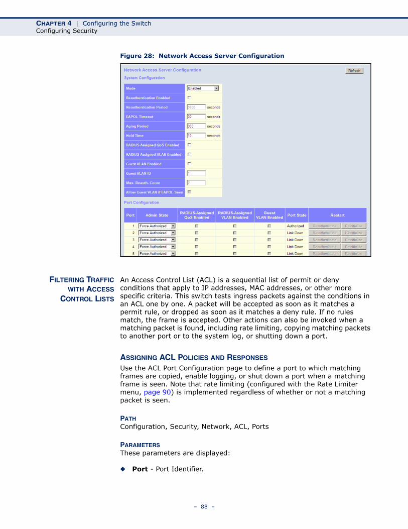
CHAPTER 4 | Configuring the SwitchConfiguring Security
Figure 28: Network Access Server Configuration
FILTERING TRAFFICWITH ACCESS
CONTROL LISTS
An Access Control List (ACL) is a sequential list of permit or deny conditions that apply to IP addresses, MAC addresses, or other more specific criteria. This switch tests ingress packets against the conditions in an ACL one by one. A packet will be accepted as soon as it matches a permit rule, or dropped as soon as it matches a deny rule. If no rules match, the frame is accepted. Other actions can also be invoked when a matching packet is found, including rate limiting, copying matching packets to another port or to the system log, or shutting down a port.
ASSIGNING ACL POLICIES AND RESPONSES Use the ACL Port Configuration page to define a port to which matching frames are copied, enable logging, or shut down a port when a matching frame is seen. Note that rate limiting (configured with the Rate Limiter menu, page 90) is implemented regardless of whether or not a matching packet is seen.
PATH Configuration, Security, Network, ACL, Ports
PARAMETERSThese parameters are displayed:
◆ Port - Port Identifier.
– 88 –
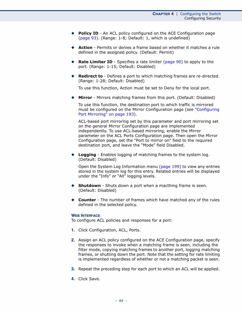
CHAPTER 4 | Configuring the SwitchConfiguring Security
◆ Policy ID - An ACL policy configured on the ACE Configuration page (page 93). (Range: 1-8; Default: 1, which is undefined)
◆ Action - Permits or denies a frame based on whether it matches a rule defined in the assigned policy. (Default: Permit)
◆ Rate Limiter ID - Specifies a rate limiter (page 90) to apply to the port. (Range: 1-15; Default: Disabled)
◆ Redirect to - Defines a port to which matching frames are re-directed. (Range: 1-28; Default: Disabled)
To use this function, Action must be set to Deny for the local port.
◆ Mirror - Mirrors matching frames from this port. (Default: Disabled)
To use this function, the destination port to which traffic is mirrored must be configured on the Mirror Configuration page (see "Configuring Port Mirroring" on page 193).
ACL-based port mirroring set by this parameter and port mirroring set on the general Mirror Configuration page are implemented independently. To use ACL-based mirroring, enable the Mirror parameter on the ACL Ports Configuration page. Then open the Mirror Configuration page, set the “Port to mirror on” field to the required destination port, and leave the “Mode” field Disabled.
◆ Logging - Enables logging of matching frames to the system log. (Default: Disabled)
Open the System Log Information menu (page 199) to view any entries stored in the system log for this entry. Related entries will be displayed under the “Info” or “All” logging levels.
◆ Shutdown - Shuts down a port when a macthing frame is seen. (Default: Disabled)
◆ Counter - The number of frames which have matched any of the rules defined in the selected policy.
WEB INTERFACETo configure ACL policies and responses for a port:
1. Click Configuration, ACL, Ports.
2. Assign an ACL policy configured on the ACE Configuration page, specify the responses to invoke when a matching frame is seen, including the filter mode, copying matching frames to another port, logging matching frames, or shutting down the port. Note that the setting for rate limiting is implemented regardless of whether or not a matching packet is seen.
3. Repeat the preceding step for each port to which an ACL will be applied.
4. Click Save.
– 89 –
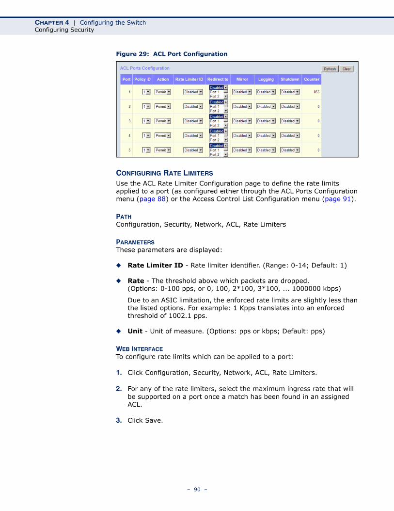
CHAPTER 4 | Configuring the SwitchConfiguring Security
Figure 29: ACL Port Configuration
CONFIGURING RATE LIMITERS Use the ACL Rate Limiter Configuration page to define the rate limits applied to a port (as configured either through the ACL Ports Configuration menu (page 88) or the Access Control List Configuration menu (page 91).
PATH Configuration, Security, Network, ACL, Rate Limiters
PARAMETERSThese parameters are displayed:
◆ Rate Limiter ID - Rate limiter identifier. (Range: 0-14; Default: 1)
◆ Rate - The threshold above which packets are dropped. (Options: 0-100 pps, or 0, 100, 2*100, 3*100, ... 1000000 kbps)
Due to an ASIC limitation, the enforced rate limits are slightly less than the listed options. For example: 1 Kpps translates into an enforced threshold of 1002.1 pps.
◆ Unit - Unit of measure. (Options: pps or kbps; Default: pps)
WEB INTERFACETo configure rate limits which can be applied to a port:
1. Click Configuration, Security, Network, ACL, Rate Limiters.
2. For any of the rate limiters, select the maximum ingress rate that will be supported on a port once a match has been found in an assigned ACL.
3. Click Save.
– 90 –
CHAPTER 4 | Configuring the SwitchConfiguring Security
Figure 30: ACL Rate Limiter Configuration
CONFIGURING ACCESS CONTROL LISTS Use the Access Control List Configuration page to define filtering rules for an ACL policy, for a specific port, or for all ports. Rules applied to a port take effect immediately, while those defined for a policy must be mapped to one or more ports using the ACL Ports Configuration menu (page 88).
PATH Configuration, Security, Network, ACL, Access Control List
USAGE GUIDELINES◆ Rules within an ACL are checked in the configured order, from top to
bottom. A packet will be accepted as soon as it matches a permit rule, or dropped as soon as it matches a deny rule. If no rules match, the frame is accepted.
◆ The maximum number of ACL rules that can be configured on the switch is 128.
◆ The maximum number of ACL rules that can be bound to a port is 10.
◆ ACLs provide frame filtering based on any of the following criteria:
■ Any frame type (based on MAC address, VLAN ID, VLAN priority)
■ Ethernet type (based on Ethernet type value, MAC address, VLAN ID, VLAN priority)
■ ARP (based on ARP/RARP type, request/reply, sender/target IP, hardware address matches ARP/RARP MAC address, ARP/RARP hardware address length matches protocol address length, matches this entry when ARP/RARP hardware address is equal to Ethernet,
– 91 –
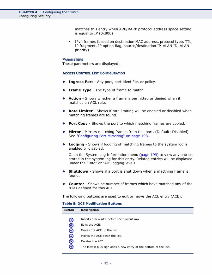
CHAPTER 4 | Configuring the SwitchConfiguring Security
matches this entry when ARP/RARP protocol address space setting is equal to IP (0x800)
■ IPv4 frames (based on destination MAC address, protocol type, TTL, IP fragment, IP option flag, source/destination IP, VLAN ID, VLAN priority)
PARAMETERSThese parameters are displayed:
ACCESS CONTROL LIST CONFIGURATION
◆ Ingress Port - Any port, port identifier, or policy.
◆ Frame Type - The type of frame to match.
◆ Action - Shows whether a frame is permitted or denied when it matches an ACL rule.
◆ Rate Limiter - Shows if rate limiting will be enabled or disabled when matching frames are found.
◆ Port Copy - Shows the port to which matching frames are copied.
◆ Mirror - Mirrors matching frames from this port. (Default: Disabled) See "Configuring Port Mirroring" on page 193.
◆ Logging - Shows if logging of matching frames to the system log is enabled or disabled.
Open the System Log Information menu (page 199) to view any entries stored in the system log for this entry. Related entries will be displayed under the “Info” or “All” logging levels.
◆ Shutdown - Shows if a port is shut down when a macthing frame is found.
◆ Counter - Shows he number of frames which have matched any of the rules defined for this ACL.
The following buttons are used to edit or move the ACL entry (ACE):
Table 8: QCE Modification Buttons
Button Description
Inserts a new ACE before the current row.
Edits the ACE.
Moves the ACE up the list.
Moves the ACE down the list.
Deletes the ACE.
The lowest plus sign adds a new entry at the bottom of the list.
– 92 –
CHAPTER 4 | Configuring the SwitchConfiguring Security
ACE CONFIGURATION
Ingress Port and Frame Type
◆ Ingress Port - Any port, port identifier, or policy. (Options: Any port, Port 1-10, Policy 1-8; Default: Any)
◆ Frame Type - The type of frame to match. (Options: Any, Ethernet, ARP, IPv4; Default: Any)
Filter Criteria Based on Selected Frame Type
◆ Ethernet:
MAC Parameters
■ SMAC Filter - The type of source MAC address. (Options: Any, Specific - user defined; Default: Any)
■ DMAC Filter - The type of destination MAC address. (Options: Any, MC - multicast, BC - broadcast, UC - unicast, Specific - user defined; Default: Any)
Ethernet Type Parameters
■ EtherType Filter - This option can only be used to filter Ethernet II formatted packets. (Options: Any, Specific (600-ffff hex); Default: Any)
A detailed listing of Ethernet protocol types can be found in RFC 1060. A few of the more common types include 0800 (IP), 0806 (ARP), 8137 (IPX).
◆ ARP:
MAC Parameters
■ SMAC Filter - The type of source MAC address. (Options: Any, Specific - user defined; Default: Any)
■ DMAC Filter - The type of destination MAC address. (Options: Any, MC - multicast, BC - broadcast, UC - unicast; Default: Any)
ARP Parameters
■ ARP/RARP - Specifies the type of ARP packet. (Options: Any - no ARP/RARP opcode flag is specified, ARP - frame must have ARP/RARP opcode set to ARP, RARP - frame must have ARP/RARP opcode set to RARP, Other - frame has unknown ARP/RARP opcode flag; Default: Any)
■ Request/Reply - Specifies whether the packet is an ARP request, reply, or either type. (Options: Any - no ARP/RARP opcode flag is specified, Request - frame must have ARP Request or RARP Request
– 93 –

CHAPTER 4 | Configuring the SwitchConfiguring Security
opcode flag set, Reply - frame must have ARP Reply or RARP Reply opcode flag; Default: Any)
■ Sender IP Filter - Specifies the sender’s IP address. (Options: Any - no sender IP filter is specified, Host - specifies the sender IP address in the SIP Address field, Network - specifies the sender IP address and sender IP mask in the SIP Address and SIP Mask fields; Default: Any)
■ Target IP Filter - Specifies the destination IP address. (Options: Any - no target IP filter is specified, Host - specifies the target IP address in the Target IP Address field, Network - specifies the target IP address and target IP mask in the Target IP Address and Target IP Mask fields; Default: Any)
■ ARP SMAC Match - Specifies whether frames can be matched according to their sender hardware address (SHA) field settings. (0ptions: Any - any value is allowed, 0 - ARP frames where SHA is not equal to the SMAC address, 1 - ARP frames where SHA is equal to the SMAC address; Default: Any)
■ RARP DMAC Match - Specifies whether frames can be matched according to their target hardware address (THA) field settings. (Options: Any - any value is allowed, 0 - RARP frames where THA is not equal to the DMAC address, 1 - RARP frames where THA is equal to the DMAC address; Default: Any)
■ IP/Ethernet Length - Specifies whether frames can be matched according to their ARP/RARP hardware address length (HLN) and protocol address length (PLN) settings. (Options: Any - any value is allowed, 0 - ARP/RARP frames where the HLN is equal to Ethernet (0x06) and the (PLN) is equal to IPv4 (0x04) must not match this entry, 1 - ARP/RARP frames where the HLN is equal to Ethernet (0x06) and the (PLN) is equal to IPv4 (0x04) must match this entry; Default: Any)
■ IP - Specifies whether frames can be matched according to their ARP/RARP hardware address space (HRD) settings. (Options: Any - any value is allowed, 0 - ARP/RARP frames where the HRD is equal to Ethernet (1) must not match this entry, 1 - ARP/RARP frames where the HRD is equal to Ethernet (1) must match this entry; Default: Any)
■ Ethernet - Specifies whether frames can be matched according to their ARP/RARP protocol address space (PRO) settings. (Options: Any - any value is allowed, 0 - ARP/RARP frames where the PRO is equal to IP (0x800) must not match this entry, 1 - ARP/RARP frames where the PRO is equal to IP (0x800) must match this entry; Default: Any)
– 94 –
CHAPTER 4 | Configuring the SwitchConfiguring Security
◆ IPv4:
MAC Parameters
■ DMAC Filter - The type of destination MAC address. (Options: Any, MC - multicast, BC - broadcast, UC - unicast; Default: Any)
IP Parameters
■ IP Protocol Filter - Specifies the IP protocol to filter for this rule. (Options: Any, ICMP, UDP, TCP, Other; Default: Any)
The following additional fields are displayed when these protocol filters are selected.
ICMP Parameters
■ ICMP Type Filter - Specifies the type of ICMP packet to filter for this rule. (Options: Any, Specific: 0-255; Default: Any)
■ ICMP Code Filter - Specifies the ICMP code of an ICMP packet to filter for this rule. (Options: Any, Specific (0-255); Default: Any)
UDP Parameters
■ Source Port Filter - Specifies the UDP source filter for this rule. (Options: Any, Specific (0-65535), Range (0-65535); Default: Any)
■ Dest. Port Filter - Specifies the UDP destination filter for this rule. (Options: Any, Specific (0-65535), Range (0-65535); Default: Any)
TCP Parameters
■ Source Port Filter - Specifies the TCP source filter for this rule. (Options: Any, Specific (0-65535), Range (0-65535); Default: Any)
■ Dest. Port Filter - Specifies the TCP destination filter for this rule. (Options: Any, Specific (0-65535), Range (0-65535); Default: Any)
■ TCP FIN - Specifies the TCP “No more data from sender” (FIN) value for this rule. (Options: Any - any value is allowed, 0 - TCP frames where the FIN field is set must not match this entry, 1 - TCP frames where the FIN field is set must match this entry; Default: Any)
■ TCP SYN - Specifies the TCP “Synchronize sequence numbers” (SYN) value for this rule. (Options: Any - any value is allowed, 0 - TCP frames where the SYN field is set must not match this
– 95 –
CHAPTER 4 | Configuring the SwitchConfiguring Security
entry, 1 - TCP frames where the SYN field is set must match this entry; Default: Any)
■ TCP RST - Specifies the TCP “Reset the connection” (RST) value for this rule. (Options: Any - any value is allowed, 0 - TCP frames where the RST field is set must not match this entry, 1 - TCP frames where the RST field is set must match this entry; Default: Any)
■ TCP PSH - Specifies the TCP “Push Function” (PSH) value for this rule. (Options: Any - any value is allowed, 0 - TCP frames where the PSH field is set must not match this entry, 1 - TCP frames where the PSH field is set must match this entry; Default: Any)
■ TCP ACK - Specifies the TCP “Acknowledgment field significant” (ACK) value for this rule. (Options: Any - any value is allowed, 0 - TCP frames where the ACK field is set must not match this entry, 1 - TCP frames where the ACK field is set must match this entry; Default: Any)
■ TCP URG - Specifies the TCP “Urgent Pointer field significant” (URG) value for this rule. (Options: Any - any value is allowed, 0 - TCP frames where the URG field is set must not match this entry, 1 - TCP frames where the URG field is set must match this entry; Default: Any)
■ IP TTL - Specifies the time-to-Live settings for this rule. (Options: Any - any value is allowed, Non-zero - IPv4 frames with a TTL field greater than zero must match this entry, Zero - IPv4 frames with a TTL field greater than zero must not match this entry; Default: Any)
■ IP Fragment - Specifies the fragment offset settings for this rule. This involves the settings for the More Fragments (MF) bit and the Fragment Offset (FRAG OFFSET) field for an IPv4 frame. (Options: Any - any value is allowed, Yes - IPv4 frames where the MF bit is set or the FRAG OFFSET field is greater than zero must match this entry, No - IPv4 frames where the MF bit is set or the FRAG OFFSET field is greater than zero must not match this entry; Default: Any)
■ IP Option - Specifies the options flag setting for this rule. (Options: Any - any value is allowed, Yes - IPv4 frames where the options flag is set must match this entry, No - IPv4 frames where the options flag is set must not match this entry; Default: Any)
■ SIP Filter - Specifies the source IP filter for this rule. (Options: Any - no source IP filter is specified, Host - specifies the source IP address in the SIP Address field, Network - specifies the source IP address and source IP mask in the SIP Address and SIP Mask fields; Default: Any)
■ DIP Filter - Specifies the destination IP filter for this rule. (Options: Any - no destination IP filter is specified, Host - specifies the destination IP address in the DIP Address field, Network -
– 96 –
CHAPTER 4 | Configuring the SwitchConfiguring Security
specifies the destination IP address and destination IP mask in the DIP Address and DIP Mask fields; Default: Any)
Response to take when a rule is matched
◆ Action - Permits or denies a frame based on whether it matches an ACL rule. (Default: Permit)
◆ Rate Limiter - Specifies a rate limiter (page 90) to apply to the port. (Range: 1-16; Default: Disabled)
◆ Port Copy - Defines a port to which matching frames are copied. (Range: 1-10; Default: Disabled)
◆ Mirror - Mirrors matching frames from this port. (Default: Disabled) See "Configuring Port Mirroring" on page 193.
ACL-based port mirroring set by this parameter and port mirroring set on the general Mirror Configuration page are implemented independently. To use ACL-based mirroring, enable the Mirror parameter on the ACE Configuration page. Then open the Mirror Configuration page, set the “Port to mirror on” field to the required destination port, and leave the “Mode” field Disabled.
◆ Logging - Enables logging of matching frames to the system log. (Default: Disabled)
Open the System Log Information menu (page 199) to view any entries stored in the system log for this entry. Related entries will be displayed under the “Info” or “All” logging levels.
◆ Shutdown - Shuts down a port when a macthing frame is seen. (Default: Disabled)
◆ Counter - Shows he number of frames which have matched any of the rules defined for this ACL.
VLAN Parameters
◆ 802.1Q Tagged - Specifies whether or not frames should be 802.1Q tagged. (Options: Any, Disabled, Enabled; Default: Any)
◆ VLAN ID Filter - Specifies the VLAN to filter for this rule. (Options: Any, Specific (1-4095); Default: Any)
◆ Tag Priority - Specifies the User Priority value found in the VLAN tag (3 bits as defined by IEEE 802.1p) to match for this rule. (Options: Any, Specific (0-7); Default: Any)
– 97 –
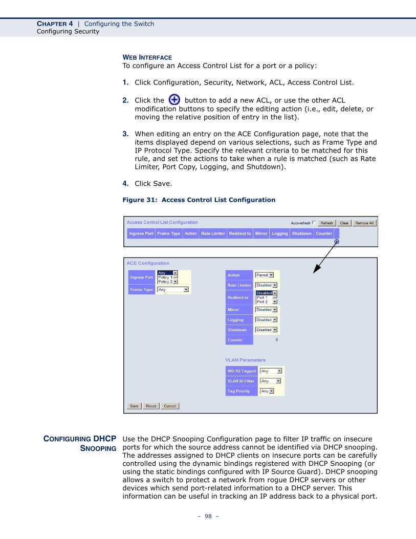
CHAPTER 4 | Configuring the SwitchConfiguring Security
WEB INTERFACETo configure an Access Control List for a port or a policy:
1. Click Configuration, Security, Network, ACL, Access Control List.
2. Click the button to add a new ACL, or use the other ACL modification buttons to specify the editing action (i.e., edit, delete, or moving the relative position of entry in the list).
3. When editing an entry on the ACE Configuration page, note that the items displayed depend on various selections, such as Frame Type and IP Protocol Type. Specify the relevant criteria to be matched for this rule, and set the actions to take when a rule is matched (such as Rate Limiter, Port Copy, Logging, and Shutdown).
4. Click Save.
Figure 31: Access Control List Configuration
CONFIGURING DHCPSNOOPING
Use the DHCP Snooping Configuration page to filter IP traffic on insecure ports for which the source address cannot be identified via DHCP snooping. The addresses assigned to DHCP clients on insecure ports can be carefully controlled using the dynamic bindings registered with DHCP Snooping (or using the static bindings configured with IP Source Guard). DHCP snooping allows a switch to protect a network from rogue DHCP servers or other devices which send port-related information to a DHCP server. This information can be useful in tracking an IP address back to a physical port.
– 98 –
CHAPTER 4 | Configuring the SwitchConfiguring Security
PATH Configuration, Security, Network, DHCP, Snooping
COMMAND USAGE
DHCP Snooping Process
◆ Network traffic may be disrupted when malicious DHCP messages are received from an outside source. DHCP snooping is used to filter DHCP messages received on a non-secure interface from outside the network or fire wall. When DHCP snooping is enabled globally and enabled on a VLAN interface, DHCP messages received on an untrusted interface from a device not listed in the DHCP snooping table will be dropped.
◆ Table entries are only learned for trusted interfaces. An entry is added or removed dynamically to the DHCP snooping table when a client receives or releases an IP address from a DHCP server. Each entry includes a MAC address, IP address, lease time, VLAN identifier, and port identifier.
◆ When DHCP snooping is enabled, DHCP messages entering an untrusted interface are filtered based upon dynamic entries learned via DHCP snooping.
◆ Filtering rules are implemented as follows:
■ If the global DHCP snooping is disabled, all DHCP packets are forwarded.
■ If DHCP snooping is enabled globally, all DHCP packets are forwarded for a trusted port. If the received packet is a DHCP ACK message, a dynamic DHCP snooping entry is also added to the binding table.
■ If DHCP snooping is enabled globally, but the port is not trusted, it is processed as follows:
■ If the DHCP packet is a reply packet from a DHCP server (including OFFER, ACK or NAK messages), the packet is dropped.
■ If a DHCP DECLINE or RELEASE message is received from a client, the switch forwards the packet only if the corresponding entry is found in the binding table.
■ If a DHCP DISCOVER, REQUEST or INFORM message is received from a client, the packet is forwarded.
■ If the DHCP packet is not a recognizable type, it is dropped.
■ If a DHCP packet from a client passes the filtering criteria above, it will only be forwarded to trusted ports in the same VLAN.
■ If a DHCP packet is from server is received on a trusted port, it will be forwarded to both trusted and untrusted ports in the same VLAN.
– 99 –
CHAPTER 4 | Configuring the SwitchConfiguring Security
■ If the DHCP snooping is globally disabled, all dynamic bindings are removed from the binding table.
■ Additional considerations when the switch itself is a DHCP client – The port(s) through which the switch submits a client request to the DHCP server must be configured as trusted. Note that the switch will not add a dynamic entry for itself to the binding table when it receives an ACK message from a DHCP server. Also, when the switch sends out DHCP client packets for itself, no filtering takes place. However, when the switch receives any messages from a DHCP server, any packets received from untrusted ports are dropped.
PARAMETERSThese parameters are displayed:
◆ Snooping Mode – Enables DHCP snooping globally. When DHCP snooping is enabled, DHCP request messages will be forwarded to trusted ports, and reply packets only allowed from trusted ports. (Default: Disabled)
◆ Port – Port identifier
◆ Mode – Enables or disables a port as a trusted source of DHCP messages. (Default: Trusted)
WEB INTERFACETo configure DHCP Snooping:
1. Click Configuration, Security, Network, DHCP, Snooping.
2. Set the status for the global DHCP snooping process, and set any ports within the local network or firewall to trusted.
3. Click Apply
– 100 –
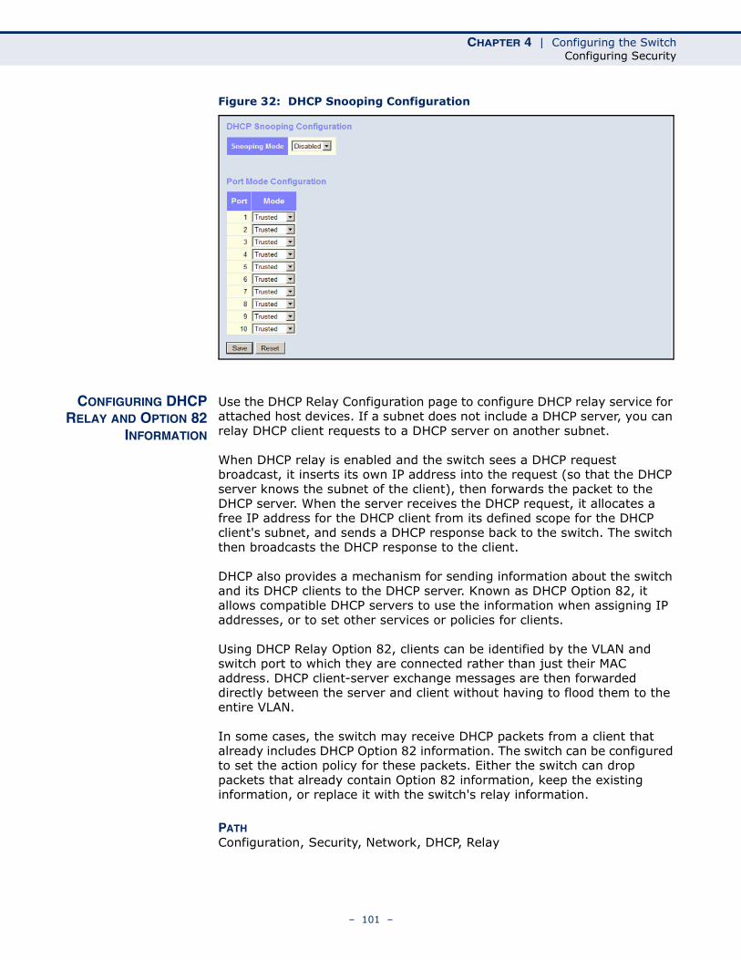
CHAPTER 4 | Configuring the SwitchConfiguring Security
Figure 32: DHCP Snooping Configuration
CONFIGURING DHCPRELAY AND OPTION 82
INFORMATION
Use the DHCP Relay Configuration page to configure DHCP relay service for attached host devices. If a subnet does not include a DHCP server, you can relay DHCP client requests to a DHCP server on another subnet.
When DHCP relay is enabled and the switch sees a DHCP request broadcast, it inserts its own IP address into the request (so that the DHCP server knows the subnet of the client), then forwards the packet to the DHCP server. When the server receives the DHCP request, it allocates a free IP address for the DHCP client from its defined scope for the DHCP client's subnet, and sends a DHCP response back to the switch. The switch then broadcasts the DHCP response to the client.
DHCP also provides a mechanism for sending information about the switch and its DHCP clients to the DHCP server. Known as DHCP Option 82, it allows compatible DHCP servers to use the information when assigning IP addresses, or to set other services or policies for clients.
Using DHCP Relay Option 82, clients can be identified by the VLAN and switch port to which they are connected rather than just their MAC address. DHCP client-server exchange messages are then forwarded directly between the server and client without having to flood them to the entire VLAN.
In some cases, the switch may receive DHCP packets from a client that already includes DHCP Option 82 information. The switch can be configured to set the action policy for these packets. Either the switch can drop packets that already contain Option 82 information, keep the existing information, or replace it with the switch's relay information.
PATH Configuration, Security, Network, DHCP, Relay
– 101 –
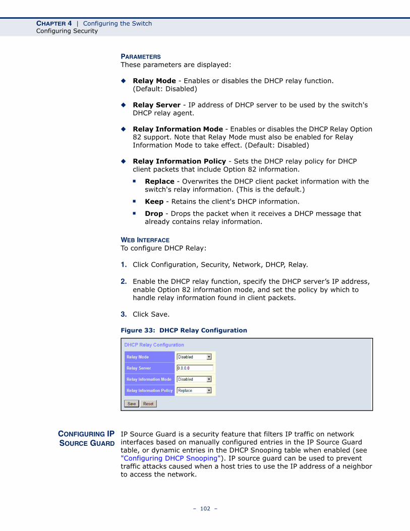
CHAPTER 4 | Configuring the SwitchConfiguring Security
PARAMETERSThese parameters are displayed:
◆ Relay Mode - Enables or disables the DHCP relay function. (Default: Disabled)
◆ Relay Server - IP address of DHCP server to be used by the switch's DHCP relay agent.
◆ Relay Information Mode - Enables or disables the DHCP Relay Option 82 support. Note that Relay Mode must also be enabled for Relay Information Mode to take effect. (Default: Disabled)
◆ Relay Information Policy - Sets the DHCP relay policy for DHCP client packets that include Option 82 information.
■ Replace - Overwrites the DHCP client packet information with the switch's relay information. (This is the default.)
■ Keep - Retains the client's DHCP information.
■ Drop - Drops the packet when it receives a DHCP message that already contains relay information.
WEB INTERFACETo configure DHCP Relay:
1. Click Configuration, Security, Network, DHCP, Relay.
2. Enable the DHCP relay function, specify the DHCP server’s IP address, enable Option 82 information mode, and set the policy by which to handle relay information found in client packets.
3. Click Save.
Figure 33: DHCP Relay Configuration
CONFIGURING IPSOURCE GUARD
IP Source Guard is a security feature that filters IP traffic on network interfaces based on manually configured entries in the IP Source Guard table, or dynamic entries in the DHCP Snooping table when enabled (see "Configuring DHCP Snooping"). IP source guard can be used to prevent traffic attacks caused when a host tries to use the IP address of a neighbor to access the network.
– 102 –
CHAPTER 4 | Configuring the SwitchConfiguring Security
CONFIGURING GLOBAL AND PORT SETTINGS FOR IP SOURCE GUARD
Use the IP Source Guard Configuration page to filter traffic on an insecure port which receives messages from outside the network or fire wall, and therefore may be subject to traffic attacks caused by a host trying to use the IP address of a neighbor. IP Source Guard filters traffic type based on the source IP address and MAC address pairs found in the DHCP Snooping table, or based upon static entries configured in the IP Source Guard Table.
PATH Configuration, Security, Network, IP Source Guard, Configuration
COMMAND USAGE◆ When IP Source Guard is enabled globally and on a port, the switch
checks the VLAN ID, source IP address, and port number against all entries in the DHCP Snooping binding table and IP Source Guard Static Table. If no matching entry is found, the packet is dropped.
NOTE: Multicast addresses cannot be used by IP Source Guard.
◆ When enabled, traffic is filtered based upon dynamic entries learned via DHCP snooping (see "Configuring DHCP Snooping"), or static addresses configured in the source guard binding table.
◆ If IP source guard is enabled, an inbound packet’s IP address will be checked against the binding table. If no matching entry is found, the packet will be dropped.
◆ Filtering rules are implemented as follows:
■ If DHCP snooping is disabled (see page 98), IP source guard will check the VLAN ID, source IP address, and port number. If a matching entry is found in the binding table and the entry type is static IP source guard binding, the packet will be forwarded.
■ If DHCP snooping is enabled, IP source guard will check the VLAN ID, source IP address, and port number. If a matching entry is found in the binding table and the entry type is static IP source guard binding, or dynamic DHCP snooping binding, the packet will be forwarded.
■ If IP source guard if enabled on an interface for which IP source bindings have not yet been configured (neither by static configuration in the IP source guard binding table nor dynamically learned from DHCP snooping), the switch will drop all IP traffic on that port, except for DHCP packets.
PARAMETERSThese parameters are displayed:
◆ Global Mode – Enables or disables IP Source Guard globally on the switch. All configured ACEs will be lost when enabled. (Default: Disabled)
– 103 –
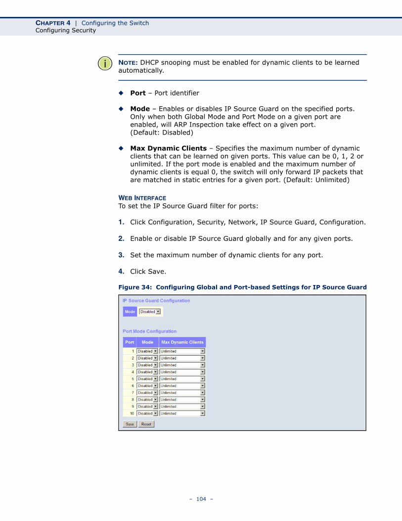
CHAPTER 4 | Configuring the SwitchConfiguring Security
NOTE: DHCP snooping must be enabled for dynamic clients to be learned automatically.
◆ Port – Port identifier
◆ Mode – Enables or disables IP Source Guard on the specified ports. Only when both Global Mode and Port Mode on a given port are enabled, will ARP Inspection take effect on a given port. (Default: Disabled)
◆ Max Dynamic Clients – Specifies the maximum number of dynamic clients that can be learned on given ports. This value can be 0, 1, 2 or unlimited. If the port mode is enabled and the maximum number of dynamic clients is equal 0, the switch will only forward IP packets that are matched in static entries for a given port. (Default: Unlimited)
WEB INTERFACETo set the IP Source Guard filter for ports:
1. Click Configuration, Security, Network, IP Source Guard, Configuration.
2. Enable or disable IP Source Guard globally and for any given ports.
3. Set the maximum number of dynamic clients for any port.
4. Click Save.
Figure 34: Configuring Global and Port-based Settings for IP Source Guard
– 104 –
CHAPTER 4 | Configuring the SwitchConfiguring Security
CONFIGURING STATIC BINDINGS FOR IP SOURCE GUARD
Use the Static IP Source Guard Table to bind a static address to a port. Table entries include a port identifier, VLAN identifier, IP address, and subnet mask. All static entries are configured with an infinite lease time.
PATH Configuration, Security, Network, IP Source Guard, Static Table
COMMAND USAGE◆ Static addresses entered in the source guard binding table are
automatically configured with an infinite lease time. Dynamic entries learned via DHCP snooping are configured by the DHCP server itself.
◆ Static bindings are processed as follows:
■ If there is no entry with the same VLAN ID and MAC address, a new entry is added to the static IP source guard binding table.
■ If there is an entry with the same VLAN ID and MAC address, and the type of entry is static IP source guard binding, then the new entry will replace the old one.
■ If there is an entry with the same VLAN ID and MAC address, and the type of the entry is dynamic DHCP snooping binding, then the new entry will replace the old one and the entry type will be changed to static IP source guard binding.
■ Only unicast addresses are accepted for static bindings.
PARAMETERSThese parameters are displayed:
◆ Port – The port to which a static entry is bound.
◆ VLAN ID – ID of a configured VLAN (Range: 1-4095)
◆ IP Address – A valid unicast IP address, including classful types A, B or C.
◆ MAC Address – A valid unicast MAC address.
WEB INTERFACETo configure static bindings for IP Source Guard:
1. Click Configuration, Security, Network, IP Source Guard, Static Table.
2. Click “Add new entry.”
3. Enter the required bindings for a given port.
4. Click Save.
– 105 –
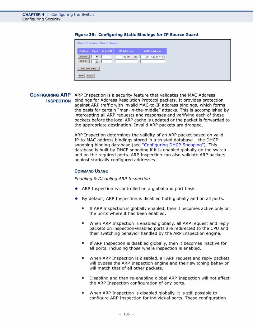
CHAPTER 4 | Configuring the SwitchConfiguring Security
Figure 35: Configuring Static Bindings for IP Source Guard
CONFIGURING ARPINSPECTION
ARP Inspection is a security feature that validates the MAC Address bindings for Address Resolution Protocol packets. It provides protection against ARP traffic with invalid MAC-to-IP address bindings, which forms the basis for certain “man-in-the-middle” attacks. This is accomplished by intercepting all ARP requests and responses and verifying each of these packets before the local ARP cache is updated or the packet is forwarded to the appropriate destination. Invalid ARP packets are dropped.
ARP Inspection determines the validity of an ARP packet based on valid IP-to-MAC address bindings stored in a trusted database – the DHCP snooping binding database (see "Configuring DHCP Snooping"). This database is built by DHCP snooping if it is enabled globally on the switch and on the required ports. ARP Inspection can also validate ARP packets against statically configured addresses.
COMMAND USAGE
Enabling & Disabling ARP Inspection
◆ ARP Inspection is controlled on a global and port basis.
◆ By default, ARP Inspection is disabled both globally and on all ports.
■ If ARP Inspection is globally enabled, then it becomes active only on the ports where it has been enabled.
■ When ARP Inspection is enabled globally, all ARP request and reply packets on inspection-enabled ports are redirected to the CPU and their switching behavior handled by the ARP Inspection engine.
■ If ARP Inspection is disabled globally, then it becomes inactive for all ports, including those where inspection is enabled.
■ When ARP Inspection is disabled, all ARP request and reply packets will bypass the ARP Inspection engine and their switching behavior will match that of all other packets.
■ Disabling and then re-enabling global ARP Inspection will not affect the ARP Inspection configuration of any ports.
■ When ARP Inspection is disabled globally, it is still possible to configure ARP Inspection for individual ports. These configuration
– 106 –
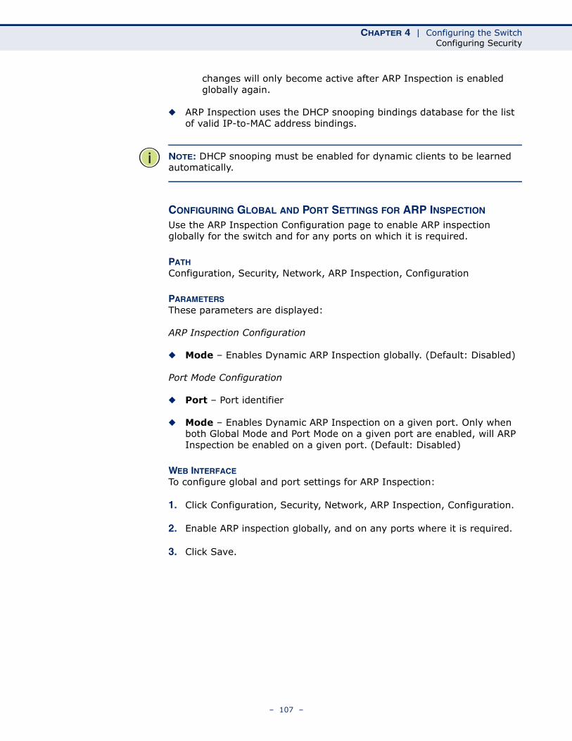
CHAPTER 4 | Configuring the SwitchConfiguring Security
changes will only become active after ARP Inspection is enabled globally again.
◆ ARP Inspection uses the DHCP snooping bindings database for the list of valid IP-to-MAC address bindings.
NOTE: DHCP snooping must be enabled for dynamic clients to be learned automatically.
CONFIGURING GLOBAL AND PORT SETTINGS FOR ARP INSPECTION
Use the ARP Inspection Configuration page to enable ARP inspection globally for the switch and for any ports on which it is required.
PATH Configuration, Security, Network, ARP Inspection, Configuration
PARAMETERSThese parameters are displayed:
ARP Inspection Configuration
◆ Mode – Enables Dynamic ARP Inspection globally. (Default: Disabled)
Port Mode Configuration
◆ Port – Port identifier
◆ Mode – Enables Dynamic ARP Inspection on a given port. Only when both Global Mode and Port Mode on a given port are enabled, will ARP Inspection be enabled on a given port. (Default: Disabled)
WEB INTERFACETo configure global and port settings for ARP Inspection:
1. Click Configuration, Security, Network, ARP Inspection, Configuration.
2. Enable ARP inspection globally, and on any ports where it is required.
3. Click Save.
– 107 –
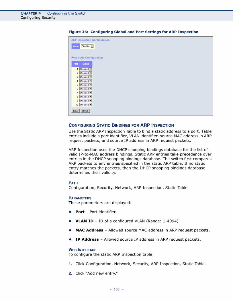
CHAPTER 4 | Configuring the SwitchConfiguring Security
Figure 36: Configuring Global and Port Settings for ARP Inspection
CONFIGURING STATIC BINDINGS FOR ARP INSPECTION
Use the Static ARP Inspection Table to bind a static address to a port. Table entries include a port identifier, VLAN identifier, source MAC address in ARP request packets, and source IP address in ARP request packets.
ARP Inspection uses the DHCP snooping bindings database for the list of valid IP-to-MAC address bindings. Static ARP entries take precedence over entries in the DHCP snooping bindings database. The switch first compares ARP packets to any entries specified in the static ARP table. If no static entry matches the packets, then the DHCP snooping bindings database determines their validity.
PATH Configuration, Security, Network, ARP Inspection, Static Table
PARAMETERSThese parameters are displayed:
◆ Port – Port identifier.
◆ VLAN ID – ID of a configured VLAN (Range: 1-4094)
◆ MAC Address – Allowed source MAC address in ARP request packets.
◆ IP Address – Allowed source IP address in ARP request packets.
WEB INTERFACETo configure the static ARP Inspection table:
1. Click Configuration, Network, Security, ARP Inspection, Static Table.
2. Click “Add new entry.”
– 108 –
CHAPTER 4 | Configuring the SwitchConfiguring Security
3. Enter the required bindings for a given port.
4. Click Save.
Figure 37: Configuring Static Bindings for ARP Inspection
SPECIFYINGAUTHENTICATION
SERVERS
Use the Authentication Server Configuration page to control management access based on a list of user names and passwords configured on a RADIUS or TACACS+ remote access authentication server, and to authenticate client access for IEEE 802.1X port authentication (see page 77)
NOTE: This guide assumes that RADIUS and TACACS+ servers have already been configured to support AAA. The configuration of RADIUS and TACACS+ server software is beyond the scope of this guide. Refer to the documentation provided with the RADIUS and TACACS+ server software.
PATH Configuration, Security, Network, AAA
PARAMETERSThese parameters are displayed:
Common Server Configuration
◆ Timeout – The time the switch waits for a reply from an authentication server before it resends the request. (Range: 3-3600 seconds; Default: 15 seconds)
◆ Dead Time – The time after which the switch considers an authentication server to be dead if it does not reply. (Range: 0-3600 seconds; Default: 300 seconds)
Setting the Dead Time to a value greater than 0 (zero) will cause the authentication server to be ignored until the Dead Time has expired. However, if only one server is enabled, it will never be considered dead.
RADIUS/TACACS+ Server Configuration
◆ Enabled – Enables the server specified in this entry.
◆ IP Address – IP address or IP alias of authentication server.
– 109 –
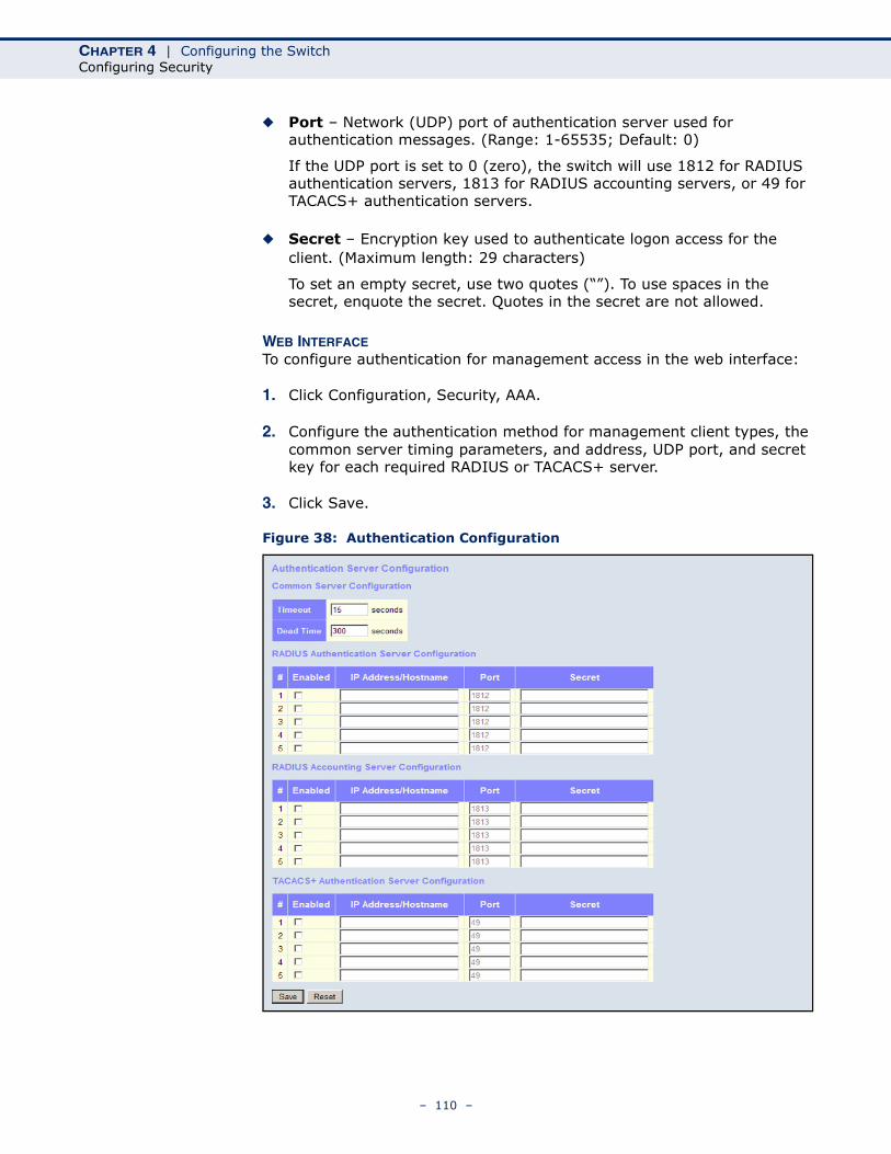
CHAPTER 4 | Configuring the SwitchConfiguring Security
◆ Port – Network (UDP) port of authentication server used for authentication messages. (Range: 1-65535; Default: 0)
If the UDP port is set to 0 (zero), the switch will use 1812 for RADIUS authentication servers, 1813 for RADIUS accounting servers, or 49 for TACACS+ authentication servers.
◆ Secret – Encryption key used to authenticate logon access for the client. (Maximum length: 29 characters)
To set an empty secret, use two quotes (“”). To use spaces in the secret, enquote the secret. Quotes in the secret are not allowed.
WEB INTERFACETo configure authentication for management access in the web interface:
1. Click Configuration, Security, AAA.
2. Configure the authentication method for management client types, the common server timing parameters, and address, UDP port, and secret key for each required RADIUS or TACACS+ server.
3. Click Save.
Figure 38: Authentication Configuration
– 110 –
CHAPTER 4 | Configuring the SwitchCreating Trunk Groups
CREATING TRUNK GROUPS You can create multiple links between devices that work as one virtual, aggregate link. A port trunk offers a dramatic increase in bandwidth for network segments where bottlenecks exist, as well as providing a fault-tolerant link between two switches.
The switch supports both static trunking and dynamic Link Aggregation Control Protocol (LACP). Static trunks have to be manually configured at both ends of the link, and the switches must comply with the Cisco EtherChannel standard. On the other hand, LACP configured ports can automatically negotiate a trunked link with LACP-configured ports on another device. You can configure any number of ports on the switch to use LACP, as long as they are not already configured as part of a static trunk. If ports on another device are also configured to use LACP, the switch and the other device will negotiate a trunk between them. If an LACP trunk consists of more than eight ports, all other ports will be placed in standby mode. Should one link in the trunk fail, one of the standby ports will automatically be activated to replace it.
USAGE GUIDELINESBesides balancing the load across each port in the trunk, the other ports provide redundancy by taking over the load if a port in the trunk fails. However, before making any physical connections between devices, configure the trunk on the devices at both ends. When using a port trunk, take note of the following points:
◆ Finish configuring port trunks before you connect the corresponding network cables between switches to avoid creating a loop.
◆ You can create up to 14 trunks on a switch, with up to 16 ports per trunk.
◆ The ports at both ends of a connection must be configured as trunk ports.
◆ When configuring static trunks on switches of different types, they must be compatible with the Cisco EtherChannel standard.
◆ The ports at both ends of a trunk must be configured in an identical manner, including communication mode (i.e., speed, duplex mode and flow control), VLAN assignments, and CoS settings.
◆ Any of the Gigabit ports on the front panel can be trunked together, including ports of different media types.
◆ All the ports in a trunk have to be treated as a whole when moved from/to, added or deleted from a VLAN.
◆ STP, VLAN, and IGMP settings can only be made for the entire trunk.
– 111 –
CHAPTER 4 | Configuring the SwitchCreating Trunk Groups
CONFIGURING STATICTRUNKS
Use the Aggregation Mode Configuration page to configure the aggregation mode and members of each static trunk group.
PATH Configuration, Aggregation, Static
USAGE GUIDELINES◆ When configuring static trunks, you may not be able to link switches of
different types, depending on the manufacturer's implementation. However, note that the static trunks on this switch are Cisco EtherChannel compatible.
◆ To avoid creating a loop in the network, be sure you add a static trunk via the configuration interface before connecting the ports, and also disconnect the ports before removing a static trunk via the configuration interface.
◆ When incoming data frames are forwarded through the switch to a trunk, the switch must determine to which port link in the trunk an outgoing frame should be sent. To maintain the frame sequence of various traffic flows between devices in the network, the switch also needs to ensure that frames in each “conversation” are mapped to the same trunk link. To achieve this requirement and to distribute a balanced load across all links in a trunk, the switch uses a hash algorithm to calculate an output link number in the trunk. However, depending on the device to which a trunk is connected and the traffic flows in the network, this load-balance algorithm may result in traffic being distributed mostly on one port in a trunk. To ensure that the switch traffic load is distributed evenly across all links in a trunk, the hash method used in the load-balance calculation can be selected to provide the best result for trunk connections. The switch provides four load-balancing modes as described in the following section.
◆ Aggregation Mode Configuration also applies to LACP (see "Configuring LACP" on page 114).
PARAMETERSThese parameters are displayed:
Aggregation Mode Configuration
◆ Hash Code Contributors – Selects the load-balance method to apply to all trunks on the switch. If more than one option is selected, each factor is used in the hash algorithm to determine the port member within the trunk to which a frame will be assigned. The following options are supported:
■ Source MAC Address – All traffic with the same source MAC address is output on the same link in a trunk. This mode works best for switch-to-switch trunk links where traffic through the switch is received from many different hosts. (One of the defaults.)
– 112 –
CHAPTER 4 | Configuring the SwitchCreating Trunk Groups
■ Destination MAC Address – All traffic with the same destination MAC address is output on the same link in a trunk. This mode works best for switch-to-switch trunk links where traffic through the switch is destined for many different hosts. Do not use this mode for switch-to-router trunk links where the destination MAC address is the same for all traffic.
■ IP Address – All traffic with the same source and destination IP address is output on the same link in a trunk. This mode works best for switch-to-router trunk links where traffic through the switch is destined for many different hosts. Do not use this mode for switch-to-server trunk links where the destination IP address is the same for all traffic. (One of the defaults.)
■ TCP/UDP Port Number – All traffic with the same source and destination TCP/UDP port number is output on the same link in a trunk. Avoid using his mode as a lone option. It may overload a single port member of the trunk for application traffic of a specific type, such as web browsing. However, it can be used effectively in combination with the IP Address option. (One of the defaults.)
Aggregation Group Configuration
◆ Group ID – Trunk identifier. (Range: 1-5)
◆ Port Members – Port identifier.
WEB INTERFACETo configure a static trunk:
1. Click Configuration, Aggregation, Static.
2. Select one or more load-balancing methods to apply to the configured trunks.
3. Assign port members to each trunk that will be used.
4. Click Save.
– 113 –
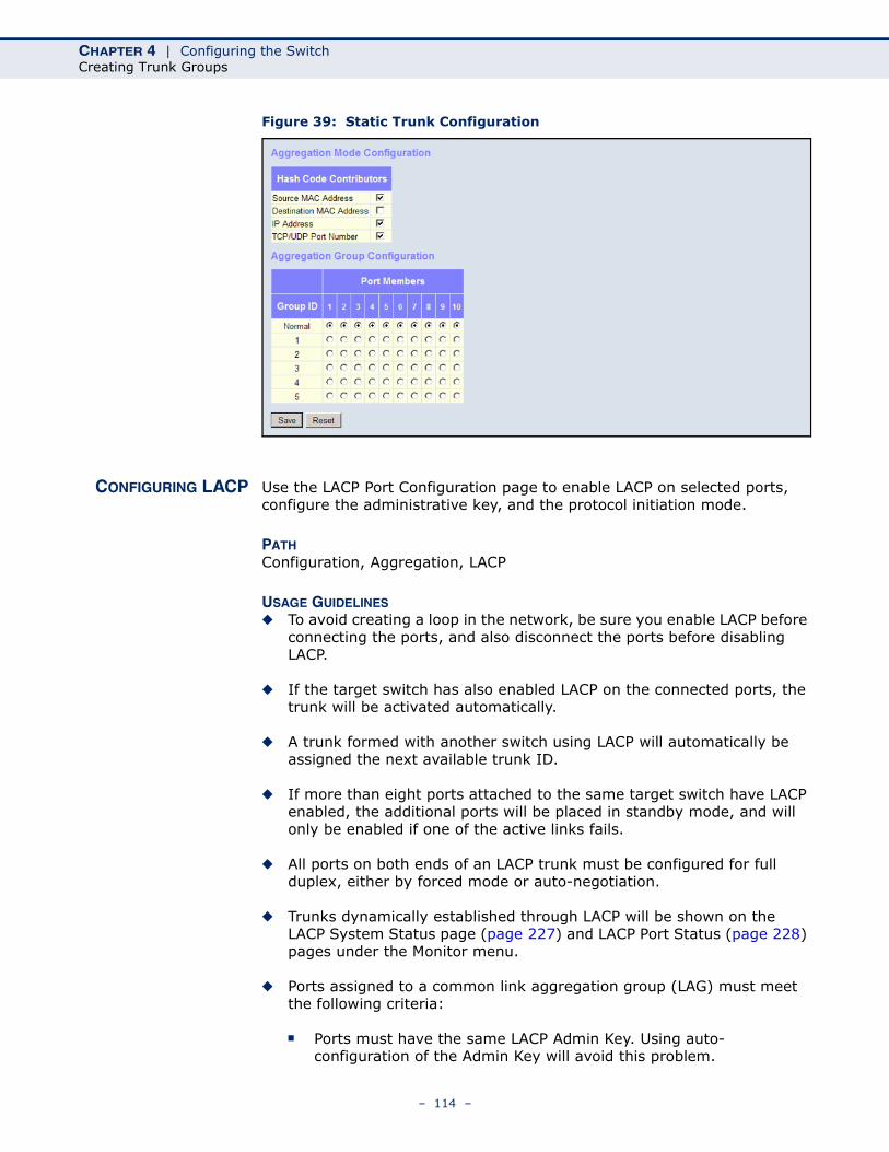
CHAPTER 4 | Configuring the SwitchCreating Trunk Groups
Figure 39: Static Trunk Configuration
CONFIGURING LACP Use the LACP Port Configuration page to enable LACP on selected ports, configure the administrative key, and the protocol initiation mode.
PATH Configuration, Aggregation, LACP
USAGE GUIDELINES◆ To avoid creating a loop in the network, be sure you enable LACP before
connecting the ports, and also disconnect the ports before disabling LACP.
◆ If the target switch has also enabled LACP on the connected ports, the trunk will be activated automatically.
◆ A trunk formed with another switch using LACP will automatically be assigned the next available trunk ID.
◆ If more than eight ports attached to the same target switch have LACP enabled, the additional ports will be placed in standby mode, and will only be enabled if one of the active links fails.
◆ All ports on both ends of an LACP trunk must be configured for full duplex, either by forced mode or auto-negotiation.
◆ Trunks dynamically established through LACP will be shown on the LACP System Status page (page 227) and LACP Port Status (page 228) pages under the Monitor menu.
◆ Ports assigned to a common link aggregation group (LAG) must meet the following criteria:
■ Ports must have the same LACP Admin Key. Using auto-configuration of the Admin Key will avoid this problem.
– 114 –
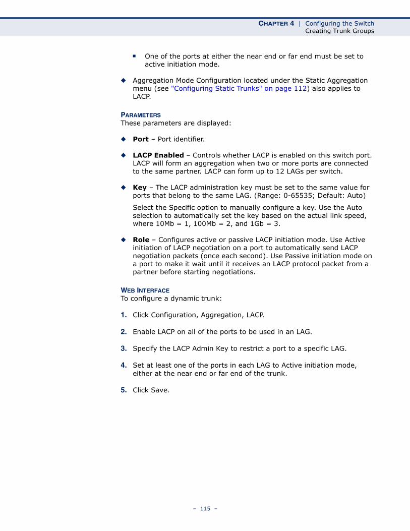
CHAPTER 4 | Configuring the SwitchCreating Trunk Groups
■ One of the ports at either the near end or far end must be set to active initiation mode.
◆ Aggregation Mode Configuration located under the Static Aggregation menu (see "Configuring Static Trunks" on page 112) also applies to LACP.
PARAMETERSThese parameters are displayed:
◆ Port – Port identifier.
◆ LACP Enabled – Controls whether LACP is enabled on this switch port. LACP will form an aggregation when two or more ports are connected to the same partner. LACP can form up to 12 LAGs per switch.
◆ Key – The LACP administration key must be set to the same value for ports that belong to the same LAG. (Range: 0-65535; Default: Auto)
Select the Specific option to manually configure a key. Use the Auto selection to automatically set the key based on the actual link speed, where 10Mb = 1, 100Mb = 2, and 1Gb = 3.
◆ Role – Configures active or passive LACP initiation mode. Use Active initiation of LACP negotiation on a port to automatically send LACP negotiation packets (once each second). Use Passive initiation mode on a port to make it wait until it receives an LACP protocol packet from a partner before starting negotiations.
WEB INTERFACETo configure a dynamic trunk:
1. Click Configuration, Aggregation, LACP.
2. Enable LACP on all of the ports to be used in an LAG.
3. Specify the LACP Admin Key to restrict a port to a specific LAG.
4. Set at least one of the ports in each LAG to Active initiation mode, either at the near end or far end of the trunk.
5. Click Save.
– 115 –
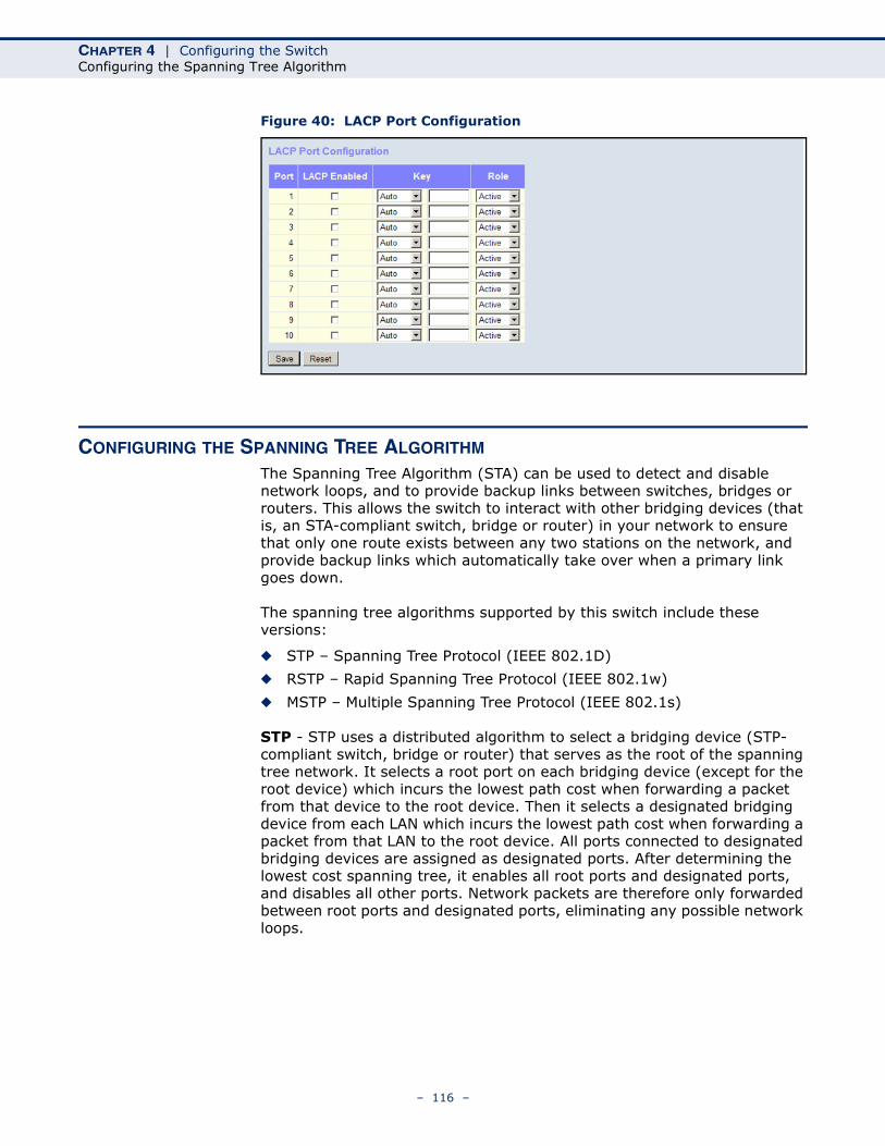
CHAPTER 4 | Configuring the SwitchConfiguring the Spanning Tree Algorithm
Figure 40: LACP Port Configuration
CONFIGURING THE SPANNING TREE ALGORITHM
The Spanning Tree Algorithm (STA) can be used to detect and disable network loops, and to provide backup links between switches, bridges or routers. This allows the switch to interact with other bridging devices (that is, an STA-compliant switch, bridge or router) in your network to ensure that only one route exists between any two stations on the network, and provide backup links which automatically take over when a primary link goes down.
The spanning tree algorithms supported by this switch include these versions:
◆ STP – Spanning Tree Protocol (IEEE 802.1D)
◆ RSTP – Rapid Spanning Tree Protocol (IEEE 802.1w)
◆ MSTP – Multiple Spanning Tree Protocol (IEEE 802.1s)
STP - STP uses a distributed algorithm to select a bridging device (STP-compliant switch, bridge or router) that serves as the root of the spanning tree network. It selects a root port on each bridging device (except for the root device) which incurs the lowest path cost when forwarding a packet from that device to the root device. Then it selects a designated bridging device from each LAN which incurs the lowest path cost when forwarding a packet from that LAN to the root device. All ports connected to designated bridging devices are assigned as designated ports. After determining the lowest cost spanning tree, it enables all root ports and designated ports, and disables all other ports. Network packets are therefore only forwarded between root ports and designated ports, eliminating any possible network loops.
– 116 –
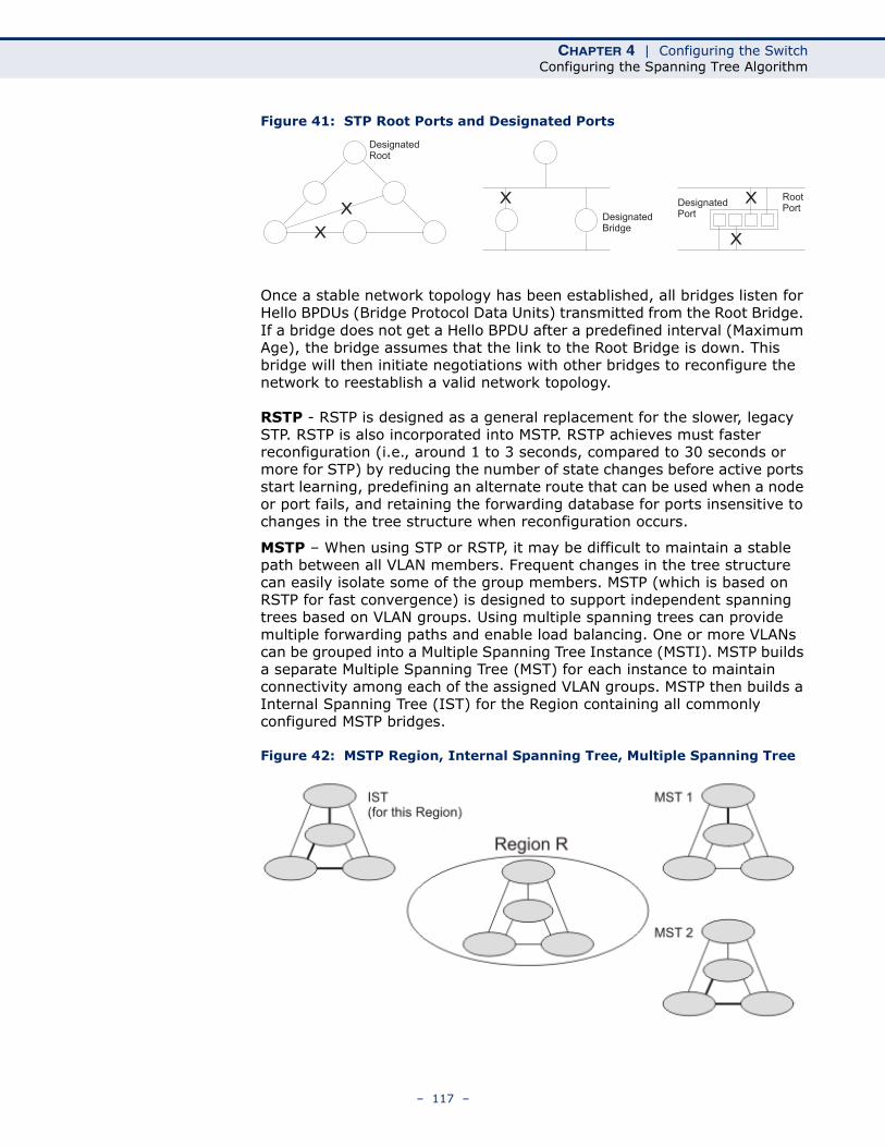
CHAPTER 4 | Configuring the SwitchConfiguring the Spanning Tree Algorithm
Figure 41: STP Root Ports and Designated Ports
Once a stable network topology has been established, all bridges listen for Hello BPDUs (Bridge Protocol Data Units) transmitted from the Root Bridge. If a bridge does not get a Hello BPDU after a predefined interval (Maximum Age), the bridge assumes that the link to the Root Bridge is down. This bridge will then initiate negotiations with other bridges to reconfigure the network to reestablish a valid network topology.
RSTP - RSTP is designed as a general replacement for the slower, legacy STP. RSTP is also incorporated into MSTP. RSTP achieves must faster reconfiguration (i.e., around 1 to 3 seconds, compared to 30 seconds or more for STP) by reducing the number of state changes before active ports start learning, predefining an alternate route that can be used when a node or port fails, and retaining the forwarding database for ports insensitive to changes in the tree structure when reconfiguration occurs.
MSTP – When using STP or RSTP, it may be difficult to maintain a stable path between all VLAN members. Frequent changes in the tree structure can easily isolate some of the group members. MSTP (which is based on RSTP for fast convergence) is designed to support independent spanning trees based on VLAN groups. Using multiple spanning trees can provide multiple forwarding paths and enable load balancing. One or more VLANs can be grouped into a Multiple Spanning Tree Instance (MSTI). MSTP builds a separate Multiple Spanning Tree (MST) for each instance to maintain connectivity among each of the assigned VLAN groups. MSTP then builds a Internal Spanning Tree (IST) for the Region containing all commonly configured MSTP bridges.
Figure 42: MSTP Region, Internal Spanning Tree, Multiple Spanning Tree
x
DesignatedRoot
DesignatedPortDesignated
Bridge
x x
x
RootPort
x
– 117 –
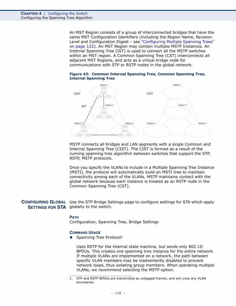
CHAPTER 4 | Configuring the SwitchConfiguring the Spanning Tree Algorithm
An MST Region consists of a group of interconnected bridges that have the same MST Configuration Identifiers (including the Region Name, Revision Level and Configuration Digest – see "Configuring Multiple Spanning Trees" on page 122). An MST Region may contain multiple MSTP Instances. An Internal Spanning Tree (IST) is used to connect all the MSTP switches within an MST region. A Common Spanning Tree (CST) interconnects all adjacent MST Regions, and acts as a virtual bridge node for communications with STP or RSTP nodes in the global network.
Figure 43: Common Internal Spanning Tree, Common Spanning Tree, Internal Spanning Tree
MSTP connects all bridges and LAN segments with a single Common and Internal Spanning Tree (CIST). The CIST is formed as a result of the running spanning tree algorithm between switches that support the STP, RSTP, MSTP protocols.
Once you specify the VLANs to include in a Multiple Spanning Tree Instance (MSTI), the protocol will automatically build an MSTI tree to maintain connectivity among each of the VLANs. MSTP maintains contact with the global network because each instance is treated as an RSTP node in the Common Spanning Tree (CST).
CONFIGURING GLOBALSETTINGS FOR STA
Use the STP Bridge Settings page to configure settings for STA which apply globally to the switch.
PATH Configuration, Spanning Tree, Bridge Settings
COMMAND USAGE
◆ Spanning Tree Protocol1
Uses RSTP for the internal state machine, but sends only 802.1D BPDUs. This creates one spanning tree instance for the entire network. If multiple VLANs are implemented on a network, the path between specific VLAN members may be inadvertently disabled to prevent network loops, thus isolating group members. When operating multiple VLANs, we recommend selecting the MSTP option.
Region 1
Region 4
Region 2 Region 3
CIST
IST
Region 1
Region 4
Region 2 Region 3
CST
1. STP and RSTP BPDUs are transmitted as untagged frames, and will cross any VLAN boundaries.
– 118 –
CHAPTER 4 | Configuring the SwitchConfiguring the Spanning Tree Algorithm
◆ Rapid Spanning Tree Protocol1
RSTP supports connections to either STP or RSTP nodes by monitoring the incoming protocol messages and dynamically adjusting the type of protocol messages the RSTP node transmits, as described below:
■ STP Mode – If the switch receives an 802.1D BPDU (i.e., STP BPDU) after a port’s migration delay timer expires, the switch assumes it is connected to an 802.1D bridge and starts using only 802.1D BPDUs.
■ RSTP Mode – If RSTP is using 802.1D BPDUs on a port and receives an RSTP BPDU after the migration delay expires, RSTP restarts the migration delay timer and begins using RSTP BPDUs on that port.
◆ Multiple Spanning Tree Protocol
MSTP generates a unique spanning tree for each instance. This provides multiple pathways across the network, thereby balancing the traffic load, preventing wide-scale disruption when a bridge node in a single instance fails, and allowing for faster convergence of a new topology for the failed instance.
■ To allow multiple spanning trees to operate over the network, you must configure a related set of bridges with the same MSTP configuration, allowing them to participate in a specific set of spanning tree instances.
■ A spanning tree instance can exist only on bridges that have compatible VLAN instance assignments.
■ Be careful when switching between spanning tree modes. Changing modes stops all spanning-tree instances for the previous mode and restarts the system in the new mode, temporarily disrupting user traffic.
PARAMETERSThese parameters are displayed:
Basic Settings
◆ Protocol Version – Specifies the type of spanning tree used on this switch. (Options: STP, RSTP, MSTP; Default: MSTP)
■ STP: Spanning Tree Protocol (IEEE 802.1D); i.e., the switch will use RSTP set to STP forced compatibility mode.
■ RSTP: Rapid Spanning Tree (IEEE 802.1w)
■ MSTP: Multiple Spanning Tree (IEEE 802.1s); This is the default.
◆ Bridge Priority – Bridge priority is used in selecting the root device, root port, and designated port. The device with the highest priority becomes the STA root device. However, if all devices have the same
– 119 –
CHAPTER 4 | Configuring the SwitchConfiguring the Spanning Tree Algorithm
priority, the device with the lowest MAC address will then become the root device. (Note that lower numeric values indicate higher priority.)
■ Default: 128■ Range: 0-240, in steps of 16■ Options: 0, 16, 32, 48, 64, 80, 96, 112, 128, 144, 160, 176, 192,
208, 224, 240
◆ Forward Delay – The maximum time (in seconds) this device will wait before changing states (i.e., discarding to learning to forwarding). This delay is required because every device must receive information about topology changes before it starts to forward frames. In addition, each port needs time to listen for conflicting information that would make it return to a discarding state; otherwise, temporary data loops might result.
Minimum: The higher of 4 or [(Max. Message Age / 2) + 1]Maximum: 30Default: 15
◆ Max Age – The maximum time (in seconds) a device can wait without receiving a configuration message before attempting to reconfigure. All device ports (except for designated ports) should receive configuration messages at regular intervals. Any port that ages out STA information (provided in the last configuration message) becomes the designated port for the attached LAN. If it is a root port, a new root port is selected from among the device ports attached to the network. (Note that references to “ports” in this section mean “interfaces,” which includes both ports and trunks.)
Minimum: The higher of 6 or [2 x (Hello Time + 1)]Maximum: The lower of 40 or [2 x (Forward Delay - 1)]Default: 20
◆ Transmit Hold Count – The number of BPDU's a bridge port can send per second. When exceeded, transmission of the next BPDU will be delayed. (Range: 1-10; Default: 6)
◆ Max Hop Count – The maximum number of hops allowed in the MST region before a BPDU is discarded. (Range: 6-40; Default: 20)
An MST region is treated as a single node by the STP and RSTP protocols. Therefore, the message age for BPDUs inside an MST region is never changed. However, each spanning tree instance within a region, and the common internal spanning tree (CIST) that connects these instances use a hop count to specify the maximum number of bridges that will propagate a BPDU. Each bridge decrements the hop count by one before passing on the BPDU. When the hop count reaches zero, the message is dropped.
Advanced Settings
◆ Edge Port BPDU Filtering – BPDU filtering allows you to avoid transmitting BPDUs on configured edge ports that are connected to end nodes. By default, STA sends BPDUs to all ports regardless of whether
– 120 –
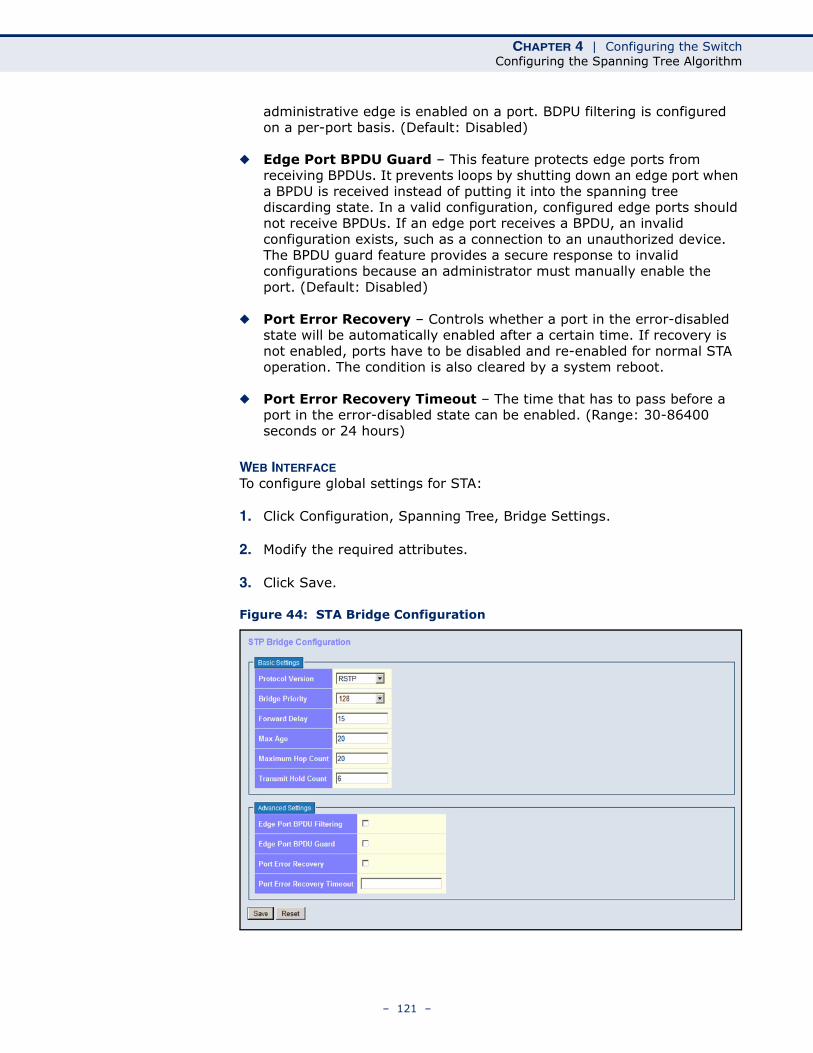
CHAPTER 4 | Configuring the SwitchConfiguring the Spanning Tree Algorithm
administrative edge is enabled on a port. BDPU filtering is configured on a per-port basis. (Default: Disabled)
◆ Edge Port BPDU Guard – This feature protects edge ports from receiving BPDUs. It prevents loops by shutting down an edge port when a BPDU is received instead of putting it into the spanning tree discarding state. In a valid configuration, configured edge ports should not receive BPDUs. If an edge port receives a BPDU, an invalid configuration exists, such as a connection to an unauthorized device. The BPDU guard feature provides a secure response to invalid configurations because an administrator must manually enable the port. (Default: Disabled)
◆ Port Error Recovery – Controls whether a port in the error-disabled state will be automatically enabled after a certain time. If recovery is not enabled, ports have to be disabled and re-enabled for normal STA operation. The condition is also cleared by a system reboot.
◆ Port Error Recovery Timeout – The time that has to pass before a port in the error-disabled state can be enabled. (Range: 30-86400 seconds or 24 hours)
WEB INTERFACETo configure global settings for STA:
1. Click Configuration, Spanning Tree, Bridge Settings.
2. Modify the required attributes.
3. Click Save.
Figure 44: STA Bridge Configuration
– 121 –

CHAPTER 4 | Configuring the SwitchConfiguring the Spanning Tree Algorithm
CONFIGURINGMULTIPLE SPANNING
TREES
Use the MSTI Mapping page to add VLAN groups to an MSTP instance (MSTI), or to designate the name and revision of the VLAN-to-MSTI mapping used on this switch.
PATH Configuration, Spanning Tree, MSTI Mapping
COMMAND USAGEMSTP generates a unique spanning tree for each instance. This provides multiple pathways across the network, thereby balancing the traffic load, preventing wide-scale disruption when a bridge node in a single instance fails, and allowing for faster convergence of a new topology for the failed instance.
By default all VLANs are assigned to the Common Internal Spanning Tree (CIST, or MST Instance 0) that connects all bridges and LANs within the MST region. This switch supports up to 7 instances. You should try to group VLANs which cover the same general area of your network. However, remember that you must configure all bridges that exist within the same MSTI Region with the same set of instances, and the same instance (on each bridge) with the same set of VLANs. Also, note that RSTP treats each MSTI region as a single node, connecting all regions to the CIST.
To use multiple spanning trees:
1. Set the spanning tree type to MSTP (page 118).
2. Add the VLANs that will share this MSTI on the MSTI Mapping page.
3. Enter the spanning tree priority for the CIST and selected MST instance on the MSTI Priorities page.
NOTE: All VLANs are automatically added to the CIST (MST Instance 0).
To ensure that the MSTI maintains connectivity across the network, you must configure a related set of bridges with the same MSTI settings.
PARAMETERSThese parameters are displayed:
Configuration Identification
◆ Configuration Name2 – The name for this MSTI. (Maximum length: 32 characters; Default: switch’s MAC address)
◆ Configuration Revision2 – The revision for this MSTI. (Range: 0-65535; Default: 0)
2. The MST name and revision number are both required to uniquely identify an MST region.
– 122 –
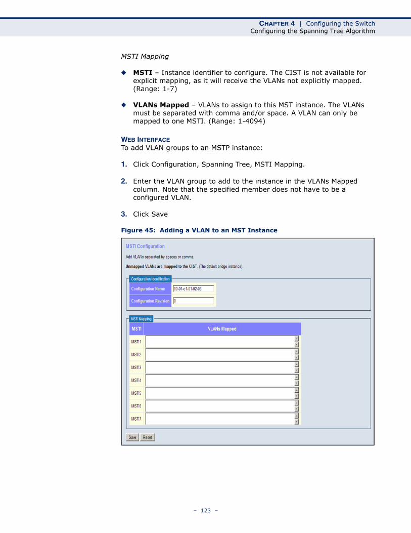
CHAPTER 4 | Configuring the SwitchConfiguring the Spanning Tree Algorithm
MSTI Mapping
◆ MSTI – Instance identifier to configure. The CIST is not available for explicit mapping, as it will receive the VLANs not explicitly mapped. (Range: 1-7)
◆ VLANs Mapped – VLANs to assign to this MST instance. The VLANs must be separated with comma and/or space. A VLAN can only be mapped to one MSTI. (Range: 1-4094)
WEB INTERFACETo add VLAN groups to an MSTP instance:
1. Click Configuration, Spanning Tree, MSTI Mapping.
2. Enter the VLAN group to add to the instance in the VLANs Mapped column. Note that the specified member does not have to be a configured VLAN.
3. Click Save
Figure 45: Adding a VLAN to an MST Instance
– 123 –
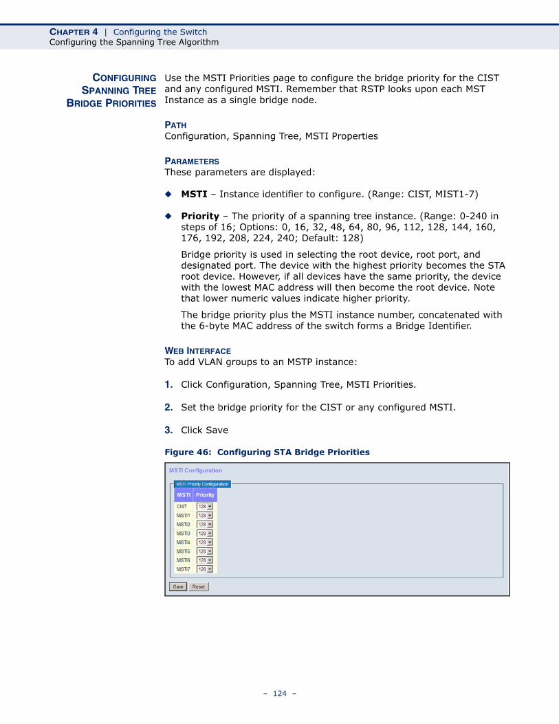
CHAPTER 4 | Configuring the SwitchConfiguring the Spanning Tree Algorithm
CONFIGURINGSPANNING TREE
BRIDGE PRIORITIES
Use the MSTI Priorities page to configure the bridge priority for the CIST and any configured MSTI. Remember that RSTP looks upon each MST Instance as a single bridge node.
PATH Configuration, Spanning Tree, MSTI Properties
PARAMETERSThese parameters are displayed:
◆ MSTI – Instance identifier to configure. (Range: CIST, MIST1-7)
◆ Priority – The priority of a spanning tree instance. (Range: 0-240 in steps of 16; Options: 0, 16, 32, 48, 64, 80, 96, 112, 128, 144, 160, 176, 192, 208, 224, 240; Default: 128)
Bridge priority is used in selecting the root device, root port, and designated port. The device with the highest priority becomes the STA root device. However, if all devices have the same priority, the device with the lowest MAC address will then become the root device. Note that lower numeric values indicate higher priority.
The bridge priority plus the MSTI instance number, concatenated with the 6-byte MAC address of the switch forms a Bridge Identifier.
WEB INTERFACETo add VLAN groups to an MSTP instance:
1. Click Configuration, Spanning Tree, MSTI Priorities.
2. Set the bridge priority for the CIST or any configured MSTI.
3. Click Save
Figure 46: Configuring STA Bridge Priorities
– 124 –
CHAPTER 4 | Configuring the SwitchConfiguring the Spanning Tree Algorithm
CONFIGURINGSTP/RSTP/CIST
INTERFACES
Use the CIST Ports Configuration page to configure STA attributes for interfaces when the spanning tree mode is set to STP or RSTP, or for interfaces in the CIST. STA interface attributes include path cost, port priority, edge port (for fast forwarding), automatic detection of an edge port, and point-to-point link type.
You may use a different priority or path cost for ports of the same media type to indicate the preferred path, edge port to indicate if the attached device can support fast forwarding, or link type to indicate a point-to-point connection or shared-media connection. (References to “ports” in this section means “interfaces,” which includes both ports and trunks.)
PATH Configuration, Spanning Tree, CIST Ports
PARAMETERSThese parameters are displayed:
◆ Port – Port identifier.
This field is not applicable to static trunks or dynamic trunks created through LACP. Also, note that only one set of interface configuration settings can be applied to all trunks.
◆ STP Enabled – Sets the interface to enable STA, disable STA, or disable STA with BPDU transparency. (Default: Enabled)
BPDU transparency is commonly used to support BPDU tunneling, passing BPDUs across a service provider’s network without any changes, thereby combining remote network segments into a single spanning tree. As implemented on this switch, BPDU transparency allows a port which is not participating in the spanning tree (such as an uplink port to the service provider’s network) to forward BPDU packets to other ports instead of discarding these packets or attempting to process them.
◆ Path Cost – This parameter is used by the STA to determine the best path between devices. Therefore, lower values should be assigned to ports attached to faster media, and higher values assigned to ports with slower media. (Path cost takes precedence over port priority.)
By default, the system automatically detects the speed and duplex mode used on each port, and configures the path cost according to the values shown below.
Table 9: Recommended STA Path Cost Range
Port Type IEEE 802.1D-1998 IEEE 802.1w-2001
Ethernet 50-600 200,000-20,000,000
Fast Ethernet 10-60 20,000-2,000,000
Gigabit Ethernet 3-10 2,000-200,000
– 125 –
CHAPTER 4 | Configuring the SwitchConfiguring the Spanning Tree Algorithm
◆ Priority – Defines the priority used for this port in the Spanning Tree Algorithm. If the path cost for all ports on a switch are the same, the port with the highest priority (i.e., lowest value) will be configured as an active link in the Spanning Tree. This makes a port with higher priority less likely to be blocked if the Spanning Tree Algorithm is detecting network loops. Where more than one port is assigned the highest priority, the port with lowest numeric identifier will be enabled. (Range: 0-240, in steps of 16; Default: 128)
◆ Admin Edge (Fast Forwarding) – You can enable this option if an interface is attached to a LAN segment that is at the end of a bridged LAN or to an end node. Since end nodes cannot cause forwarding loops, they can pass directly through to the spanning tree forwarding state. Specifying edge ports provides quicker convergence for devices such as workstations or servers, retains the current forwarding database to reduce the amount of frame flooding required to rebuild address tables during reconfiguration events, does not cause the spanning tree to initiate reconfiguration when the interface changes state, and also overcomes other STA-related timeout problems. However, remember that this feature should only be enabled for ports connected to an end-node device. (Default: Edge)
◆ Auto Edge – Controls whether automatic edge detection is enabled on a bridge port. When enabled, the bridge can determine that a port is at the edge of the network if no BPDU's are received on the port. (Default: Enabled)
◆ Restricted Role – If enabled, this causes the port not to be selected as Root Port for the CIST or any MSTI, even if it has the best spanning
Table 10: Recommended STA Path Costs
Port Type Link Type IEEE 802.1D-1998 IEEE 802.1w-2001
Ethernet Half DuplexFull DuplexTrunk
1009590
2,000,0001,999,9991,000,000
Fast Ethernet Half DuplexFull DuplexTrunk
191815
200,000100,00050,000
Gigabit Ethernet Full DuplexTrunk
43
10,0005,000
Table 11: Default STA Path Costs
Port Type Link Type IEEE 802.1w-2001
Ethernet Half DuplexFull DuplexTrunk
2,000,0001,000,000500,000
Fast Ethernet Half DuplexFull DuplexTrunk
200,000100,00050,000
Gigabit Ethernet Full DuplexTrunk
10,0005,000
– 126 –
CHAPTER 4 | Configuring the SwitchConfiguring the Spanning Tree Algorithm
tree priority. Such a port will be selected as an Alternate Port after the Root Port has been selected. If set, this can cause a lack of spanning tree connectivity. It can be set by a network administrator to prevent bridges external to a core region of the network influencing the spanning tree active topology, possibly because those bridges are not under the full control of the administrator. This feature is also know as Root Guard.
◆ Restricted TCN – If enabled, this causes the port not to propagate received topology change notifications and topology changes to other ports. TCN messages can cause temporary loss of connectivity after changes in a spanning tree’s active topology as a result of persistent incorrectly learned station location information. TCN messages can be restricted by a network administrator to prevent bridges external to a core region of the network from causing address flushing in that region, possibly because those bridges are not under the full control of the administrator or the physical link state for the attached LANs transitions frequently.
◆ BPDU Guard – This feature protects ports from receiving BPDUs. It can prevent loops by shutting down an port when a BPDU is received instead of putting it into the spanning tree discarding state. The BPDU guard feature provides a secure response to invalid configurations because an administrator must manually enable the port. (Default: Disabled)
If enabled, the port will disable itself upon receiving valid BPDU's. Contrary to the similar bridge setting, the port Edge status does not affect this setting. A port entering error-disabled state due to this setting is subject to the bridge Port Error Recovery setting as well (see "Configuring Global Settings for STA" on page 118).
◆ Point-to-Point – The link type attached to an interface can be set to automatically detect the link type, or manually configured as point-to-point or shared medium. Transition to the forwarding state is faster for point-to-point links than for shared media. These options are described below:
■ Auto – The switch automatically determines if the interface is attached to a point-to-point link or to shared medium. (This is the default setting.)
When automatic detection is selected, the switch derives the link type from the duplex mode. A full-duplex interface is considered a point-to-point link, while a half-duplex interface is assumed to be on a shared link.
■ Forced True – A point-to-point connection to exactly one other bridge.
■ Forced False – A shared connection to two or more bridges.
– 127 –
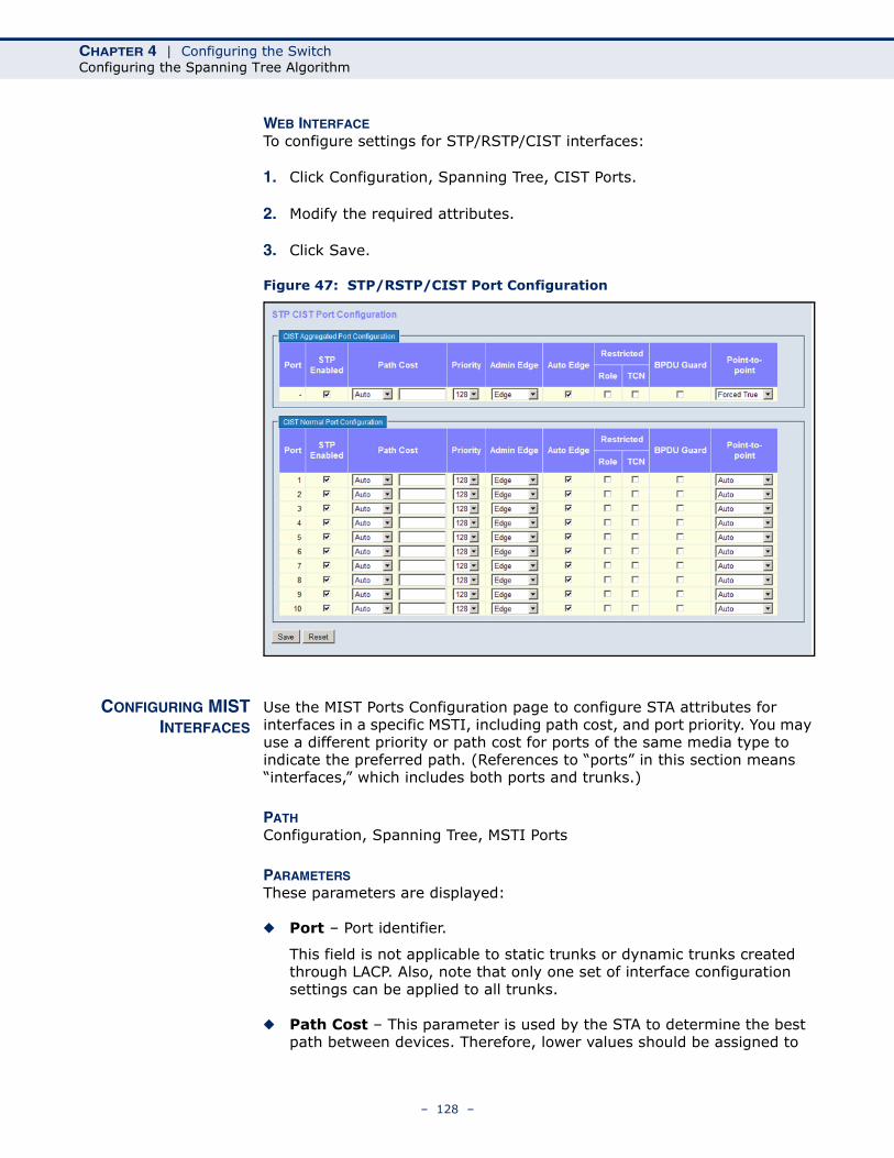
CHAPTER 4 | Configuring the SwitchConfiguring the Spanning Tree Algorithm
WEB INTERFACETo configure settings for STP/RSTP/CIST interfaces:
1. Click Configuration, Spanning Tree, CIST Ports.
2. Modify the required attributes.
3. Click Save.
Figure 47: STP/RSTP/CIST Port Configuration
CONFIGURING MISTINTERFACES
Use the MIST Ports Configuration page to configure STA attributes for interfaces in a specific MSTI, including path cost, and port priority. You may use a different priority or path cost for ports of the same media type to indicate the preferred path. (References to “ports” in this section means “interfaces,” which includes both ports and trunks.)
PATH Configuration, Spanning Tree, MSTI Ports
PARAMETERSThese parameters are displayed:
◆ Port – Port identifier.
This field is not applicable to static trunks or dynamic trunks created through LACP. Also, note that only one set of interface configuration settings can be applied to all trunks.
◆ Path Cost – This parameter is used by the STA to determine the best path between devices. Therefore, lower values should be assigned to
– 128 –
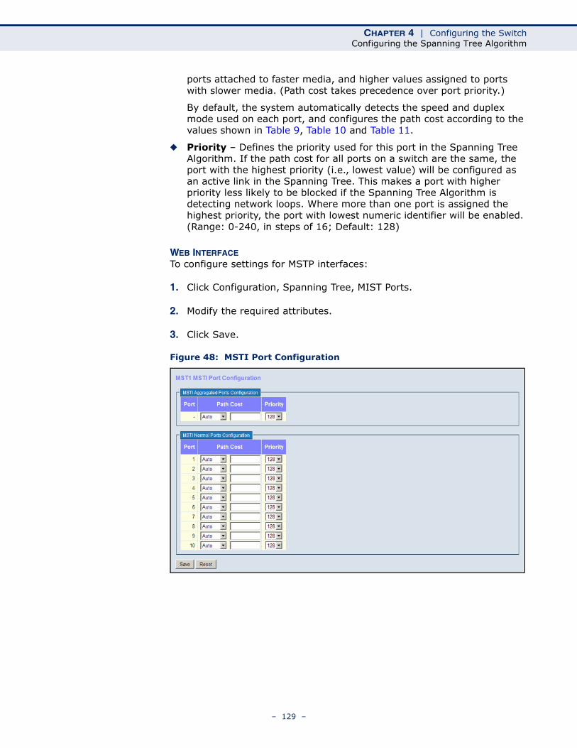
CHAPTER 4 | Configuring the SwitchConfiguring the Spanning Tree Algorithm
ports attached to faster media, and higher values assigned to ports with slower media. (Path cost takes precedence over port priority.)
By default, the system automatically detects the speed and duplex mode used on each port, and configures the path cost according to the values shown in Table 9, Table 10 and Table 11.
◆ Priority – Defines the priority used for this port in the Spanning Tree Algorithm. If the path cost for all ports on a switch are the same, the port with the highest priority (i.e., lowest value) will be configured as an active link in the Spanning Tree. This makes a port with higher priority less likely to be blocked if the Spanning Tree Algorithm is detecting network loops. Where more than one port is assigned the highest priority, the port with lowest numeric identifier will be enabled. (Range: 0-240, in steps of 16; Default: 128)
WEB INTERFACETo configure settings for MSTP interfaces:
1. Click Configuration, Spanning Tree, MIST Ports.
2. Modify the required attributes.
3. Click Save.
Figure 48: MSTI Port Configuration
– 129 –
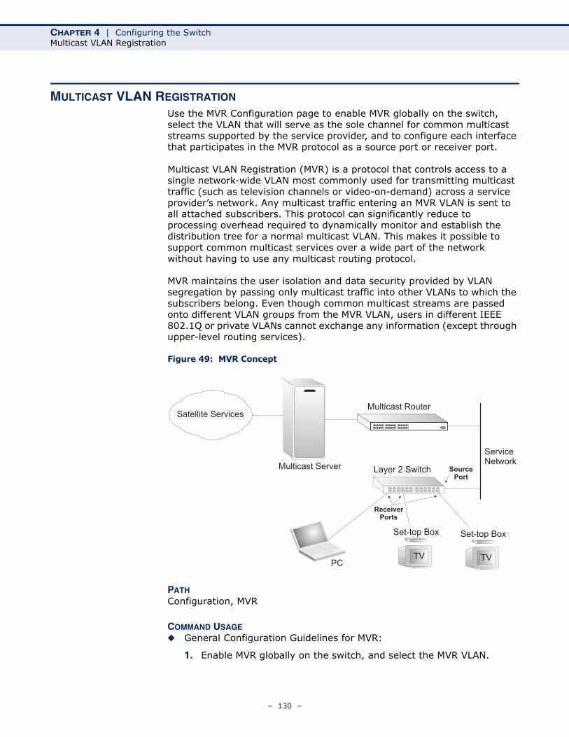
CHAPTER 4 | Configuring the SwitchMulticast VLAN Registration
MULTICAST VLAN REGISTRATION
Use the MVR Configuration page to enable MVR globally on the switch, select the VLAN that will serve as the sole channel for common multicast streams supported by the service provider, and to configure each interface that participates in the MVR protocol as a source port or receiver port.
Multicast VLAN Registration (MVR) is a protocol that controls access to a single network-wide VLAN most commonly used for transmitting multicast traffic (such as television channels or video-on-demand) across a service provider’s network. Any multicast traffic entering an MVR VLAN is sent to all attached subscribers. This protocol can significantly reduce to processing overhead required to dynamically monitor and establish the distribution tree for a normal multicast VLAN. This makes it possible to support common multicast services over a wide part of the network without having to use any multicast routing protocol.
MVR maintains the user isolation and data security provided by VLAN segregation by passing only multicast traffic into other VLANs to which the subscribers belong. Even though common multicast streams are passed onto different VLAN groups from the MVR VLAN, users in different IEEE 802.1Q or private VLANs cannot exchange any information (except through upper-level routing services).
Figure 49: MVR Concept
PATH Configuration, MVR
COMMAND USAGE◆ General Configuration Guidelines for MVR:
1. Enable MVR globally on the switch, and select the MVR VLAN.
Multicast Router
Layer 2 SwitchMulticast Server
PCTV
Set-top Box
TV
Set-top Box
Satellite Services
ServiceNetwork
Source
Port
Receiver
Ports
– 130 –
CHAPTER 4 | Configuring the SwitchMulticast VLAN Registration
2. Set the interfaces that will join the MVR as source ports or receiver ports.
3. If you are sure that only one subscriber attached to an interface is receiving multicast services, you can enable the immediate leave function.
◆ Although MVR operates on the underlying mechanism of IGMP snooping, the two features operate independently of each other. One can be enabled or disabled without affecting the behavior of the other. However, if IGMP snooping and MVR are both enabled, MVR reacts only to join and leave messages from multicast groups configured under MVR. Join and leave messages from all other multicast groups are managed by IGMP snooping. Also, note that only IGMP version 2 or 3 hosts can issue multicast leave messages. Immediate leave therefore cannot be used for IGMP version 1 clients.
PARAMETERSThese parameters are displayed:
MVR Configuration
◆ MVR Status – When MVR is enabled on the switch, any multicast data associated with an MVR group is sent from all designated source ports, to all receiver ports that have registered to receive data from that multicast group. (Default: Disabled)
◆ MVR VLAN – Identifier of the VLAN that serves as the channel for streaming multicast services using MVR. MVR source ports should be configured as members of the MVR VLAN, but MVR receiver ports should not be manually configured as members of this VLAN. (Default: 100)
Port Configuration
◆ Port – Port identifier.
◆ Mode – Sets the MVR operational mode for any port. MVR must also be globally enabled on the switch for this setting to take effect. MVR only needs to be enabled on a receiver port if there are subscribers receiving multicast traffic from one of the MVR groups. (Default: Disabled)
◆ Type – The following interface types are supported:
■ Source – An uplink port that can send and receive multicast data for the groups assigned to the MVR VLAN. Note that the source port must be manually configured as a member of the MVR VLAN (see "Assigning Ports to VLANs" on page 160).
■ Receiver – A subscriber port that can receive multicast data sent through the MVR VLAN. Any port configured as a receiver port will be dynamically added to the MVR VLAN when it forwards an IGMP report or join message from an attached host requesting any of the designated multicast services supported by the MVR VLAN.
– 131 –
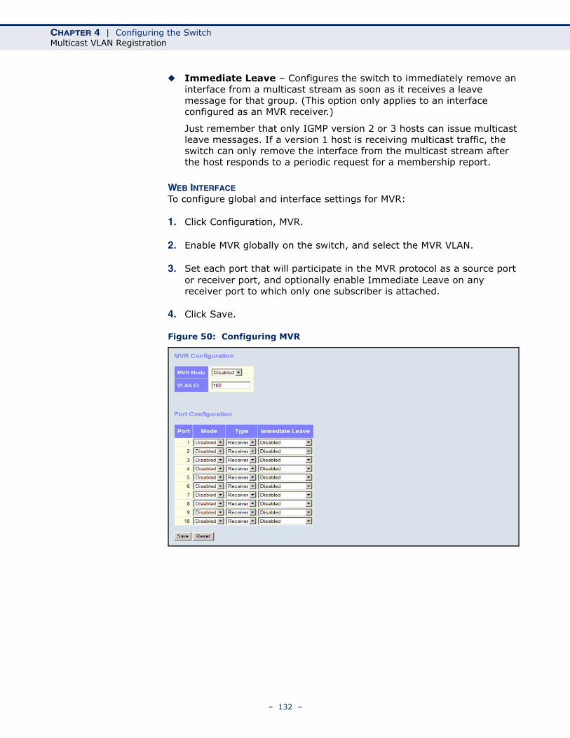
CHAPTER 4 | Configuring the SwitchMulticast VLAN Registration
◆ Immediate Leave – Configures the switch to immediately remove an interface from a multicast stream as soon as it receives a leave message for that group. (This option only applies to an interface configured as an MVR receiver.)
Just remember that only IGMP version 2 or 3 hosts can issue multicast leave messages. If a version 1 host is receiving multicast traffic, the switch can only remove the interface from the multicast stream after the host responds to a periodic request for a membership report.
WEB INTERFACETo configure global and interface settings for MVR:
1. Click Configuration, MVR.
2. Enable MVR globally on the switch, and select the MVR VLAN.
3. Set each port that will participate in the MVR protocol as a source port or receiver port, and optionally enable Immediate Leave on any receiver port to which only one subscriber is attached.
4. Click Save.
Figure 50: Configuring MVR
– 132 –
CHAPTER 4 | Configuring the SwitchIGMP Snooping
IGMP SNOOPING
Multicasting is used to support real-time applications such as videoconferencing or streaming audio. A multicast server does not have to establish a separate connection with each client. It merely broadcasts its service to the network, and any hosts that want to receive the multicast register with their local multicast switch/router. Although this approach reduces the network overhead required by a multicast server, the broadcast traffic must be carefully pruned at every multicast switch/router it passes through to ensure that traffic is only passed on to the hosts which subscribed to this service.
This switch can use Internet Group Management Protocol (IGMP) to filter multicast traffic. IGMP Snooping can be used to passively monitor or “snoop” on exchanges between attached hosts and an IGMP-enabled device, most commonly a multicast router. In this way, the switch can discover the ports that want to join a multicast group, and set its filters accordingly.
If there is no multicast router attached to the local subnet, multicast traffic and query messages may not be received by the switch. In this case (Layer 2) IGMP Query can be used to actively ask the attached hosts if they want to receive a specific multicast service. IGMP Query thereby identifies the ports containing hosts requesting to join the service and sends data out to those ports only. It then propagates the service request up to any neighboring multicast switch/router to ensure that it will continue to receive the multicast service.
The purpose of IP multicast filtering is to optimize a switched network's performance, so multicast packets will only be forwarded to those ports containing multicast group hosts or multicast routers/switches, instead of flooding traffic to all ports in the subnet (VLAN).
CONFIGURING GLOBALAND PORT-RELATED
SETTINGS FOR IGMPSNOOPING
Use the IGMP Snooping Configuration page to configure global and port-related settings which control the forwarding of multicast traffic. Based on the IGMP query and report messages, the switch forwards traffic only to the ports that request multicast traffic. This prevents the switch from broadcasting the traffic to all ports and possibly disrupting network performance.
If multicast routing is not supported on other switches in your network, you can use IGMP Snooping and IGMP Query to monitor IGMP service requests passing between multicast clients and servers, and dynamically configure the switch ports which need to forward multicast traffic.
Multicast routers use information from IGMP snooping and query reports, along with a multicast routing protocol such as DVMRP or PIM, to support IP multicasting across the Internet.
PATH Configuration, IPMC, IGMP Snooping, Basic Configuration
– 133 –
CHAPTER 4 | Configuring the SwitchIGMP Snooping
PARAMETERSThese parameters are displayed:
Global Configuration
◆ Snooping Enabled - When enabled, the switch will monitor network traffic to determine which hosts want to receive multicast traffic. (Default: Enabled)
This switch can passively snoop on IGMP Query and Report packets transferred between IP multicast routers/switches and IP multicast host groups to identify the IP multicast group members. It simply monitors the IGMP packets passing through it, picks out the group registration information, and configures the multicast filters accordingly.
◆ Unregistered IPMC Flooding Enabled - Floods unregistered multicast traffic into the attached VLAN. (Default: Disabled)
Once the table used to store multicast entries for IGMP snooping is filled, no new entries are learned. If no router port is configured in the attached VLAN, and Unregistered IPMC Flooding is disabled, any subsequent multicast traffic not found in the table is dropped, otherwise it is flooded throughout the VLAN.
◆ Leave Proxy Enabled - Suppresses leave messages unless received from the last member port in the group. (Default: Disabled)
IGMP leave proxy suppresses all unnecessary IGMP leave messages so that a non-querier switch forwards an IGMP leave packet only when the last dynamic member port leaves a multicast group.
The leave-proxy feature does not function when a switch is set as the querier. When the switch is a non-querier, the receiving port is not the last dynamic member port in the group, the receiving port is not a router port, and no IGMPv1 member port exists in the group, the switch will generate and send a group-specific (GS) query to the member port which received the leave message, and then start the last member query timer for that port.
When the conditions in the preceding item all apply, except that the receiving port is a router port, then the switch will not send a GS-query, but will immediately start the last member query timer for that port.
Leave proxy is also included in the general proxy function described below. Therefore if Leave Proxy Enabled is not selected, but Proxy Enabled is selected, leave proxy will still be performed.
◆ Proxy Enabled – Enables IGMP Snooping with Proxy Reporting. (Default: Disabled)
When proxy reporting is enabled with this command, the switch performs “IGMP Snooping with Proxy Reporting” (as defined in DSL Forum TR-101, April 2006), including report suppression, last leave, and query suppression.
Report suppression intercepts, absorbs and summarizes IGMP reports coming from downstream hosts. Last leave sends out a proxy query when the last member leaves a multicast group, and query suppression means that neither specific queries nor general queries are forwarded
– 134 –
CHAPTER 4 | Configuring the SwitchIGMP Snooping
from an upstream multicast router to hosts downstream from this device.
When proxy reporting is disabled, all IGMP reports received by the switch are forwarded natively to the upstream multicast routers.
Port Related Configuration
◆ Port – Port identifier.
◆ Router Port - Sets a port to function as a router port, which leads towards a Layer 3 multicast device or IGMP querier. (Default: Disabled)
If IGMP snooping cannot locate the IGMP querier, you can manually designate a port which is connected to a known IGMP querier (i.e., a multicast router/switch). This interface will then join all the current multicast groups supported by the attached router/switch to ensure that multicast traffic is passed to all appropriate interfaces within the switch.
◆ Fast Leave - Immediately deletes a member port of a multicast service if a leave packet is received at that port. (Default: Disabled)
The switch can be configured to immediately delete a member port of a multicast service if a leave packet is received at that port and the Fast Leave function is enabled. This allows the switch to remove a port from the multicast forwarding table without first having to send an IGMP group-specific (GS) query to that interface.
If Fast Leave is not used, a multicast router (or querier) will send a GS-query message when an IGMPv2/v3 group leave message is received. The router/querier stops forwarding traffic for that group only if no host replies to the query within the specified timeout period.
If Fast Leave is enabled, the switch assumes that only one host is connected to the interface. Therefore, Fast Leave should only be enabled on an interface if it is connected to only one IGMP-enabled device, either a service host or a neighbor running IGMP snooping.
Fast Leave is only effective if IGMP snooping is enabled, and IGMPv2 or IGMPv3 snooping is used.
Fast Leave does not apply to a port if the switch has learned that a multicast router is attached to it.
Fast Leave can improve bandwidth usage for a network which frequently experiences many IGMP host add and leave requests.
◆ Throttling - Limits the number of multicast groups to which a port can belong. (Range: 1-10; Default: unlimited)
IGMP throttling sets a maximum number of multicast groups that a port can join at the same time. When the maximum number of groups is reached on a port, any new IGMP join reports will be dropped.
– 135 –
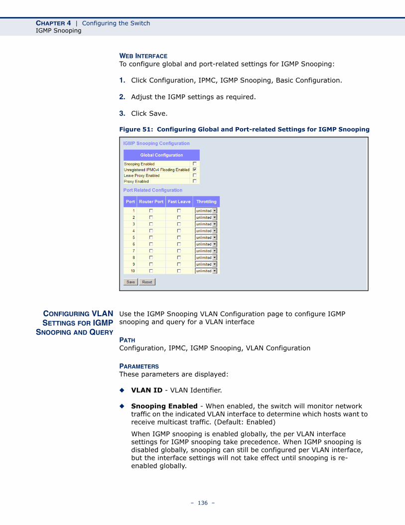
CHAPTER 4 | Configuring the SwitchIGMP Snooping
WEB INTERFACETo configure global and port-related settings for IGMP Snooping:
1. Click Configuration, IPMC, IGMP Snooping, Basic Configuration.
2. Adjust the IGMP settings as required.
3. Click Save.
Figure 51: Configuring Global and Port-related Settings for IGMP Snooping
CONFIGURING VLANSETTINGS FOR IGMP
SNOOPING AND QUERY
Use the IGMP Snooping VLAN Configuration page to configure IGMP snooping and query for a VLAN interface
PATH Configuration, IPMC, IGMP Snooping, VLAN Configuration
PARAMETERSThese parameters are displayed:
◆ VLAN ID - VLAN Identifier.
◆ Snooping Enabled - When enabled, the switch will monitor network traffic on the indicated VLAN interface to determine which hosts want to receive multicast traffic. (Default: Enabled)
When IGMP snooping is enabled globally, the per VLAN interface settings for IGMP snooping take precedence. When IGMP snooping is disabled globally, snooping can still be configured per VLAN interface, but the interface settings will not take effect until snooping is re-enabled globally.
– 136 –
CHAPTER 4 | Configuring the SwitchIGMP Snooping
◆ IGMP Querier - When enabled, the switch can serve as the Querier (on the selected interface), which is responsible for asking hosts if they want to receive multicast traffic. (Default: Disabled)
A router, or multicast-enabled switch, can periodically ask their hosts if they want to receive multicast traffic. If there is more than one router/switch on the LAN performing IP multicasting, one of these devices is elected “querier” and assumes the role of querying the LAN for group members. It then propagates the service requests on to any upstream multicast switch/router to ensure that it will continue to receive the multicast service. This feature is not supported for IGMPv3 snooping.
◆ RV - The Robustness Variable allows tuning for the expected packet loss on a network. A port will be removed from receiving a multicast service when no IGMP reports are detected in response to a number of IGMP queries. The robustness variable sets the number of queries on ports for which there is no report. (Range: 1-255; Default: 2)
Routers adopt the robustness value from the most recently received query. If the querier's robustness variable (QRV) is zero, indicating that the QRV field does not contain a declared robustness value, the switch will set the robustness variable to the value statically configured by this command. If the QRV exceeds 7, the maximum value of the QRV field, the robustness value is set to zero, meaning that this device will not advertise a QRV in any query messages it subsequently sends.
◆ QI - The Query Interval is the interval at which MLD General Queries are sent by the Querier. (Range: 1-255 seconds; Default: 125 seconds)
An MLD general query message is sent by the switch at the interval specified by this attribute. When this message is received by downstream hosts, all receivers build an MLD report for the multicast groups they have joined.
◆ QRI - The Query Response Interval is the Max Response Time advertised in periodic General Queries. The QRI applies when the switch is serving as the querier, and is used to inform other devices of the maximum time this system waits for a response to general queries. (Range: 10-31744 tenths of a second; Default: 10 seconds)
◆ LLQI - The Last Member Query Interval (RFC 3810 – MLDv2 for IP) is used to configure the Last Member Query Interval for IGMP. This attribute sets the interval to wait for a response to a group-specific or group-and-source-specific query message. The overall time to wait for a response (Last Member Query Time) is the value assigned to LLQI, multiplied by the Last Member Query Count (which is fixed at 2). (Range: 1-31744 tenths of a second in multiples of 10; Default: 1 second)
When a multicast host leaves a group, it sends an IGMP leave message. When the leave message is received by the switch, it checks to see if this host is the last to leave the group by sending out an IGMP group-specific or group-and-source-specific query message, and starts a timer. If no reports are received before the timer expires, the group record is deleted, and a report is sent to the upstream multicast router.
– 137 –
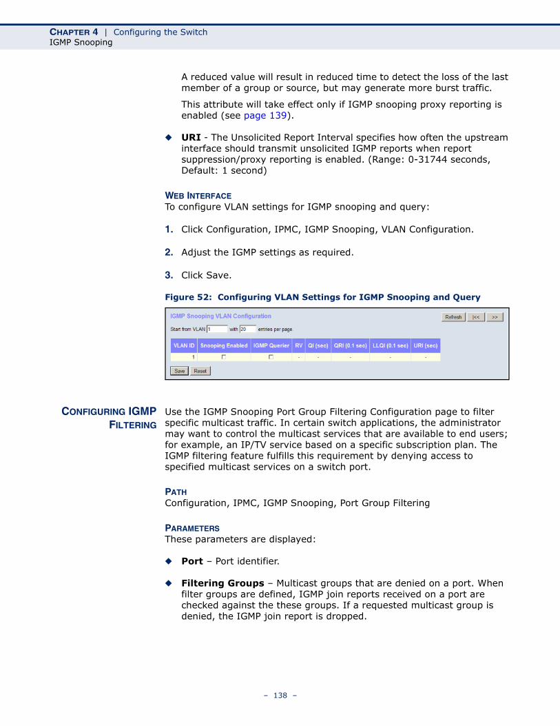
CHAPTER 4 | Configuring the SwitchIGMP Snooping
A reduced value will result in reduced time to detect the loss of the last member of a group or source, but may generate more burst traffic.
This attribute will take effect only if IGMP snooping proxy reporting is enabled (see page 139).
◆ URI - The Unsolicited Report Interval specifies how often the upstream interface should transmit unsolicited IGMP reports when report suppression/proxy reporting is enabled. (Range: 0-31744 seconds, Default: 1 second)
WEB INTERFACETo configure VLAN settings for IGMP snooping and query:
1. Click Configuration, IPMC, IGMP Snooping, VLAN Configuration.
2. Adjust the IGMP settings as required.
3. Click Save.
Figure 52: Configuring VLAN Settings for IGMP Snooping and Query
CONFIGURING IGMPFILTERING
Use the IGMP Snooping Port Group Filtering Configuration page to filter specific multicast traffic. In certain switch applications, the administrator may want to control the multicast services that are available to end users; for example, an IP/TV service based on a specific subscription plan. The IGMP filtering feature fulfills this requirement by denying access to specified multicast services on a switch port.
PATH Configuration, IPMC, IGMP Snooping, Port Group Filtering
PARAMETERSThese parameters are displayed:
◆ Port – Port identifier.
◆ Filtering Groups – Multicast groups that are denied on a port. When filter groups are defined, IGMP join reports received on a port are checked against the these groups. If a requested multicast group is denied, the IGMP join report is dropped.
– 138 –
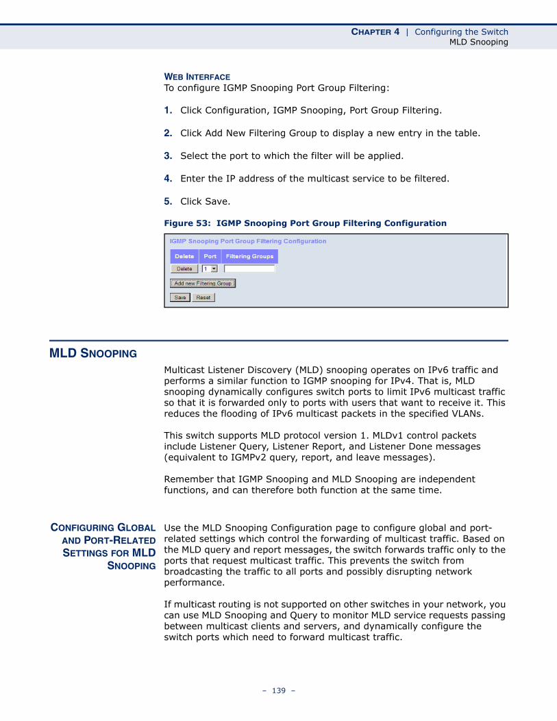
CHAPTER 4 | Configuring the SwitchMLD Snooping
WEB INTERFACETo configure IGMP Snooping Port Group Filtering:
1. Click Configuration, IGMP Snooping, Port Group Filtering.
2. Click Add New Filtering Group to display a new entry in the table.
3. Select the port to which the filter will be applied.
4. Enter the IP address of the multicast service to be filtered.
5. Click Save.
Figure 53: IGMP Snooping Port Group Filtering Configuration
MLD SNOOPING
Multicast Listener Discovery (MLD) snooping operates on IPv6 traffic and performs a similar function to IGMP snooping for IPv4. That is, MLD snooping dynamically configures switch ports to limit IPv6 multicast traffic so that it is forwarded only to ports with users that want to receive it. This reduces the flooding of IPv6 multicast packets in the specified VLANs.
This switch supports MLD protocol version 1. MLDv1 control packets include Listener Query, Listener Report, and Listener Done messages (equivalent to IGMPv2 query, report, and leave messages).
Remember that IGMP Snooping and MLD Snooping are independent functions, and can therefore both function at the same time.
CONFIGURING GLOBALAND PORT-RELATEDSETTINGS FOR MLD
SNOOPING
Use the MLD Snooping Configuration page to configure global and port-related settings which control the forwarding of multicast traffic. Based on the MLD query and report messages, the switch forwards traffic only to the ports that request multicast traffic. This prevents the switch from broadcasting the traffic to all ports and possibly disrupting network performance.
If multicast routing is not supported on other switches in your network, you can use MLD Snooping and Query to monitor MLD service requests passing between multicast clients and servers, and dynamically configure the switch ports which need to forward multicast traffic.
– 139 –
CHAPTER 4 | Configuring the SwitchMLD Snooping
Multicast routers use information from MLD snooping and query reports, along with a multicast routing protocol such as PIMv6, to support IP multicasting across the Internet.
PATH Configuration, IPMC, MLD Snooping, Basic Configuration
PARAMETERSThese parameters are displayed:
Global Configuration
◆ Snooping Enabled - When enabled, the switch will monitor network traffic to determine which hosts want to receive multicast traffic. (Default: Disabled)
This switch can passively snoop on MLD Listener Query and Report packets transferred between IP multicast routers/switches and IP multicast host groups to identify the IP multicast group members. It simply monitors the MLD control packets passing through it, picks out the group registration information, and configures the multicast filters accordingly.
◆ Unregistered IPMCv6 Flooding Enabled - Floods unregistered multicast traffic into the attached VLAN. (Default: Enabled)
Once the table used to store multicast entries for MLD snooping is filled, no new entries are learned. If no router port is configured in the attached VLAN, and Unregistered IPMCv6 Flooding is disabled, any subsequent multicast traffic not found in the table is dropped, otherwise it is flooded throughout the VLAN.
◆ Leave Proxy Enabled - Suppresses leave messages unless received from the last member port in the group. (Default: Disabled)
MLD leave proxy suppresses all unnecessary MLD leave messages so that a non-querier switch forwards an MLD leave packet only when the last dynamic member port leaves a multicast group.
The leave-proxy feature does not function when a switch is set as the querier. When the switch is a non-querier, the receiving port is not the last dynamic member port in the group, and the receiving port is not a router port, the switch will generate and send a group-specific (GS) query to the member port which received the leave message, and then start the last member query timer for that port.
When the conditions in the preceding item all apply, except that the receiving port is a router port, then the switch will not send a GS-query, but will immediately start the last member query timer for that port.
◆ Proxy Enabled - Configures the switch to issue MLD host report messages on behalf of hosts discovered through standard MLD interfaces. (Default: Disabled)
– 140 –
CHAPTER 4 | Configuring the SwitchMLD Snooping
When MLD proxy is enabled, the switch exchanges MLD messages with the router on its upstream interface, and performs the host portion of the MLD task on the upstream interface as follows:
■ When queried, it sends multicast listener reports to the group.
■ When a host joins a multicast group to which no other host belongs, it sends unsolicited multicast listener reports to that group.
■ When the last host in a particular multicast group leaves, it sends an unsolicited multicast listener done report to the all-routers address (FF02::2) for MLDv1.
Port Related Configuration
◆ Port – Port identifier.
◆ Router Port - Sets a port to function as a router port, which leads towards a Layer 3 multicast device or MLD querier. (Default: Disabled)
If MLD snooping cannot locate the MLD querier, you can manually designate a port which is connected to a known MLD querier (i.e., a multicast router/switch). This interface will then join all the current multicast groups supported by the attached router/switch to ensure that multicast traffic is passed to all appropriate interfaces within the switch.
◆ Fast Leave - Immediately deletes a member port of a multicast service if a leave packet is received at that port. (Default: Disabled)
The switch can be configured to immediately delete a member port of a multicast service if a leave packet is received at that port and the Fast Leave function is enabled. This allows the switch to remove a port from the multicast forwarding table without first having to send an MLD group-specific (GS) query to that interface.
If Fast Leave is not used, a multicast router (or querier) will send a GS-query message when a group leave message is received. The router/querier stops forwarding traffic for that group only if no host replies to the query within the specified timeout period.
If Fast Leave is enabled, the switch assumes that only one host is connected to the interface. Therefore, Fast Leave should only be enabled on an interface if it is connected to only one MLD-enabled device, either a service host or a neighbor running MLD snooping.
Fast Leave does not apply to a port if the switch has learned that a multicast router is attached to it.
Fast Leave can improve bandwidth usage for a network which frequently experiences many MLD host add and leave requests.
◆ Throttling - Limits the number of multicast groups to which a port can belong. (Range: 1-10; Default: unlimited)
MLD throttling sets a maximum number of multicast groups that a port can join at the same time. When the maximum number of groups is reached on a port, any new MLD listener reports will be dropped.
– 141 –
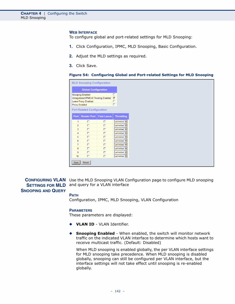
CHAPTER 4 | Configuring the SwitchMLD Snooping
WEB INTERFACETo configure global and port-related settings for MLD Snooping:
1. Click Configuration, IPMC, MLD Snooping, Basic Configuration.
2. Adjust the MLD settings as required.
3. Click Save.
Figure 54: Configuring Global and Port-related Settings for MLD Snooping
CONFIGURING VLANSETTINGS FOR MLD
SNOOPING AND QUERY
Use the MLD Snooping VLAN Configuration page to configure MLD snooping and query for a VLAN interface
PATH Configuration, IPMC, MLD Snooping, VLAN Configuration
PARAMETERSThese parameters are displayed:
◆ VLAN ID - VLAN Identifier.
◆ Snooping Enabled - When enabled, the switch will monitor network traffic on the indicated VLAN interface to determine which hosts want to receive multicast traffic. (Default: Disabled)
When MLD snooping is enabled globally, the per VLAN interface settings for MLD snooping take precedence. When MLD snooping is disabled globally, snooping can still be configured per VLAN interface, but the interface settings will not take effect until snooping is re-enabled globally.
– 142 –
CHAPTER 4 | Configuring the SwitchMLD Snooping
◆ MLD Querier - When enabled, the switch can serve as the MLDv2 Querier if selected in the bidding process with other competing multicast routers/switches, and if selected will be responsible for asking hosts if they want to receive multicast traffic. (Default: Disabled)
A router, or multicast-enabled switch, can periodically ask their hosts if they want to receive multicast traffic. If there is more than one router/switch on the LAN performing IP multicasting, one of these devices is elected “querier” and assumes the role of querying the LAN for group members. It then propagates the service requests on to any upstream multicast router/switch to ensure that it will continue to receive the multicast service.
An IPv6 address must be configured on the VLAN interface from which the querier will act if elected. When serving as the querier, the switch uses this IPv6 address as the query source address.
The querier will not start or will disable itself after having started if it detects an IPv6 multicast router on the network.
◆ RV - The Robustness Variable allows tuning for the expected packet loss on a network. A port will be removed from receiving a multicast service when no MLD reports are detected in response to a number of MLD queries. The robustness variable sets the number of queries on ports for which there is no report. (Range: 1-255; Default: 2)
Routers adopt the robustness value from the most recently received query. If the querier's robustness variable (QRV) is zero, indicating that the QRV field does not contain a declared robustness value, the switch will set the robustness variable to the value statically configured by this command. If the QRV exceeds 7, the maximum value of the QRV field, the robustness value is set to zero, meaning that this device will not advertise a QRV in any query messages it subsequently sends.
◆ QI - The Query Interval is the interval at which General Queries are sent by the Querier. (Range: 1-255 seconds; Default: 125 seconds)
An MLD general query message is sent by the switch at the interval specified by this attribute. When this message is received by downstream hosts, all receivers build an IGMP report for the multicast groups they have joined.
◆ QRI - The Query Response Interval is the Max Response Time advertised in periodic General Queries. The QRI applies when the switch is serving as the querier, and is used to inform other devices of the maximum time this system waits for a response to general queries. (Range: 10-31744 tenths of a second; Default: 10 seconds)
◆ LLQI - The Last Member Query Interval (RFC 3810 – MLDv2 for IP) sets the interval to wait for a response to a group-specific or group-and-source-specific query message. The overall time to wait for a response (Last Member Query Time) is the value assigned to LLQI, multiplied by the Last Member Query Count (which is fixed at 2). (Range: 1-31744 tenths of a second in multiples of 10; Default: 1 second)
– 143 –
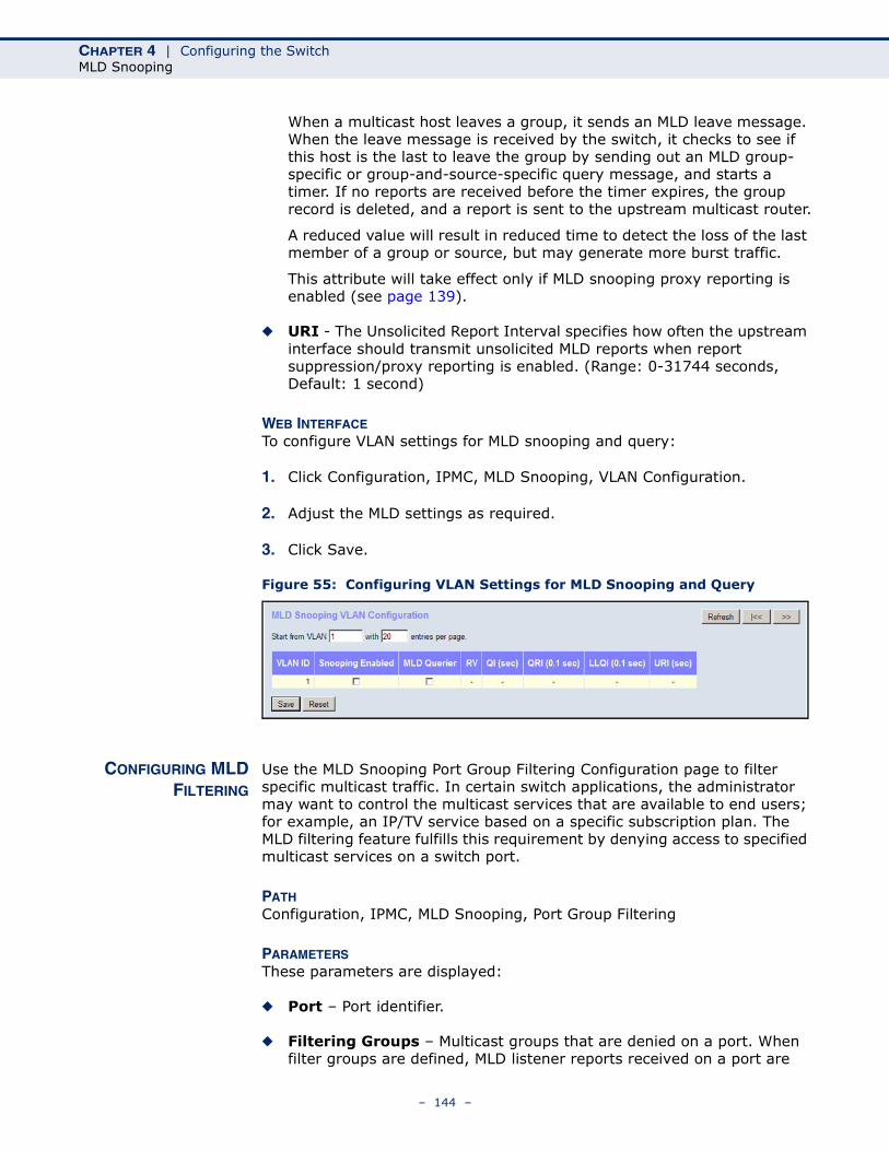
CHAPTER 4 | Configuring the SwitchMLD Snooping
When a multicast host leaves a group, it sends an MLD leave message. When the leave message is received by the switch, it checks to see if this host is the last to leave the group by sending out an MLD group-specific or group-and-source-specific query message, and starts a timer. If no reports are received before the timer expires, the group record is deleted, and a report is sent to the upstream multicast router.
A reduced value will result in reduced time to detect the loss of the last member of a group or source, but may generate more burst traffic.
This attribute will take effect only if MLD snooping proxy reporting is enabled (see page 139).
◆ URI - The Unsolicited Report Interval specifies how often the upstream interface should transmit unsolicited MLD reports when report suppression/proxy reporting is enabled. (Range: 0-31744 seconds, Default: 1 second)
WEB INTERFACETo configure VLAN settings for MLD snooping and query:
1. Click Configuration, IPMC, MLD Snooping, VLAN Configuration.
2. Adjust the MLD settings as required.
3. Click Save.
Figure 55: Configuring VLAN Settings for MLD Snooping and Query
CONFIGURING MLDFILTERING
Use the MLD Snooping Port Group Filtering Configuration page to filter specific multicast traffic. In certain switch applications, the administrator may want to control the multicast services that are available to end users; for example, an IP/TV service based on a specific subscription plan. The MLD filtering feature fulfills this requirement by denying access to specified multicast services on a switch port.
PATH Configuration, IPMC, MLD Snooping, Port Group Filtering
PARAMETERSThese parameters are displayed:
◆ Port – Port identifier.
◆ Filtering Groups – Multicast groups that are denied on a port. When filter groups are defined, MLD listener reports received on a port are
– 144 –
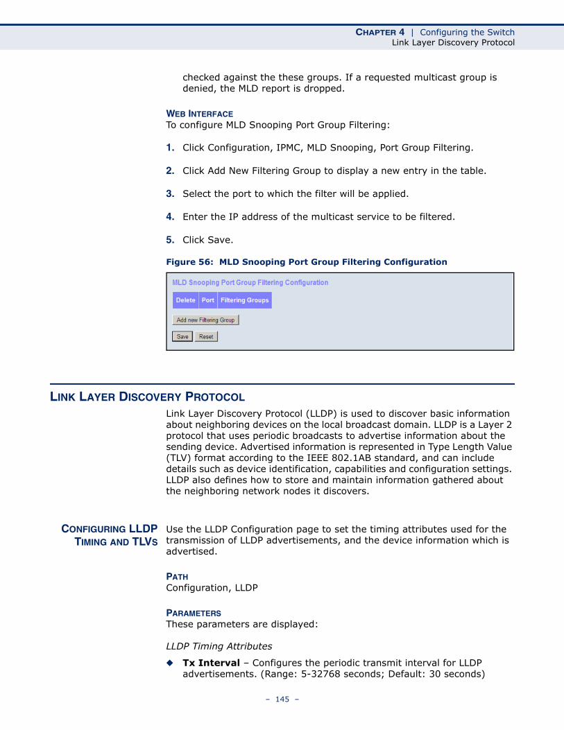
CHAPTER 4 | Configuring the SwitchLink Layer Discovery Protocol
checked against the these groups. If a requested multicast group is denied, the MLD report is dropped.
WEB INTERFACETo configure MLD Snooping Port Group Filtering:
1. Click Configuration, IPMC, MLD Snooping, Port Group Filtering.
2. Click Add New Filtering Group to display a new entry in the table.
3. Select the port to which the filter will be applied.
4. Enter the IP address of the multicast service to be filtered.
5. Click Save.
Figure 56: MLD Snooping Port Group Filtering Configuration
LINK LAYER DISCOVERY PROTOCOL
Link Layer Discovery Protocol (LLDP) is used to discover basic information about neighboring devices on the local broadcast domain. LLDP is a Layer 2 protocol that uses periodic broadcasts to advertise information about the sending device. Advertised information is represented in Type Length Value (TLV) format according to the IEEE 802.1AB standard, and can include details such as device identification, capabilities and configuration settings. LLDP also defines how to store and maintain information gathered about the neighboring network nodes it discovers.
CONFIGURING LLDPTIMING AND TLVS
Use the LLDP Configuration page to set the timing attributes used for the transmission of LLDP advertisements, and the device information which is advertised.
PATH Configuration, LLDP
PARAMETERSThese parameters are displayed:
LLDP Timing Attributes
◆ Tx Interval – Configures the periodic transmit interval for LLDP advertisements. (Range: 5-32768 seconds; Default: 30 seconds)
– 145 –
CHAPTER 4 | Configuring the SwitchLink Layer Discovery Protocol
◆ Tx Hold – Configures the time-to-live (TTL) value sent in LLDP advertisements as shown in the formula below. (Range: 2-10; Default: 3)
The time-to-live tells the receiving LLDP agent how long to retain all information pertaining to the sending LLDP agent if it does not transmit updates in a timely manner.
TTL in seconds is based on the following rule:
minimum value ((Transmission Interval * Holdtime Multiplier), or 65535)
Therefore, the default TTL is 30*3 = 90 seconds.
◆ Tx Delay – Configures a delay between the successive transmission of advertisements initiated by a change in local LLDP MIB variables. (Range: 1-8192 seconds; Default: 2 seconds)
The transmit delay is used to prevent a series of successive LLDP transmissions during a short period of rapid changes in local LLDP MIB objects, and to increase the probability that multiple, rather than single changes, are reported in each transmission.
This attribute must comply with the rule: (4 * Transmission Delay) ≤ Transmission Interval
◆ Tx Reinit – Configures the delay before attempting to re-initialize after LLDP ports are disabled or the link goes down. (Range: 1-10 seconds; Default: 2 seconds)
When LLDP is re-initialized on a port, all information in the remote system’s LLDP MIB associated with this port is deleted.
LLDP Interface Attributes
◆ Port – Port identifier.
◆ Mode – Enables LLDP message transmit and receive modes for LLDP Protocol Data Units. (Options: Disabled, Enabled - TxRx, Rx only, Tx only; Default: Disabled)
◆ CDP Aware – Enables decoding of Cisco Discovery Protocol frames. (Default: Disabled)
If enabled, CDP TLVs that can be mapped into a corresponding field in the LLDP neighbors table are decoded, all others are discarded. CDP TLVs are mapped into LLDP neighbors table as shown below:
■ CDP TLV “Device ID” is mapped into the LLDP “Chassis ID” field.
■ CDP TLV “Address” is mapped into the LLDP “Management Address” field. The CDP address TLV can contain multiple addresses, but only the first address is shown in the LLDP neighbors table.
■ CDP TLV “Port ID” is mapped into the LLDP “Port ID” field.
■ CDP TLV “Version and Platform” is mapped into the LLDP “System Description” field.
■ Both the CDP and LLDP support “system capabilities,” but the CDP capabilities cover capabilities that are not part of LLDP. These capabilities are shown as “others” in the LLDP neighbors table.
– 146 –
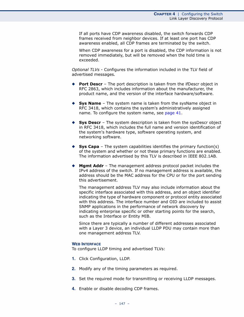
CHAPTER 4 | Configuring the SwitchLink Layer Discovery Protocol
If all ports have CDP awareness disabled, the switch forwards CDP frames received from neighbor devices. If at least one port has CDP awareness enabled, all CDP frames are terminated by the switch.
When CDP awareness for a port is disabled, the CDP information is not removed immediately, but will be removed when the hold time is exceeded.
Optional TLVs - Configures the information included in the TLV field of advertised messages.
◆ Port Descr – The port description is taken from the ifDescr object in RFC 2863, which includes information about the manufacturer, the product name, and the version of the interface hardware/software.
◆ Sys Name – The system name is taken from the sysName object in RFC 3418, which contains the system's administratively assigned name. To configure the system name, see page 41.
◆ Sys Descr – The system description is taken from the sysDescr object in RFC 3418, which includes the full name and version identification of the system's hardware type, software operating system, and networking software.
◆ Sys Capa – The system capabilities identifies the primary function(s) of the system and whether or not these primary functions are enabled. The information advertised by this TLV is described in IEEE 802.1AB.
◆ Mgmt Addr – The management address protocol packet includes the IPv4 address of the switch. If no management address is available, the address should be the MAC address for the CPU or for the port sending this advertisement.
The management address TLV may also include information about the specific interface associated with this address, and an object identifier indicating the type of hardware component or protocol entity associated with this address. The interface number and OID are included to assist SNMP applications in the performance of network discovery by indicating enterprise specific or other starting points for the search, such as the Interface or Entity MIB.
Since there are typically a number of different addresses associated with a Layer 3 device, an individual LLDP PDU may contain more than one management address TLV.
WEB INTERFACETo configure LLDP timing and advertised TLVs:
1. Click Configuration, LLDP.
2. Modify any of the timing parameters as required.
3. Set the required mode for transmitting or receiving LLDP messages.
4. Enable or disable decoding CDP frames.
– 147 –
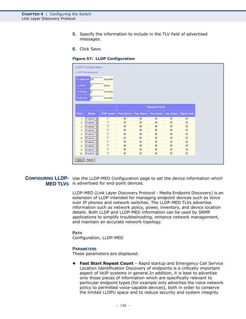
CHAPTER 4 | Configuring the SwitchLink Layer Discovery Protocol
5. Specify the information to include in the TLV field of advertised messages.
6. Click Save.
Figure 57: LLDP Configuration
CONFIGURING LLDP-MED TLVS
Use the LLDP-MED Configuration page to set the device information which is advertised for end-point devices.
LLDP-MED (Link Layer Discovery Protocol - Media Endpoint Discovery) is an extension of LLDP intended for managing endpoint devices such as Voice over IP phones and network switches. The LLDP-MED TLVs advertise information such as network policy, power, inventory, and device location details. Both LLDP and LLDP-MED information can be used by SNMP applications to simplify troubleshooting, enhance network management, and maintain an accurate network topology.
PATH Configuration, LLDP-MED
PARAMETERSThese parameters are displayed:
◆ Fast Start Repeat Count – Rapid startup and Emergency Call Service Location Identification Discovery of endpoints is a critically important aspect of VoIP systems in general.In addition, it is best to advertise only those pieces of information which are specifically relevant to particular endpoint types (for example only advertise the voice network policy to permitted voice-capable devices), both in order to conserve the limited LLDPU space and to reduce security and system integrity
– 148 –
CHAPTER 4 | Configuring the SwitchLink Layer Discovery Protocol
issues that can come with inappropriate knowledge of the network policy.
With this in mind LLDP-MED defines an LLDP-MED Fast Start interaction between the protocol and the application layers on top of the protocol, in order to achieve these related properties. Initially, a Network Connectivity Device will only transmit LLDP TLVs in an LLDPDU. Only after an LLDP-MED Endpoint Device is detected, will an LLDP-MED capable Network Connectivity Device start to advertise LLDP-MED TLVs in outgoing LLDPDUs on the associated port. The LLDP-MED application will temporarily speed up the transmission of the LLDPDU to start within a second, when a new LLDP-MED neighbor has been detected in order share LLDP-MED information as fast as possible to new neighbors.
Because there is a risk that a LLDP frame being lost during transmission between neighbors, it is recommended to repeat the fast start transmission multiple times to increase the possibility for that the neighbors has received the LLDP frame. With Fast start repeat count it is possible to specify the number of times the fast start transmission is repeated. The recommended value is 4 times, giving that 4 LLDP frames with a 1 second interval will be transmitted, when a LLDP frame with new information is received.
It should be noted that LLDP-MED and the LLDP-MED Fast Start mechanism is only intended to run on links between LLDP-MED Network Connectivity Devices and Endpoint Devices, and as such does not apply to links between LAN infrastructure elements, including between Network Connectivity Devices, or to other types of links.
Coordinates Location
◆ Latitude – Normalized to within 0-90 degrees with a maximum of 4 digits. It is possible to specify the direction to either North of the equator or South of the equator.
◆ Longitude – Normalized to within 0-180 degrees with a maximum of 4 digits. It is possible to specify the direction to either East of the prime meridian or West of the prime meridian.
◆ Altitude – Normalized to within -32767 to 32767 with a maximum of 4 digits. It is possible to select between two altitude types (floors or meters).
■ Meters: Representing meters of Altitude defined by the vertical datum specified.
■ Floors: Representing altitude in a form more relevant in buildings which have different floor-to-floor dimensions. An altitude = 0.0 is meaningful even outside a building, and represents ground level at the given latitude and longitude. Inside a building, 0.0 represents the floor level associated with ground level at the main entrance.
◆ Map Datum – The Map Datum used for the coordinates given in this Option.
■ WGS84: (Geographical 3D) - World Geodesic System 1984, CRS Code 4327, Prime Meridian Name: Greenwich.
– 149 –
CHAPTER 4 | Configuring the SwitchLink Layer Discovery Protocol
■ NAD83/NAVD88: North American Datum 1983, CRS Code 4269, Prime Meridian Name: Greenwich; The associated vertical datum is the North American Vertical Datum of 1988 (NAVD88). This datum pair is to be used when referencing locations on land, not near tidal water (which would use Datum = NAD83/MLLW).
■ NAD83/MLLW: North American Datum 1983, CRS Code 4269, Prime Meridian Name: Greenwich; The associated vertical datum is Mean Lower Low Water (MLLW). This datum pair is to be used when referencing locations on water/sea/ocean.
◆ Civic Address Location – IETF Geopriv Civic Address based Location Configuration Information (Civic Address LCI).
■ Country code - The two-letter ISO 3166 country code in capital ASCII letters. (Example: DK, DE or US)
■ State - National subdivisions (state, canton, region, province, prefecture).
■ County - County, parish, gun (Japan), district.■ City - City, township, shi (Japan). (Example: Copenhagen)■ City District - City division, borough, city district, ward, chou
(Japan).■ Block (Neighborhood) - Neighborhood, block.■ Street - Street. (Example: Poppelvej)■ Leading street direction - Leading street direction. (Example: N)■ Trailing street suffix - Trailing street suffix. (Example: SW)■ Street suffix - Street suffix. (Example: Ave, Platz)■ House no. - House number. (Example: 21)■ House no. suffix - House number suffix. (Example: A, 1/2)■ Landmark - Landmark or vanity address. (Example: Columbia
University)■ Additional location info - Additional location information.
(Example: South Wing)■ Name - Name (residence and office occupant). (Example:
Flemming Jahn)■ Zip code - Postal/zip code. (Example: 2791)■ Building - Building (structure). (Example: Low Library)■ Apartment - Unit (Apartment, suite). (Example: Apt 42)■ Floor - Floor. (Example: 4)■ Room no. - Room number. (Example: 450F)■ Place type - Place type. (Example: Office)■ Postal community name - Postal community name.
(Example: Leonia)■ P.O. Box - Post office box (P.O. BOX). (Example: 12345)■ Additional code - Additional code. (Example: 1320300003)
– 150 –
CHAPTER 4 | Configuring the SwitchLink Layer Discovery Protocol
◆ Emergency Call Service – Emergency Call Service (e.g. 911 and others), such as defined by TIA or NENA.
ELIN identifier data format is defined to carry the ELIN identifier as used during emergency call setup to a traditional CAMA or ISDN trunk-based PSAP. This format consists of a numerical digit string, corresponding to the ELIN to be used for emergency calling.
◆ Policies – Network Policy Discovery enables the efficient discovery and diagnosis of mismatched issues with the VLAN configuration, along with the associated Layer 2 and Layer 3 attributes, which apply for a set of specific protocol applications on that port. Improper network policy configurations are a very significant issue in VoIP environments that frequently result in voice quality degradation or loss of service.
Policies are only intended for use with applications that have specific “real-time” network policy requirements, such as interactive voice and/or video services.
The network policy attributes advertised are:
■ Layer 2 VLAN ID (IEEE 802.1Q-2003)
■ Layer 2 priority value (IEEE 802.1D-2004)
■ Layer 3 Diffserv code point (DSCP) value (IETF RFC 2474)
This network policy is potentially advertised and associated with multiple sets of application types supported on a given port. The application types specifically addressed are:
■ Voice
■ Guest Voice
■ Softphone Voice
■ Video Conferencing
■ Streaming Video
■ Control / Signaling (conditionally support a separate network policy for the media types above)
A large network may support multiple VoIP policies across the entire organization, and different policies per application type. LLDP-MED allows multiple policies to be advertised per port, each corresponding to a different application type. Different ports on the same Network Connectivity Device may advertise different sets of policies, based on the authenticated user identity or port configuration.
It should be noted that LLDP-MED is not intended to run on links other than between Network Connectivity Devices and Endpoints, and therefore does not need to advertise the multitude of network policies that frequently run on an aggregated link interior to the LAN.
■ Policy ID – ID for the policy. This is auto generated and will be used when selecting the polices that will be mapped to the specific ports.
■ Application Type – Intended use of the application types:
– 151 –
CHAPTER 4 | Configuring the SwitchLink Layer Discovery Protocol
■ Voice - For use by dedicated IP Telephony handsets and other similar appliances supporting interactive voice services. These devices are typically deployed on a separate VLAN for ease of deployment and enhanced security by isolation from data applications.
■ Voice Signaling (conditional) - For use in network topologies that require a different policy for the voice signaling than for the voice media. This application type should not be advertised if all the same network policies apply as those advertised in the Voice application policy.
■ Guest Voice - Support a separate 'limited feature-set' voice service for guest users and visitors with their own IP Telephony handsets and other similar appliances supporting interactive voice services.
■ Guest Voice Signaling (conditional) - For use in network topologies that require a different policy for the guest voice signaling than for the guest voice media. This application type should not be advertised if all the same network policies apply as those advertised in the Guest Voice application policy.
■ Softphone Voice - For use by softphone applications on typical data centric devices, such as PCs or laptops. This class of endpoints frequently does not support multiple VLANs, if at all, and are typically configured to use an 'untagged’ VLAN or a single 'tagged’ data specific VLAN. When a network policy is defined for use with an 'untagged’ VLAN (see Tagged flag below), then the L2 priority field is ignored and only the DSCP value has relevance.
■ Video Conferencing
■ Streaming Video - For use by broadcast or multicast based video content distribution and other similar applications supporting streaming video services that require specific network policy treatment. Video applications relying on TCP with buffering would not be an intended use of this application type.
■ Video Signaling (conditional) - For use in network topologies that require a separate policy for the video signaling than for the video media. This application type should not be advertised if all the same network policies apply as those advertised in the Video Conferencing application policy.
■ Tag – Tag indicating whether the specified application type is using a “tagged” or an “untagged” VLAN.
Untagged indicates that the device is using an untagged frame format and as such does not include a tag header as defined by IEEE 802.1Q-2003. In this case, both the VLAN ID and the Layer 2 priority fields are ignored and only the DSCP value has relevance.
Tagged indicates that the device is using the IEEE 802.1Q tagged frame format, and that both the VLAN ID and the Layer 2 priority values are being used, as well as the DSCP value. The tagged format includes an additional field, known as the tag header. The
– 152 –
CHAPTER 4 | Configuring the SwitchLink Layer Discovery Protocol
tagged frame format also includes priority tagged frames as defined by IEEE 802.1Q-2003.
■ VLAN ID – VLAN identifier for the port. (Range: 1-4095)
■ L2 Priority – Layer 2 priority used for the specified application type. L2 Priority may specify one of eight priority levels (0 - 7), as defined by IEEE 802.1D-2004. A value of 0 represents use of the default priority as defined in IEEE 802.1D-2004.
■ DSCP – DSCP value used to provide Diffserv node behavior for the specified application type as defined in IETF RFC 2474. DSCP may contain one of 64 code point values (0 - 63). A value of 0 represents use of the default DSCP value as defined in RFC 2475.
◆ Policy Port Configuration – Every port may advertise a unique set of network policies or different attributes for the same network policies, based on the authenticated user identity or port configuration.
■ Port – The port number for which the configuration applies.
■ Policy ID – The set of policies that apply to a given port. The set of policies is selected by marking the check boxes that correspond to the required policies.
WEB INTERFACETo configure LLDP-MED TLVs:
1. Click Configuration, LLDP-MED.
2. Modify any of the timing parameters as required.
3. Set the fast start repeat count, descriptive information for the end-point device, and policies applied to selected ports.
4. Click Save.
– 153 –
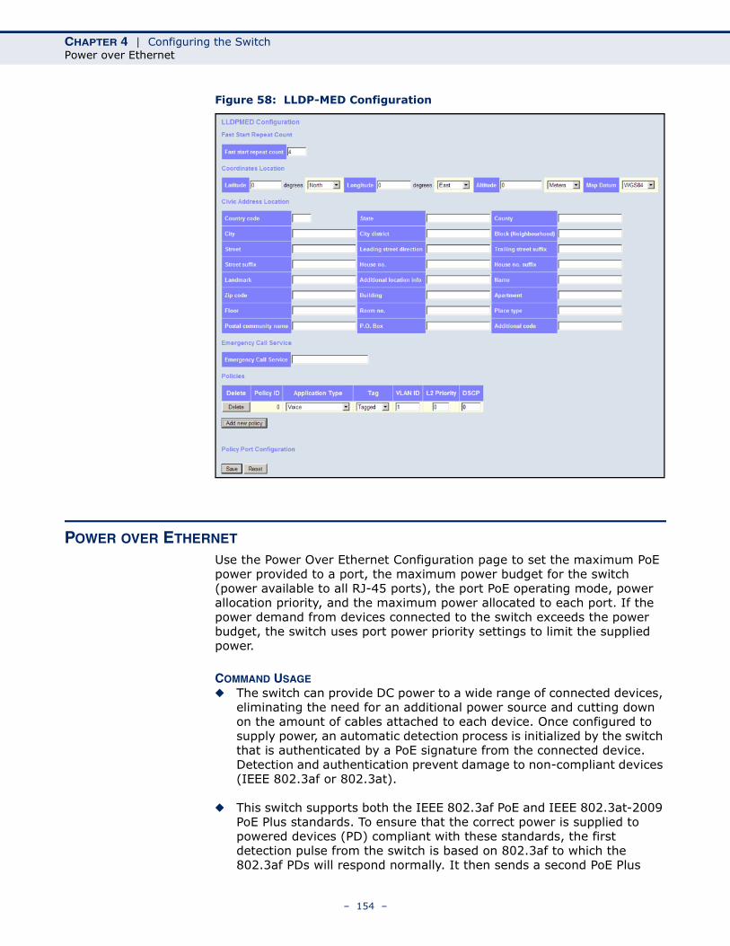
CHAPTER 4 | Configuring the SwitchPower over Ethernet
Figure 58: LLDP-MED Configuration
POWER OVER ETHERNET
Use the Power Over Ethernet Configuration page to set the maximum PoE power provided to a port, the maximum power budget for the switch (power available to all RJ-45 ports), the port PoE operating mode, power allocation priority, and the maximum power allocated to each port. If the power demand from devices connected to the switch exceeds the power budget, the switch uses port power priority settings to limit the supplied power.
COMMAND USAGE◆ The switch can provide DC power to a wide range of connected devices,
eliminating the need for an additional power source and cutting down on the amount of cables attached to each device. Once configured to supply power, an automatic detection process is initialized by the switch that is authenticated by a PoE signature from the connected device. Detection and authentication prevent damage to non-compliant devices (IEEE 802.3af or 802.3at).
◆ This switch supports both the IEEE 802.3af PoE and IEEE 802.3at-2009 PoE Plus standards. To ensure that the correct power is supplied to powered devices (PD) compliant with these standards, the first detection pulse from the switch is based on 802.3af to which the 802.3af PDs will respond normally. It then sends a second PoE Plus
– 154 –
CHAPTER 4 | Configuring the SwitchPower over Ethernet
pulse that causes an 802.3at PD to respond as a Class 4 device and draw Class 4 current. Afterwards, the switch exchanges information with the PD such as duty-cycle, peak and average power needs.
◆ All the RJ-45 ports support both the IEEE 802.3af and IEEE 802.3at standards. The total PoE power delivered by all ports cannot exceed the maximum power budget of 80W.
◆ The switch’s power management enables individual port power to be controlled within the switch’s power budget. Port power can be automatically turned on and off for connected devices, and a per-port power priority can be set so that the switch never exceeds its power budget. When a device is connected to a switch port, its power requirements are detected by the switch before power is supplied. If the power required by a device exceeds the power budget of the port or the whole switch, power is not supplied.
◆ Ports can be set to one of four power priority levels, critical, high, medium, or low. To control the power supply within the switch’s budget, ports set at critical to medium priority have power enabled in preference to those ports set at low priority. For example, when a device connected to a port is set to critical priority, the switch supplies the required power, if necessary by denying power to ports set for a lower priority during bootup.
NOTE: For more information on using the PoE provided by this switch refer to the Installation Guide.
PATH Configuration, PoE
PARAMETERSThese parameters are displayed:
◆ Reserved Power determined by - There are three modes for configuring how the ports or attached Powered Devices (PD) may reserve power:
■ Class – Each port automatically determines how much power to reserve according to the class to which the connected PD belongs, and reserves power accordingly. Four different port classes exist, including 4, 7, 15.4 or 34.2 Watts.
In this mode, the Maximum Power fields have no effect.
■ Allocation – The amount of power that each port may reserve is specified. The allocated/reserved power for each port/PD is specified in the Maximum Power fields.
■ LLDP-MED – This mode is similar to the Class mode expect that each port determines the amount power it reserves by exchanging PoE information using the LLDP protocol and reserves power
– 155 –

CHAPTER 4 | Configuring the SwitchPower over Ethernet
accordingly. If no LLDP information is available for a port, the port will reserve power using the class mode
In this mode the Maximum Power fields have no effect
For all modes, if a port uses more power than the power reserved for that port, it is shut down.
◆ Power Management Mode – There are two modes for configuring when to shut down the ports:
■ Actual Consumption – Ports are shut down when actual power consumption for all ports exceeds the amount of power that the power supply can deliver or if the actual power consumption for a given port exceeds the power reserved for that port. The ports are shut down according to port priority. If two ports have the same priority, the port with the highest port number is shut down.
■ Reserved Power – Ports are shut down when total reserved powered exceeds the amount of power that the power supply can deliver. In this mode the port power is not turned on if the PD requests more power than available from the power supply.
◆ Primary Power Supply - The power budget for the switch. If devices connected to the switch require more power than the switch’s budget, the port power priority settings are used to control the supplied power. (Range: 0-80 Watts)
◆ Port – Port identifier.
◆ PoE Mode – The PoE operating mode for a port includes these options:
■ Disabled – PoE is disabled for the port.
■ PoE – Enables PoE IEEE 802.3af (Class 4 PDs limited to 15.4W)
■ PoE+ – Enables PoE+ IEEE 802.3at (Class 4 PDs limited to 34.2W)
◆ Priority - Port priority is used when remote devices require more power than the power supply can deliver. In this case the port with the lowest priority will be turn off starting from the port with the highest port number.
◆ Maximum Power - The maximum power that can be delivered to a remote device. (Range: 0-34.2 Watts depending on the PoE mode)
WEB INTERFACETo configure global and port-specific PoE settings:
1. Click Configuration, PoE.
2. Set the global PoE parameters, including the method used to determine reserved port power, the method by which port power is shut down, and the switch’s overall power budget.
– 156 –
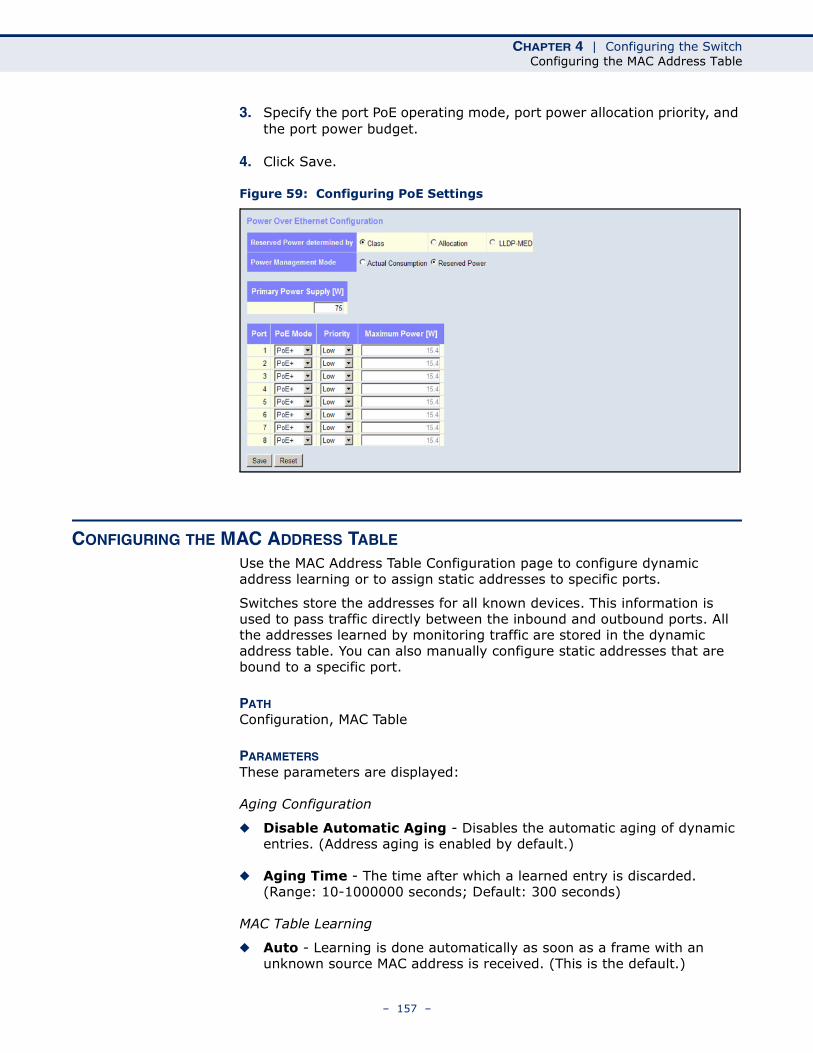
CHAPTER 4 | Configuring the SwitchConfiguring the MAC Address Table
3. Specify the port PoE operating mode, port power allocation priority, and the port power budget.
4. Click Save.
Figure 59: Configuring PoE Settings
CONFIGURING THE MAC ADDRESS TABLE
Use the MAC Address Table Configuration page to configure dynamic address learning or to assign static addresses to specific ports.
Switches store the addresses for all known devices. This information is used to pass traffic directly between the inbound and outbound ports. All the addresses learned by monitoring traffic are stored in the dynamic address table. You can also manually configure static addresses that are bound to a specific port.
PATH Configuration, MAC Table
PARAMETERSThese parameters are displayed:
Aging Configuration
◆ Disable Automatic Aging - Disables the automatic aging of dynamic entries. (Address aging is enabled by default.)
◆ Aging Time - The time after which a learned entry is discarded. (Range: 10-1000000 seconds; Default: 300 seconds)
MAC Table Learning
◆ Auto - Learning is done automatically as soon as a frame with an unknown source MAC address is received. (This is the default.)
– 157 –
CHAPTER 4 | Configuring the SwitchConfiguring the MAC Address Table
◆ Disable - No addresses are learned and stored in the MAC address table.
◆ Secure - Only static MAC address entries are used, all other frames are dropped.
Make sure that the link used for managing the switch is added to the Static MAC Table before changing to secure learning mode. Otherwise the management link will be lost, and can only be restored by using another non-secure port or by connecting to the switch via the serial interface.
NOTE: If the learning mode for a given port in the MAC Learning Table is grayed out, another software module is in control of the mode, so that it cannot be changed by the user. An example of such a module is the MAC-Based Authentication under 802.1X.
Static MAC Table Configuration
◆ VLAN ID - VLAN Identifier. (Range: 1-4095)
◆ MAC Address - Physical address of a device mapped to a port.
A static address can be assigned to a specific port on this switch. Static addresses are bound to the assigned port and will not be moved. When a static address is seen on another port, the address will be ignored and will not be written to the address table.
◆ Port Members - Port identifier.
WEB INTERFACETo configure the MAC Address Table:
1. Click Configuration, MAC Table.
2. Change the address aging time if required.
3. Specify the way in which MAC addresses are learned on any port.
4. Add any required static MAC addresses by clicking the Add New Static Entry button, entering the VLAN ID and MAC address, and marking the ports to which the address is to be mapped.
5. Click Save.
– 158 –
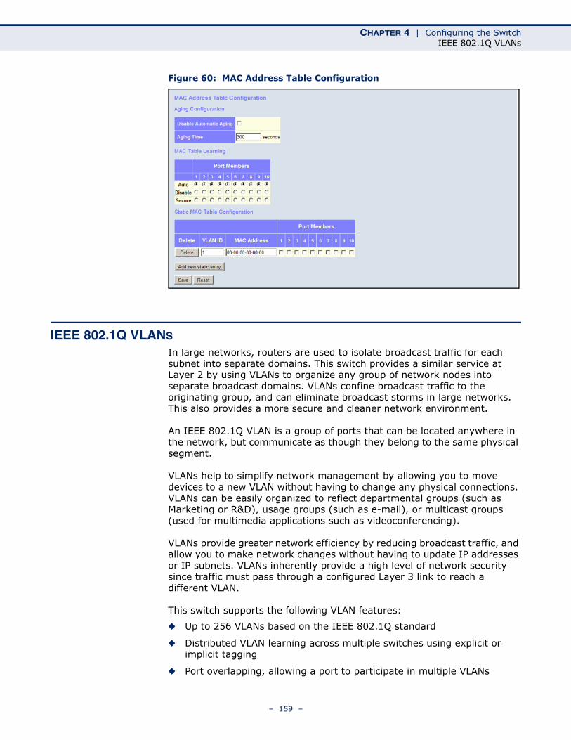
CHAPTER 4 | Configuring the SwitchIEEE 802.1Q VLANs
Figure 60: MAC Address Table Configuration
IEEE 802.1Q VLANS
In large networks, routers are used to isolate broadcast traffic for each subnet into separate domains. This switch provides a similar service at Layer 2 by using VLANs to organize any group of network nodes into separate broadcast domains. VLANs confine broadcast traffic to the originating group, and can eliminate broadcast storms in large networks. This also provides a more secure and cleaner network environment.
An IEEE 802.1Q VLAN is a group of ports that can be located anywhere in the network, but communicate as though they belong to the same physical segment.
VLANs help to simplify network management by allowing you to move devices to a new VLAN without having to change any physical connections. VLANs can be easily organized to reflect departmental groups (such as Marketing or R&D), usage groups (such as e-mail), or multicast groups (used for multimedia applications such as videoconferencing).
VLANs provide greater network efficiency by reducing broadcast traffic, and allow you to make network changes without having to update IP addresses or IP subnets. VLANs inherently provide a high level of network security since traffic must pass through a configured Layer 3 link to reach a different VLAN.
This switch supports the following VLAN features:
◆ Up to 256 VLANs based on the IEEE 802.1Q standard
◆ Distributed VLAN learning across multiple switches using explicit or implicit tagging
◆ Port overlapping, allowing a port to participate in multiple VLANs
– 159 –
CHAPTER 4 | Configuring the SwitchIEEE 802.1Q VLANs
◆ End stations can belong to multiple VLANs
◆ Passing traffic between VLAN-aware and VLAN-unaware devices
◆ Priority tagging
Assigning Ports to VLANs
Before enabling VLANs for the switch, you must first assign each port to the VLAN group(s) in which it will participate. By default all ports are assigned to VLAN 1 as untagged ports. Add a port as a tagged port if you want it to carry traffic for one or more VLANs, and any intermediate network devices or the host at the other end of the connection supports VLANs. Then assign ports on the other VLAN-aware network devices along the path that will carry this traffic to the same VLAN(s), either manually or dynamically using GVRP. However, if you want a port on this switch to participate in one or more VLANs, but none of the intermediate network devices nor the host at the other end of the connection supports VLANs, then you should add this port to the VLAN as an untagged port.
ASSIGNING PORTS TOVLANS
Use the VLAN Membership Configuration page to enable VLANs for this switch by assigning each port to the VLAN group(s) in which it will participate.
PATH Configuration, VLANs, VLAN Membership
PARAMETERSThese parameters are displayed:
◆ VLAN ID - VLAN Identifier. (Range: 1-4095)
◆ VLAN Name - The name of a VLAN. (Range: 1-32 alphanumeric characters)
◆ Port Members - Port identifier.
Port overlapping can be used to allow access to commonly shared network resources among different VLAN groups, such as file servers or printers. Note that if you implement VLANs which do not overlap, but still need to communicate, you must connect them through a router.
– 160 –
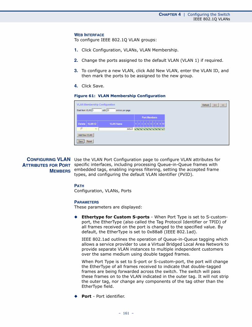
CHAPTER 4 | Configuring the SwitchIEEE 802.1Q VLANs
WEB INTERFACETo configure IEEE 802.1Q VLAN groups:
1. Click Configuration, VLANs, VLAN Membership.
2. Change the ports assigned to the default VLAN (VLAN 1) if required.
3. To configure a new VLAN, click Add New VLAN, enter the VLAN ID, and then mark the ports to be assigned to the new group.
4. Click Save.
Figure 61: VLAN Membership Configuration
CONFIGURING VLANATTRIBUTES FOR PORT
MEMBERS
Use the VLAN Port Configuration page to configure VLAN attributes for specific interfaces, including processing Queue-in-Queue frames with embedded tags, enabling ingress filtering, setting the accepted frame types, and configuring the default VLAN identifier (PVID).
PATH Configuration, VLANs, Ports
PARAMETERSThese parameters are displayed:
◆ Ethertype for Custom S-ports - When Port Type is set to S-custom-port, the EtherType (also called the Tag Protocol Identifier or TPID) of all frames received on the port is changed to the specified value. By default, the EtherType is set to 0x88a8 (IEEE 802.1ad).
IEEE 802.1ad outlines the operation of Queue-in-Queue tagging which allows a service provider to use a Virtual Bridged Local Area Network to provide separate VLAN instances to multiple independent customers over the same medium using double tagged frames.
When Port Type is set to S-port or S-custom-port, the port will change the EtherType of all frames received to indicate that double-tagged frames are being forwarded across the switch. The switch will pass these frames on to the VLAN indicated in the outer tag. It will not strip the outer tag, nor change any components of the tag other than the EtherType field.
◆ Port - Port identifier.
– 161 –
CHAPTER 4 | Configuring the SwitchIEEE 802.1Q VLANs
◆ Port Type – Configures how a port processes the VLAN ID in ingress frames. (Default: Unaware)
■ C-port – For customer ports, each frame is assigned to the VLAN indicated in the VLAN tag, and the tag is removed.
■ S-port – For service ports, the EtherType of all received frames is changed to 0x88a8 to indicate that double-tagged frames are being forwarded across the switch. The switch will pass these frames on to the VLAN indicated in the outer tag. It will not strip the outer tag, nor change any components of the tag other than the EtherType field.
■ S-custom-port – For custom service ports, the EtherType of all received frames is changed to value set in the Ethertype for Custom S-ports field to indicate that double-tagged frames are being forwarded across the switch. The switch will pass these frames on to the VLAN indicated in the outer tag. It will not strip the outer tag, nor change any components of the tag other than the EtherType field.
■ Unaware – All frames are classified to the Port VLAN ID and tags are not removed.
◆ Ingress Filtering - Determines how to process frames tagged for VLANs for which the ingress port is not a member. (Default: Disabled)
■ Ingress filtering only affects tagged frames.
■ If ingress filtering is enabled and a port receives frames tagged for VLANs for which it is not a member, these frames will be discarded.
■ If ingress filtering is disabled and a port receives frames tagged for VLANs for which it is not a member, these frames will be flooded to all other ports.
■ Ingress filtering does not affect VLAN independent BPDU frames, such as GVRP or STP. However, they do affect VLAN dependent BPDU frames, such as GMRP.
◆ Frame Type - Sets the interface to accept all frame types, including tagged or untagged frames, only tagged frames, or only untagged frames. When set to receive all frame types, any received frames that are untagged are assigned to the default VLAN. When set to receive only tagged frames, all untagged frames received on the interface are discarded. (Option: All, Tagged, Untagged; Default: All)
◆ Port VLAN Mode - Determines how to process VLAN tags for ingress and egress traffic. (Options: None, Specific; Default: Specific)
■ None - The ID for the VLAN to which this frame has been assigned is inserted in frames transmitted from the port. The assigned VLAN ID can be based on the ingress tag for tagged frames, or the default PVID for untagged ingress frames. Note that this mode is normally used for ports connected to VLAN-aware switches.
■ Specific - A Port VLAN ID can be configured (as described below). Untagged frames received on the port are classified to the Port VLAN ID. If Port Type is Unaware, all frames received on the port
– 162 –
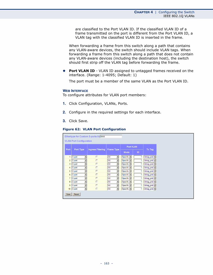
CHAPTER 4 | Configuring the SwitchIEEE 802.1Q VLANs
are classified to the Port VLAN ID. If the classified VLAN ID of a frame transmitted on the port is different from the Port VLAN ID, a VLAN tag with the classified VLAN ID is inserted in the frame.
When forwarding a frame from this switch along a path that contains any VLAN-aware devices, the switch should include VLAN tags. When forwarding a frame from this switch along a path that does not contain any VLAN-aware devices (including the destination host), the switch should first strip off the VLAN tag before forwarding the frame.
◆ Port VLAN ID - VLAN ID assigned to untagged frames received on the interface. (Range: 1-4095; Default: 1)
The port must be a member of the same VLAN as the Port VLAN ID.
WEB INTERFACETo configure attributes for VLAN port members:
1. Click Configuration, VLANs, Ports.
2. Configure in the required settings for each interface.
3. Click Save.
Figure 62: VLAN Port Configuration
– 163 –
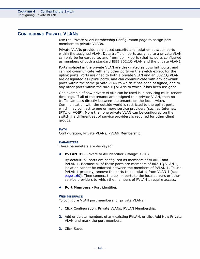
CHAPTER 4 | Configuring the SwitchConfiguring Private VLANs
CONFIGURING PRIVATE VLANS
Use the Private VLAN Membership Configuration page to assign port members to private VLANs.
Private VLANs provide port-based security and isolation between ports within the assigned VLAN. Data traffic on ports assigned to a private VLAN can only be forwarded to, and from, uplink ports (that is, ports configured as members of both a standard IEEE 802.1Q VLAN and the private VLAN).
Ports isolated in the private VLAN are designated as downlink ports, and can not communicate with any other ports on the switch except for the uplink ports. Ports assigned to both a private VLAN and an 802.1Q VLAN are designated as uplink ports, and can communicate with any downlink ports within the same private VLAN to which it has been assigned, and to any other ports within the 802.1Q VLANs to which it has been assigned.
One example of how private VLANs can be used is in servicing multi-tenant dwellings. If all of the tenants are assigned to a private VLAN, then no traffic can pass directly between the tenants on the local switch. Communication with the outside world is restricted to the uplink ports which may connect to one or more service providers (such as Internet, IPTV, or VOIP). More than one private VLAN can be configured on the switch if a different set of service providers is required for other client groups.
PATH Configuration, Private VLANs, PVLAN Membership
PARAMETERSThese parameters are displayed:
◆ PVLAN ID - Private VLAN identifier. (Range: 1-10)
By default, all ports are configured as members of VLAN 1 and PVLAN 1. Because all of these ports are members of 802.1Q VLAN 1, isolation cannot be enforced between the members of PVLAN 1. To use PVLAN 1 properly, remove the ports to be isolated from VLAN 1 (see page 160). Then connect the uplink ports to the local servers or other service providers to which the members of PVLAN 1 require access.
◆ Port Members - Port identifier.
WEB INTERFACETo configure VLAN port members for private VLANs:
1. Click Configuration, Private VLANs, PVLAN Membership.
2. Add or delete members of any existing PVLAN, or click Add New Private VLAN and mark the port members.
3. Click Save.
– 164 –
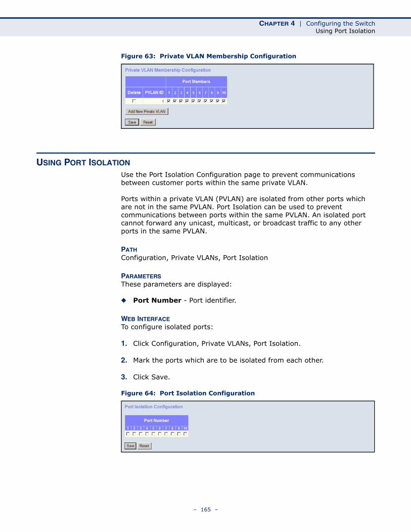
CHAPTER 4 | Configuring the SwitchUsing Port Isolation
Figure 63: Private VLAN Membership Configuration
USING PORT ISOLATION
Use the Port Isolation Configuration page to prevent communications between customer ports within the same private VLAN.
Ports within a private VLAN (PVLAN) are isolated from other ports which are not in the same PVLAN. Port Isolation can be used to prevent communications between ports within the same PVLAN. An isolated port cannot forward any unicast, multicast, or broadcast traffic to any other ports in the same PVLAN.
PATH Configuration, Private VLANs, Port Isolation
PARAMETERSThese parameters are displayed:
◆ Port Number - Port identifier.
WEB INTERFACETo configure isolated ports:
1. Click Configuration, Private VLANs, Port Isolation.
2. Mark the ports which are to be isolated from each other.
3. Click Save.
Figure 64: Port Isolation Configuration
– 165 –
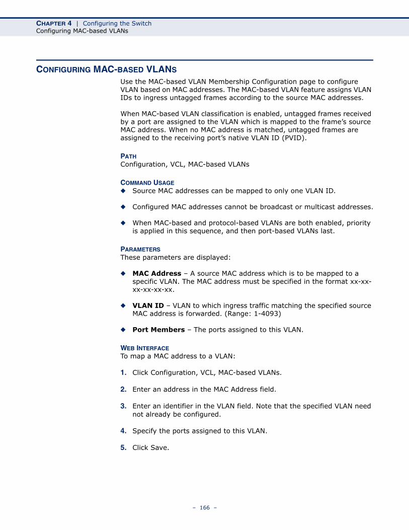
CHAPTER 4 | Configuring the SwitchConfiguring MAC-based VLANs
CONFIGURING MAC-BASED VLANS
Use the MAC-based VLAN Membership Configuration page to configure VLAN based on MAC addresses. The MAC-based VLAN feature assigns VLAN IDs to ingress untagged frames according to the source MAC addresses.
When MAC-based VLAN classification is enabled, untagged frames received by a port are assigned to the VLAN which is mapped to the frame’s source MAC address. When no MAC address is matched, untagged frames are assigned to the receiving port’s native VLAN ID (PVID).
PATH Configuration, VCL, MAC-based VLANs
COMMAND USAGE◆ Source MAC addresses can be mapped to only one VLAN ID.
◆ Configured MAC addresses cannot be broadcast or multicast addresses.
◆ When MAC-based and protocol-based VLANs are both enabled, priority is applied in this sequence, and then port-based VLANs last.
PARAMETERSThese parameters are displayed:
◆ MAC Address – A source MAC address which is to be mapped to a specific VLAN. The MAC address must be specified in the format xx-xx-xx-xx-xx-xx.
◆ VLAN ID – VLAN to which ingress traffic matching the specified source MAC address is forwarded. (Range: 1-4093)
◆ Port Members – The ports assigned to this VLAN.
WEB INTERFACETo map a MAC address to a VLAN:
1. Click Configuration, VCL, MAC-based VLANs.
2. Enter an address in the MAC Address field.
3. Enter an identifier in the VLAN field. Note that the specified VLAN need not already be configured.
4. Specify the ports assigned to this VLAN.
5. Click Save.
– 166 –
CHAPTER 4 | Configuring the SwitchProtocol VLANs
Figure 65: Configuring MAC-Based VLANs
PROTOCOL VLANS The network devices required to support multiple protocols cannot be easily grouped into a common VLAN. This may require non-standard devices to pass traffic between different VLANs in order to encompass all the devices participating in a specific protocol. This kind of configuration deprives users of the basic benefits of VLANs, including security and easy accessibility.
To avoid these problems, you can configure this switch with protocol-based VLANs that divide the physical network into logical VLAN groups for each required protocol. When a frame is received at a port, its VLAN membership can then be determined based on the protocol type being used by the inbound packets.
COMMAND USAGE◆ To configure protocol-based VLANs, follow these steps:
1. First configure VLAN groups for the protocols you want to use (page 160). Although not mandatory, we suggest configuring a separate VLAN for each major protocol running on your network. Do not add port members at this time.
2. Create a protocol group for each of the protocols you want to assign to a VLAN using the Configure Protocol (Add) page.
3. Then map the protocol for each interface to the appropriate VLAN using the Configure Interface (Add) page.
◆ When MAC-based, IP subnet-based, and protocol-based VLANs are supported concurrently, priority is applied in this sequence, and then port-based VLANs last.
– 167 –
CHAPTER 4 | Configuring the SwitchProtocol VLANs
CONFIGURINGPROTOCOL VLAN
GROUPS
Use the Protocol to Group Mapping Table to create protocol groups.
PATH Configuration, VCL, Protocol-based VLANs, Protocol to Group
PARAMETERSThese parameters are displayed:
◆ Frame Type – Choose Ethernet, LLC (Logical Link Control), or SNAP (SubNetwork Access Protocol - RFC 1042) as the frame type used by this protocol.
◆ Value – Values which define the specific protocol type. The fields displayed depend on the selected frame type:
Ethernet – EtherType value. (Range: 0x0600-0xffff; Default: 0x0800)
LLC – Includes the DSAP (Destination Service Access Point) and SSAP (Source Service Access Point) values. (Range: 0x00-0xff; Default: 0xff)
SNAP – Includes OUI (Organizationally Unique Identifier) and PID (Protocol ID) values:
■ OUI – A value in the format of xx-xx-xx where each pair (xx) in the string is a hexadecimal value in the ranges of 0x00-0xff.
■ PID – If the OUI is hexadecimal 000000, the protocol ID is the Ethernet type (EtherType) field value for the protocol running on top of SNAP. If the OUI is that of a particular organization, the protocol ID is a value assigned by that organization to the protocol running on top of SNAP.
In other words, if value of the OUI field is 00-00-00, then value of the PID will be etherType (0x0600-0xffff), and if value of the OUI is other than 00-00-00, then valid value of the PID will be any value from 0x0000 to 0xffff.
◆ Group Name – The name assigned to the Protocol VLAN Group. This name must be a unique 16-character long string which consists of a combination of alphabetic characters (a-z or A-Z) or integers (0-9).
NOTE: Traffic which matches IP Protocol Ethernet Frames is mapped to the VLAN (VLAN 1 by default) that has been configured with the switch's administrative IP. IP Protocol Ethernet traffic must not be mapped to another VLAN or you will lose administrative network connectivity to the switch. If lost in this manner, network access can be regained by using the Reset button to restore the factory default settings.
– 168 –
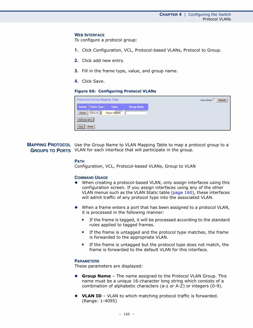
CHAPTER 4 | Configuring the SwitchProtocol VLANs
WEB INTERFACETo configure a protocol group:
1. Click Configuration, VCL, Protocol-based VLANs, Protocol to Group.
2. Click add new entry.
3. Fill in the frame type, value, and group name.
4. Click Save.
Figure 66: Configuring Protocol VLANs
MAPPING PROTOCOLGROUPS TO PORTS
Use the Group Name to VLAN Mapping Table to map a protocol group to a VLAN for each interface that will participate in the group.
PATH Configuration, VCL, Protocol-based VLANs, Group to VLAN
COMMAND USAGE◆ When creating a protocol-based VLAN, only assign interfaces using this
configuration screen. If you assign interfaces using any of the other VLAN menus such as the VLAN Static table (page 160), these interfaces will admit traffic of any protocol type into the associated VLAN.
◆ When a frame enters a port that has been assigned to a protocol VLAN, it is processed in the following manner:
■ If the frame is tagged, it will be processed according to the standard rules applied to tagged frames.
■ If the frame is untagged and the protocol type matches, the frame is forwarded to the appropriate VLAN.
■ If the frame is untagged but the protocol type does not match, the frame is forwarded to the default VLAN for this interface.
PARAMETERSThese parameters are displayed:
◆ Group Name – The name assigned to the Protocol VLAN Group. This name must be a unique 16-character long string which consists of a combination of alphabetic characters (a-z or A-Z) or integers (0-9).
◆ VLAN ID – VLAN to which matching protocol traffic is forwarded. (Range: 1-4095)
– 169 –
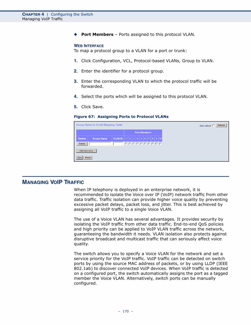
CHAPTER 4 | Configuring the SwitchManaging VoIP Traffic
◆ Port Members – Ports assigned to this protocol VLAN.
WEB INTERFACETo map a protocol group to a VLAN for a port or trunk:
1. Click Configuration, VCL, Protocol-based VLANs, Group to VLAN.
2. Enter the identifier for a protocol group.
3. Enter the corresponding VLAN to which the protocol traffic will be forwarded.
4. Select the ports which will be assigned to this protocol VLAN.
5. Click Save.
Figure 67: Assigning Ports to Protocol VLANs
MANAGING VOIP TRAFFIC
When IP telephony is deployed in an enterprise network, it is recommended to isolate the Voice over IP (VoIP) network traffic from other data traffic. Traffic isolation can provide higher voice quality by preventing excessive packet delays, packet loss, and jitter. This is best achieved by assigning all VoIP traffic to a single Voice VLAN.
The use of a Voice VLAN has several advantages. It provides security by isolating the VoIP traffic from other data traffic. End-to-end QoS policies and high priority can be applied to VoIP VLAN traffic across the network, guaranteeing the bandwidth it needs. VLAN isolation also protects against disruptive broadcast and multicast traffic that can seriously affect voice quality.
The switch allows you to specify a Voice VLAN for the network and set a service priority for the VoIP traffic. VoIP traffic can be detected on switch ports by using the source MAC address of packets, or by using LLDP (IEEE 802.1ab) to discover connected VoIP devices. When VoIP traffic is detected on a configured port, the switch automatically assigns the port as a tagged member the Voice VLAN. Alternatively, switch ports can be manually configured.
– 170 –
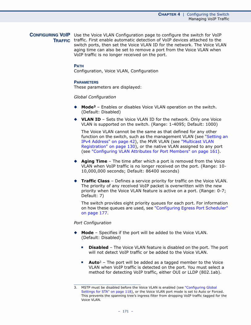
CHAPTER 4 | Configuring the SwitchManaging VoIP Traffic
CONFIGURING VOIPTRAFFIC
Use the Voice VLAN Configuration page to configure the switch for VoIP traffic. First enable automatic detection of VoIP devices attached to the switch ports, then set the Voice VLAN ID for the network. The Voice VLAN aging time can also be set to remove a port from the Voice VLAN when VoIP traffic is no longer received on the port.
PATH Configuration, Voice VLAN, Configuration
PARAMETERSThese parameters are displayed:
Global Configuration
◆ Mode3 – Enables or disables Voice VLAN operation on the switch. (Default: Disabled)
◆ VLAN ID – Sets the Voice VLAN ID for the network. Only one Voice VLAN is supported on the switch. (Range: 1-4095; Default: 1000)
The Voice VLAN cannot be the same as that defined for any other function on the switch, such as the management VLAN (see "Setting an IPv4 Address" on page 42), the MVR VLAN (see "Multicast VLAN Registration" on page 130), or the native VLAN assigned to any port (see "Configuring VLAN Attributes for Port Members" on page 161).
◆ Aging Time – The time after which a port is removed from the Voice VLAN when VoIP traffic is no longer received on the port. (Range: 10-10,000,000 seconds; Default: 86400 seconds)
◆ Traffic Class – Defines a service priority for traffic on the Voice VLAN. The priority of any received VoIP packet is overwritten with the new priority when the Voice VLAN feature is active on a port. (Range: 0-7; Default: 7)
The switch provides eight priority queues for each port. For information on how these queues are used, see "Configuring Egress Port Scheduler" on page 177.
Port Configuration
◆ Mode – Specifies if the port will be added to the Voice VLAN. (Default: Disabled)
■ Disabled – The Voice VLAN feature is disabled on the port. The port will not detect VoIP traffic or be added to the Voice VLAN.
■ Auto3 – The port will be added as a tagged member to the Voice VLAN when VoIP traffic is detected on the port. You must select a method for detecting VoIP traffic, either OUI or LLDP (802.1ab).
3. MSTP must be disabled before the Voice VLAN is enabled (see "Configuring Global Settings for STA" on page 118), or the Voice VLAN port mode is set to Auto or Forced. This prevents the spanning tree’s ingress filter from dropping VoIP traffic tagged for the Voice VLAN.
– 171 –
CHAPTER 4 | Configuring the SwitchManaging VoIP Traffic
When OUI is selected, be sure to configure the MAC address ranges in the Telephony OUI list.
■ Forced3 – The Voice VLAN feature is enabled on the port.
◆ Security – Enables security filtering that discards any non-VoIP packets received on the port that are tagged with the voice VLAN ID. VoIP traffic is identified by source MAC addresses configured in the Telephony OUI list, or through LLDP which is used to discover VoIP devices attached to the switch. Packets received from non-VoIP sources are dropped. (Default: Disabled)
◆ Discovery Protocol – Selects a method to use for detecting VoIP traffic on the port. (Default: OUI)
■ OUI – Traffic from VoIP devices is detected by the Organizationally Unique Identifier (OUI) of the source MAC address. OUI numbers are assigned to manufacturers and form the first three octets of a device MAC address. MAC address OUI numbers must be configured in the Telephony OUI list so that the switch recognizes the traffic as being from a VoIP device.
■ LLDP – Uses LLDP (IEEE 802.1ab) to discover VoIP devices attached to the port. LLDP checks that the “telephone bit” in the system capability TLV is turned on. See "Link Layer Discovery Protocol" for more information on LLDP.
■ Both – Both OUI table lookup and LLDP are used to detect VoIP traffic on a port.
This option only works when the detection mode is set to “Auto.” LLDP should also be enabled before setting the discovery protocol to “LLDP” or “Both.” Note that changing the discovery protocol to “OUI” or “LLDP” will restart auto detection process.
WEB INTERFACETo configure VoIP traffic settings:
1. Click Configuration, Voice VLAN, Configuration.
2. Configure any required changes to the VoIP settings for the switch or for a specific port.
3. Click Save.
– 172 –
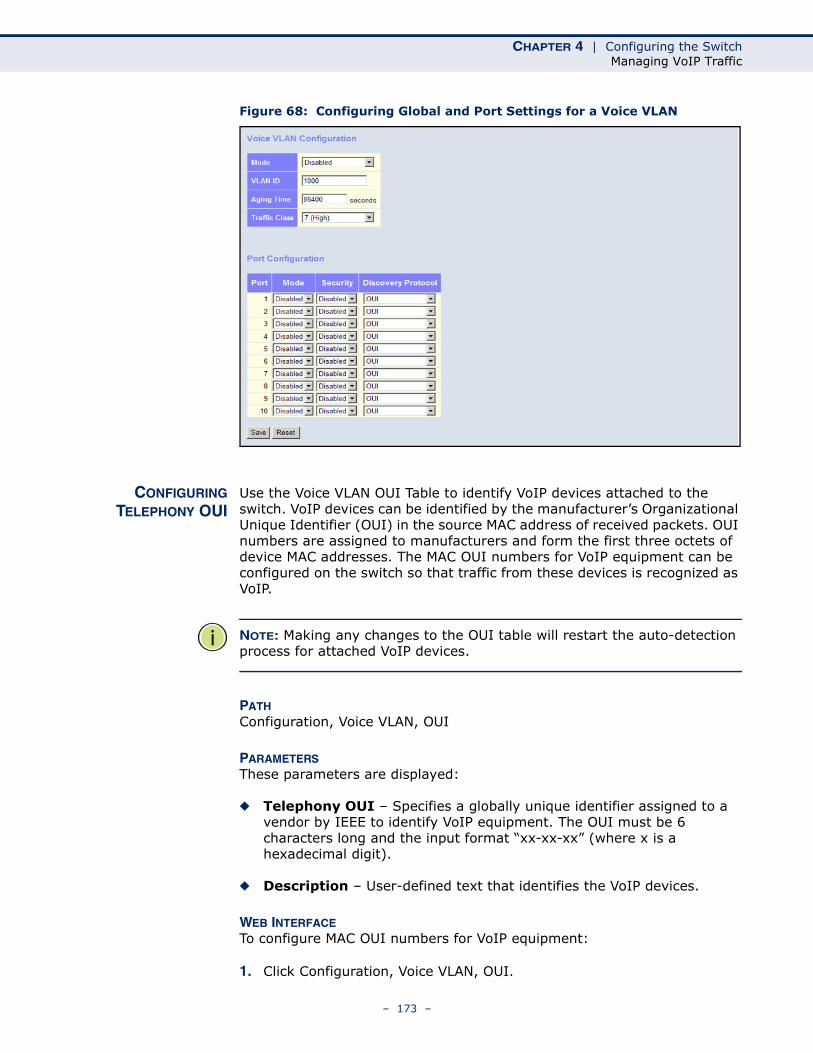
CHAPTER 4 | Configuring the SwitchManaging VoIP Traffic
Figure 68: Configuring Global and Port Settings for a Voice VLAN
CONFIGURINGTELEPHONY OUI
Use the Voice VLAN OUI Table to identify VoIP devices attached to the switch. VoIP devices can be identified by the manufacturer’s Organizational Unique Identifier (OUI) in the source MAC address of received packets. OUI numbers are assigned to manufacturers and form the first three octets of device MAC addresses. The MAC OUI numbers for VoIP equipment can be configured on the switch so that traffic from these devices is recognized as VoIP.
NOTE: Making any changes to the OUI table will restart the auto-detection process for attached VoIP devices.
PATH Configuration, Voice VLAN, OUI
PARAMETERSThese parameters are displayed:
◆ Telephony OUI – Specifies a globally unique identifier assigned to a vendor by IEEE to identify VoIP equipment. The OUI must be 6 characters long and the input format “xx-xx-xx” (where x is a hexadecimal digit).
◆ Description – User-defined text that identifies the VoIP devices.
WEB INTERFACETo configure MAC OUI numbers for VoIP equipment:
1. Click Configuration, Voice VLAN, OUI.
– 173 –
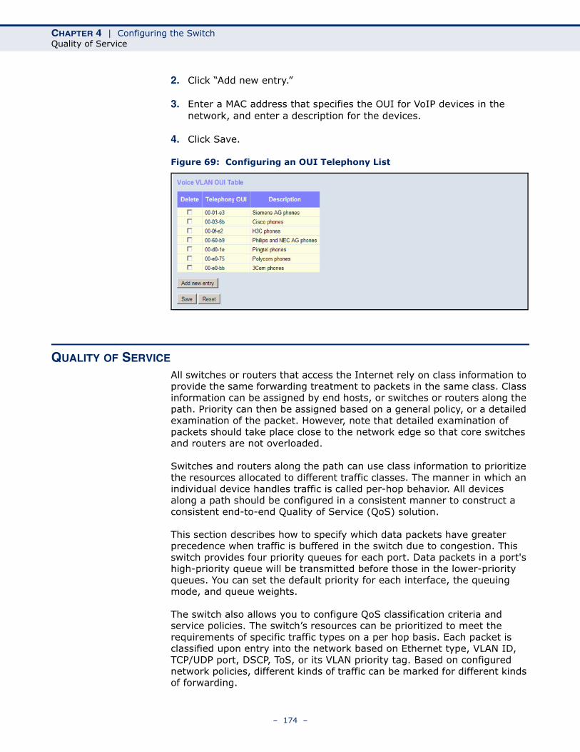
CHAPTER 4 | Configuring the SwitchQuality of Service
2. Click “Add new entry.”
3. Enter a MAC address that specifies the OUI for VoIP devices in the network, and enter a description for the devices.
4. Click Save.
Figure 69: Configuring an OUI Telephony List
QUALITY OF SERVICE
All switches or routers that access the Internet rely on class information to provide the same forwarding treatment to packets in the same class. Class information can be assigned by end hosts, or switches or routers along the path. Priority can then be assigned based on a general policy, or a detailed examination of the packet. However, note that detailed examination of packets should take place close to the network edge so that core switches and routers are not overloaded.
Switches and routers along the path can use class information to prioritize the resources allocated to different traffic classes. The manner in which an individual device handles traffic is called per-hop behavior. All devices along a path should be configured in a consistent manner to construct a consistent end-to-end Quality of Service (QoS) solution.
This section describes how to specify which data packets have greater precedence when traffic is buffered in the switch due to congestion. This switch provides four priority queues for each port. Data packets in a port's high-priority queue will be transmitted before those in the lower-priority queues. You can set the default priority for each interface, the queuing mode, and queue weights.
The switch also allows you to configure QoS classification criteria and service policies. The switch’s resources can be prioritized to meet the requirements of specific traffic types on a per hop basis. Each packet is classified upon entry into the network based on Ethernet type, VLAN ID, TCP/UDP port, DSCP, ToS, or its VLAN priority tag. Based on configured network policies, different kinds of traffic can be marked for different kinds of forwarding.
– 174 –
CHAPTER 4 | Configuring the SwitchQuality of Service
CONFIGURING PORTCLASSIFICATION
Use the QoS Ingress Port Classification page to set the basic QoS parameters for a port, including the default traffic class, DP level (IEEE 802.1p), user priority, drop eligible indicator, classification mode for tagged frames, and DSCP-based QoS classification.
PATH Configuration, QoS, Port Classification
PARAMETERSThese parameters are displayed:
QoS Ingress Port Classification
◆ Port – Port identifier.
◆ QoS class – Controls the default QoS class, i.e., the QoS class for frames not classified in any other way. There is a one to one mapping between QoS class, queue and priority. A QoS class of 0 (zero) has the lowest priority. (Range: 0-7; Default: 0)
◆ DP level – Controls the default drop priority for frames not classified in any other way. (Range: 0-1; Default: 0)
◆ PCP – Controls the default Priority Code Point (or User Priority) for untagged frames. (Range: 0-7; Default: 0)
◆ DEI – Controls the default Drop Eligible Indicator for untagged frames. (Range: 0-1; Default: 0)
◆ Tag Class. – Shows classification mode for tagged frames on this port:
■ Disabled – Uses the default QoS class and DP level for tagged frames.
■ Enabled – Uses the mapped versions of PCP and DEI for tagged frames.
Click on the mode in order to configure the mode and/or mapping.
◆ DSCP Based – Click to Enable DSCP Based QoS Ingress Port Classification (see page 185).
QoS Ingress Port Tag Classification
◆ Tag Classification – Sets classification mode for tagged frames on this port:
■ Disabled – Uses the default QoS class and DP level for tagged frames. (This is the default.)
■ Enabled – Uses the mapped versions of PCP and DEI for tagged frames.
◆ PCP/DEI – Shows the mapping options for classified (PCP, DEI) to (QoS class, DP level) values when Tag Classification is Enabled.
– 175 –
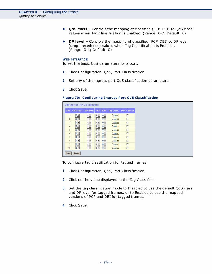
CHAPTER 4 | Configuring the SwitchQuality of Service
◆ QoS class – Controls the mapping of classified (PCP, DEI) to QoS class values when Tag Classification is Enabled. (Range: 0-7; Default: 0)
◆ DP level – Controls the mapping of classified (PCP, DEI) to DP level (drop precedence) values when Tag Classification is Enabled. (Range: 0-1; Default: 0)
WEB INTERFACETo set the basic QoS parameters for a port:
1. Click Configuration, QoS, Port Classification.
2. Set any of the ingress port QoS classification parameters.
3. Click Save.
Figure 70: Configuring Ingress Port QoS Classification
To configure tag classification for tagged frames:
1. Click Configuration, QoS, Port Classification.
2. Click on the value displayed in the Tag Class field.
3. Set the tag classification mode to Disabled to use the default QoS class and DP level for tagged frames, or to Enabled to use the mapped versions of PCP and DEI for tagged frames.
4. Click Save.
– 176 –
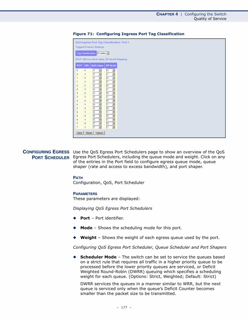
CHAPTER 4 | Configuring the SwitchQuality of Service
Figure 71: Configuring Ingress Port Tag Classification
CONFIGURING EGRESSPORT SCHEDULER
Use the QoS Egress Port Schedulers page to show an overview of the QoS Egress Port Schedulers, including the queue mode and weight. Click on any of the entries in the Port field to configure egress queue mode, queue shaper (rate and access to excess bandwidth), and port shaper.
PATH Configuration, QoS, Port Scheduler
PARAMETERSThese parameters are displayed:
Displaying QoS Egress Port Schedulers
◆ Port – Port identifier.
◆ Mode – Shows the scheduling mode for this port.
◆ Weight – Shows the weight of each egress queue used by the port.
Configuring QoS Egress Port Scheduler, Queue Scheduler and Port Shapers
◆ Scheduler Mode – The switch can be set to service the queues based on a strict rule that requires all traffic in a higher priority queue to be processed before the lower priority queues are serviced, or Deficit Weighted Round-Robin (DWRR) queuing which specifies a scheduling weight for each queue. (Options: Strict, Weighted; Default: Strict)
DWRR services the queues in a manner similar to WRR, but the next queue is serviced only when the queue’s Deficit Counter becomes smaller than the packet size to be transmitted.
– 177 –
CHAPTER 4 | Configuring the SwitchQuality of Service
Note that weighted scheduling uses a combination of weighted service for queues 0 - 6, and strict service for the high priority queues 7 and 8.
◆ Queue Shaper – Controls whether queue shaping is enabled for this queue on this port.
■ Enable – Enables or disables queue shaping. (Default: Disabled)
■ Rate – Controls the rate for the queue shaper. The default value is 500. This value is restricted to 100-1000000 kbps, or 1-3300 Mbps.
■ Unit – Controls the unit of measure for the queue shaper rate as “kbps” or “Mbps.” (Default: kbps)
■ Excess – Controls whether the queue is allowed to use excess bandwidth. (Default: Disabled)
◆ Queue Scheduler – When the Scheduler Mode is set to Weighted, you need to specify a relative weight for each queue. DWRR uses a predefined relative weight for each queue that determines the percentage of service time the switch services each queue before moving on to the next queue. This prevents the head-of-line blocking that can occur with strict priority queuing.
■ Weight – A weight assigned to each of the queues (and thereby to the corresponding traffic priorities). This weight sets the frequency at which each queue is polled for service, and subsequently affects the response time for software applications assigned a specific priority value. (Range: 1-100; Default: 17)
■ Percent – The weight as a percentage for this queue.
◆ Port Shaper – Sets the rate at which traffic can egress this queue.
■ Enable – Enables or disables port shaping. (Default: Disabled)
■ Rate – Controls the rate for the port shaper. The default value is 500. This value is restricted to 100-1000000 kbps, or 1-3300 Mbps
■ Unit – Controls the unit of measure for the port shaper rate as “kbps” or “Mbps.” (Default: kbps)
WEB INTERFACETo show an overview of the queue mode and weight used by egress ports:
1. Click Configuration, QoS, Port Scheduler.
2. Click on any enter under the Port field to configure the Port Scheduler and Shaper.
– 178 –
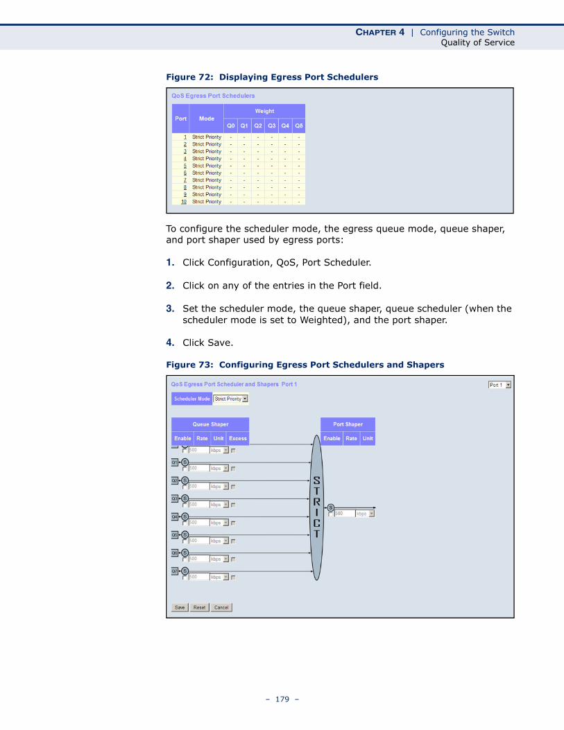
CHAPTER 4 | Configuring the SwitchQuality of Service
Figure 72: Displaying Egress Port Schedulers
To configure the scheduler mode, the egress queue mode, queue shaper, and port shaper used by egress ports:
1. Click Configuration, QoS, Port Scheduler.
2. Click on any of the entries in the Port field.
3. Set the scheduler mode, the queue shaper, queue scheduler (when the scheduler mode is set to Weighted), and the port shaper.
4. Click Save.
Figure 73: Configuring Egress Port Schedulers and Shapers
– 179 –
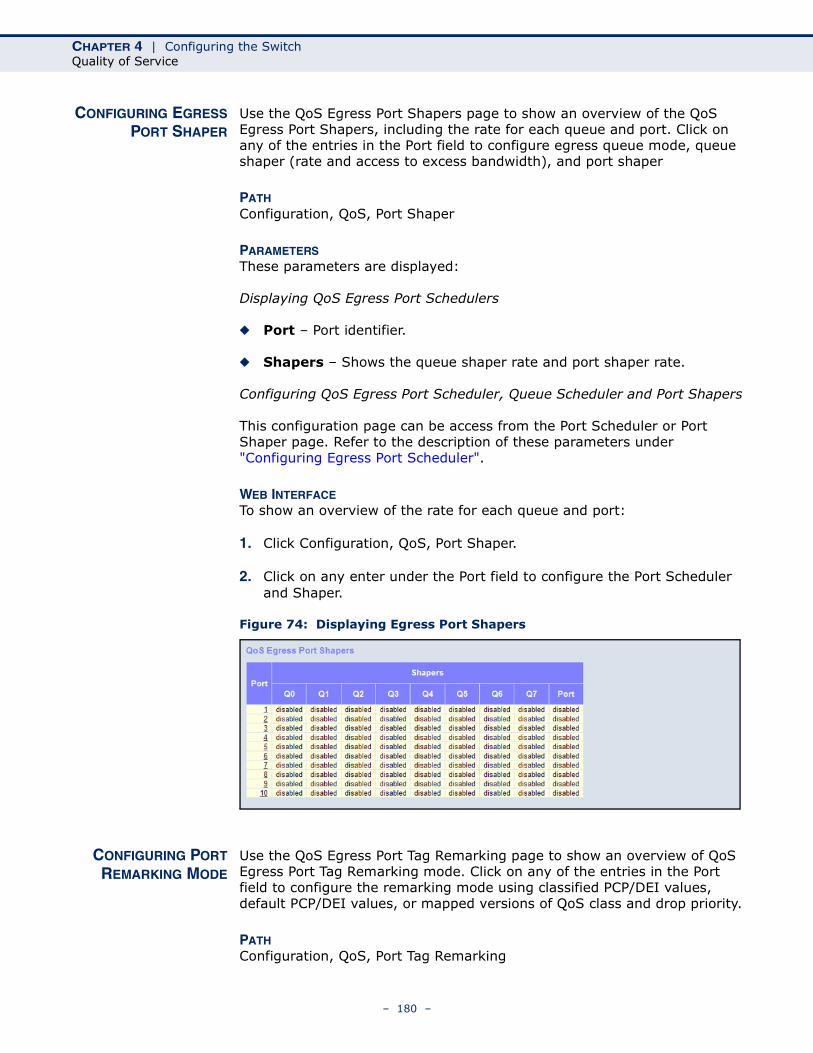
CHAPTER 4 | Configuring the SwitchQuality of Service
CONFIGURING EGRESSPORT SHAPER
Use the QoS Egress Port Shapers page to show an overview of the QoS Egress Port Shapers, including the rate for each queue and port. Click on any of the entries in the Port field to configure egress queue mode, queue shaper (rate and access to excess bandwidth), and port shaper
PATH Configuration, QoS, Port Shaper
PARAMETERSThese parameters are displayed:
Displaying QoS Egress Port Schedulers
◆ Port – Port identifier.
◆ Shapers – Shows the queue shaper rate and port shaper rate.
Configuring QoS Egress Port Scheduler, Queue Scheduler and Port Shapers
This configuration page can be access from the Port Scheduler or Port Shaper page. Refer to the description of these parameters under "Configuring Egress Port Scheduler".
WEB INTERFACETo show an overview of the rate for each queue and port:
1. Click Configuration, QoS, Port Shaper.
2. Click on any enter under the Port field to configure the Port Scheduler and Shaper.
Figure 74: Displaying Egress Port Shapers
CONFIGURING PORTREMARKING MODE
Use the QoS Egress Port Tag Remarking page to show an overview of QoS Egress Port Tag Remarking mode. Click on any of the entries in the Port field to configure the remarking mode using classified PCP/DEI values, default PCP/DEI values, or mapped versions of QoS class and drop priority.
PATH Configuration, QoS, Port Tag Remarking
– 180 –
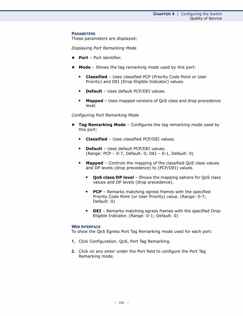
CHAPTER 4 | Configuring the SwitchQuality of Service
PARAMETERSThese parameters are displayed:
Displaying Port Remarking Mode
◆ Port – Port identifier.
◆ Mode – Shows the tag remarking mode used by this port:
■ Classified – Uses classified PCP (Priority Code Point or User Priority) and DEI (Drop Eligible Indicator) values.
■ Default – Uses default PCP/DEI values.
■ Mapped – Uses mapped versions of QoS class and drop precedence level.
Configuring Port Remarking Mode
◆ Tag Remarking Mode – Configures the tag remarking mode used by this port:
■ Classified – Uses classified PCP/DEI values.
■ Default – Uses default PCP/DEI values. (Range: PCP – 0-7, Default: 0; DEI – 0-1, Default: 0)
■ Mapped – Controls the mapping of the classified QoS class values and DP levels (drop precedence) to (PCP/DEI) values.
■ QoS class/DP level – Shows the mapping options for QoS class values and DP levels (drop precedence).
■ PCP – Remarks matching egress frames with the specified Priority Code Point (or User Priority) value. (Range: 0-7; Default: 0)
■ DEI – Remarks matching egress frames with the specified Drop Eligible Indicator. (Range: 0-1; Default: 0)
WEB INTERFACETo show the QoS Egress Port Tag Remarking mode used for each port:
1. Click Configuration, QoS, Port Tag Remarking.
2. Click on any enter under the Port field to configure the Port Tag Remarking mode.
– 181 –
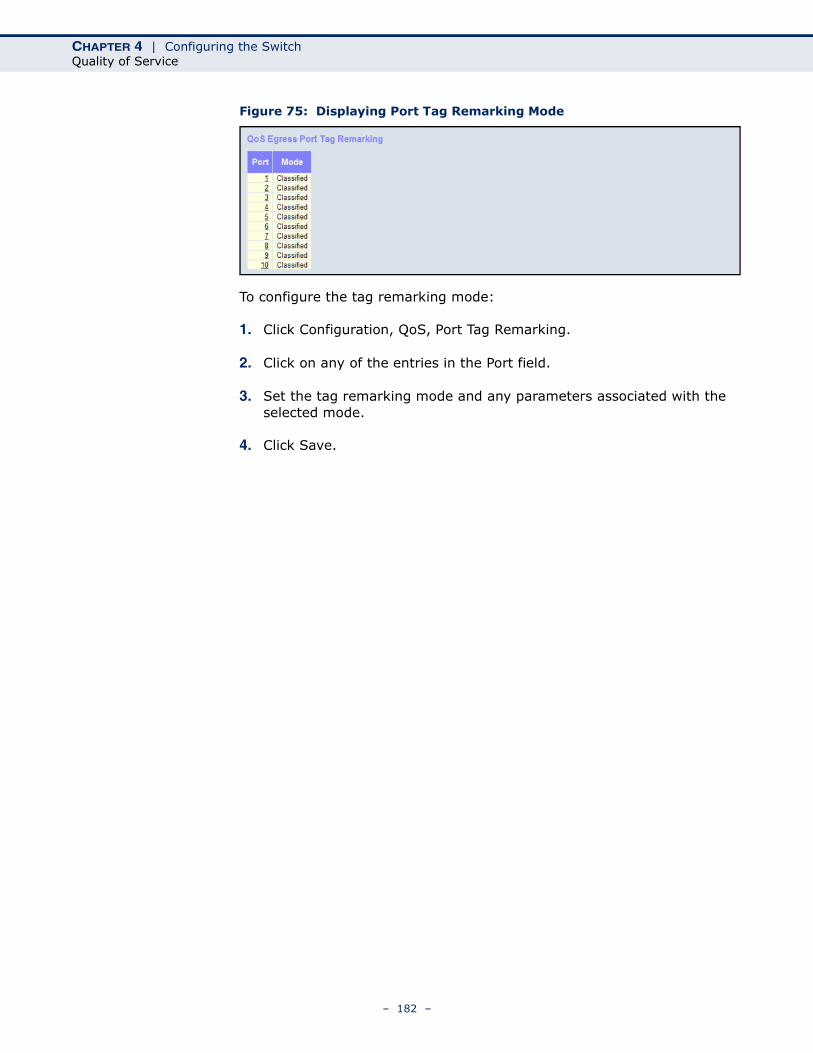
CHAPTER 4 | Configuring the SwitchQuality of Service
Figure 75: Displaying Port Tag Remarking Mode
To configure the tag remarking mode:
1. Click Configuration, QoS, Port Tag Remarking.
2. Click on any of the entries in the Port field.
3. Set the tag remarking mode and any parameters associated with the selected mode.
4. Click Save.
– 182 –
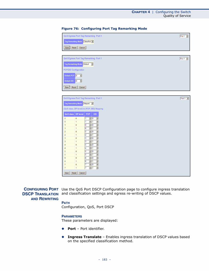
CHAPTER 4 | Configuring the SwitchQuality of Service
Figure 76: Configuring Port Tag Remarking Mode
CONFIGURING PORTDSCP TRANSLATION
AND REWRITING
Use the QoS Port DSCP Configuration page to configure ingress translation and classification settings and egress re-writing of DSCP values.
PATH Configuration, QoS, Port DSCP
PARAMETERSThese parameters are displayed:
◆ Port – Port identifier.
◆ Ingress Translate – Enables ingress translation of DSCP values based on the specified classification method.
– 183 –
CHAPTER 4 | Configuring the SwitchQuality of Service
◆ Ingress Classify – Specifies the classification method:
■ Disable – No Ingress DSCP Classification is performed.
■ DSCP=0 – Classify if incoming DSCP is 0.
■ Selected – Classify only selected DSCP for which classification is enabled in DSCP Translation table (see page 186).
■ All – Classify all DSCP.
◆ Egress Rewrite – Configures port egress rewriting of DSCP values:
■ Disable – Egress rewriting is not performed.
■ Enable – Egress rewriting is performed without remapping.
■ Remap DP Aware – Frame with DSCP from analyzer is remapped and remarked with the remapped DSCP value. Depending on the frame’s DP level, the remapped DSCP value is either taken from the DSCP Translation table, Egress Remap DP0 or DP1 field (see page 186).
■ Remap DP Unaware – Frame with DSCP from analyzer is remapped and remarked with the remapped DSCP value. The remapped DSCP value is always taken from the DSCP Translation table, Egress Remap DP0 field (see page 186).
WEB INTERFACETo configure ingress translation and classification settings and egress re-writing of DSCP values:
1. Click Configuration, QoS, Port DSCP.
2. Set the required ingress translation and egress re-writing parameters.
3. Click Save.
– 184 –
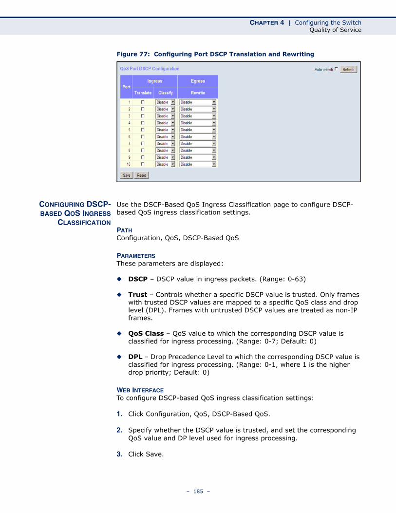
CHAPTER 4 | Configuring the SwitchQuality of Service
Figure 77: Configuring Port DSCP Translation and Rewriting
CONFIGURING DSCP-BASED QOS INGRESS
CLASSIFICATION
Use the DSCP-Based QoS Ingress Classification page to configure DSCP-based QoS ingress classification settings.
PATH Configuration, QoS, DSCP-Based QoS
PARAMETERSThese parameters are displayed:
◆ DSCP – DSCP value in ingress packets. (Range: 0-63)
◆ Trust – Controls whether a specific DSCP value is trusted. Only frames with trusted DSCP values are mapped to a specific QoS class and drop level (DPL). Frames with untrusted DSCP values are treated as non-IP frames.
◆ QoS Class – QoS value to which the corresponding DSCP value is classified for ingress processing. (Range: 0-7; Default: 0)
◆ DPL – Drop Precedence Level to which the corresponding DSCP value is classified for ingress processing. (Range: 0-1, where 1 is the higher drop priority; Default: 0)
WEB INTERFACETo configure DSCP-based QoS ingress classification settings:
1. Click Configuration, QoS, DSCP-Based QoS.
2. Specify whether the DSCP value is trusted, and set the corresponding QoS value and DP level used for ingress processing.
3. Click Save.
– 185 –
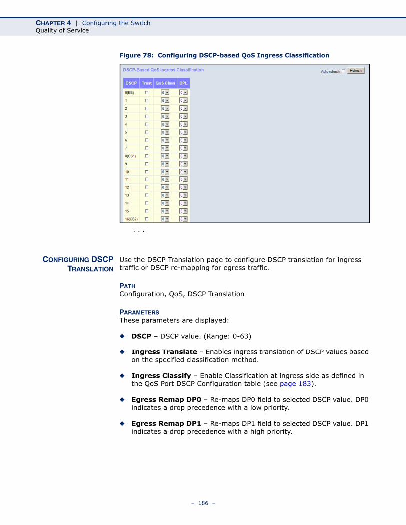
CHAPTER 4 | Configuring the SwitchQuality of Service
Figure 78: Configuring DSCP-based QoS Ingress Classification
CONFIGURING DSCPTRANSLATION
Use the DSCP Translation page to configure DSCP translation for ingress traffic or DSCP re-mapping for egress traffic.
PATH Configuration, QoS, DSCP Translation
PARAMETERSThese parameters are displayed:
◆ DSCP – DSCP value. (Range: 0-63)
◆ Ingress Translate – Enables ingress translation of DSCP values based on the specified classification method.
◆ Ingress Classify – Enable Classification at ingress side as defined in the QoS Port DSCP Configuration table (see page 183).
◆ Egress Remap DP0 – Re-maps DP0 field to selected DSCP value. DP0 indicates a drop precedence with a low priority.
◆ Egress Remap DP1 – Re-maps DP1 field to selected DSCP value. DP1 indicates a drop precedence with a high priority.
. . .
– 186 –
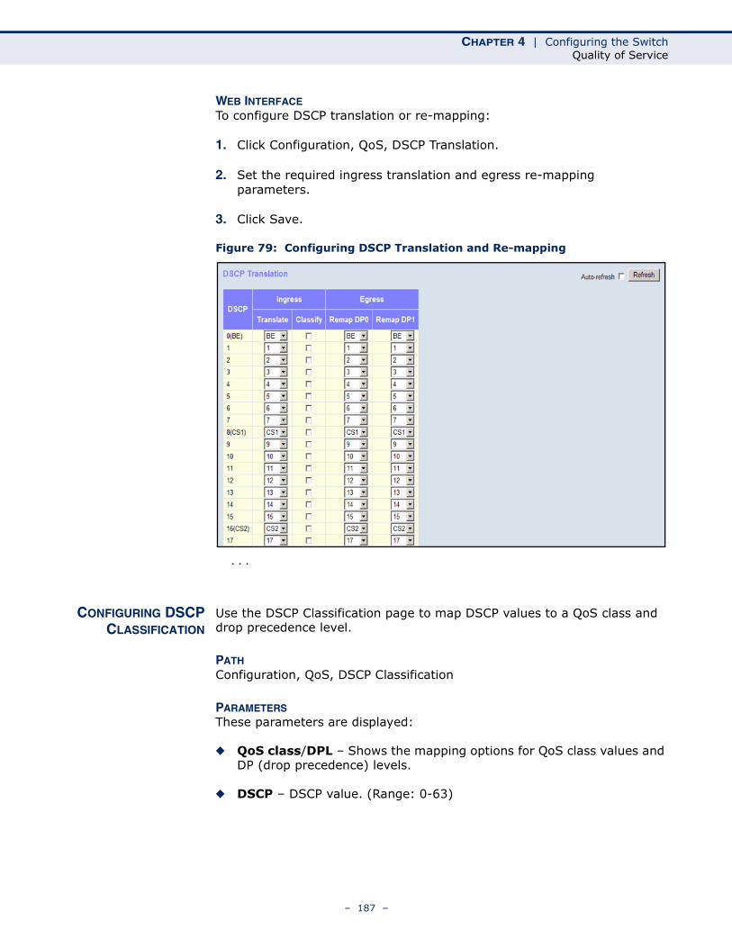
CHAPTER 4 | Configuring the SwitchQuality of Service
WEB INTERFACETo configure DSCP translation or re-mapping:
1. Click Configuration, QoS, DSCP Translation.
2. Set the required ingress translation and egress re-mapping parameters.
3. Click Save.
Figure 79: Configuring DSCP Translation and Re-mapping
CONFIGURING DSCPCLASSIFICATION
Use the DSCP Classification page to map DSCP values to a QoS class and drop precedence level.
PATH Configuration, QoS, DSCP Classification
PARAMETERSThese parameters are displayed:
◆ QoS class/DPL – Shows the mapping options for QoS class values and DP (drop precedence) levels.
◆ DSCP – DSCP value. (Range: 0-63)
. . .
– 187 –
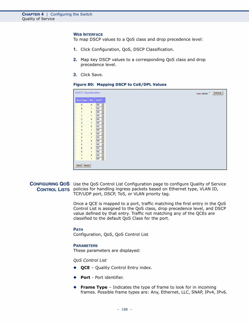
CHAPTER 4 | Configuring the SwitchQuality of Service
WEB INTERFACETo map DSCP values to a QoS class and drop precedence level:
1. Click Configuration, QoS, DSCP Classification.
2. Map key DSCP values to a corresponding QoS class and drop precedence level.
3. Click Save.
Figure 80: Mapping DSCP to CoS/DPL Values
CONFIGURING QOSCONTROL LISTS
Use the QoS Control List Configuration page to configure Quality of Service policies for handling ingress packets based on Ethernet type, VLAN ID, TCP/UDP port, DSCP, ToS, or VLAN priority tag.
Once a QCE is mapped to a port, traffic matching the first entry in the QoS Control List is assigned to the QoS class, drop precedence level, and DSCP value defined by that entry. Traffic not matching any of the QCEs are classified to the default QoS Class for the port.
PATH Configuration, QoS, QoS Control List
PARAMETERSThese parameters are displayed:
QoS Control List
◆ QCE – Quality Control Entry index.
◆ Port - Port identifier.
◆ Frame Type – Indicates the type of frame to look for in incoming frames. Possible frame types are: Any, Ethernet, LLC, SNAP, IPv4, IPv6.
– 188 –
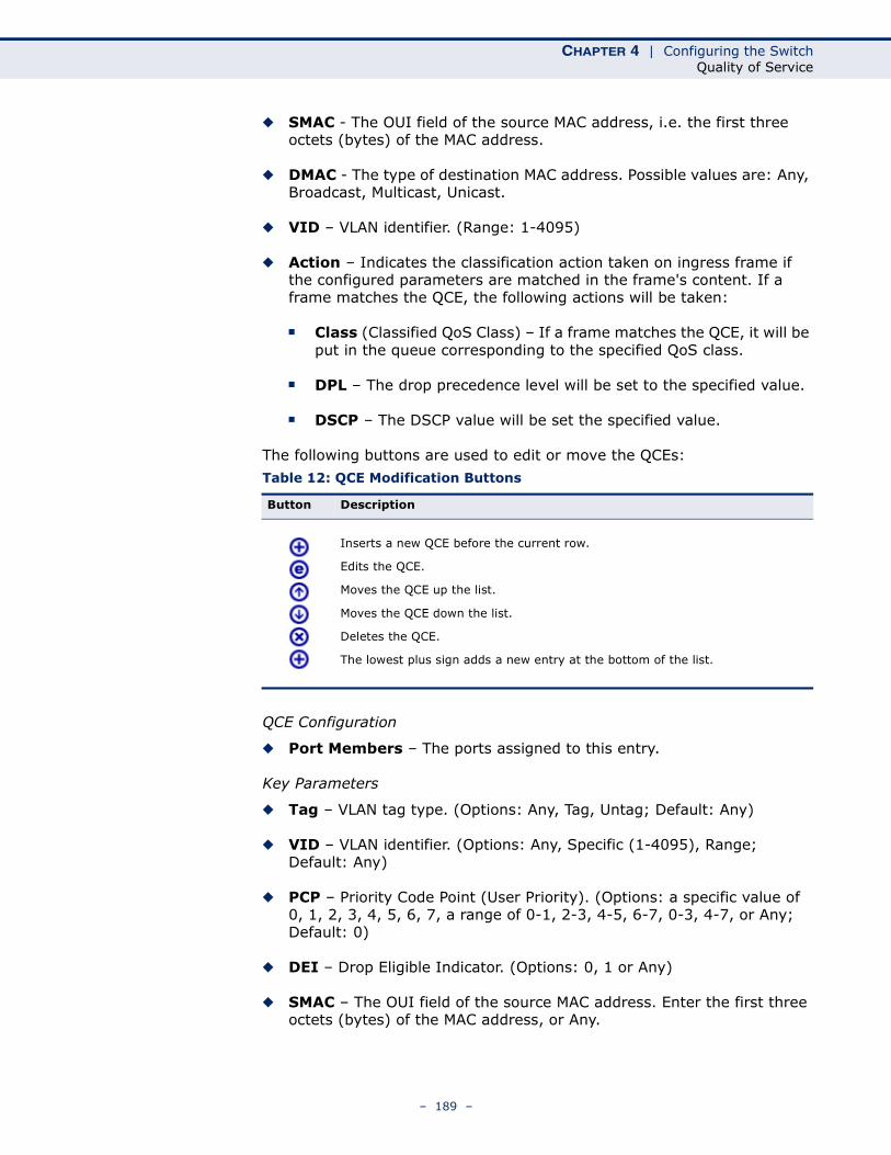
CHAPTER 4 | Configuring the SwitchQuality of Service
◆ SMAC - The OUI field of the source MAC address, i.e. the first three octets (bytes) of the MAC address.
◆ DMAC - The type of destination MAC address. Possible values are: Any, Broadcast, Multicast, Unicast.
◆ VID – VLAN identifier. (Range: 1-4095)
◆ Action – Indicates the classification action taken on ingress frame if the configured parameters are matched in the frame's content. If a frame matches the QCE, the following actions will be taken:
■ Class (Classified QoS Class) – If a frame matches the QCE, it will be put in the queue corresponding to the specified QoS class.
■ DPL – The drop precedence level will be set to the specified value.
■ DSCP – The DSCP value will be set the specified value.
The following buttons are used to edit or move the QCEs:
QCE Configuration
◆ Port Members – The ports assigned to this entry.
Key Parameters
◆ Tag – VLAN tag type. (Options: Any, Tag, Untag; Default: Any)
◆ VID – VLAN identifier. (Options: Any, Specific (1-4095), Range; Default: Any)
◆ PCP – Priority Code Point (User Priority). (Options: a specific value of 0, 1, 2, 3, 4, 5, 6, 7, a range of 0-1, 2-3, 4-5, 6-7, 0-3, 4-7, or Any; Default: 0)
◆ DEI – Drop Eligible Indicator. (Options: 0, 1 or Any)
◆ SMAC – The OUI field of the source MAC address. Enter the first three octets (bytes) of the MAC address, or Any.
Table 12: QCE Modification Buttons
Button Description
Inserts a new QCE before the current row.
Edits the QCE.
Moves the QCE up the list.
Moves the QCE down the list.
Deletes the QCE.
The lowest plus sign adds a new entry at the bottom of the list.
– 189 –
CHAPTER 4 | Configuring the SwitchQuality of Service
◆ DMAC Type – The type of destination MAC address. (Options: Any, BC (Broadcast), MC (Multicast), UC (Unicast)
◆ Frame Type – The supported types are listed below:
■ Any – Allow all types of frames.
■ Ethernet – This option can only be used to filter Ethernet II formatted packets. (Options: Any, Specific – 600-ffff hex; Default: ffff)
Note that 800 (IPv4) and 86DD (IPv6) are excluded.
A detailed listing of Ethernet protocol types can be found in RFC 1060. A few of the more common types include 0800 (IP), 0806 (ARP), 8137 (IPX).
■ LLC – Link Logical Control includes the following settings:
■ SSAP Address – Source Service Access Point address. (Options: Any, Specific (0x00-0xff); Default: 0xff)
■ DSAP Address – Destination Service Access Point address. (Options: Any, Specific (0x00-0xff); Default: 0xff)
■ Control – Control field may contain command, response, or sequence information depending on whether the LLC frame type is Unnumbered, Supervisory, or Information. (Options: Any, Specific (0x00-0xff); Default: 0xff)
■ SNAP – SubNetwork Access Protocol can be distinguished by an OUI and a Protocol ID. (Options for PID: Any, Specific (0x00-0xffff); Default: Any)
If the OUI is hexadecimal 000000, the protocol ID is the Ethernet type (EtherType) field value for the protocol running on top of SNAP. If the OUI is that of a particular organization, the protocol ID is a value assigned by that organization to the protocol running on top of SNAP.
In other words, if value of the OUI field is 00-00-00, then value of the PID will be etherType (0x0600-0xffff), and if value of the OUI is other than 00-00-00, then valid value of the PID will be any value from 0x0000 to 0xffff.
■ IPv4 – IPv4 frame type includes the following settings:
■ Protocol – IP protocol number. (Options: Any, UDP, TCP, or Other (0-255))
■ Source IP – Source IP address. (Options: Any, Specific)
To configure a specific source IP address, enter both the address and mask format. The address and mask must be in the format x.y.z.w where x, y, z, and w are decimal numbers between 0 and 255. When the mask is converted to a 32-bit binary string and read from left to right, all bits following the first zero must also be zero
– 190 –
CHAPTER 4 | Configuring the SwitchQuality of Service
■ IP Fragment – Indicates whether or not fragmented packets are accepted. (Options: Any, Yes, No; Default: Any)
Datagrams may be fragmented to ensure they can pass through a network device which uses a maximum transfer unit smaller than the original packet’s size.
■ DSCP – Diffserv Code Point value. (Options: Any, specific value of 0-63, BE, CS1-CS7, EF or AF11-AF43, or Range; Default: Any)
■ IPv6 – IPv6 frame type includes the same settings as those used for IPv4, except for the Source IP. When configuring a specific IPv6 source address, enter the least significant 32 bits (a.b.c.d) using the same type of mask as that used for an IPv4 address.
■ Sport – Source TCP/UDP port. (Any, Specific/Range: 0-65535)
■ Dport – Destination TCP/UDP port. (Any, Specific/Range: 0-65535)
Action Parameters
◆ Action – Indicates the classification action taken on ingress frame if the configured parameters are matched in the frame's content. If a frame matches the QCE, the following actions will be taken:
◆ Class (Classified QoS Class) – If a frame matches the QCE, it will be put in the queue corresponding to the specified QoS class, or placed in a queue based on basic classification rules. (Options: 0-7, Default (use basic classification); Default setting: 0)
◆ DPL – The drop precedence level will be set to the specified value or left unchanged. (Options: 0-1, Default; Default setting: Default)
◆ DSCP – The DSCP value will be set to the specified value or left unchanged. (Options: 0-63, BE, CS1-CS7, Default (not changed); Default setting: Default)
WEB INTERFACETo configure QoS Control Lists:
1. Click Configuration, QoS, QoS Control List.
2. Click the button to add a new QCE, or use the other QCE modification buttons to specify the editing action (i.e., edit, delete, or moving the relative position of entry in the list).
3. When editing an entry on the QCE Configuration page, specify the relevant criteria to be matched, and the response to a match.
4. Click Save.
– 191 –
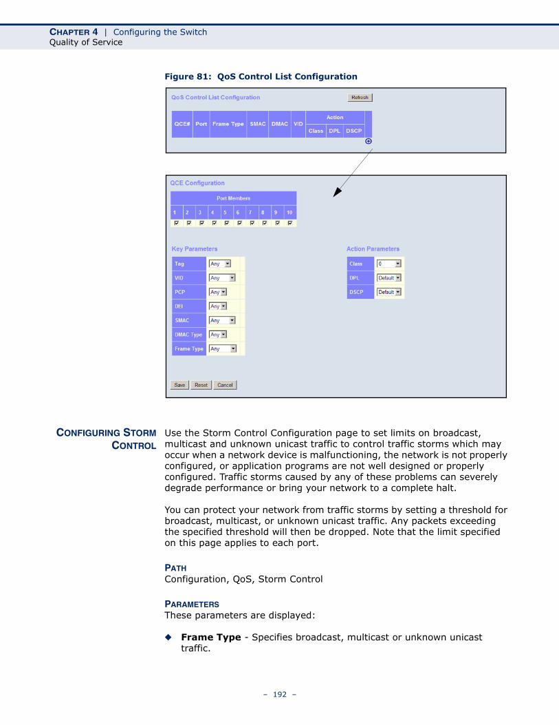
CHAPTER 4 | Configuring the SwitchQuality of Service
Figure 81: QoS Control List Configuration
CONFIGURING STORMCONTROL
Use the Storm Control Configuration page to set limits on broadcast, multicast and unknown unicast traffic to control traffic storms which may occur when a network device is malfunctioning, the network is not properly configured, or application programs are not well designed or properly configured. Traffic storms caused by any of these problems can severely degrade performance or bring your network to a complete halt.
You can protect your network from traffic storms by setting a threshold for broadcast, multicast, or unknown unicast traffic. Any packets exceeding the specified threshold will then be dropped. Note that the limit specified on this page applies to each port.
PATH Configuration, QoS, Storm Control
PARAMETERSThese parameters are displayed:
◆ Frame Type - Specifies broadcast, multicast or unknown unicast traffic.
– 192 –
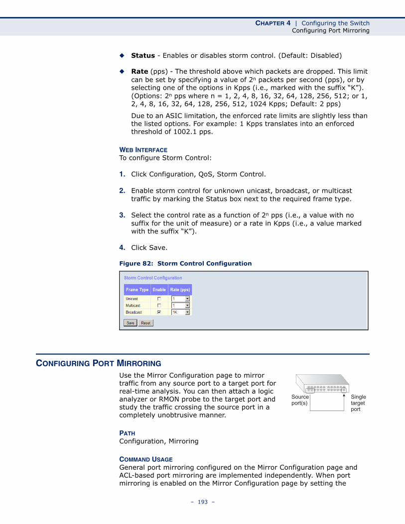
CHAPTER 4 | Configuring the SwitchConfiguring Port Mirroring
◆ Status - Enables or disables storm control. (Default: Disabled)
◆ Rate (pps) - The threshold above which packets are dropped. This limit can be set by specifying a value of 2n packets per second (pps), or by selecting one of the options in Kpps (i.e., marked with the suffix “K”). (Options: 2n pps where n = 1, 2, 4, 8, 16, 32, 64, 128, 256, 512; or 1, 2, 4, 8, 16, 32, 64, 128, 256, 512, 1024 Kpps; Default: 2 pps)
Due to an ASIC limitation, the enforced rate limits are slightly less than the listed options. For example: 1 Kpps translates into an enforced threshold of 1002.1 pps.
WEB INTERFACETo configure Storm Control:
1. Click Configuration, QoS, Storm Control.
2. Enable storm control for unknown unicast, broadcast, or multicast traffic by marking the Status box next to the required frame type.
3. Select the control rate as a function of 2n pps (i.e., a value with no suffix for the unit of measure) or a rate in Kpps (i.e., a value marked with the suffix “K”).
4. Click Save.
Figure 82: Storm Control Configuration
CONFIGURING PORT MIRRORING
Use the Mirror Configuration page to mirror traffic from any source port to a target port for real-time analysis. You can then attach a logic analyzer or RMON probe to the target port and study the traffic crossing the source port in a completely unobtrusive manner.
PATH Configuration, Mirroring
COMMAND USAGEGeneral port mirroring configured on the Mirror Configuration page and ACL-based port mirroring are implemented independently. When port mirroring is enabled on the Mirror Configuration page by setting the
Sourceport(s)
Singletargetport
– 193 –
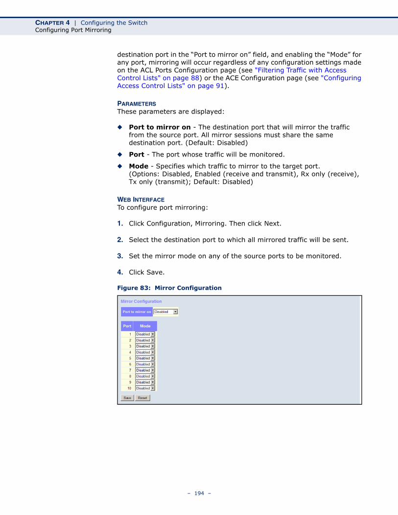
CHAPTER 4 | Configuring the SwitchConfiguring Port Mirroring
destination port in the “Port to mirror on” field, and enabling the “Mode” for any port, mirroring will occur regardless of any configuration settings made on the ACL Ports Configuration page (see "Filtering Traffic with Access Control Lists" on page 88) or the ACE Configuration page (see "Configuring Access Control Lists" on page 91).
PARAMETERSThese parameters are displayed:
◆ Port to mirror on - The destination port that will mirror the traffic from the source port. All mirror sessions must share the same destination port. (Default: Disabled)
◆ Port - The port whose traffic will be monitored.
◆ Mode - Specifies which traffic to mirror to the target port. (Options: Disabled, Enabled (receive and transmit), Rx only (receive), Tx only (transmit); Default: Disabled)
WEB INTERFACETo configure port mirroring:
1. Click Configuration, Mirroring. Then click Next.
2. Select the destination port to which all mirrored traffic will be sent.
3. Set the mirror mode on any of the source ports to be monitored.
4. Click Save.
Figure 83: Mirror Configuration
– 194 –
CHAPTER 4 | Configuring the SwitchConfiguring UPnP
CONFIGURING UPNPUniversal Plug and Play (UPnP) is a set of protocols that allows devices to connect seamlessly and simplifies the deployment of home and office networks. UPnP achieves this by issuing UPnP device control protocols designed upon open, Internet-based communication standards.
The first step in UPnP networking is discovery. When a device is added to the network, the UPnP discovery protocol allows that device to broadcast its services to control points on the network. Similarly, when a control point is added to the network, the UPnP discovery protocol allows that control point to search for UPnP enabled devices on the network.
Once a control point has discovered a device its next step is to learn more about the device and its capabilities by retrieving the device's description from the URL provided by the device in the discovery message. After a control point has retrieved a description of the device, it can send actions to the device's service. To do this, a control point sends a suitable control message to the control URL for the service (provided in the device description).
When a device is known to the control point, periodic event notification messages are sent. A UPnP description for a service includes a list of actions the service responds to and a list of variables that model the state of the service at run time.
If a device has a URL for presentation, then the control point can retrieve a page from this URL, load the page into a web browser, and depending on the capabilities of the page, allow a user to control the device and/or view device status.
Using UPnP under Windows XP - To access or manage the switch with the aid of UPnP under Windows XP, open My Network Places in the Explore file manager. An entry for “SM8TAF2DPA” will appear in the list of discovered devices. Double-click on this entry to access the switch's web management interface. Or right-click on the entry and select “Properties” to display a list of device attributes advertised through UPnP.
PARAMETERSThese parameters are displayed:
◆ Mode - Enables/disables UPnP on the device. (Default: Disabled)
◆ TTL - Sets the time-to-live (TTL) value for UPnP messages transmitted by the switch. (Range: 4-255; Default: 4)
◆ Advertising Duration - The duration, carried in Simple Service Discover Protocol (SSDP) packets, which informs a control point or control points how often it or they should receive a SSDP advertisement message from this switch. Due to the unreliable nature of UDP, the switch sends SSDP messages periodically at the interval one-half of the advertising duration minus 30 seconds. (Range: 100-86400 seconds; Default: 100 seconds)
– 195 –
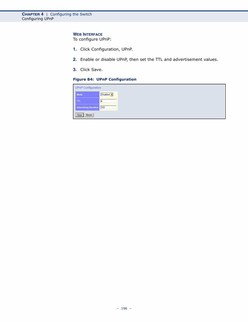
CHAPTER 4 | Configuring the SwitchConfiguring UPnP
WEB INTERFACETo configure UPnP:
1. Click Configuration, UPnP.
2. Enable or disable UPnP, then set the TTL and advertisement values.
3. Click Save.
Figure 84: UPnP Configuration
– 196 –
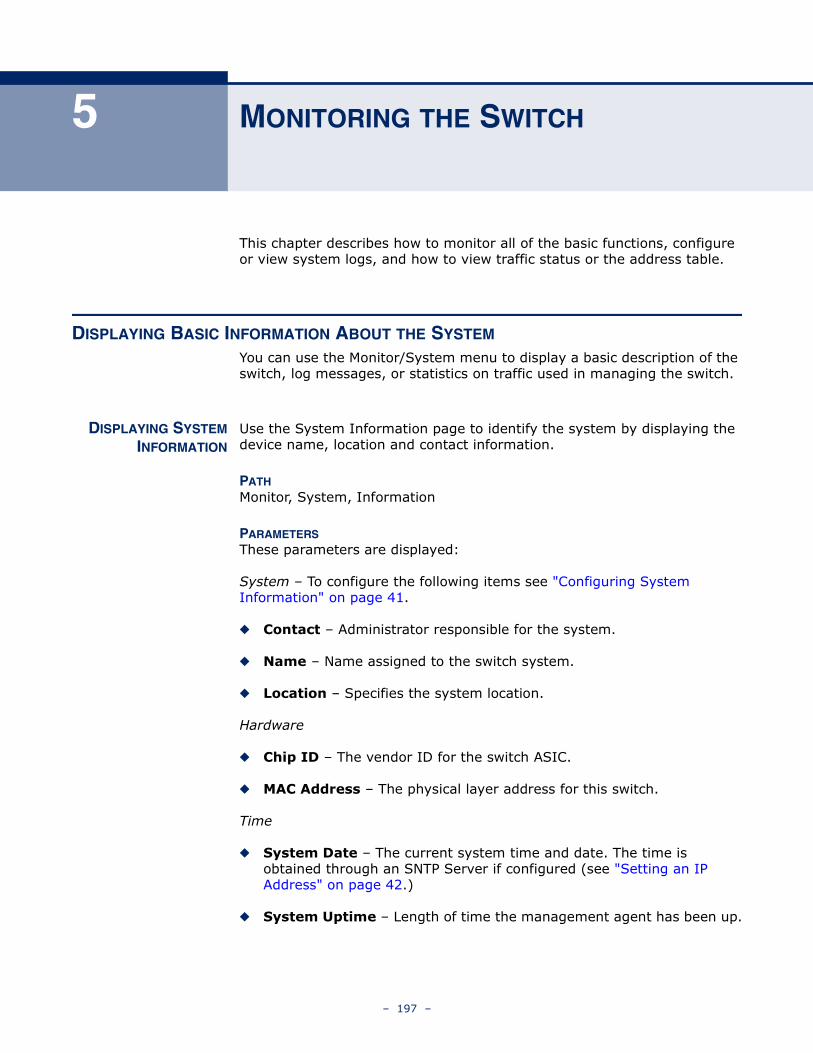
5 MONITORING THE SWITCH
This chapter describes how to monitor all of the basic functions, configure or view system logs, and how to view traffic status or the address table.
DISPLAYING BASIC INFORMATION ABOUT THE SYSTEM
You can use the Monitor/System menu to display a basic description of the switch, log messages, or statistics on traffic used in managing the switch.
DISPLAYING SYSTEMINFORMATION
Use the System Information page to identify the system by displaying the device name, location and contact information.
PATHMonitor, System, Information
PARAMETERSThese parameters are displayed:
System – To configure the following items see "Configuring System Information" on page 41.
◆ Contact – Administrator responsible for the system.
◆ Name – Name assigned to the switch system.
◆ Location – Specifies the system location.
Hardware
◆ Chip ID – The vendor ID for the switch ASIC.
◆ MAC Address – The physical layer address for this switch.
Time
◆ System Date – The current system time and date. The time is obtained through an SNTP Server if configured (see "Setting an IP Address" on page 42.)
◆ System Uptime – Length of time the management agent has been up.
– 197 –
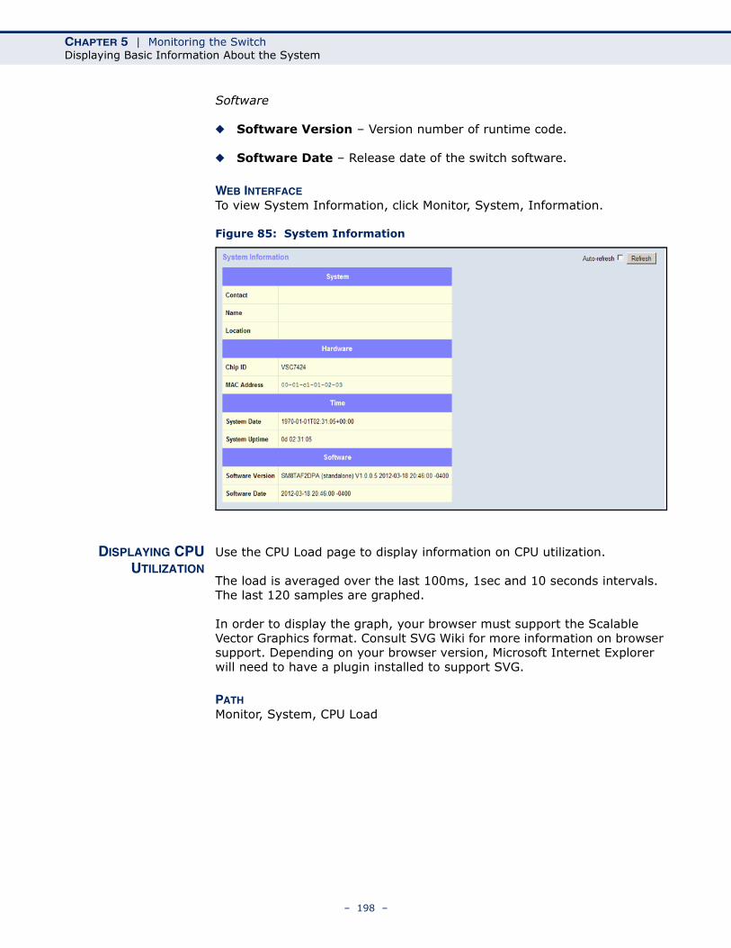
CHAPTER 5 | Monitoring the SwitchDisplaying Basic Information About the System
Software
◆ Software Version – Version number of runtime code.
◆ Software Date – Release date of the switch software.
WEB INTERFACETo view System Information, click Monitor, System, Information.
Figure 85: System Information
DISPLAYING CPUUTILIZATION
Use the CPU Load page to display information on CPU utilization.
The load is averaged over the last 100ms, 1sec and 10 seconds intervals. The last 120 samples are graphed.
In order to display the graph, your browser must support the Scalable Vector Graphics format. Consult SVG Wiki for more information on browser support. Depending on your browser version, Microsoft Internet Explorer will need to have a plugin installed to support SVG.
PATHMonitor, System, CPU Load
– 198 –
CHAPTER 5 | Monitoring the SwitchDisplaying Basic Information About the System
WEB INTERFACETo display CPU utilization:
1. Click System, then CPU Load.
Figure 86: CPU Load
DISPLAYING LOGMESSAGES
Use the System Log Information page to scroll through the logged system and event messages.
PATHMonitor, System, CPU Load
PARAMETERSThese parameters are displayed:
Display Filter
◆ Level – Specifies the type of log messages to display.
■ Info – Informational messages only.
■ Warning – Warning conditions.
■ Error – Error conditions.
■ All – All levels.
◆ Start from ID – The error ID from which to start the display.
◆ with # entries per page – The number of entries to display per page.
Table Headings
◆ ID – Error ID.
◆ Level – Error level as described above.
– 199 –
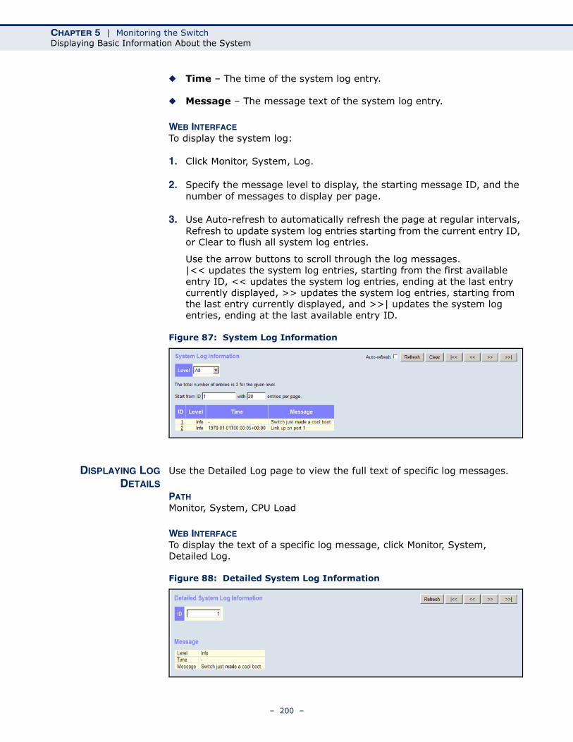
CHAPTER 5 | Monitoring the SwitchDisplaying Basic Information About the System
◆ Time – The time of the system log entry.
◆ Message – The message text of the system log entry.
WEB INTERFACETo display the system log:
1. Click Monitor, System, Log.
2. Specify the message level to display, the starting message ID, and the number of messages to display per page.
3. Use Auto-refresh to automatically refresh the page at regular intervals, Refresh to update system log entries starting from the current entry ID, or Clear to flush all system log entries.
Use the arrow buttons to scroll through the log messages. |<< updates the system log entries, starting from the first available entry ID, << updates the system log entries, ending at the last entry currently displayed, >> updates the system log entries, starting from the last entry currently displayed, and >>| updates the system log entries, ending at the last available entry ID.
Figure 87: System Log Information
DISPLAYING LOGDETAILS
Use the Detailed Log page to view the full text of specific log messages.
PATHMonitor, System, CPU Load
WEB INTERFACETo display the text of a specific log message, click Monitor, System, Detailed Log.
Figure 88: Detailed System Log Information
– 200 –
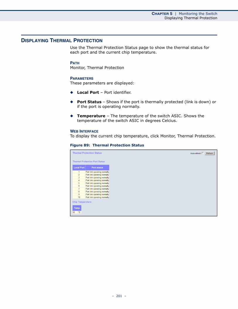
CHAPTER 5 | Monitoring the SwitchDisplaying Thermal Protection
DISPLAYING THERMAL PROTECTION
Use the Thermal Protection Status page to show the thermal status for each port and the current chip temperature.
PATH Monitor, Thermal Protection
PARAMETERSThese parameters are displayed:
◆ Local Port – Port identifier.
◆ Port Status – Shows if the port is thermally protected (link is down) or if the port is operating normally.
◆ Temperature – The temperature of the switch ASIC. Shows the temperature of the switch ASIC in degrees Celcius.
WEB INTERFACETo display the current chip temperature, click Monitor, Thermal Protection.
Figure 89: Thermal Protection Status
– 201 –
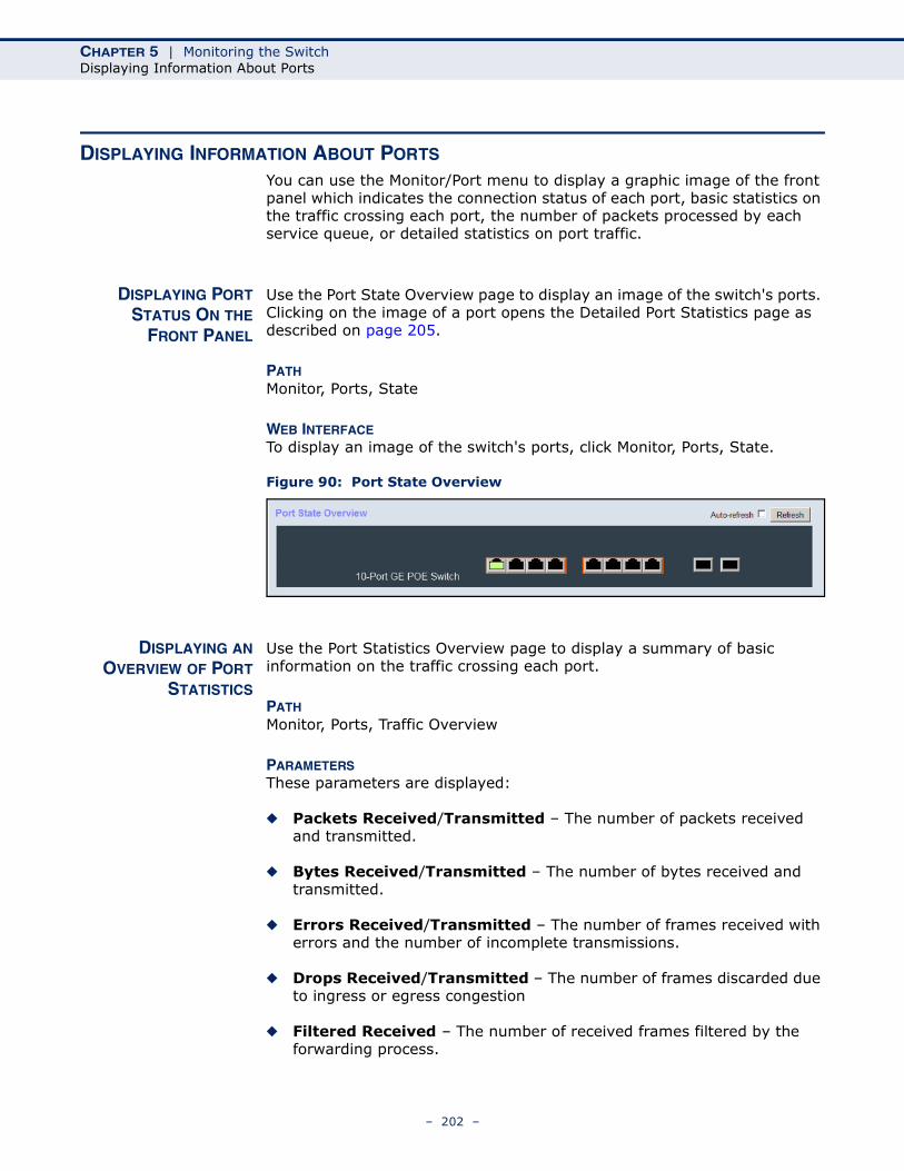
CHAPTER 5 | Monitoring the SwitchDisplaying Information About Ports
DISPLAYING INFORMATION ABOUT PORTS
You can use the Monitor/Port menu to display a graphic image of the front panel which indicates the connection status of each port, basic statistics on the traffic crossing each port, the number of packets processed by each service queue, or detailed statistics on port traffic.
DISPLAYING PORTSTATUS ON THE
FRONT PANEL
Use the Port State Overview page to display an image of the switch's ports. Clicking on the image of a port opens the Detailed Port Statistics page as described on page 205.
PATH Monitor, Ports, State
WEB INTERFACETo display an image of the switch's ports, click Monitor, Ports, State.
Figure 90: Port State Overview
DISPLAYING ANOVERVIEW OF PORT
STATISTICS
Use the Port Statistics Overview page to display a summary of basic information on the traffic crossing each port.
PATH Monitor, Ports, Traffic Overview
PARAMETERSThese parameters are displayed:
◆ Packets Received/Transmitted – The number of packets received and transmitted.
◆ Bytes Received/Transmitted – The number of bytes received and transmitted.
◆ Errors Received/Transmitted – The number of frames received with errors and the number of incomplete transmissions.
◆ Drops Received/Transmitted – The number of frames discarded due to ingress or egress congestion
◆ Filtered Received – The number of received frames filtered by the forwarding process.
– 202 –

CHAPTER 5 | Monitoring the SwitchDisplaying Information About Ports
WEB INTERFACETo display a summary of port statistics, click Monitor, Ports, Traffic Overview.
Figure 91: Port Statistics Overview
DISPLAYING QOSSTATISTICS
Use the Queuing Counters page to display the number of packets processed by each service queue.
PATH Monitor, Ports, QoS Statistics
PARAMETERSThese parameters are displayed:
◆ Port – Port identifier.
◆ Q# Receive/Transmit – The number of packets received and transmitted through the indicated queue.
WEB INTERFACETo display the queue counters, click Monitor, Ports, QoS Statistics.
Figure 92: Queueing Counters
– 203 –
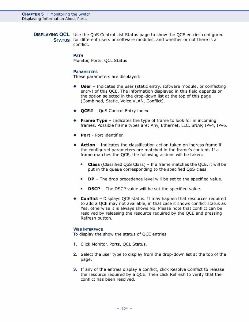
CHAPTER 5 | Monitoring the SwitchDisplaying Information About Ports
DISPLAYING QCLSTATUS
Use the QoS Control List Status page to show the QCE entries configured for different users or software modules, and whether or not there is a conflict.
PATH Monitor, Ports, QCL Status
PARAMETERSThese parameters are displayed:
◆ User – Indicates the user (static entry, software module, or conflicting entry) of this QCE. The information displayed in this field depends on the option selected in the drop-down list at the top of this page (Combined, Static, Voice VLAN, Conflict).
◆ QCE# – QoS Control Entry index.
◆ Frame Type – Indicates the type of frame to look for in incoming frames. Possible frame types are: Any, Ethernet, LLC, SNAP, IPv4, IPv6.
◆ Port - Port identifier.
◆ Action – Indicates the classification action taken on ingress frame if the configured parameters are matched in the frame's content. If a frame matches the QCE, the following actions will be taken:
■ Class (Classified QoS Class) – If a frame matches the QCE, it will be put in the queue corresponding to the specified QoS class.
■ DP – The drop precedence level will be set to the specified value.
■ DSCP – The DSCP value will be set the specified value.
◆ Conflict – Displays QCE status. It may happen that resources required to add a QCE may not available, in that case it shows conflict status as Yes, otherwise it is always shows No. Please note that conflict can be resolved by releasing the resource required by the QCE and pressing Refresh button.
WEB INTERFACETo display the show the status of QCE entries
1. Click Monitor, Ports, QCL Status.
2. Select the user type to display from the drop-down list at the top of the page.
3. If any of the entries display a conflict, click Resolve Conflict to release the resource required by a QCE. Then click Refresh to verify that the conflict has been resolved.
– 204 –
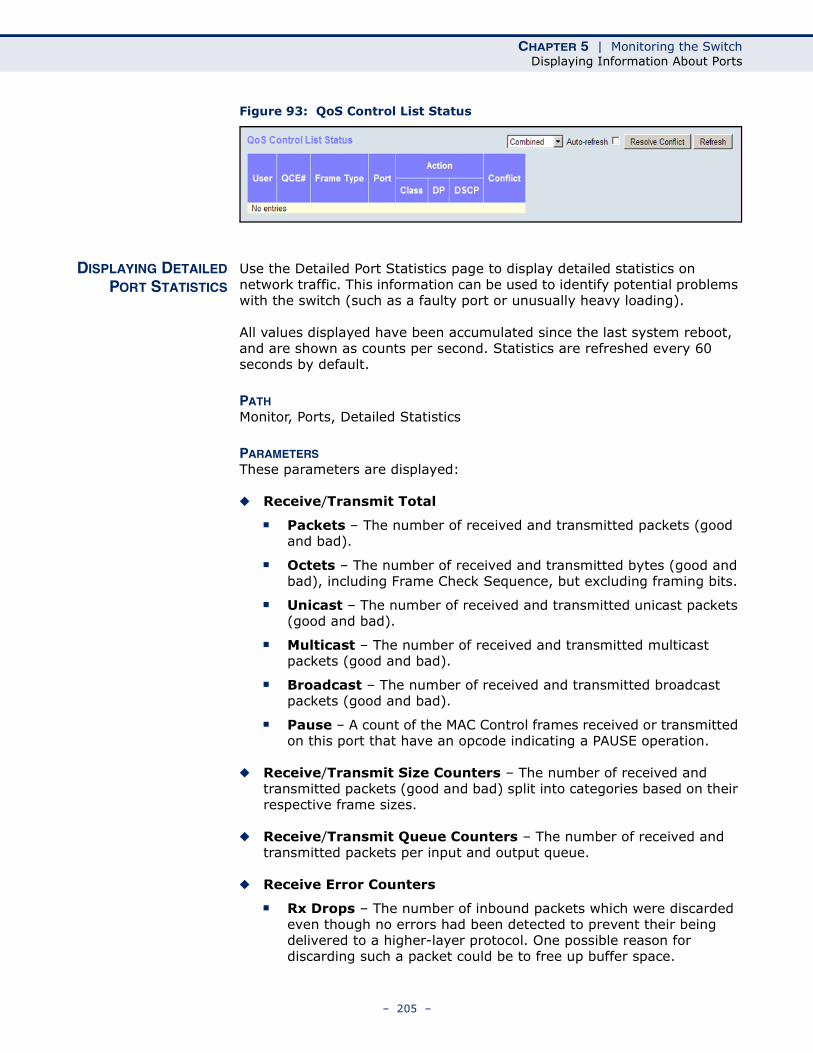
CHAPTER 5 | Monitoring the SwitchDisplaying Information About Ports
Figure 93: QoS Control List Status
DISPLAYING DETAILEDPORT STATISTICS
Use the Detailed Port Statistics page to display detailed statistics on network traffic. This information can be used to identify potential problems with the switch (such as a faulty port or unusually heavy loading).
All values displayed have been accumulated since the last system reboot, and are shown as counts per second. Statistics are refreshed every 60 seconds by default.
PATH Monitor, Ports, Detailed Statistics
PARAMETERSThese parameters are displayed:
◆ Receive/Transmit Total
■ Packets – The number of received and transmitted packets (good and bad).
■ Octets – The number of received and transmitted bytes (good and bad), including Frame Check Sequence, but excluding framing bits.
■ Unicast – The number of received and transmitted unicast packets (good and bad).
■ Multicast – The number of received and transmitted multicast packets (good and bad).
■ Broadcast – The number of received and transmitted broadcast packets (good and bad).
■ Pause – A count of the MAC Control frames received or transmitted on this port that have an opcode indicating a PAUSE operation.
◆ Receive/Transmit Size Counters – The number of received and transmitted packets (good and bad) split into categories based on their respective frame sizes.
◆ Receive/Transmit Queue Counters – The number of received and transmitted packets per input and output queue.
◆ Receive Error Counters
■ Rx Drops – The number of inbound packets which were discarded even though no errors had been detected to prevent their being delivered to a higher-layer protocol. One possible reason for discarding such a packet could be to free up buffer space.
– 205 –

CHAPTER 5 | Monitoring the SwitchDisplaying Information About Ports
■ Rx CRC/Alignment – The number of frames received with CRC or alignment errors.
■ Rx Undersize – The total number of frames received that were less than 64 octets long (excluding framing bits, but including FCS octets) and were otherwise well formed.
■ Rx Oversize – The total number of frames received that were longer than the configured maximum frame length for this port (excluding framing bits, but including FCS octets) and were otherwise well formed.
■ Rx Fragments – The total number of frames received that were less than 64 octets in length (excluding framing bits, but including FCS octets) and had either an FCS or alignment error.
■ Rx Jabber – The total number of frames received that were longer than the configured maximum frame length for this port (excluding framing bits, but including FCS octets), and had either an FCS or alignment error.
■ Rx Filtered – The number of received frames filtered by the forwarding process.
◆ Transmit Error Counters
■ Tx Drops – The number of frames dropped due to output buffer congestion.
■ Tx Late/Exc. Coll. – The number of frames dropped due to late or excessive collisions.
– 206 –
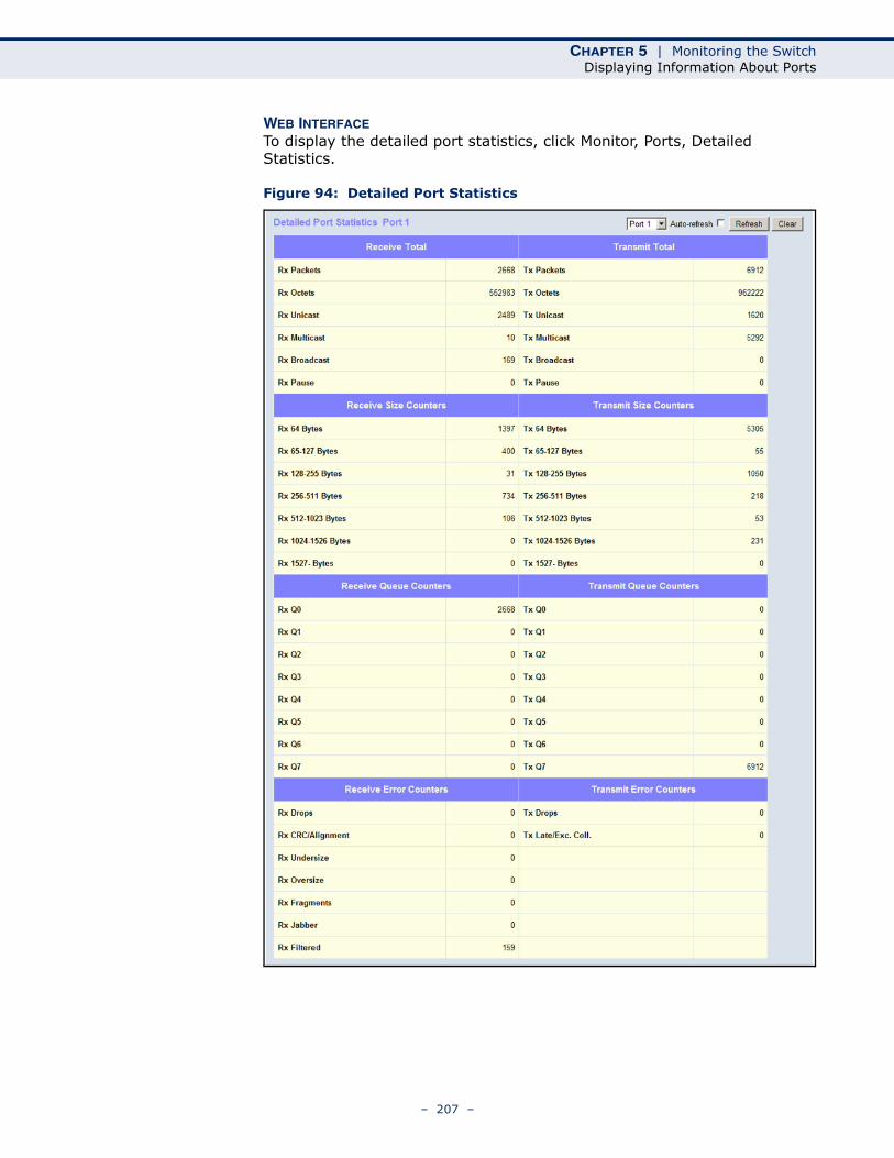
CHAPTER 5 | Monitoring the SwitchDisplaying Information About Ports
WEB INTERFACETo display the detailed port statistics, click Monitor, Ports, Detailed Statistics.
Figure 94: Detailed Port Statistics
– 207 –
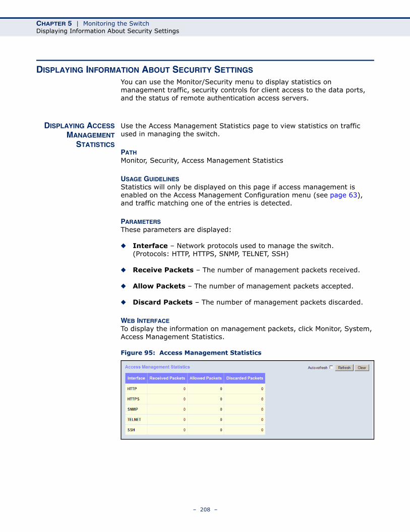
CHAPTER 5 | Monitoring the SwitchDisplaying Information About Security Settings
DISPLAYING INFORMATION ABOUT SECURITY SETTINGS
You can use the Monitor/Security menu to display statistics on management traffic, security controls for client access to the data ports, and the status of remote authentication access servers.
DISPLAYING ACCESSMANAGEMENT
STATISTICS
Use the Access Management Statistics page to view statistics on traffic used in managing the switch.
PATH Monitor, Security, Access Management Statistics
USAGE GUIDELINESStatistics will only be displayed on this page if access management is enabled on the Access Management Configuration menu (see page 63), and traffic matching one of the entries is detected.
PARAMETERSThese parameters are displayed:
◆ Interface – Network protocols used to manage the switch. (Protocols: HTTP, HTTPS, SNMP, TELNET, SSH)
◆ Receive Packets – The number of management packets received.
◆ Allow Packets – The number of management packets accepted.
◆ Discard Packets – The number of management packets discarded.
WEB INTERFACETo display the information on management packets, click Monitor, System, Access Management Statistics.
Figure 95: Access Management Statistics
– 208 –
CHAPTER 5 | Monitoring the SwitchDisplaying Information About Security Settings
DISPLAYINGINFORMATION ABOUT
SWITCH SETTINGS FORPORT SECURITY
Use the Port Security Switch Status page to show information about MAC address learning for each port, including the software module requesting port security services, the service state, the current number of learned addresses, and the maximum number of secure addresses allowed.
Port Security is a module with no direct configuration. Configuration comes indirectly from other software modules – the user modules. When a user module has enabled port security on a port, the port is set up for software-based learning. In this mode, frames from unknown MAC addresses are passed on to the port security module, which in turn asks all user modules whether to allow this new MAC address to be forwarded or blocked. For a MAC address to be set in the forwarding state, all enabled user modules must unanimously agree on allowing the MAC address to forward. If only one chooses to block it, it will be blocked until that user module decides otherwise.
The status page is divided into two sections – one with a legend of user modules that may request port security services, and one with the actual port status.
PATH Monitor, Security, Network, Port Security, Switch
PARAMETERSThese parameters are displayed:
User Module Legend
◆ User Module Name – The full name of a module that may request Port Security services.
◆ Abbr – A one-letter abbreviation of the user module. This is used in the Users column in the port status table.
Port Status
◆ Port – The port number for which the status applies. Click the port number to see the status for this particular port.
◆ Users – Each of the user modules has a column that shows whether that module has enabled Port Security or not. A '-' means that the corresponding user module is not enabled, whereas a letter indicates that the user module abbreviated by that letter has enabled port security.
◆ State – Shows the current state of the port. It can take one of four values:
■ Disabled: No user modules are currently using the Port Security service.
■ Ready: The Port Security service is in use by at least one user module, and is awaiting frames from unknown MAC addresses to arrive.
– 209 –
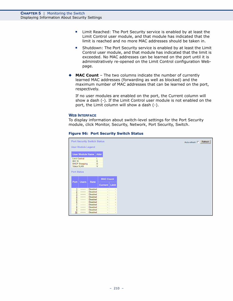
CHAPTER 5 | Monitoring the SwitchDisplaying Information About Security Settings
■ Limit Reached: The Port Security service is enabled by at least the Limit Control user module, and that module has indicated that the limit is reached and no more MAC addresses should be taken in.
■ Shutdown: The Port Security service is enabled by at least the Limit Control user module, and that module has indicated that the limit is exceeded. No MAC addresses can be learned on the port until it is administratively re-opened on the Limit Control configuration Web-page.
◆ MAC Count – The two columns indicate the number of currently learned MAC addresses (forwarding as well as blocked) and the maximum number of MAC addresses that can be learned on the port, respectively.
If no user modules are enabled on the port, the Current column will show a dash (-). If the Limit Control user module is not enabled on the port, the Limit column will show a dash (-).
WEB INTERFACETo display information about switch-level settings for the Port Security module, click Monitor, Security, Network, Port Security, Switch.
Figure 96: Port Security Switch Status
– 210 –
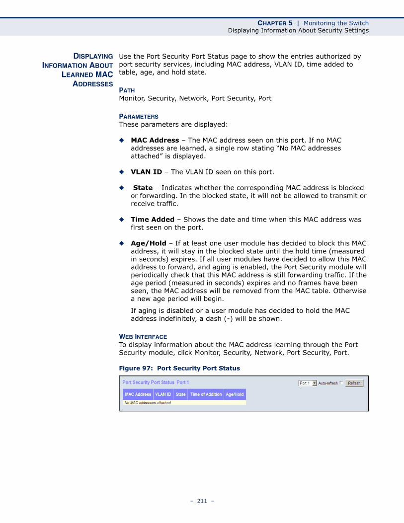
CHAPTER 5 | Monitoring the SwitchDisplaying Information About Security Settings
DISPLAYINGINFORMATION ABOUT
LEARNED MACADDRESSES
Use the Port Security Port Status page to show the entries authorized by port security services, including MAC address, VLAN ID, time added to table, age, and hold state.
PATH Monitor, Security, Network, Port Security, Port
PARAMETERSThese parameters are displayed:
◆ MAC Address – The MAC address seen on this port. If no MAC addresses are learned, a single row stating “No MAC addresses attached” is displayed.
◆ VLAN ID – The VLAN ID seen on this port.
◆ State – Indicates whether the corresponding MAC address is blocked or forwarding. In the blocked state, it will not be allowed to transmit or receive traffic.
◆ Time Added – Shows the date and time when this MAC address was first seen on the port.
◆ Age/Hold – If at least one user module has decided to block this MAC address, it will stay in the blocked state until the hold time (measured in seconds) expires. If all user modules have decided to allow this MAC address to forward, and aging is enabled, the Port Security module will periodically check that this MAC address is still forwarding traffic. If the age period (measured in seconds) expires and no frames have been seen, the MAC address will be removed from the MAC table. Otherwise a new age period will begin.
If aging is disabled or a user module has decided to hold the MAC address indefinitely, a dash (-) will be shown.
WEB INTERFACETo display information about the MAC address learning through the Port Security module, click Monitor, Security, Network, Port Security, Port.
Figure 97: Port Security Port Status
– 211 –
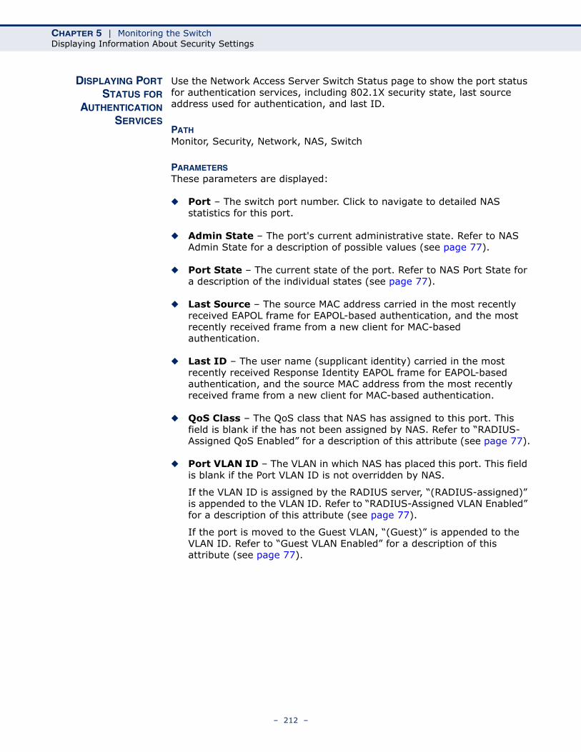
CHAPTER 5 | Monitoring the SwitchDisplaying Information About Security Settings
DISPLAYING PORTSTATUS FOR
AUTHENTICATIONSERVICES
Use the Network Access Server Switch Status page to show the port status for authentication services, including 802.1X security state, last source address used for authentication, and last ID.
PATH Monitor, Security, Network, NAS, Switch
PARAMETERSThese parameters are displayed:
◆ Port – The switch port number. Click to navigate to detailed NAS statistics for this port.
◆ Admin State – The port's current administrative state. Refer to NAS Admin State for a description of possible values (see page 77).
◆ Port State – The current state of the port. Refer to NAS Port State for a description of the individual states (see page 77).
◆ Last Source – The source MAC address carried in the most recently received EAPOL frame for EAPOL-based authentication, and the most recently received frame from a new client for MAC-based authentication.
◆ Last ID – The user name (supplicant identity) carried in the most recently received Response Identity EAPOL frame for EAPOL-based authentication, and the source MAC address from the most recently received frame from a new client for MAC-based authentication.
◆ QoS Class – The QoS class that NAS has assigned to this port. This field is blank if the has not been assigned by NAS. Refer to “RADIUS-Assigned QoS Enabled” for a description of this attribute (see page 77).
◆ Port VLAN ID – The VLAN in which NAS has placed this port. This field is blank if the Port VLAN ID is not overridden by NAS.
If the VLAN ID is assigned by the RADIUS server, “(RADIUS-assigned)” is appended to the VLAN ID. Refer to “RADIUS-Assigned VLAN Enabled” for a description of this attribute (see page 77).
If the port is moved to the Guest VLAN, “(Guest)” is appended to the VLAN ID. Refer to “Guest VLAN Enabled” for a description of this attribute (see page 77).
– 212 –
CHAPTER 5 | Monitoring the SwitchDisplaying Information About Security Settings
WEB INTERFACETo display port status for authentication services, click Monitor, Security, Network, NAS, Switch.
Figure 98: Network Access Server Switch Status
DISPLAYING PORTSTATISTICS FOR
802.1X OR REMOTEAUTHENTICATION
SERVICE
Use the NAS Statistics Port selection page to display authentication statistics for the selected port – either for 802.1X protocol or for the remote authentication server depending on the authentication method.
This page provides detailed NAS statistics for a specific switch port running EAPOL-based IEEE 802.1X authentication. For MAC-based authenticated ports, it shows statistics only for the backend server (RADIUS Authentication Server).
PATH Monitor, Security, Network, NAS, Port
PARAMETERSThese parameters are displayed:
Port State
◆ Admin State – The port's current administrative state. Refer to NAS Admin State for a description of possible values (see page 77).
◆ Port State – The current state of the port. Refer to NAS Port State for a description of the individual states (see page 77).
◆ QoS Class – The QoS class assigned by the RADIUS server. The field is blank if no QoS class is assigned.
◆ Port VLAN ID – The VLAN in which NAS has placed this port. This field is blank if the Port VLAN ID is not overridden by NAS.
If the VLAN ID is assigned by the RADIUS server, “(RADIUS-assigned)” is appended to the VLAN ID. Refer to “RADIUS-Assigned VLAN Enabled” for a description of this attribute (see page 77).
If the port is moved to the Guest VLAN, “(Guest)” is appended to the VLAN ID. Refer to “Guest VLAN Enabled” for a description of this attribute (see page 77).
– 213 –
CHAPTER 5 | Monitoring the SwitchDisplaying Information About Security Settings
Port Counters
Receive EAPOL Counters
◆ Total – The number of valid EAPOL frames of any type that have been received by the switch.
◆ Response ID – The number of valid EAPOL Response Identity frames that have been received by the switch.
◆ Responses – The number of valid EAPOL response frames (other than Response Identity frames) that have been received by the switch.
◆ Start – The number of EAPOL Start frames that have been received by the switch.
◆ Logoff – The number of valid EAPOL Logoff frames that have been received by the switch.
◆ Invalid Type – The number of EAPOL frames that have been received by the switch in which the frame type is not recognized.
◆ Invalid Length – The number of EAPOL frames that have been received by the switch in which the Packet Body Length field is invalid.
Transmit EAPOL Counters
◆ Total – The number of EAPOL frames of any type that have been transmitted by the switch.
◆ Request ID – The number of EAPOL Request Identity frames that have been transmitted by the switch.
◆ Requests – The number of valid EAPOL Request frames (other than Request Identity frames) that have been transmitted by the switch.
Receive Backend Server Counters – For MAC-based ports there are two tables containing backend server counters. The left-most shows a summary of all backend server counters on this port. The right-most shows backend server counters for the currently selected client, or dashes if no client is selected or available. A client can be selected from the list of authorized/unauthorized clients below the two counter tables.
◆ Access Challenges –
■ 802.1X-based: Counts the number of times that the switch receives the first request from the backend server following the first response from the supplicant. Indicates that the backend server has communication with the switch.
■ MAC-based: Counts all Access Challenges received from the backend server for this port (left-most table) or client (right-most table).
– 214 –
CHAPTER 5 | Monitoring the SwitchDisplaying Information About Security Settings
◆ Other Requests –
■ 802.1X-based: Counts the number of times that the switch sends an EAP Request packet following the first to the supplicant. Indicates that the backend server chose an EAP-method.
■ MAC-based: Not applicable.
◆ Auth. Successes –
■ 802.1X- and MAC-based: Counts the number of times that the switch receives a success indication. Indicates that the supplicant/client has successfully authenticated to the backend server.
◆ Auth. Failures –
■ 802.1X- and MAC-based: Counts the number of times that the switch receives a failure message. This indicates that the supplicant/client has not authenticated to the backend server.
Transmit Backend Server Counters
◆ Responses –
■ 802.1X-based: Counts the number of times that the switch attempts to send a supplicant's first response packet to the backend server. Indicates the switch attempted communication with the backend server. Possible retransmissions are not counted.
■ MAC-based: Counts all the backend server packets sent from the switch towards the backend server for a given port (left-most table) or client (right-most table). Possible retransmissions are not counted.
Last Supplicant Info
◆ MAC Address – The MAC address of the last supplicant/client.
◆ VLAN ID – The VLAN ID on which the last frame from the last supplicant/client was received.
◆ Version –
■ 802.1X-based: The protocol version number carried in the most recently received EAPOL frame.
■ MAC-based: Not applicable.
◆ Identity –
■ 802.1X-based: The user name (supplicant identity) carried in the most recently received Response Identity EAPOL frame.
■ MAC-based: Not applicable.
– 215 –
CHAPTER 5 | Monitoring the SwitchDisplaying Information About Security Settings
Selected Counters
This table is visible when the port is one of the following administrative states: Multi 802.1X or MAC-based Auth.
The table is identical to and is placed next to the Port Counters table, and will be empty if no MAC address is currently selected. To populate the table, select one of the attached MAC Addresses from the table.
Attached MAC Addresses
◆ Identity – Shows the identity of the supplicant, as received in the Response Identity EAPOL frame.
Clicking the link causes the supplicant's EAPOL and Backend Server counters to be shown in the Selected Counters table. If no supplicants are attached, it shows “No supplicants attached.”
This column is not available for MAC-based Auth.
◆ MAC Address – For Multi 802.1X, this column holds the MAC address of the attached supplicant.
For MAC-based Auth., this column holds the MAC address of the attached client.
Clicking the link causes the client's Backend Server counters to be shown in the Selected Counters table. If no clients are attached, it shows “No clients attached.”
◆ VLAN ID – This column holds the VLAN ID that the corresponding client is currently secured to through the Port Security module.
◆ State – The client can either be authenticated or unauthenticated. In the authenticated state, it is allowed to forward frames on the port, and in the unauthenticated state, it is blocked. As long as the backend server has not successfully authenticated the client, it is unauthenticated. If an authentication fails for one or the other reason, the client will remain in the unauthenticated state for Hold Time seconds (see page 211).
◆ Last Authentication – Shows the date and time of the last authentication of the client (successful as well as unsuccessful).
WEB INTERFACETo display port Statistics for 802.1X or Remote Authentication Service:
1. Click Monitor, Security, Network, NAS, Port.
2. Select a port from the scroll-down list.
– 216 –
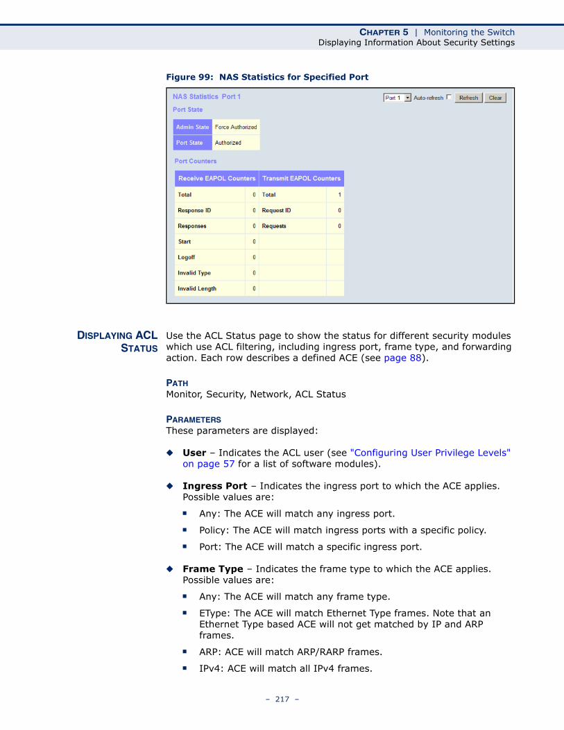
CHAPTER 5 | Monitoring the SwitchDisplaying Information About Security Settings
Figure 99: NAS Statistics for Specified Port
DISPLAYING ACLSTATUS
Use the ACL Status page to show the status for different security modules which use ACL filtering, including ingress port, frame type, and forwarding action. Each row describes a defined ACE (see page 88).
PATH Monitor, Security, Network, ACL Status
PARAMETERSThese parameters are displayed:
◆ User – Indicates the ACL user (see "Configuring User Privilege Levels" on page 57 for a list of software modules).
◆ Ingress Port – Indicates the ingress port to which the ACE applies. Possible values are:
■ Any: The ACE will match any ingress port.
■ Policy: The ACE will match ingress ports with a specific policy.
■ Port: The ACE will match a specific ingress port.
◆ Frame Type – Indicates the frame type to which the ACE applies. Possible values are:
■ Any: The ACE will match any frame type.
■ EType: The ACE will match Ethernet Type frames. Note that an Ethernet Type based ACE will not get matched by IP and ARP frames.
■ ARP: ACE will match ARP/RARP frames.
■ IPv4: ACE will match all IPv4 frames.
– 217 –
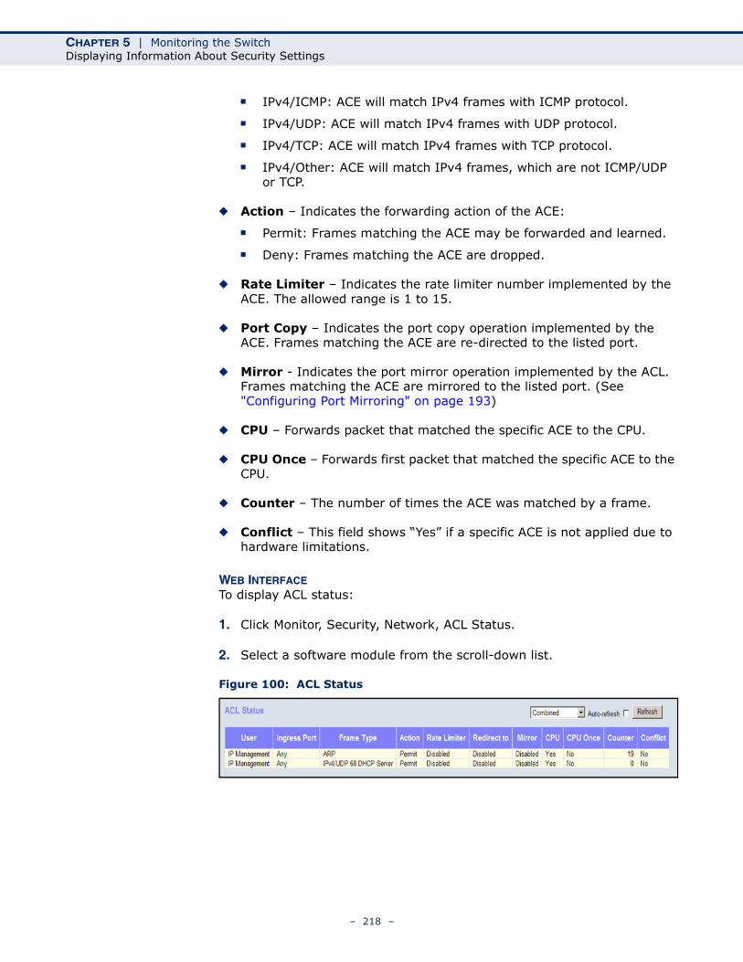
CHAPTER 5 | Monitoring the SwitchDisplaying Information About Security Settings
■ IPv4/ICMP: ACE will match IPv4 frames with ICMP protocol.
■ IPv4/UDP: ACE will match IPv4 frames with UDP protocol.
■ IPv4/TCP: ACE will match IPv4 frames with TCP protocol.
■ IPv4/Other: ACE will match IPv4 frames, which are not ICMP/UDP or TCP.
◆ Action – Indicates the forwarding action of the ACE:
■ Permit: Frames matching the ACE may be forwarded and learned.
■ Deny: Frames matching the ACE are dropped.
◆ Rate Limiter – Indicates the rate limiter number implemented by the ACE. The allowed range is 1 to 15.
◆ Port Copy – Indicates the port copy operation implemented by the ACE. Frames matching the ACE are re-directed to the listed port.
◆ Mirror - Indicates the port mirror operation implemented by the ACL. Frames matching the ACE are mirrored to the listed port. (See "Configuring Port Mirroring" on page 193)
◆ CPU – Forwards packet that matched the specific ACE to the CPU.
◆ CPU Once – Forwards first packet that matched the specific ACE to the CPU.
◆ Counter – The number of times the ACE was matched by a frame.
◆ Conflict – This field shows “Yes” if a specific ACE is not applied due to hardware limitations.
WEB INTERFACETo display ACL status:
1. Click Monitor, Security, Network, ACL Status.
2. Select a software module from the scroll-down list.
Figure 100: ACL Status
– 218 –
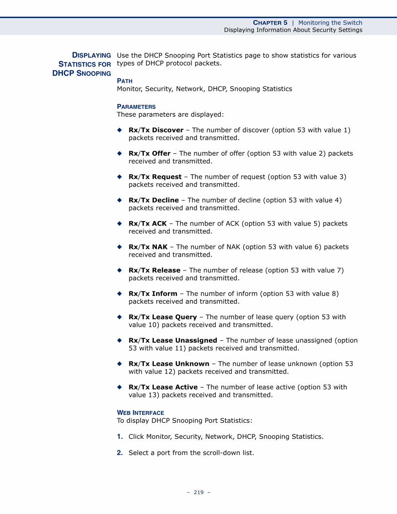
CHAPTER 5 | Monitoring the SwitchDisplaying Information About Security Settings
DISPLAYINGSTATISTICS FOR
DHCP SNOOPING
Use the DHCP Snooping Port Statistics page to show statistics for various types of DHCP protocol packets.
PATH Monitor, Security, Network, DHCP, Snooping Statistics
PARAMETERSThese parameters are displayed:
◆ Rx/Tx Discover – The number of discover (option 53 with value 1) packets received and transmitted.
◆ Rx/Tx Offer – The number of offer (option 53 with value 2) packets received and transmitted.
◆ Rx/Tx Request – The number of request (option 53 with value 3) packets received and transmitted.
◆ Rx/Tx Decline – The number of decline (option 53 with value 4) packets received and transmitted.
◆ Rx/Tx ACK – The number of ACK (option 53 with value 5) packets received and transmitted.
◆ Rx/Tx NAK – The number of NAK (option 53 with value 6) packets received and transmitted.
◆ Rx/Tx Release – The number of release (option 53 with value 7) packets received and transmitted.
◆ Rx/Tx Inform – The number of inform (option 53 with value 8) packets received and transmitted.
◆ Rx/Tx Lease Query – The number of lease query (option 53 with value 10) packets received and transmitted.
◆ Rx/Tx Lease Unassigned – The number of lease unassigned (option 53 with value 11) packets received and transmitted.
◆ Rx/Tx Lease Unknown – The number of lease unknown (option 53 with value 12) packets received and transmitted.
◆ Rx/Tx Lease Active – The number of lease active (option 53 with value 13) packets received and transmitted.
WEB INTERFACETo display DHCP Snooping Port Statistics:
1. Click Monitor, Security, Network, DHCP, Snooping Statistics.
2. Select a port from the scroll-down list.
– 219 –
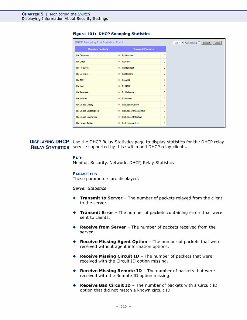
CHAPTER 5 | Monitoring the SwitchDisplaying Information About Security Settings
Figure 101: DHCP Snooping Statistics
DISPLAYING DHCPRELAY STATISTICS
Use the DHCP Relay Statistics page to display statistics for the DHCP relay service supported by this switch and DHCP relay clients.
PATH Monitor, Security, Network, DHCP, Relay Statistics
PARAMETERSThese parameters are displayed:
Server Statistics
◆ Transmit to Server – The number of packets relayed from the client to the server.
◆ Transmit Error – The number of packets containing errors that were sent to clients.
◆ Receive from Server – The number of packets received from the server.
◆ Receive Missing Agent Option – The number of packets that were received without agent information options.
◆ Receive Missing Circuit ID – The number of packets that were received with the Circuit ID option missing.
◆ Receive Missing Remote ID – The number of packets that were received with the Remote ID option missing.
◆ Receive Bad Circuit ID – The number of packets with a Circuit ID option that did not match a known circuit ID.
– 220 –
CHAPTER 5 | Monitoring the SwitchDisplaying Information About Security Settings
◆ Receive Bad Remote ID – The number of packets with a Remote ID option that did not match a known remote ID.
Client Statistics
◆ Transmit to Client – The number of packets that were relayed from the server to a client.
◆ Transmit Error – The number of packets containing errors that were sent to servers.
◆ Receive from Client – The number of packets received from clients.
◆ Receive Agent Option – The number of packets received where the switch.
◆ Replace Agent Option – The number of packets received where the DHCP client packet information was replaced with the switch's relay information.
◆ Keep Agent Option – The number of packets received where the DHCP client packet information was retained.
◆ Drop Agent Option – The number of packets that were dropped because they already contained relay information.
WEB INTERFACETo display DHCP relay statistics, click Monitor, DHCP, Relay Statistics.
Figure 102: DHCP Relay Statistics
DISPLAYING MACADDRESS BINDINGSFOR ARP PACKETS
Open the Dynamic ARP Inspection Table to display address entries sorted first by port, then VLAN ID, MAC address, and finally IP address.
Each page shows up to 999 entries from the Dynamic ARP Inspection table, default being 20, selected through the “entries per page” input field. When first visited, the web page will show the first 20 entries from the beginning of the Dynamic ARP Inspection Table.
PATH Monitor, Security, Network, ARP Inspection
– 221 –
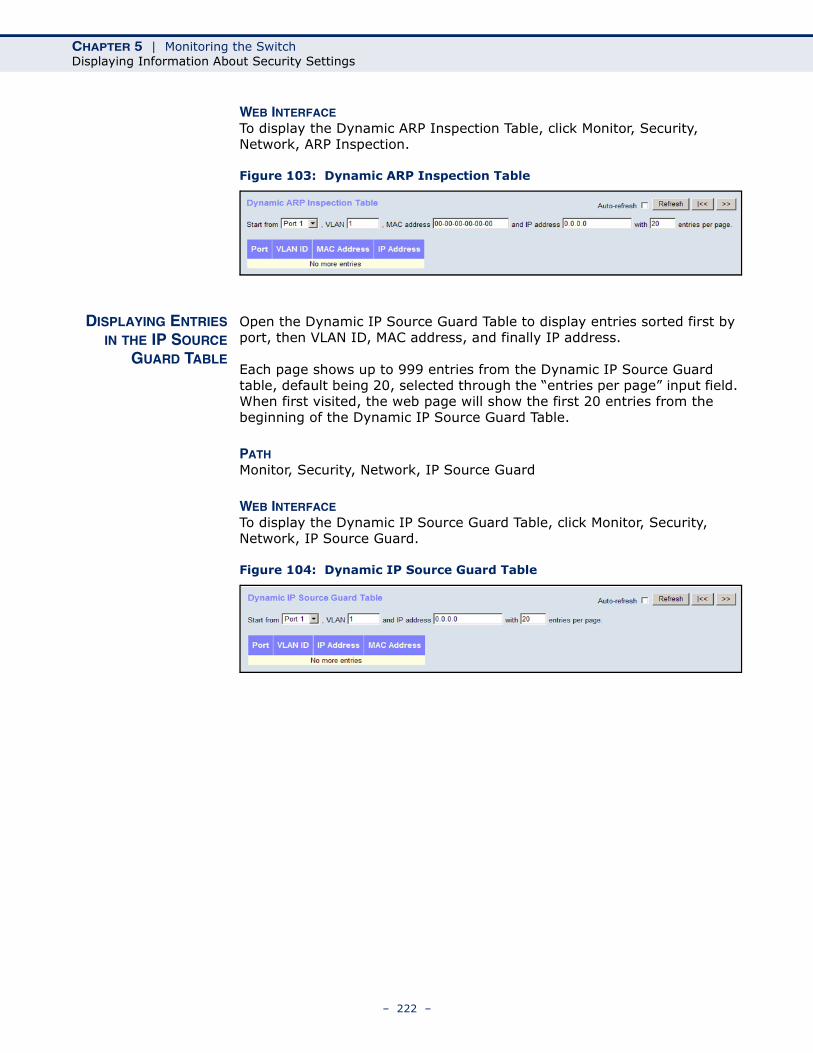
CHAPTER 5 | Monitoring the SwitchDisplaying Information About Security Settings
WEB INTERFACETo display the Dynamic ARP Inspection Table, click Monitor, Security, Network, ARP Inspection.
Figure 103: Dynamic ARP Inspection Table
DISPLAYING ENTRIESIN THE IP SOURCE
GUARD TABLE
Open the Dynamic IP Source Guard Table to display entries sorted first by port, then VLAN ID, MAC address, and finally IP address.
Each page shows up to 999 entries from the Dynamic IP Source Guard table, default being 20, selected through the “entries per page” input field. When first visited, the web page will show the first 20 entries from the beginning of the Dynamic IP Source Guard Table.
PATH Monitor, Security, Network, IP Source Guard
WEB INTERFACETo display the Dynamic IP Source Guard Table, click Monitor, Security, Network, IP Source Guard.
Figure 104: Dynamic IP Source Guard Table
– 222 –
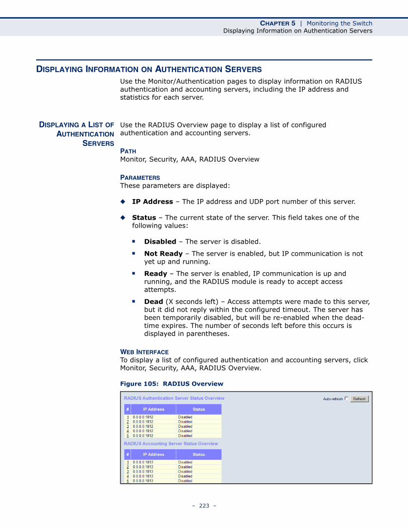
CHAPTER 5 | Monitoring the SwitchDisplaying Information on Authentication Servers
DISPLAYING INFORMATION ON AUTHENTICATION SERVERS Use the Monitor/Authentication pages to display information on RADIUS authentication and accounting servers, including the IP address and statistics for each server.
DISPLAYING A LIST OFAUTHENTICATION
SERVERS
Use the RADIUS Overview page to display a list of configured authentication and accounting servers.
PATH Monitor, Security, AAA, RADIUS Overview
PARAMETERSThese parameters are displayed:
◆ IP Address – The IP address and UDP port number of this server.
◆ Status – The current state of the server. This field takes one of the following values:
■ Disabled – The server is disabled.
■ Not Ready – The server is enabled, but IP communication is not yet up and running.
■ Ready – The server is enabled, IP communication is up and running, and the RADIUS module is ready to accept access attempts.
■ Dead (X seconds left) – Access attempts were made to this server, but it did not reply within the configured timeout. The server has been temporarily disabled, but will be re-enabled when the dead-time expires. The number of seconds left before this occurs is displayed in parentheses.
WEB INTERFACETo display a list of configured authentication and accounting servers, click Monitor, Security, AAA, RADIUS Overview.
Figure 105: RADIUS Overview
– 223 –
CHAPTER 5 | Monitoring the SwitchDisplaying Information on Authentication Servers
DISPLAYINGSTATISTICS FOR
CONFIGUREDAUTHENTICATION
SERVERS
Use the RADIUS Details page to display statistics for configured authentication and accounting servers. The statistics map closely to those specified in RFC4668 - RADIUS Authentication Client MIB.
PATH Monitor, Security, AAA, RADIUS Details
PARAMETERSThese parameters are displayed:
RADIUS Authentication Statistics
◆ Receive Packets
■ Access Accepts – The number of RADIUS Access-Accept packets (valid or invalid) received from this server.
■ Access Rejects – The number of RADIUS Access-Reject packets (valid or invalid) received from this server.
■ Access Challenges – The number of RADIUS Access-Challenge packets (valid or invalid) received from this server.
■ Malformed Access Responses – The number of malformed RADIUS Access-Response packets received from this server. Malformed packets include packets with an invalid length. Bad authenticators or Message Authenticator attributes or unknown types are not included as malformed access responses.
■ Bad Authenticators – The number of RADIUS Access-Response packets containing invalid authenticators or Message Authenticator attributes received from this server.
■ Unknown Types – The number of RADIUS packets of unknown type that were received from this server on the authentication port.
■ Packets Dropped – The number of RADIUS packets that were received from this server on the authentication port and dropped for some other reason.
◆ Transmit Packets
■ Access Requests – The number of RADIUS Access-Request packets sent to this server. This does not include retransmissions.
■ Access Retransmissions – The number of RADIUS Access-Request packets retransmitted to this RADIUS authentication server.
■ Pending Requests – The number of RADIUS Access-Request packets destined for the server that have not yet timed out or received a response. This variable is incremented when an Access-Request is sent and decremented due to receipt of an Access-
– 224 –
CHAPTER 5 | Monitoring the SwitchDisplaying Information on Authentication Servers
Accept, Access-Reject, Access-Challenge, timeout, or retransmission.
■ Timeouts – The number of authentication timeouts to the server. After a timeout, the client may retry to the same server, send to a different server, or give up. A retry to the same server is counted as a retransmit as well as a timeout. A send to a different server is counted as a Request as well as a timeout.
◆ Other Info
■ State – The current state of the server. This field takes one of the following values:
■ Disabled – The server is disabled.
■ Not Ready – The server is enabled, but IP communication is not yet up and running.
■ Ready – The server is enabled, IP communication is up and running, and the RADIUS module is ready to accept access attempts.
■ Dead (X seconds left) – Access attempts were made to this server, but it did not reply within the configured timeout. The server has been temporarily disabled, but will be re-enabled when the dead-time expires. The number of seconds left before this occurs is displayed in parentheses.
■ Round-Trip Time – The time interval (measured in milliseconds) between the most recent Access-Reply/Access-Challenge and the Access-Request that matched it from the RADIUS authentication server. The granularity of this measurement is 100 ms. A value of 0 ms indicates that there hasn't been round-trip communication with the server yet.
RADIUS Accounting Statistics
◆ Receive Packets
■ Responses – The number of RADIUS packets (valid or invalid) received from the server.
■ Malformed Responses – The number of malformed RADIUS packets received from the server. Malformed packets include packets with an invalid length. Bad authenticators or unknown types are not included as malformed access responses.
■ Bad Authenticators – The number of RADIUS packets containing invalid authenticators received from the server.
■ Unknown Types – The number of RADIUS packets of unknown types that were received from the server on the accounting port.
– 225 –
CHAPTER 5 | Monitoring the SwitchDisplaying Information on Authentication Servers
■ Packets Dropped – The number of RADIUS packets that were received from the server on the accounting port and dropped for some other reason.
◆ Transmit Packets
■ Requests – The number of RADIUS packets sent to the server. This does not include retransmissions.
■ Retransmissions – The number of RADIUS packets retransmitted to the RADIUS accounting server.
■ Pending Requests – The number of RADIUS packets destined for the server that have not yet timed out or received a response. This variable is incremented when a Request is sent and decremented due to receipt of a Response, timeout, or retransmission.
■ Timeouts – The number of accounting timeouts to the server. After a timeout, the client may retry to the same server, send to a different server, or give up. A retry to the same server is counted as a retransmit as well as a timeout. A send to a different server is counted as a Request as well as a timeout.
◆ Other Info
■ State – The current state of the server. It takes one of the following values:
■ Disabled – The server is disabled.
■ Not Ready – The server is enabled, but IP communication is not yet up and running.
■ Ready – The server is enabled, IP communication is up and running, and the RADIUS module is ready to accept accounting attempts.
■ Dead (X seconds left) – Accounting attempts were made to this server, but it did not reply within the configured timeout. The server has temporarily been disabled, but will get re-enabled when the dead-time expires. The number of seconds left before this occurs is displayed in parentheses. This state is only reachable when more than one server is enabled.
■ Round-Trip Time – The time interval (measured in milliseconds) between the most recent Response and the Request that matched it from the RADIUS accounting server. The granularity of this measurement is 100 ms. A value of 0 ms indicates that there hasn't been round-trip communication with the server yet.
– 226 –
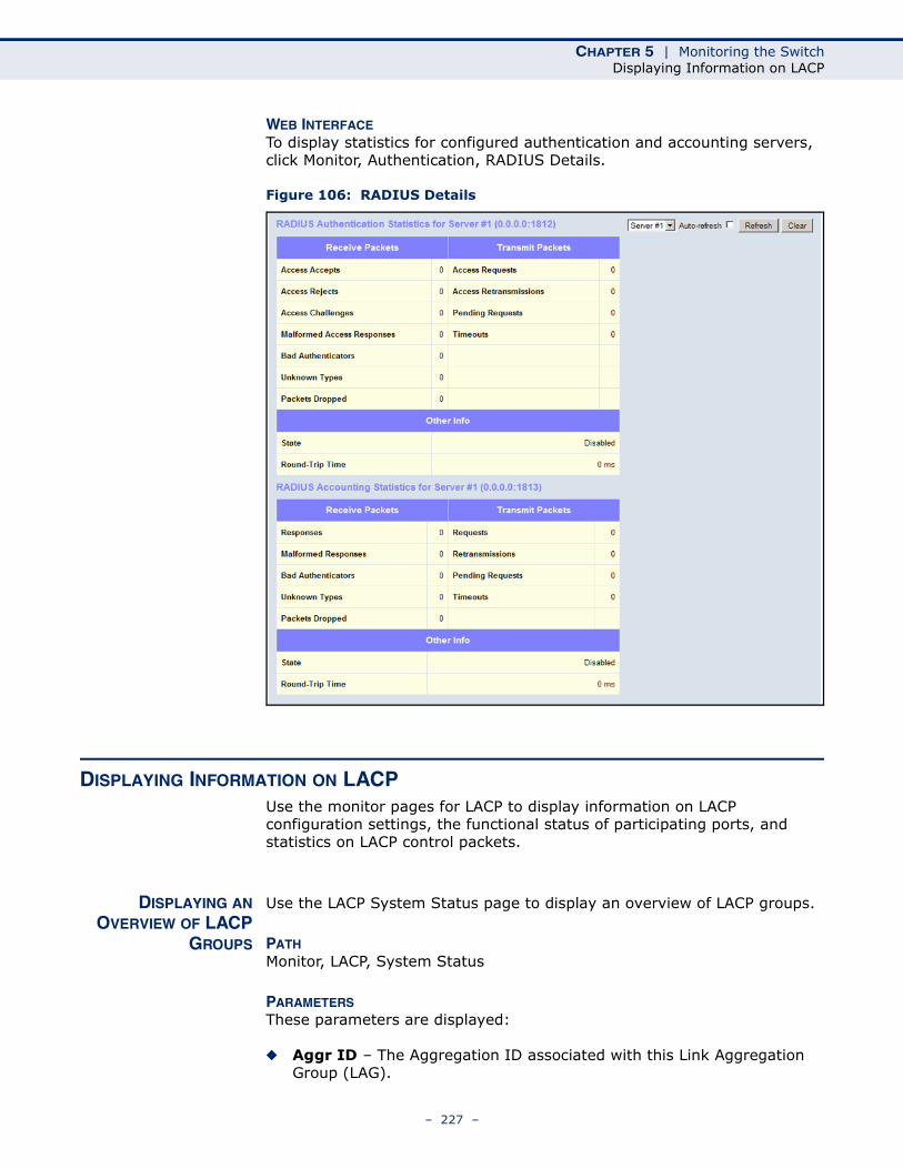
CHAPTER 5 | Monitoring the SwitchDisplaying Information on LACP
WEB INTERFACETo display statistics for configured authentication and accounting servers, click Monitor, Authentication, RADIUS Details.
Figure 106: RADIUS Details
DISPLAYING INFORMATION ON LACP Use the monitor pages for LACP to display information on LACP configuration settings, the functional status of participating ports, and statistics on LACP control packets.
DISPLAYING ANOVERVIEW OF LACP
GROUPS
Use the LACP System Status page to display an overview of LACP groups.
PATH Monitor, LACP, System Status
PARAMETERSThese parameters are displayed:
◆ Aggr ID – The Aggregation ID associated with this Link Aggregation Group (LAG).
– 227 –
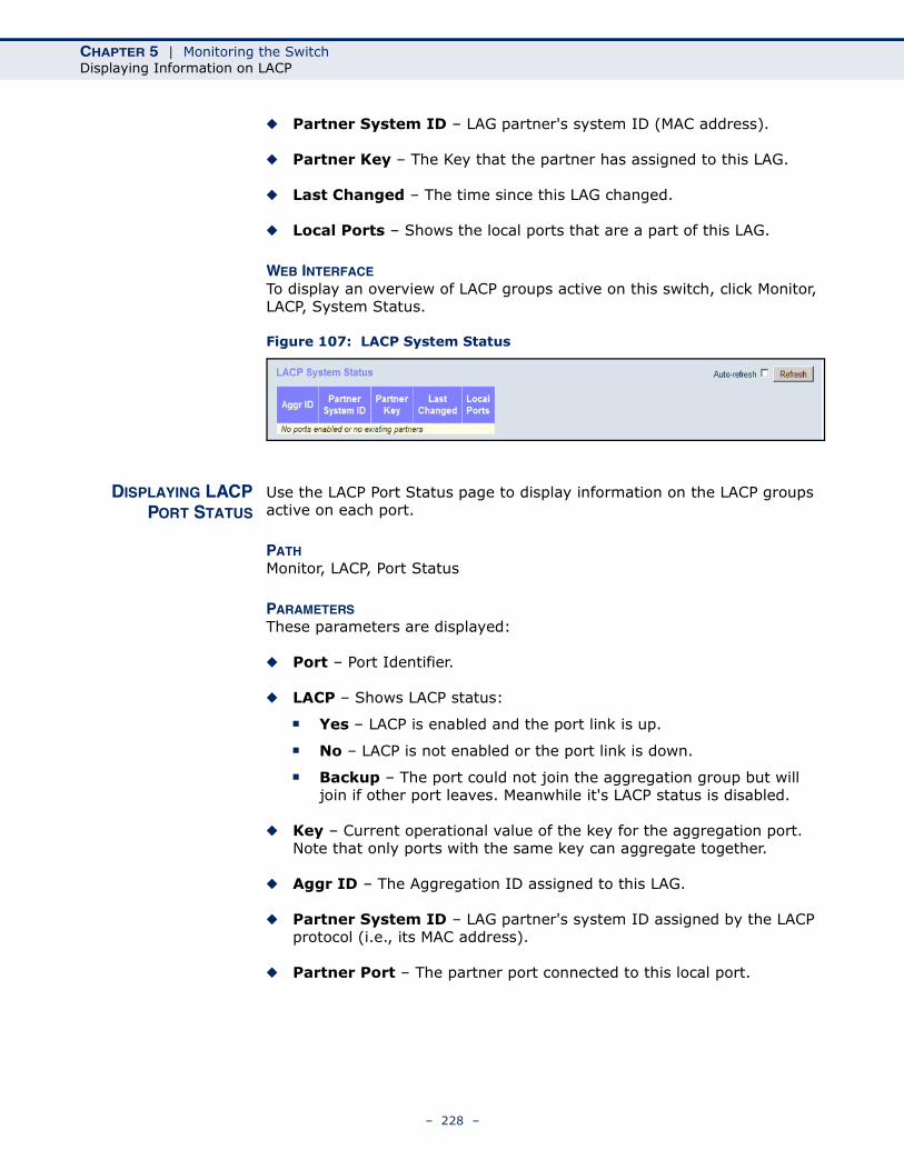
CHAPTER 5 | Monitoring the SwitchDisplaying Information on LACP
◆ Partner System ID – LAG partner's system ID (MAC address).
◆ Partner Key – The Key that the partner has assigned to this LAG.
◆ Last Changed – The time since this LAG changed.
◆ Local Ports – Shows the local ports that are a part of this LAG.
WEB INTERFACETo display an overview of LACP groups active on this switch, click Monitor, LACP, System Status.
Figure 107: LACP System Status
DISPLAYING LACPPORT STATUS
Use the LACP Port Status page to display information on the LACP groups active on each port.
PATH Monitor, LACP, Port Status
PARAMETERSThese parameters are displayed:
◆ Port – Port Identifier.
◆ LACP – Shows LACP status:
■ Yes – LACP is enabled and the port link is up.
■ No – LACP is not enabled or the port link is down.
■ Backup – The port could not join the aggregation group but will join if other port leaves. Meanwhile it's LACP status is disabled.
◆ Key – Current operational value of the key for the aggregation port. Note that only ports with the same key can aggregate together.
◆ Aggr ID – The Aggregation ID assigned to this LAG.
◆ Partner System ID – LAG partner's system ID assigned by the LACP protocol (i.e., its MAC address).
◆ Partner Port – The partner port connected to this local port.
– 228 –

CHAPTER 5 | Monitoring the SwitchDisplaying Information on LACP
WEB INTERFACETo display LACP status for local ports this switch, click Monitor, LACP, Port Status.
Figure 108: LACP Port Status
DISPLAYING LACPPORT STATISTICS
Use the LACP Port Statistics page to display statistics on LACP control packets crossing on each port.
PATH Monitor, LACP, Port Statistics
PARAMETERSThese parameters are displayed:
◆ Port – Port Identifier.
◆ LACP Transmitted – The number of LACP frames sent from each port.
◆ LACP Received – The number of LACP frames received at each port.
◆ Discarded – The number of unknown or illegal LACP frames that have been discarded at each port.
WEB INTERFACETo display LACP statistics for local ports this switch, click Monitor, LACP, Port Statistics.
Figure 109: LACP Port Statistics
– 229 –
CHAPTER 5 | Monitoring the SwitchDisplaying Information on the Spanning Tree
DISPLAYING INFORMATION ON THE SPANNING TREE Use the monitor pages for Spanning Tree to display information on spanning tree bridge status, the functional status of participating ports, and statistics on spanning tree protocol packets.
DISPLAYING BRIDGESTATUS FOR STA
Use the Bridge Status page to display STA information on the global bridge (i.e., this switch) and individual ports.
PATH Monitor, Spanning Tree, Bridge Status
PARAMETERSThese parameters are displayed:
STA Bridges
◆ MSTI – The Bridge Instance. This is also a link to the STP Detailed Bridge Status.
◆ Bridge ID – A unique identifier for this bridge, consisting of the bridge priority, and MAC address (where the address is taken from the switch system).
◆ Root ID – The priority and MAC address of the device in the Spanning Tree that this switch has been accepted as the root device.
◆ Root Port – The number of the port on this switch that is closest to the root. This switch communicates with the root device through this port. If there is no root port, then this switch has been accepted as the root device of the Spanning Tree network.
◆ Root Cost – The path cost from the root port on this switch to the root device. For the root bridge this is zero. For all other bridges, it is the sum of the port path costs on the least cost path to the root bridge.
◆ Topology Flag – The current state of the Topology Change Notification flag (TCN) for this bridge instance.
◆ Topology Change Last – Time since the Spanning Tree was last reconfigured.
STP Detailed Bridge Status – Click on a bridge instance under the MSTI field to display detailed information on the selected entry. The following additional information is displayed.
◆ Bridge Instance – The Bridge instance - CIST, MST1, ...
◆ Regional Root – The Bridge ID of the currently elected regional root bridge, inside the MSTP region of this bridge. (This parameter only applies to the CIST instance.)
– 230 –
CHAPTER 5 | Monitoring the SwitchDisplaying Information on the Spanning Tree
◆ Internal Root Cost – The Regional Root Path Cost. For the Regional Root Bridge this is zero. For all other CIST instances in the same MSTP region, it is the sum of the Internal Port Path Costs on the least cost path to the Internal Root Bridge. (This parameter only applies to the CIST instance.)
◆ Topology Change Count – The number of times the Spanning Tree has been reconfigured (during a one-second interval).
CIST Ports & Aggregations State
◆ Port – Port Identifier.
◆ Port ID – The port identifier as used by the RSTP protocol. This consists of the priority part and the logical port index of the bridge port.
◆ Role – Roles are assigned according to whether the port is part of the active topology connecting the bridge to the root bridge (i.e., root port), connecting a LAN through the bridge to the root bridge (i.e., designated port); or is an alternate or backup port that may provide connectivity if other bridges, bridge ports, or LANs fail or are removed.
◆ State – Displays the current state of this port in the Spanning Tree:
■ Blocking – Port receives STA configuration messages, but does not forward packets.
■ Learning – Port has transmitted configuration messages for an interval set by the Forward Delay parameter without receiving contradictory information. Port address table is cleared, and the port begins learning addresses.
■ Forwarding – Port forwards packets, and continues learning addresses.
◆ Path Cost – The contribution of this port to the path cost of paths towards the spanning tree root which include this port. This will either be a value computed from the Auto setting, or any explicitly configured value.
◆ Edge – The current RSTP port (operational) Edge Flag. An Edge Port is a switch port to which no bridges are attached. The flag may be automatically computed or explicitly configured. Each Edge Port transitions directly to the Forwarding Port State, since there is no possibility of it participating in a loop.
◆ Point2Point – Indicates a connection to exactly one other bridge. The flag may be automatically computed or explicitly configured. The point-to-point properties of a port affect how fast it can transition RSTP states.
◆ Uptime – The time since the bridge port was last initialized.
– 231 –
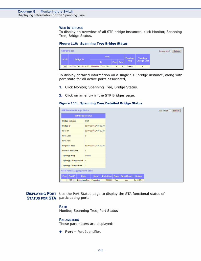
CHAPTER 5 | Monitoring the SwitchDisplaying Information on the Spanning Tree
WEB INTERFACETo display an overview of all STP bridge instances, click Monitor, Spanning Tree, Bridge Status.
Figure 110: Spanning Tree Bridge Status
To display detailed information on a single STP bridge instance, along with port state for all active ports associated,
1. Click Monitor, Spanning Tree, Bridge Status.
2. Click on an entry in the STP Bridges page.
Figure 111: Spanning Tree Detailed Bridge Status
DISPLAYING PORTSTATUS FOR STA
Use the Port Status page to display the STA functional status of participating ports.
PATH Monitor, Spanning Tree, Port Status
PARAMETERSThese parameters are displayed:
◆ Port – Port Identifier.
– 232 –
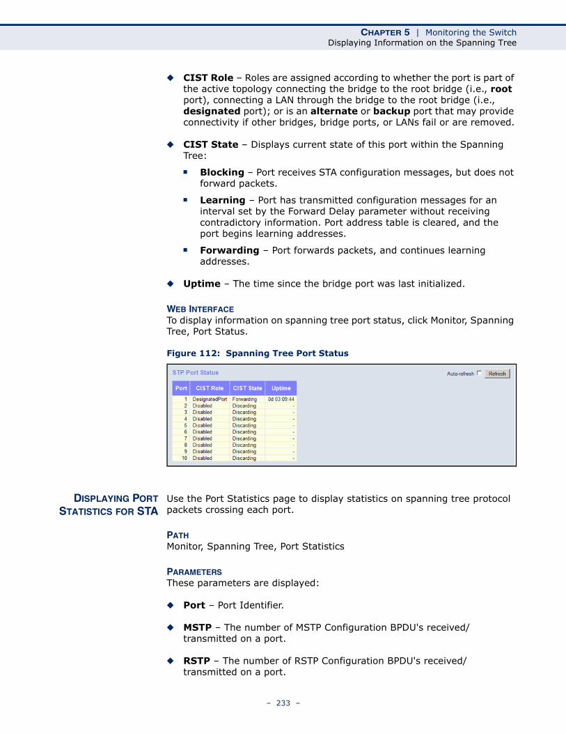
CHAPTER 5 | Monitoring the SwitchDisplaying Information on the Spanning Tree
◆ CIST Role – Roles are assigned according to whether the port is part of the active topology connecting the bridge to the root bridge (i.e., root port), connecting a LAN through the bridge to the root bridge (i.e., designated port); or is an alternate or backup port that may provide connectivity if other bridges, bridge ports, or LANs fail or are removed.
◆ CIST State – Displays current state of this port within the Spanning Tree:
■ Blocking – Port receives STA configuration messages, but does not forward packets.
■ Learning – Port has transmitted configuration messages for an interval set by the Forward Delay parameter without receiving contradictory information. Port address table is cleared, and the port begins learning addresses.
■ Forwarding – Port forwards packets, and continues learning addresses.
◆ Uptime – The time since the bridge port was last initialized.
WEB INTERFACETo display information on spanning tree port status, click Monitor, Spanning Tree, Port Status.
Figure 112: Spanning Tree Port Status
DISPLAYING PORTSTATISTICS FOR STA
Use the Port Statistics page to display statistics on spanning tree protocol packets crossing each port.
PATH Monitor, Spanning Tree, Port Statistics
PARAMETERSThese parameters are displayed:
◆ Port – Port Identifier.
◆ MSTP – The number of MSTP Configuration BPDU's received/transmitted on a port.
◆ RSTP – The number of RSTP Configuration BPDU's received/transmitted on a port.
– 233 –
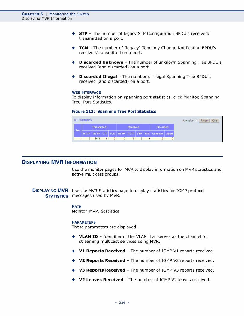
CHAPTER 5 | Monitoring the SwitchDisplaying MVR Information
◆ STP – The number of legacy STP Configuration BPDU's received/transmitted on a port.
◆ TCN – The number of (legacy) Topology Change Notification BPDU's received/transmitted on a port.
◆ Discarded Unknown – The number of unknown Spanning Tree BPDU's received (and discarded) on a port.
◆ Discarded Illegal – The number of illegal Spanning Tree BPDU's received (and discarded) on a port.
WEB INTERFACETo display information on spanning port statistics, click Monitor, Spanning Tree, Port Statistics.
Figure 113: Spanning Tree Port Statistics
DISPLAYING MVR INFORMATION
Use the monitor pages for MVR to display information on MVR statistics and active multicast groups.
DISPLAYING MVRSTATISTICS
Use the MVR Statistics page to display statistics for IGMP protocol messages used by MVR.
PATH Monitor, MVR, Statistics
PARAMETERSThese parameters are displayed:
◆ VLAN ID – Identifier of the VLAN that serves as the channel for streaming multicast services using MVR.
◆ V1 Reports Received – The number of IGMP V1 reports received.
◆ V2 Reports Received – The number of IGMP V2 reports received.
◆ V3 Reports Received – The number of IGMP V3 reports received.
◆ V2 Leaves Received – The number of IGMP V2 leaves received.
– 234 –
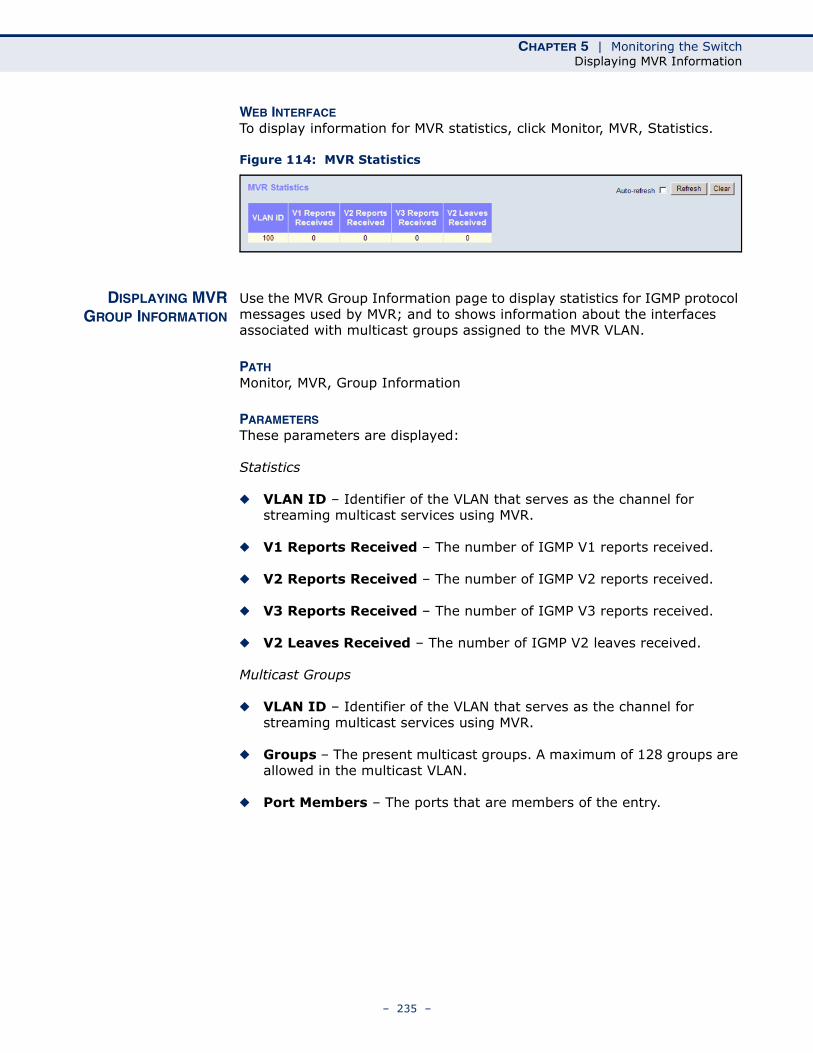
CHAPTER 5 | Monitoring the SwitchDisplaying MVR Information
WEB INTERFACETo display information for MVR statistics, click Monitor, MVR, Statistics.
Figure 114: MVR Statistics
DISPLAYING MVRGROUP INFORMATION
Use the MVR Group Information page to display statistics for IGMP protocol messages used by MVR; and to shows information about the interfaces associated with multicast groups assigned to the MVR VLAN.
PATH Monitor, MVR, Group Information
PARAMETERSThese parameters are displayed:
Statistics
◆ VLAN ID – Identifier of the VLAN that serves as the channel for streaming multicast services using MVR.
◆ V1 Reports Received – The number of IGMP V1 reports received.
◆ V2 Reports Received – The number of IGMP V2 reports received.
◆ V3 Reports Received – The number of IGMP V3 reports received.
◆ V2 Leaves Received – The number of IGMP V2 leaves received.
Multicast Groups
◆ VLAN ID – Identifier of the VLAN that serves as the channel for streaming multicast services using MVR.
◆ Groups – The present multicast groups. A maximum of 128 groups are allowed in the multicast VLAN.
◆ Port Members – The ports that are members of the entry.
– 235 –

CHAPTER 5 | Monitoring the SwitchShowing IGMP Snooping Information
WEB INTERFACETo display information for MVR statistics and multicast groups, click Monitor, MVR, Group Information.
Figure 115: MVR Group Information
SHOWING IGMP SNOOPING INFORMATION
Use the IGMP Snooping pages to display IGMP snooping statistics, port members of each service group, and information on source-specific groups.
SHOWING IGMPSNOOPING STATUS
Use the IGMP Snooping Status page to display IGMP querier status, snooping statistics for each VLAN carrying IGMP traffic, and the ports connected to an upstream multicast router/switch.
PATH Monitor, IPMC, IGMP Snooping, Status
PARAMETERSThese parameters are displayed:
Statistics
◆ VLAN ID – VLAN Identifier.
◆ Querier Version – IGMP version used by the switch when serving as the IGMP querier.
◆ Host Version – IGMP version used when used by this switch when serving as a host in IGMP proxy mode.
◆ Querier Status – Shows the Querier status as “ACTIVE” or “IDLE.” When enabled, the switch can serve as the Querier, which is responsible for asking hosts if they want to receive multicast traffic.
◆ Querier Transmitted – The number of transmitted Querier messages.
◆ Querier Received – The number of received Querier messages.
◆ V1 Reports Received – The number of received IGMP Version 1 reports.
– 236 –
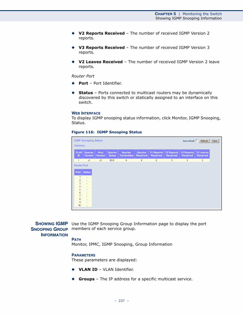
CHAPTER 5 | Monitoring the SwitchShowing IGMP Snooping Information
◆ V2 Reports Received – The number of received IGMP Version 2 reports.
◆ V3 Reports Received – The number of received IGMP Version 3 reports.
◆ V2 Leaves Received – The number of received IGMP Version 2 leave reports.
Router Port
◆ Port – Port Identifier.
◆ Status – Ports connected to multicast routers may be dynamically discovered by this switch or statically assigned to an interface on this switch.
WEB INTERFACETo display IGMP snooping status information, click Monitor, IGMP Snooping, Status.
Figure 116: IGMP Snooping Status
SHOWING IGMPSNOOPING GROUP
INFORMATION
Use the IGMP Snooping Group Information page to display the port members of each service group.
PATH Monitor, IPMC, IGMP Snooping, Group Information
PARAMETERSThese parameters are displayed:
◆ VLAN ID – VLAN Identifier.
◆ Groups – The IP address for a specific multicast service.
– 237 –
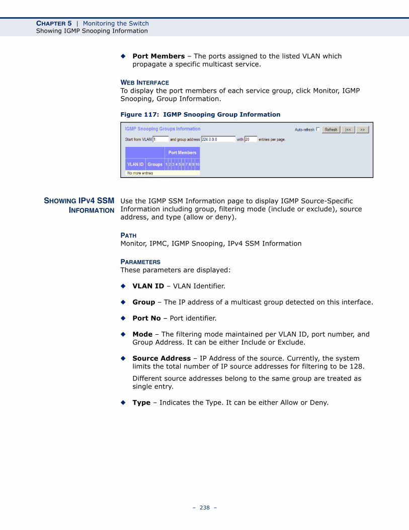
CHAPTER 5 | Monitoring the SwitchShowing IGMP Snooping Information
◆ Port Members – The ports assigned to the listed VLAN which propagate a specific multicast service.
WEB INTERFACETo display the port members of each service group, click Monitor, IGMP Snooping, Group Information.
Figure 117: IGMP Snooping Group Information
SHOWING IPV4 SSMINFORMATION
Use the IGMP SSM Information page to display IGMP Source-Specific Information including group, filtering mode (include or exclude), source address, and type (allow or deny).
PATH Monitor, IPMC, IGMP Snooping, IPv4 SSM Information
PARAMETERSThese parameters are displayed:
◆ VLAN ID – VLAN Identifier.
◆ Group – The IP address of a multicast group detected on this interface.
◆ Port No – Port identifier.
◆ Mode – The filtering mode maintained per VLAN ID, port number, and Group Address. It can be either Include or Exclude.
◆ Source Address – IP Address of the source. Currently, the system limits the total number of IP source addresses for filtering to be 128.
Different source addresses belong to the same group are treated as single entry.
◆ Type – Indicates the Type. It can be either Allow or Deny.
– 238 –
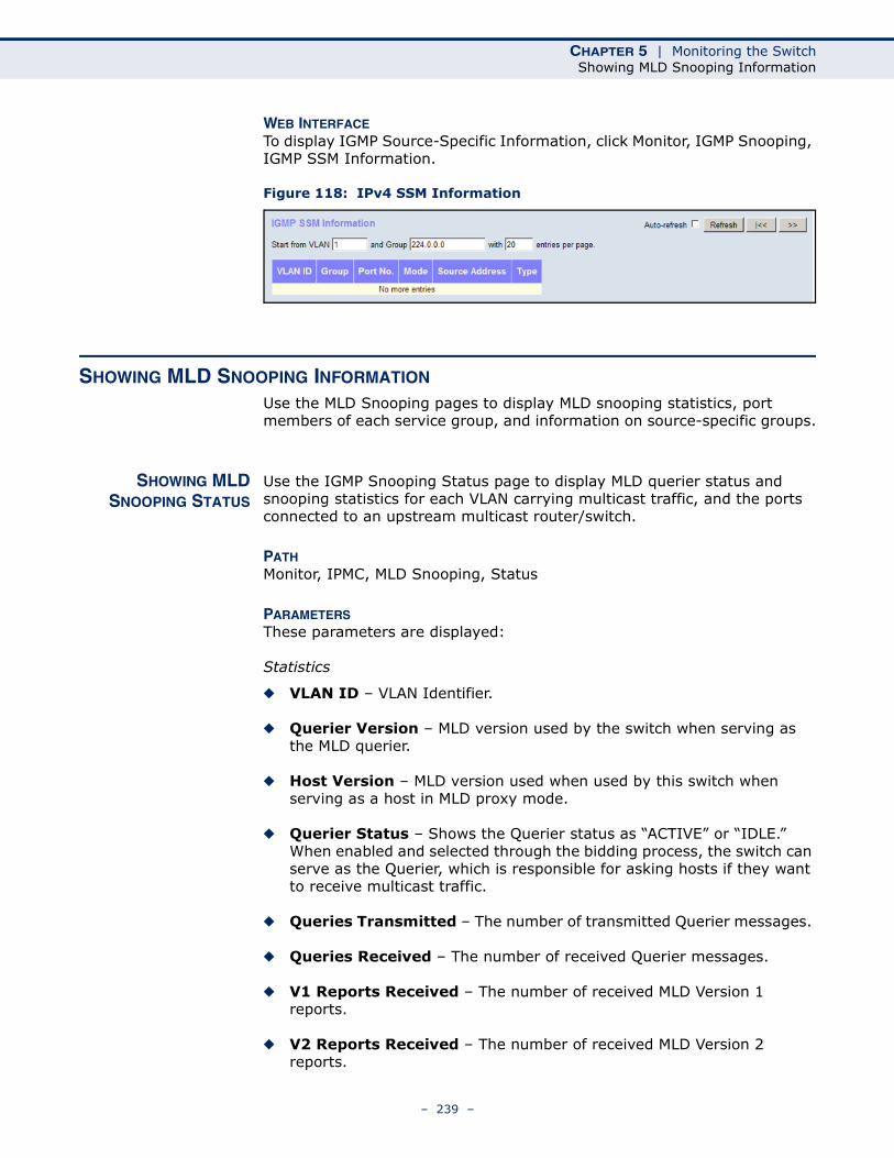
CHAPTER 5 | Monitoring the SwitchShowing MLD Snooping Information
WEB INTERFACETo display IGMP Source-Specific Information, click Monitor, IGMP Snooping, IGMP SSM Information.
Figure 118: IPv4 SSM Information
SHOWING MLD SNOOPING INFORMATION
Use the MLD Snooping pages to display MLD snooping statistics, port members of each service group, and information on source-specific groups.
SHOWING MLDSNOOPING STATUS
Use the IGMP Snooping Status page to display MLD querier status and snooping statistics for each VLAN carrying multicast traffic, and the ports connected to an upstream multicast router/switch.
PATH Monitor, IPMC, MLD Snooping, Status
PARAMETERSThese parameters are displayed:
Statistics
◆ VLAN ID – VLAN Identifier.
◆ Querier Version – MLD version used by the switch when serving as the MLD querier.
◆ Host Version – MLD version used when used by this switch when serving as a host in MLD proxy mode.
◆ Querier Status – Shows the Querier status as “ACTIVE” or “IDLE.” When enabled and selected through the bidding process, the switch can serve as the Querier, which is responsible for asking hosts if they want to receive multicast traffic.
◆ Queries Transmitted – The number of transmitted Querier messages.
◆ Queries Received – The number of received Querier messages.
◆ V1 Reports Received – The number of received MLD Version 1 reports.
◆ V2 Reports Received – The number of received MLD Version 2 reports.
– 239 –
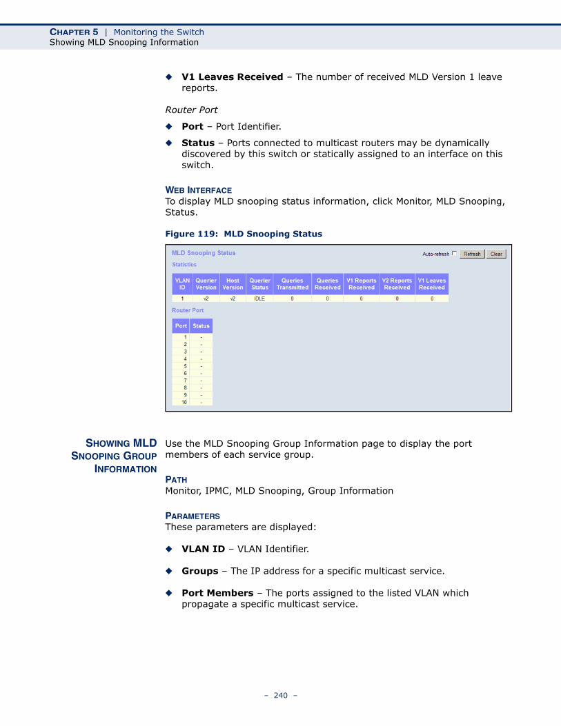
CHAPTER 5 | Monitoring the SwitchShowing MLD Snooping Information
◆ V1 Leaves Received – The number of received MLD Version 1 leave reports.
Router Port
◆ Port – Port Identifier.
◆ Status – Ports connected to multicast routers may be dynamically discovered by this switch or statically assigned to an interface on this switch.
WEB INTERFACETo display MLD snooping status information, click Monitor, MLD Snooping, Status.
Figure 119: MLD Snooping Status
SHOWING MLDSNOOPING GROUP
INFORMATION
Use the MLD Snooping Group Information page to display the port members of each service group.
PATH Monitor, IPMC, MLD Snooping, Group Information
PARAMETERSThese parameters are displayed:
◆ VLAN ID – VLAN Identifier.
◆ Groups – The IP address for a specific multicast service.
◆ Port Members – The ports assigned to the listed VLAN which propagate a specific multicast service.
– 240 –
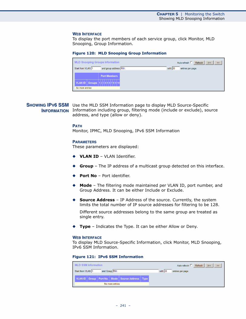
CHAPTER 5 | Monitoring the SwitchShowing MLD Snooping Information
WEB INTERFACETo display the port members of each service group, click Monitor, MLD Snooping, Group Information.
Figure 120: MLD Snooping Group Information
SHOWING IPV6 SSMINFORMATION
Use the MLD SSM Information page to display MLD Source-Specific Information including group, filtering mode (include or exclude), source address, and type (allow or deny).
PATH Monitor, IPMC, MLD Snooping, IPv6 SSM Information
PARAMETERSThese parameters are displayed:
◆ VLAN ID – VLAN Identifier.
◆ Group – The IP address of a multicast group detected on this interface.
◆ Port No – Port identifier.
◆ Mode – The filtering mode maintained per VLAN ID, port number, and Group Address. It can be either Include or Exclude.
◆ Source Address – IP Address of the source. Currently, the system limits the total number of IP source addresses for filtering to be 128.
Different source addresses belong to the same group are treated as single entry.
◆ Type – Indicates the Type. It can be either Allow or Deny.
WEB INTERFACETo display MLD Source-Specific Information, click Monitor, MLD Snooping, IPv6 SSM Information.
Figure 121: IPv6 SSM Information
– 241 –
CHAPTER 5 | Monitoring the SwitchDisplaying LLDP Information
DISPLAYING LLDP INFORMATION
Use the monitor pages for LLDP to display information advertised by LLDP neighbors and statistics on LLDP control frames.
DISPLAYING LLDPNEIGHBOR
INFORMATION
Use the LLDP Neighbor Information page to display information about devices connected directly to the switch’s ports which are advertising information through LLDP.
PATH Monitor, LLDP, Neighbors
PARAMETERSThese parameters are displayed:
◆ Local Port – The local port to which a remote LLDP-capable device is attached.
◆ Chassis ID – An octet string indicating the specific identifier for the particular chassis in this system.
◆ Remote Port ID – A string that contains the specific identifier for the port from which this LLDPDU was transmitted.
◆ System Name – A string that indicates the system’s assigned name.
◆ Port Description – A string that indicates the port’s description. If RFC 2863 is implemented, the ifDescr object should be used for this field.
◆ System Capabilities – The capabilities that define the primary function(s) of the system as shown in the following table:
When a capability is enabled, the capability is followed by (+). If the capability is disabled, the capability is followed by (-).
Table 13: System Capabilities
ID Basis Reference
Other –
Repeater IETF RFC 2108
Bridge IETF RFC 2674
WLAN Access Point IEEE 802.11 MIB
Router IETF RFC 1812
Telephone IETF RFC 2011
DOCSIS cable device
IETF RFC 2669 and IETF RFC 2670
Station only IETF RFC 2011
– 242 –
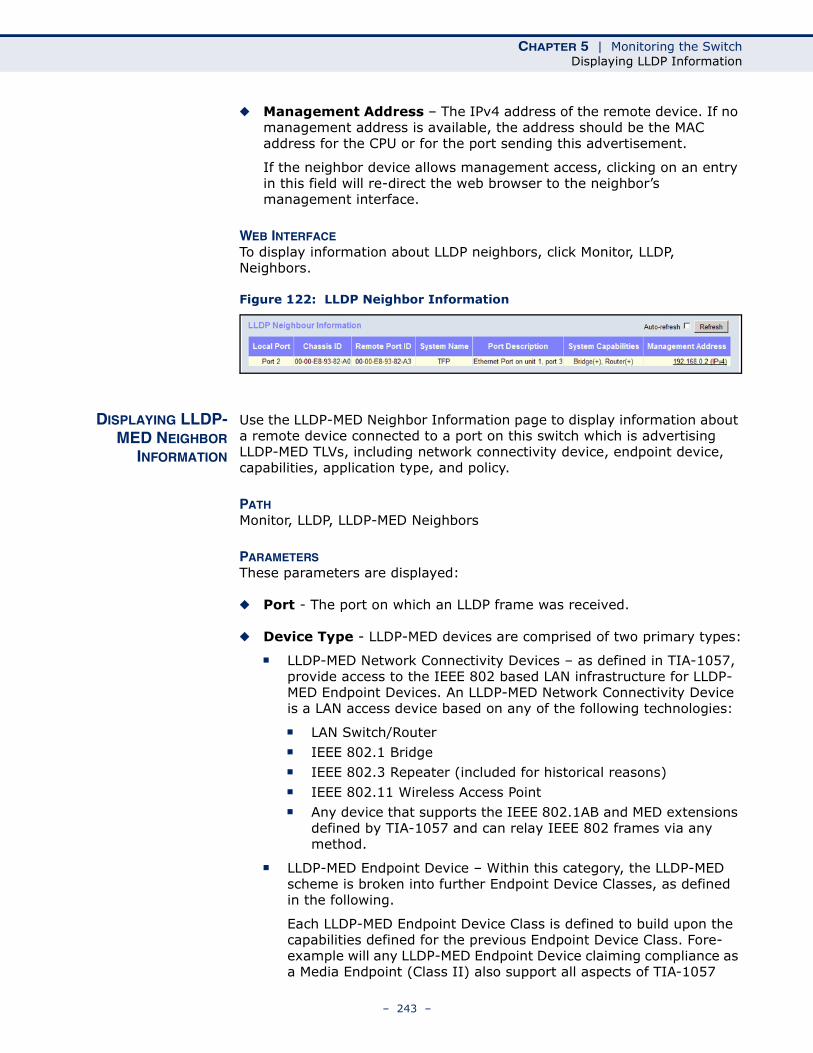
CHAPTER 5 | Monitoring the SwitchDisplaying LLDP Information
◆ Management Address – The IPv4 address of the remote device. If no management address is available, the address should be the MAC address for the CPU or for the port sending this advertisement.
If the neighbor device allows management access, clicking on an entry in this field will re-direct the web browser to the neighbor’s management interface.
WEB INTERFACETo display information about LLDP neighbors, click Monitor, LLDP, Neighbors.
Figure 122: LLDP Neighbor Information
DISPLAYING LLDP-MED NEIGHBOR
INFORMATION
Use the LLDP-MED Neighbor Information page to display information about a remote device connected to a port on this switch which is advertising LLDP-MED TLVs, including network connectivity device, endpoint device, capabilities, application type, and policy.
PATH Monitor, LLDP, LLDP-MED Neighbors
PARAMETERSThese parameters are displayed:
◆ Port - The port on which an LLDP frame was received.
◆ Device Type - LLDP-MED devices are comprised of two primary types:
■ LLDP-MED Network Connectivity Devices – as defined in TIA-1057, provide access to the IEEE 802 based LAN infrastructure for LLDP-MED Endpoint Devices. An LLDP-MED Network Connectivity Device is a LAN access device based on any of the following technologies:
■ LAN Switch/Router■ IEEE 802.1 Bridge■ IEEE 802.3 Repeater (included for historical reasons)■ IEEE 802.11 Wireless Access Point■ Any device that supports the IEEE 802.1AB and MED extensions
defined by TIA-1057 and can relay IEEE 802 frames via any method.
■ LLDP-MED Endpoint Device – Within this category, the LLDP-MED scheme is broken into further Endpoint Device Classes, as defined in the following.
Each LLDP-MED Endpoint Device Class is defined to build upon the capabilities defined for the previous Endpoint Device Class. Fore-example will any LLDP-MED Endpoint Device claiming compliance as a Media Endpoint (Class II) also support all aspects of TIA-1057
– 243 –
CHAPTER 5 | Monitoring the SwitchDisplaying LLDP Information
applicable to Generic Endpoints (Class I), and any LLDP-MED Endpoint Device claiming compliance as a Communication Device (Class III) will also support all aspects of TIA-1057 applicable to both Media Endpoints (Class II) and Generic Endpoints (Class I).
■ LLDP-MED Generic Endpoint (Class I) – Applicable to all endpoint products that require the base LLDP discovery services defined in TIA-1057, however do not support IP media or act as an end-user communication appliance. Such devices may include (but are not limited to) IP Communication Controllers, other communication related servers, or any device requiring basic services as defined in TIA-1057.
Discovery services defined in this class include LAN configuration, device location, network policy, power management, and inventory management.
■ LLDP-MED Media Endpoint (Class II) – Applicable to all endpoint products that have IP media capabilities however may or may not be associated with a particular end user. Capabilities include all of the capabilities defined for the previous Generic Endpoint Class (Class I), and are extended to include aspects related to media streaming. Example product categories expected to adhere to this class include (but are not limited to) Voice / Media Gateways, Conference Bridges, Media Servers, and similar.
Discovery services defined in this class include media-type-specific network layer policy discovery.
■ LLDP-MED Communication Endpoint (Class III) – Applicable to all endpoint products that act as end user communication appliances supporting IP media. Capabilities include all of the capabilities defined for the previous Generic Endpoint (Class I) and Media Endpoint (Class II) classes, and are extended to include aspects related to end user devices. Example product categories expected to adhere to this class include (but are not limited to) end user communication appliances, such as IP Phones, PC-based softphones, or other communication appliances that directly support the end user.
Discovery services defined in this class include provision of location identifier (including ECS / E911 information), embedded L2 switch support, inventory management
◆ LLDP-MED Capabilities – The neighbor unit's LLDP-MED capabilities:
■ LLDP-MED capabilities■ Network Policy■ Location Identification■ Extended Power via MDI - PSE■ Extended Power vis MDI - PD■ Inventory■ Reserved
– 244 –
CHAPTER 5 | Monitoring the SwitchDisplaying LLDP Information
◆ Application Type – The primary function of the application(s) defined for this network policy, and advertised by an Endpoint or Network Connectivity Device. The possible application types are described under "Configuring LLDP-MED TLVs" on page 148.
◆ Policy – This field displays one of the following values:
■ Unknown: The network policy for the specified application type is currently unknown.
■ Defined: The network policy is defined.
◆ Tag – Indicates whether the specified application type is using a tagged or an untagged VLAN.
◆ VLAN ID – The VLAN identifier (VID) for the port as defined in IEEE 802.1Q-2003. A value of 1 through 4094 is used to define a valid VLAN ID. A value of 0 (Priority Tagged) is used if the device is using priority tagged frames as defined by IEEE 802.1Q-2003, meaning that only the IEEE 802.1D priority level is significant and the default PVID of the ingress port is used instead.
◆ Priority – The Layer 2 priority to be used for the specified application type. (Range: 0-7)
◆ DSCP – The value to be used to provide Diffserv node behavior for the specified application type as defined in IETF RFC 2474. (Range: 0-63)
WEB INTERFACETo display information about LLDP-MED neighbors, click Monitor, LLDP, LLDP-MED Neighbors.
Figure 123: LLDP-MED Neighbor Information
DISPLAYING LLDPNEIGHBOR POE
INFORMATION
Use the LLDP Neighbor Power Over Ethernet Information page to display the status of all LLDP PoE neighbors, including power device type (PSE or PD), source of power, power priority, and maximum required power.
PATH Monitor, LLDP, PoE
PARAMETERSThese parameters are displayed:
◆ Local Port – The port on this switch which received the LLDP frame.
◆ Power Type – Shows whether the device is a Power Sourcing Entity (PSE) or Power Device (PD). If the Type is unknown it is represented as “Reserved.”
– 245 –
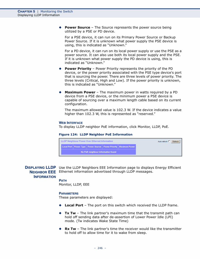
CHAPTER 5 | Monitoring the SwitchDisplaying LLDP Information
◆ Power Source – The Source represents the power source being utilized by a PSE or PD device.
For a PSE device, it can run on its Primary Power Source or Backup Power Source. If it is unknown what power supply the PSE device is using, this is indicated as “Unknown.”
For a PD device, it can run on its local power supply or use the PSE as a power source. It can also use both its local power supply and the PSE. If it is unknown what power supply the PD device is using, this is indicated as “Unknown.”
◆ Power Priority – Power Priority represents the priority of the PD device, or the power priority associated with the PSE type device's port that is sourcing the power. There are three levels of power priority. The three levels (Critical, High and Low). If the power priority is unknown, this is indicated as “Unknown.”
◆ Maximum Power – The maximum power in watts required by a PD device from a PSE device, or the minimum power a PSE device is capable of sourcing over a maximum length cable based on its current configuration.
The maximum allowed value is 102.3 W. If the device indicates a value higher than 102.3 W, this is represented as “reserved.”
WEB INTERFACETo display LLDP neighbor PoE information, click Monitor, LLDP, PoE.
Figure 124: LLDP Neighbor PoE Information
DISPLAYING LLDPNEIGHBOR EEE
INFORMATION
Use the LLDP Neighbors EEE Information page to displays Energy Efficient Ethernet information advertised through LLDP messages.
PATH Monitor, LLDP, EEE
PARAMETERSThese parameters are displayed:
◆ Local Port – The port on this switch which received the LLDP frame.
◆ Tx Tw – The link partner's maximum time that the transmit path can hold off sending data after de-assertion of Lower Power Idle (LPI) mode. (Tw indicates Wake State Time)
◆ Rx Tw – The link partner's time the receiver would like the transmitter to hold off to allow time for it to wake from sleep.
– 246 –
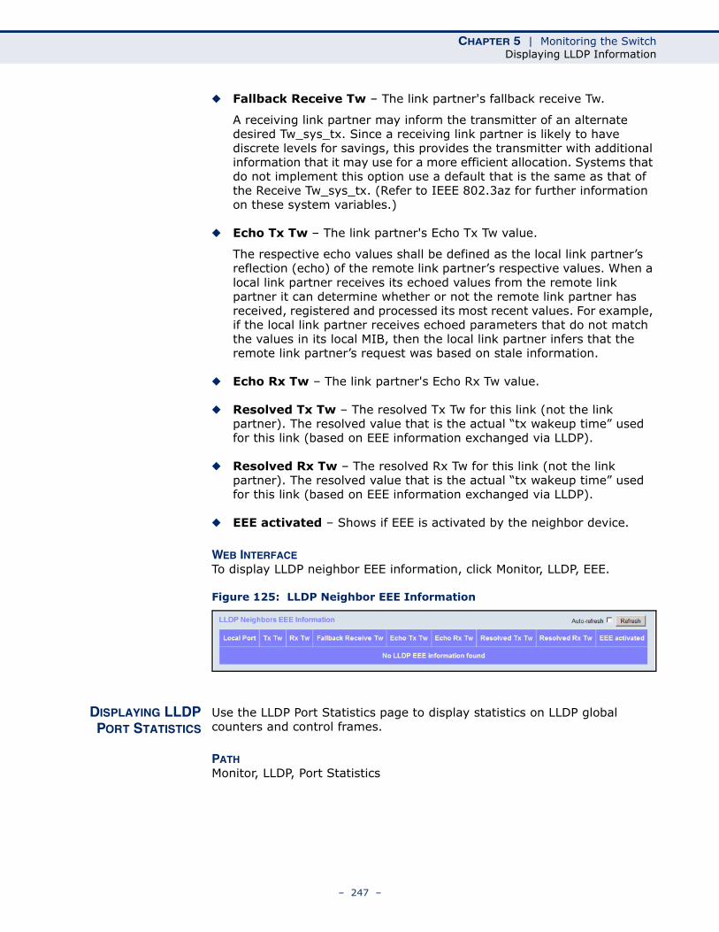
CHAPTER 5 | Monitoring the SwitchDisplaying LLDP Information
◆ Fallback Receive Tw – The link partner's fallback receive Tw.
A receiving link partner may inform the transmitter of an alternate desired Tw_sys_tx. Since a receiving link partner is likely to have discrete levels for savings, this provides the transmitter with additional information that it may use for a more efficient allocation. Systems that do not implement this option use a default that is the same as that of the Receive Tw_sys_tx. (Refer to IEEE 802.3az for further information on these system variables.)
◆ Echo Tx Tw – The link partner's Echo Tx Tw value.
The respective echo values shall be defined as the local link partner’s reflection (echo) of the remote link partner’s respective values. When a local link partner receives its echoed values from the remote link partner it can determine whether or not the remote link partner has received, registered and processed its most recent values. For example, if the local link partner receives echoed parameters that do not match the values in its local MIB, then the local link partner infers that the remote link partner’s request was based on stale information.
◆ Echo Rx Tw – The link partner's Echo Rx Tw value.
◆ Resolved Tx Tw – The resolved Tx Tw for this link (not the link partner). The resolved value that is the actual “tx wakeup time” used for this link (based on EEE information exchanged via LLDP).
◆ Resolved Rx Tw – The resolved Rx Tw for this link (not the link partner). The resolved value that is the actual “tx wakeup time” used for this link (based on EEE information exchanged via LLDP).
◆ EEE activated – Shows if EEE is activated by the neighbor device.
WEB INTERFACETo display LLDP neighbor EEE information, click Monitor, LLDP, EEE.
Figure 125: LLDP Neighbor EEE Information
DISPLAYING LLDPPORT STATISTICS
Use the LLDP Port Statistics page to display statistics on LLDP global counters and control frames.
PATH Monitor, LLDP, Port Statistics
– 247 –
CHAPTER 5 | Monitoring the SwitchDisplaying LLDP Information
PARAMETERSThese parameters are displayed:
Global Counters
◆ Neighbor entries were last changed at – The time the LLDP neighbor entry list was last updated. It also shows the time elapsed since last change was detected.
◆ Total Neighbors Entries Added – Shows the number of new entries added since the switch was rebooted, and for which the remote TTL has not yet expired.
◆ Total Neighbors Entries Deleted – The number of LLDP neighbors which have been removed from the LLDP remote systems MIB for any reason.
◆ Total Neighbors Entries Dropped – The number of times which the remote database on this switch dropped an LLDPDU because the entry table was full.
◆ Total Neighbors Entries Aged Out – The number of times that a neighbor’s information has been deleted from the LLDP remote systems MIB because the remote TTL timer has expired.
LLDP Statistics
◆ Local Port – Port Identifier.
◆ Tx Frames – Number of LLDP PDUs transmitted.
◆ Rx Frames – Number of LLDP PDUs received.
◆ Rx Errors – The number of received LLDP frames containing some kind of error.
◆ Frames Discarded – Number of frames discarded because they did not conform to the general validation rules as well as any specific usage rules defined for the particular Type Length Value (TLV).
◆ TLVs Discarded – Each LLDP frame can contain multiple pieces of information, known as TLVs. If a TLV is malformed, it is counted and discarded.
◆ TLVs Unrecognized – The number of well-formed TLVs, but with an unknown type value.
◆ Org. Discarded – The number of organizational TLVs discarded.
◆ Age-Outs – Each LLDP frame contains information about how long the LLDP information is valid (age-out time). If no new LLDP frame is received within the age-out time, the LLDP information is removed, and the Age-Out counter is incremented.
– 248 –
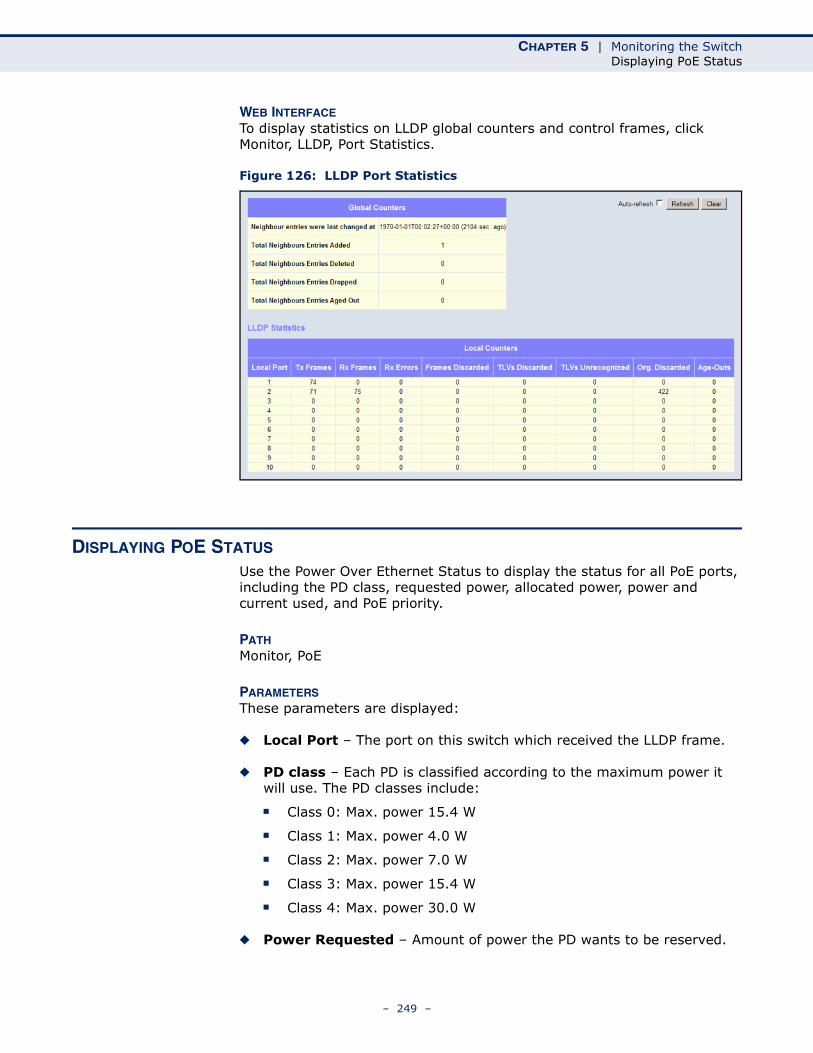
CHAPTER 5 | Monitoring the SwitchDisplaying PoE Status
WEB INTERFACETo display statistics on LLDP global counters and control frames, click Monitor, LLDP, Port Statistics.
Figure 126: LLDP Port Statistics
DISPLAYING POE STATUS
Use the Power Over Ethernet Status to display the status for all PoE ports, including the PD class, requested power, allocated power, power and current used, and PoE priority.
PATH Monitor, PoE
PARAMETERSThese parameters are displayed:
◆ Local Port – The port on this switch which received the LLDP frame.
◆ PD class – Each PD is classified according to the maximum power it will use. The PD classes include:
■ Class 0: Max. power 15.4 W
■ Class 1: Max. power 4.0 W
■ Class 2: Max. power 7.0 W
■ Class 3: Max. power 15.4 W
■ Class 4: Max. power 30.0 W
◆ Power Requested – Amount of power the PD wants to be reserved.
– 249 –
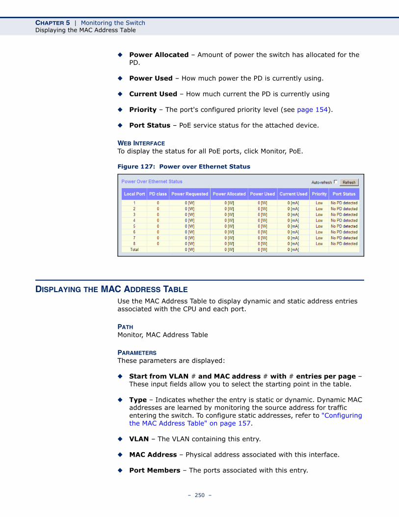
CHAPTER 5 | Monitoring the SwitchDisplaying the MAC Address Table
◆ Power Allocated – Amount of power the switch has allocated for the PD.
◆ Power Used – How much power the PD is currently using.
◆ Current Used – How much current the PD is currently using
◆ Priority – The port's configured priority level (see page 154).
◆ Port Status – PoE service status for the attached device.
WEB INTERFACETo display the status for all PoE ports, click Monitor, PoE.
Figure 127: Power over Ethernet Status
DISPLAYING THE MAC ADDRESS TABLE
Use the MAC Address Table to display dynamic and static address entries associated with the CPU and each port.
PATH Monitor, MAC Address Table
PARAMETERSThese parameters are displayed:
◆ Start from VLAN # and MAC address # with # entries per page – These input fields allow you to select the starting point in the table.
◆ Type – Indicates whether the entry is static or dynamic. Dynamic MAC addresses are learned by monitoring the source address for traffic entering the switch. To configure static addresses, refer to "Configuring the MAC Address Table" on page 157.
◆ VLAN – The VLAN containing this entry.
◆ MAC Address – Physical address associated with this interface.
◆ Port Members – The ports associated with this entry.
– 250 –
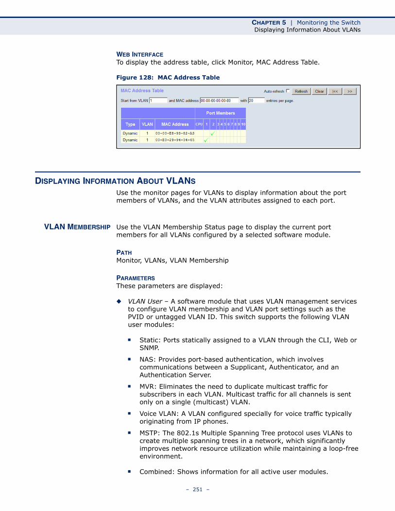
CHAPTER 5 | Monitoring the SwitchDisplaying Information About VLANs
WEB INTERFACETo display the address table, click Monitor, MAC Address Table.
Figure 128: MAC Address Table
DISPLAYING INFORMATION ABOUT VLANS
Use the monitor pages for VLANs to display information about the port members of VLANs, and the VLAN attributes assigned to each port.
VLAN MEMBERSHIP Use the VLAN Membership Status page to display the current port members for all VLANs configured by a selected software module.
PATH Monitor, VLANs, VLAN Membership
PARAMETERSThese parameters are displayed:
◆ VLAN User – A software module that uses VLAN management services to configure VLAN membership and VLAN port settings such as the PVID or untagged VLAN ID. This switch supports the following VLAN user modules:
■ Static: Ports statically assigned to a VLAN through the CLI, Web or SNMP.
■ NAS: Provides port-based authentication, which involves communications between a Supplicant, Authenticator, and an Authentication Server.
■ MVR: Eliminates the need to duplicate multicast traffic for subscribers in each VLAN. Multicast traffic for all channels is sent only on a single (multicast) VLAN.
■ Voice VLAN: A VLAN configured specially for voice traffic typically originating from IP phones.
■ MSTP: The 802.1s Multiple Spanning Tree protocol uses VLANs to create multiple spanning trees in a network, which significantly improves network resource utilization while maintaining a loop-free environment.
■ Combined: Shows information for all active user modules.
– 251 –
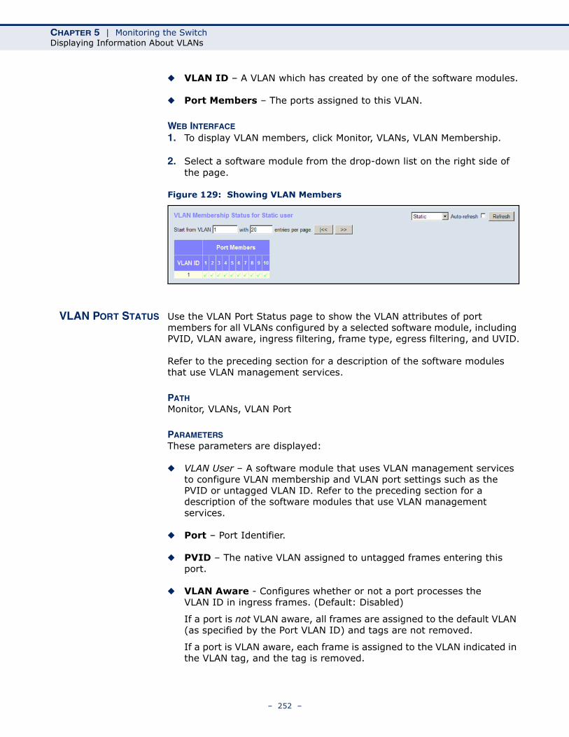
CHAPTER 5 | Monitoring the SwitchDisplaying Information About VLANs
◆ VLAN ID – A VLAN which has created by one of the software modules.
◆ Port Members – The ports assigned to this VLAN.
WEB INTERFACE
1. To display VLAN members, click Monitor, VLANs, VLAN Membership.
2. Select a software module from the drop-down list on the right side of the page.
Figure 129: Showing VLAN Members
VLAN PORT STATUS Use the VLAN Port Status page to show the VLAN attributes of port members for all VLANs configured by a selected software module, including PVID, VLAN aware, ingress filtering, frame type, egress filtering, and UVID.
Refer to the preceding section for a description of the software modules that use VLAN management services.
PATH Monitor, VLANs, VLAN Port
PARAMETERSThese parameters are displayed:
◆ VLAN User – A software module that uses VLAN management services to configure VLAN membership and VLAN port settings such as the PVID or untagged VLAN ID. Refer to the preceding section for a description of the software modules that use VLAN management services.
◆ Port – Port Identifier.
◆ PVID – The native VLAN assigned to untagged frames entering this port.
◆ VLAN Aware - Configures whether or not a port processes the VLAN ID in ingress frames. (Default: Disabled)
If a port is not VLAN aware, all frames are assigned to the default VLAN (as specified by the Port VLAN ID) and tags are not removed.
If a port is VLAN aware, each frame is assigned to the VLAN indicated in the VLAN tag, and the tag is removed.
– 252 –
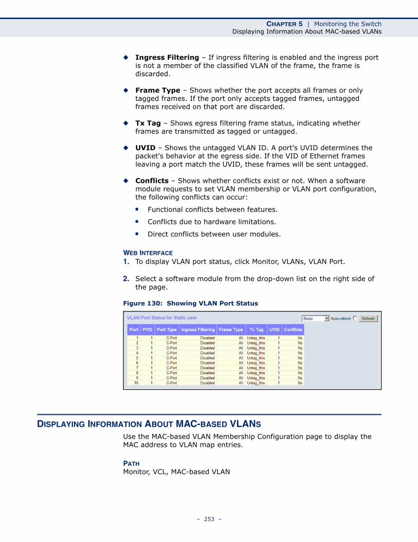
CHAPTER 5 | Monitoring the SwitchDisplaying Information About MAC-based VLANs
◆ Ingress Filtering – If ingress filtering is enabled and the ingress port is not a member of the classified VLAN of the frame, the frame is discarded.
◆ Frame Type – Shows whether the port accepts all frames or only tagged frames. If the port only accepts tagged frames, untagged frames received on that port are discarded.
◆ Tx Tag – Shows egress filtering frame status, indicating whether frames are transmitted as tagged or untagged.
◆ UVID – Shows the untagged VLAN ID. A port's UVID determines the packet's behavior at the egress side. If the VID of Ethernet frames leaving a port match the UVID, these frames will be sent untagged.
◆ Conflicts – Shows whether conflicts exist or not. When a software module requests to set VLAN membership or VLAN port configuration, the following conflicts can occur:
■ Functional conflicts between features.
■ Conflicts due to hardware limitations.
■ Direct conflicts between user modules.
WEB INTERFACE
1. To display VLAN port status, click Monitor, VLANs, VLAN Port.
2. Select a software module from the drop-down list on the right side of the page.
Figure 130: Showing VLAN Port Status
DISPLAYING INFORMATION ABOUT MAC-BASED VLANS
Use the MAC-based VLAN Membership Configuration page to display the MAC address to VLAN map entries.
PATH Monitor, VCL, MAC-based VLAN
– 253 –
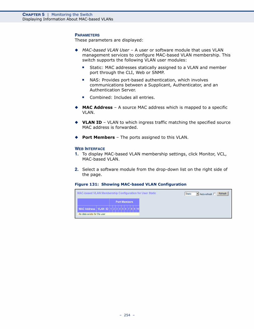
CHAPTER 5 | Monitoring the SwitchDisplaying Information About MAC-based VLANs
PARAMETERSThese parameters are displayed:
◆ MAC-based VLAN User – A user or software module that uses VLAN management services to configure MAC-based VLAN membership. This switch supports the following VLAN user modules:
■ Static: MAC addresses statically assigned to a VLAN and member port through the CLI, Web or SNMP.
■ NAS: Provides port-based authentication, which involves communications between a Supplicant, Authenticator, and an Authentication Server.
■ Combined: Includes all entries.
◆ MAC Address – A source MAC address which is mapped to a specific VLAN.
◆ VLAN ID – VLAN to which ingress traffic matching the specified source MAC address is forwarded.
◆ Port Members – The ports assigned to this VLAN.
WEB INTERFACE
1. To display MAC-based VLAN membership settings, click Monitor, VCL, MAC-based VLAN.
2. Select a software module from the drop-down list on the right side of the page.
Figure 131: Showing MAC-based VLAN Configuration
– 254 –
6 PERFORMING BASIC DIAGNOSTICS
This chapter describes how to test network connectivity using Ping for IPv4 or IPv6, and how to test network cables.
PINGING AN IPV4 OR IPV6 ADDRESS
The Ping page is used to send ICMP echo request packets to another node on the network to determine if it can be reached.
PATH◆ Diagnostics, Ping◆ Diagnostics, Ping6
PARAMETERSThese parameters are displayed on the Ping page:
◆ IP Address – IPv4 or IPv6 address of the host.
An IPv4 address consists of 4 numbers, 0 to 255, separated by periods.
An IPv6 address consists of 8 colon-separated 16-bit hexadecimal values. One double colon may be used in the address to indicate the appropriate number of zeros required to fill the undefined fields.
◆ Ping Size – The payload size of the ICMP packet. (Range: 8- 1400 bytes)
WEB INTERFACETo ping another device on the network:
1. Click Diagnostics, Ping or Ping6.
2. Enter the IP address of the target device.
3. Specify the packet size.
4. Click Start.
After you press Start, five ICMP packets are transmitted, and the sequence number and round-trip time are displayed upon reception of a reply. The page refreshes automatically until responses to all packets are received, or until a timeout occurs.
– 255 –
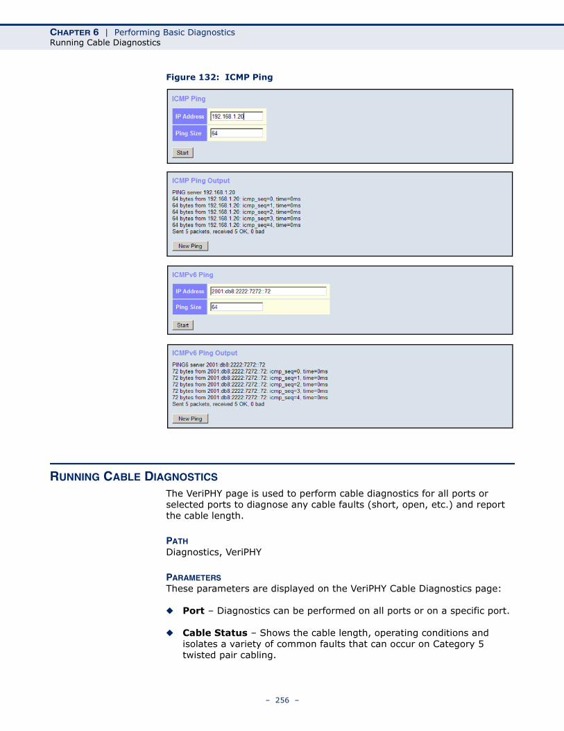
CHAPTER 6 | Performing Basic DiagnosticsRunning Cable Diagnostics
Figure 132: ICMP Ping
RUNNING CABLE DIAGNOSTICS
The VeriPHY page is used to perform cable diagnostics for all ports or selected ports to diagnose any cable faults (short, open, etc.) and report the cable length.
PATHDiagnostics, VeriPHY
PARAMETERSThese parameters are displayed on the VeriPHY Cable Diagnostics page:
◆ Port – Diagnostics can be performed on all ports or on a specific port.
◆ Cable Status – Shows the cable length, operating conditions and isolates a variety of common faults that can occur on Category 5 twisted pair cabling.
– 256 –
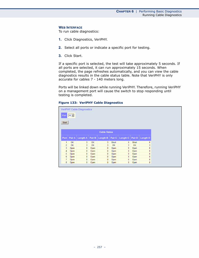
CHAPTER 6 | Performing Basic DiagnosticsRunning Cable Diagnostics
WEB INTERFACETo run cable diagnostics:
1. Click Diagnostics, VeriPHY.
2. Select all ports or indicate a specific port for testing.
3. Click Start.
If a specific port is selected, the test will take approximately 5 seconds. If all ports are selected, it can run approximately 15 seconds. When completed, the page refreshes automatically, and you can view the cable diagnostics results in the cable status table. Note that VeriPHY is only accurate for cables 7 - 140 meters long.
Ports will be linked down while running VeriPHY. Therefore, running VeriPHY on a management port will cause the switch to stop responding until testing is completed.
Figure 133: VeriPHY Cable Diagnostics
– 257 –

CHAPTER 6 | Performing Basic DiagnosticsRunning Cable Diagnostics
– 258 –
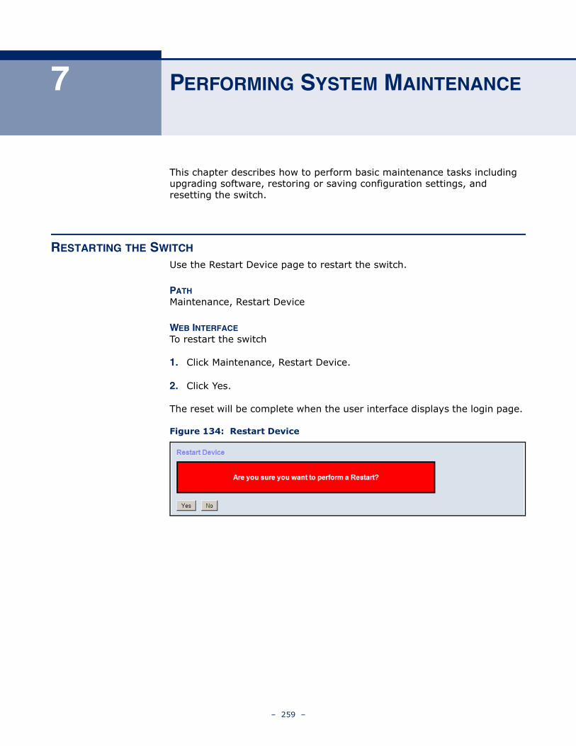
7 PERFORMING SYSTEM MAINTENANCE
This chapter describes how to perform basic maintenance tasks including upgrading software, restoring or saving configuration settings, and resetting the switch.
RESTARTING THE SWITCH
Use the Restart Device page to restart the switch.
PATHMaintenance, Restart Device
WEB INTERFACETo restart the switch
1. Click Maintenance, Restart Device.
2. Click Yes.
The reset will be complete when the user interface displays the login page.
Figure 134: Restart Device
– 259 –
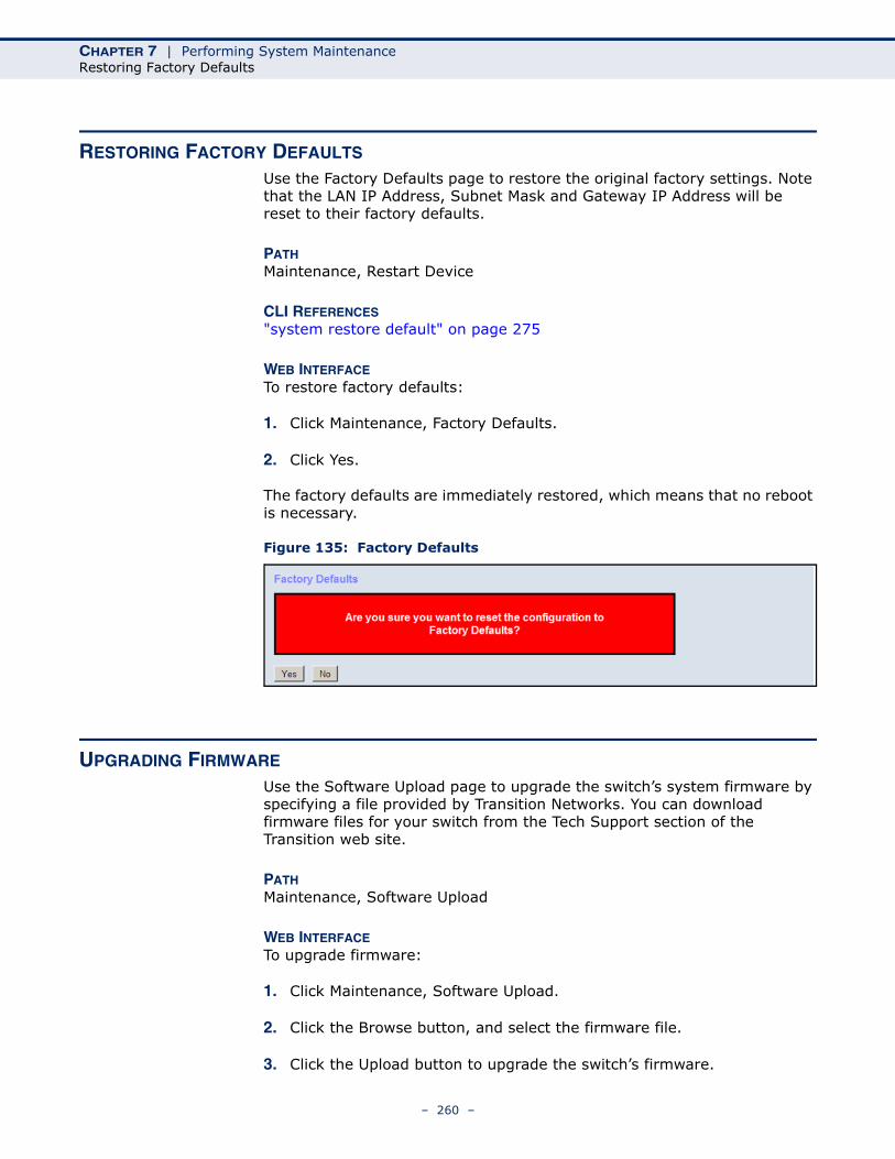
CHAPTER 7 | Performing System MaintenanceRestoring Factory Defaults
RESTORING FACTORY DEFAULTS
Use the Factory Defaults page to restore the original factory settings. Note that the LAN IP Address, Subnet Mask and Gateway IP Address will be reset to their factory defaults.
PATHMaintenance, Restart Device
CLI REFERENCES"system restore default" on page 275
WEB INTERFACETo restore factory defaults:
1. Click Maintenance, Factory Defaults.
2. Click Yes.
The factory defaults are immediately restored, which means that no reboot is necessary.
Figure 135: Factory Defaults
UPGRADING FIRMWARE
Use the Software Upload page to upgrade the switch’s system firmware by specifying a file provided by Transition Networks. You can download firmware files for your switch from the Tech Support section of the Transition web site.
PATHMaintenance, Software Upload
WEB INTERFACETo upgrade firmware:
1. Click Maintenance, Software Upload.
2. Click the Browse button, and select the firmware file.
3. Click the Upload button to upgrade the switch’s firmware.
– 260 –
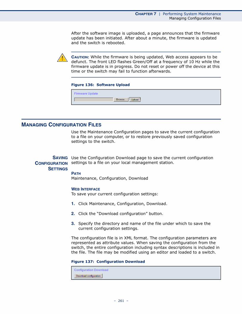
CHAPTER 7 | Performing System MaintenanceManaging Configuration Files
After the software image is uploaded, a page announces that the firmware update has been initiated. After about a minute, the firmware is updated and the switch is rebooted.
CAUTION: While the firmware is being updated, Web access appears to be defunct. The front LED flashes Green/Off at a frequency of 10 Hz while the firmware update is in progress. Do not reset or power off the device at this time or the switch may fail to function afterwards.
Figure 136: Software Upload
MANAGING CONFIGURATION FILES
Use the Maintenance Configuration pages to save the current configuration to a file on your computer, or to restore previously saved configuration settings to the switch.
SAVINGCONFIGURATION
SETTINGS
Use the Configuration Download page to save the current configuration settings to a file on your local management station.
PATHMaintenance, Configuration, Download
WEB INTERFACETo save your current configuration settings:
1. Click Maintenance, Configuration, Download.
2. Click the “Download configuration” button.
3. Specify the directory and name of the file under which to save the current configuration settings.
The configuration file is in XML format. The configuration parameters are represented as attribute values. When saving the configuration from the switch, the entire configuration including syntax descriptions is included in the file. The file may be modified using an editor and loaded to a switch.
Figure 137: Configuration Download
– 261 –
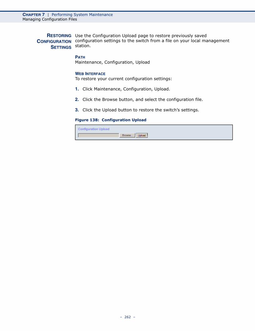
CHAPTER 7 | Performing System MaintenanceManaging Configuration Files
RESTORINGCONFIGURATION
SETTINGS
Use the Configuration Upload page to restore previously saved configuration settings to the switch from a file on your local management station.
PATHMaintenance, Configuration, Upload
WEB INTERFACETo restore your current configuration settings:
1. Click Maintenance, Configuration, Upload.
2. Click the Browse button, and select the configuration file.
3. Click the Upload button to restore the switch’s settings.
Figure 138: Configuration Upload
– 262 –
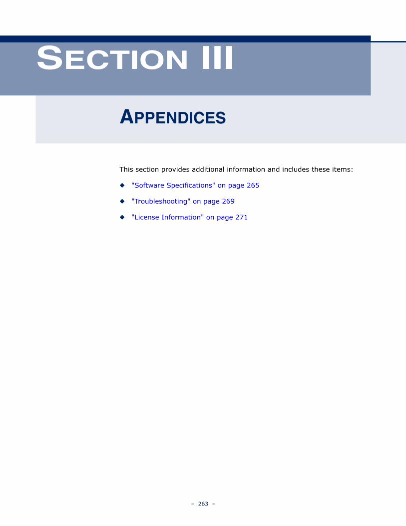
SECTION III
APPENDICES
This section provides additional information and includes these items:
◆ "Software Specifications" on page 265
◆ "Troubleshooting" on page 269
◆ "License Information" on page 271
– 263 –

SECTION III | Appendices
– 264 –
A SOFTWARE SPECIFICATIONS
SOFTWARE FEATURES
MANAGEMENT
AUTHENTICATION
Local, RADIUS, TACACS+, AAA, Port Authentication (802.1X), HTTPS, SSH, Port Security, IP Filter, DHCP Snooping
CLIENT ACCESSCONTROL
Access Control Lists (128 rules per system), Port Authentication (802.1X), MAC Authentication, Port Security, DHCP Snooping, IP Source Guard, ARP Inspection
PORT CONFIGURATION 100BASE-TX: 10/100 Mbps, half/full duplex100BASE-FX: 100 Mbps at full duplex (SFP)1000BASE-T: 10/100 Mbps at half/full duplex, 1000 Mbps at full duplex1000BASE-SX/LX/LH - 1000 Mbps at full duplex (SFP)
FLOW CONTROL Full Duplex: IEEE 802.3-2005Half Duplex: Back pressure
STORM CONTROL Broadcast, multicast, or unicast traffic throttled above a critical threshold
PORT MIRRORING 10 sessions, one source port to one destination port
RATE LIMITS Input limits per port (manual setting or ACL)
PORT TRUNKING Static trunks (Cisco EtherChannel compliant)Dynamic trunks (Link Aggregation Control Protocol)
SPANNING TREEALGORITHM
Spanning Tree Protocol (STP, IEEE 802.1D-2004) Rapid Spanning Tree Protocol (RSTP, IEEE 802.1D-2004) Multiple Spanning Tree Protocol (MSTP, IEEE 802.1D-2004)
– 265 –
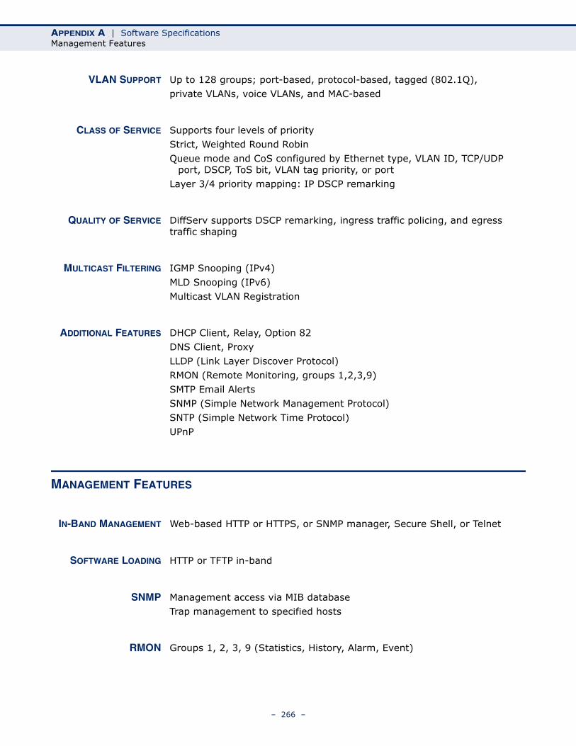
APPENDIX A | Software SpecificationsManagement Features
VLAN SUPPORT Up to 128 groups; port-based, protocol-based, tagged (802.1Q),private VLANs, voice VLANs, and MAC-based
CLASS OF SERVICE Supports four levels of priorityStrict, Weighted Round Robin Queue mode and CoS configured by Ethernet type, VLAN ID, TCP/UDP
port, DSCP, ToS bit, VLAN tag priority, or portLayer 3/4 priority mapping: IP DSCP remarking
QUALITY OF SERVICE DiffServ supports DSCP remarking, ingress traffic policing, and egress traffic shaping
MULTICAST FILTERING IGMP Snooping (IPv4)MLD Snooping (IPv6)Multicast VLAN Registration
ADDITIONAL FEATURES DHCP Client, Relay, Option 82DNS Client, ProxyLLDP (Link Layer Discover Protocol)RMON (Remote Monitoring, groups 1,2,3,9)SMTP Email AlertsSNMP (Simple Network Management Protocol)SNTP (Simple Network Time Protocol)UPnP
MANAGEMENT FEATURES
IN-BAND MANAGEMENT Web-based HTTP or HTTPS, or SNMP manager, Secure Shell, or Telnet
SOFTWARE LOADING HTTP or TFTP in-band
SNMP Management access via MIB databaseTrap management to specified hosts
RMON Groups 1, 2, 3, 9 (Statistics, History, Alarm, Event)
– 266 –
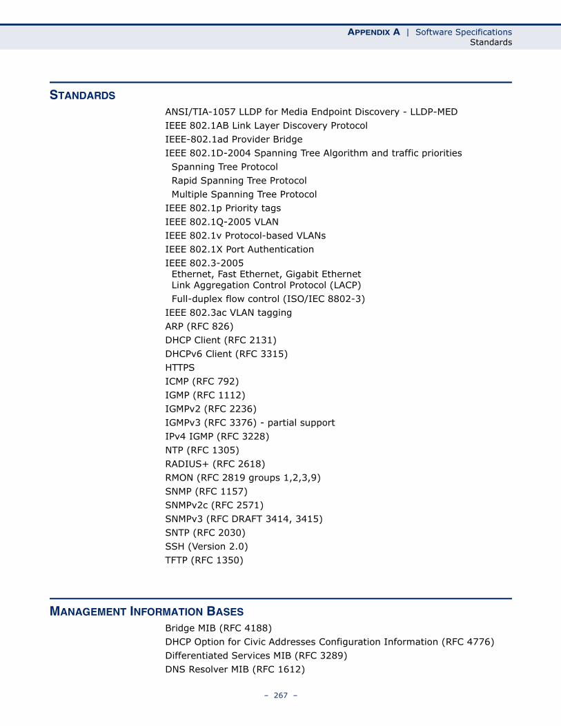
APPENDIX A | Software SpecificationsStandards
STANDARDS
ANSI/TIA-1057 LLDP for Media Endpoint Discovery - LLDP-MEDIEEE 802.1AB Link Layer Discovery ProtocolIEEE-802.1ad Provider BridgeIEEE 802.1D-2004 Spanning Tree Algorithm and traffic priorities Spanning Tree Protocol Rapid Spanning Tree Protocol Multiple Spanning Tree ProtocolIEEE 802.1p Priority tagsIEEE 802.1Q-2005 VLANIEEE 802.1v Protocol-based VLANsIEEE 802.1X Port AuthenticationIEEE 802.3-2005 Ethernet, Fast Ethernet, Gigabit Ethernet Link Aggregation Control Protocol (LACP) Full-duplex flow control (ISO/IEC 8802-3)IEEE 802.3ac VLAN taggingARP (RFC 826)DHCP Client (RFC 2131)DHCPv6 Client (RFC 3315)HTTPSICMP (RFC 792)IGMP (RFC 1112)IGMPv2 (RFC 2236)IGMPv3 (RFC 3376) - partial supportIPv4 IGMP (RFC 3228)NTP (RFC 1305)RADIUS+ (RFC 2618)RMON (RFC 2819 groups 1,2,3,9)SNMP (RFC 1157)SNMPv2c (RFC 2571)SNMPv3 (RFC DRAFT 3414, 3415)SNTP (RFC 2030)SSH (Version 2.0)TFTP (RFC 1350)
MANAGEMENT INFORMATION BASES
Bridge MIB (RFC 4188)DHCP Option for Civic Addresses Configuration Information (RFC 4776)Differentiated Services MIB (RFC 3289)DNS Resolver MIB (RFC 1612)
– 267 –
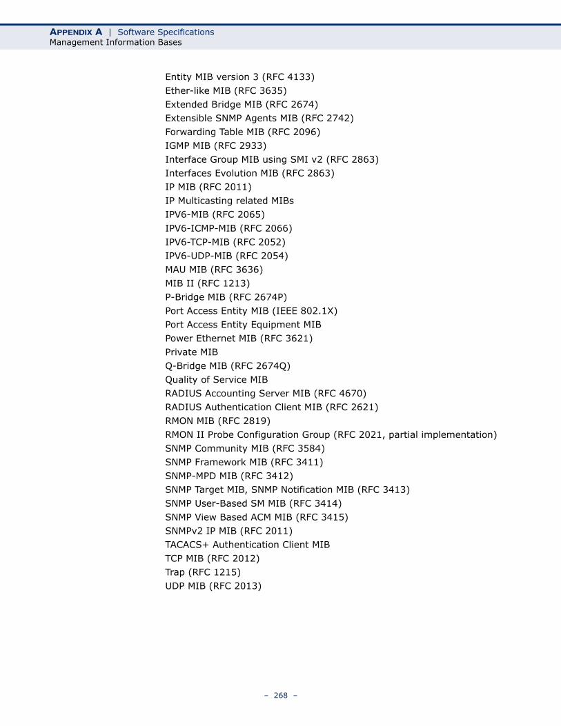
APPENDIX A | Software SpecificationsManagement Information Bases
Entity MIB version 3 (RFC 4133)Ether-like MIB (RFC 3635)Extended Bridge MIB (RFC 2674)Extensible SNMP Agents MIB (RFC 2742)Forwarding Table MIB (RFC 2096)IGMP MIB (RFC 2933)Interface Group MIB using SMI v2 (RFC 2863)Interfaces Evolution MIB (RFC 2863)IP MIB (RFC 2011)IP Multicasting related MIBs IPV6-MIB (RFC 2065)
IPV6-ICMP-MIB (RFC 2066)IPV6-TCP-MIB (RFC 2052)IPV6-UDP-MIB (RFC 2054)MAU MIB (RFC 3636)MIB II (RFC 1213)P-Bridge MIB (RFC 2674P)Port Access Entity MIB (IEEE 802.1X)Port Access Entity Equipment MIBPower Ethernet MIB (RFC 3621)Private MIBQ-Bridge MIB (RFC 2674Q)Quality of Service MIBRADIUS Accounting Server MIB (RFC 4670)RADIUS Authentication Client MIB (RFC 2621)RMON MIB (RFC 2819)RMON II Probe Configuration Group (RFC 2021, partial implementation)SNMP Community MIB (RFC 3584)SNMP Framework MIB (RFC 3411)SNMP-MPD MIB (RFC 3412)SNMP Target MIB, SNMP Notification MIB (RFC 3413)SNMP User-Based SM MIB (RFC 3414)SNMP View Based ACM MIB (RFC 3415)SNMPv2 IP MIB (RFC 2011)TACACS+ Authentication Client MIBTCP MIB (RFC 2012)Trap (RFC 1215)UDP MIB (RFC 2013)
– 268 –

B TROUBLESHOOTING
PROBLEMS ACCESSING THE MANAGEMENT INTERFACE
Table 14: Troubleshooting Chart
Symptom Action
Cannot connect using a web browser, or SNMP software
◆ Be sure the switch is powered up.
◆ Check network cabling between the management station and the switch.
◆ Check that you have a valid network connection to the switch and that the port you are using has not been disabled.
◆ Be sure you have configured the VLAN interface through which the management station is connected with a valid IP address, subnet mask and default gateway.
◆ Be sure the management station has an IP address in the same subnet as the switch’s IP interface to which it is connected.
◆ If you are trying to connect to the switch via the IP address for a tagged VLAN group, your management station, and the ports connecting intermediate switches in the network, must be configured with the appropriate tag.
Forgot or lost the password
◆ Contact your local distributor.
– 269 –
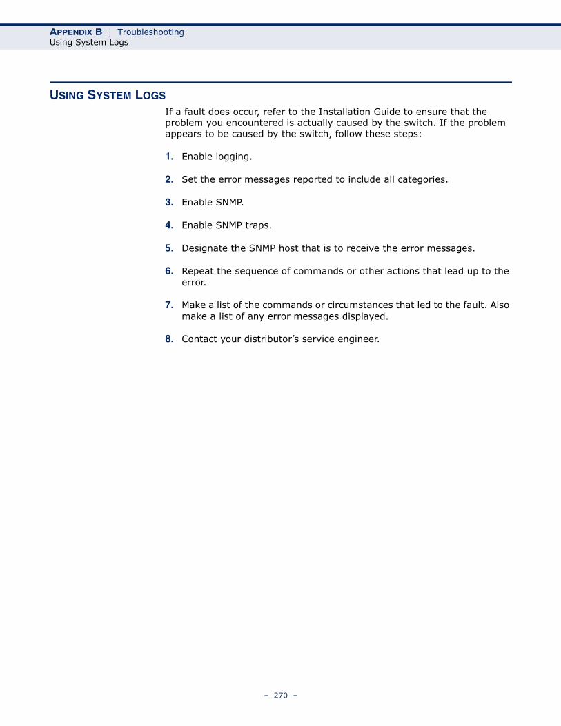
APPENDIX B | TroubleshootingUsing System Logs
USING SYSTEM LOGS
If a fault does occur, refer to the Installation Guide to ensure that the problem you encountered is actually caused by the switch. If the problem appears to be caused by the switch, follow these steps:
1. Enable logging.
2. Set the error messages reported to include all categories.
3. Enable SNMP.
4. Enable SNMP traps.
5. Designate the SNMP host that is to receive the error messages.
6. Repeat the sequence of commands or other actions that lead up to the error.
7. Make a list of the commands or circumstances that led to the fault. Also make a list of any error messages displayed.
8. Contact your distributor’s service engineer.
– 270 –
C LICENSE INFORMATION
This product includes copyrighted third-party software subject to the terms of the GNU General Public License (GPL), GNU Lesser General Public License (LGPL), or other related free software licenses. The GPL code used in this product is distributed WITHOUT ANY WARRANTY and is subject to the copyrights of one or more authors. For details, refer to the section "The GNU General Public License" below, or refer to the applicable license as included in the source-code archive.
THE GNU GENERAL PUBLIC LICENSE
GNU GENERAL PUBLIC LICENSEVersion 2, June 1991
Copyright (C) 1989, 1991 Free Software Foundation, Inc.59 Temple Place, Suite 330, Boston, MA 02111-1307 USA
Everyone is permitted to copy and distribute verbatim copies of this license document, but changing it is not allowed.
Preamble
The licenses for most software are designed to take away your freedom to share and change it. By contrast, the GNU General Public License is intended to guarantee your freedom to share and change free software--to make sure the software is free for all its users. This General Public License applies to most of the Free Software Foundation's software and to any other program whose authors commit to using it. (Some other Free Software Foundation software is covered by the GNU Library General Public License instead.) You can apply it to your programs, too.
When we speak of free software, we are referring to freedom, not price. Our General Public Licenses are designed to make sure that you have the freedom to distribute copies of free software (and charge for this service if you wish), that you receive source code or can get it if you want it, that you can change the software or use pieces of it in new free programs; and that you know you can do these things.
To protect your rights, we need to make restrictions that forbid anyone to deny you these rights or to ask you to surrender the rights. These restrictions translate to certain responsibilities for you if you distribute copies of the software, or if you modify it.
For example, if you distribute copies of such a program, whether gratis or for a fee, you must give the recipients all the rights that you have. You must make sure that they, too, receive or can get the source code. And you must show them these terms so they know their rights.
We protect your rights with two steps: (1) copyright the software, and (2) offer you this license which gives you legal permission to copy, distribute and/or modify the software.
Also, for each author's protection and ours, we want to make certain that everyone understands that there is no warranty for this free software. If the software is modified by someone else and passed on, we want its recipients to know that what they have is not the original, so that any problems introduced by others will not reflect on the original authors' reputations.
Finally, any free program is threatened constantly by software patents. We wish to avoid the danger that redistributors of a free program will individually obtain patent licenses, in effect making the program proprietary. To prevent this, we have made it clear that any patent must be licensed for everyone's free use or not licensed at all.
The precise terms and conditions for copying, distribution and modification follow.
– 271 –
APPENDIX C | License InformationThe GNU General Public License
GNU GENERAL PUBLIC LICENSE TERMS AND CONDITIONS FOR COPYING, DISTRIBUTION AND MODIFICATION
1. This License applies to any program or other work which contains a notice placed by the copyright holder saying it may be distributed under the terms of this General Public License. The "Program", below, refers to any such program or work, and a "work based on the Program" means either the Program or any derivative work under copyright law: that is to say, a work containing the Program or a portion of it, either verbatim or with modifications and/or translated into another language. (Hereinafter, translation is included without limitation in the term "modification".) Each licensee is addressed as "you".
Activities other than copying, distribution and modification are not covered by this License; they are outside its scope. The act of running the Program is not restricted, and the output from the Program is covered only if its contents constitute a work based on the Program (independent of having been made by running the Program). Whether that is true depends on what the Program does.
2. You may copy and distribute verbatim copies of the Program's source code as you receive it, in any medium, provided that you conspicuously and appropriately publish on each copy an appropriate copyright notice and disclaimer of warranty; keep intact all the notices that refer to this License and to the absence of any warranty; and give any other recipients of the Program a copy of this License along with the Program.
You may charge a fee for the physical act of transferring a copy, and you may at your option offer warranty protection in exchange for a fee.
3. You may modify your copy or copies of the Program or any portion of it, thus forming a work based on the Program, and copy and distribute such modifications or work under the terms of Section 1 above, provided that you also meet all of these conditions:
a). You must cause the modified files to carry prominent notices stating that you changed the files and the date of any change.
b). You must cause any work that you distribute or publish, that in whole or in part contains or is derived from the Program or any part thereof, to be licensed as a whole at no charge to all third parties under the terms of this License.
c). If the modified program normally reads commands interactively when run, you must cause it, when started running for such interactive use in the most ordinary way, to print or display an announcement including an appropriate copyright notice and a notice that there is no warranty (or else, saying that you provide a warranty) and that users may redistribute the program under these conditions, and telling the user how to view a copy of this License. (Exception: if the Program itself is interactive but does not normally print such an announcement, your work based on the Program is not required to print an announcement.)
These requirements apply to the modified work as a whole. If identifiable sections of that work are not derived from the Program, and can be reasonably considered independent and separate works in themselves, then this License, and its terms, do not apply to those sections when you distribute them as separate works. But when you distribute the same sections as part of a whole which is a work based on the Program, the distribution of the whole must be on the terms of this License, whose permissions for other licensees extend to the entire whole, and thus to each and every part regardless of who wrote it.
Thus, it is not the intent of this section to claim rights or contest your rights to work written entirely by you; rather, the intent is to exercise the right to control the distribution of derivative or collective works based on the Program.
In addition, mere aggregation of another work not based on the Program with the Program (or with a work based on the Program) on a volume of a storage or distribution medium does not bring the other work under the scope of this License.
4. You may copy and distribute the Program (or a work based on it, under Section 2) in object code or executable form under the terms of Sections 1 and 2 above provided that you also do one of the following:
a). Accompany it with the complete corresponding machine-readable source code, which must be distributed under the terms of Sections 1 and 2 above on a medium customarily used for software interchange; or,
– 272 –
APPENDIX C | License InformationThe GNU General Public License
b). Accompany it with a written offer, valid for at least three years, to give any third party, for a charge no more than your cost of physically performing source distribution, a complete machine-readable copy of the corresponding source code, to be distributed under the terms of Sections 1 and 2 above on a medium customarily used for software interchange; or,
c). Accompany it with the information you received as to the offer to distribute corresponding source code. (This alternative is allowed only for noncommercial distribution and only if you received the program in object code or executable form with such an offer, in accord with Subsection b above.)
The source code for a work means the preferred form of the work for making modifications to it. For an executable work, complete source code means all the source code for all modules it contains, plus any associated interface definition files, plus the scripts used to control compilation and installation of the executable. However, as a special exception, the source code distributed need not include anything that is normally distributed (in either source or binary form) with the major components (compiler, kernel, and so on) of the operating system on which the executable runs, unless that component itself accompanies the executable.
If distribution of executable or object code is made by offering access to copy from a designated place, then offering equivalent access to copy the source code from the same place counts as distribution of the source code, even though third parties are not compelled to copy the source along with the object code.
5. You may not copy, modify, sublicense, or distribute the Program except as expressly provided under this License. Any attempt otherwise to copy, modify, sublicense or distribute the Program is void, and will automatically terminate your rights under this License. However, parties who have received copies, or rights, from you under this License will not have their licenses terminated so long as such parties remain in full compliance.
6. You are not required to accept this License, since you have not signed it. However, nothing else grants you permission to modify or distribute the Program or its derivative works. These actions are prohibited by law if you do not accept this License. Therefore, by modifying or distributing the Program (or any work based on the Program), you indicate your acceptance of this License to do so, and all its terms and conditions for copying, distributing or modifying the Program or works based on it.
7. Each time you redistribute the Program (or any work based on the Program), the recipient automatically receives a license from the original licensor to copy, distribute or modify the Program subject to these terms and conditions. You may not impose any further restrictions on the recipients' exercise of the rights granted herein. You are not responsible for enforcing compliance by third parties to this License.
8. If, as a consequence of a court judgment or allegation of patent infringement or for any other reason (not limited to patent issues), conditions are imposed on you (whether by court order, agreement or otherwise) that contradict the conditions of this License, they do not excuse you from the conditions of this License. If you cannot distribute so as to satisfy simultaneously your obligations under this License and any other pertinent obligations, then as a consequence you may not distribute the Program at all. For example, if a patent license would not permit royalty-free redistribution of the Program by all those who receive copies directly or indirectly through you, then the only way you could satisfy both it and this License would be to refrain entirely from distribution of the Program.
If any portion of this section is held invalid or unenforceable under any particular circumstance, the balance of the section is intended to apply and the section as a whole is intended to apply in other circumstances.
It is not the purpose of this section to induce you to infringe any patents or other property right claims or to contest validity of any such claims; this section has the sole purpose of protecting the integrity of the free software distribution system, which is implemented by public license practices. Many people have made generous contributions to the wide range of software distributed through that system in reliance on consistent application of that system; it is up to the author/donor to decide if he or she is willing to distribute software through any other system and a licensee cannot impose that choice.
This section is intended to make thoroughly clear what is believed to be a consequence of the rest of this License.
– 273 –

APPENDIX C | License InformationThe GNU General Public License
9. If the distribution and/or use of the Program is restricted in certain countries either by patents or by copyrighted interfaces, the original copyright holder who places the Program under this License may add an explicit geographical distribution limitation excluding those countries, so that distribution is permitted only in or among countries not thus excluded. In such case, this License incorporates the limitation as if written in the body of this License.
10. The Free Software Foundation may publish revised and/or new versions of the General Public License from time to time. Such new versions will be similar in spirit to the present version, but may differ in detail to address new problems or concerns.
Each version is given a distinguishing version number. If the Program specifies a version number of this License which applies to it and "any later version", you have the option of following the terms and conditions either of that version or of any later version published by the Free Software Foundation. If the Program does not specify a version number of this License, you may choose any version ever published by the Free Software Foundation.
11. If you wish to incorporate parts of the Program into other free programs whose distribution conditions are different, write to the author to ask for permission. For software which is copyrighted by the Free Software Foundation, write to the Free Software Foundation; we sometimes make exceptions for this. Our decision will be guided by the two goals of preserving the free status of all derivatives of our free software and of promoting the sharing and reuse of software generally.
NO WARRANTY
1. BECAUSE THE PROGRAM IS LICENSED FREE OF CHARGE, THERE IS NO WARRANTY FOR THE PROGRAM, TO THE EXTENT PERMITTED BY APPLICABLE LAW. EXCEPT WHEN OTHERWISE STATED IN WRITING THE COPYRIGHT HOLDERS AND/OR OTHER PARTIES PROVIDE THE PROGRAM "AS IS" WITHOUT WARRANTY OF ANY KIND, EITHER EXPRESSED OR IMPLIED, INCLUDING, BUT NOT LIMITED TO, THE IMPLIED WARRANTIES OF MERCHANTABILITY AND FITNESS FOR A PARTICULAR PURPOSE. THE ENTIRE RISK AS TO THE QUALITY AND PERFORMANCE OF THE PROGRAM IS WITH YOU. SHOULD THE PROGRAM PROVE DEFECTIVE, YOU ASSUME THE COST OF ALL NECESSARY SERVICING, REPAIR OR CORRECTION.
2. IN NO EVENT UNLESS REQUIRED BY APPLICABLE LAW OR AGREED TO IN WRITING WILL ANY COPYRIGHT HOLDER, OR ANY OTHER PARTY WHO MAY MODIFY AND/OR REDISTRIBUTE THE PROGRAM AS PERMITTED ABOVE, BE LIABLE TO YOU FOR DAMAGES, INCLUDING ANY GENERAL, SPECIAL, INCIDENTAL OR CONSEQUENTIAL DAMAGES ARISING OUT OF THE USE OR INABILITY TO USE THE PROGRAM (INCLUDING BUT NOT LIMITED TO LOSS OF DATA OR DATA BEING RENDERED INACCURATE OR LOSSES SUSTAINED BY YOU OR THIRD PARTIES OR A FAILURE OF THE PROGRAM TO OPERATE WITH ANY OTHER PROGRAMS), EVEN IF SUCH HOLDER OR OTHER PARTY HAS BEEN ADVISED OF THE POSSIBILITY OF SUCH DAMAGES.
END OF TERMS AND CONDITIONS
– 274 –
GLOSSARY
ACL Access Control List. ACLs can limit network traffic and restrict access to certain users or devices by checking each packet for certain IP or MAC (i.e., Layer 2) information.
ARP Address Resolution Protocol converts between IP addresses and MAC (hardware) addresses. ARP is used to locate the MAC address corresponding to a given IP address. This allows the switch to use IP addresses for routing decisions and the corresponding MAC addresses to forward packets from one hop to the next.
COS Class of Service is supported by prioritizing packets based on the required level of service, and then placing them in the appropriate output queue. Data is transmitted from the queues using weighted round-robin service to enforce priority service and prevent blockage of lower-level queues. Priority may be set according to the port default, the packet’s priority bit (in the VLAN tag), TCP/UDP port number, IP Precedence bit, or DSCP priority bit.
DHCP Dynamic Host Control Protocol. Provides a framework for passing configuration information to hosts on a TCP/IP network. DHCP is based on the Bootstrap Protocol (BOOTP), adding the capability of automatic allocation of reusable network addresses and additional configuration options.
DHCP OPTION 82 A relay option for sending information about the requesting client (or an intermediate relay agent) in the DHCP request packets forwarded by the switch and in reply packets sent back from the DHCP server. This information can be used by DHCP servers to assign fixed IP addresses, or set other services or policies for clients.
DHCP SNOOPING A technique used to enhance network security by snooping on DHCP server messages to track the physical location of hosts, ensure that hosts only use the IP addresses assigned to them, and ensure that only authorized DHCP servers are accessible.
– 275 –
GLOSSARY
DIFFSERV Differentiated Services provides quality of service on large networks by employing a well-defined set of building blocks from which a variety of aggregate forwarding behaviors may be built. Each packet carries information (DS byte) used by each hop to give it a particular forwarding treatment, or per-hop behavior, at each network node. DiffServ allocates different levels of service to users on the network with mechanisms such as traffic meters, shapers/droppers, packet markers at the boundaries of the network.
DNS Domain Name Service. A system used for translating host names for network nodes into IP addresses.
DSCP Differentiated Services Code Point Service. DSCP uses a six-bit tag to provide for up to 64 different forwarding behaviors. Based on network policies, different kinds of traffic can be marked for different kinds of forwarding. The DSCP bits are mapped to the Class of Service categories, and then into the output queues.
EAPOL Extensible Authentication Protocol over LAN. EAPOL is a client authentication protocol used by this switch to verify the network access rights for any device that is plugged into the switch. A user name and password is requested by the switch, and then passed to an authentication server (e.g., RADIUS) for verification. EAPOL is implemented as part of the IEEE 802.1X Port Authentication standard.
EUI Extended Universal Identifier is an address format used by IPv6 to identify the host portion of the network address. The interface identifier in EUI compatible addresses is based on the link-layer (MAC) address of an interface. Interface identifiers used in global unicast and other IPv6 address types are 64 bits long and may be constructed in the EUI-64 format. The modified EUI-64 format interface ID is derived from a 48-bit link-layer address by inserting the hexadecimal number FFFE between the upper three bytes (OUI field) and the lower 3 bytes (serial number) of the link layer address. To ensure that the chosen address is from a unique Ethernet MAC address, the 7th bit in the high-order byte is set to 1 (equivalent to the IEEE Global/Local bit) to indicate the uniqueness of the 48-bit address.
GARP Generic Attribute Registration Protocol. GARP is a protocol that can be used by endstations and switches to register and propagate multicast group membership information in a switched environment so that multicast data frames are propagated only to those parts of a switched LAN containing registered endstations. Formerly called Group Address Registration Protocol.
– 276 –
GLOSSARY
GMRP Generic Multicast Registration Protocol. GMRP allows network devices to register end stations with multicast groups. GMRP requires that any participating network devices or end stations comply with the IEEE 802.1p standard.
IEEE 802.1D Specifies a general method for the operation of MAC bridges, including the Spanning Tree Protocol.
IEEE 802.1Q VLAN Tagging—Defines Ethernet frame tags which carry VLAN information. It allows switches to assign endstations to different virtual LANs, and defines a standard way for VLANs to communicate across switched networks.
IEEE 802.1P An IEEE standard for providing quality of service (QoS) in Ethernet networks. The standard uses packet tags that define up to eight traffic classes and allows switches to transmit packets based on the tagged priority value.
IEEE 802.1S An IEEE standard for the Multiple Spanning Tree Protocol (MSTP) which provides independent spanning trees for VLAN groups.
IEEE 802.1W An IEEE standard for the Rapid Spanning Tree Protocol (RSTP) which reduces the convergence time for network topology changes to about 10% of that required by the older IEEE 802.1D STP standard. (Now incorporated in IEEE 802.1D-2004)
IEEE 802.1X Port Authentication controls access to the switch ports by requiring users to first enter a user ID and password for authentication.
IEEE 802.3AC Defines frame extensions for VLAN tagging.
IEEE 802.3X Defines Ethernet frame start/stop requests and timers used for flow control on full-duplex links. (Now incorporated in IEEE 802.3-2002)
IGMP Internet Group Management Protocol. A protocol through which hosts can register with their local router for multicast services. If there is more than one multicast switch/router on a given subnetwork, one of the devices is made the “querier” and assumes responsibility for keeping track of group membership.
– 277 –
GLOSSARY
IGMP QUERY On each subnetwork, one IGMP-capable device will act as the querier — that is, the device that asks all hosts to report on the IP multicast groups they wish to join or to which they already belong. The elected querier will be the device with the lowest IP address in the subnetwork.
IGMP PROXY Proxies multicast group membership information onto the upstream interface based on IGMP messages monitored on downstream interfaces, and forwards multicast traffic based on that information. There is no need for multicast routing protocols in an simple tree that uses IGMP Proxy.
IGMP SNOOPING Listening to IGMP Query and IGMP Report packets transferred between IP Multicast Routers and IP Multicast host groups to identify IP Multicast group members.
IN-BAND MANAGEMENT Management of the network from a station attached directly to the network.
IP MULTICAST FILTERING A process whereby this switch can pass multicast traffic along to participating hosts.
IP PRECEDENCE The Type of Service (ToS) octet in the IPv4 header includes three precedence bits defining eight different priority levels ranging from highest priority for network control packets to lowest priority for routine traffic. The eight values are mapped one-to-one to the Class of Service categories by default, but may be configured differently to suit the requirements for specific network applications.
LACP Link Aggregation Control Protocol. Allows ports to automatically negotiate a trunked link with LACP-configured ports on another device.
LAYER 2 Data Link layer in the ISO 7-Layer Data Communications Protocol. This is related directly to the hardware interface for network devices and passes on traffic based on MAC addresses.
LINK AGGREGATION See Port Trunk.
LLDP Link Layer Discovery Protocol is used to discover basic information about neighboring devices in the local broadcast domain by using periodic broadcasts to advertise information such as device identification, capabilities and configuration settings.
– 278 –
GLOSSARY
MD5 MD5 Message-Digest is an algorithm that is used to create digital signatures. It is intended for use with 32 bit machines and is safer than the MD4 algorithm, which has been broken. MD5 is a one-way hash function, meaning that it takes a message and converts it into a fixed string of digits, also called a message digest.
MIB Management Information Base. An acronym for Management Information Base. It is a set of database objects that contains information about a specific device.
MLD SNOOPING Multicast Listener Discovery (MLD) snooping dynamically configures switch ports to limit IPv6 multicast traffic so that it is forwarded only to ports with users that want to receive it. This switch supports MLDv1, which includes Listener Query, Listener Report, and Listener Done messages (equivalent to IGMPv2 query, report, and leave messages).
MSTP Multiple Spanning Tree Protocol can provide an independent spanning tree for different VLANs. It simplifies network management, provides for even faster convergence than RSTP by limiting the size of each region, and prevents VLAN members from being segmented from the rest of the group.
MULTICAST SWITCHING A process whereby the switch filters incoming multicast frames for services for which no attached host has registered, or forwards them to all ports contained within the designated multicast VLAN group.
MVR Multicast VLAN Registration is a method of using a single network-wide multicast VLAN to transmit common services, such as such as television channels or video-on-demand, across a service-provider’s network. MVR simplifies the configuration of multicast services by using a common VLAN for distribution, while still preserving security and data isolation for subscribers residing in both the MVR VLAN and other standard orprivate VLAN groups.
NTP Network Time Protocol provides the mechanisms to synchronize time across the network. The time servers operate in a hierarchical-master-slave configuration in order to synchronize local clocks within the subnet and to national time standards via wire or radio.
PORT AUTHENTICATION See IEEE 802.1X.
PORT MIRRORING A method whereby data on a target port is mirrored to a monitor port for troubleshooting with a logic analyzer or RMON probe. This allows data on the target port to be studied unobstructively.
– 279 –
GLOSSARY
PORT TRUNK Defines a network link aggregation and trunking method which specifies how to create a single high-speed logical link that combines several lower-speed physical links.
PRIVATE VLANS Private VLANs provide port-based security and isolation between ports within the assigned VLAN. Data traffic on downlink ports can only be forwarded to, and from, uplink ports.
QINQ QinQ tunneling is designed for service providers carrying traffic for multiple customers across their networks. It is used to maintain customer-specific VLAN and Layer 2 protocol configurations even when different customers use the same internal VLAN IDs.
QOS Quality of Service. QoS refers to the capability of a network to provide better service to selected traffic flows using features such as data prioritization, queuing, congestion avoidance and traffic shaping. These features effectively provide preferential treatment to specific flows either by raising the priority of one flow or limiting the priority of another flow.
RADIUS Remote Authentication Dial-in User Service. RADIUS is a logon authentication protocol that uses software running on a central server to control access to RADIUS-compliant devices on the network.
RMON Remote Monitoring. RMON provides comprehensive network monitoring capabilities. It eliminates the polling required in standard SNMP, and can set alarms on a variety of traffic conditions, including specific error types.
RSTP Rapid Spanning Tree Protocol. RSTP reduces the convergence time for network topology changes to about 10% of that required by the older IEEE 802.1D STP standard.
SMTP Simple Mail Transfer Protocol is a standard host-to-host mail transport protocol that operates over TCP, port 25.
SNMP Simple Network Management Protocol. The application protocol in the Internet suite of protocols which offers network management services.
SNTP Simple Network Time Protocol allows a device to set its internal clock based on periodic updates from a Network Time Protocol (NTP) server. Updates can be requested from a specific NTP server, or can be received via broadcasts sent by NTP servers.
– 280 –
GLOSSARY
SSH Secure Shell is a secure replacement for remote access functions, including Telnet. SSH can authenticate users with a cryptographic key, and encrypt data connections between management clients and the switch.
STA Spanning Tree Algorithm is a technology that checks your network for any loops. A loop can often occur in complicated or backup linked network systems. Spanning Tree detects and directs data along the shortest available path, maximizing the performance and efficiency of the network.
TACACS+ Terminal Access Controller Access Control System Plus. TACACS+ is a logon authentication protocol that uses software running on a central server to control access to TACACS-compliant devices on the network.
TCP/IP Transmission Control Protocol/Internet Protocol. Protocol suite that includes TCP as the primary transport protocol, and IP as the network layer protocol.
TELNET Defines a remote communication facility for interfacing to a terminal device over TCP/IP.
TFTP Trivial File Transfer Protocol. A TCP/IP protocol commonly used for software downloads.
UDP User Datagram Protocol. UDP provides a datagram mode for packet-switched communications. It uses IP as the underlying transport mechanism to provide access to IP-like services. UDP packets are delivered just like IP packets – connection-less datagrams that may be discarded before reaching their targets. UDP is useful when TCP would be too complex, too slow, or just unnecessary.
UTC Universal Time Coordinate. UTC is a time scale that couples Greenwich Mean Time (based solely on the Earth’s rotation rate) with highly accurate atomic time. The UTC does not have daylight saving time.
VLAN Virtual LAN. A Virtual LAN is a collection of network nodes that share the same collision domain regardless of their physical location or connection point in the network. A VLAN serves as a logical workgroup with no physical barriers, and allows users to share information and resources as though located on the same LAN.
– 281 –

GLOSSARY
– 282 –

INDEX
Aacceptable frame type 162Access Control List See ACLACL 88
binding to a port 88address table 157
aging time 157address, management access 27ARP inspection 106
BBPDU
guard 127shut down port on receipt 127
broadcast storm, threshold 192
Ccommunity string 66, 69configuration files
restoring 261restoring defaults 262saving 261
configuration settingsrestoring 262saving 261saving or restoring 261
control lists, QoS 188CPU
status 198utilization, showing 198
Ddefault IPv4 gateway, configuring 43default IPv6 gateway, configuring 45default settings, system 24DHCP 42
client 42relay, information option 102relay, information option policy 102
DHCP snooping 98DNS, server 43Domain Name Service See DNSdownloading software 260
using HTTP 260using TFTP 260
drop precedence, QoS 175
DSCPclassification, QoS 187rewriting, port 183translation, port 183translation, QoS 186
dynamic addresses, displaying 157, 250
Eedge port, STA 126EEE, LLDP neighbor information 246egress port scheduler, QoS 177event logging 199
Ffirmware
displaying version 198upgrading 260upgrading with HTTP 260upgrading with TFTP 260
Ggateway
IPv4 default 43IPv6 default 45
GNU license 271
HHTTP/HTTPS, filtering IP addresses 63HTTPS 62
configuring 62secure server 62
IIEEE 802.1D 116IEEE 802.1s 116IEEE 802.1w 116IGMP 133
fast leave, status 135filter, parameters 138filtering 138groups, displaying 236, 239proxy 134querier, configuring 137query 137snooping, configuring 136
– 283 –

INDEX
snooping, description 133snooping, fast leave 135throttling 135
ingress classification, QoS 185ingress filtering 162ingress port tag classification, QoS 175IP address, setting 42IP source guard, configuring static entries 105IPv4 address
DHCP 42setting 42
IPv6 addressdynamic configuration (global unicast) 45dynamic configuration (link-local) 45EUI format 44, 45EUI-64 setting 44, 45global unicast 44, 45link-local 44manual configuration (global unicast) 44, 45manual configuration (link-local) 44setting 44
Kkey
public 61
LLACP
configuration 114local parameters 228partner parameters 227, 228protocol message statistics 229protocol parameters 114
leave proxy 134, 140LED intensity, configuring 48license information, GNU 271Link Aggregation Control Protocol See LACPLink Layer Discovery Protocol - Media Endpoint
Discovery See LLDP-MEDLink Layer Discovery Protocol See LLDPlink type, STA 127LLDP 145
device statistics, displaying 247neighbor information, EEE 246remote information, displaying 242TLV 145TLV, management address 147TLV, port description 147TLV, system capabilities 147TLV, system description 147TLV, system name 147
LLDP-MED 148logging
syslog traps 47to syslog servers 47
log-in, web interface 31
logon authentication 55encryption keys 110RADIUS client 109RADIUS server 109settings 109TACACS+ client 59TACACS+ server 59, 109
Mmain menu 33management access, filtering IP addresses 63management address, setting 27Management Information Bases (MIBs) 267maximum frame size 53mirror port, configuring 193MLD 139
fast leave, status 141filter, parameters 144filtering 144proxy 140querier, configuring 143query 143snooping 139snooping, configuring 142snooping, fast leave 141throttling 141
MSTP 116, 122global settings, configuring 122global settings, displaying 118, 121max hop count 120region name 122region revision 122settings, configuring 118, 121
multicastfiltering 133, 138, 144static router port 135, 141throttling 135, 141
multicast groups 236, 239displaying 236, 239
multicast servicesdisplaying 236, 239IGMP proxy 134, 140leave proxy 134, 140proxy 140
multicast storm, threshold 192Multicast VLAN Registration See MVRmulticast, filtering 138, 144MVR
description 130group information, displaying 235setting interface type 131statistics, displaying 234using immediate leave 132
NNTP, specifying servers 46
– 284 –
INDEX
Ppasswords 27, 56path cost 125, 128
STA 125, 128PoE
configuring 154port power allocation 155power budget 156priority setting 156shutdown modes 156status, displaying 249
portmaximum frame size 53statistics 202
port classification, QoS 175port isolation 165port priority
STA 126, 129port remarking
mode 181QoS 180
port shaper, QoS 177, 180ports
autonegotiation 53broadcast storm threshold 192capabilities 53configuring 52duplex mode 53flow control 53mirroring traffic 193multicast storm threshold 192speed 53unknown unicast storm threshold 192
power reductionconfiguring 48, 50EEE 50
private VLANs, configuring 164problems, troubleshooting 269protocol VLANs 167
configuring 168configuring groups 168configuring interfaces 169group configuration 168interface configuration 169
public key 61PVLAN, configuring 164
QQCE, quality control list entry 189QCL status, monitoring 204QoS 174
class 175control lists 188drop precedence 175DSCP classification 187DSCP rewriting 183DSCP translation 183, 186
egress port scheduler 177ingress classification 185ingress port classification 175ingress port tag classification 175port classification 175port remarking 180port shaper 177, 180QCE 189QCL status 204queue scheduler 177
RRADIUS
logon authentication 109settings 109
remote logging 47restarting the system 259RSTP 116
global settings, displaying 118, 121interface settings 125settings, configuring 118, 121
Ssecure shell 61
configuration 61security, configuring 55Simple Network Management Protocol See SNMPSNMP 64
community string 66, 69enabling traps 66filtering IP addresses 63trap destination 67trap manager 66
SNMPv3engine identifier, local 66engine identifier, remote 70groups 72user configuration 70, 71views 73
softwaredisplaying version 198downloading 260
Spanning Tree Protocol See STAspecifications, software 265SSH 61
configuring 61server, configuring 61
STA 116BPDU shutdown 127edge port 126global settings, displaying 118, 121interface settings 125link type 127path cost 125, 128port priority 126, 129transmission hold count 120
– 285 –
INDEX
transmission limit 120standards, IEEE 267static addresses, setting 158statistics, port 202STP 119
global settings, displaying 121settings, configuring 121
STP Also see STAswitch settings
restoring 261, 262saving 261
system clocksetting 46setting the time zone 41
system informationconfiguring 41displaying 197
system logs 199displaying 199
system softwaredownloading 260
TTACACS+
logon authentication 59, 109settings 109
Telnet/SSH, filtering IP addresses 63thermal protection
configuring 51monitoring status 201port shutdown sequence 51
throttling, IGMP 135, 141throttling, MLD 141time zone, setting 41time, setting 46trap destination 67trap manager 66troubleshooting 269trunk
configuration 112, 114LACP 114static 112
Type Length Value See LLDP-MED TLV See LLDP TLV
Uunknown unicast storm, threshold 192
upgrading software 260UPnP
advertisements 195configuration 195enabling advertisements 195
useraccount 55name 55password 55
VVLANs
acceptable frame type 162adding static members 160creating 160description 159displaying port members 161egress mode 162ingress filtering 162interface configuration 161, 163MAC-based 166MAC-based, configuring 166MAC-based, displaying 253port isolation 165private 164protocol 167protocol, configuring 168protocol, configuring groups 168protocol, configuring interfaces 169protocol, group configuration 168protocol, interface configuration 169voice 170
voice VLANs 170enabling for ports 171identifying client devices 173
VoIP traffic 170telephony OUI, configuring 173voice VLAN, configuring 171
VoIP, detecting devices 172
Wweb interface
configuration buttons 32home page 31menu list 33panel display 32
– 286 –

SM8TAF2DPA
E032012/ST-R01XXXXXXXXXXXXX
