configuring dhcp snooping, ip source guard, and … 45-1 software configuration guide—release...
TRANSCRIPT
OL-16048-02
C H A P T E R 45
Configuring DHCP Snooping, IP Source Guard, and IPSG for Static HostsThis chapter describes how to configure Dynamic Host Configuration Protocol (DHCP) snooping, IP Source Guard, and IPSG for Static Hosts on Catalyst 4500 series switches. It provides guidelines, procedures, and configuration examples.
This chapter consists of the following major sections:
• Overview of DHCP Snooping, page 45-1
• Configuring DHCP Snooping, page 45-6
• Displaying DHCP Snooping Information, page 45-18
• Overview of IP Source Guard, page 45-19
• Configuring IP Source Guard, page 45-20
• Displaying IP Source Binding Information, page 45-23
• Configuring IP Source Guard for Static Hosts, page 45-24
Note For complete syntax and usage information for the switch commands used in this chapter, first look at the Cisco Catalyst 4500 Series Switch Command Reference and related publications at this location:
http://www.cisco.com/en/US/products/hw/switches/ps4324/index.html
If the command is not found in the Catalyst 4500 Series Switch Command Reference, it will be found in the larger Cisco IOS library. Refer to the Catalyst 4500 Series Switch Cisco IOS Command Reference and related publications at this location:
http://www.cisco.com/en/US/products/ps6350/index.html
Overview of DHCP SnoopingDHCP snooping is a DHCP security feature that provides security by filtering untrusted DHCP messages and by building and maintaining a DHCP snooping binding table. An untrusted message is a message that is received from outside the network or firewall and that can cause traffic attacks within your network.
45-1Software Configuration Guide—Release 12.2(53)SG
Chapter 45 Configuring DHCP Snooping, IP Source Guard, and IPSG for Static HostsOverview of DHCP Snooping
The DHCP snooping binding table contains the MAC address, IP address, lease time, binding type, VLAN number, and interface information that corresponds to the local untrusted interfaces of a switch; it does not contain information regarding hosts interconnected with a trusted interface. An untrusted interface is an interface that is configured to receive messages from outside the network or firewall. A trusted interface is an interface that is configured to receive only messages from within the network.
DHCP snooping acts like a firewall between untrusted hosts and DHCP servers. It also gives you a way to differentiate between untrusted interfaces connected to the end-user and trusted interfaces connected to the DHCP server or another switch.
Note In order to enable DHCP snooping on a VLAN, you must enable DHCP snooping on the switch.
You can configure DHCP snooping for switches and VLANs. When you enable DHCP snooping on a switch, the interface acts as a Layer 2 bridge, intercepting and safeguarding DHCP messages going to a Layer 2 VLAN. When you enable DHCP snooping on a VLAN, the switch acts as a Layer 2 bridge within a VLAN domain.
Topics include:
• Trusted and Untrusted Sources, page 45-2
• Overview of the DHCP Snooping Database Agent, page 45-2
• Option-82 Data Insertion, page 45-4
Trusted and Untrusted Sources The DHCP snooping feature determines whether traffic sources are trusted or untrusted. An untrusted source may initiate traffic attacks or other hostile actions. To prevent such attacks, the DHCP snooping feature filters messages and rate-limits traffic from untrusted sources.
In an enterprise network, devices under your administrative control are trusted sources. These devices include the switches, routers and servers in your network. Any device beyond the firewall or outside your network is an untrusted source. Host ports are generally treated as untrusted sources.
In a service provider environment, any device that is not in the service provider network is an untrusted source (such as a customer switch). Host ports are untrusted sources.
In the Catalyst 4500 series switch, you indicate that a source is trusted by configuring the trust state of its connecting interface.
The default trust state of all interfaces is untrusted. You must configure DHCP server interfaces as trusted. You can also configure other interfaces as trusted if they connect to devices (such as switches or routers) inside your network. You usually do not configure host port interfaces as trusted.
Note For DHCP snooping to function properly, all DHCP servers must be connected to the switch through trusted interfaces, as untrusted DHCP messages will be forwarded only to trusted interfaces.
Overview of the DHCP Snooping Database AgentTo retain the bindings across switch reloads, you must use the DHCP snooping database agent. Without this agent, the bindings established by DHCP snooping are lost upon switch reload. Connectivity is lost as well.
45-2Software Configuration Guide—Release 12.2(53)SG
OL-16048-02
Chapter 45 Configuring DHCP Snooping, IP Source Guard, and IPSG for Static HostsOverview of DHCP Snooping
The mechanism for the database agent stores the bindings in a file at a configured location. Upon reload, the switch reads the file to build the database for the bindings. The switch keeps the file current by writing to the file as the database changes.
The format of the file that contains the bindings is as follows:
<initial-checksum>TYPE DHCP-SNOOPINGVERSION 1BEGIN<entry-1> <checksum-1><entry-2> <checksum-1-2>......<entry-n> <checksum-1-2-..-n>END
Each entry in the file is tagged with a checksum that is used to validate the entries whenever the file is read. The <initial-checksum> entry on the first line helps distinguish entries associated with the latest write from entries that are associated with a previous write.
This is a sample bindings file:
3ebe1518TYPE DHCP-SNOOPINGVERSION 1BEGIN1.1.1.1 512 0001.0001.0005 3EBE2881 Gi1/1 e5e1e7331.1.1.1 512 0001.0001.0002 3EBE2881 Gi1/1 4b3486ec1.1.1.1 1536 0001.0001.0004 3EBE2881 Gi1/1 f0e028721.1.1.1 1024 0001.0001.0003 3EBE2881 Gi1/1 ac41adf91.1.1.1 1 0001.0001.0001 3EBE2881 Gi1/1 34b3273eEND
Each entry holds an IP address, VLAN, MAC address, lease time (in hex), and the interface associated with a binding. At the end of each entry is a checksum that accounts for all the bytes from the start of the file through all the bytes associated with the entry. Each entry consists of 72 bytes of data, followed by a space, followed by a checksum.
Upon bootup, when the calculated checksum equals the stored checksum, a switch reads entries from the file and adds the bindings to the DHCP snooping database. When the calculated checksum does not equal the stored checksum, the entry read from the file is ignored and so are all the entries following the failed entry. The switch also ignores all those entries from the file whose lease time has expired. (This situation is possible because the lease time might indicate an expired time.) An entry from the file is also ignored if the interface referred to in the entry, no longer exists on the system or if it is a router port or a DHCP snooping-trusted interface.
When a switch learns of new bindings or when it loses some bindings, the switch writes the modified set of entries from the snooping database to the file. The writes are performed with a configurable delay to batch as many changes as possible before the actual write happens. Associated with each transfer is a timeout after which a transfer is aborted if it is not completed. These timers are referred to as the write delay and abort timeout.
45-3Software Configuration Guide—Release 12.2(53)SG
OL-16048-02
Chapter 45 Configuring DHCP Snooping, IP Source Guard, and IPSG for Static HostsOverview of DHCP Snooping
Option-82 Data InsertionIn residential, metropolitan Ethernet-access environments, DHCP can centrally manage the IP address assignments for a large number of subscribers. When the DHCP option-82 feature is enabled on the switch, a subscriber device is identified by the switch port through which it connects to the network (in addition to its MAC address). Multiple hosts on the subscriber LAN can be connected to the same port on the access switch and are uniquely identified.
Note The DHCP option-82 feature is supported only when DHCP snooping is globally enabled and on the VLANs to which subscriber devices using this feature are assigned.
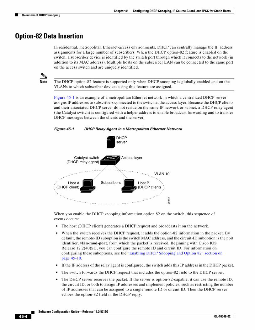
Figure 45-1 is an example of a metropolitan Ethernet network in which a centralized DHCP server assigns IP addresses to subscribers connected to the switch at the access layer. Because the DHCP clients and their associated DHCP server do not reside on the same IP network or subnet, a DHCP relay agent (the Catalyst switch) is configured with a helper address to enable broadcast forwarding and to transfer DHCP messages between the clients and the server.
Figure 45-1 DHCP Relay Agent in a Metropolitan Ethernet Network
When you enable the DHCP snooping information option 82 on the switch, this sequence of events occurs:
• The host (DHCP client) generates a DHCP request and broadcasts it on the network.
• When the switch receives the DHCP request, it adds the option-82 information in the packet. By default, the remote-ID suboption is the switch MAC address, and the circuit-ID suboption is the port identifier, vlan-mod-port, from which the packet is received. Beginning with Cisco IOS Release 12.2(40)SG, you can configure the remote ID and circuit ID. For information on configuring these suboptions, see the “Enabling DHCP Snooping and Option 82” section on page 45-10.
• If the IP address of the relay agent is configured, the switch adds this IP address in the DHCP packet.
• The switch forwards the DHCP request that includes the option-82 field to the DHCP server.
• The DHCP server receives the packet. If the server is option-82-capable, it can use the remote ID, the circuit ID, or both to assign IP addresses and implement policies, such as restricting the number of IP addresses that can be assigned to a single remote ID or circuit ID. Then the DHCP server echoes the option-82 field in the DHCP reply.
Subscribers
Catalyst switch(DHCP relay agent)
Host A(DHCP client)
Access layer
DHCPserver
Host B(DHCP client)
9881
3
VLAN 10
45-4Software Configuration Guide—Release 12.2(53)SG
OL-16048-02

Chapter 45 Configuring DHCP Snooping, IP Source Guard, and IPSG for Static HostsOverview of DHCP Snooping
• The DHCP server unicasts the reply to the switch if the request was relayed to the server by the switch. The switch verifies that it originally inserted the option-82 data by inspecting the remote ID and possibly the circuit ID fields. The switch removes the option-82 field and forwards the packet to the switch port that connects to the DHCP client that sent the DHCP request.
In the default suboption configuration, when the described sequence of events occurs, the values in these fields in Figure 45-2 do not change:
• Circuit-ID suboption fields
– Suboption type
– Length of the suboption type
– Circuit-ID type
– Length of the circuit-ID type
• Remote-ID suboption fields
– Suboption type
– Length of the suboption type
– Remote-ID type
– Length of the remote-ID type
Figure 45-2 shows the packet formats for the remote-ID suboption and the circuit-ID suboption when the default suboption configuration is used. For the circuit-ID suboption, the module number corresponds to the switch module number. The switch uses the packet formats when you globally enable DHCP snooping and enter the ip dhcp snooping information option global configuration command.
Figure 45-2 Suboption Packet Formats
Length Length
CircuitID type
Suboptiontype
Circuit ID Suboption Frame Format
Remote ID Suboption Frame Format
6 bytes
MAC address
1 byte 1 byte 1 byte
Suboptiontype
1 byte
Length Length
RemoteID type
1 byte 1 byte 1 byte1 byte 1163
00
4061
6082
Module Port
1 byte 1 byte2 bytes
VLAN
45-5Software Configuration Guide—Release 12.2(53)SG
OL-16048-02
Chapter 45 Configuring DHCP Snooping, IP Source Guard, and IPSG for Static HostsConfiguring DHCP Snooping
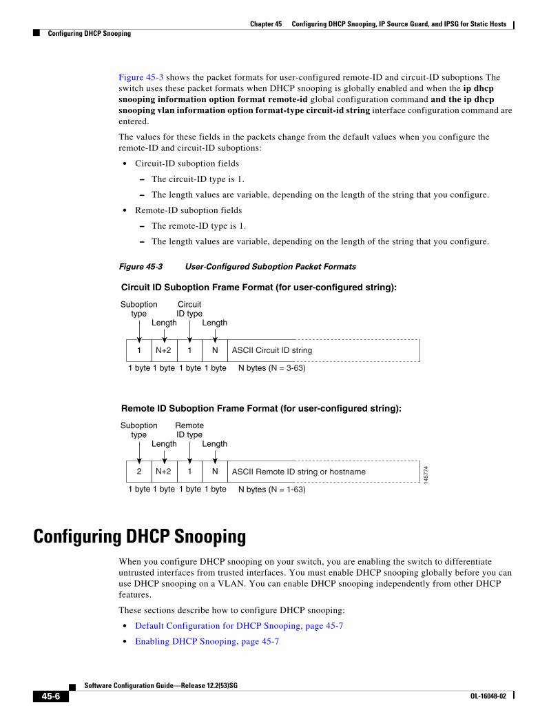
Figure 45-3 shows the packet formats for user-configured remote-ID and circuit-ID suboptions The switch uses these packet formats when DHCP snooping is globally enabled and when the ip dhcp snooping information option format remote-id global configuration command and the ip dhcp snooping vlan information option format-type circuit-id string interface configuration command are entered.
The values for these fields in the packets change from the default values when you configure the remote-ID and circuit-ID suboptions:
• Circuit-ID suboption fields
– The circuit-ID type is 1.
– The length values are variable, depending on the length of the string that you configure.
• Remote-ID suboption fields
– The remote-ID type is 1.
– The length values are variable, depending on the length of the string that you configure.
Figure 45-3 User-Configured Suboption Packet Formats
Configuring DHCP SnoopingWhen you configure DHCP snooping on your switch, you are enabling the switch to differentiate untrusted interfaces from trusted interfaces. You must enable DHCP snooping globally before you can use DHCP snooping on a VLAN. You can enable DHCP snooping independently from other DHCP features.
These sections describe how to configure DHCP snooping:
• Default Configuration for DHCP Snooping, page 45-7
• Enabling DHCP Snooping, page 45-7
Length Length
CircuitID type
Suboptiontype
Circuit ID Suboption Frame Format (for user-configured string):
Remote ID Suboption Frame Format (for user-configured string):
Suboptiontype
Length Length
RemoteID type
1457
74
N1N+2 1
N1N+2 2
ASCII Circuit ID string
1 byte 1 byte 1 byte N bytes (N = 3-63)
ASCII Remote ID string or hostname
N bytes (N = 1-63)
1 byte
1 byte 1 byte 1 byte1 byte
45-6Software Configuration Guide—Release 12.2(53)SG
OL-16048-02
Chapter 45 Configuring DHCP Snooping, IP Source Guard, and IPSG for Static HostsConfiguring DHCP Snooping
• Enabling DHCP Snooping on the Aggregation Switch, page 45-9
• Enabling DHCP Snooping and Option 82, page 45-10
• Enabling DHCP Snooping on Private VLAN, page 45-11
• Configuring DHCP Snooping on Private VLAN, page 45-12
• Configuring DHCP Snooping with an Ethernet Channel Group, page 45-12
• Enabling the DHCP Snooping Database Agent, page 45-12
• Limiting the Rate of Incoming DHCP Packets, page 45-13
• Configuration Examples for the Database Agent, page 45-15
Note For DHCP server configuration information, refer to “Configuring DHCP” in the Cisco IOS IP and IP Routing Configuration Guide at:
http://www.cisco.com/en/US/docs/ios/12_2/ip/configuration/guide/1cfdhcp.html
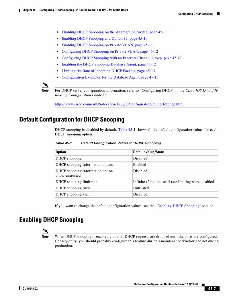
Default Configuration for DHCP SnoopingDHCP snooping is disabled by default. Table 45-1 shows all the default configuration values for each DHCP snooping option.
If you want to change the default configuration values, see the “Enabling DHCP Snooping” section.
Enabling DHCP Snooping
Note When DHCP snooping is enabled globally, DHCP requests are dropped until the ports are configured. Consequently, you should probably configure this feature during a maintenance window and not during production.
Table 45-1 Default Configuration Values for DHCP Snooping
Option Default Value/State
DHCP snooping Disabled
DHCP snooping information option Enabled
DHCP snooping information option allow-untrusted
Disabled
DHCP snooping limit rate Infinite (functions as if rate limiting were disabled)
DHCP snooping trust Untrusted
DHCP snooping vlan Disabled
45-7Software Configuration Guide—Release 12.2(53)SG
OL-16048-02
Chapter 45 Configuring DHCP Snooping, IP Source Guard, and IPSG for Static HostsConfiguring DHCP Snooping
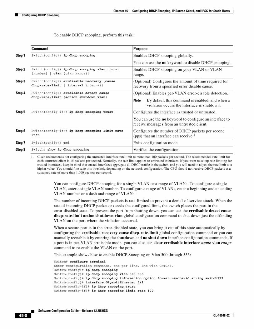
To enable DHCP snooping, perform this task:
You can configure DHCP snooping for a single VLAN or a range of VLANs. To configure a single VLAN, enter a single VLAN number. To configure a range of VLANs, enter a beginning and an ending VLAN number or a dash and range of VLANs.
The number of incoming DHCP packets is rate-limited to prevent a denial-of-service attack. When the rate of incoming DHCP packets exceeds the configured limit, the switch places the port in the error-disabled state. To prevent the port from shutting down, you can use the errdisable detect cause dhcp-rate-limit action shutdown vlan global configuration command to shut down just the offending VLAN on the port where the violation occurred.
When a secure port is in the error-disabled state, you can bring it out of this state automatically by configuring the errdisable recovery cause dhcp-rate-limit global configuration command or you can manually reenable it by entering the shutdown and no shut down interface configuration commands. If a port is in per-VLAN errdisable mode, you can also use clear errdisable interface name vlan range command to re-enable the VLAN on the port.
This example shows how to enable DHCP Snooping on Vlan 500 through 555:
Switch# configure terminalEnter configuration commands, one per line. End with CNTL/Z.Switch(config)# ip dhcp snoopingSwitch(config)# ip dhcp snooping vlan 500 555Switch(config)# ip dhcp snooping information option format remote-id string switch123Switch(config)# interface GigabitEthernet 5/1Switch(config-if)# ip dhcp snooping trustSwitch(config-if)# ip dhcp snooping limit rate 100
Command Purpose
Step 1 Switch(config)# ip dhcp snooping Enables DHCP snooping globally.
You can use the no keyword to disable DHCP snooping.
Step 2 Switch(config)# ip dhcp snooping vlan number [number] | vlan {vlan range}]
Enables DHCP snooping on your VLAN or VLAN range.
Step 3 Switch(config)# errdisable recovery {cause dhcp-rate-limit | interval interval}
(Optional) Configures the amount of time required for recovery from a specified error disable cause.
Step 4 Switch(config)# errdisable detect cause dhcp-rate-limit {action shutdown vlan}
(Optional) Enables per-VLAN error-disable detection.
Note By default this command is enabled, and when a violation occurs the interface is shutdown.
Step 5 Switch(config-if)# ip dhcp snooping trust Configures the interface as trusted or untrusted.
You can use the no keyword to configure an interface to receive messages from an untrusted client.
Step 6 Switch(config-if)# ip dhcp snooping limit rate rate
Configures the number of DHCP packets per second (pps) that an interface can receive.1
1. Cisco recommends not configuring the untrusted interface rate limit to more than 100 packets per second. The recommended rate limit for each untrusted client is 15 packets per second. Normally, the rate limit applies to untrusted interfaces. If you want to set up rate limiting for trusted interfaces, keep in mind that trusted interfaces aggregate all DHCP traffic in the switch, and you will need to adjust the rate limit to a higher value. You should fine tune this threshold depending on the network configuration. The CPU should not receive DHCP packets at a sustained rate of more than 1,000 packets per second.
Step 7 Switch(config)# end Exits configuration mode.
Step 8 Switch# show ip dhcp snooping Verifies the configuration.
45-8Software Configuration Guide—Release 12.2(53)SG
OL-16048-02
Chapter 45 Configuring DHCP Snooping, IP Source Guard, and IPSG for Static HostsConfiguring DHCP Snooping
Switch(config-if)# ip dhcp snooping vlan 555 information option format-type circuit-id string customer-555Switch(config-if)# interface FastEthernet 2/1Switch(config-if)# ip dhcp snooping vlan 555 information option format-type circuit-id string customer-500Switch(config)# endSwitch# show ip dhcp snoopingSwitch DHCP snooping is enabledDHCP snooping is configured on following VLANs: 500,555DHCP snooping is operational on following VLANs: 500,555DHCP snooping is configured on the following L3 Interfaces:
Insertion of option 82 is enabled circuit-id default format: vlan-mod-port remote-id: switch123 (string)Option 82 on untrusted port is not allowed Verification of hwaddr field is enabled DHCP snooping trust/rate is configured on the following Interfaces:
Interface Trusted Rate limit (pps) ------------------------ ------- ---------------- FastEthernet5/1 yes 100 Custom circuit-ids: VLAN 555: customer-555 FastEthernet2/1 no unlimited Custom circuit-ids: VLAN 500: customer-500
Switch#
The following configuration describes the DHCP snooping configuration steps if routing is defined on another Catalyst switch (for example, a Catalyst 6500 series switch):
// Trust the uplink gigabit Ethernet trunk port
interface range GigabitEthernet 1/1 – 2switchport mode trunkswitchport trunk encapsulation dot1qip dhcp snooping trust
!
interface VLAN 14ip address 10.33.234.1 255.255.254.0ip helper-address 10.5.1.2
Note If you are enabling trunking on uplink gigabit interfaces, and the above routing configuration is defined on a Catalyst 6500 series switch, you must configure the “trust” relationship with downstream DHCP Snooping (on a Catalyst 4500 series switch) which adds Option 82. On a Catalyst 6500 series switch, this task is accomplished with ip dhcp relay information trusted VLAN configuration command.
Enabling DHCP Snooping on the Aggregation SwitchTo enable DHCP Snooping on an aggregation switch, configure the interface connecting to a downstream switch as a snooping untrusted port. If the downstream switch (or a device such as a DSLAM in the path between the aggregation switch and the DHCP clients) adds DHCP information option 82 to the DHCP packets, the DHCP packets would be dropped on arriving on a snooping untrusted
45-9Software Configuration Guide—Release 12.2(53)SG
OL-16048-02
Chapter 45 Configuring DHCP Snooping, IP Source Guard, and IPSG for Static HostsConfiguring DHCP Snooping
port. Configuring the ip dhcp snooping information option allow-untrusted global configuration command on the aggregation switch would allow the aggregation switch to accept DHCP requests with option 82 information from any snooping untrusted port.
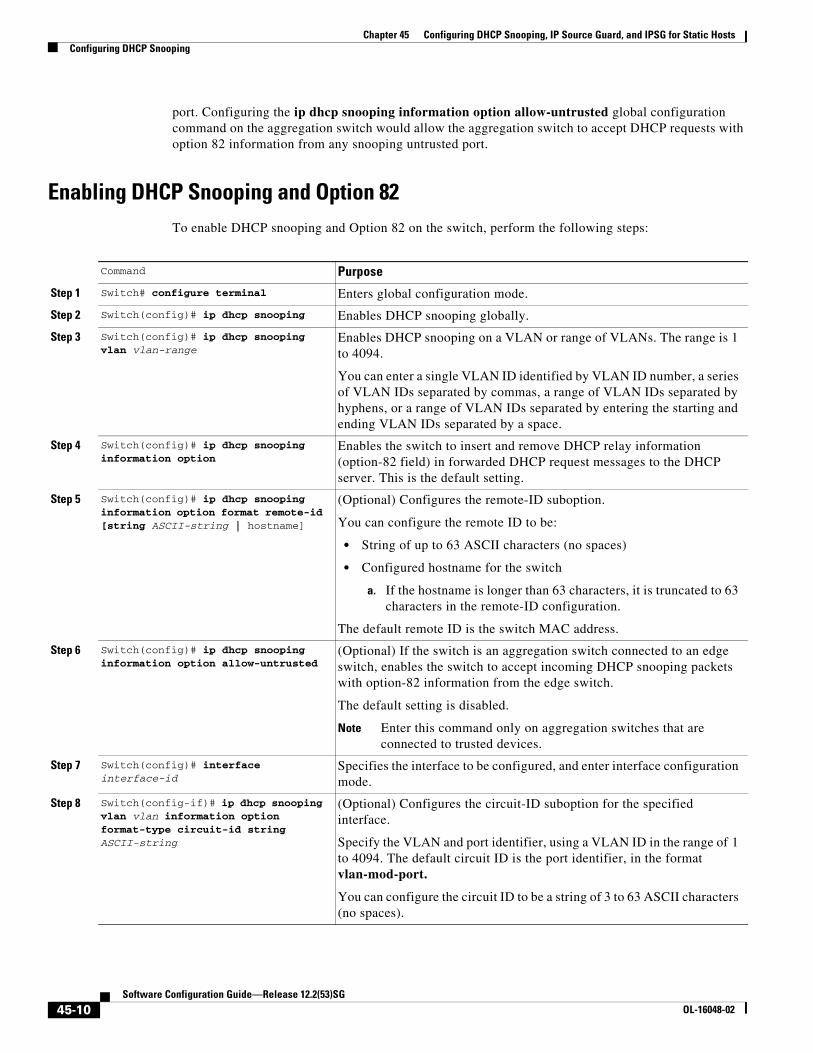
Enabling DHCP Snooping and Option 82To enable DHCP snooping and Option 82 on the switch, perform the following steps:
Command Purpose
Step 1 Switch# configure terminal Enters global configuration mode.
Step 2 Switch(config)# ip dhcp snooping Enables DHCP snooping globally.
Step 3 Switch(config)# ip dhcp snooping vlan vlan-range
Enables DHCP snooping on a VLAN or range of VLANs. The range is 1 to 4094.
You can enter a single VLAN ID identified by VLAN ID number, a series of VLAN IDs separated by commas, a range of VLAN IDs separated by hyphens, or a range of VLAN IDs separated by entering the starting and ending VLAN IDs separated by a space.
Step 4 Switch(config)# ip dhcp snooping information option
Enables the switch to insert and remove DHCP relay information (option-82 field) in forwarded DHCP request messages to the DHCP server. This is the default setting.
Step 5 Switch(config)# ip dhcp snooping information option format remote-id [string ASCII-string | hostname]
(Optional) Configures the remote-ID suboption.
You can configure the remote ID to be:
• String of up to 63 ASCII characters (no spaces)
• Configured hostname for the switch
a. If the hostname is longer than 63 characters, it is truncated to 63 characters in the remote-ID configuration.
The default remote ID is the switch MAC address.
Step 6 Switch(config)# ip dhcp snooping information option allow-untrusted
(Optional) If the switch is an aggregation switch connected to an edge switch, enables the switch to accept incoming DHCP snooping packets with option-82 information from the edge switch.
The default setting is disabled.
Note Enter this command only on aggregation switches that are connected to trusted devices.
Step 7 Switch(config)# interface interface-id
Specifies the interface to be configured, and enter interface configuration mode.
Step 8 Switch(config-if)# ip dhcp snooping vlan vlan information option format-type circuit-id string ASCII-string
(Optional) Configures the circuit-ID suboption for the specified interface.
Specify the VLAN and port identifier, using a VLAN ID in the range of 1 to 4094. The default circuit ID is the port identifier, in the format vlan-mod-port.
You can configure the circuit ID to be a string of 3 to 63 ASCII characters (no spaces).
45-10Software Configuration Guide—Release 12.2(53)SG
OL-16048-02
Chapter 45 Configuring DHCP Snooping, IP Source Guard, and IPSG for Static HostsConfiguring DHCP Snooping
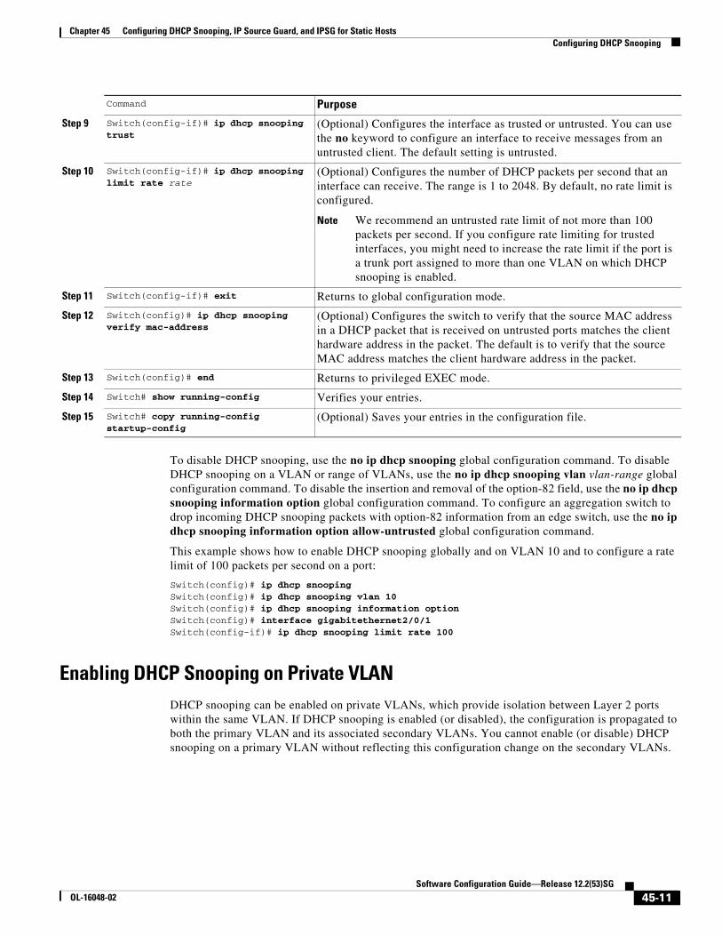
To disable DHCP snooping, use the no ip dhcp snooping global configuration command. To disable DHCP snooping on a VLAN or range of VLANs, use the no ip dhcp snooping vlan vlan-range global configuration command. To disable the insertion and removal of the option-82 field, use the no ip dhcp snooping information option global configuration command. To configure an aggregation switch to drop incoming DHCP snooping packets with option-82 information from an edge switch, use the no ip dhcp snooping information option allow-untrusted global configuration command.
This example shows how to enable DHCP snooping globally and on VLAN 10 and to configure a rate limit of 100 packets per second on a port:
Switch(config)# ip dhcp snoopingSwitch(config)# ip dhcp snooping vlan 10Switch(config)# ip dhcp snooping information optionSwitch(config)# interface gigabitethernet2/0/1Switch(config-if)# ip dhcp snooping limit rate 100
Enabling DHCP Snooping on Private VLAN DHCP snooping can be enabled on private VLANs, which provide isolation between Layer 2 ports within the same VLAN. If DHCP snooping is enabled (or disabled), the configuration is propagated to both the primary VLAN and its associated secondary VLANs. You cannot enable (or disable) DHCP snooping on a primary VLAN without reflecting this configuration change on the secondary VLANs.
Step 9 Switch(config-if)# ip dhcp snooping trust
(Optional) Configures the interface as trusted or untrusted. You can use the no keyword to configure an interface to receive messages from an untrusted client. The default setting is untrusted.
Step 10 Switch(config-if)# ip dhcp snooping limit rate rate
(Optional) Configures the number of DHCP packets per second that an interface can receive. The range is 1 to 2048. By default, no rate limit is configured.
Note We recommend an untrusted rate limit of not more than 100 packets per second. If you configure rate limiting for trusted interfaces, you might need to increase the rate limit if the port is a trunk port assigned to more than one VLAN on which DHCP snooping is enabled.
Step 11 Switch(config-if)# exit Returns to global configuration mode.
Step 12 Switch(config)# ip dhcp snooping verify mac-address
(Optional) Configures the switch to verify that the source MAC address in a DHCP packet that is received on untrusted ports matches the client hardware address in the packet. The default is to verify that the source MAC address matches the client hardware address in the packet.
Step 13 Switch(config)# end Returns to privileged EXEC mode.
Step 14 Switch# show running-config Verifies your entries.
Step 15 Switch# copy running-config startup-config
(Optional) Saves your entries in the configuration file.
Command Purpose
45-11Software Configuration Guide—Release 12.2(53)SG
OL-16048-02
Chapter 45 Configuring DHCP Snooping, IP Source Guard, and IPSG for Static HostsConfiguring DHCP Snooping
Configuring DHCP snooping on a secondary VLAN is still allowed, but it does not take effect if the associated primary VLAN is already configured. If the associated primary VLAN is configured, the effective DHCP snooping mode on the secondary VLAN is derived from the corresponding primary VLAN. Manually configuring DHCP snooping on a secondary VLAN causes the switch to issue this warning message:
DHCP Snooping configuration may not take effect on secondary vlan XXX
The show ip dhcp snooping command displays all VLANs (both primary and secondary) that have DHCP snooping enabled.
Configuring DHCP Snooping on Private VLANDHCP snooping, IPSG, and DAI are Layer 2 based security features that can be enabled and disabled on an individual VLAN, including auxiliary or voice VLAN. This means that you need to enable DHCP snooping on a voice VLAN for a Cisco IP phone to function properly.
Configuring DHCP Snooping with an Ethernet Channel GroupWhen you configure DHCP snooping, you need to configure trunk interfaces that transmit DHCP packets as trusted interfaces by adding ip dhcp snooping trust to the physical interface configuration. However, if DHCP packets will be transmitted over an ethernet channel group, you must configure ip dhcp snooping trust on the logical port-channel interface, for example:
Switch# show run int port-channel50Building configuration...
Current configuration : 150 bytes!interface Port-channel50 switchport switchport trunk native vlan 4092 switchport mode trunk switchport nonegotiate ip dhcp snooping trustend
Switch#
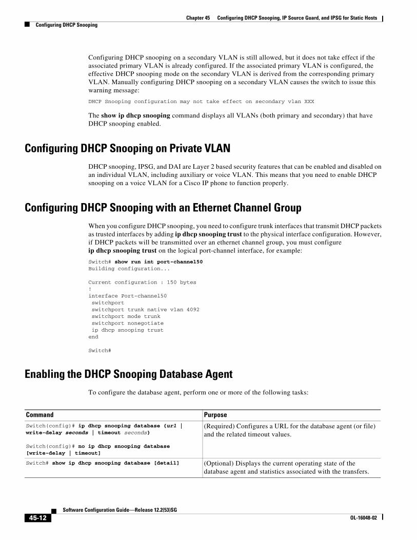
Enabling the DHCP Snooping Database AgentTo configure the database agent, perform one or more of the following tasks:
Command PurposeSwitch(config)# ip dhcp snooping database {url | write-delay seconds | timeout seconds}
Switch(config)# no ip dhcp snooping database [write-delay | timeout]
(Required) Configures a URL for the database agent (or file) and the related timeout values.
Switch# show ip dhcp snooping database [detail] (Optional) Displays the current operating state of the database agent and statistics associated with the transfers.
45-12Software Configuration Guide—Release 12.2(53)SG
OL-16048-02
Chapter 45 Configuring DHCP Snooping, IP Source Guard, and IPSG for Static HostsConfiguring DHCP Snooping
Note Because both NVRAM and bootflash have limited storage capacity, you should use TFTP or network-based files. If you use flash to store the database file, new updates (by the agent) result in the creation of new files (flash fills quickly). Moreover, because of the filesystem used on the flash, a large number of files can cause slow access. When a file is stored in a remote location accessible through TFTP, an RPR/SSO standby supervisor engine can take over the binding list when a switchover occurs.
Note Network-based URLs (such as TFTP and FTP) require that you create an empty file at the configured URL before the switch can write the set of bindings for the first time.
Limiting the Rate of Incoming DHCP PacketsThe switch CPU performs DHCP validation checks; therefore, the number of incoming DHCP packets is rate-limited to prevent a denial-of-service attack.
When the rate of incoming DHCP packets exceeds the configured limit, the switch places the port in the error-disabled state. The port remains in that state until you intervene or you enable error-disable recovery so that ports automatically emerge from this state after a specified timeout period.
Note Unless you explicitly configure a rate limit on an interface, changing the trust state of the interface also changes its rate limit to the default value for that trust state. After you configure the rate limit, the interface retains the rate limit even when its trust state is changed. If you enter the no ip dhcp snooping limit rate interface configuration command, the interface reverts to its default rate limit.
To prevent the port from shutting down, you can use theerrdisable detect cause dhcp-rate-limit action shutdown vlan global configuration command to shut down just the offending VLAN on the port where the violation occurred.
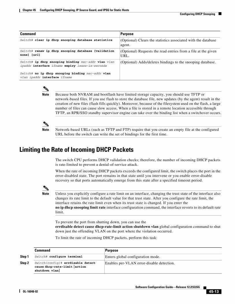
To limit the rate of incoming DHCP packets, perform this task:
Switch# clear ip dhcp snooping database statistics (Optional) Clears the statistics associated with the database agent.
Switch# renew ip dhcp snooping database [validation none] [url]
(Optional) Requests the read entries from a file at the given URL.
Switch# ip dhcp snooping binding mac-addr vlan vlan ipaddr interface ifname expiry lease-in-seconds
Switch# no ip dhcp snooping binding mac-addr vlan vlan ipaddr interface ifname
(Optional) Adds/deletes bindings to the snooping database.
Command Purpose
Command Purpose
Step 1 Switch# configure terminal Enters global configuration mode.
Step 2 Switch(config)# errdisable detect cause dhcp-rate-limit [action shutdown vlan]
Enables per-VLAN error-disable detection.
45-13Software Configuration Guide—Release 12.2(53)SG
OL-16048-02
Chapter 45 Configuring DHCP Snooping, IP Source Guard, and IPSG for Static HostsConfiguring DHCP Snooping
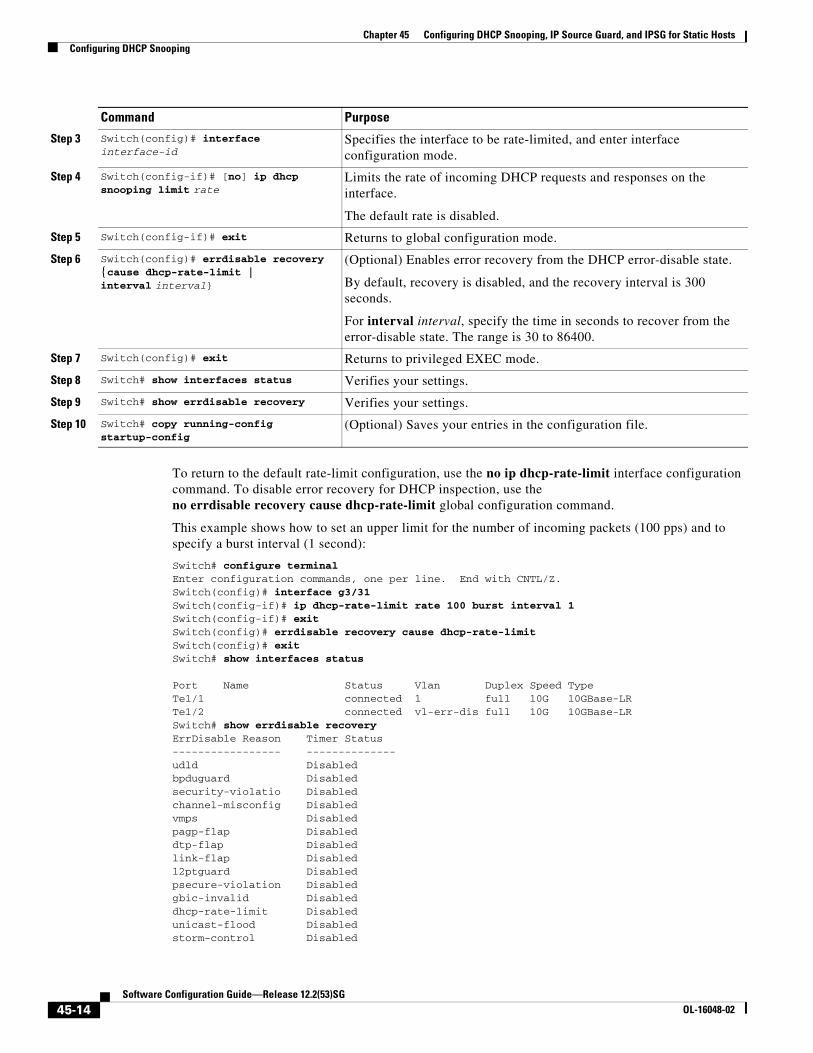
To return to the default rate-limit configuration, use the no ip dhcp-rate-limit interface configuration command. To disable error recovery for DHCP inspection, use the no errdisable recovery cause dhcp-rate-limit global configuration command.
This example shows how to set an upper limit for the number of incoming packets (100 pps) and to specify a burst interval (1 second):
Switch# configure terminalEnter configuration commands, one per line. End with CNTL/Z.Switch(config)# interface g3/31Switch(config-if)# ip dhcp-rate-limit rate 100 burst interval 1Switch(config-if)# exitSwitch(config)# errdisable recovery cause dhcp-rate-limitSwitch(config)# exitSwitch# show interfaces status
Port Name Status Vlan Duplex Speed TypeTe1/1 connected 1 full 10G 10GBase-LRTe1/2 connected vl-err-dis full 10G 10GBase-LRSwitch# show errdisable recoveryErrDisable Reason Timer Status----------------- --------------udld Disabledbpduguard Disabledsecurity-violatio Disabledchannel-misconfig Disabledvmps Disabledpagp-flap Disableddtp-flap Disabledlink-flap Disabledl2ptguard Disabledpsecure-violation Disabledgbic-invalid Disableddhcp-rate-limit Disabledunicast-flood Disabledstorm-control Disabled
Step 3 Switch(config)# interface interface-id
Specifies the interface to be rate-limited, and enter interface configuration mode.
Step 4 Switch(config-if)# [no] ip dhcp snooping limit rate
Limits the rate of incoming DHCP requests and responses on the interface.
The default rate is disabled.
Step 5 Switch(config-if)# exit Returns to global configuration mode.
Step 6 Switch(config)# errdisable recovery {cause dhcp-rate-limit | interval interval}
(Optional) Enables error recovery from the DHCP error-disable state.
By default, recovery is disabled, and the recovery interval is 300 seconds.
For interval interval, specify the time in seconds to recover from the error-disable state. The range is 30 to 86400.
Step 7 Switch(config)# exit Returns to privileged EXEC mode.
Step 8 Switch# show interfaces status Verifies your settings.
Step 9 Switch# show errdisable recovery Verifies your settings.
Step 10 Switch# copy running-config startup-config
(Optional) Saves your entries in the configuration file.
Command Purpose
45-14Software Configuration Guide—Release 12.2(53)SG
OL-16048-02
Chapter 45 Configuring DHCP Snooping, IP Source Guard, and IPSG for Static HostsConfiguring DHCP Snooping
arp-inspection Enabled
Timer interval: 300 seconds
Interfaces that will be enabled at the next timeout:
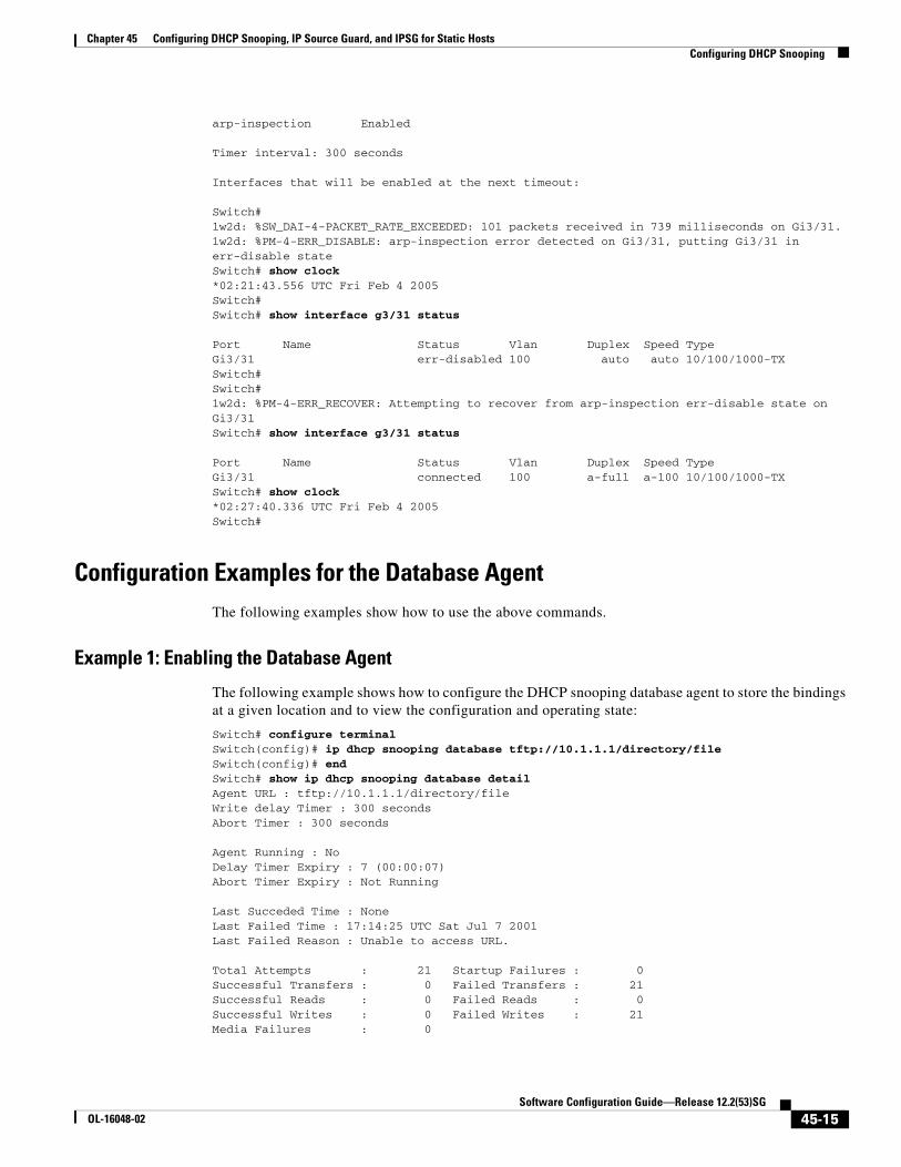
Switch#1w2d: %SW_DAI-4-PACKET_RATE_EXCEEDED: 101 packets received in 739 milliseconds on Gi3/31.1w2d: %PM-4-ERR_DISABLE: arp-inspection error detected on Gi3/31, putting Gi3/31 in err-disable stateSwitch# show clock*02:21:43.556 UTC Fri Feb 4 2005Switch#Switch# show interface g3/31 status
Port Name Status Vlan Duplex Speed TypeGi3/31 err-disabled 100 auto auto 10/100/1000-TXSwitch#Switch#1w2d: %PM-4-ERR_RECOVER: Attempting to recover from arp-inspection err-disable state on Gi3/31Switch# show interface g3/31 status
Port Name Status Vlan Duplex Speed TypeGi3/31 connected 100 a-full a-100 10/100/1000-TXSwitch# show clock*02:27:40.336 UTC Fri Feb 4 2005Switch#
Configuration Examples for the Database AgentThe following examples show how to use the above commands.
Example 1: Enabling the Database Agent
The following example shows how to configure the DHCP snooping database agent to store the bindings at a given location and to view the configuration and operating state:
Switch# configure terminalSwitch(config)# ip dhcp snooping database tftp://10.1.1.1/directory/fileSwitch(config)# endSwitch# show ip dhcp snooping database detailAgent URL : tftp://10.1.1.1/directory/fileWrite delay Timer : 300 secondsAbort Timer : 300 seconds
Agent Running : NoDelay Timer Expiry : 7 (00:00:07)Abort Timer Expiry : Not Running
Last Succeded Time : NoneLast Failed Time : 17:14:25 UTC Sat Jul 7 2001Last Failed Reason : Unable to access URL.
Total Attempts : 21 Startup Failures : 0Successful Transfers : 0 Failed Transfers : 21Successful Reads : 0 Failed Reads : 0Successful Writes : 0 Failed Writes : 21Media Failures : 0
45-15Software Configuration Guide—Release 12.2(53)SG
OL-16048-02
Chapter 45 Configuring DHCP Snooping, IP Source Guard, and IPSG for Static HostsConfiguring DHCP Snooping
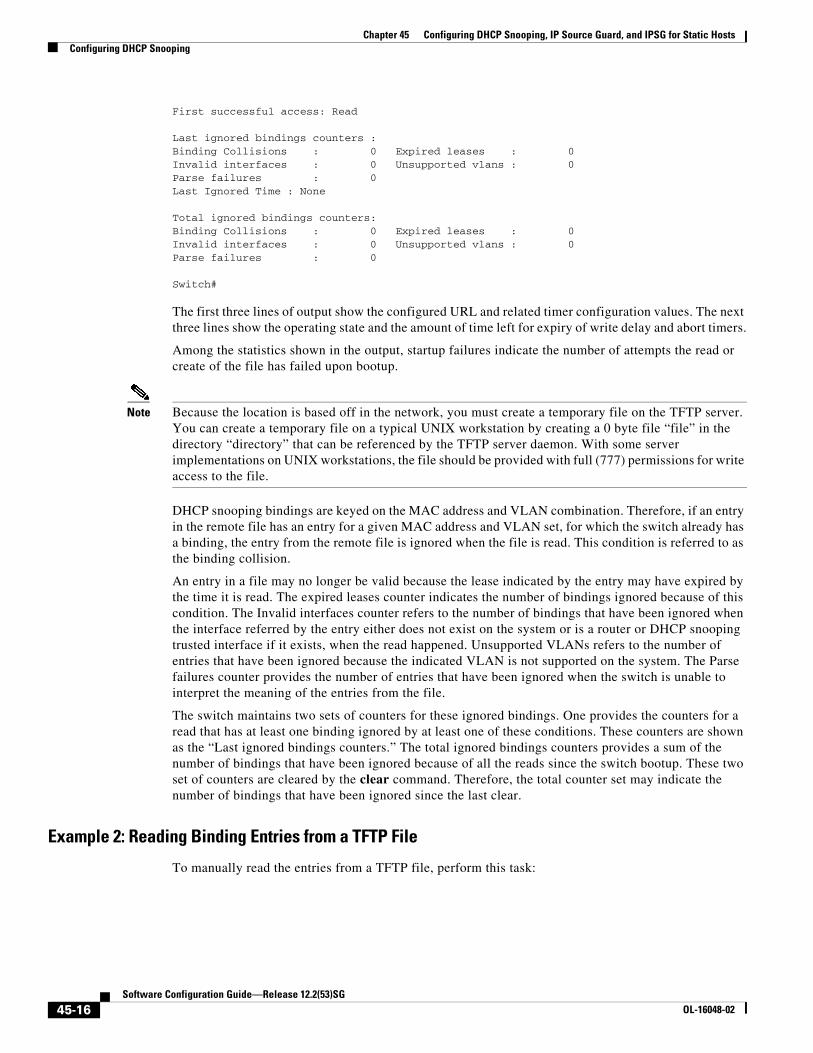
First successful access: Read
Last ignored bindings counters :Binding Collisions : 0 Expired leases : 0Invalid interfaces : 0 Unsupported vlans : 0Parse failures : 0Last Ignored Time : None
Total ignored bindings counters:Binding Collisions : 0 Expired leases : 0Invalid interfaces : 0 Unsupported vlans : 0Parse failures : 0
Switch#
The first three lines of output show the configured URL and related timer configuration values. The next three lines show the operating state and the amount of time left for expiry of write delay and abort timers.
Among the statistics shown in the output, startup failures indicate the number of attempts the read or create of the file has failed upon bootup.
Note Because the location is based off in the network, you must create a temporary file on the TFTP server. You can create a temporary file on a typical UNIX workstation by creating a 0 byte file “file” in the directory “directory” that can be referenced by the TFTP server daemon. With some server implementations on UNIX workstations, the file should be provided with full (777) permissions for write access to the file.
DHCP snooping bindings are keyed on the MAC address and VLAN combination. Therefore, if an entry in the remote file has an entry for a given MAC address and VLAN set, for which the switch already has a binding, the entry from the remote file is ignored when the file is read. This condition is referred to as the binding collision.
An entry in a file may no longer be valid because the lease indicated by the entry may have expired by the time it is read. The expired leases counter indicates the number of bindings ignored because of this condition. The Invalid interfaces counter refers to the number of bindings that have been ignored when the interface referred by the entry either does not exist on the system or is a router or DHCP snooping trusted interface if it exists, when the read happened. Unsupported VLANs refers to the number of entries that have been ignored because the indicated VLAN is not supported on the system. The Parse failures counter provides the number of entries that have been ignored when the switch is unable to interpret the meaning of the entries from the file.
The switch maintains two sets of counters for these ignored bindings. One provides the counters for a read that has at least one binding ignored by at least one of these conditions. These counters are shown as the “Last ignored bindings counters.” The total ignored bindings counters provides a sum of the number of bindings that have been ignored because of all the reads since the switch bootup. These two set of counters are cleared by the clear command. Therefore, the total counter set may indicate the number of bindings that have been ignored since the last clear.
Example 2: Reading Binding Entries from a TFTP File
To manually read the entries from a TFTP file, perform this task:
45-16Software Configuration Guide—Release 12.2(53)SG
OL-16048-02
Chapter 45 Configuring DHCP Snooping, IP Source Guard, and IPSG for Static HostsConfiguring DHCP Snooping
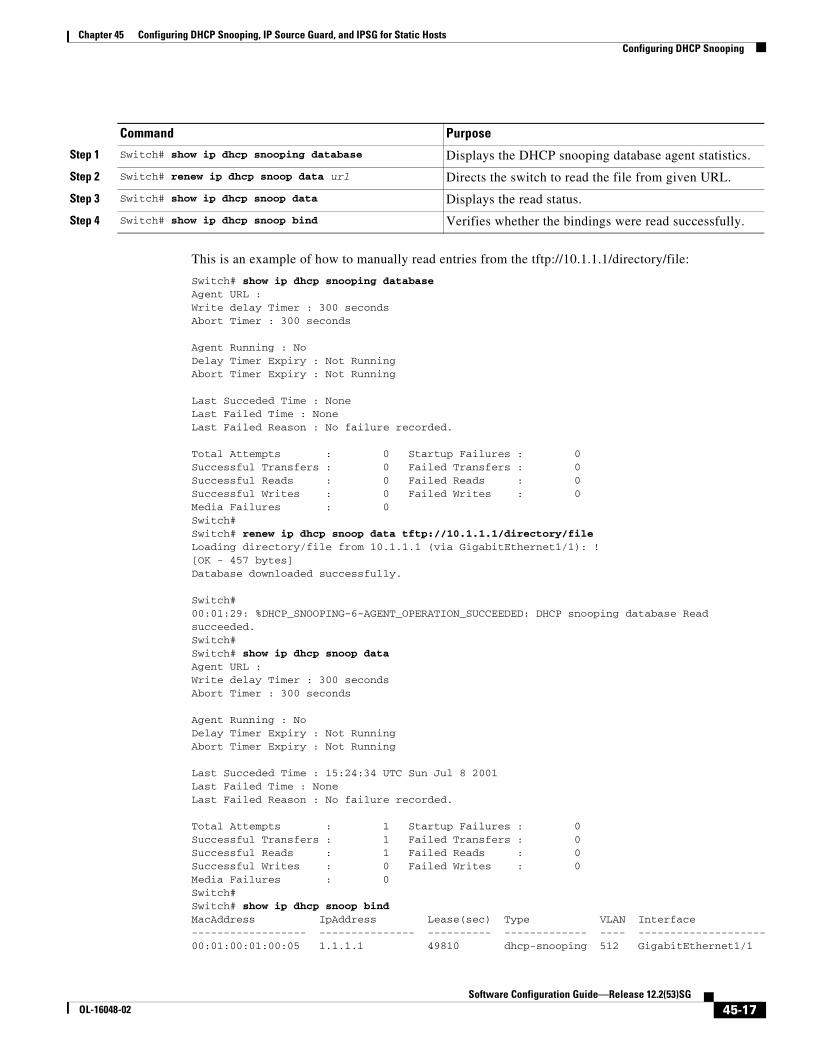
This is an example of how to manually read entries from the tftp://10.1.1.1/directory/file:
Switch# show ip dhcp snooping databaseAgent URL : Write delay Timer : 300 secondsAbort Timer : 300 seconds
Agent Running : NoDelay Timer Expiry : Not RunningAbort Timer Expiry : Not Running
Last Succeded Time : NoneLast Failed Time : NoneLast Failed Reason : No failure recorded.
Total Attempts : 0 Startup Failures : 0Successful Transfers : 0 Failed Transfers : 0Successful Reads : 0 Failed Reads : 0Successful Writes : 0 Failed Writes : 0Media Failures : 0Switch#Switch# renew ip dhcp snoop data tftp://10.1.1.1/directory/fileLoading directory/file from 10.1.1.1 (via GigabitEthernet1/1): ![OK - 457 bytes]Database downloaded successfully.
Switch#00:01:29: %DHCP_SNOOPING-6-AGENT_OPERATION_SUCCEEDED: DHCP snooping database Read succeeded.Switch#Switch# show ip dhcp snoop dataAgent URL : Write delay Timer : 300 secondsAbort Timer : 300 seconds
Agent Running : NoDelay Timer Expiry : Not RunningAbort Timer Expiry : Not Running
Last Succeded Time : 15:24:34 UTC Sun Jul 8 2001Last Failed Time : NoneLast Failed Reason : No failure recorded.
Total Attempts : 1 Startup Failures : 0Successful Transfers : 1 Failed Transfers : 0Successful Reads : 1 Failed Reads : 0Successful Writes : 0 Failed Writes : 0Media Failures : 0Switch#Switch# show ip dhcp snoop bindMacAddress IpAddress Lease(sec) Type VLAN Interface------------------ --------------- ---------- ------------- ---- --------------------00:01:00:01:00:05 1.1.1.1 49810 dhcp-snooping 512 GigabitEthernet1/1
Command Purpose
Step 1 Switch# show ip dhcp snooping database Displays the DHCP snooping database agent statistics.
Step 2 Switch# renew ip dhcp snoop data url Directs the switch to read the file from given URL.
Step 3 Switch# show ip dhcp snoop data Displays the read status.
Step 4 Switch# show ip dhcp snoop bind Verifies whether the bindings were read successfully.
45-17Software Configuration Guide—Release 12.2(53)SG
OL-16048-02
Chapter 45 Configuring DHCP Snooping, IP Source Guard, and IPSG for Static HostsDisplaying DHCP Snooping Information
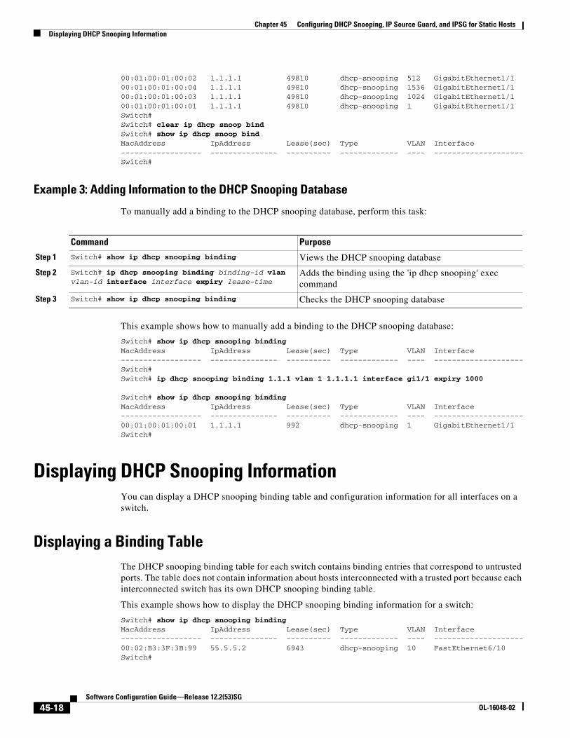
00:01:00:01:00:02 1.1.1.1 49810 dhcp-snooping 512 GigabitEthernet1/100:01:00:01:00:04 1.1.1.1 49810 dhcp-snooping 1536 GigabitEthernet1/100:01:00:01:00:03 1.1.1.1 49810 dhcp-snooping 1024 GigabitEthernet1/100:01:00:01:00:01 1.1.1.1 49810 dhcp-snooping 1 GigabitEthernet1/1Switch#Switch# clear ip dhcp snoop bindSwitch# show ip dhcp snoop bindMacAddress IpAddress Lease(sec) Type VLAN Interface------------------ --------------- ---------- ------------- ---- --------------------Switch#
Example 3: Adding Information to the DHCP Snooping Database
To manually add a binding to the DHCP snooping database, perform this task:
This example shows how to manually add a binding to the DHCP snooping database:
Switch# show ip dhcp snooping bindingMacAddress IpAddress Lease(sec) Type VLAN Interface------------------ --------------- ---------- ------------- ---- --------------------Switch#Switch# ip dhcp snooping binding 1.1.1 vlan 1 1.1.1.1 interface gi1/1 expiry 1000
Switch# show ip dhcp snooping bindingMacAddress IpAddress Lease(sec) Type VLAN Interface------------------ --------------- ---------- ------------- ---- --------------------00:01:00:01:00:01 1.1.1.1 992 dhcp-snooping 1 GigabitEthernet1/1Switch#
Displaying DHCP Snooping InformationYou can display a DHCP snooping binding table and configuration information for all interfaces on a switch.
Displaying a Binding TableThe DHCP snooping binding table for each switch contains binding entries that correspond to untrusted ports. The table does not contain information about hosts interconnected with a trusted port because each interconnected switch has its own DHCP snooping binding table.
This example shows how to display the DHCP snooping binding information for a switch:
Switch# show ip dhcp snooping bindingMacAddress IpAddress Lease(sec) Type VLAN Interface------------------ --------------- ---------- ------------- ---- --------------------00:02:B3:3F:3B:99 55.5.5.2 6943 dhcp-snooping 10 FastEthernet6/10Switch#
Command Purpose
Step 1 Switch# show ip dhcp snooping binding Views the DHCP snooping database
Step 2 Switch# ip dhcp snooping binding binding-id vlan vlan-id interface interface expiry lease-time
Adds the binding using the 'ip dhcp snooping' exec command
Step 3 Switch# show ip dhcp snooping binding Checks the DHCP snooping database
45-18Software Configuration Guide—Release 12.2(53)SG
OL-16048-02
Chapter 45 Configuring DHCP Snooping, IP Source Guard, and IPSG for Static HostsOverview of IP Source Guard
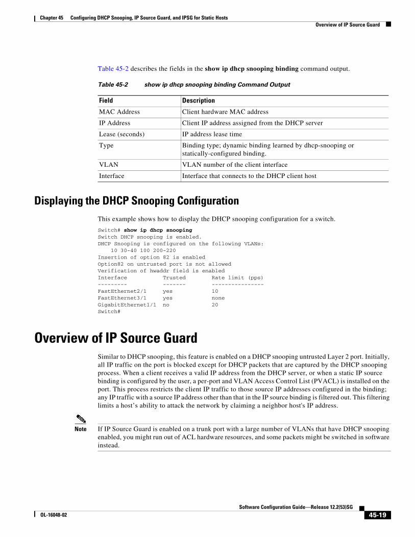
Table 45-2 describes the fields in the show ip dhcp snooping binding command output.
Displaying the DHCP Snooping ConfigurationThis example shows how to display the DHCP snooping configuration for a switch.
Switch# show ip dhcp snoopingSwitch DHCP snooping is enabled.DHCP Snooping is configured on the following VLANs:
10 30-40 100 200-220Insertion of option 82 is enabled Option82 on untrusted port is not allowedVerification of hwaddr field is enabledInterface Trusted Rate limit (pps)--------- ------- ---------------- FastEthernet2/1 yes 10FastEthernet3/1 yes noneGigabitEthernet1/1 no 20Switch#
Overview of IP Source GuardSimilar to DHCP snooping, this feature is enabled on a DHCP snooping untrusted Layer 2 port. Initially, all IP traffic on the port is blocked except for DHCP packets that are captured by the DHCP snooping process. When a client receives a valid IP address from the DHCP server, or when a static IP source binding is configured by the user, a per-port and VLAN Access Control List (PVACL) is installed on the port. This process restricts the client IP traffic to those source IP addresses configured in the binding; any IP traffic with a source IP address other than that in the IP source binding is filtered out. This filtering limits a host’s ability to attack the network by claiming a neighbor host's IP address.
Note If IP Source Guard is enabled on a trunk port with a large number of VLANs that have DHCP snooping enabled, you might run out of ACL hardware resources, and some packets might be switched in software instead.
Table 45-2 show ip dhcp snooping binding Command Output
Field Description
MAC Address Client hardware MAC address
IP Address Client IP address assigned from the DHCP server
Lease (seconds) IP address lease time
Type Binding type; dynamic binding learned by dhcp-snooping or statically-configured binding.
VLAN VLAN number of the client interface
Interface Interface that connects to the DHCP client host
45-19Software Configuration Guide—Release 12.2(53)SG
OL-16048-02
Chapter 45 Configuring DHCP Snooping, IP Source Guard, and IPSG for Static HostsConfiguring IP Source Guard
Note When IP Source Guard is enabled, you might want to designate an alternative scheme for ACL hardware programming. For more information, see the “TCAM Programming and ACLs” section in the “Configuring Network Security with ACLs” chapter.
Note When an interface is in down state, TCAMs are not consumed for RACLs, but are for PACLs.
IP Source Guard supports the Layer 2 port only, including both access and trunk. For each untrusted Layer 2 port, there are two levels of IP traffic security filtering:
• Source IP address filter
IP traffic is filtered based on its source IP address. Only IP traffic with a source IP address that matches the IP source binding entry is permitted.
An IP source address filter is changed when a new IP source entry binding is created or deleted on the port. The port PVACL is recalculated and reapplied in the hardware to reflect the IP source binding change. By default, if the IP filter is enabled without any IP source binding on the port, a default PVACL that denies all IP traffic is installed on the port. Similarly, when the IP filter is disabled, any IP source filter PVACL is removed from the interface.
• Source IP and MAC address filter
IP traffic is filtered based on its source IP address as well as its MAC address; only IP traffic with source IP and MAC addresses matching the IP source binding entry are permitted.
Note When IP source guard is enabled in IP and MAC filtering mode, the DHCP snooping option 82 must be enabled to ensure that the DHCP protocol works properly. Without option 82 data, the switch cannot locate the client host port to forward the DHCP server reply. Instead, the DHCP server reply is dropped, and the client cannot obtain an IP address.
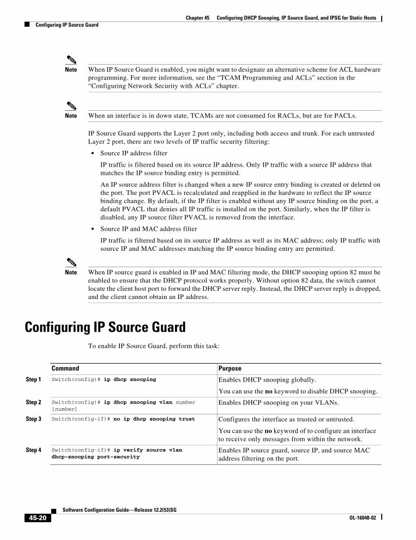
Configuring IP Source GuardTo enable IP Source Guard, perform this task:
Command Purpose
Step 1 Switch(config)# ip dhcp snooping Enables DHCP snooping globally.
You can use the no keyword to disable DHCP snooping.
Step 2 Switch(config)# ip dhcp snooping vlan number [number]
Enables DHCP snooping on your VLANs.
Step 3 Switch(config-if)# no ip dhcp snooping trust Configures the interface as trusted or untrusted.
You can use the no keyword of to configure an interface to receive only messages from within the network.
Step 4 Switch(config-if)# ip verify source vlan dhcp-snooping port-security
Enables IP source guard, source IP, and source MAC address filtering on the port.
45-20Software Configuration Guide—Release 12.2(53)SG
OL-16048-02
Chapter 45 Configuring DHCP Snooping, IP Source Guard, and IPSG for Static HostsConfiguring IP Source Guard
If you want to stop IP Source Guard with Static Hosts on an interface, use the following commands in interface configuration submode:
Switch(config-if)# no ip verify sourceSwitch(config-if)# no ip device tracking max
If the ip device tracking command is used in the interface configuration submode, it will be interpreted and run in the global configuration mode, disabling IP device tracking globally. For all interfaces configured with the ip verify source tracking [port-security] command, disabling IP device tracking globally causes the IP Source Guard with Static Hosts feature to deny all IP traffic from those interfaces.
Note The static IP source binding can only be configured on switch port. If you issue theip source binding vlan interface command on a Layer 3 port, you receive this error message: Static IP source binding can only be configured on switch port.
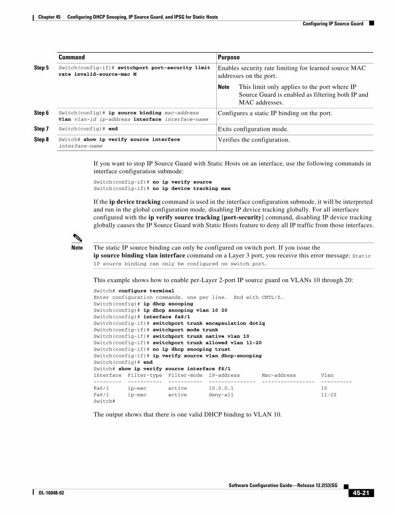
This example shows how to enable per-Layer 2-port IP source guard on VLANs 10 through 20:
Switch# configure terminalEnter configuration commands, one per line. End with CNTL/Z.Switch(config)# ip dhcp snoopingSwitch(config)# ip dhcp snooping vlan 10 20Switch(config)# interface fa6/1Switch(config-if)# switchport trunk encapsulation dot1qSwitch(config-if)# switchport mode trunkSwitch(config-if)# switchport trunk native vlan 10Switch(config-if)# switchport trunk allowed vlan 11-20Switch(config-if)# no ip dhcp snooping trustSwitch(config-if)# ip verify source vlan dhcp-snoopingSwitch(config)# endSwitch# show ip verify source interface f6/1Interface Filter-type Filter-mode IP-address Mac-address Vlan--------- ----------- ----------- --------------- ----------------- ----------Fa6/1 ip-mac active 10.0.0.1 10 Fa6/1 ip-mac active deny-all 11-20 Switch#
The output shows that there is one valid DHCP binding to VLAN 10.
Step 5 Switch(config-if)# switchport port-security limit rate invalid-source-mac N
Enables security rate limiting for learned source MAC addresses on the port.
Note This limit only applies to the port where IP Source Guard is enabled as filtering both IP and MAC addresses.
Step 6 Switch(config)# ip source binding mac-address Vlan vlan-id ip-address interface interface-name
Configures a static IP binding on the port.
Step 7 Switch(config)# end Exits configuration mode.
Step 8 Switch# show ip verify source interface interface-name
Verifies the configuration.
Command Purpose
45-21Software Configuration Guide—Release 12.2(53)SG
OL-16048-02
Chapter 45 Configuring DHCP Snooping, IP Source Guard, and IPSG for Static HostsDisplaying IP Source Guard Information
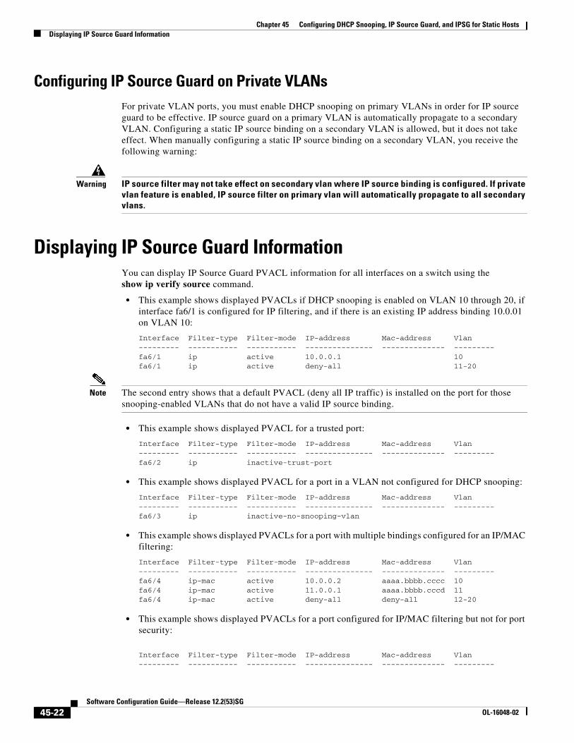
Configuring IP Source Guard on Private VLANsFor private VLAN ports, you must enable DHCP snooping on primary VLANs in order for IP source guard to be effective. IP source guard on a primary VLAN is automatically propagate to a secondary VLAN. Configuring a static IP source binding on a secondary VLAN is allowed, but it does not take effect. When manually configuring a static IP source binding on a secondary VLAN, you receive the following warning:
Warning IP source filter may not take effect on secondary vlan where IP source binding is configured. If private vlan feature is enabled, IP source filter on primary vlan will automatically propagate to all secondary vlans.
Displaying IP Source Guard InformationYou can display IP Source Guard PVACL information for all interfaces on a switch using theshow ip verify source command.
• This example shows displayed PVACLs if DHCP snooping is enabled on VLAN 10 through 20, if interface fa6/1 is configured for IP filtering, and if there is an existing IP address binding 10.0.01 on VLAN 10:
Interface Filter-type Filter-mode IP-address Mac-address Vlan--------- ----------- ----------- --------------- -------------- ---------fa6/1 ip active 10.0.0.1 10fa6/1 ip active deny-all 11-20
Note The second entry shows that a default PVACL (deny all IP traffic) is installed on the port for those snooping-enabled VLANs that do not have a valid IP source binding.
• This example shows displayed PVACL for a trusted port:
Interface Filter-type Filter-mode IP-address Mac-address Vlan--------- ----------- ----------- --------------- -------------- ---------fa6/2 ip inactive-trust-port
• This example shows displayed PVACL for a port in a VLAN not configured for DHCP snooping:
Interface Filter-type Filter-mode IP-address Mac-address Vlan--------- ----------- ----------- --------------- -------------- ---------fa6/3 ip inactive-no-snooping-vlan
• This example shows displayed PVACLs for a port with multiple bindings configured for an IP/MAC filtering:
Interface Filter-type Filter-mode IP-address Mac-address Vlan--------- ----------- ----------- --------------- -------------- ---------fa6/4 ip-mac active 10.0.0.2 aaaa.bbbb.cccc 10fa6/4 ip-mac active 11.0.0.1 aaaa.bbbb.cccd 11fa6/4 ip-mac active deny-all deny-all 12-20
• This example shows displayed PVACLs for a port configured for IP/MAC filtering but not for port security:
Interface Filter-type Filter-mode IP-address Mac-address Vlan--------- ----------- ----------- --------------- -------------- ---------
45-22Software Configuration Guide—Release 12.2(53)SG
OL-16048-02

Chapter 45 Configuring DHCP Snooping, IP Source Guard, and IPSG for Static HostsDisplaying IP Source Binding Information
fa6/5 ip-mac active 10.0.0.3 permit-all 10fa6/5 ip-mac active deny-all permit-all 11-20
Note The MAC filter shows permit-all because port security is not enabled, so the MAC filter cannot apply to the port/VLAN and is effectively disabled. Always enable port security first.
• This example shows displayed error message when issuing the show ip verify source command on a port that does not have an IP source filter mode configured:
IP Source Guard is not configured on the interface fa6/6.
You can also use the show ip verify source command to display all interfaces on the switch that have IP source guard enabled:
Interface Filter-type Filter-mode IP-address Mac-address Vlan--------- ----------- ----------- --------------- -------------- ---------fa6/1 ip active 10.0.0.1 10fa6/1 ip active deny-all 11-20fa6/2 ip inactive-trust-portfa6/3 ip inactive-no-snooping-vlanfa6/4 ip-mac active 10.0.0.2 aaaa.bbbb.cccc 10fa6/4 ip-mac active 11.0.0.1 aaaa.bbbb.cccd 11fa6/4 ip-mac active deny-all deny-all 12-20fa6/5 ip-mac active 10.0.0.3 permit-all 10fa6/5 ip-mac active deny-all permit-all 11-20
Displaying IP Source Binding InformationYou can display all IP source bindings configured on all interfaces on a switch using the show ip source binding command.
Switch# show ip source bindingMacAddress IpAddress Lease(sec) Type VLAN Interface------------------ --------------- ---------- ------------- ---- --------------------00:02:B3:3F:3B:99 55.5.5.2 6522 dhcp-snooping 10 FastEthernet6/1000:00:00:0A:00:0B 11.0.0.1 infinite static 10 FastEthernet6/10Switch#
Table 45-3 describes the fields in the show ip source binding command output.
Table 45-3 show ip source binding Command Output
Field Description
MAC Address Client hardware MAC address
IP Address Client IP address assigned from the DHCP server
Lease (seconds) IP address lease time
Type Binding type; static bindings configured from CLI to dynamic binding learned from DHCP Snooping
VLAN VLAN number of the client interface
Interface Interface that connects to the DHCP client host
45-23Software Configuration Guide—Release 12.2(53)SG
OL-16048-02
Chapter 45 Configuring DHCP Snooping, IP Source Guard, and IPSG for Static HostsConfiguring IP Source Guard for Static Hosts
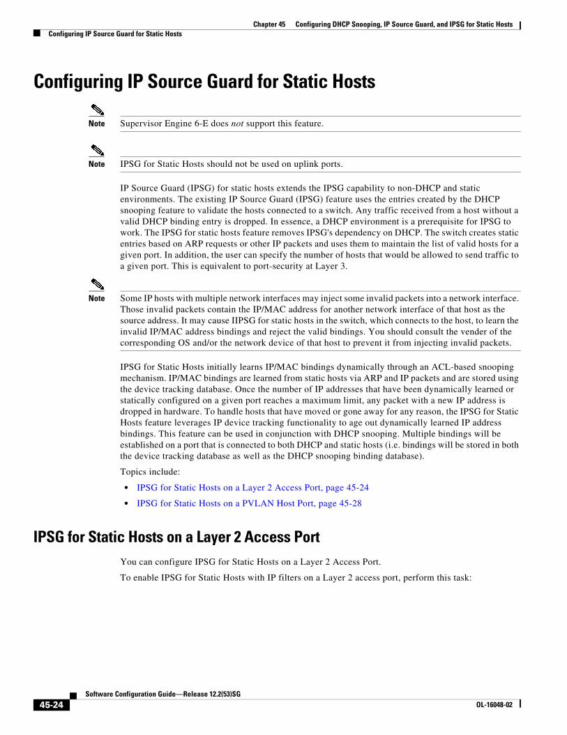
Configuring IP Source Guard for Static Hosts
Note Supervisor Engine 6-E does not support this feature.
Note IPSG for Static Hosts should not be used on uplink ports.
IP Source Guard (IPSG) for static hosts extends the IPSG capability to non-DHCP and static environments. The existing IP Source Guard (IPSG) feature uses the entries created by the DHCP snooping feature to validate the hosts connected to a switch. Any traffic received from a host without a valid DHCP binding entry is dropped. In essence, a DHCP environment is a prerequisite for IPSG to work. The IPSG for static hosts feature removes IPSG's dependency on DHCP. The switch creates static entries based on ARP requests or other IP packets and uses them to maintain the list of valid hosts for a given port. In addition, the user can specify the number of hosts that would be allowed to send traffic to a given port. This is equivalent to port-security at Layer 3.
Note Some IP hosts with multiple network interfaces may inject some invalid packets into a network interface. Those invalid packets contain the IP/MAC address for another network interface of that host as the source address. It may cause IIPSG for static hosts in the switch, which connects to the host, to learn the invalid IP/MAC address bindings and reject the valid bindings. You should consult the vender of the corresponding OS and/or the network device of that host to prevent it from injecting invalid packets.
IPSG for Static Hosts initially learns IP/MAC bindings dynamically through an ACL-based snooping mechanism. IP/MAC bindings are learned from static hosts via ARP and IP packets and are stored using the device tracking database. Once the number of IP addresses that have been dynamically learned or statically configured on a given port reaches a maximum limit, any packet with a new IP address is dropped in hardware. To handle hosts that have moved or gone away for any reason, the IPSG for Static Hosts feature leverages IP device tracking functionality to age out dynamically learned IP address bindings. This feature can be used in conjunction with DHCP snooping. Multiple bindings will be established on a port that is connected to both DHCP and static hosts (i.e. bindings will be stored in both the device tracking database as well as the DHCP snooping binding database).
Topics include:
• IPSG for Static Hosts on a Layer 2 Access Port, page 45-24
• IPSG for Static Hosts on a PVLAN Host Port, page 45-28
IPSG for Static Hosts on a Layer 2 Access PortYou can configure IPSG for Static Hosts on a Layer 2 Access Port.
To enable IPSG for Static Hosts with IP filters on a Layer 2 access port, perform this task:
45-24Software Configuration Guide—Release 12.2(53)SG
OL-16048-02

Chapter 45 Configuring DHCP Snooping, IP Source Guard, and IPSG for Static HostsConfiguring IP Source Guard for Static Hosts
To stop IPSG with Static Hosts on an interface, use the following commands in interface configuration submode:
Switch(config-if)# no ip verify sourceSwitch(config-if)# no ip device tracking max"
To enable IPSG with Static Hosts on a port, issue the following commands:
Switch(config)# ip device tracking ****enable IP device tracking globallySwitch(config)# ip device tracking max <n> ****set an IP device tracking maximum on intSwitch(config-if)# ip verify source tracking [port-security] ****activate IPSG on the port
Caution If you only configure the ip verify source tracking [port-security] interface configuration command on a port without enabling IP device tracking globally or setting an IP device tracking maximum on that interface, IPSG with Static Hosts will reject all the IP traffic from that interface.
Command Purpose
Step 1 Switch(config)# ip device tracking Turns on the IP host table.
Step 2 Switch(config)# ip device tracking [probe {delay interval}]
(Optional) Configures the optional probe delay parameter for the IP device tracking table:
• interval—Number of seconds that the switch delays sending an ARP probe, triggered by link-up and ARP probe generation by the tracked device. The range is 1 to 120 seconds. The default is 0 seconds.
Step 3 Switch(config)# interface fastEthernet <a/b> Enters IP configuration mode.
Step 4 Switch(config-if)# switchport mode access Configures a port as access.
Step 5 Switch(config-if)# switchport access vlan <n> Configures the VLAN for this port.
Step 6 Switch(config-if)# ip device tracking maximum <n> Establishes a maximum limit for the bindings on this port.
Upper bound for the maximum is 10.
Step 7 Switch(config-if)# switchport port-security (Optional) Activates Port Security for this port.
Step 8 Switch(config-if)# switchport port-security maximum <n>
(Optional) Establishes a maximum number of MAC addresses for this port.
Step 9 Switch(config-if)# ip verify source tracking [port-security]
Activates IPSG for Static Hosts on this port.
Step 10 Switch(config-if)# end Exits configuration interface mode.
Step 11 Switch# show ip verify source interface-name Verifies the configuration.
Step 12 Switch# show ip device track all[active | inactive] count
Verifies the configuration by displaying the IP-to-MAC binding for a given host on the switch interface.
• all active - displays only the active IP/MAC binding entries
• all inactive - displays only the inactive IP/MAC binding entries
• all - displays the active and inactive IP/MAC binding entries
45-25Software Configuration Guide—Release 12.2(53)SG
OL-16048-02
Chapter 45 Configuring DHCP Snooping, IP Source Guard, and IPSG for Static HostsConfiguring IP Source Guard for Static Hosts
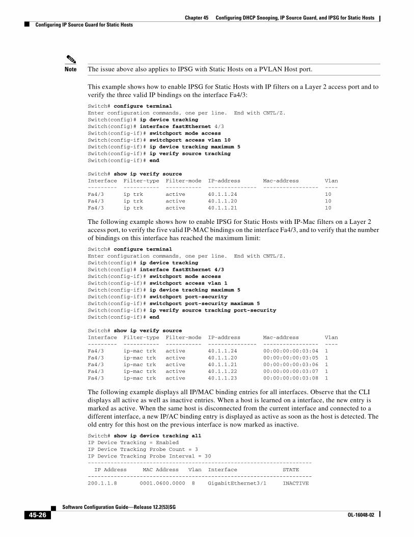
Note The issue above also applies to IPSG with Static Hosts on a PVLAN Host port.
This example shows how to enable IPSG for Static Hosts with IP filters on a Layer 2 access port and to verify the three valid IP bindings on the interface Fa4/3:
Switch# configure terminal Enter configuration commands, one per line. End with CNTL/Z.Switch(config)# ip device trackingSwitch(config)# interface fastEthernet 4/3Switch(config-if)# switchport mode access Switch(config-if)# switchport access vlan 10Switch(config-if)# ip device tracking maximum 5Switch(config-if)# ip verify source trackingSwitch(config-if)# end
Switch# show ip verify sourceInterface Filter-type Filter-mode IP-address Mac-address Vlan--------- ----------- ----------- --------------- ----------------- ----Fa4/3 ip trk active 40.1.1.24 10 Fa4/3 ip trk active 40.1.1.20 10 Fa4/3 ip trk active 40.1.1.21 10
The following example shows how to enable IPSG for Static Hosts with IP-Mac filters on a Layer 2 access port, to verify the five valid IP-MAC bindings on the interface Fa4/3, and to verify that the number of bindings on this interface has reached the maximum limit:
Switch# configure terminal Enter configuration commands, one per line. End with CNTL/Z.Switch(config)# ip device trackingSwitch(config)# interface fastEthernet 4/3Switch(config-if)# switchport mode access Switch(config-if)# switchport access vlan 1Switch(config-if)# ip device tracking maximum 5Switch(config-if)# switchport port-security Switch(config-if)# switchport port-security maximum 5Switch(config-if)# ip verify source tracking port-security Switch(config-if)# end
Switch# show ip verify sourceInterface Filter-type Filter-mode IP-address Mac-address Vlan--------- ----------- ----------- --------------- ----------------- ----Fa4/3 ip-mac trk active 40.1.1.24 00:00:00:00:03:04 1 Fa4/3 ip-mac trk active 40.1.1.20 00:00:00:00:03:05 1 Fa4/3 ip-mac trk active 40.1.1.21 00:00:00:00:03:06 1 Fa4/3 ip-mac trk active 40.1.1.22 00:00:00:00:03:07 1 Fa4/3 ip-mac trk active 40.1.1.23 00:00:00:00:03:08 1
The following example displays all IP/MAC binding entries for all interfaces. Observe that the CLI displays all active as well as inactive entries. When a host is learned on a interface, the new entry is marked as active. When the same host is disconnected from the current interface and connected to a different interface, a new IP/AC binding entry is displayed as active as soon as the host is detected. The old entry for this host on the previous interface is now marked as inactive.
Switch# show ip device tracking all IP Device Tracking = EnabledIP Device Tracking Probe Count = 3IP Device Tracking Probe Interval = 30--------------------------------------------------------------------- IP Address MAC Address Vlan Interface STATE ---------------------------------------------------------------------200.1.1.8 0001.0600.0000 8 GigabitEthernet3/1 INACTIVE
45-26Software Configuration Guide—Release 12.2(53)SG
OL-16048-02
Chapter 45 Configuring DHCP Snooping, IP Source Guard, and IPSG for Static HostsConfiguring IP Source Guard for Static Hosts
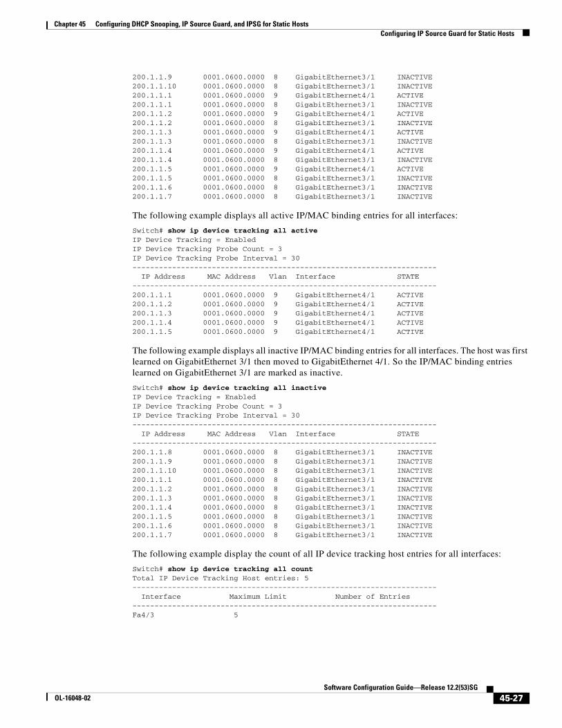
200.1.1.9 0001.0600.0000 8 GigabitEthernet3/1 INACTIVE200.1.1.10 0001.0600.0000 8 GigabitEthernet3/1 INACTIVE200.1.1.1 0001.0600.0000 9 GigabitEthernet4/1 ACTIVE200.1.1.1 0001.0600.0000 8 GigabitEthernet3/1 INACTIVE200.1.1.2 0001.0600.0000 9 GigabitEthernet4/1 ACTIVE200.1.1.2 0001.0600.0000 8 GigabitEthernet3/1 INACTIVE200.1.1.3 0001.0600.0000 9 GigabitEthernet4/1 ACTIVE200.1.1.3 0001.0600.0000 8 GigabitEthernet3/1 INACTIVE200.1.1.4 0001.0600.0000 9 GigabitEthernet4/1 ACTIVE200.1.1.4 0001.0600.0000 8 GigabitEthernet3/1 INACTIVE200.1.1.5 0001.0600.0000 9 GigabitEthernet4/1 ACTIVE200.1.1.5 0001.0600.0000 8 GigabitEthernet3/1 INACTIVE200.1.1.6 0001.0600.0000 8 GigabitEthernet3/1 INACTIVE200.1.1.7 0001.0600.0000 8 GigabitEthernet3/1 INACTIVE
The following example displays all active IP/MAC binding entries for all interfaces:
Switch# show ip device tracking all activeIP Device Tracking = EnabledIP Device Tracking Probe Count = 3IP Device Tracking Probe Interval = 30--------------------------------------------------------------------- IP Address MAC Address Vlan Interface STATE ---------------------------------------------------------------------200.1.1.1 0001.0600.0000 9 GigabitEthernet4/1 ACTIVE200.1.1.2 0001.0600.0000 9 GigabitEthernet4/1 ACTIVE200.1.1.3 0001.0600.0000 9 GigabitEthernet4/1 ACTIVE200.1.1.4 0001.0600.0000 9 GigabitEthernet4/1 ACTIVE200.1.1.5 0001.0600.0000 9 GigabitEthernet4/1 ACTIVE
The following example displays all inactive IP/MAC binding entries for all interfaces. The host was first learned on GigabitEthernet 3/1 then moved to GigabitEthernet 4/1. So the IP/MAC binding entries learned on GigabitEthernet 3/1 are marked as inactive.
Switch# show ip device tracking all inactiveIP Device Tracking = EnabledIP Device Tracking Probe Count = 3IP Device Tracking Probe Interval = 30--------------------------------------------------------------------- IP Address MAC Address Vlan Interface STATE ---------------------------------------------------------------------200.1.1.8 0001.0600.0000 8 GigabitEthernet3/1 INACTIVE200.1.1.9 0001.0600.0000 8 GigabitEthernet3/1 INACTIVE200.1.1.10 0001.0600.0000 8 GigabitEthernet3/1 INACTIVE200.1.1.1 0001.0600.0000 8 GigabitEthernet3/1 INACTIVE200.1.1.2 0001.0600.0000 8 GigabitEthernet3/1 INACTIVE200.1.1.3 0001.0600.0000 8 GigabitEthernet3/1 INACTIVE200.1.1.4 0001.0600.0000 8 GigabitEthernet3/1 INACTIVE200.1.1.5 0001.0600.0000 8 GigabitEthernet3/1 INACTIVE200.1.1.6 0001.0600.0000 8 GigabitEthernet3/1 INACTIVE200.1.1.7 0001.0600.0000 8 GigabitEthernet3/1 INACTIVE
The following example display the count of all IP device tracking host entries for all interfaces:
Switch# show ip device tracking all countTotal IP Device Tracking Host entries: 5--------------------------------------------------------------------- Interface Maximum Limit Number of Entries ---------------------------------------------------------------------Fa4/3 5
45-27Software Configuration Guide—Release 12.2(53)SG
OL-16048-02
Chapter 45 Configuring DHCP Snooping, IP Source Guard, and IPSG for Static HostsConfiguring IP Source Guard for Static Hosts
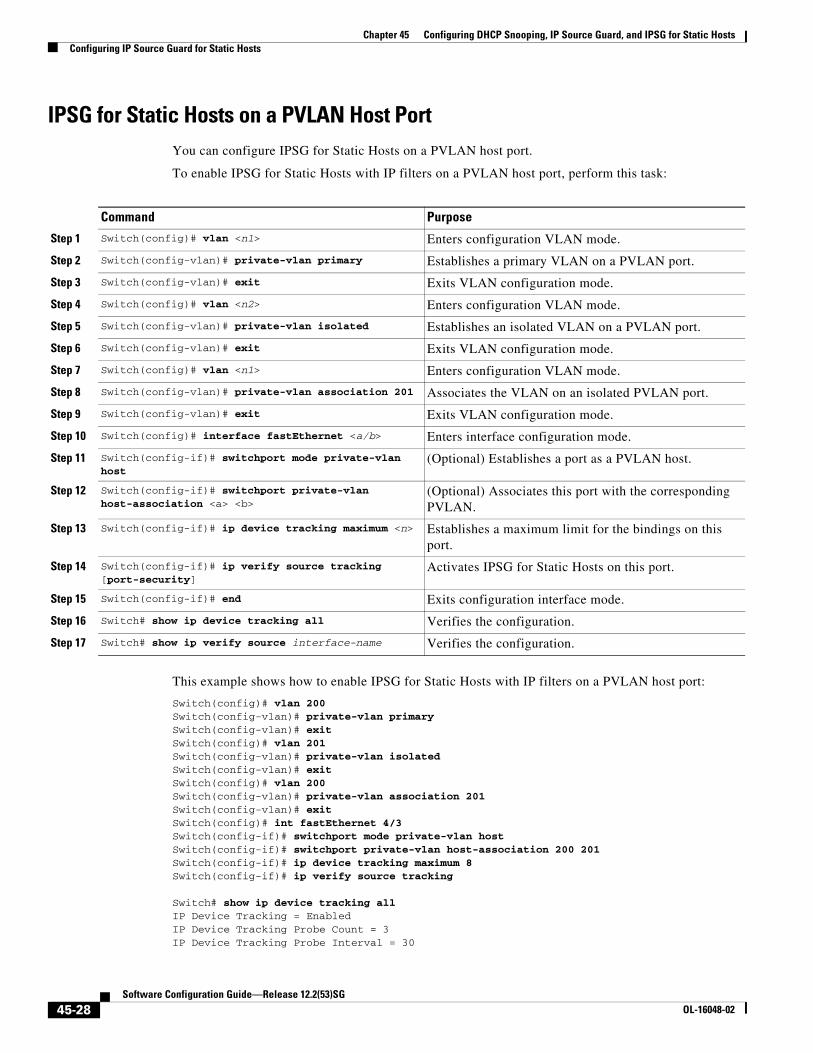
IPSG for Static Hosts on a PVLAN Host PortYou can configure IPSG for Static Hosts on a PVLAN host port.
To enable IPSG for Static Hosts with IP filters on a PVLAN host port, perform this task:
This example shows how to enable IPSG for Static Hosts with IP filters on a PVLAN host port:
Switch(config)# vlan 200Switch(config-vlan)# private-vlan primarySwitch(config-vlan)# exitSwitch(config)# vlan 201Switch(config-vlan)# private-vlan isolated Switch(config-vlan)# exitSwitch(config)# vlan 200Switch(config-vlan)# private-vlan association 201Switch(config-vlan)# exitSwitch(config)# int fastEthernet 4/3Switch(config-if)# switchport mode private-vlan host Switch(config-if)# switchport private-vlan host-association 200 201Switch(config-if)# ip device tracking maximum 8Switch(config-if)# ip verify source tracking
Switch# show ip device tracking allIP Device Tracking = EnabledIP Device Tracking Probe Count = 3IP Device Tracking Probe Interval = 30
Command Purpose
Step 1 Switch(config)# vlan <n1> Enters configuration VLAN mode.
Step 2 Switch(config-vlan)# private-vlan primary Establishes a primary VLAN on a PVLAN port.
Step 3 Switch(config-vlan)# exit Exits VLAN configuration mode.
Step 4 Switch(config)# vlan <n2> Enters configuration VLAN mode.
Step 5 Switch(config-vlan)# private-vlan isolated Establishes an isolated VLAN on a PVLAN port.
Step 6 Switch(config-vlan)# exit Exits VLAN configuration mode.
Step 7 Switch(config)# vlan <n1> Enters configuration VLAN mode.
Step 8 Switch(config-vlan)# private-vlan association 201 Associates the VLAN on an isolated PVLAN port.
Step 9 Switch(config-vlan)# exit Exits VLAN configuration mode.
Step 10 Switch(config)# interface fastEthernet <a/b> Enters interface configuration mode.
Step 11 Switch(config-if)# switchport mode private-vlan host
(Optional) Establishes a port as a PVLAN host.
Step 12 Switch(config-if)# switchport private-vlan host-association <a> <b>
(Optional) Associates this port with the corresponding PVLAN.
Step 13 Switch(config-if)# ip device tracking maximum <n> Establishes a maximum limit for the bindings on this port.
Step 14 Switch(config-if)# ip verify source tracking [port-security]
Activates IPSG for Static Hosts on this port.
Step 15 Switch(config-if)# end Exits configuration interface mode.
Step 16 Switch# show ip device tracking all Verifies the configuration.
Step 17 Switch# show ip verify source interface-name Verifies the configuration.
45-28Software Configuration Guide—Release 12.2(53)SG
OL-16048-02
Chapter 45 Configuring DHCP Snooping, IP Source Guard, and IPSG for Static HostsConfiguring IP Source Guard for Static Hosts
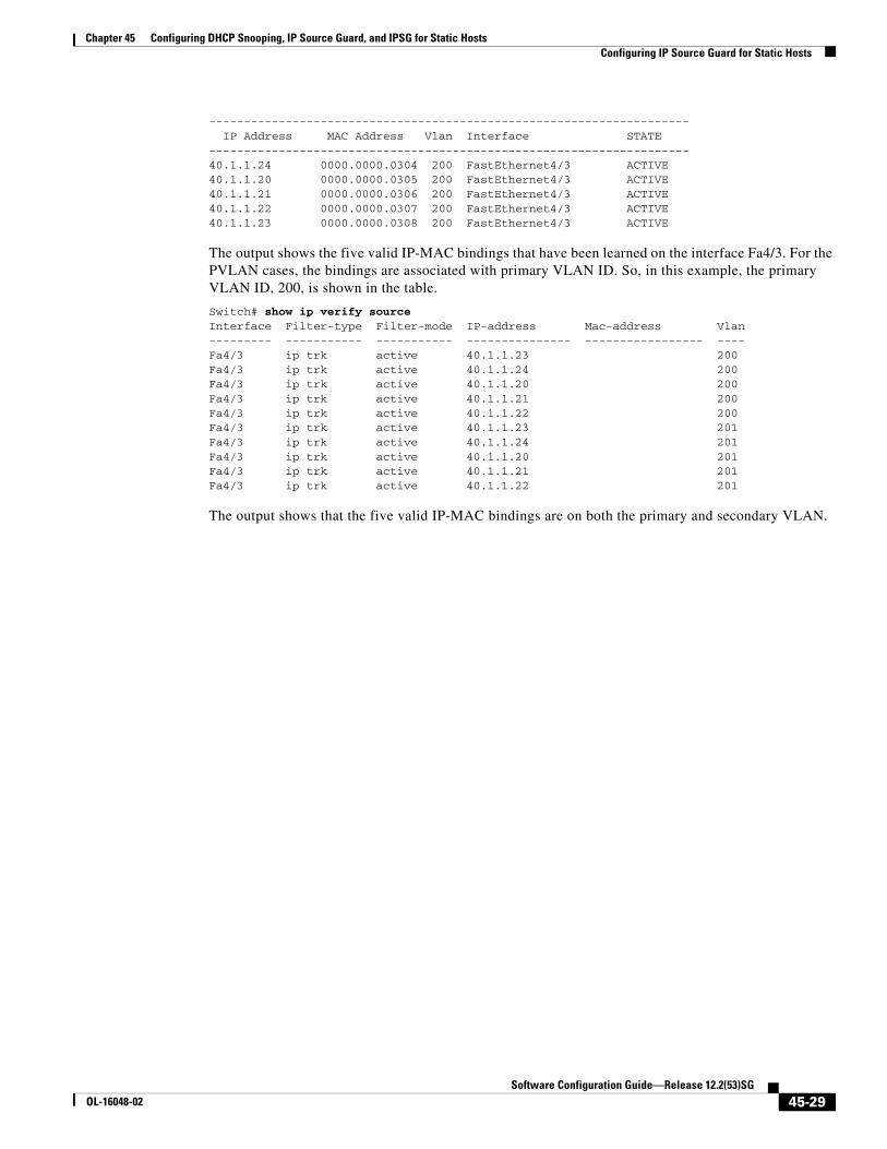
--------------------------------------------------------------------- IP Address MAC Address Vlan Interface STATE ---------------------------------------------------------------------40.1.1.24 0000.0000.0304 200 FastEthernet4/3 ACTIVE40.1.1.20 0000.0000.0305 200 FastEthernet4/3 ACTIVE40.1.1.21 0000.0000.0306 200 FastEthernet4/3 ACTIVE40.1.1.22 0000.0000.0307 200 FastEthernet4/3 ACTIVE40.1.1.23 0000.0000.0308 200 FastEthernet4/3 ACTIVE
The output shows the five valid IP-MAC bindings that have been learned on the interface Fa4/3. For the PVLAN cases, the bindings are associated with primary VLAN ID. So, in this example, the primary VLAN ID, 200, is shown in the table.
Switch# show ip verify sourceInterface Filter-type Filter-mode IP-address Mac-address Vlan--------- ----------- ----------- --------------- ----------------- ----Fa4/3 ip trk active 40.1.1.23 200 Fa4/3 ip trk active 40.1.1.24 200 Fa4/3 ip trk active 40.1.1.20 200 Fa4/3 ip trk active 40.1.1.21 200 Fa4/3 ip trk active 40.1.1.22 200 Fa4/3 ip trk active 40.1.1.23 201 Fa4/3 ip trk active 40.1.1.24 201 Fa4/3 ip trk active 40.1.1.20 201 Fa4/3 ip trk active 40.1.1.21 201 Fa4/3 ip trk active 40.1.1.22 201
The output shows that the five valid IP-MAC bindings are on both the primary and secondary VLAN.
45-29Software Configuration Guide—Release 12.2(53)SG
OL-16048-02

Chapter 45 Configuring DHCP Snooping, IP Source Guard, and IPSG for Static HostsConfiguring IP Source Guard for Static Hosts
45-30Software Configuration Guide—Release 12.2(53)SG
OL-16048-02