sli 15 quick install guide - home - unipower powering technology sli 15 inverter installation to the...
TRANSCRIPT
2
P O W E R I N G T E C H N O L O G Y
SLI 15 Inverter Installationto the Power Supply System - Quick Install Guide
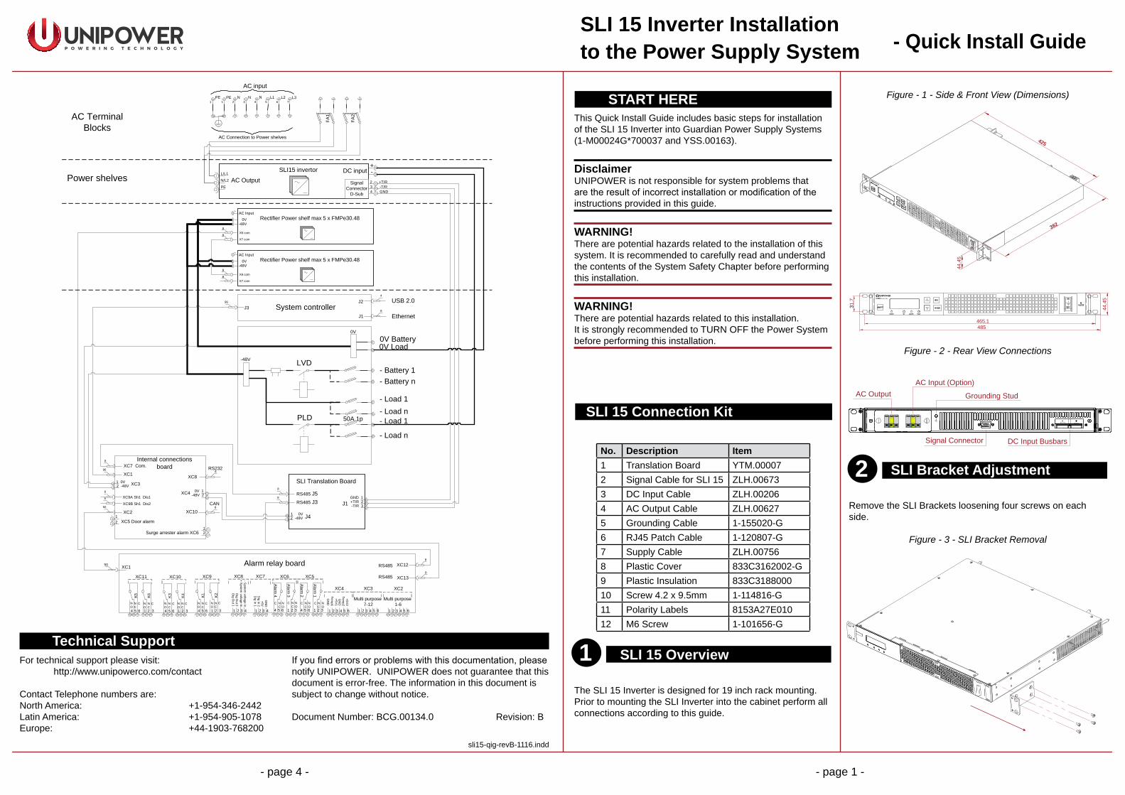
START HEREThis Quick Install Guide includes basic steps for installationof the SLI 15 Inverter into Guardian Power Supply Systems(1-M00024G*700037 and YSS.00163).
DisclaimerUNIPOWER is not responsible for system problems that are the result of incorrect installation or modification of the instructions provided in this guide.
WARNING!There are potential hazards related to the installation of thissystem. It is recommended to carefully read and understandthe contents of the System Safety Chapter before performingthis installation.
WARNING!There are potential hazards related to this installation.It is strongly recommended to TURN OFF the Power Systembefore performing this installation.
SLI 15 Connection Kit
No. Description Item1 Translation Board YTM.000072 Signal Cable for SLI 15 ZLH.006733 DC Input Cable ZLH.002064 AC Output Cable ZLH.006275 Grounding Cable 1-155020-G6 RJ45 Patch Cable 1-120807-G7 Supply Cable ZLH.007568 Plastic Cover 833C3162002-G9 Plastic Insulation 833C318800010 Screw 4.2 x 9.5mm 1-114816-G11 Polarity Labels 8153A27E01012 M6 Screw 1-101656-G
SLI 15 Overview
The SLI 15 Inverter is designed for 19 inch rack mounting.Prior to mounting the SLI Inverter into the cabinet perform allconnections according to this guide.
1
Figure - 1 - Side & Front View (Dimensions)
485465,1
44,4
5
44,4
5
331,7
382
425
Figure - 2 - Rear View Connections
AC OutputAC Input (Option)
Grounding Stud
Signal Connector DC Input Busbars
+-
SLI Bracket Adjustment
Remove the SLI Brackets loosening four screws on each side.
Figure - 3 - SLI Bracket Removal
Technical SupportFor technical support please visit: http://www.unipowerco.com/contact
Contact Telephone numbers are:North America: +1-954-346-2442Latin America: +1-954-905-1078Europe: +44-1903-768200
If you find errors or problems with this documentation, pleasenotify UNIPOWER. UNIPOWER does not guarantee that thisdocument is error-free. The information in this document issubject to change without notice.
Document Number: BCG.00134.0 Revision: B
sli15-qig-revB-1116.indd
- page 4 - - page 1 -
-48V
- Battery 1- Battery n
0V Load
- Load 1- Load n
Power shelves
LVD
USB 2.04
J2
8
96
J1
J3
Ethernet System controller
96XC1
Internal connections board
1 0V2 -48V
XC9A Sh1 Dis1
XC9B Sh1 Dis2
XC7 Com.8
XC88
-48V 20V 1
RS232
XC250
XC3
XC5 Door alarm1
12
2
6
6XC4
8XC10
CAN
Surge arrester alarm XC6
0V Battery0V
+-SLI15 invertor
L/L1
N/L2
PEAC Output
DC input
8
RS485 J3
SLI Translation Board
1 0V2 -48V
RS485 J58
+T/R 2GND 1
J4
J1 -T/R 3
Rectifier Power shelf max 5 x FMPe30.480V-48V
8
8X6 com
X7 com
15
AC Input
Rectifier Power shelf max 5 x FMPe30.480V-48V
8
8X6 com
X7 com
15
AC Input
321
Alarm1
654
Alarm2
321
Alarm3
654
Alarm4
XC6 XC5
654
Multi purpose 1-6
XC2
321654
XC3
321
Multi purpose 7-12
654321
XC4
Temp1
Temp2
+5V1
+5V2
GN
D
GN
D
4321
XC7
Dig
In1
Dig
In2
+5VG
ND
4321
XC8
Dig
Out1
Dig
Out2
+System
voltageIn.
-Systemvoltage
In.
NC
CNO
21654 3
K1 K2
XC9
21654 3
K3 K4
XC10
21654 3
K5 K6
XC11
NC
CNO
NC
CNO
NC
CNO
NC
CNO
NC
CNO
NC
C NO
NC
C NO
NC
C NO
NC
C NO
50 XC1 XC128
RS485
XC138
RS485
Alarm relay board
- Load 1
- Load n
L1NPE NPE L2 L3
AC input
AC Connection to Power shelves
N1 1 2 3 4 5 6 7
PLD
FA1
FA2AC Terminal
Blocks
50A 1p
Signal Connector
D-Sub 432
GND-T/R+T/R

8
7
6
4
P O W E R I N G T E C H N O L O G Y
SLI 15 Inverter Installationto the Power Supply System - Quick Install Guide
- page 2 - - page 3 -
Attach the Brackets back to the SLI according to therequirements of the system.
Figure - 4 - M24*700037
Figure - 5 - YSS.00163
Grouding Connection
WARNINGPrior to installation to the system the SLI 15 must be properlygrounded.
Connect the Grounding cable to the Grounding stud on therear side of SLI Inverter (cable lug M5). Route the cable to the grounding terminal of corresponding cabinet, see Figures 6 & 7.
3
Figure - 6 - Top Right Side of the CabinetM24*700037
Figure - 7 - Bottom Right Side of CabinetYSS.00163
DC Input ConnectionUntighten two screws and remove existing plastic insulationfrom DC busbars. Attach the new plastic insulation (9) andtighten with original screws.
Connect the Negative (blue) and the Positive (black) cables (3) to the SLI DC Input busbar (Figure 2) using M6 screws.Route the cables to DC Distribution and connect the Negative (blue) cable to 50A Breaker and Positive (black) to 0V Busbar.
NOTEFor correct selection of breakers, see Distribution layout inAppendix A of Instruction Manual.
Attach the plastic cover (8), used for insulating the DC Input, to the DC Input Busbar (A), close (B) and tighten with screw (10) (C). Stick the polarity labels (11) on the plastic cover and insulation (9).
Figure - 8
A
B
C
Communication Interface
NOTEAll connections must be performed according to Schematicdiagram on page 4 of this Quick Install Guide.
1. Install the SLI Translation Board (1) onto the DIN rail next to the AC Mains Terminal Block (rear wall of cabinet M24*700037 or rear side of PBDU - YSS.00163). See Figure 9.
2. Connect the Signal Cable (2) to the Signal Connector (type D-sub) on the rear side of the SLI and tighten with two screws M2.5.
3. Connect the other end of the Signal Cable to the SLI Translation Board (J1) (2).
4. Connect the 48V supply cable (7) from the Internal Connection Board (XC4) to the SLI Translation Board (J4).
5. Disconnect the RS485 communication cable from the Internal connection board (XC7) and connect it to the SLI Translation Board (J5). Connect RS485 communication cable to SLI Translation Board (J3) and the other end to Internal connection board (XC7).
WARNINGThe SLI Translation Board must be supplied with system voltage (48V) otherwise the power source for the RS485 might be damaged.
AC Output Connection
Connect the output cable (4) from the SLI AC Output terminals to the AC Load Breaker (FA1 and FA2) situated on the AC Mains Input Terminal Block (Figure 9).
Figure - 9
SLI Transl. Board
AC Mains Terminal Block
J1
J4 J5 J3
3x400V AC
multi 9C60NC50230/400V6000
3
MERLIN GERIN
1
2
3
4
I ON I ON
multi 9C60NC50230/400V6000
3
MERLIN GERIN
1
2
3
4
I ON I ON
FA 2FA 1L1 L2 L3NPEPE N N
5 SLI Mounting to the Cabinet
Mount the SLI unit into the cabinet and tighten with four M6 screws (12).
Figure - 10 - M24*700037 shown
SLI Commissioning
NOTEIt is highly recommended to read thought the SLI 15 SeriesUser Guide for correct SLI unit settings.
NOTEMake sure all connections are made according to the Schematic diagram on page 4.
1. Switch ON the Power System and the SLI unit (Battery breaker, AC Input Breaker, SLI Input breaker on the PBDU and also the SLI front panel switch).
2. Check the output parameter settings on the SLI panel.3. Verify the output voltage on the AC Load breaker.4. Switch ON the FA4 breaker and connect the load.5. Connect the PC to the control unit via the PowCom™
software and verify the SLI reading (voltage, current, power and alarms). The SLI data can be verified via SNMP or directly on the ACC Extended (ACX) Controller front panel.