skf angular contact ball bearings – your key to longer service life s
TRANSCRIPT

SKF angular contact ball bearings – Your key to longer service life
s

2
Contents
1Product information .................................................. 3
Diversity and quality ...................................................... 3Why specify angular contact ball bearings?................. 3Why specify SKF angular contact ball bearings?......... 3
Advantages by design with SKF Explorer Bearings. ......................................... 4
Technical improvements .............................................. 4Identification symbols................................................... 5Availability .................................................................... 5
Advantages for your design: higher performance with Explorer bearings................ 6
Longer service life ........................................................ 6New designs with smaller bearings.............................. 7New designs with higher power density ....................... 7
Efficient in all industrial segments ............................... 8
2 Recommendations .................................................. 10
Selection of bearing size ............................................... 10Bearing life ................................................................... 10Load carrying capacity of paired single-row bearings...................................................... 11Equivalent dynamic bearing load ................................. 12Equivalent static bearing load ...................................... 12Determination of axial force for bearings mounted singly or paired in tandem............................. 12
Design of bearing arrangements .................................. 14Mounting and dismounting ........................................... 16
Mounting ...................................................................... 16Dismounting ................................................................. 17
Service for a lasting partnership .................................. 18
3 Product data ............................................................ 19
Single-row angular contact ball bearings .................... 19General bearing data ................................................... 19Assortment ................................................................... 22Product table................................................................ 24
Double-row angular contact ball bearings................... 30General bearing data ................................................... 30Assortment ................................................................... 34Product table................................................................ 36
Made by SKF® stands for excellence. It symbolises our consistent endeavour to achieve total quality in everything we do. For those who use our products, “Made by SKF” implies three main benefits.
Reliability – thanks to modern, efficient products, based on our worldwide application know-how, opti-mised materials, forward-looking designs and the most advanced production techniques.
Cost effectiveness – resulting from the favourable ratiobetween our product quality plus service facilities, and the purchase price of the product.
Market lead – which you can achieve by taking advantage of our products and services. Increased operating time and reduced down-time, as well as improved output and product quality are the key to a successful partnership.
Other SKF angular contact ball bearings ................. 40
The SKF Group – a worldwide corporation .............. 42

3
1
1 Product information 2 Recommendations 3 Product data
Customer benefits Page ............. 10 Page ............. 19
Why specify angularcontact ball bearings?High rotating speeds, combined radialand axial loads, a high degree of stiff-ness and running accuracy – these arethe conditions where angular contactball bearings are the preferred solution.The great variety of applications andoperating conditions calls for custo-mized bearing solutions made possibleonly by a wide range of angular contactball bearings.
Why specify SKF angularcontact ball bearings?Because SKF is your reliable, expertsource for angular contact ball bear-ings. Because SKF has a wide rangeof types and variants unmatched any-where else. Because when you workwith SKF you don’t have to settle forany unfavourable compromises.Because since the introduction of ourbearings of BE design in 1984, theyhave set the standard for single-rowangular contact ball bearings. Sincethen, time certainly hasn’t stood still,and neither has SKF.
The best example: our Explorer se-ries single-row and double-row angular
contact ball bearings offering a com-pletely new level of performance. WithSKF angular contact ball bearings, youbenefit in a number of ways:
High performanceThey have a high load carrying capa-city and thus allow smaller bearings tobe used while still providing long ser-vice life.
Quieter and cooler running With their optimal inner geometry, theyrun quieter and cooler and can toleratelonger maintenance intervals.
Precise shaft guidanceDue to precision manufacturing pro-cesses, almost all SKF angular con-tacts exceed standard tolerances, toprovide a smoother, truer running shaftwith less heat and fewer vibrations.
High temperature capabilityThey can withstand relatively high ope-rating temperatures without significantloss of dimensional stability.
Universal matchingAt SKF, universally matchable single-row angular contact ball bearings arestandard. These bearings simplifyassembly and can also increase thequality of your products. Our selectionof clearance and preload classescovers all possible requirements.
Integral sealing solutionsDouble-row angular contact ball bear-ings are available with integral sealsand shields. These bearings are sup-plied with grease and do not requiremaintenance.
Standard solutionsIt will be hard to find an application forwhich there’s no standard SKF bearingreadily available from our vast selec-tion and enormous variety.
Customer satisfactionNow you can build additional value intoyour products with SKF Explorer bear-ings. Your customers will definitely beimpressed by the low operating costs,reliability and long service life of yourmachines – no doubt in part to youruse of SKF bearings.
Diversity and quality

4
1 Product information 2 Recommendations 3 Product data
New design Page ............. 10 Page ............. 19
At SKF we’re continuously working toimprove the performance and durabilityof our products. And with the newExplorer Series angular contact ballbearings, we think you’ll notice the dif-ference immediately. These bearingscan provide:
● Even longer service life,● Even higher reliability,● Even more performance.
The following pages will describe theimprovements we have made to ourangular contact ball bearings in the 72 and 73 Series and in the 32 and 33 Series (52/53 Series US only).
Technical improvementsImproved materialsExplorer angular contact ball bearingsare manufactured from an extremelyhigh quality bearing steel with a verylow oxygen content and a minimumnumber of impurities. The rings aremanufactured preferably from forgedor cold rolled blanks.
All rings are heat treated to providedimensional stability up to 150 °C (300 °F). The advantage of this: Bear-ing sets build with SKF single-rowangular contact ball bearings holdtheir built-in clearances and preloadsmore exactly over their entire lifetime (➔ diagram ).
Improved inner geometryComputer-aided design and manufac-turing programs permit almost unde-tectable improvements in the bearing.These small but effective changes inthe bearing’s geometry lead to measu-rable improvements in performanceand service life. One effect of this finetuning: Explorer angular contact ballbearings are less sensitive to eventualaxial overloading.
1
More precise shaft guidanceExplorer single-row bearings aremanufactured to P5 running accuracy.Explorer double-row bearings aremanufactured to P6 running accuracy.
Better ball qualityThe balls used in Explorer angularcontact ball bearings are oneISO grade better than before.The more uniform ball dia-meter helps to improverunning accuracy even athigh speeds, while redu-cing noise and operatingtemperature.
New cagesExplorer single-row bearingshave solid cages made frompolyamide or brass. Polyamidecages have been improved to betterwithstand high accelerations. Brasscages are manufactured to closer tole-
Advantages by design with SKFExplorer Bearings
0,015
0,010
0,005
0
-0,010
-0,015
-0,020
-0,005
10 100 1000 10000
Explorer 7307 BECB Standard 7307 BECB
Explorer 3310 A/C3 Standard 3310 A/C3
Explorer 7307 BEGA
Standard 7307 BEGA
1Diagram
Change of the residual bearing clearance/preload during operation
Operating hours
Cle
aran
ce, m
mP
relo
ad, m
m
Examples: 7307 BE, Fa/Fr = 1.23, C/P = 29, operating temperature 110°C (230°F)3310 A/C3, Fa/Fr = 1.23, C/P = 19, operating temperature 80°C (175°F)

5
1
1 Product information 2 Recommendations 3 Product data
New design Page ............. 10 Page ............. 19
rances and have been improved toprovide better ball guidance and maxi-mize the effects of the lubricant underall operating conditions.
Explorer double-row bearings areavailable as standard with a newly-developed crown cage made of sheetsteel.
Effective sealsDouble-row angular contact ball bear-ings are available with seals or shields.Explorer bearings use a new shielddesign (➔ fig ). A new simple laby-rinth keeps contaminants out andretains grease in the bearing cavity.
Identification symbolsExplorer angular contact ball bearingsare not an extension of the assortment.They replace final variants of theprevious types. And because it is easi-er for inventory management, their partnumbers remain the same. Neverthe-less, Explorer bearings can be recogni-sed easily.
1
PackagingExplorer bearings come in a uniquepackage, so that they can be recogni-sed immediately as Explorer bearings.
Laser inscriptionA new feature of the Explorer bearingsis their laser inscription. It is not onlymore legible, but also more environ-mentally friendly because acids are nolonger required for etching. It also per-mits individual markings. Dependingon the requirements in Quality Assur-ance, the bearings can be traced pre-cisely.
AvailabilityThe introduction of the Explorer angu-lar contact ball bearings has begun.The mayority of the single row bear-ings have already been converted andare now available only for delivery inthe Explorer design, while Explorerdouble-row bearings will be introducedby the end of the third quarter of 2002.In this brochure, the bearings whichare available in Explorer design as wellas these where conversion is foreseenare marked as Explorer bearings.
Explorer angular contact ballbearings
• Improved materials• Optimised internal geometry• Higher precision• Higher ball quality• Improved cages• Single bearings which can be
paired universally• New shields for double-row
bearings
Shielded Explorer double-row angularcontact ball bearing
1Fig
6
1 Product information 2 Recommendations 3 Product data
New performance class Page ............. 10 Page ............. 19
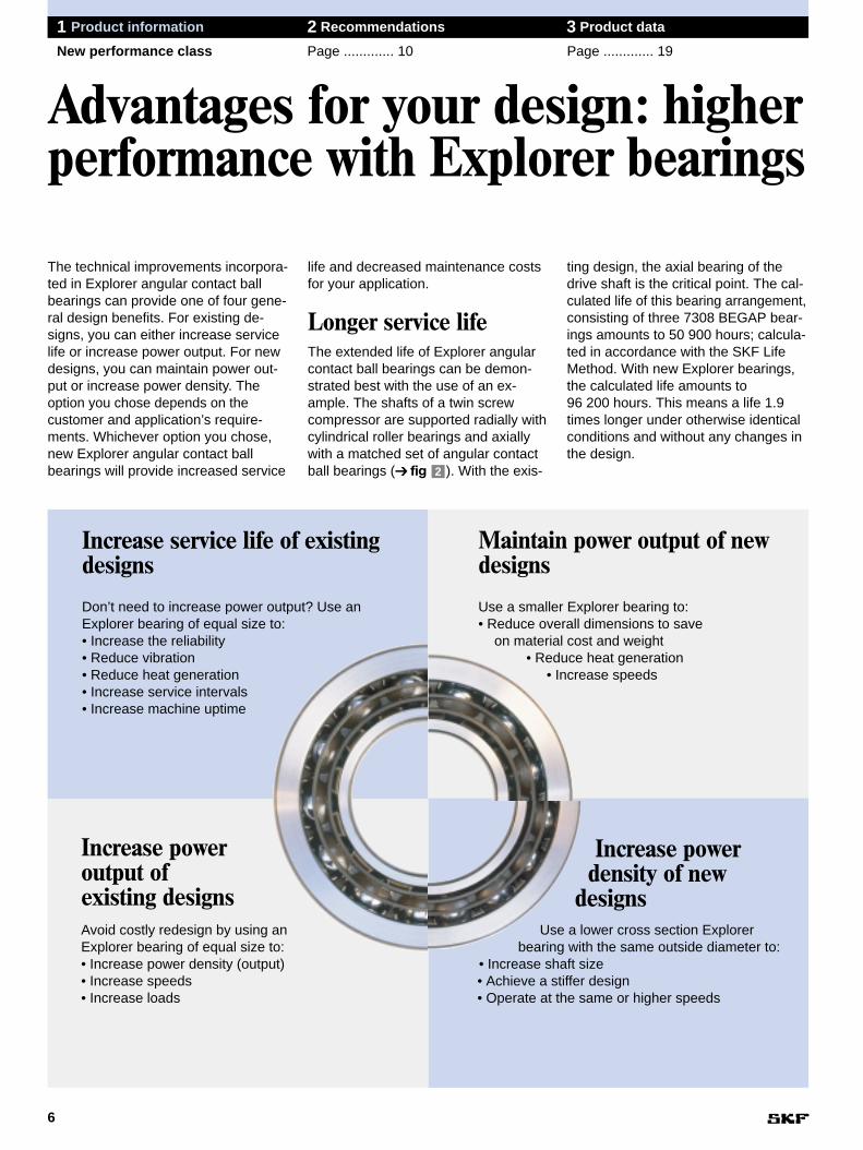
The technical improvements incorpora-ted in Explorer angular contact ballbearings can provide one of four gene-ral design benefits. For existing de-signs, you can either increase servicelife or increase power output. For newdesigns, you can maintain power out-put or increase power density. Theoption you chose depends on thecustomer and application’s require-ments. Whichever option you chose,new Explorer angular contact ballbearings will provide increased service
life and decreased maintenance costsfor your application.
Longer service lifeThe extended life of Explorer angularcontact ball bearings can be demon-strated best with the use of an ex-ample. The shafts of a twin screw compressor are supported radially withcylindrical roller bearings and axiallywith a matched set of angular contactball bearings (➔ fig ). With the exis-2
ting design, the axial bearing of thedrive shaft is the critical point. The cal-culated life of this bearing arrangement,consisting of three 7308 BEGAP bear-ings amounts to 50 900 hours; calcula-ted in accordance with the SKF LifeMethod. With new Explorer bearings,the calculated life amounts to 96 200 hours. This means a life 1.9times longer under otherwise identicalconditions and without any changes inthe design.
Advantages for your design: higherperformance with Explorer bearings
Increase service life of existingdesigns
Don’t need to increase power output? Use anExplorer bearing of equal size to:• Increase the reliability• Reduce vibration• Reduce heat generation• Increase service intervals• Increase machine uptime
Maintain power output of newdesigns
Use a smaller Explorer bearing to:• Reduce overall dimensions to save
on material cost and weight• Reduce heat generation
• Increase speeds
Increase poweroutput ofexisting designsAvoid costly redesign by using anExplorer bearing of equal size to:• Increase power density (output)• Increase speeds• Increase loads
Increase powerdensity of new
designsUse a lower cross section Explorer
bearing with the same outside diameter to:• Increase shaft size• Achieve a stiffer design• Operate at the same or higher speeds

7
1
1 Product information 2 Recommendations 3 Product data
New performance class Page ............. 10 Page ............. 19
New designs with smaller bearingsIn many cases where 73 Series bear-ings are used, it will be possible to use72 Series bearings in the future. Evenwith a smaller bearing, a longer bear-ing life will be possible. Table 1 showssome suitable examples.
Without changes to the shaft, bear-ing arrangements can also be designedmore compactly. Explorer bearingspermit lighter structures with the samecapacity.
New designs with higherpower densityIf the outside diameter of the bearingremains unchanged, the transition from73 Series bearings to 72 Series bear-ings will permit the use of strongershafts (➔ table ).
With otherwise unchanged parts,more rigid designs with higher powerdensity are possible. And the servicelife of the bearing will be increased significantly.
1
Twin-screw compressor bearing arrangement
Comparison of Explorer and conventional bearings – possible downsizing
2Fig
Previous Explorer Cross section Benefit lifebearing bearing AExpl x 100
L10m,Expl
Aprev. L10m,prev.
Same bore 7306 BE 7206 BE 64 % 1,0diameter
7308 BE 7208 BE 63 % 1,2
7319 BE7219 BE 51 % 1,1
Same outer 7304 BE 7205 BE 84 % 1,7diameter
7308 BE 7210 BE 70 % 1,6
7313 BE 7216 BE 63 % 1,5
1Table
1 Product information 2 Recommendations 3 Product data

8
1 Product information 2 Recommendations 3 Product data
Application Examples Page ............. 10 Page ............. 19
Lower friction, quieter running and,above all, their reliability in complexapplications with combined loads makeSKF angular contact ball bearingsindispensable in many areas. Longservice life and reliable performancehave earned SKF angular contact ballbearings an excellent reputation in avariety of industries ranging from gear-boxes to turbines.
Nevertheless, the most commonapplications for SKF angular contactball bearings are pumps and compres-sors. These applications are not justthe most common, they are also themost demanding. For example, the
bearings used in both pumps andcompressors must be able to accommo-date combined axial and radial loads,high speeds, poor lubrication and contaminated conditions.
The improvements made to the newExplorer bearings were aimed primarilyat the demanding requirements of bothpumps and compressors. For theseapplications a recommended productrange is available. Additional informa-tion can be found in publication No.4872: “Recommended Product Range:SKF angular contact ball bearings forpumps and compressors”.
Efficient in all industrial segments
Industrial segments
• Fluid machinery:Pumps, compressors, blowers,ventilators, turbines
• Automotive engineering:Drives, clutches, gearboxes,wheel bearings, components
• Industrial drives and drive motors• Printing machines• Textile machines• Material handling
Requirements
• Long service life• High load-carrying capacity and
high speeds• High degree of stiffness• High degree of running accuracy• Low heat generation• Quiet running• Technical support
Solution

9
1

10
1 Product information 2 Recommendations 3 Product data
Page ............. 3 Bearing size Page ............. 19
Selection of bearing size
Bearing life can be calculated easilyusing the programs found in the “SKFInteractive Engineering Catalog.”Explorer bearing data will be added tothe online version at www.skf.com.
Bearing lifeThe life-extending improvements,embodied in SKF explorer bearingscan best be understood using the SKF Life Method. This life calculationmethod constitutes an extension of the fatigue life theory developed byLundberg and Palmgren and is betterable to predict bearing life. The LifeMethod was first presented by SKF in1989 and today standardised in ISO281:1990/ Amd.2:2000. The modifiedrating life for angular contact ball bear-ings can be calculated from:
L10m = a1 aSKF L10
or
L10m = a1 aSKF (C)3
P
With a constant rotational speed, thelife in operating hours can be calcula-ted from the following formula:
L10mh = a1 aSKF1 000 000 (C)3
60 n P
Where: L10m = modified rating life, millions of
revolutionsL10mh = modified rating life, operating
hoursL10 = basic rating life, millions of
revolutionsa1 = life adjustment factor for relia-
bility (for 90% reliability a1 = 1,according to ISO 281)
aSKF = life modification factor basedon the SKF Life Method,(➔ Diagrams and )
C = basic dynamic load rating, NP = equivalent dynamic bearing
load, Nn = rotational speed, r/min
21
Life modification factor aSKF for conventional radial ball bearings
0,005 0,01 0,02 0,050,05
0,1
0,1
0,2
0,2
0,5
0,5
1
1
2
2
5
10
20
50
5
aSKF
ηcPPu––
κ =
42
10,
8
0,5
0,3
0,15
κ=0,1
0,2
0,4
0,6
1Diagram
If κ > 4, use κ = 4 curveAs the value of ηc (Pu/P) tends to zero, aSKF tends to 0,1 for all values of κ

11
2
1 Product information 2 Recommendations 3 Product data
Page ............. 3 Bearing size Page ............. 19
Life modification factor aSKFThe SKF Life Method takes intoaccount the complex relationshipsbetween different factors influencingbearing life. These factors have beensimplified so that they can be insertedinto your calculations. Diagram 1 con-tains the life modification factor forstandard SKF angular contact ballbearing designs. Diagram 2 containsthe values for Explorer bearings. Thevalues are given as a function of
• the viscosity ratio κ,• the ratio of the fatigue load limit to the
applied equivalent load (Pu/P),• the cleanliness in the bearings (ηc).
Guideline values for the selection ofηc are given in Table .
Diagrams and are based onthe general safety factors typicallyassociated with the fatigue load limitsfor other mechanical components. Thediagrams are valid for lubricants with-out EP additives. If lubricants with EPadditives are used, see the informationin the SKF General Catalogue or in the“SKF Interactive EngineeringCatalogue“ on CD-ROM or online atwww.skf.com.
Load carrying capacityof paired single-rowbearingsThe values for the basic dynamic andstatic load ratings as well as for thefatigue load limit quoted in the bearingtable on pages 24 to 29 are for singlebearings.
For pairs of universally matchableangular contact ball bearings the basicload ratings C obtained from the tableshould be multiplied by
• 1,62 for bearings in face-to-face orback-to-back arrangement,
• 2 for bearings in tandem arrange-ment.
The basic static load rating and thefatigue load limit of a pair of bearingscan be obtained by multiplying thetable value C0 or Pu by 2.
21
1
0,005 0,01 0,02 0,050,05
0,1
0,1
0,2
0,2
0,5
0,5
1
1
2
2
5
10
20
50
5
aSKF
ηcPPu––
0,6
1
κ=4
0,4
0,3
κ= 0,1
0,15
0,2
0,5
0,8
2
Guide values for the factor ηηc to describe the degree of cleanliness
2Diagram
If κ > 4, use κ = 4 curveAs the value of ηc (Pu/P) tends to zero, aSKF tends to 0,1 for all values of κ
Life modification factor aSKF for Explorer angular contact ball bearings
Condition ηηc1)
Very cleanParticle size of contamination of the order of the lubricant film thickness 1
CleanConditions typical of bearings greased for life and sealed 0,8
NormalConditions typical of bearings greased for life and shielded 0,5
ContaminatedConditions typical of bearings without integral seals; coarse lubricant filters and/or particle ingress from surroundings 0,5 ... 0,1
Heavily contaminated 2) 0
1) The scale for ηc refers only to typical solid contaminants. Contamination by water or other fluids detrimental to bearing life is not included.
2) Under extreme contamination, values of ηc can be outside the scale, resulting in a more severe reduction of life than predicted by the equation for L10m.
1Table

Determining axial forcefor bearings mountedsingly or paired in tan-demAs the load is transmitted from oneraceway to the other at an angle to thebearing axis, an internal axial force willbe induced in single row angular con-tact ball bearings when a radial load isapplied to them. This must be conside-red when calculating the equivalentbearing loads for bearing arrange-ments consisting of two single bear-ings and/or bearing pairs arranged intandem.
The necessary equations are givenin Table for the various bearingarrangements and load cases. Theequations are only valid if the bearingsare adjusted against each other topractically zero clearance, but withoutpreload. In the arrangements shown,bearing A is subjected to a radial loadFrA and bearing B to radial load FrB.Both FrA and FrB are always conside-red positive even when they act in thedirection opposite to that shown in thefigures. The radial loads act at thepressure centres of the bearings, seebearing dimension “a” in the producttable, pages 24 - 29. In addition anexternal force Ka acts on the shaft (oron the housing).
Cases 1c and 2c are also valid whenKa = 0.
2
12
1 Product information 2 Recommendations 3 Product data
Page ............. 3 Bearing size Page ............. 19
Equivalent dynamicbearing loadSingle row bearingsFor single-row B and BE design angu-lar contact ball bearings mounted assingle bearings or paired in tandem:
P = Fr when Fa/Fr ≤ 1,14P = 0,35Fr + 0,57Fa when Fa/Fr > 1,14
When determining the axial load Fa,reference should be made to the chap-ter “Determining axial force for bear-ings mounted singly or paired in tan-dem”.
For pairs of bearings arranged back-to-back or face-to-face:
P = Fr + 0,55Fa when Fa/Fr ≤ 1,14P = 0,57Fr + 0,93Fa when Fa/Fr > 1,14
Fr and Fa are the forces acting on thepair of bearings.
Double-row bearingsFor double-row angular contact ballbearings in the 32 A and 33 A Series:
P = Fr + 0,78Fa when Fa/Fr ≤ 0,80P = 0,63Fr + 1,24Fa when Fa/Fr > 0,80
and for double-row angular contact ballbearings in the 33 DNR Series:
P = Fr + 0,55Fa when Fa/Fr ≤ 1,14P = 0,57Fr + 0,93Fa when Fa/Fr > 1,14
and for double-row angular contact ballbearings in the 33 D Series:
P = Fr + 0,47Fa when Fa/Fr ≤ 1,34P = 0,54Fr + 0,81Fa when Fa/Fr > 1,34
Equivalent static bearingloadSingle row bearingsFor single-row B and BE design angu-lar contact ball bearings mounted assingle bearings or paired in tandem:
P0 = 0,5 Fr + 0,26 Fa
If P0 < Fr then P0 = Fr. When deter-mining the axial load Fa, refer to thechapter “Determining axial force forbearings mounted singly or paired intandem”.
For pairs of bearings arranged back-to-back or face-to-face:
P0 = Fr + 0,52Fa
Fr and Fa are the forces acting on thepair of bearings.
Double-row bearingsFor double-row angular contact ballbearings in the 32 A and 33 A Series:
P0 = Fr + 0,66Fa
and for bearings in the 33 DNR Series:
P0 = Fr + 0,52Fa
and for bearings in the 33 D Series:
P0 = Fr + 0,44Fa

13
2
1 Product information 2 Recommendations 3 Product data
Page ............. 3 Bearing size Page ............. 19
Bearing arrangement Load case Axial forces
Back-to-back Case 1a
FrA ≥ FrB FaA = 0,88 FrA FaB = FaA + Ka
Ka ≥ 0
Case 1b
FrA < FrB FaA = 0,88 FrA FaB = FaA + Ka
Face-to-face Ka ≥ 0,88 (FrB – FrA)
Case 1c
FrA < FrB FaA = FaB – Ka FaB = 0,88 FrB
Ka < 0,88 (FrB – FrA)
Back-to-back Case 2a
FrA ≤ FrB FaA = FaB + Ka FaB = 0,88 FrB
Ka ≥ 0
Case 2b
FrA > FrB FaA = FaB + Ka FaB = 0,88 FrB
Face-to-face Ka ≥ 0,88 (FrA – FrB)
Case 2c
FrA > FrB FaA = 0,88 FrA FaB = FaA – Ka
Ka < 0,88 (FrA – FrB)
B A
Ka
FF
rBrA
A B
Ka
FF
rArB
B A
Ka
FF
rBrA
A B
Ka
FF
rArB
Axial loading of bearing arrangements incorporating two single row B or BE designangular contact ball bearings and/or bearing pairs in tandem.
2Table

14
1 Product information 2 Recommendations 3 Product data
Page ............. 3 Application advice Page ............. 19
Adjusting single-row angular con-tact ball bearingsBecause of their internal design, angu-lar contact ball bearings should not beused single and should always beused with a second bearing or as partof a bearing set (➔ fig and ).
In cases where there are two indivi-dual single-row angular contact ballbearings, they should be adjustedagainst each other until the desiredinternal clearance or the necessarypreload is obtained.
Adjusting clearance or preloadcorrectly is one of the most importantfactors that affects bearing service lifeand the reliability of the bearing ar-rangement (➔ Diagram ). In thecase of excessive clearance, the loadcarrying capacity of the bearings willnot be exploited. This will cause exces-sive noise or skidding between theballs and raceways. In the case ofexcessive preload, higher friction andthe resulting higher operating tempera-tures will reduce bearing service life.
Single-row angular contact ballbearings as bearing setsPaired mounting is used when the loadcarrying capacity is inadequate (tan-
3
21
dem arrangement) or when combinedor axial loads act in both directions(back-to-back and face-to-facearrangements).
When arranged in tandem (➔ fig ), the radial and axial loadsare shared equally by the bearings.However the bearing set can onlyaccommodate axial loads acting inone direction. Axial loads acting inboth directions, as well as combinedloads, require a third bearing adjustedagainst the tandem pair.
Bearings arranged back-to-back (➔ fig ) can accommodate axialloads acting in both directions, but onlyby one bearing in each direction.Bearings mounted back-to-back pro-vide a relatively stiff bearing arrange-ment, which can accommodate tiltingmoments.
Bearings mounted face-to-face (➔ fig ) can accommodate axialloads acting in both directions, but onlyby one bearing in each direction. Thisarrangement is not as stiff as the back-to-back arrangement and is less ableto accommodate tilting moments.
Bearing sets that use universal SKFbearings do not need special shims orfinal adjustments. These bearings are
3c
3b
3a
supplied with the correct preload orclearance manufactured into the bear-ing. To realize these predeterminedvalues, the bearing seat in the housingand on the shaft must be manufac-tured to the correct tolerances.
Favourable load ratios for single-row angular contact ball bearingsFor single-row angular contact ballbearings with a 40° contact angle (de-signation suffix B), the correct rollingconditions will only be achieved in thebearing when the load ratio Fa/Fr ≥ 1.
Design of bearing arrangements
100%
80
60
40
20
120
0
3Diagram
1Fig 2Fig
Bearing arrangement with two individual bearings
Arrangement combinations of universal bearings
Life as a function of clearance or preload
Bearing arrangement with a pair of bearings
3Fig
Life
ClearancePreload
a b c

Bearing Minimum load factorsseries ka kr
72 BE 1,4 9572 B 1,2 8073 BE 1,6 10073 B 1,4 90
32 A - 6033 A - 70
33 D - 9533 DNR - 95
15
2
1 Product information 2 Recommendations 3 Product data
Page ............. 3 Application advice Page ............. 19
Axial loads acting in one directionIn applications where single row bear-ings are mounted back-to-back orface-to-face, axial loads acting predo-minantly in one direction can increasenoise, cause the balls to skid, interruptthe lubricant film or increase cageloads.
To correct this condition, bearingswith zero clearance or a light preloadare typically used. For additional infor-mation, contact your local SKF appli-cation engineering service.
Minimum loadTo obtain maximum performance, aminimum load must be applied to thebearing arrangement. This is particu-larly important in high-speed applica-tions where inertial forces of the balls
and the cage as well as the friction inthe lubricant influence the rolling con-ditions in the bearing to cause slidingmovements (skidding) between theballs and raceways.
For single-row individual bearingsand pairs of bearings in a tandem ar-rangement, the requisite minimum loadcan be calculated as follows:
For pairs of bearings arranged back-to-back or face-to-face as well as fordouble-row bearings, the followingapplies:
Frm = kr ( ν n )2/3x ( dm )2
1000 100
where:Fam = minimum axial load, NFrm = minimum radial load, NC0 = basic static load rating of bearing
or bearing pair respectively, Nka = minimum axial load factor accor-
ding to Tablekr = minimum radial load factor
according to Tableν = oil viscosity at operating tem-
perature, mm2/sn = rotational speed, r/mindm = mean diameter of bearing
= 0,5 (d + D), mm
As a rule, the load is already higherthan the necessary minimum loadthrough the weight of the parts suppor-
3
3
ted and the external forces. If the cal-culated minimum load is not obtained,the bearing must be loaded addition-ally in other ways. In the case of indivi-dual bearings or pairs of bearings in atandem arrangement, an additionalaxial load can be achieved by adjus-ting the inner and outer ring or with theuse of springs. Double-row bearings aswell as bearing sets arranged back-to-back or face-to-face can also be loa-ded radially.
Double-row bearings with shields or sealsBearings with shields are typicallyused in applications where the innerring rotates. In applications where theouter ring rotates, grease (at certainspeeds) can exit between the shieldand the outer ring.
Under extreme conditions, wherethere are high speeds or high oper-ating temperatures, grease can escapebetween the inner ring and seal.
Cage selection criteriaAngular contact ball bearings are avai-lable with different cages. The charac-teristics of the cages and selection cri-teria are summarised in Table .
For more information on cages,which are typically used in bearings forhigh-speed applications, contact yourlocal SKF representative.
4
3Table
Characteristics Cage designInject. moulded Pressed steel Machined Pressed Machined brasspolyamide conventional crowned steel brass
Suffixes P or TN9 J or non J or non F Y M MACage guidance ball ball ball ball ball ball outer ring shoulder
Sliding propertiesof guiding surfaces ++ o + + o + +Lubricant access ++ o ++ + o + - (grease) + (oil)
Weight ++ + + - + - oElasticity ++ o o - o - -Strength - o o ++ o ++ +
Suitable forhigh acceleration o - o - - + ++high temperatures o + + ++ + ++ ++vibration o - o + - + ++high speed o - o o (grease) o + ++
+ (oil) ++ very favourable + favourable o average - unfavourable
4Table
Cage selection chart
Minimum load factors
Fam = kaC0 ( n dm )2
1000 100 000

16
1 Product information 2 Recommendations 3 Product data
Page ............. 3 Mounting Page ............. 19
MountingAngular contact ball bearings are usu-ally mounted with an interference fitonto the shaft. Bearings up to a 50 mmdiameter bore can usually be mountedmechanically. But it is not possible tomount larger bearings when they are“cold” as the force required to mountthe bearing increases considerablywith its size. Therefore, the bearingsshould be heated prior to mounting
When mounting, a clean work envi-ronment is essential since dirt intro-duced into the bearing will dramaticallyaffect the bearing’s service life. In prin-ciple, all bearings should remain in theoriginal packing until immediately be-fore mounting.
Mechanical mounting• Oil the bearing seating surface lightly
with thin oil. • Press the bearing on at right angles
to the shaft axis. • Apply force to the inner ring of the
bearing (➔ fig ).
The SKF TMFT bearing fitting tools aredesigned for quick, precise and safemounting of bearings.
Hot mounting• Heat the bearing with an induction
heater (➔ fig ) or a hotplate. SKFTIH Series induction heaters providehigh quality heating power and con-trol and provide excellent automaticdemagnetisation.
• The required temperature differencebetween bearing inner ring and shaftseating depends on the magnitude ofthe interference fit and the bearing`ssize. Normally a bearing temperatureof 80 to 90 °C (175 to 195 °F) abovethat of the shaft is sufficient for moun-ting. Never heat a bearing to a tem-perature above 125 °C (255 °F).
5
4
• Wear clean protective gloves whenmounting a hot bearing. Push thebearing along the shaft as far as theabutment and hold the bearing inposition, pressing until a tight fit isobtained.
• Heat sealed bearings only by induc-tion heaters, never heat them above80 °C (175 °F) and never use a hot-plate.
After mounting• Check whether the outer ring can be
turned without resistance.• Secure the bearing onto the shaft or
in the housing. • Angular contact ball bearings usually
operate at high speeds. Therefore,grease should fill only about 30% ofthe free space in the bearing´s cavity.
Mounting and dismounting
4Fig 5 Fig
Pressing on at right-angle to the shaftaxis
Induction heater for bearings

17
2
1 Product information 2 Recommendations 3 Product data
Page ............. 3 Mounting Page ............. 19
DismountingDismounting is a potential source ofinternal bearing damage. Dirt mayenter the bearing or errors may bemade during remounting. Thereforeavoid, if possible, dismounting anundamaged bearing.
When dismounting a bearing,arrange for a suitable stop or supportfor the shaft, otherwise the bearingmight be damaged by dismounting forces.
Cleanliness is also important. It iseasier to prevent bearings from be-coming dirty than it is to clean them.Most angular contact ball bearings cannot be separated and are thereforedifficult to clean.
An undamaged bearing should beremounted in the same position in thehousing. Mark the relative position ofeach bearing, i. e. which section of thebearing is up, which side is front etc.
Remove bearings from the shaft• Always use the puller. SKF offers a
comprehensive assortment of suit-able pullers.
• Place the claws of the puller againstthe side face of the inner ring (➔ fig )
• To avoid damage to the bearing seat,the puller should be accuratelycentred. The use of a self-centringpuller eliminates the risk of damageand makes dismounting faster andeasier.
• Only in cases, where it is impossibleto engage the inner ring, should theclaws of the puller be applied to theouter ring. Rotate the outer ring whendismounting so that no part of thebearing is damaged by the dismoun-ting force. To do this lock the screwand rotate the puller continuouslyuntil the bearing comes free (➔ fig ).Note: It is not possible to engage thepuller to the low shoulder of a single-row angular contact ball bearing (➔ fig ). 8
7
6
7Fig 8Fig6Fig
Always place the claws of the puller at the inner ring
Only in exceptional cases apply theclaws of the puller to the outer ring
Never engage the puller at the side of thelow shoulder of the bearing outer ring
Detailed mounting instructions foralmost all SKF rolling bearings areavailable online atwww.skf.com/mount.
18
1 Product information 2 Recommendations 3 Product data
Page ............. 3 Lasting partnership Page ............. 19
Under the proper conditions, bearingscan run for an almost unlimited time.For them to run at least as long as theyshould, operating conditions must beoptimised. At SKF we know our bear-ings and you know your operating con-ditions. Together, as partners SKF canwork with you during the design stageand continue to work with you rightthrough to installation and mainten-ance to keep your machines in peakoperating condition.
SKF concepts for creating customervalueWhy not take advantage of SKF com-petencies for creating customer value?
Decades of troubleshooting experiencein virtually every industrial sectorenables SKF to provide solutions thatimprove machine performance andproductivity. With our Total ShaftSolutions™ concept you can take fulladvantage of our in-depth competencecomprising
• Root cause failure analysis and elimination
• Rotating equipment engineering• Products, services and systems• Machine monitoring
Another SKF concept that embraces a broader view of customer-focused
technologies and competencies is called Asset Efficiency Optimization™,or AEO for short. As the name implies,AEO recognizes the importance of treating machinery and equipment asplant assets. SKF programs that take asystem approach to optimizing thesecustomer assets include
• Predictive Maintenance, • Pro-active Reliability Maintenance• Operator-driven Reliability, and• Integrated Maintenance Solutions, an
all-inclusive contractual program.
For more information about SKF com-petencies and services, contact yourlocal SKF representative.
Service for a lasting partnership

19
3
1 Product information 2 Recommendations 3 Product data
Page ............. 3 Page ............. 10 Single-row bearings
General bearing dataDesignsOnly bearings in the 72 B and 73 BSeries (➔ fig ) are shown in thisbrochure. For information about othersingle-row angular contact ball bear-ings, please refer to the "SKF Inter-active Engineering Catalogue" on CD-ROM or online at www.skf.com.
SKF bearings in the 72 B and 73 BSeries have a 40° contact angle (➔ fig ) and are designed to be non-separable. Two versions are available:
• Standard design – These bearingsare intended for arrangements whereonly one bearing is used at eachbearing position.
• Universally matchable bearings –These bearings are designed forarrangements where two or morebearings are mounted immediatelyadjacent to each other in randomorder. In the following text thesebearings are referred to as "universalbearings".
Universal bearings are precisionmanufactured so that a specific clear-ance or preload is “built into” the bear-ings when mounted immediately adja-cent to each other. This precisionmanufacturing process also providesan even distribution of load, without theuse of shims or similar devices.
Tables and on pages 22 and23 indicate which bearing versions areavailable as individual bearings or asuniversal bearings. All Explorer bear-ings are universally matchable and canbe used as single bearings.
DimensionsThe boundary dimensions of single-row angular contact ball bearings con-form to ISO 15:1998.
43
2
1
Single-row angular contact ball bearings
1Fig TolerancesSKF single-row angular contact ballbearings of
• standard design for single mountingare manufactured to Normal toleran-ces,
• standard design for universally forpaired mounting are manufactured tohigher tolerances than Normal.
• Explorer design are manufactured toP6 dimensional accuracy, P5 runningaccuracy and are universally mat-chable.
The values of the tolerances corres-pond to ISO 492:1994.
Clearance, preloadIn applications where individual bear-ings are used, the clearance or preloadis determined by adjusting one bearingagainst another during installation.
Universal bearings mounted in aback-to-back or face-to-face arrange-ment, have the prescribed clearance orpreload “built into” the bearings and donot require any adjustment duringmounting.
Universal bearings are available indifferent internal clearance or preloadclasses. Tables and on pages22 and 23 show the available options.For additional information about spe-cial internal clearances or preloads,contact your local SKF representative.
Two or more universal bearings withaxial internal clearance CA, CB andCC can be mounted immediately adja-cent to each other in any order.However bearings with preload GA,GB and GC should only be arranged inpairs, as otherwise the preload will in-crease.
43
Single-row angular contact ball bearing
40°
2Fig
Contact angle αα

20
1 Product information 2 Recommendations 3 Product data
Page ............. 3 Page ............. 10 Single-row bearings
Values for the internal clearanceclasses CA, CB and CC are given in Table . They are valid for bearingsarranged back-to-back face-to-facebefore mounting and under zero meas-uring load.
The values for the preload classesGA, GB and GC are given in Tableapply to bearing pairs in a back-to-back or face-to-face arrangement be-fore mounting.
Speed ratingsSpeed ratings are not speed limits.The values are based on thermal equi-librium between the bearing and itssurroundings as described in theGeneral Catalogue. With appropriatemeasures, maximum permissiblespeeds above the speed ratings arepossible.
This is especially valid for SKFExplorer angular contact ball bearings,which run noticeably cooler than stan-dard design bearings. This aspect ofrunning cooler, which can have a directaffect on permissible speeds, has notbeen taken into account in the guide-line values listed in the product table.For additional information contact yourlocal SKF representative.
If multiple cages are available, thespeed ratings given in the producttable, pages 24 - 29, apply to bearingswith a polyamide cage. The speedrating for a corresponding bearing withmetal cage is approximately 7% lowerthan the published value.
For bearings arranged in pairs, thespeed ratings should be reduced. Forbearings with normal internal clear-ance, the reduction amounts to appro-ximately 20%. In case of smaller inter-nal clearances or with preloading, lar-ger reductions are necessary.
MisalignmentSingle-row angular contact ball bear-ings have only limited ability to accom-modate misalignment. The permissiblemisalignment of the shaft relative tothe housing depends on the operatingclearance in the bearing, bearing size,internal design and the forces andmoments acting on the bearing.Because of the complex relationshipbetween the influencing factors, it isnot possible to quote any values whichare universally valid. However, under
2
1
normal operating conditions the valueof the permissible misalignment forindividual bearings lies between 2 and6 minutes of arc.
For bearings mounted in sets, par-ticularly those with small axial internalclearance when mounted in a back-to-back arrangement, angular misalign-ments can only be accommodatedbetween the balls and raceways byforce. This leads to increased ballloads and cage stresses as well as areduction in bearing service life. Anymisalignment of the bearing rings willalso lead to an increase in runningnoise.
Axial internal clearance of sets of universal bearings arranged back-to-back or face-to-face (before mounting, zero measuring load)
Bore Axial internal clearancediameter Classd CA CB CCover incl. min max min max min max
mm µm
10 18 5 13 15 23 24 3218 30 7 15 18 26 32 4030 50 9 17 22 30 40 48
50 80 11 23 26 38 48 6080 110 14 26 32 44 55 67110 180 17 29 35 47 62 74180 250 21 37 45 61 74 90
1Table
Preload of bearing pairs consisting of universal bearings arranged back-to-back or face-to-face (before mounting, zero measuring load)
Bore Preload classdiameterd GA GB GCover incl. min max max min max min max min max min max
mm µm N µm N µm N
10 18 +4 -4 80 -2 -10 30 330 -8 -16 230 66018 30 +4 -4 120 -2 -10 40 480 -8 -16 340 97030 50 +4 -4 160 -2 -10 60 630 -8 -16 450 1 280
50 80 +6 -6 380 -3 -15 140 1 500 -12 -24 1 080 3 05080 110 +6 -6 410 -3 -15 150 1 600 -12 -24 1 150 3 250110 180 +6 -6 540 -3 -15 200 2 150 -12 -24 1 500 4 300180 250 +8 -8 940 -4 -20 330 3 700 -16 -32 2 650 7 500
2Table

21
3
1 Product information 2 Recommendations 3 Product data
Page ............. 3 Page ............. 10 Single-row bearings
CagesDepending on bearing series and size,SKF single-row angular contact ballbearings are equipped with one of thefollowing cages:
• injection moulded cage of glass fibrereinforced polyamide 6,6, designationsuffix P, (➔ fig )
• machined brass cage, designationsuffix M,(➔ fig )
Bearings containing a polyamide cagemay also be available with a machinedbrass cage. Tables and onpages 22 and 23 show which cagedesigns are available for which bear-ing.
SKF single-row bearings are alsoavailable with sheet steel cage, sheetbrass cage or other machined cages.Information "Cage selection" can befound on page 15. For additional infor-mation about cages, contact your localSKF representative.
Designation suffixesThe designation suffixes which occurmost frequently with single-row angu-lar contact ball bearings are listed andexplained below.
B 40° contact angleCA Universal bearing for paired
mounting. When arranged back-to-back or face-to-face the bear-ing pair will have a smaller thanNormal axial internal clearancebefore mounting.
CB Universal bearing for pairedmounting. When arranged back-to-back or face-to-face the bear-ing pair will have a Normal axialinternal clearance before moun-ting.
CC Universal bearing for pairedmounting. When arranged back-to-back or face-to-face the bear-ing pair will have a larger thanNormal axial internal clearancebefore mounting.
E Optimised internal design F Machined steel cageGA Universal bearing for paired
mounting. When arranged back-to-back or face-to-face the bear-ing pair will have a light preload.
43
4
3
3Fig
4Fig
NoteSingle-row angular contact ballbearings with polyamide 6,6 cagescan be used at temperatures up to+120 °C (250 °F). With the excep-tion of a few oils and greases witha synthetic oil base, and lubricantscontaining a high proportion of EPadditives when used at high tem-peratures, the lubricants generallyused for rolling bearings do nothave a detrimental effect on cageproperties.
Polyamide cage
Machined brass cage
GB Universal bearing for pairedmounting. When arranged back-to-back or face-to-face the bear-ing pair will have a moderate pre-load.
GC Universal bearing for pairedmounting. When arranged back-to-back or face-to-face the bear-ing pair will have a heavy pre-load.
J Pressed steel cage, differentdesigns or materials are identifiedby a figure, e.g. J1
M Machined brass cage, ballcentred
MA Machined brass cage, outer ringcentred
MB Machined brass cage, inner ringcentred
P Injection moulded glass fibre rein-forced polyamide 6,6 cage
P5 Dimensional and running accu-racy to ISO tolerance class 5
P6 Dimensional and running accu-racy to ISO tolerance class 6
Y Pressed brass cage

22
1 Product information 2 Recommendations 3 Product data
Page ............. 3 Page ............. 10 Single-row bearings
AssortmentSKF single-row angular contact ballbearings in the 72 B and 73 B Seriesare available in a number of variants.The assortment for bearings in
• 72 B Series is listed in Table and • 73 B Series is listed in Table .
The dimensions and performance dataof all bearings can be found in the pro-duct table starting on page 24.
Additional variants with other internalclearance or preload values or differentcage variations are available. For details, contact your local SKF Re-presentative.
Bearing designationsTables and also contain thebearing designations of the bearingsavailable. The matrix headings showbearing designations without the sizecode. A darker coloured square indi-cates the position for the size whereappropriate.
Example of an order designationA universal bearing in the 73 BESeries
• for a 60 mm shaft diameter, the bear-ing size is 12
• for Normal axial internal clearancewhen arranged back-to-back or face-to-face as bearing pair, CB
• with a polyamide cage, P
has the order designation 7312 BECBP.The meanings of relevant designationsuffixes are given on page 21.
When ordering universal bearings itis necessary to state the number ofindividual bearings required – not thenumber of pairs.
43
43
SKF standard assortmentof single-row bearings in
the 72 B Series
Single Universal matchable bearingsbearings
Standard bearings
Explorer bearings
3Table
00
01
02
03
04
05
06
07
08
09
10
11
12
13
14
15
16
17
18
19
20
21
22
24
26
28
30
32
34
36
38
40
44
48
10
12
15
17
20
25
30
35
40
45
50
55
60
65
70
75
80
85
90
95
100
105
110
120
130
140
150
160
170
180
190
200
220
240
Bea
rin
g s
ize
72
BE
P
72
BE
M
72
BM
72
BE
CC
P
72
BE
CB
P
72
BE
CB
M
72
BC
BM
72
BE
CA
P
72
BE
GA
P
72
BE
GA
M
72
BG
AM
72
BE
GB
P
72
BE
GC
P
Bo
re d
iam
ete
mm

23
3
1 Product information 2 Recommendations 3 Product data
Page ............. 3 Page ............. 10 Single-row bearings
Single Universal matchable bearingsbearings
Standard bearings
Explorer bearings
Bea
rin
g s
ize
73
BE
P
73
BE
M
73
BM
73
BE
CC
M
73
BE
CB
P
73
BE
CB
M
73
BC
BM
73
BE
CA
P
73
BE
CA
M
73
BE
GA
P
73
BE
GA
M
73
BE
GB
P
73
BE
GB
M
73
BG
BM
Bo
re d
iam
eter
mm
00
01
02
03
04
05
06
07
08
09
10
11
12
13
14
15
16
17
18
19
20
21
22
24
26
28
30
32
34
36
38
40
44
48
10
12
15
17
20
25
30
35
40
45
50
55
60
65
70
75
80
85
90
95
100
105
110
120
130
140
150
160
170
180
190
200
220
240
4Table
SKF standard assortmentof single-row bearings inthe 73 B Series

24
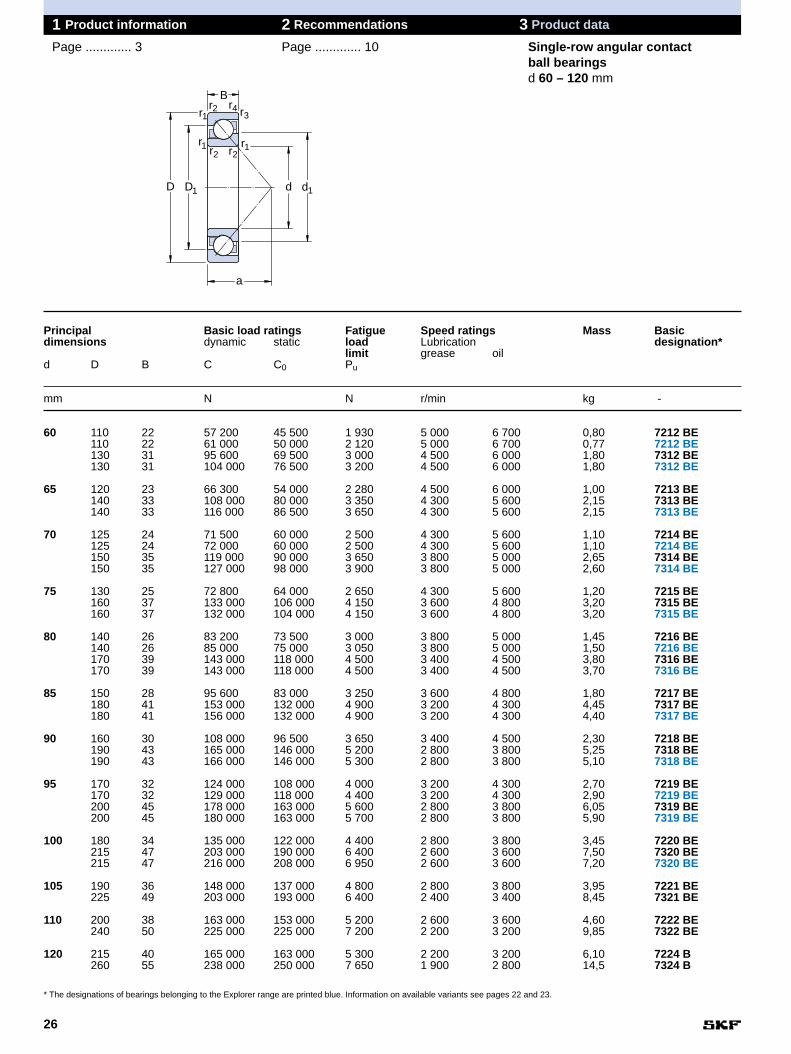
Single-row angular contactball bearingsd 10 – 55 mm
1 Product information 2 Recommendations 3 Product data
Page ............. 3 Page ............. 10
DD
B
d d
a
rr
r
rr
rr
r12
34
12
12
1 1
Principal Basic load ratings Fatigue Speed ratings Mass Basicdimensions dynamic static load Lubrication designation*
limit grease oild D B C C0 Pu
mm N N r/min kg -
10 30 9 7 020 3 350 140 19 000 28 000 0,030 7200 BE
12 32 10 7 610 3 800 160 18 000 26 000 0,036 7201 BE37 12 10 600 5 000 208 17 000 24 000 0,060 7301 BE
15 35 11 8 840 4 800 204 17 000 24 000 0,045 7202 BE42 13 13 000 6 700 280 15 000 20 000 0,080 7302 BE
17 40 12 11 100 6 100 260 15 000 20 000 0,065 7203 BE40 12 11 000 5 850 250 15 000 20 000 0,065 7203 BE47 14 15 900 8 300 355 13 000 18 000 0,11 7303 BE
20 47 14 14 000 8 300 355 12 000 17 000 0,11 7204 BE52 15 19 000 10 400 440 10 000 15 000 0,14 7304 BE52 15 19 000 10 000 425 10 000 15 000 0,14 7304 BE
25 52 15 14 800 9 300 400 10 000 15 000 0,13 7205 BE52 15 15 600 10 000 430 10 000 15 000 0,13 7205 BE62 17 26 000 15 600 655 9 000 13 000 0,23 7305 BE62 17 26 500 15 300 655 9 000 13 000 0,23 7305 BE
30 62 16 23 800 15 600 655 8 500 12 000 0,20 7206 BE62 16 24 000 15 600 655 8 500 12 000 0,20 7206 BE72 19 34 500 21 200 900 8 000 11 000 0,34 7306 BE72 19 35 500 21 200 900 8 000 11 000 0,34 7306 BE
35 72 17 30 700 20 800 880 8 000 11 000 0,28 7207 BE72 17 31 000 20 800 880 8 000 11 000 0,28 7207 BE80 21 39 000 24 500 1 040 7 500 10 000 0,45 7307 BE80 21 41 500 26 500 1 140 7 500 10 000 0,44 7307 BE
40 80 18 36 400 26 000 1 100 7 000 9 500 0,37 7208 BE80 18 36 500 26 000 1 100 7 000 9 500 0,35 7208 BE90 23 49 400 33 500 1 400 6 700 9 000 0,63 7308 BE90 23 50 000 32 500 1370 6 700 9 000 0,64 7308 BE
45 85 19 37 700 28 000 1 200 6 700 9 000 0,42 7209 BE85 19 38 000 28 500 1 220 6 700 9 000 0,42 7209 BE100 25 60 500 41 500 1 730 6 000 8 000 0,85 7309 BE100 25 61 000 40 500 1 730 6 000 8 000 0,83 7309 BE
50 90 20 39 000 30 500 1 290 6 000 8 000 0,47 7210 BE90 20 40 000 31 000 1 320 6 000 8 000 0,47 7210 BE110 27 74 100 51 000 2 200 5 300 7 000 1,10 7310 BE110 27 75 000 51 000 2 160 5 300 7 000 1,10 7310 BE
55 100 21 48 800 38 000 1 530 5 600 7 500 0,62 7211 BE120 29 85 200 60 000 2 550 4 800 6 300 1,40 7311 BE120 29 85 000 60 000 2 550 4 800 6 300 1,40 7311 BE
* The designations of bearings belonging to the Explorer range are printed blue. Information on available variants see pages 22 and 23.

25
3
1 Product information 2 Recommendations 3 Product data
Page ............. 3 Page ............. 10
daDa
ra
ra
DbDa
ra
rb
Dimensions Abutment and fillet dimensions
d d1 D1 r1,2 r3,4 a da Da Db ra rb~ ~ min min min max max max max
mm mm
10 18,2 23,1 0,6 0,3 13 14,2 25,8 27,6 0,6 0,3
12 20,2 25,1 0,6 0,3 14 16,2 27,8 29,6 0,6 0,321,7 28,3 1 0,6 16 17,6 31,4 32,6 1 0,6
15 22,7 28 0,6 0,3 16 19,2 30,8 32,6 0,6 0,325,9 32,9 1 0,6 19 20,6 36,4 37,8 1 0,6
17 25,9 31,9 0,6 0,6 18 21,2 35,8 35,8 0,6 0,626,2 31,2 0,6 0,6 18 21,2 35,8 35,8 0,6 0,628,6 36,5 1 0,6 20 22,6 41,4 42,8 1 0,6
20 30,7 37,2 1 0,6 21 25,6 41,4 42,8 1 0,632,9 41 1,1 0,6 23 27 45 47,8 1 0,633,1 41 1,1 0,6 23 27 45 47,8 1 0,6
25 35,7 42,2 1 0,6 24 30,6 46 47,8 1 0,636,1 41,5 1 0,6 24 30,6 46 47,8 1 0,639,4 48,9 1,1 0,6 27 32 55 57,8 1 0,639,6 48,3 1,1 0,6 27 32 55 57,8 1 0,6
30 42,3 50,8 1 0,6 27 35,6 56 57,8 1 0,642,6 50,1 1 0,6 27 35,6 56 57,8 1 0,646,2 57,3 1,1 0,6 31 37 65 67,8 1 0,646,5 56,6 1,1 0,6 31 37 65 67,8 1 0,6
35 49,3 59 1,1 0,6 31 42 65 67,8 1 0,649,6 58,3 1,1 0,6 31 42 65 67,8 1 0,652,4 64,2 1,5 1 35 44 71 74,4 1,5 152,7 63,5 1,5 1 35 44 71 74,4 1,5 1
40 55,9 66,3 1,1 0,6 34 47 73 75,8 1 0,656,2 65,5 1,1 0,6 34 47 73 75,8 1 0,659,4 72,4 1,5 1 39 49 81 84,4 1,5 159,7 71,6 1,5 1 39 49 81 84,4 1,5 1
45 60,5 70,9 1,1 0,6 37 52 78 80,8 1 0,660,7 70,3 1,1 0,6 37 52 78 80,8 1 0,666,3 80,7 1,5 1 43 54 91 94,4 1,5 166,5 79,9 1,5 1 43 54 91 94,4 1,5 1
50 65,5 75,9 1,1 0,6 39 57 83 85,8 1 0,665,7 75,3 1,1 0,6 39 57 83 85,8 1 0,673,5 89,7 2 1 47 61 99 104 2 173,8 88,8 2 1 47 61 99 104 2 1
55 72,4 84,1 1,5 1 43 64 91 94,4 1,5 180 97,6 2 1 51 66 109 114 2 180,3 96,6 2 1 51 66 109 114 2 1
Conversion factors:Length: 1 mm = 0,0394 in.
1 in. = 25,4 mmForce: 1 N = 0,225 lbf
1 lbf = 4,4482 NMass: 1 kg = 2,205 lb
1 lb = 0,454 kg
26
Single-row angular contactball bearingsd 60 – 120 mm
1 Product information 2 Recommendations 3 Product data
Page ............. 3 Page ............. 10
Principal Basic load ratings Fatigue Speed ratings Mass Basicdimensions dynamic static load Lubrication designation*
limit grease oild D B C C0 Pu
mm N N r/min kg -
60 110 22 57 200 45 500 1 930 5 000 6 700 0,80 7212 BE110 22 61 000 50 000 2 120 5 000 6 700 0,77 7212 BE130 31 95 600 69 500 3 000 4 500 6 000 1,80 7312 BE130 31 104 000 76 500 3 200 4 500 6 000 1,80 7312 BE
65 120 23 66 300 54 000 2 280 4 500 6 000 1,00 7213 BE140 33 108 000 80 000 3 350 4 300 5 600 2,15 7313 BE140 33 116 000 86 500 3 650 4 300 5 600 2,15 7313 BE
70 125 24 71 500 60 000 2 500 4 300 5 600 1,10 7214 BE125 24 72 000 60 000 2 500 4 300 5 600 1,10 7214 BE150 35 119 000 90 000 3 650 3 800 5 000 2,65 7314 BE150 35 127 000 98 000 3 900 3 800 5 000 2,60 7314 BE
75 130 25 72 800 64 000 2 650 4 300 5 600 1,20 7215 BE160 37 133 000 106 000 4 150 3 600 4 800 3,20 7315 BE160 37 132 000 104 000 4 150 3 600 4 800 3,20 7315 BE
80 140 26 83 200 73 500 3 000 3 800 5 000 1,45 7216 BE140 26 85 000 75 000 3 050 3 800 5 000 1,50 7216 BE170 39 143 000 118 000 4 500 3 400 4 500 3,80 7316 BE170 39 143 000 118 000 4 500 3 400 4 500 3,70 7316 BE
85 150 28 95 600 83 000 3 250 3 600 4 800 1,80 7217 BE180 41 153 000 132 000 4 900 3 200 4 300 4,45 7317 BE180 41 156 000 132 000 4 900 3 200 4 300 4,40 7317 BE
90 160 30 108 000 96 500 3 650 3 400 4 500 2,30 7218 BE190 43 165 000 146 000 5 200 2 800 3 800 5,25 7318 BE190 43 166 000 146 000 5 300 2 800 3 800 5,10 7318 BE
95 170 32 124 000 108 000 4 000 3 200 4 300 2,70 7219 BE170 32 129 000 118 000 4 400 3 200 4 300 2,90 7219 BE200 45 178 000 163 000 5 600 2 800 3 800 6,05 7319 BE200 45 180 000 163 000 5 700 2 800 3 800 5,90 7319 BE
100 180 34 135 000 122 000 4 400 2 800 3 800 3,45 7220 BE215 47 203 000 190 000 6 400 2 600 3 600 7,50 7320 BE215 47 216 000 208 000 6 950 2 600 3 600 7,20 7320 BE
105 190 36 148 000 137 000 4 800 2 800 3 800 3,95 7221 BE225 49 203 000 193 000 6 400 2 400 3 400 8,45 7321 BE
110 200 38 163 000 153 000 5 200 2 600 3 600 4,60 7222 BE240 50 225 000 225 000 7 200 2 200 3 200 9,85 7322 BE
120 215 40 165 000 163 000 5 300 2 200 3 200 6,10 7224 B260 55 238 000 250 000 7 650 1 900 2 800 14,5 7324 B
* The designations of bearings belonging to the Explorer range are printed blue. Information on available variants see pages 22 and 23.
DD
B
d d
a
rr
r
rr
rr
r12
34
12
12
1 1

27
3
1 Product information 2 Recommendations 3 Product data
Page ............. 3 Page ............. 10
Dimensions Abutment and fillet dimensions
d d1 D1 r1,2 r3,4 a da Da Db ra rb~ ~ min min min max max max max
mm mm
60 79,3 92,5 1,5 1 47 69 101 104 1,5 179,6 91,7 1,5 1 47 69 101 104 1,5 187 106 2,1 1,1 55 72 118 123 2 187,2 105 2,1 1,1 55 72 118 123 2 1
65 86,3 101 1,5 1 50 74 111 114 1,5 193,8 114 2,1 1,1 60 77 128 133 2 194,1 113 2,1 1,1 60 77 128 133 2 1
70 91,3 106 1,5 1 53 79 116 119 1,5 191,5 105 1,5 1 53 79 116 119 1,5 1100 123 2,1 1,1 64 82 138 143 2 1101 122 2,1 1,1 64 82 138 143 2 1
75 96,3 111 1,5 1 56 84 121 124 1,5 1108 130 2,1 1,1 68 87 148 153 2 1108 129 2,1 1,1 68 87 148 153 2 1
80 103 119 2 1 59 91 129 134 2 1103 118 2 1 59 91 129 134 2 1114 139 2,1 1,1 72 92 158 163 2 1115 137 2,1 1,1 72 92 158 163 2 1
85 110 128 2 1 63 96 139 144 2 1121 147 3 1,1 76 99 166 173 2,5 1122 146 3 1,1 76 99 166 173 2,5 1
90 117 136 2 1 67 101 149 154 2 1128 155 3 1,1 80 104 176 183 2,5 1129 154 3 1,1 80 104 176 183 2,5 1
95 124 144 2,1 1,1 72 107 158 163 2 1124 143 2,1 1,1 72 107 158 163 2 1135 163 3 1,1 84 109 186 193 2,5 1136 162 3 1,1 84 109 186 193 2,5 1
100 131 152 2,1 1,1 76 112 168 173 2 1144 176 3 1,1 90 114 201 208 2,5 1144 174 3 1,1 90 114 201 208 2,5 1
105 138 160 2,1 1,1 80 117 178 183 2 1151 183 3 1,1 94 119 211 218 2,5 1
110 145 169 2,1 1,1 84 122 188 193 2 1160 195 3 1,1 99 124 226 233 2,5 1
120 157 180 2,1 1,1 90 132 203 208 2 1175 210 3 1,1 107 134 246 253 2,5 1
daDa
ra
ra
DbDa
ra
rb
Conversion factors:Length: 1 mm = 0,0394 in.
1 in. = 25,4 mmForce: 1 N = 0,225 lbf
1 lbf = 4,4482 NMass: 1 kg = 2,205 lb
1 lb = 0,454 kg

28
Single-row angular contactball bearingsd 130 – 240 mm
1 Product information 2 Recommendations 3 Product data
Page ............. 3 Page ............. 10
Principal Basic load ratings Fatigue Speed ratings Mass Basicdimensions dynamic static load Lubrication designation*
limit grease oild D B C C0 Pu
mm N N r/min kg -
130 230 40 186 000 193 000 6 100 1 900 2 800 6,95 7226 B280 58 251 000 270 000 8 000 1 800 2 600 17,5 7326 B
140 250 42 182 000 196 000 5 850 1 800 2 600 8,85 7228 B300 62 276 000 310 000 8 800 1 700 2 400 21,5 7328 B
150 270 45 195 000 224 000 6 550 1 700 2 400 11,5 7230 B320 65 302 000 365 000 10 200 1 600 2 200 26,0 7330 B
160 290 48 199 000 236 000 6 700 1 600 2 200 14,0 7232 B
170 310 52 221 000 270 000 7 350 1 600 2 200 17,5 7234 B360 72 358 000 455 000 12 000 1 400 1 900 36,0 7334 B
180 320 52 251 000 320 000 8 500 1 500 2 000 18,0 7236 B380 75 371 000 490 000 12 500 1 300 1 800 42,0 7336 B
190 400 78 410 000 560 000 13 700 1 200 1 700 48,5 7338 B
200 360 58 291 000 400 000 10 000 1 300 1 800 25,0 7240 B420 80 449 000 655 000 15 600 1 100 1 600 53,0 7340 B
220 400 65 319 000 465 000 11 200 1 100 1 600 37,0 7244 B
240 440 72 364 000 540 000 12 500 1 000 1 500 49,0 7248 B
* The designations of bearings belonging to the Explorer range are printed blue. Information on available variants see pages 22 and 23.
DD
B
d d
a
rr
r
rr
rr
r12
34
12
12
1 1

29
3
1 Product information 2 Recommendations 3 Product data
Page ............. 3 Page ............. 10
Dimensions Abutment and fillet dimensions
d d1 D1 r1,2 r3,4 a da Da Db ra rb~ ~ min min min max max max max
mm mm
130 169 193 3 1,1 96 144 216 222 2,5 1189 227 4 1,5 115 147 263 271 3 1,5
140 184 208 3 1,1 103 154 236 243 2,5 1203 243 4 1,5 123 157 283 291 3 1,5
150 199 223 3 1,1 111 164 256 263 2,5 1218 258 4 1,5 131 167 303 311 3 1,5
160 211 241 3 1,1 118 174 276 283 2,5 1
170 224 258 4 1,5 127 187 293 301 3 1,5246 292 4 1,5 147 187 343 351 3 1,5
180 236 266 4 1,5 131 197 303 313 3 1,5260 308 4 2 156 197 363 369 3 2
190 275 323 5 2 164 210 380 389 4 2
200 265 297 4 1,5 146 217 343 351 3 1,5289 335 5 2 170 220 400 409 4 2
220 294 328 4 1,5 164 237 383 391 3 1,5
240 322 361 4 1,5 180 257 423 431 3 1,5
daDa
ra
ra
DbDa
ra
rb
Conversion factors:Length: 1 mm = 0,0394 in.
1 in. = 25,4 mmForce: 1 N = 0,225 lbf
1 lbf = 4,4482 NMass: 1 kg = 2,205 lb
1 lb = 0,454 kg

30
1 Product information 2 Recommendations 3 Product data
Page ............. 3 Page ............. 10 Double-row bearings
General bearing dataDesignsSKF double-row angular contact ballbearings correspond in design to twosingle-row angular contact ball bear-ings but take up less axial space (➔ fig ).
Only bearings in the 32 and 33Series are shown in this brochure.Bearings in the 52 and 53 Series (thedesignation used in the US market)have the same performance characte-ristics and dimensional features. How-ever bearings in the 52 and 53 Seriesuse a high temperature grease.
The SKF standard range of double-row angular contact ball bearings in-cludes
• bearings of basic design, suffix desig-nation A (➔ fig and )
• bearings with shields, suffix designa-tion A–2Z (➔ fig and )
• bearings with seals, suffix designa-tion A–2RS1 (➔ fig )
• separable bearings with two-pieceinner ring, suffix designation D (➔ fig )
• non-separable bearings with two-piece inner ring and snap ring, suffixdesignation DNRCBM (➔ fig )
The bearing range covers sizes from10 to 110 mm bore diameter.
For information about other double-row angular contact ball bearings,please refer to the "SKF InteractiveEngineering Catalogue" on CD-ROMor online at www.skf.com.
Basic designDouble-row angular contact ball bear-ings in the 32 A and 33 A Series havea 30 ° contact angle and are non-separable. These bearings do not con-tain filling slots and therefore canaccommodate axial loads acting in
2g
2f
2e
2d2c
2b2a
1
both directions. Many of these bear-ings are manufactured in Explorer qua-lity.
For manufacturing reasons, bearingsof the basic design may have seal re-cesses on inner and outer rings, evenif they are supplied without seals or shields (➔ fig ).
Bearings with shields or sealsSKF bearings in the 32 A and 33 ASeries are available with
• shields (non-rubbing seals) or • seals (rubbing seals)
at both sides. As standard, these bear-ings are filled with an NLGI Class 3 lithium base grease, which has goodcorrosion inhibiting properties and canbe used at temperatures between -30and +120 °C (-20 and + 250 °F).Bearings with this lithium base greasecarry the suffix MT33.
If sealed double-row bearings with ahigh-temperature grease are needed,bearings from the 52 or 53 Seriesshould be ordered. These bearings arefilled with an NGLI Class 2 mineral-oilbased grease and polyurea thickener.This grease is resistant to ageing andhas good corrosion inhibiting proper-ties. Its operating temperature range is-30 to +175 °C (-20 to +345 °F). Thetemperature is nevertheless limited to150 °C (300 °F) by the bearing rings orto 120 °C (250 °F) by the seals or inthe eventuality of polyamide cages.
Sealed bearings are lubricated forlife and are maintenance-free. Theyshould therefore not be heated above80 °C (175 °F) prior to mounting andshould not be washed.
Bearings with shieldsBearings with shields made of sheetsteel are supplied in two different de-signs depending on the bearing vari-ant. Bearings of
2b
Double-row angular contact ball bearings
1Fig
Double-row angular contact ball bearing

31
3
1 Product information 2 Recommendations 3 Product data
Page ............. 3 Page ............. 10 Double-row bearings
• standard design have shields whichform a long sealing gap with the landof the inner ring shoulder (➔ fig ).
• Explorer design are equipped withshields which overlap the recesses inthe inner ring shoulder and form ahighly efficient labyrinth seal (➔ fig ).
Bearings with sealsBearings with seals, designation suffix2RS1, have a nitrile butadiene rubber,sheet steel reinforced seal at bothsides (➔ fig ). The seal material isresistant to ageing and wear. The tem-perature limits for the seals are -40 and
3c
3b
3a
+120 °C (-40 and +250 °F). The peri-phery of the seal engages in a recessin the outer ring without deforming thering and provides good sealing at thisposition. The rubber lip seals against arecess in the inner ring shoulder, exer-ting a slight pressure on the ring.
Bearings in the 33 D SeriesSKF double-row angular contact ballbearings in the 33 D Series (➔ fig )with two-piece inner ring incorporate alarge number of large balls and havehigh load carrying capacity as a conse-quence. The bearings have a 45 ° con-tact angle and can support heavy axialloads in both directions. The bearingsare separable.
2f
Bearings in the 33 DNRCBM Series Bearings in the 33 DNRCBM Series (➔ fig ) have been designed spe-cifically to operate under the conditionspertaining in pumps, but can also beused in other applications. Their princi-pal characteristics are
• a 40 ° contact angle,• a splitt inner ring,• machined brass cages, ball centered,• higher running accuracy,• a snap ring groove and a snap ring in
the outer ring, enabling simple andspace-saving axial location in thehousing.
2g
2Fig
a b c d e f g
Shields and seals
Design alternatives of double-row angular contact ball bearings
a b c
3Fig

32
1 Product information 2 Recommendations 3 Product data
Page ............. 3 Page ............. 10 Double-row bearings
DimensionsWith the exception of the width of bear-ing 3200 A the boundary dimensions ofthe double-row angular contact ballbearings listed in the product tableconform to ISO 15:1998.
TolerancesSKF double-row bearings of
• standard design are manufactured toNormal tolerances.
• Explorer design as well as the bear-ings in the 33 DNRCBM Series aremanufactured to P6 dimensional andrunning accuracy.
The values for their tolerances corres-pond to ISO 492:1994.
ClearanceSKF double-row angular contact ballbearings in the 32 A and 33 A Seriesare available with Normal as well aswith C3 axial internal clearance asstandard; see Tables and onpages 34 and 35.
The bearings in the 33 D and 33 DNRCBM Series are only manufac-tured with the special axial internalclearance listed in Table .
The values for axial internal clear-ances given in Table are valid forbearings before mounting and underzero measuring load.
1
1
32
Speed ratingsSpeed ratings are not speed limits.The values are based on thermal equi-librium between the bearing and itssurroundings as described in theGeneral Catalogue. With appropriatemeasures, maximum permissiblespeeds above the speed ratings arepossible.
This is especially valid for SKFExplorer angular contact ball bearings,which run noticeably cooler than stan-dard design bearings. This aspect ofrunning cooler, which can have a directaffect on permissible speeds, has notbeen taken into account in the guide-line values shown in the product table.For additional information contact yourlocal SKF representative.
MisalignmentDouble-row angular contact ball bear-ings are limited in their ability to com-pensate shaft misalignment and axialdeflections. Both conditions will in-crease noise, and decrease bearingservice life.
CagesSKF double-row angular contact ballbearings are fitted with one cage perball row. The type of cage typicallydepends on bearing design and size.In some cases two different cages areavailable so that bearings with cagesappropriate to the operating conditionscan be chosen:
• Standard design bearings in the 32 Aand 33 A Series:- snap type cage of glass fibre rein-
forced polyamide 6,6, designationsuffix TN9 (➔ fig ) or
- pressed steel, snap type cage, nodesignation suffix (➔ fig )
• Explorer design bearings in the32 A and 33 A Series: - pressed steel, crown type cage, no
designation suffix (➔ fig ) or- snap type cage of glass fibre rein-
forced polyamide 6,6, designationsuffix TN9 (➔ fig )
• Bearings in the 33 D Series:- snap type cage of glass fibre rein-
forced polyamide 6,6, designationsuffix TN9 (➔ fig ) or
- pressed steel snap type cage,designation suffix J1 (➔ fig ) or
- machined brass cage, outer ringcentred, designation suffix MA (➔ fig )
• Bearings in the 33 DNRCBM Series: - machined brass cage, ball centered,
designation suffix M (➔ fig )8
7
5
4
4
6
5
4
Bore Axial internal clearance for bearings in the seriesdiameter 32 A and 33 A 33 D 33 DNRCBMd C2 Normal C3over incl. min max min max min max min max min max
mm µm
– 10 1 11 5 21 12 28 - - - -10 18 1 12 6 23 13 31 - - - -18 24 2 14 7 25 16 34 - - - -
24 30 2 15 8 27 18 37 - - - -30 40 2 16 9 29 21 40 40 60 10 3040 50 2 18 11 33 23 44 40 60 10 30
50 65 3 22 13 36 26 48 45 65 18 3865 80 3 24 15 40 30 54 45 65 18 3880 100 3 26 18 46 35 63 45 65 - -
100 110 4 30 22 53 42 73 45 65 - -
Note Double-row angular contact ballbearings with polyamide 6,6 cagescan be used at temperatures up to+120 °C (250 °F). With the excep-tion of a few oils and greases witha synthetic base oil, and lubricantscontaining a high proportion of EPadditives when used at high tem-peratures, the lubricants generallyused for rolling bearings do nothave a detrimental effect on cageproperties.
1Table
Axial internal clearance of double-row angular contact ball bearings (before mounting, and zero measuring load)

33
3
1 Product information 2 Recommendations 3 Product data
Page ............. 3 Page ............. 10 Double-row bearings
Tables and on pages 34 - 35show which cage designs are availablefor which bearing. Information on"Cage selection" can be found onpage 15. For additional informationabout cages, contact your local SKFrepresentative.
Designation suffixesThe designation suffixes which occurmost frequently with double-row angu-lar contact ball bearings, are listed andexplained below.
A Optimised internal design, no fil-ling slots.
CB Special axial internal clearanceC2 Axial internal clearance smaller
than NormalC3 Axial internal clearance greater
than NormalD Two-piece inner ringJ1 Pressed steel snap type cageM Machined brass cage, ball
centredMA Machined brass cage, outer ring
centred MT33 Lithium base grease for oper-
ating temperatures in the rangeof -30 to +120 °C (-20 to +250 °F)
NR Snap ring groove in the outsidesurface of the outer ring withsnap ring
P5 Dimensional and running accu-racy to ISO tolerance class 5
P6 Dimensional and running accu-racy to ISO tolerance class 6
P62 P6 running accuracy and C2clearance
32
4Fig 5Fig 6Fig
8Fig
Polyamide cage Snap cage of sheet steel Crown cage made of sheet steel
Machined brass cage
7FigP63 P6 running accuracy and C3clearance
TN9 Snap type cage of glass fibrereinforced polyamide 6,6
2RS1 Rubbing seal of nitrile rubberwith sheet steel reinforcement atboth sides of the bearing
2Z Pressed steel shield at bothsides of the bearing
Machined brass cage, outer ring centred

Bearings Bearings Bearingsof open design with shields with seals
Standard bearings
Explorer bearings
Bea
rin
g s
ize
32
A
32
A/C
3
32
AT
N9
32
AT
N9/
C3
32
A-2
Z/M
T33
32
A-2
Z/C
3MT
33
32
A-2
ZT
N9/
MT
33
32
A-2
ZT
N9/
C3M
T33
32
A-2
RS
1/M
T33
32
A-2
RS
1TN
9/M
T33
Bo
re d
iam
eter
mm
00
01
02
03
04
05
06
07
08
09
10
11
12
13
14
15
16
17
18
19
20
22
10
12
15
17
20
25
30
35
40
45
50
55
60
65
70
75
80
85
90
95
100
110
34
1 Product information 2 Recommendations 3 Product data
Page ............. 3 Page ............. 10 Double-row bearings
AssortmentSKF double-row angular contact ballbearings in the 32 and 33 Series(52/53 US only) are available in a largenumber of variants. The assortment forbearings in the
• 32 A Series is listed in Table• 33 A Series is listed in Table .
The dimensions and performance dataof all bearings can be found in the pro-duct table starting on page 36.
Additional variants with other internalclearance values or different cage vari-ations are available. For details, con-tact your local SKF representative.
Bearing designationsTables and also contain thebearing designations of the bearingsavailable. The matrix headings showbearing designations without the sizecode. A darker coloured square indi-cates the position for the size whereappropriate.
Example of an order designationA double-row angular contact ballbearing in the 33 A Series
• for a 40 mm shaft diameter the bear-ing size is 08,
• with shields at both sides (-2Z),• snap type cage of glass fibre rein for-
ced polyamide 6,6 (TN9),• clearance greater than Normal (C3)• Lithium base grease (MT33)
has 3308 A-2ZTN9/C3MT33 as orderdesignation. The meaning of all desig-nation suffixes is explained on page 33.
32
32
2Table
SKF standard assortmentof double-row bearings in
the 32 A Series

35
3
1 Product information 2 Recommendations 3 Product data
Page ............. 3 Page ............. 10 Double-row bearings
Bearings Bearings Bearings Bearingsof open design with shields with seals with two-piece
inner ring
Standard bearings
Explorer bearings
Bea
rin
g s
ize
33
A
33
A/C
3
33
AT
N9
33
AT
N9/
C3
33
A-2
Z/M
T33
33
A-2
Z/C
3MT
3
33
A-2
ZT
N9/
MT
33
33
A-2
ZT
N9/
C3M
T33
33
A-2
RS
1/M
T33
33
A-2
RS
1TN
9/M
T33
33
DJ1
33
DT
N9
33
DM
A
33
DN
RC
BM
Bo
re d
iam
eter
mm
00
01
02
03
04
05
06
07
08
09
10
11
12
13
14
15
16
17
18
19
20
22
10
12
15
17
20
25
30
35
40
45
50
55
60
65
70
75
80
85
90
95
100
110
3Table
SKF standard assortmentof double-row bearings inthe 33 A Series

36
A design 33 D 33 DNR
Double-row angular contactball bearingsd 10 – 65 mm
1 Product information 2 Recommendations 3 Product data
Page ............. 3 Page ............. 10
DD d da
B
rr
rr
12
12
11
Principal Basic load ratings Fatigue Speed ratings Mass Basicdimensions dynamic static load Lubrication designation*
limit grease oild D B C C0 Pu
mm N N r/min kg -
10 30 14 7 610 4 300 183 16 000 22 000 0,051 3200 A
12 32 15,9 10 100 5 600 240 15 000 20 000 0,058 3201 A
15 35 15,9 11 200 6 700 285 12 000 17 000 0,066 3202 A42 19 15 100 9 300 400 10 000 15 000 0,13 3302 A
17 40 17,5 14 300 8 800 365 10 000 15 000 0,096 3203 A47 22,2 21 600 12 700 540 9 500 14 000 0,18 3303 A
20 47 20,6 20 000 12 000 510 9 000 13 000 0,16 3204 A52 22,2 23 600 14 600 620 8 000 11 000 0,22 3304 A
25 52 20,6 21 600 14 300 600 8 000 11 000 0,18 3205 A62 25,4 32 000 20 400 865 7 500 10 000 0,35 3305 A
30 62 23,8 30 000 20 400 865 7 000 9 500 0,29 3206 A72 30,2 41 500 27 500 1 160 6 300 8 500 0,53 3306 A
35 72 27 40 000 28 000 1 180 6 000 8 000 0,44 3207 A80 34,9 52 000 35 500 1 500 5 600 7 500 0,73 3307 A80 34,9 52 700 41 500 1 760 5 600 7 500 0,82 3307 D
40 80 30,2 47 500 34 000 1 430 5 600 7 500 0,58 3208 A90 36,5 64 000 44 000 1 860 5 300 6 700 0,95 3308 A90 36,5 49 400 41 500 1 760 5 000 6 700 1,20 3308 DNR90 36,5 68 900 64 000 2 450 5 000 6 700 1,15 3308 D
45 85 30,2 51 000 39 000 1 630 5 000 6 700 0,63 3209 A100 39,7 75 000 53 000 2 240 4 800 6 300 1,40 3309 A100 39,7 61 800 52 000 2 200 4 500 6 000 1,40 3309 DNR100 39,7 79 300 69 500 3 000 4 500 6 000 1,60 3309 D
50 90 30,2 51 000 39 000 1 660 4 800 6 300 0,66 3210 A110 44,4 90 000 64 000 2 750 4 300 5 600 1,85 3310 A110 44,4 81 900 69 500 3 000 4 000 5 300 1,90 3310 DNR110 44,4 93 600 85 000 3 600 4 000 5 300 2,10 3310 D
55 100 33,3 60 000 47 500 2 000 4 300 5 600 1,05 3211 A120 49,2 112 000 81 500 3 450 3 800 5 000 2,55 3311 A120 49,2 95 600 83 000 3 550 3 800 5 000 2,50 3311 DNR120 49,2 111 000 100 000 4 300 3 600 4 800 2,75 3311 D
60 110 36,5 73 500 58 500 2 500 4 000 5 300 1,40 3212 A130 54 127 000 95 000 4 050 3 400 4 500 3,25 3312 A
65 120 38,1 80 600 73 500 3 100 3 400 4 500 1,75 3213 A140 58,7 146 000 110 000 4 550 3 200 4 300 4,10 3313 A140 58,7 138 000 122 000 5 100 3 200 4 300 4,00 3313 DNR
* The designations of bearings belonging to the Explorer range are printed blue. Information on available variants see pages 34 and 35.

37
3
1 Product information 2 Recommendations 3 Product data
Page ............. 3 Page ............. 10
da minDa
ra
ra
da max
da minDa
ra
ra
Dimensions Abutment and fillet dimensions
d d1 D1 r1,2 a da da Da ra~ ~ min min max max
mm mm
10 15,8 25 0,6 16 14,4 15,5 25,6 0,6
12 17,2 27,7 0,6 19 16,4 17 27,6 0,6
15 20,2 30,7 0,6 21 19,4 20 30,6 0,623,7 35,7 1 24 20,6 23,5 36,4 1
17 23,3 35 0,6 23 21,4 23 35,6 0,625,7 40,2 1 28 22,6 25,5 41,4 1
20 27,7 40,9 1 28 25,6 27,5 41,4 129,9 44 1,1 30 27 29,5 45 1
25 32,7 45,9 1 30 30,6 32,5 46,4 135,7 53,4 1,1 36 32 35,5 55 1
30 38,7 55,2 1 36 35,6 38,5 56,4 139,8 64,1 1,1 42 37 39,5 65 1
35 45,4 63,9 1,1 42 42 45 65 144,6 70,5 1,5 47 43,5 44,5 71 1,552,8 71,5 1,5 76 44 - 71 1,5
40 47,8 72,1 1,1 46 47 47,5 73 150,8 80,5 1,5 53 48,5 50,5 81 1,560,1 79,5 1,5 71 49 - 81 1,559,4 80,3 1,5 84 49 - 81 1,5
45 52,8 77,1 1,1 49 52 52,5 78 155,6 90 1,5 58 54 55,5 91 1,566,9 88,4 1,5 79 54 - 91 1,566,6 88,6 1,5 93 54 - 91 1,5
50 57,8 82,1 1,1 52 56,5 57,5 83 162 99,5 2 65 60,5 61,5 99 273,5 98,3 2 88 61 - 99 273 97,2 2 102 61 - 99 2
55 63,2 92,3 1,5 57 63 63 91 1,568,4 109 2 73 66 68 109 280,5 108 2 97 66 - 109 281,3 108 2 114 66 - 109 2
60 68,8 101 1,5 63 69 68,5 101 1,573,4 118 2,1 78 72 73 118 2
65 76,3 113 1,5 69 74 76 111 1,578,5 130 2,1 84 77 78 128 294 127 2,1 114 77 - 128 2
Conversion factors:Length: 1 mm = 0,0394 in.
1 in. = 25,4 mmForce: 1 N = 0,225 lbf
1 lbf = 4,4482 NMass: 1 kg = 2,205 lb
1 lb = 0,454 kg

38
Double-row angular contactball bearingsd 70 – 110 mm
1 Product information 2 Recommendations 3 Product data
Page ............. 3 Page ............. 10
Principal Basic load ratings Fatigue Speed ratings Mass Basicdimensions dynamic static load Lubrication designation*
limit grease oild D B C C0 Pu
mm N N r/min kg -
70 125 39,7 88 400 80 000 3 400 3 200 4 300 1,90 3214 A150 63,5 153 000 125 000 5 000 3 000 4 000 5,05 3314 A
75 130 41,3 95 800 88 000 3 750 3 200 4 300 2,10 3215 A160 68,3 176 000 140 000 5 500 2 800 3 800 5,60 3315 A
80 140 44,4 106 000 95 000 3 900 3 000 4 000 2,65 3216 A170 68,3 182 000 156 000 6 000 2 400 3 400 6,80 3316 A
85 150 49,2 124 000 110 000 4 400 2 600 3 600 3,40 3217 A180 73 195 000 176 000 6 550 2 200 3 200 8,30 3317 A
90 160 52,4 130 000 120 000 4 550 2 400 3 400 4,15 3218 A190 73 195 000 180 000 6 400 2 000 3 000 9,00 3318 A
95 170 55,6 152 000 146 000 5 400 2 200 3 200 5.00 3219 A200 77,8 225 000 216 000 7 500 1 900 2 800 11,00 3319 A
100 180 60,3 178 000 166 000 6 000 2 000 3 000 6,10 3220 A215 82,6 255 000 255 000 8 650 1 800 2 600 13,50 3320 A
110 200 69,8 212 000 212 000 7 200 1 900 2 800 8,80 3222 A240 92,1 291 000 305 000 9 800 1 700 2 400 19,00 3322 A
* The designations of bearings belonging to the Explorer range are printed blue. Information on available variants see pages 34 and 35.
DD d da
B
rr
rr
12
12
11

39
3
1 Product information 2 Recommendations 3 Product data
Page ............. 3 Page ............. 10
Dimensions Abutment and filletdimensions
d d1 D1 r1,2 a da Da ra~ ~ min min max
mm mm
70 82 118 1,5 74 79 116 1,594,8 124 2,1 91 82 138 2
75 84,6 123 1,5 77 84 121 1,5103 135 2,1 96 87 148 2
80 97,7 120 2 82 91 129 2108 141 2,1 101 92 158 2
85 104 128 2 88 96 139 2115 153 3 110 99 166 2,5
90 111 139 2 94 101 149 2123 160 3 114 104 176 2,5
95 119 147 2,1 101 107 158 2127 168 3 118 109 186 2,5
100 126 155 2,1 107 112 168 2136 180 3 127 114 201 2,5
110 139 172 2,1 119 122 188 2153 200 3 142 124 226 2,5
da minDa
ra
ra
Conversion factors:Length: 1 mm = 0,0394 in.
1 in. = 25,4 mmForce: 1 N = 0,225 lbf
1 lbf = 4,4482 NMass: 1 kg = 2,205 lb
1 lb = 0,454 kg

40
Precision angular contact ball bearingsSKF manufactures high-precisionangular contact ball bearings for themachine tool industry. These radialangular contact ball bearings are avail-able as series 719, 70 and 72 with twodifferent contact angles. For additionalinformation please ask for our catalo-gue “High-precision bearings“.
Four-point contact ballbearingsFour-point contact ball bearings aresingle row angular contact ball bear-ings having raceways that are sodesigned that the bearings can supportaxial loads acting in both directions.They take up less space axially thandouble-row bearings.
They are designed to accommodateloads, which are predominantly axialand in many applications they are usedas thrust bearings together withcylindrical roller bearings that take theradial loads. For additional informationon these bearings, consult the "SKFGeneral Catalogue" or the "SKF Inter-active Engineering Catalogue" on CD-ROM or online at www.skf.com.
Hybrid bearingsAngular ball bearings are also manu-factured as hybrid bearings. Thesebearings combine steel rings with cera-mic balls. They are typically used inapplications where there is inadequatelubrication, excessive amounts of con-tamination or stray electrical currents.Even under poor lubrication conditionsthere is no metal-to-metal contact be-tween the raceways and balls becauseof the ceramic material.
Hybrid bearings can attain a servicelife 3 to 30 times longer than a compar-able all-steel bearing.
Angular contact thrustball bearingsHigh axial stability is important forbearings in roller or precision ball screws. The manufacturing quality ofSKF angular contact thrust ball bear-ings, their running accuracy and lowfriction contribute to their outstandingpositioning accuracy of machine toolspindles or ball screws. You can findadditional information in the SKF cata-logue "High-precision bearings".
Other SKF angular contact ball bearings

41
3
Electrically-insulatedbearingsTo insulate bearings in electrical drivesfrom stray currents, SKF INSOCOAT®
bearings can be used. Available onlyfrom SKF, this ceramic coating is ap-plied to the outer or inner ring of bear-ings used in electric applications. Foradditional information on SKF INSO-COAT® bearings, contact your localSKF representative. You can also findmore information in our publication5225.
NoWear® bearingsNoWear bearings consist of steel ringsand rolling elements, but the rollingelements and, if necessary, the race-ways are coated with a diamond-like
carbon. NoWear bearings are typicallyused in applications where there arespecial operating conditions like highspeeds with low loads, poor lubricationor high levels of contamination. Foradditional information about NoWearbearings, see publication 5047.
Application-specificbearing unitsSKF manufactures optimised angularcontact ball bearing units for specialapplications. They can be, for examp-le, double-row units with different con-tact angles or units with flanges forquick installation, sealed and lubrica-ted for life. For application-specificunits, please contact your SKF repre-sentative.
Special designs for theautomobile industryAngular contact ball bearings can beadapted easily to new applications.The automobile industry uses this cha-racteristic to its advantage in clutches,motors, drives, steering assembliesand hub units.
SKF manufactures complete hubunits in a large variety of designs.Clutch release bearings and wire raceball bearings for steering columns alsobelong to our programme.

42
The SKF Group– a worldwide corporation
SKF is an international industrial Groupoperating in some 130 countries and isworld leader in bearings.
The company was founded in 1907following the invention of the self-align-ing ball bearing by Sven Wingquist and,after only a few years, SKF began toexpand all over the world.
Today, SKF has some 40 000 em-ployees and around 80 manufacturingfacilities spread throughout the world.An international sales network includesa large number of sales companies andsome 7 000 distributors and retailers.Worldwide availability of SKF productsis supported by a comprehensivetechnical advisory service.
The key to success has been a con-sistent emphasis on maintaining thehighest quality of its products and services. Continuous investment inresearch and development has also
played a vital role, resulting in manyexamples of epoch-making innovations.
The business of the Group consistsof bearings, seals, special steel and acomprehensive range of other high-tech industrial components. Theexperience gained in these variousfields provides SKF with the essentialknowledge and expertise required inorder to provide the customers with themost advanced engineering productsand efficient service.

43
The SKF Group is the first major bearingmanufacturer to have been granted approv-al according to ISO 14001, the internationalstandard for environmental managementsystems. The certificate is the most com-prehensive of its kind and covers more than60 SKF production units in 17 countries. The SKF Engineering & Research Centre
is situated just outside Utrecht in TheNetherlands. In an area of 17,000 squaremetres (185,000 sq.ft) some 150 scientists,engineers and support staff are engaged inthe further improvement of bearing perform-ance. They are developing technologiesaimed at achieving better materials, betterdesigns, better lubricants and better seals –together leading to an even better under-standing of the operation of a bearing in itsapplication. This is also where the SKF LifeTheory was evolved, enabling the design ofbearings which are even more compact andoffer even longer operational life.
SKF has developed the Channel concept infactories all over the world. This drasticallyreduces the lead-time from raw material toend product as well as work in progressand finished goods in stock. The conceptenables faster and smoother informationflow, eliminates bottlenecks and bypassesunnecessary steps in production. TheChannel team members have the know-ledge and commitment needed to share theresponsibility for fulfilling objectives in areassuch as quality, delivery time, productionflow etc.
SKF manufactures ball bearings, roller bearings and plain bearings. The smallestare just a few millimetres (a fraction of aninch) in diameter, the largest several metres.SKF also manufactures oil and bearingseals which prevent dirt from entering andlubricant from leaking out. SKF's sub-sidiaries CR and RFT S.p.A. are among theworld's largest producers of seals.

® SKF, INSOCOAT and NoWear are registe-red trademarks of SKF AB, Sweden
TM Total Shaft Solutions and Asset EfficiencyOptimization are trademarks of SKF AB,Sweden
© Copyright SKF 2002The contents of this publication are thecopyright of the publisher and may not bereproduced (even extracts) unless permis-sion is granted. Every care has been takento ensure the accuracy of the informationcontained in this publication but no liabilitycan be accepted for any loss or damagewhether direct, indirect or consequentialarising out of the use of the information con-tained herein.
Publication 5105 E
www.skf.com
s®