rolling bearings - svetraders.comsvetraders.com/documents/skf/needlerollerbearings.pdf · 6 needle...
TRANSCRIPT
Rolling bearings

6 Needle roller bearings
Designs and variants . . . . . . . . . . . . . . 674Needle roller and cage assemblies . . . . 674
Basic design bearings . . . . . . . . . . . . . 675Other needle roller and cage assemblies . . . . . . . . . . . . . . . . . . . . . 675
Drawn cup needle roller bearings . . . . . 677with open ends . . . . . . . . . . . . . . . . . . 678with a closed end . . . . . . . . . . . . . . . . 678full complement . . . . . . . . . . . . . . . . . 678Arrangements with components and other bearings . . . . . . . . . . . . . . . . . . 679
Needle roller bearings with machined rings . . . . . . . . . . . . . . . . . . . . . . . . . . . . 680
with flanges . . . . . . . . . . . . . . . . . . . . 681without flanges . . . . . . . . . . . . . . . . . . 682Arrangements with other bearings . . 682
Alignment needle roller bearings . . . . . . 683Combined needle roller bearings . . . . . . 683
Needle roller / angular contact ball bearings . . . . . . . 684thrust ball bearings . . . . . . . . . . . . . . 685cylindrical roller thrust bearings . . . . 689
Needle roller bearing components. . . . . 691Needle roller bearing inner rings . . . . 691Needle rollers . . . . . . . . . . . . . . . . . . . 692
Cages . . . . . . . . . . . . . . . . . . . . . . . . . . . . 693Sealing solutions . . . . . . . . . . . . . . . . . . 696
Greases for capped bearings . . . . . . . 698Relubrication facilities . . . . . . . . . . . . . . 699
Bearing data . . . . . . . . . . . . . . . . . . . . . 701(Dimension standards, tolerances, operating clearance, internal clearance, misalignment)
Loads . . . . . . . . . . . . . . . . . . . . . . . . . . . 711(Minimum load, equivalent loads, safety load factor)
Temperature limits . . . . . . . . . . . . . . . . 714
Permissible speed . . . . . . . . . . . . . . . . . 714
Design of bearing arrangements . . . . 714Abutment dimensions . . . . . . . . . . . . . . 714Shaft and housing tolerances . . . . . . . . 716Mounting . . . . . . . . . . . . . . . . . . . . . . . . . 718
Designation system . . . . . . . . . . . . . . . 720
Product tables6.1 Needle roller and cage assemblies 7226.2 Drawn cup needle roller bearings 730
Needle roller bearings with machined rings6.3 with flanges, without an
inner ring . . . . . . . . . . . . . . . . . . . . 7446.4 with flanges, with an inner ring . . 7586.5 without flanges, without an
inner ring . . . . . . . . . . . . . . . . . . . . 7706.6 without flanges, with an
inner ring . . . . . . . . . . . . . . . . . . . . 774
Alignment needle roller bearings6.7 without an inner ring . . . . . . . . . . 7766.8 with an inner ring . . . . . . . . . . . . . 778
6.9 Needle roller / angular contact ball bearings . . . . . . . . . . . . . . . . . 780
6.10 Needle roller / thrust ball bearings, full complement thrust bearing . . 784
6.11 Needle roller / thrust ball bearings, thrust bearing with a cage . . . . . . 786
6.12 Needle roller / cylindrical roller thrust bearings . . . . . . . . . . . . . . . 788
6.13 Needle roller bearing inner rings . 7906.14 Needle rollers . . . . . . . . . . . . . . . . 794
Other needle roller bearingsBearings with Solid Oil . . . . . . . . . . . . . . 1185NoWear coated bearings . . . . . . . . . . . . 1241Universal joint bearings . .† skf.com/bearings
673
6 Needle roller bearings
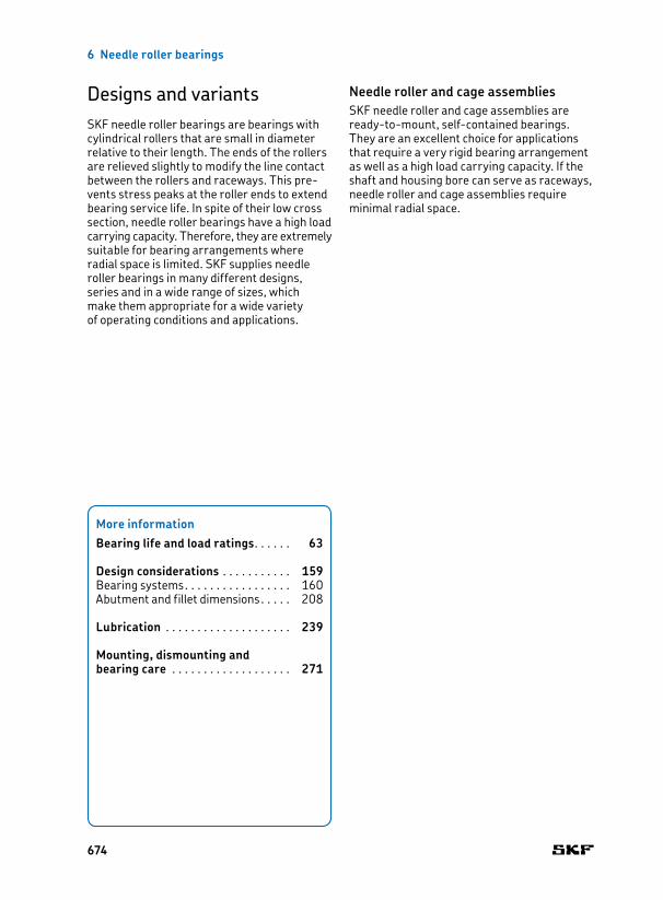
Designs and variantsSKF needle roller bearings are bearings with cylindrical rollers that are small in diameter relative to their length. The ends of the rollers are relieved slightly to modify the line contact between the rollers and raceways. This prevents stress peaks at the roller ends to extend bearing service life. In spite of their low cross section, needle roller bearings have a high load carrying capacity. Therefore, they are extremely suitable for bearing arrangements where radial space is limited. SKF supplies needle roller bearings in many different designs, series and in a wide range of sizes, which make them appropriate for a wide variety of operating conditions and applications.
Needle roller and cage assemblies SKF needle roller and cage assemblies are readytomount, selfcontained bearings. They are an excellent choice for applications that require a very rigid bearing arrangement as well as a high load carrying capacity. If the shaft and housing bore can serve as raceways, needle roller and cage assemblies require minimal radial space.
More information
Bearing life and load ratings . . . . . . 63
Design considerations . . . . . . . . . . . 159Bearing systems . . . . . . . . . . . . . . . . . 160Abutment and fillet dimensions . . . . . 208
Lubrication . . . . . . . . . . . . . . . . . . . . 239
Mounting, dismounting and bearing care . . . . . . . . . . . . . . . . . . . 271
674

6
Designs and variants
Basic design bearingsSKF basic design needle roller and cage assemblies are identified by the series designation K and available in single row (no designation suffix) and double row (designation suffix ZW) designs († fig. 1). They are characterized by the following properties:
• simple and rugged design• accurate roller guidance in the cage pockets• good running performance
Other needle roller and cage assembliesOn request, SKF also supplies needle roller and cage assemblies in other sizes or different designs.
Needle roller and cage assemblies with a split cage can be used where raceways are recessed in the shaft († fig. 2).
Fig. 2
Fig. 1
K .. ZW
K
675
6 Needle roller bearings
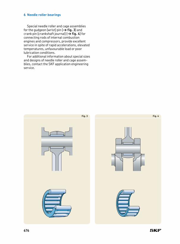
Special needle roller and cage assemblies for the gudgeon (wrist) pin († fig. 3) and crank pin (crankshaft journal) († fig. 4) for connecting rods of internal combustion engines and compressors, provide excellent service in spite of rapid accelerations, elevated temperatures, unfavourable load or poor lubrication conditions.
For additional information about special sizes and designs of needle roller and cage assemblies, contact the SKF application engineering service.
Fig. 3 Fig. 4
676

6
Designs and variants
Fig. 5
HK
Fig. 6
BK
Fig. 7
HN
Drawn cup needle roller bearingsSKF drawn cup needle roller bearings have a deep drawn, thinwalled outer ring. They are characterized by a very low sectional height and high load carrying capacity. Drawn cup needle roller bearings are typically used in applications where the housing bore cannot be used as a raceway for a needle roller and cage assembly, but where a very compact and economical bearing arrangement is required. These bearings are mounted with a tight interference fit in the housing. That enables a simple and economic design of the housing bore, as shoulders or snap rings are not required to locate the bearing axially.
The drawn cup of hardened steel and the needle roller and cage assembly of these bearings form a nonseparable unit.
SKF supplies a wide assortment of drawn cup needle roller bearings. This includes:
• drawn cup needle roller bearings with open ends († fig. 5)• drawn cup needle roller bearings with a
closed end († fig. 6)• full complement drawn cup needle roller
bearings with open ends († fig. 7)
677

6 Needle roller bearings
SKF supplies all drawn cup needle roller bearings without an inner ring. These bearings are generally designed with one needle roller and cage assembly. However, wide sizes incorp orate two needle roller and cage assemblies immediately adjacent to each other, with a lubrication hole in the outer ring († fig. 8). The double row bearings are not identified by any designation suffix but are marked in the product tables by a footnote.
Drawn cup needle roller bearings with open endsSKF drawn cup needle roller bearings with open ends († fig. 5, page 677) are identified by the series designation HK. They are available open (without seals) or sealed on one or both sides († Sealing solutions, page 696).
Drawn cup needle roller bearings with a closed endSKF drawn cup needle roller bearings with a closed end († fig. 6, page 677) are identified by the series designation BK. They are available open or sealed († Sealing solutions, page 696) and are suitable for bearing arrangements at the end of a shaft. The profiled design of the closed end accommodates small axial guidance forces.
Full complement drawn cup needle roller bearingsSKF full complement drawn cup needle roller bearings († fig. 7, page 677) are identified by the series designation HN. They are suitable for very heavy radial loads at moderate speeds and are available with open ends and without seals only.
Fig. 8
HK (double row)
678
6
Designs and variants
Greases for full complement drawn cup bearingsFull complement drawn cup needle roller bearings are supplied with a special grease to secure the rollers during transport. However, SKF recommends relubricating after mounting, as this grease does not provide sufficient long term lubrication. Depending on the required consistency class, SKF recommends SKF LGEP 2 or SKF LGMW 1 grease for relubrication. The technical specifications of the initial grease fill and the relubrication greases are listed in table 1.
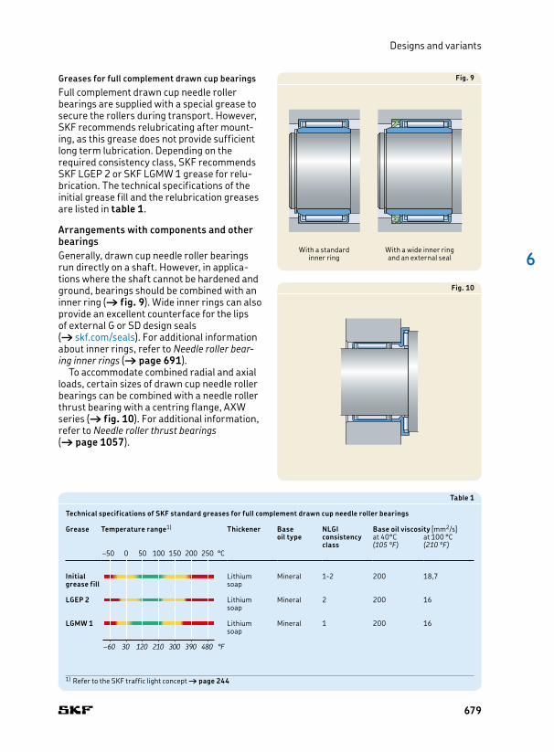
Arrangements with components and other bearingsGenerally, drawn cup needle roller bearings run directly on a shaft. However, in applications where the shaft cannot be hardened and ground, bearings should be combined with an inner ring († fig. 9). Wide inner rings can also provide an excellent counterface for the lips of external G or SD design seals († skf.com/seals). For additional information about inner rings, refer to Needle roller bear-ing inner rings († page 691).
To accommodate combined radial and axial loads, certain sizes of drawn cup needle roller bearings can be combined with a needle roller thrust bearing with a centring flange, AXW series († fig. 10). For additional information, refer to Needle roller thrust bearings († page 1057).
Fig. 10
Fig. 9
With a standard inner ring
With a wide inner ring and an external seal
Table 1
Technical specifications of SKF standard greases for full complement drawn cup needle roller bearings
Grease
Temperature range1)
Thickener
Base oil type
NLGI consistencyclass
Base oil viscosity [mm2/s]at 40°C at 100 °C(105 °F) (210 °F)
Initial grease fill
Lithium soap
Mineral 12 200 18,7
LGEP 2 Lithium soap
Mineral 2 200 16
LGMW 1 Lithium soap
Mineral 1 200 16
1) Refer to the SKF traffic light concept † page 244
–50 0 50 100 150 200 250 °C
–60 30 120 210 300 390 480 °F
–50 0 50 100 150 200 250 °C
–60 30 120 210 300 390 480 °F
679
6 Needle roller bearings
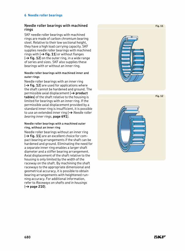
Needle roller bearings with machined ringsSKF needle roller bearings with machined rings are made of carbon chromium bearing steel. Relative to their low sectional height, they have a high load carrying capacity. SKF supplies needle roller bearings with machined rings with († fig. 11) or without flanges († fig. 12) on the outer ring, in a wide range of series and sizes. SKF also supplies these bearings with or without an inner ring.
Needle roller bearings with machined inner and outer ringsNeedle roller bearings with an inner ring († fig. 12) are used for applications where the shaft cannot be hardened and ground. The permissible axial displacement († product tables) of the shaft relative to the housing is limited for bearings with an inner ring. If the permissible axial displacement provided by a standard inner ring is insufficient, it is possible to use an extended inner ring († Needle roller bearing inner rings, page 691).
Needle roller bearings with a machined outer ring, without an inner ringNeedle roller bearings without an inner ring († fig. 11) are an excellent choice for compact bearing arrangements if the shaft can be hardened and ground. Eliminating the need for a separate inner ring enables a larger shaft diameter and a stiffer bearing arrangement. Axial displacement of the shaft relative to the housing is only limited by the width of the raceway on the shaft. By machining the shaft raceways to the appropriate dimensional and geometrical accuracy, it is possible to obtain bearing arrangements with heightened running accuracy. For additional information, refer to Raceways on shafts and in housings († page 210).
Fig. 11
Fig. 12
680
6
Designs and variants
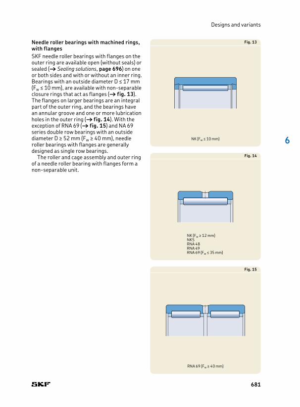
Needle roller bearings with machined rings, with flanges SKF needle roller bearings with flanges on the outer ring are available open (without seals) or sealed († Sealing solutions, page 696) on one or both sides and with or without an inner ring. Bearings with an outside diameter D ≤ 17 mm (Fw ≤ 10 mm), are available with nonseparable closure rings that act as flanges († fig. 13). The flanges on larger bearings are an integral part of the outer ring, and the bearings have an annular groove and one or more lubrication holes in the outer ring († fig. 14). With the exception of RNA 69 († fig. 15) and NA 69 series double row bearings with an outside diameter D ≥ 52 mm (Fw ≥ 40 mm), needle roller bearings with flanges are generally designed as single row bearings.
The roller and cage assembly and outer ring of a needle roller bearing with flanges form a nonseparable unit.
Fig. 15
RNA 69 (Fw ≥ 40 mm)
Fig. 14
NK (Fw ≥ 12 mm)NKSRNA 48RNA 49RNA 69 (Fw ≤ 35 mm)
Fig. 13
NK (Fw ≤ 10 mm)
681

6 Needle roller bearings
Needle roller bearings with machined rings, without flangesSKF needle roller bearings without flanges on the outer ring are separable, i.e. the outer ring, needle roller and cage assembly and inner ring, can all be mount ed separately. Therefore, the needle roller and cage assembly can either be mount ed together with the outer ring or with the shaft or inner ring, depending on the arrangement design. It can also be inserted between the outer ring and shaft or inner ring as the final step. However, needle roller and cage assemblies and bearing outer rings must always be kept together as supplied.
SKF needle roller bearings without flanges are generally designed with one needle roller and cage assembly († fig. 12, page 680). However, wide sizes incorporate two needle roller and cage assemblies immediately adjacent to each other and have an annular groove and a lubrication hole in the outer ring († fig. 16). The double row bearings are not identified by any designation suffix, but are marked in the product tables by a footnote.
Arrangements with other bearingsTo accommodate combined radial and axial loads, needle roller bearings with machined rings can be combined with a needle roller thrust bearing with a centring flange, AXW series, if the outside diameter D of the radial bearing is equal to the flange diameter D1 of the thrust bearing († fig. 17). For additional information, refer to Needle roller thrust bear-ings († page 1057).
Fig. 16
RNAO
Fig. 17
Without an inner ring
With an inner ring
682
6
Designs and variants
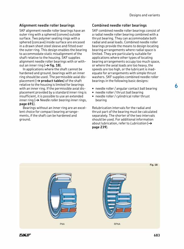
Alignment needle roller bearingsSKF alignment needle roller bearings have an outer ring with a sphered (convex) outside surface. Two polymer seating rings with a sphered (concave) inside surface are encased in a drawn sheet steel sleeve and fitted over the outer ring. This design enables the bearing to ac com mo date static misalignment of the shaft relative to the housing. SKF supplies alignment needle roller bearings with or without an inner ring († fig. 18).
In applications where the shaft cannot be hardened and ground, bearings with an inner ring should be used. The permissible axial displacement († product tables) of the shaft relative to the housing is limited for bearings with an inner ring. If the permissible axial displacement provided by a standard inner ring is insufficient, it is possible to use an extended inner ring († Needle roller bearing inner rings, page 691).
Bearings without an inner ring are an excellent choice for compact bearing arrangements, if the shaft can be hardened and ground.
Combined needle roller bearingsSKF combined needle roller bearings consist of a radial needle roller bearing combined with a thrust bearing. They can accommodate both radial and axial loads. Combined needle roller bearings provide the means to design locating bearing arrangements where radial space is limited. They are particularly suitable for applications where other types of locating bearing arrangements occupy too much space, or where the axial loads are too heavy, the speeds are too high, or the lubricant is inadequate for arrangements with simple thrust washers. SKF supplies combined needle roller bearings in the following basic designs:
• needle roller / angular contact ball bearing• needle roller / thrust ball bearing• needle roller / cylindrical roller thrust
bearing
Relubrication intervals for the radial and thrust part of the bearing must be calculated separately. The shorter of the two intervals should be used. For additional information about lubrication, refer to Lubrication († page 239).
Fig. 18
PNA RPNA
683

6 Needle roller bearings
Needle roller / angular contact ball bearingsSKF needle roller / angular contact ball bearings combine a radial needle roller bearing with an angular contact ball bearing. The radial loads are accommodated exclusively by the needle roller bearing and the axial loads exclusively by the angular contact ball bearing. These low cross section bearings can operate at high speeds and accommodate heavy radial and light axial loads. SKF supplies these bearings without seals in the following two series:
• NKIA series († fig. 19), bearings can accommodate axial loads in one direction • NKIB series († fig. 20), bearings can
accommodate axial loads in both directions
Bearings in both series are separable i.e. the inner ring can be mounted separately from the outer ring, rolling element and cage assemblies. However, the inner rings in the NKIB series are not interchangeable with those from another seemingly identical bearing. Therefore, the bearings must be kept together as supplied.
Depending on the application, needle roller / angular contact ball bearings can be grease or oil lubricated. In the case of grease lubrication, both the needle roller and angular contact ball bearing should be filled with the same lubricant prior to mounting.
Fig. 19
NKIA 59
Fig. 20
NKIB 59
Fig. 21
NKIA 59, backtoback arrangement
684

6
Designs and variants
NKIA seriesNeedle roller / angular contact ball bearings in the NKIA 59 series († fig. 19) can accommodate axial loads in one direction and can, therefore, locate the shaft in one direction only. For short shafts and where changes in length as a result of thermal expansion are relatively minor, two bearings in the NKIA 59 series can be mounted backtoback († fig. 21).
NKIB seriesNeedle roller / angular contact ball bearings in the NKIB 59 series († fig. 20) can locate a shaft in both directions. The axial clearance is between 0,08 and 0,25 mm. To facilitate mounting, the bearing has a twopiece inner ring. When mounting the inner ring, it is important that the two pieces are mounted immediately adjacent to each other without any gap between them.
Fig. 22
NX
Fig. 23
NKX
Needle roller / thrust ball bearingsSKF needle roller / thrust ball bearings combine a radial needle roller bearing and a thrust ball bearing. SKF supplies these bearings in the following two series:
• NX series († fig. 22), with a full complement thrust ball bearing• NKX series († fig. 23), with a thrust ball
bearing with a cage
685

6 Needle roller bearings
SKF supplies the bearings of both series without an inner ring. In applications where the shaft cannot be hardened and ground, the needle roller bearing can be combined with an inner ring († fig. 24). Appropriate inner rings are listed in the product tables and must be ordered separately.
Needle roller / thrust ball bearings can accommodate axial loads in one direction and can, therefore, locate the shaft in one direction only. For short shafts and where changes in length as a result of thermal expansion are relatively minor, two bearings can be mounted backtoback († fig. 25). For these types of arrangements, SKF recommends elastically preloading the thrust ball bearings with cup springs (Belleville washers). This elastic preload helps to prevent the balls from skidding if one of the thrust bearings becomes unloaded. Preload also improves performance of the thrust ball bearings while reducing noise levels.
Fig. 25
NKX, backtoback arrangement, incorporating Belleville washers
Fig. 24
NX with an inner ring
686

6
Designs and variants
NX seriesNeedle roller / full complement thrust ball bearings in the NX series († fig. 26) are suitable for applications where there are moderate radial loads and lighter, single direction axial loads. Their extremely low sectional height enables shaft centrelines to be positioned close together like for multispindle drills. For axial support, the bearings can be mounted with a snap ring or against a shoulder in the housing bore. The snap ring groove in the outer ring provides a costeffective and axially spacesaving solution († fig. 27). The appropriate snap rings are listed in the product tables.
Needle roller / thrust ball bearings in the NX series have a stamped steel cover. It extends over the shaft washer of the thrust ball bearing and is firmly attached to the radial needle roller bearing. The cover makes these bearings nonseparable. Most often they are oil lubricated, as the cover has lubrication holes. Therefore, SKF supplies these bearings without grease.
Needle roller / thrust ball bearings in the NX series with the designation suffix Z († fig. 28) have a stamped steel cover without lubrication holes and should be grease lubricated.
Fig. 26
NX
Fig. 28
NX .. Z
Fig. 27
NX mounted with a snap ring
687

6 Needle roller bearings
NKX seriesNeedle roller / thrust ball bearings in the NKX series combine a radial needle roller bearing and a thrust ball bearing with a ball and cage thrust assembly identical to the 511 series. They permit relatively highspeed operation. The outer ring flange locates the bearings axially in one direction.
Needle roller / thrust ball bearings in the NKX series († fig. 29) do not have a cover over the thrust ball bearing. Therefore, both the ball and cage assembly and shaft washer can be mounted separately from the rest of the bearing. These bearings, without the designation suffix Z, should be oil lubricated whenever possible, as there is no cover that retains the grease in the bearing.
Needle roller / thrust ball bearings in the NKX series with the designation suffix Z († fig. 30) have a stamped steel cover without lubrication holes. The steel cover extends over the shaft washer of the thrust ball bearing. It is firmly attached to the housing washer that is integral to the needle roller bearing outer ring. The cover makes these bearings nonseparable.
Fig. 29
NKX
Fig. 30
NKX .. Z
688

6
Designs and variants
Fig. 32
Fig. 31
NKXR
Fig. 33
NKXR .. Z
Needle roller / cylindrical roller thrust bearingsSKF needle roller / cylindrical roller thrust bearings in the NKXR series († fig. 31) combine a radial needle roller bearing and a cylindrical roller thrust bearing. The cylindrical roller and cage thrust assembly is identical to the 811 series. These combined bearings are supplied without an inner ring. In applications where the shaft cannot be hardened and ground, bearings can be combined with an inner ring († fig. 32). Appropriate inner rings are listed in the product tables and must be ordered separately.
Needle roller / cylindrical roller thrust bearings in the NKXR series are separable. Both the cylindrical roller and cage thrust assembly and shaft washer can be mounted separately from the rest of the bearing. These bearings, without the designation suffix Z, should be oil lubricated whenever possible, as oil facilitates an adequate supply of lubricant to the bearing.
Needle roller / cylindrical roller thrust bearings with the designation suffix Z († fig. 33) have a stamped steel cover without lubrication holes. The steel cover extends over the shaft washer of the cylindrical roller thrust bearing. It is firmly attached to the housing washer that is integral to the needle roller bearing outer ring. The cover makes these bearings nonseparable.
689

6 Needle roller bearings
Fig. 34
NKXR, backtoback arrangement, incorporating Belleville washers
Needle roller / cylindrical roller thrust bearings can accommodate axial loads in one direction and can, therefore, locate the shaft in one direction only. For short shafts and where changes in length as a result of thermal expansion are relatively minor, two bearings can be mounted backtoback († fig. 34). For these types of arrangements, SKF recommends elastically preloading the roller thrust bearings with cup springs (Belleville washers). This elastic preload helps to prevent the rollers from skidding if one of the thrust bearings becomes unloaded. Preload also improves the performance of the bearings while reducing noise levels.
690

6
Designs and variants
Needle roller bearing components
Needle roller bearing inner ringsSKF supplies inner rings for needle roller bearings separately. They are typically combined with needle roller and cage assemblies or drawn cup needle roller bearings in applications where the shaft cannot be hardened and ground. Inner rings are available in the following two series:
• IR series († fig. 35), with or without a lubrication hole, with or without a machining allowance• LR series († fig. 36)
Inner rings in both series are also available in different widths. Wide inner rings permit greater axial displacement of the shaft, relative to the housing, when compared to standard width inner rings. They also provide an excellent counterface for the lips of contact seals († fig. 9, page 679).
Regardless of whether the ring has an interference or loose fit, it should be located on both sides to prevent axial movement. One side can be located against a shoulder. The other side can be located by either a snap ring, a distance ring or a nut.
IR seriesIR series inner rings, († fig. 35) the standard SKF inner rings for needle roller bearings, are made of carbon chromium bearing steel. The rings are hardened and ground. The raceway surface is precision ground, and has a leadin chamfer on both sides. The chamfers facilitate assembly and protect the seal lips from damage during the mounting process.
Fig. 35
Fig. 36
IR
LR
691
6 Needle roller bearings
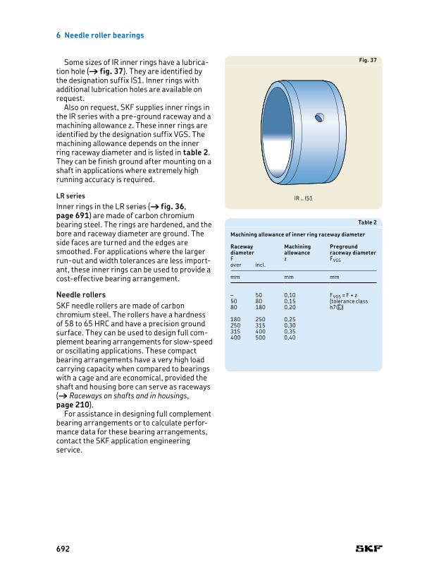
Some sizes of IR inner rings have a lubrication hole († fig. 37). They are identified by the designation suffix IS1. Inner rings with additional lubrication holes are available on request.
Also on request, SKF supplies inner rings in the IR series with a preground raceway and a machining allowance z. These inner rings are identified by the designation suffix VGS. The machining allowance depends on the inner ring raceway diameter and is listed in table 2. They can be finish ground after mounting on a shaft in applications where extremely high running accuracy is required.
LR seriesInner rings in the LR series († fig. 36, page 691) are made of carbon chromium bearing steel. The rings are hardened, and the bore and raceway diameter are ground. The side faces are turned and the edges are smoothed. For applications where the larger runout and width tolerances are less im portant, these inner rings can be used to provide a costeffective bearing arrangement.
Needle rollersSKF needle rollers are made of carbon chromium steel. The rollers have a hardness of 58 to 65 HRC and have a precision ground surface. They can be used to design full complement bearing arrangements for slowspeed or oscillating applications. These compact bearing arrangements have a very high load carrying capacity when compared to bearings with a cage and are economical, provided the shaft and housing bore can serve as raceways († Raceways on shafts and in housings, page 210).
For assistance in designing full complement bearing arrangements or to calculate performance data for these bearing arrangements, contact the SKF application engineering service.
Fig. 37
Table 2
Machining allowance of inner ring raceway diameter
Raceway diameter
Machining allowance
Preground raceway diameter
F z FVGSover incl.
mm mm mm
– 50 0,10 FVGS = F + z (tolerance class h7VE )
50 80 0,1580 180 0,20
180 250 0,25250 315 0,30315 400 0,35400 500 0,40
IR .. IS1
692
6
Designs and variants
CagesDepending on their design, series and size, SKF needle roller bearings are fitted with one of the cages shown in table 3 († page 694). The standard cage is not identified in the bearing designation.
The lubricants generally used for rolling bearings do not have a detrimental effect on cage properties. However, some synthetic oils and greases with a synthetic oil base and lubricants containing a high proportion of EP additives, when used at high temperatures, can have a detrimental effect on polyamide cages. For additional information about the suitability of cages, refer to Cages († page 37) and Cage materials († page 152).
Double row needle roller bearingsDouble row needle roller and cage assemblies have a double row cage in the same design as a single row cage († fig. 1, page 675).
Other double row needle roller bearings are equipped with two cage assemblies († fig. 15, page 681 and fig. 16, page 682).
693

6 Needle roller bearings
Table 3
Cages for needle roller bearings
Cages for radial bearings Cages for thrust bearings
Cage characteristics
Cage type Windowtype Windowtype Windowtype Windowtype Windowtype Windowtype Windowtype Snaptype Windowtype
Material Sheet steel or machined steel
Sheet steel or machined steel
Sheet steel Sheet steel Sheet steel or machined steel
Glass fibre reinforced PA66
Sheet steel Glass fibre reinforced PA66
Glass fibre reinforced PA66
Suffix – – – – – TN – – –
Bearing types
Needle roller and cage assemblies
Standard – Standard – – Standard – – –
Drawn cup needle roller bearings
– – – Standard – Standard – – –
Needle roller bearings with machined rings
– Standard – – Standard Standard – – –
Alignment needle roller bearings
– Standard – – Standard – – – –
Needle roller / angular contact ball bearing
– Standard – – Standard – – Standard –
Needle roller / thrust ball bearing
– Standard – – Standard Standard Standard – –
Needle roller / cylindrical roller thrust bearing
– Standard – – Standard – – – Standard
694

6
Designs and variants
Table 3
Cages for needle roller bearings
Cages for radial bearings Cages for thrust bearings
Cage characteristics
Cage type Windowtype Windowtype Windowtype Windowtype Windowtype Windowtype Windowtype Snaptype Windowtype
Material Sheet steel or machined steel
Sheet steel or machined steel
Sheet steel Sheet steel Sheet steel or machined steel
Glass fibre reinforced PA66
Sheet steel Glass fibre reinforced PA66
Glass fibre reinforced PA66
Suffix – – – – – TN – – –
Bearing types
Needle roller and cage assemblies
Standard – Standard – – Standard – – –
Drawn cup needle roller bearings
– – – Standard – Standard – – –
Needle roller bearings with machined rings
– Standard – – Standard Standard – – –
Alignment needle roller bearings
– Standard – – Standard – – – –
Needle roller / angular contact ball bearing
– Standard – – Standard – – Standard –
Needle roller / thrust ball bearing
– Standard – – Standard Standard Standard – –
Needle roller / cylindrical roller thrust bearing
– Standard – – Standard – – – Standard
695

6 Needle roller bearings
Sealing solutions SKF supplies certain needle roller bearings capped with a seal or steel cover. The assortment of capped bearings includes the following types:
• drawn cup needle roller bearings, sealed on one or both sides• needle roller bearings with machined rings
in the (R)NA 49 series, sealed on one or both sides• combined needle roller bearings with the
designation suffix Z, steel cover over the thrust part of the bearing
SKF supplies capped bearings filled, as standard, with highquality grease that has good corrosion inhibiting properties († Greases for capped bearings, page 698).
In addition to integral bearing seals, SKF also supplies an assortment of external seals that can be used for needle roller bearing arrangements. Appropriate power transmission seals are listed in the relevant product tables, when available. For information about these seals, refer to the product information, available online at skf.com/seals.
Sealed drawn cup needle roller bearingsFor applications where a sufficiently effective seal is not available, or cannot be used for space reasons, SKF supplies certain drawn cup needle roller bearings as sealed bearings. They include:
• drawn cup needle roller bearings with open ends, sealed on one side, designation suffix RS († fig. 38), available for shaft diam eters ranging from 8 to 50 mm• drawn cup needle roller bearings with open
ends, sealed on both sides, designation suffix .2RS († fig. 39), available for shaft diameters ranging from 8 to 50 mm• sealed drawn cup needle roller bearings
with a closed end, designation suffix RS († fig. 40), available for shaft diameters ranging from 10 to 25 mm
These integral contact seals are made of PUR, FKM or NBR. Sealed drawn cup needle roller bearings are, under normal conditions, an extremely costeffective solution to exclude
Fig. 38
HK .. RS
Fig. 39
HK ...2RS
Fig. 40
BK .. RS
696
6
Designs and variants
solid contaminants and moisture and retain the lubricant in the bearing.
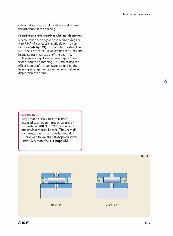
Sealed needle roller bearings with machined ringsNeedle roller bearings with machined rings in the (R)NA 49 series are available with a contact seal († fig. 41) on one or both sides. The NBR seals are effective at keeping the lubricant in and contaminants out of the bearing.
The inner ring of sealed bearings is 1 mm wider than the outer ring. This maintains the effectiveness of the seals and simplifies the bearing arrangements even when small axial displacements occur.
Fig. 41
NA 49 .. RS NA 49 ...2RS
WARNINGSeals made of FKM (fluoro rubber) exposed to an open flame or temperatures above 300 °C (570 °F) are a health and environmental hazard! They remain dangerous even after they have cooled.
Read and follow the safety precautions under Seal materials († page 155).
697
6 Needle roller bearings
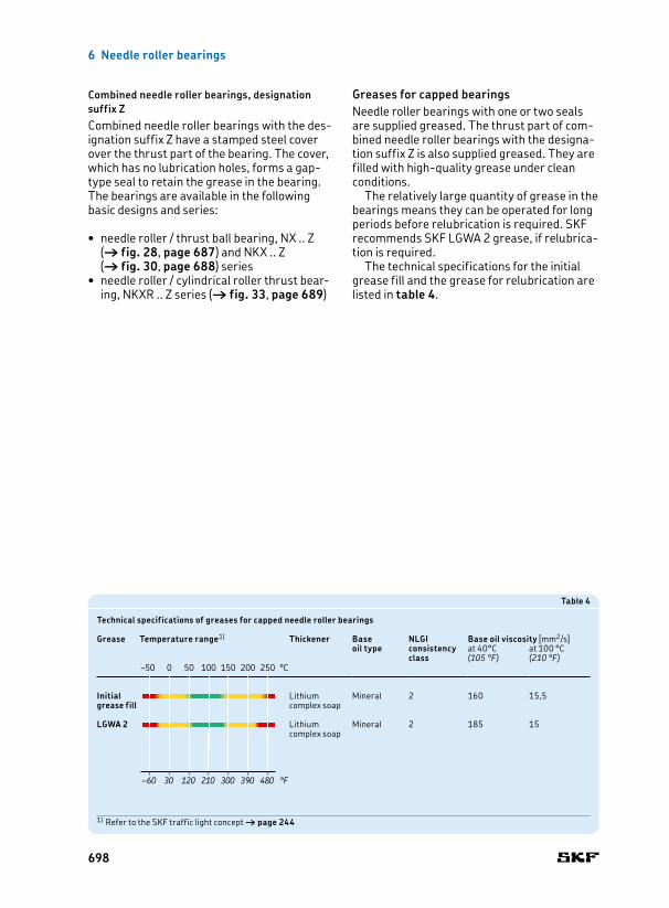
Greases for capped bearingsNeedle roller bearings with one or two seals are supplied greased. The thrust part of combined needle roller bearings with the designation suffix Z is also supplied greased. They are filled with highquality grease under clean conditions.
The relatively large quantity of grease in the bearings means they can be operated for long periods before relubrication is required. SKF recommends SKF LGWA 2 grease, if relubrication is required.
The technical specifications for the initial grease fill and the grease for relubrication are listed in table 4.
Combined needle roller bearings, designation suffix ZCombined needle roller bearings with the designation suffix Z have a stamped steel cover over the thrust part of the bearing. The cover, which has no lubrication holes, forms a gaptype seal to retain the grease in the bearing. The bearings are available in the following basic designs and series:
• needle roller / thrust ball bearing, NX .. Z († fig. 28, page 687) and NKX .. Z († fig. 30, page 688) series
• needle roller / cylindrical roller thrust bearing, NKXR .. Z series († fig. 33, page 689)
Table 4
Technical specifications of greases for capped needle roller bearings
Grease
Temperature range1)
Thickener
Base oil type
NLGI consistencyclass
Base oil viscosity [mm2/s]at 40°C at 100 °C(105 °F) (210 °F)
Initial grease fill
Lithium complex soap
Mineral 2 160 15,5
LGWA 2 Lithium complex soap
Mineral 2 185 15
–50 0 50 100 150 200 250 °C
–60 30 120 210 300 390 480 °F
–50 0 50 100 150 200 250 °C
–60 30 120 210 300 390 480 °F
1) Refer to the SKF traffic light concept † page 244
698

6
Designs and variants
Relubrication facilitiesDepending on the design and size, SKF supplies needle roller bearings with different features to facilitate efficient lubrication and relubrication.
Drawn cup needle roller bearingsSKF supplies all double row drawn cup bearings with one lubrication hole in the outer ring († fig. 8, page 678), as standard.
On request, SKF can supply any single row drawn cup needle roller bearing for inside diameters under the rollers Fw ≥ 7 mm with a lubrication hole in the outer ring († fig. 42).
Needle roller bearings with machined ringsAll needle roller bearings with machined rings and flanges, with an outside diameter D ≥ 19 mm (F, Fw ≥ 12 mm) have an annular groove and, depending on the bearing size, one or more lubrication holes in the outer ring († fig. 14, page 681). Sealed needle roller bearings have an additional lubrication hole in the inner ring († fig. 41, page 697).
Double row machined needle roller bearings without flanges have an annular groove with one lubrication hole in the outer ring († fig. 16, page 682). For single row bearings without flanges and with an inner ring, SKF supplies certain sizes with one lubrication hole in the inner ring. They are not identified by any designation suffix but are marked in the product tables by a footnote.
Combined needle roller bearingsThe needle roller bearing of all combined bearings has an annular groove with one lubrication hole in the outer ring.
Needle roller / full complement thrust ball bearings in the NX series without the designation suffix Z have a cover with lubrication holes over the thrust part of the bearing († fig. 24, page 686). Most often they are oil lubricated and, therefore, SKF supplies these bearings without grease.
Fig. 42
699

6 Needle roller bearings
Bearing dataNeedle roller and cage assemblies Drawn cup needle roller bearings
Dimension standards
ISO 3030 when Fw ≤ 100 mm, as far as standardized Boundary dimensions: ISO 3245, as far as standardized
Tolerances
For additional information († page 132)
• rollers: ISO 3096 Grade 2 (grade G2) – tolerance of each gauge 2 μm – standard and special gauges († table 5, page 707) – specific gauge to be stated when ordering
• U: ISO 3030 as far as standardized (–0,2/–0,8 mm)
ISO 3245 as far as standardized• Fw: ≈ within F8 († table 6, page 707)
Measuring of Fw: – bearing must be pressed into a thickwalled ring gauge, bore diameter listed in table 6 († page 707)
– check deviation of Fw with measuring mandrel• C: 0/–0,3 mm
Dimensional accuracy can be checked only if bearings are mounted.
Operating clearance
Range of C2 to Normal if:•fittedwithstandardgaugerollers(† table 5, page 707) •recommendedracewaytolerances(† table 10, page 709) applied•normaloperatingconditions
Range of C2 to C3 if recommended tolerances († table 15, page 716) applied
Internal clearance Specific ranges: († table 12, page 709) –
Misalignment ≈ 1 minute of arc ≈ 1 minute of arc
Friction, starting torque, power loss
Frictional moment, starting torque, and power loss can be calculated as specified under Friction († page 97), or using the tools available online at skf.com/bearingcalculator.
Defect frequencies
Defect frequencies can be calculated using the tools available online at skf.com/bearingcalculator.
The permissible angular misalignment between the shaft and the housing depends on the size and internal design of the bearing, the radial internal clearance in operation and the forces and moments acting …
700

6
Bearing data
Bearing dataNeedle roller and cage assemblies Drawn cup needle roller bearings
Dimension standards
ISO 3030 when Fw ≤ 100 mm, as far as standardized Boundary dimensions: ISO 3245, as far as standardized
Tolerances
For additional information († page 132)
• rollers: ISO 3096 Grade 2 (grade G2) – tolerance of each gauge 2 μm – standard and special gauges († table 5, page 707) – specific gauge to be stated when ordering
• U: ISO 3030 as far as standardized (–0,2/–0,8 mm)
ISO 3245 as far as standardized• Fw: ≈ within F8 († table 6, page 707)
Measuring of Fw: – bearing must be pressed into a thickwalled ring gauge, bore diameter listed in table 6 († page 707)
– check deviation of Fw with measuring mandrel• C: 0/–0,3 mm
Dimensional accuracy can be checked only if bearings are mounted.
Operating clearance
Range of C2 to Normal if:•fittedwithstandardgaugerollers(† table 5, page 707) •recommendedracewaytolerances(† table 10, page 709) applied•normaloperatingconditions
Range of C2 to C3 if recommended tolerances († table 15, page 716) applied
Internal clearance Specific ranges: († table 12, page 709) –
Misalignment ≈ 1 minute of arc ≈ 1 minute of arc
Friction, starting torque, power loss
Frictional moment, starting torque, and power loss can be calculated as specified under Friction († page 97), or using the tools available online at skf.com/bearingcalculator.
Defect frequencies
Defect frequencies can be calculated using the tools available online at skf.com/bearingcalculator.
… on the bearing. As a result, only approximate values are listed here. Any misalignment increases bearing noise and reduces bearing service life.
701
6 Needle roller bearings
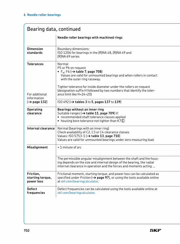
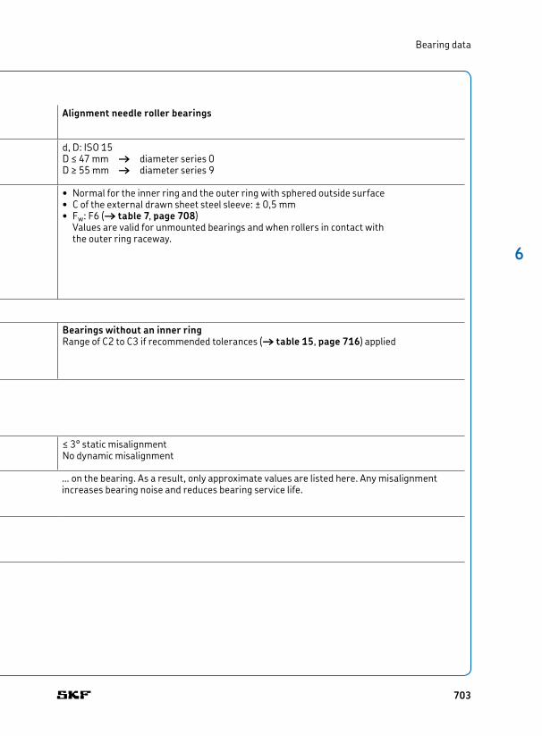
Bearing data, continuedNeedle roller bearings with machined rings Alignment needle roller bearings
Dimension standards
Boundary dimensions: ISO 1206 for bearings in the (R)NA 48, (R)NA 49 and (R)NA 69 series
d, D: ISO 15D ≤ 47 mm † diameter series 0D ≥ 55 mm † diameter series 9
Tolerances
For additional information († page 132)
NormalP5 or P6 on request• Fw: F6 († table 7, page 708)
Values are valid for unmounted bearings and when rollers in contact with the outer ring raceway.
Tighter tolerance for inside diameter under the rollers on request (designation suffix H followed by two numbers that identify the tolerance limit like H+24+20)
• Normal for the inner ring and the outer ring with sphered outside surface• C of the external drawn sheet steel sleeve: ± 0,5 mm• Fw: F6 († table 7, page 708)
Values are valid for unmounted bearings and when rollers in contact with the outer ring raceway.
ISO 492 († tables 3 to 5, pages 137 to 139)
Operating clearance
Bearings without an inner ring Suitable ranges († table 11, page 709) if:• recommended shaft tolerance classes applied • housing bore tolerance not tighter than K7VE
Bearings without an inner ring Range of C2 to C3 if recommended tolerances († table 15, page 716) applied
Internal clearance Normal (bearings with an inner ring)Check availability of C2, C3 or C4 clearance classesValues: ISO 57531 († table 13, page 710)Values are valid for unmounted bearings under zero measuring load.
Misalignment ≈ 1 minute of arc ≤ 3° static misalignment No dynamic misalignment
Friction, starting torque, power loss
Frictional moment, starting torque, and power loss can be calculated as specified under Friction († page 97), or using the tools available online at skf.com/bearingcalculator.
Defect frequencies
Defect frequencies can be calculated using the tools available online at skf.com/bearingcalculator.
The permissible angular misalignment between the shaft and the housing depends on the size and internal design of the bearing, the radial internal clearance in operation and the forces and moments acting …
702
6
Bearing data
Bearing data, continuedNeedle roller bearings with machined rings Alignment needle roller bearings
Dimension standards
Boundary dimensions: ISO 1206 for bearings in the (R)NA 48, (R)NA 49 and (R)NA 69 series
d, D: ISO 15D ≤ 47 mm † diameter series 0D ≥ 55 mm † diameter series 9
Tolerances
For additional information († page 132)
NormalP5 or P6 on request• Fw: F6 († table 7, page 708)
Values are valid for unmounted bearings and when rollers in contact with the outer ring raceway.
Tighter tolerance for inside diameter under the rollers on request (designation suffix H followed by two numbers that identify the tolerance limit like H+24+20)
• Normal for the inner ring and the outer ring with sphered outside surface• C of the external drawn sheet steel sleeve: ± 0,5 mm• Fw: F6 († table 7, page 708)
Values are valid for unmounted bearings and when rollers in contact with the outer ring raceway.
ISO 492 († tables 3 to 5, pages 137 to 139)
Operating clearance
Bearings without an inner ring Suitable ranges († table 11, page 709) if:• recommended shaft tolerance classes applied • housing bore tolerance not tighter than K7VE
Bearings without an inner ring Range of C2 to C3 if recommended tolerances († table 15, page 716) applied
Internal clearance Normal (bearings with an inner ring)Check availability of C2, C3 or C4 clearance classesValues: ISO 57531 († table 13, page 710)Values are valid for unmounted bearings under zero measuring load.
Misalignment ≈ 1 minute of arc ≤ 3° static misalignment No dynamic misalignment
Friction, starting torque, power loss
Frictional moment, starting torque, and power loss can be calculated as specified under Friction († page 97), or using the tools available online at skf.com/bearingcalculator.
Defect frequencies
Defect frequencies can be calculated using the tools available online at skf.com/bearingcalculator.
… on the bearing. As a result, only approximate values are listed here. Any misalignment increases bearing noise and reduces bearing service life.
703
6 Needle roller bearings
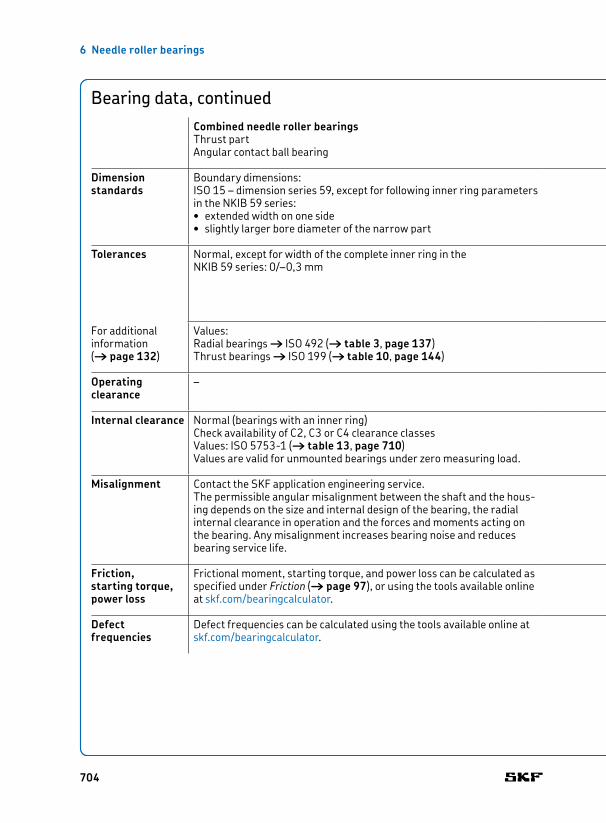
Bearing data, continuedCombined needle roller bearingsThrust partAngular contact ball bearing Thrust ball bearing Cylindrical roller thrust bearing
Dimension standards
Boundary dimensions: ISO 15 – dimension series 59, except for following inner ring parameters in the NKIB 59 series:• extended width on one side• slightly larger bore diameter of the narrow part
Boundary dimensions: DIN 54291, except for the bearings in the NX and NX .. Z series that are not standardized.
Boundary dimensions: DIN 54291
Tolerances
For additional information († page 132)
Normal, except for width of the complete inner ring in the NKIB 59 series: 0/–0,3 mm
• D: Normal• Fw: F6 († table 7, page 708)• d: E8 († table 7, page 708)• C: 0/–0,25 mm• C1 (applicable to NKX and NKXR series only): 0/–0,2 mm
Values: Radial bearings † ISO 492 († table 3, page 137)Thrust bearings † ISO 199 († table 10, page 144)
Operating clearance
– Bearings without an inner ring Range slightly less than Normal if recommended tolerances († table 17, page 717) applied
Internal clearance Normal (bearings with an inner ring)Check availability of C2, C3 or C4 clearance classesValues: ISO 57531 († table 13, page 710)Values are valid for unmounted bearings under zero measuring load.
Misalignment Contact the SKF application engineering service.The permissible angular misalignment between the shaft and the housing depends on the size and internal design of the bearing, the radial internal clearance in operation and the forces and moments acting on the bearing. Any misalignment increases bearing noise and reduces bearing service life.
Cannot tolerate any angular misalignment between shaft and housing or between shaft and axial support surfaces in the housing.
Friction, starting torque, power loss
Frictional moment, starting torque, and power loss can be calculated as specified under Friction († page 97), or using the tools available online at skf.com/bearingcalculator.
Defect frequencies
Defect frequencies can be calculated using the tools available online at skf.com/bearingcalculator.
704

6
Bearing data
Bearing data, continuedCombined needle roller bearingsThrust partAngular contact ball bearing Thrust ball bearing Cylindrical roller thrust bearing
Dimension standards
Boundary dimensions: ISO 15 – dimension series 59, except for following inner ring parameters in the NKIB 59 series:• extended width on one side• slightly larger bore diameter of the narrow part
Boundary dimensions: DIN 54291, except for the bearings in the NX and NX .. Z series that are not standardized.
Boundary dimensions: DIN 54291
Tolerances
For additional information († page 132)
Normal, except for width of the complete inner ring in the NKIB 59 series: 0/–0,3 mm
• D: Normal• Fw: F6 († table 7, page 708)• d: E8 († table 7, page 708)• C: 0/–0,25 mm• C1 (applicable to NKX and NKXR series only): 0/–0,2 mm
Values: Radial bearings † ISO 492 († table 3, page 137)Thrust bearings † ISO 199 († table 10, page 144)
Operating clearance
– Bearings without an inner ring Range slightly less than Normal if recommended tolerances († table 17, page 717) applied
Internal clearance Normal (bearings with an inner ring)Check availability of C2, C3 or C4 clearance classesValues: ISO 57531 († table 13, page 710)Values are valid for unmounted bearings under zero measuring load.
Misalignment Contact the SKF application engineering service.The permissible angular misalignment between the shaft and the housing depends on the size and internal design of the bearing, the radial internal clearance in operation and the forces and moments acting on the bearing. Any misalignment increases bearing noise and reduces bearing service life.
Cannot tolerate any angular misalignment between shaft and housing or between shaft and axial support surfaces in the housing.
Friction, starting torque, power loss
Frictional moment, starting torque, and power loss can be calculated as specified under Friction († page 97), or using the tools available online at skf.com/bearingcalculator.
Defect frequencies
Defect frequencies can be calculated using the tools available online at skf.com/bearingcalculator.
705

6 Needle roller bearings
Bearing data, continuedNeedle roller bearing components
Needle roller bearing inner rings Needle rollers
Dimension standards
– ISO 3096, except for RN2x6.3 BF/G2 that is not standardized
Tolerances
For additional information († page 132)
IR seriesNormalValues: ISO 492 († table 3, page 137)
LR series• F: h6• B: h12• d: K6
Values: († table 8, page 708)
ISO 3096 Grade 2 for flat end needle rollersAvailable tolerances († table 9, page 708)
Operating clearance
Depends on the bearing type with which the inner ring is combined with.
–
Internal clearance Depends on the bearing type with which the inner ring is combined with.
–
706

6
Bearing data
Table 6
Tolerances for drawn cup needle roller bearings
Bearing Ring gauge Deviations from nominalInside diameter Outside diameter Bore diameter inside diameterFw D (measured) high low
mm mm μm
3 6,5 6,484 +24 +64 8 7,984 +28 +105 9 8,984 +28 +10
6 10 9,984 +28 +107 11 10,980 +31 +138 12 11,980 +31 +13
9 13 12,980 +31 +1310 14 13,980 +31 +1312 16 15,980 +34 +1612 18 17,980 +34 +16
13 19 18,976 +34 +1614 20 19,976 +34 +1615 21 20,976 +34 +16
16 22 21,976 +34 +1617 23 22,976 +34 +1618 24 23,976 +34 +16
20 26 25,976 +41 +2022 28 27,976 +41 +2025 32 31,972 +41 +20
28 35 34,972 +41 +2030 37 36,972 +41 +2032 39 38,972 +50 +25
35 42 41,972 +50 +2540 47 46,972 +50 +2545 52 51,967 +50 +25
50 58 57,967 +50 +2555 63 62,967 +60 +3060 68 67,967 +60 +30
Table 5
Needle roller gauges
Gauge type Gauge
– μm
Standard gauges 0/−2−1/−3−2/−4−3/−5−4/−6−5/−7
Special gauges −6/−8(to order) −7/−9
−8/−10−9/−11
707

6 Needle roller bearings
Table 7
ISO tolerance classes
Nominal diameter
E8VE F6VEDeviation Deviation
over incl. high low high low
mm μm μm
– 3 – – +12 +63 6 – – +18 +106 10 +47 +25 +22 +13
10 18 +59 +32 +27 +1618 30 +73 +40 +33 +2030 50 +89 +50 +41 +25
50 80 +106 +60 +49 +3080 120 – – +58 +36120 180 – – +68 +43
180 250 – – +79 +50250 315 – – +88 +56315 400 – – +98 +62
400 500 – – +108 +68
Table 8
ISO tolerance classes for LR series inner rings
Nominal dimension
h6VE h12VE K6VEDeviations Deviations Deviations
over incl. high low high low high low
mm μm μm μm
6 10 0 –9 – – +2 –710 18 0 –11 0 –180 +2 –918 30 0 –13 0 –210 +2 –11
30 50 0 –16 0 –250 +3 –1350 80 0 –19 – – – –
Table 9
Dimensional and geometrical accuracy of SKF needle rollers, grade G2
Diameter Dw Length LwDeviation Gauge
toleranceGauge limits
Roundness (max. circularity deviation in accordance with ISO 3096)
Tolerance class
high low
μm –
0 10 2 0/–2 1 h13VE–1/–3–2/–4–3/–5–4/–6–5/–7–6/–8–7/–9–8/–10
Preferred diameter deviations range from 0 to –7 μm. Each gauge is packed separately and marked with the gauge limits, e.g. N/M2 or M2/M4, where M signifies minus and N zero. For a needle roller with a 2 mm nominal diameter and gauge limits M2/M4, the actual diameter is between 1,998 mm and 1,996 mm.
708

6
Bearing data
Table 12
Mounting scheme – example
Needle roller and cage assembly: K 16¥22¥12Housing bore diameter: 22H6VE [mm], deviation 0/+13 μmShaft diameter: 16h5VE [mm], deviation 0/–8 μm
Shaft diameter Housing bore diameterDeviation group Deviation groups
0 to +3 +3 to +6 +6 to +9 +9 to +13Needle roller gauge limits
Radial internal clearance
Needle roller gauge limits
Radial internal clearance
Needle roller gauge limits
Radial internal clearance
Needle roller gauge limits
Radial internal clearance
μm μm
0 to −3 –5/–7 18–24 –3/–5 17–24
−3 to −6 –5/–7 18–24 –3/–5 17–25 –2/–4 18–25–4/–6
−6 to –8 –5/−7 18–25 –3/–5 17–24 –2/–4 18–25 0/–2 17–25−6/−8 –4/–6 –3/–5 –1/–3
The mean value of the needle roller gauge should be used to calculate the internal clearance, e.g. –6 μm for the gauge –5 to –7 μm.
Table 10
Raceway tolerance classes for needle roller and cage assemblies
Shaft Housing/shaft tolerance classes1)
Nominal diameter for operating clearanceover incl. lower side medium higher side
mm –
– 80 G6/j5 G6/h5 G6/g6H6/h5 H6/g5 H6/f6
80 120 G6/h5 G6/g5 G6/f6
120 – G6/h5 G6/g5 G6/f6– H6/f5 H6/e6
1) All ISO tolerance classes are valid with the envelope requirement (such as H7VE ) in accordance with ISO 144051.
Table 11
Shaft tolerance classes for machined needle roller bearings without an inner ring
Nominal inside diameter
Shaft tolerance classes1) for shaft raceways to give operating clearance
Fw lower side medium higher sideover incl.
mm –
– 65 k5 h5 g665 80 k5 h5 f680 160 k5 g5 f6
160 180 k5 g5 e6180 200 j5 g5 e6200 250 j5 f6 e6
250 315 h5 f6 e6315 400 g5 f6 d6
1) All ISO tolerance classes are valid with the envelope requirement (such as h7VE ) in accordance with ISO 144051.
709

6 Needle roller bearings
Table 13
Radial internal clearance for needle roller bearings
Bore diameter Radial internal clearanced C2 Normal C3 C4over incl. min. max. min. max. min. max. min. max.
mm μm
– 30 0 25 20 45 35 60 50 7530 40 5 30 25 50 45 70 60 8540 50 5 35 30 60 50 80 70 100
50 65 10 40 40 70 60 90 80 11065 80 10 45 40 75 65 100 90 12580 100 15 50 50 85 75 110 105 140
100 120 15 55 50 90 85 125 125 165120 140 15 60 60 105 100 145 145 190140 160 20 70 70 120 115 165 165 215
160 180 25 75 75 125 120 170 170 220180 200 35 90 90 145 140 195 195 250200 225 45 105 105 165 160 220 220 280
225 250 45 110 110 175 170 235 235 300250 280 55 125 125 195 190 260 260 330280 315 55 130 130 205 200 275 275 350
315 355 65 145 145 225 225 305 305 385355 400 100 190 190 280 280 370 370 460
710

6
Loads
LoadsNeedle rollers and cage assemblies
Drawn cup needle roller bearings1)
Needle roller bearings with machined rings
Alignment needle roller bearings
Minimum load
For additional information († page 86)
Frm = 0,02 C
The weight of the components supported by the bearing, together with external forces, generally exceed the requisite minimum load. If this is not the case, the bearing must be subjected to an additional radial load.
Equivalent dy nam ic bearing load
For additional information († page 85)
P = Fr
Equivalent static bearing load
For additional information († page 88)
P0 = Fr
Symbols C = basic dynamic load rating [kN] († product tables)Fr = radial load [kN]Frm = minimum radial load [kN]P = equivalent dynamic bearing load [kN]P0 = equivalent static bearing load [kN]s0 = static safety factor
1) SKF recommends applying a static safety factor s0 ≥ 3, i.e. s0 = C0/P0 ≥ 3.
711
6 Needle roller bearings
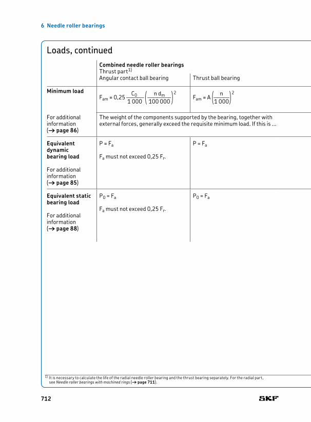
Loads, continuedCombined needle roller bearingsThrust part1)
Symbols
Angular contact ball bearing Thrust ball bearing Cylindrical roller thrust bearing
Minimum load
For additional information († page 86)
C0 q n dm
w2Fam = 0,25 JJJ JKJJL 1 000 < 100 000 z
q n w2Fam = A KJJ < 1 000 z
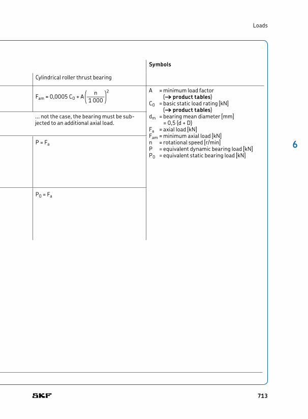
q n w2Fam = 0,0005 CO + A JJJ < 1 000 z
A = minimum load factor († product tables)
C0 = basic static load rating [kN] († product tables)
dm = bearing mean diameter [mm] = 0,5 (d + D)
Fa = axial load [kN]Fam = minimum axial load [kN]n = rotational speed [r/min]P = equivalent dynamic bearing load [kN]P0 = equivalent static bearing load [kN]
Equivalent dy nam ic bearing load
For additional information († page 85)
P = Fa
Fa must not exceed 0,25 Fr.
P = Fa P = Fa
Equivalent static bearing load
For additional information († page 88)
P0 = Fa
Fa must not exceed 0,25 Fr.
P0 = Fa P0 = Fa
1) It is necessary to calculate the life of the radial needle roller bearing and the thrust bearing separately. For the radial part, see Needle roller bearings with machined rings († page 711).
The weight of the components supported by the bearing, together with external forces, generally exceed the requisite minimum load. If this is ...
712
6
Loads
Loads, continuedCombined needle roller bearingsThrust part1)
Symbols
Angular contact ball bearing Thrust ball bearing Cylindrical roller thrust bearing
Minimum load
For additional information († page 86)
C0 q n dm
w2Fam = 0,25 JJJ JKJJL 1 000 < 100 000 z
q n w2Fam = A KJJ < 1 000 z
q n w2Fam = 0,0005 CO + A JJJ < 1 000 z
A = minimum load factor († product tables)
C0 = basic static load rating [kN] († product tables)
dm = bearing mean diameter [mm] = 0,5 (d + D)
Fa = axial load [kN]Fam = minimum axial load [kN]n = rotational speed [r/min]P = equivalent dynamic bearing load [kN]P0 = equivalent static bearing load [kN]
Equivalent dy nam ic bearing load
For additional information († page 85)
P = Fa
Fa must not exceed 0,25 Fr.
P = Fa P = Fa
Equivalent static bearing load
For additional information († page 88)
P0 = Fa
Fa must not exceed 0,25 Fr.
P0 = Fa P0 = Fa
1) It is necessary to calculate the life of the radial needle roller bearing and the thrust bearing separately. For the radial part, see Needle roller bearings with machined rings († page 711).
... not the case, the bearing must be subjected to an additional axial load.
713
6 Needle roller bearings
Temperature limitsThe permissible operating temperature for needle roller bearings can be limited by:
• the dimensional stability of the bearing rings and rollers• the cages• the seals• the seating rings• the lubricant
When temperatures outside the permissible range are expected, contact the SKF application engineering service.
Bearing rings and rollersSKF needle roller bearings undergo a special heat treatment. The bearings are heat stabilized up to at least 120 °C (250 °F).
Drawn cup needle roller bearings are heat stabilized up to at least 140 °C (285 °F).
CagesSteel cages can be used at the same operating temperatures as the bearing rings and rollers. For temperature limits of polymer cages, refer to Cage materials († page 152).
SealsThe permissible operating temperature for seals depends on the material:
• NBR seals: –40 to + 100 °C (–40 to +210 °F)Temperatures up to 120 °C (250 °F) can be tolerated for brief periods. • PUR seals:
–30 to +100 °C (–20 to +210 °F)• FKM seals:
–30 to +200 °C (–20 to +390 °F)
Seating ringsThe permissible operating temperature for seating rings fitted to alignment needle roller bearings is –30 to +100 °C (–20 to +210 °F).
LubricantsTemperature limits for the grease used in capped needle roller bearings are provided in table 4 († page 698) and for full complement drawn cup needle roller bearings in table 1 († page 679). Temperature limits for other
SKF greases are provided under Lubrication († page 239).
When using lubricants not supplied by SKF, the temperature limits should be evaluated according to the SKF traffic light concept († page 244).
Permissible speedThe permissible speed can be estimated using the speed ratings listed in the product tables and applying the information provided under Speeds († page 117). If no reference speed is listed in the product tables, the limiting speed is the permissible speed.
Design of bearing arrangementsAbutment dimensions
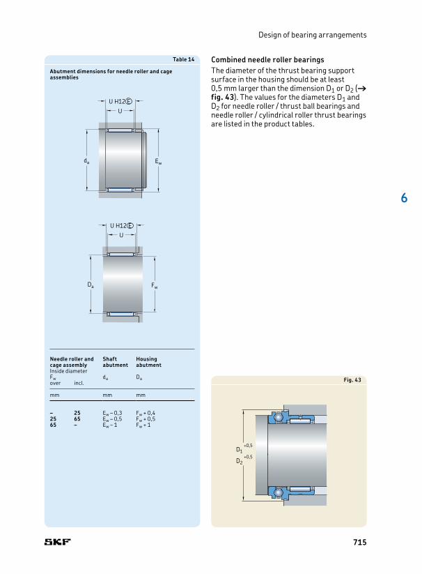
Needle roller and cage assembliesNeedle roller and cage assemblies should be guided axially by the fine turned and polished surfaces of adjacent machine components. For highspeed operations they should be hardened and ground. Appropriate abutment diameters are provided in table 14.
Interruptions in the surface of adjacent machine components should be avoided. Snap rings can be used in less demanding applications, otherwise an intermediate ring, e.g. a spring steel washer, should be mounted between the snap ring and the cage assembly.
Needle roller bearings with machined rings, without flangesThe cage of needle roller bearings without flanges should be guided axially by the fine turned and polished surfaces of adjacent machine components. Appropriate abutment diameters are listed in the product tables.
714
6
Design of bearing arrangements
Combined needle roller bearingsThe diameter of the thrust bearing support surface in the housing should be at least 0,5 mm larger than the dimension D1 or D2 († fig. 43). The values for the diameters D1 and D2 for needle roller / thrust ball bearings and needle roller / cylindrical roller thrust bearings are listed in the product tables.
Table 14
Abutment dimensions for needle roller and cage assemblies
Needle roller and cage assembly
Shaft abutment
Housing abutment
Inside diameterFw da Daover incl.
mm mm mm
– 25 Ew – 0,3 Fw + 0,425 65 Ew – 0,5 Fw + 0,565 – Ew – 1 Fw + 1
U
da Ew
U H12 E
U
Da Fw
U H12 E
D1 +0,5
D2 +0,5
Fig. 43
715
6 Needle roller bearings
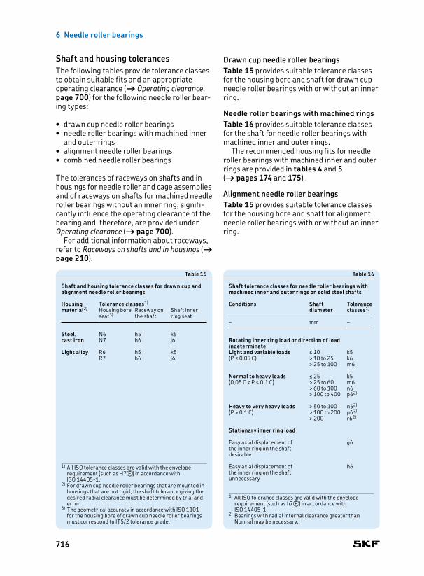
Drawn cup needle roller bearingsTable 15 provides suitable tolerance classes for the housing bore and shaft for drawn cup needle roller bearings with or without an inner ring.
Needle roller bearings with machined ringsTable 16 provides suitable tolerance classes for the shaft for needle roller bearings with machined inner and outer rings.
The recommended housing fits for needle roller bearings with machined inner and outer rings are provided in tables 4 and 5 († pages 174 and 175) .
Alignment needle roller bearingsTable 15 provides suitable tolerance classes for the housing bore and shaft for alignment needle roller bearings with or without an inner ring.
Shaft and housing tolerances The following tables provide tolerance classes to obtain suitable fits and an appropriate operating clearance († Operating clearance, page 700) for the following needle roller bearing types:
• drawn cup needle roller bearings• needle roller bearings with machined inner
and outer rings• alignment needle roller bearings• combined needle roller bearings
The tolerances of raceways on shafts and in housings for needle roller and cage assemblies and of raceways on shafts for machined needle roller bearings without an inner ring, significantly influence the operating clearance of the bearing and, therefore, are provided under Operating clearance († page 700).
For additional information about raceways, refer to Raceways on shafts and in housings († page 210).
Table 15
Shaft and housing tolerance classes for drawn cup and alignment needle roller bearings
Housing material2)
Tolerance classes1)
Housing bore seat3)
Raceway on the shaft
Shaft inner ring seat
Steel, cast iron
N6 h5 k5N7 h6 j6
Light alloy R6 h5 k5R7 h6 j6
1) All ISO tolerance classes are valid with the envelope requirement (such as H7VE ) in accordance with ISO 144051.
2) For drawn cup needle roller bearings that are mounted in housings that are not rigid, the shaft tolerance giving the desired radial clearance must be determined by trial and error.
3) The geometrical accuracy in accordance with ISO 1101 for the housing bore of drawn cup needle roller bearings must correspond to IT5/2 tolerance grade.
1) All ISO tolerance classes are valid with the envelope requirement (such as h7VE ) in accordance with ISO 144051.
2) Bearings with radial internal clearance greater than Normal may be necessary.
Table 16
Shaft tolerance classes for needle roller bearings with machined inner and outer rings on solid steel shafts
Conditions Shaftdiameter
Tolerance classes1)
– mm –
Rotating inner ring load or direction of load indeterminateLight and variable loads ≤ 10 k5(P ≤ 0,05 C) > 10 to 25 k6
> 25 to 100 m6
Normal to heavy loads ≤ 25 k5(0,05 C < P ≤ 0,1 C) > 25 to 60 m6
> 60 to 100 n6> 100 to 400 p62)
Heavy to very heavy loads > 50 to 100 n62)
(P > 0,1 C) > 100 to 200 p62)
> 200 r62)
Stationary inner ring load
Easy axial displacement of the inner ring on the shaft desirable
g6
Easy axial displacement of the inner ring on the shaft unnecessary
h6
716

6
Design of bearing arrangements
Combined needle roller bearingsTable 17 provides suitable tolerance classes for the housing bore and shaft for combined needle roller bearings with or without an inner ring.
Table 17
Shaft and housing tolerance classes for combined needle roller bearings
Thrust part Tolerance classes1)
Housing bore seat
Shaft seat (raceway and inner ring seat)
Angular contact ball bearing
M6 k5
Thrust ball bearing K62) k5
Cylindrical roller thrust bearing
K62) k5
1) All ISO tolerance classes are valid with the envelope requirement (such as H7VE ) in accordance with ISO 144051.
2) For stiff bearing arrangements, SKF recommends an M6VE housing bore tolerance class.
717
6 Needle roller bearings
Fw –0,025
D–0,2–0,3
15°
Fig.44
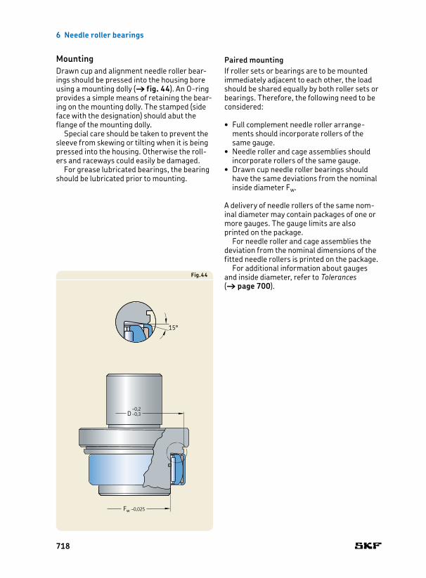
MountingDrawn cup and alignment needle roller bearings should be pressed into the housing bore using a mounting dolly († fig. 44). An Oring provides a simple means of retaining the bearing on the mounting dolly. The stamped (side face with the designation) should abut the flange of the mounting dolly.
Special care should be taken to prevent the sleeve from skewing or tilting when it is being pressed into the housing. Otherwise the rollers and raceways could easily be damaged.
For grease lubricated bearings, the bearing should be lubricated prior to mounting.
Paired mounting If roller sets or bearings are to be mounted immediately adjacent to each other, the load should be shared equally by both roller sets or bearings. Therefore, the following need to be considered:
• Full complement needle roller arrangements should incorporate rollers of the same gauge.• Needle roller and cage assemblies should
incorporate rollers of the same gauge.• Drawn cup needle roller bearings should
have the same deviations from the nominal inside diameter Fw.
A delivery of needle rollers of the same nomin al diameter may contain packages of one or more gauges. The gauge limits are also printed on the package.
For needle roller and cage assemblies the deviation from the nominal dimensions of the fitted needle rollers is printed on the package.
For additional information about gauges and inside diameter, refer to Tolerances († page 700).
718

6
Design of bearing arrangements
719

6 Needle roller bearings
Designation system
Prefixes
R Bearing without an inner ring
Basic designation
BK Drawn cup needle roller bearing with a closed endHK Drawn cup needle roller bearing with open endsHN Drawn cup needle roller bearing with open ends, full complementIR Needle roller bearing inner ringK Needle roller and cage assemblyLR Needle roller bearing inner ringNA 48 Needle roller bearing with machined rings, with flanges, with an inner ringNA 49 Needle roller bearing with machined rings, with flanges, with an inner ringNA 69 Needle roller bearing with machined rings, with flanges, with an inner ringNAO Needle roller bearing with machined rings, without flanges, with an inner ringNK Needle roller bearing with machined rings, with flanges, without an inner ringNKI Needle roller bearing with machined rings, with flanges, with an inner ringNKIA 59 Needle roller / angular contact ball bearingNKIB 59 Needle roller / angular contact ball bearingNKIS Needle roller bearing with machined rings, with flanges, with an inner ringNKS Needle roller bearing with machined rings, with flanges, without an inner ringNKX Needle roller / thrust ball bearingNKXR Needle roller / cylindrical roller thrust bearingNX Needle roller / thrust ball bearing, full complement thrust bearingPNA Alignment needle roller bearingRN Needle roller
Suffixes
Group 1: Internal design
BF Needle roller with flat endsD Deviating or modified internal design with the same boundary dimensions. Generally
dropped after a certain changeover period, but may have the significance to bound to the particular bearing design/series. Example: K 40x45x17 D (Needle roller and cage assembly with a double split cage)
DS Single split needle roller and cage assemblyEGS Inner ring with a nondirectionally ground racewayVGS Inner ring with a preground raceway and a machining allowance
Group 2: External design (seals, snap ring groove etc.)
RS Contact seal on one side of a drawn cup needle roller bearing (NBR or FKM or PUR) or machined needle roller bearing (NBR)
.2RS Contact seal on both sides of a drawn cup needle roller bearing (NBR or FKM or PUR) or machined needle roller bearing (NBR)
Z Combined needle roller bearing, factory greased thrust bearing with a cover without lubrication holes over the outside diameter
ZW Double row needle roller and cage assembly (double row cage)
Group 3: Cage design
TN Glass fibre reinforced PA66 cage
Group 1 Group 2 Group 3 / Group 4
4.1 4.2 4.3 4.4 4.5 4.6
720

6
Designation system
Designation system
Prefixes
R Bearing without an inner ring
Basic designation
BK Drawn cup needle roller bearing with a closed endHK Drawn cup needle roller bearing with open endsHN Drawn cup needle roller bearing with open ends, full complementIR Needle roller bearing inner ringK Needle roller and cage assemblyLR Needle roller bearing inner ringNA 48 Needle roller bearing with machined rings, with flanges, with an inner ringNA 49 Needle roller bearing with machined rings, with flanges, with an inner ringNA 69 Needle roller bearing with machined rings, with flanges, with an inner ringNAO Needle roller bearing with machined rings, without flanges, with an inner ringNK Needle roller bearing with machined rings, with flanges, without an inner ringNKI Needle roller bearing with machined rings, with flanges, with an inner ringNKIA 59 Needle roller / angular contact ball bearingNKIB 59 Needle roller / angular contact ball bearingNKIS Needle roller bearing with machined rings, with flanges, with an inner ringNKS Needle roller bearing with machined rings, with flanges, without an inner ringNKX Needle roller / thrust ball bearingNKXR Needle roller / cylindrical roller thrust bearingNX Needle roller / thrust ball bearing, full complement thrust bearingPNA Alignment needle roller bearingRN Needle roller
Suffixes
Group 1: Internal design
BF Needle roller with flat endsD Deviating or modified internal design with the same boundary dimensions. Generally
dropped after a certain changeover period, but may have the significance to bound to the particular bearing design/series. Example: K 40x45x17 D (Needle roller and cage assembly with a double split cage)
DS Single split needle roller and cage assemblyEGS Inner ring with a nondirectionally ground racewayVGS Inner ring with a preground raceway and a machining allowance
Group 2: External design (seals, snap ring groove etc.)
RS Contact seal on one side of a drawn cup needle roller bearing (NBR or FKM or PUR) or machined needle roller bearing (NBR)
.2RS Contact seal on both sides of a drawn cup needle roller bearing (NBR or FKM or PUR) or machined needle roller bearing (NBR)
Z Combined needle roller bearing, factory greased thrust bearing with a cover without lubrication holes over the outside diameter
ZW Double row needle roller and cage assembly (double row cage)
Group 3: Cage design
TN Glass fibre reinforced PA66 cage
Group 4.6: Other variants
VG052 Single split PES (polyethersulfone) cage
Group 4.5: Lubrication
AS.. Outer ring with lubrication hole(s), the number following indicates the number of holes
ASR.. Outer ring with annular groove and lubrication hole(s), the number following indicates the number of holes
IS.. Inner ring with lubrication hole(s), the number following indicates the number of holes
ISR.. Inner ring with annular groove and lubrication hole(s), the number following indicates the number of holes
SM.. Special grease, two numbers following identify the grease
Group 4.4: Stabilization
S0 Bearing heat stabilized for operating temperatures ≤ 150 °C (300 °F)S1 Bearing heat stabilized for operating temperatures ≤ 200 °C (390 °F)S2 Bearing heat stabilized for operating temperatures ≤ 250 °C (480 °F)S3 Bearing heat stabilized for operating temperatures ≤ 300 °C (570 °F)
Group 4.3: Bearing sets, matched bearings
..S Matched bearings for an equal load distribution. The number preceding indicates the number of bearings, e.g. NK 50/25 TN/2S
Group 4.2: Accuracy, clearance, preload, quiet running
/SORT.. Tolerance grade of needle rollers of a needle roller and cage assembly, the numbers following identify the actual limits in μm, e.g. /SORT24
CN Normal radial internal clearance; only used together with an additional letter that identifies a reduced or displaced clearance rangeH Reduced clearance range corresponding to the upper half of the actual clearance
rangeL Reduced clearance range corresponding to the lower half of the actual clearance
rangeM Reduced clearance range corresponding to the two middle quaters of the actual
clearance rangeP Displaced clearance range comprising the upper half of the actual clearance
range plus the lower half of the next larger clearance rangeR Normal clearance range in accordance with the withdrawn DIN 6204:1982The above letters H, L, M and P are also used together with the clearance classes C2, C3, C4
C2 Radial internal clearance smaller than NormalC3 Radial internal clearance greater than NormalC4 Radial internal clearance greater than C3G2 Needle roller in accordance with ISO 3096 Grade 2H.. Bearing without an inner ring and reduced inside diameter (under rollers) tolerance,
the numbers following indicate the tolerance limits in μm, e.g. H+27+20M../M.. Diameter tolerance of needle rollers, e.g. M2/M4 indicates diameter tolerance
–2 to –4 μmN/M.. Diameter tolerance of needle rollers, e.g. N/M2 indicates diameter tolerance
0 to –2 μmP5 Dimensional and running accuracy to P5 tolerance classP6 Dimensional and running accuracy to P6 tolerance classP62 P6 + C2P63 P6 + C3P6CNR P6 + CNR
Group 4.1: Materials, heat treatment
Group 1 Group 2 Group 3 / Group 4
4.1 4.2 4.3 4.4 4.5 4.6
721

3 5 7 1,51 1,34 0,134 40 000 45 000 0,3 K 3x5x7 TN –5 9 1,68 1,53 0,153 40 000 45 000 0,4 K 3x5x9 TN –6 7 1,42 1,02 0,104 38 000 43 000 0,4 K 3x6x7 TN –
4 7 7 1,72 1,32 0,137 36 000 43 000 0,5 K 4x7x7 TN –7 10 2,29 1,9 0,204 36 000 43 000 0,7 K 4x7x10 TN –
5 8 8 2,29 2 0,212 36 000 40 000 0,7 K 5x8x8 TN –8 10 2,92 2,7 0,29 36 000 40 000 0,9 K 5x8x10 TN –
6 9 8 2,55 2,36 0,25 34 000 38 000 0,8 K 6x9x8 TN –9 10 3,3 3,2 0,345 34 000 38 000 1,1 K 6x9x10 TN –10 13 3,69 3,15 0,36 34 000 38 000 1,9 K 6x10x13 TN G 6x10x2 S
7 9 7 1,68 1,83 0,19 34 000 38 000 0,6 K 7x9x7 TN –10 8 2,81 2,75 0,29 32 000 36 000 0,9 K 7x10x8 TN –10 10 3,58 3,75 0,415 32 000 36 000 1 K 7x10x10 TN –
8 11 8 3,03 3,1 0,335 32 000 36 000 1 K 8x11x8 TN –11 10 3,8 4,25 0,465 32 000 36 000 1,2 K 8x11x10 TN –11 13 5,01 5,85 0,67 32 000 36 000 1,7 K 8x11x13 TN –12 10 4,84 4,75 0,54 30 000 34 000 2 K 8x12x10 TN G 8x12x3
9 12 10 4,4 5,2 0,57 30 000 34 000 1,5 K 9x12x10 TN –12 13 5,72 7,2 0,815 30 000 34 000 2,1 K 9x12x13 TN –
10 13 10 4,57 5,7 0,63 28 000 32 000 1,6 K 10x13x10 TN –13 13 5,94 8 0,9 28 000 32 000 2,3 K 10x13x13 TN –13 16 6,82 9,5 1,08 28 000 32 000 2,9 K 10x13x16 TN –14 10 5,61 6,1 0,695 28 000 32 000 2,5 K 10x14x10 TN G 10x14x314 13 7,21 8,5 0,98 28 000 32 000 4,6 K 10x14x13 TN G 10x14x316 12 7,65 7,2 0,85 28 000 32 000 5,5 K 10x16x12 TN –
12 15 10 4,73 6,2 0,695 26 000 30 000 2,9 K 12x15x10 TN –15 13 6,16 8,65 0,98 26 000 30 000 2,3 K 12x15x13 TN –16 13 7,65 9,5 1,1 26 000 30 000 3,6 K 12x16x13 TN G 12x16x317 13 9,13 10,4 1,22 26 000 30 000 4,9 K 12x17x13 TN –18 12 9,52 10 1,18 26 000 30 000 6 K 12x18x12 TN G/SD 12x18x3
FwEw
U
1) For additional information, visit skf.com/seals.
6.1 Needle roller and cage assembliesFw 3 – 22 mm
Principal dimensions
Basic load ratings
Fatigue load limit
Speed ratings Mass Designation Appropriate seal1)
Reference speed
Limiting speed
Designationdynamic static
Fw Ew U C C0 Pu
mm kN kN r/min g – –
722

14 18 10 6,93 8,65 1 24 000 28 000 4 K 14x18x10 –18 13 7,92 10,2 1,18 24 000 28 000 6,5 K 14x18x13 –18 15 9,13 12,5 1,46 24 000 28 000 5 K 14x18x15 TN –18 17 10,5 14,6 1,7 24 000 28 000 8 K 14x18x17 –20 12 9,9 10,6 1,25 24 000 28 000 8,5 K 14x20x12 G/SD 14x20x3
15 18 17 7,65 12,2 1,4 24 000 28 000 4,6 K 15x18x17 TN –19 10 7,21 9,3 1,08 24 000 28 000 5 K 15x19x10 –19 13 8,25 11,2 1,29 24 000 28 000 7 K 15x19x13 –19 17 10,8 15,6 1,86 24 000 28 000 9,5 K 15x19x17 –
20 13 9,52 11,6 1,34 24 000 26 000 7 K 15x20x13 –21 15 13,8 16,3 2 24 000 26 000 11 K 15x21x15 G/SD 15x21x321 21 18,7 24,5 3 24 000 26 000 17 K 15x21x21 G/SD 15x21x3
16 20 10 7,48 10 1,16 24 000 26 000 5,5 K 16x20x10 –20 13 8,58 12 1,37 24 000 26 000 7,5 K 16x20x13 –20 17 11,2 17 2 24 000 26 000 10 K 16x20x17 –
22 12 11 12,5 1,5 22 000 26 000 10 K 16x22x12 G/SD 16x22x322 16 14,2 17,6 2,12 22 000 26 000 12 K 16x22x16 G/SD 16x22x322 20 17,6 22,8 2,8 22 000 26 000 17 K 16x22x20 G/SD 16x22x324 20 20,5 23,6 2,9 22 000 24 000 22 K 16x24x20 G/SD 16x24x3
17 21 10 7,81 10,8 1,22 22 000 26 000 5,5 K 17x21x10 –21 13 10,1 14,6 1,73 22 000 26 000 6,5 K 17x21x13 –21 17 11,7 18,3 2,12 22 000 26 000 9,5 K 17x21x17 –
18 22 10 8,09 11,4 1,32 22 000 24 000 6 K 18x22x10 –22 13 8,8 12,9 1,5 22 000 24 000 8 K 18x22x13 –22 17 11,7 18,3 2,16 22 000 24 000 11 K 18x22x17 –
24 12 12,1 15 1,8 20 000 24 000 12 K 18x24x12 G/SD 18x24x324 13 12,5 15,3 1,86 20 000 24 000 13 K 18x24x13 G/SD 18x24x324 20 19,4 27 3,25 20 000 24 000 18 K 18x24x20 G/SD 18x24x325 22 22 29 3,55 20 000 24 000 23 K 18x25x22 –
19 23 13 9,13 13,7 1,6 20 000 24 000 8 K 19x23x13 –23 17 12,1 19,3 2,28 20 000 24 000 11 K 19x23x17 –
20 24 10 8,58 12,9 1,46 20 000 22 000 6,5 K 20x24x10 –24 13 9,52 14,6 1,66 20 000 22 000 9 K 20x24x13 –24 17 12,5 20,8 2,4 20 000 22 000 12 K 20x24x17 –26 12 12,8 16,3 1,96 19 000 22 000 11 K 20x26x12 G/SD 20x26x426 13 13,8 18 2,16 19 000 22 000 12 K 20x26x13 G/SD 20x26x4
26 17 18,3 26 3,2 19 000 22 000 16 K 20x26x17 G/SD 20x26x426 20 20,1 29 3,6 19 000 22 000 19 K 20x26x20 G/SD 20x26x428 16 19 22,4 2,7 18 000 20 000 20 K 20x28x16 G/SD 20x28x428 20 22,9 28,5 3,45 18 000 20 000 27 K 20x28x20 G/SD 20x28x428 25 29,2 39 4,9 18 000 20 000 32 K 20x28x25 G/SD 20x28x430 30 34,1 41,5 5,2 17 000 20 000 49 K 20x30x30 –
21 25 13 9,68 15,3 1,76 19 000 22 000 9 K 21x25x13 –
22 26 10 8,8 13,7 1,56 18 000 20 000 7,5 K 22x26x10 –26 13 10,1 16,3 1,86 18 000 20 000 9,5 K 22x26x13 –26 17 13,2 22,8 2,7 18 000 20 000 12 K 22x26x17 –28 17 18,3 27 3,25 17 000 20 000 18 K 22x28x17 G/SD 22x28x429 16 19,4 25,5 3,05 17 000 19 000 16 K 22x29x16 –
30 15 19 23,6 2,8 17 000 19 000 18 K 22x30x15 TN G/SD 22x30x432 24 31,9 40 4,9 16 000 18 000 43 K 22x32x24 –
6 .1
1) For additional information, visit skf.com/seals.
Principal dimensions
Basic load ratings
Fatigue load limit
Speed ratings Mass Designation Appropriate seal1)
Reference speed
Limiting speed
Designationdynamic static
Fw Ew U C C0 Pu
mm kN kN r/min g – –
723
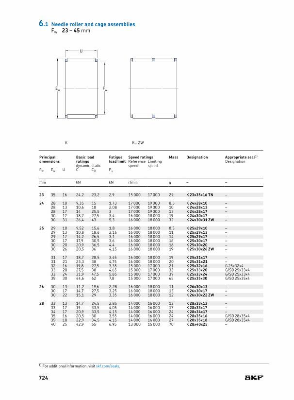
23 35 16 24,2 23,2 2,9 15 000 17 000 29 K 23x35x16 TN –
24 28 10 9,35 15 1,73 17 000 19 000 8,5 K 24x28x10 –28 13 10,6 18 2,08 17 000 19 000 10 K 24x28x13 –28 17 14 25,5 3 17 000 19 000 13 K 24x28x17 –30 17 18,7 27,5 3,4 16 000 18 000 19 K 24x30x17 –30 31 26,4 43 5,3 16 000 18 000 32 K 24x30x31 ZW –
25 29 10 9,52 15,6 1,8 16 000 18 000 8,5 K 25x29x10 –29 13 10,8 18,6 2,16 16 000 18 000 11 K 25x29x13 –29 17 14,2 26,5 3,1 16 000 18 000 14 K 25x29x17 –30 17 17,9 30,5 3,6 16 000 18 000 16 K 25x30x17 –30 20 20,9 36,5 4,4 16 000 18 000 18 K 25x30x20 –30 26 20,5 36 4,15 16 000 18 000 19 K 25x30x26 ZW –
31 17 18,7 28,5 3,45 16 000 18 000 19 K 25x31x17 –31 21 23,3 38 4,75 16 000 18 000 20 K 25x31x21 –32 16 19,8 27,5 3,35 15 000 17 000 21 K 25x32x16 G 25x32x433 20 27,5 38 4,65 15 000 17 000 33 K 25x33x20 G/SD 25x33x433 24 31,9 47,5 5,85 15 000 17 000 39 K 25x33x24 G/SD 25x33x435 30 44,6 62 7,8 15 000 17 000 65 K 25x35x30 G/SD 25x35x4
26 30 13 11,2 19,6 2,28 16 000 18 000 11 K 26x30x13 –30 17 14,7 27,5 3,25 16 000 18 000 15 K 26x30x17 –30 22 15,1 29 3,35 16 000 18 000 12 K 26x30x22 ZW –
28 33 13 14,7 24,5 2,85 14 000 16 000 13 K 28x33x13 –33 17 19 33,5 4,05 14 000 16 000 17 K 28x33x17 –34 17 20,9 33,5 4,15 14 000 16 000 24 K 28x34x17 –35 16 20,5 30 3,55 14 000 16 000 24 K 28x35x16 G/SD 28x35x435 18 22,9 34,5 4,15 14 000 16 000 27 K 28x35x18 G/SD 28x35x440 25 42,9 55 6,95 13 000 15 000 70 K 28x40x25 –
K K .. ZW
6.1 Needle roller and cage assembliesFw 23 – 45 mm
Principal dimensions
Basic load ratings
Fatigue load limit
Speed ratings Mass Designation Appropriate seal1)
Reference speed
Limiting speed
Designationdynamic static
Fw Ew U C C0 Pu
mm kN kN r/min g – –
FwEw
U
1) For additional information, visit skf.com/seals.
724

30 34 13 11,9 22 2,55 14 000 15 000 14 K 30x34x13 –35 13 15,1 25,5 3 13 000 15 000 14 K 30x35x13 –35 17 18,7 34 4,05 13 000 15 000 19 K 30x35x17 –35 27 29,2 60 7,35 13 000 15 000 30 K 30x35x27 –37 16 22 33,5 4 13 000 15 000 27 K 30x37x16 G/SD 30x37x437 18 25,1 39 4,65 13 000 15 000 30 K 30x37x18 G/SD 30x37x4
40 18 30,3 40 4,9 12 000 14 000 48 K 30x40x18 G/SD 30x40x440 30 46,8 69,5 8,65 12 000 14 000 73 K 30x40x30 G/SD 30x40x4
32 37 13 14,7 25,5 3 13 000 14 000 18 K 32x37x13 –37 17 19 35,5 4,25 13 000 14 000 19 K 32x37x17 –37 27 28,6 60 7,35 13 000 14 000 30 K 32x37x27 –38 20 25,1 45 5,6 12 000 14 000 30 K 32x38x20 –39 16 22,9 35,5 4,25 12 000 14 000 37 K 32x39x16 –39 18 25,5 41,5 5 12 000 14 000 31 K 32x39x18 –
40 25 35,8 58,5 7,2 12 000 14 000 49 K 32x40x25 –40 42 48,4 83 10,2 12 000 14 000 77 K 32x40x42 ZWTN –46 32 62,7 83 10,4 11 000 13 000 119 K 32x46x32 –
35 40 13 15,4 28 3,25 12 000 13 000 19 K 35x40x13 –40 17 19,8 39 4,65 12 000 13 000 21 K 35x40x17 –40 25 28,1 60 7,35 12 000 13 000 31 K 35x40x25 –40 27 23,8 49 6 12 000 13 000 39 K 35x40x27 TN –42 16 23,3 37,5 4,5 11 000 13 000 34 K 35x42x16 G/SD 35x42x442 18 26,4 44 5,3 11 000 13 000 34 K 35x42x18 G/SD 35x42x4
42 20 29,2 50 6 11 000 13 000 37 K 35x42x20 G/SD 35x42x442 30 37,4 68 8,5 11 000 13 000 67 K 35x42x30 G/SD 35x42x445 20 35,2 50 6,2 11 000 12 000 56 K 35x45x20 G/SD 35x45x445 30 50,1 80 10 11 000 12 000 80 K 35x45x30 G/SD 35x45x4
37 42 17 21,6 43 5,2 11 000 13 000 22 K 37x42x17 –
38 43 17 19,8 39 4,65 11 000 12 000 29 K 38x43x17 –43 27 30,3 68 8,3 11 000 12 000 43 K 38x43x27 –46 20 34,1 57 6,95 10 000 12 000 47 K 38x46x20 –46 32 52,3 100 12,5 10 000 12 000 76 K 38x46x32 –
39 44 26 26 57 6,7 10 000 12 000 45 K 39x44x26 ZW –
40 45 13 16,8 32,5 3,8 10 000 12 000 18 K 40x45x13 –45 17 20,5 41,5 5 10 000 12 000 31 K 40x45x17 –45 27 31,4 73,5 9 10 000 12 000 46 K 40x45x27 –47 18 28,6 50 6,1 10 000 11 000 39 K 40x47x18 G/SD 40x47x447 20 31,4 57 6,95 10 000 11 000 42 K 40x47x20 G/SD 40x47x448 20 34,7 58,5 7,35 10 000 11 000 49 K 40x48x20 –
42 47 13 17,2 33,5 4 10 000 11 000 18 K 42x47x13 –47 17 20,9 43 5,2 10 000 11 000 32 K 42x47x17 –47 30 31,9 76,5 9 10 000 11 000 54 K 42x47x30 ZW –50 20 33,6 57 7,1 9 500 11 000 53 K 42x50x20 –
43 48 17 20,9 43 5,2 9 500 11 000 30 K 43x48x17 –48 27 31,9 76,5 9,3 9 500 11 000 50 K 43x48x27 –
45 50 17 21,6 46,5 5,6 9 000 10 000 34 K 45x50x17 –50 27 33 81,5 10 9 000 10 000 52 K 45x50x27 –52 18 30,3 57 6,95 9 000 10 000 42 K 45x52x18 G/SD 45x52x453 20 37,4 68 8,3 9 000 10 000 55 K 45x53x20 –53 21 36,9 67 8,3 9 000 10 000 60 K 45x53x21 –53 28 49,5 98 12,2 9 000 10 000 81 K 45x53x28 –
59 18 44 53 6,55 8 500 9 500 72 K 45x59x18 TN –59 32 69,3 102 12,9 8 500 9 500 148 K 45x59x32 –
6 .1
Principal dimensions
Basic load ratings
Fatigue load limit
Speed ratings Mass Designation Appropriate seal1)
Reference speed
Limiting speed
Designationdynamic static
Fw Ew U C C0 Pu
mm kN kN r/min g – –
1) For additional information, visit skf.com/seals.
725

47 52 17 22,4 49 6 9 000 10 000 35 K 47x52x17 –52 27 33,6 83 10,2 9 000 10 000 51 K 47x52x27 –
50 55 13,5 17,6 36,5 4,3 8 500 9 500 30 K 50x55x13.5 –55 17 23,8 55 6,55 8 500 9 500 35 K 50x55x17 –55 20 25,5 60 7,2 8 500 9 500 43 K 50x55x20 –55 30 37,4 98 12 8 500 9 500 65 K 50x55x30 –57 18 31,9 64 7,8 8 000 9 000 47 K 50x57x18 –
58 20 34,1 62 7,65 8 000 9 000 75 K 50x58x20 G/SD 50x58x458 25 41,8 81,5 10,2 8 000 9 000 90 K 50x58x25 G/SD 50x58x4
52 57 12 17,2 36,5 4,3 8 000 9 000 24 K 52x57x12 –
55 60 20 27 67 8,15 7 500 8 500 40 K 55x60x20 –60 27 35,8 96,5 12 7 500 8 500 60 K 55x60x27 –60 30 39,6 108 13,4 7 500 8 500 71 K 55x60x30 –62 18 34,1 71 8,5 7 500 8 500 52 K 55x62x18 –
63 20 38 75 9,15 7 500 8 500 67 K 55x63x20 G 55x63x563 25 49,5 104 12,9 7 500 8 500 80 K 55x63x25 G 55x63x563 32 59,4 129 16,3 7 500 8 500 102 K 55x63x32 G 55x63x5
58 65 18 33,6 71 8,65 7 000 8 000 52 K 58x65x18 –65 36 47,3 108 12,9 7 000 8 000 127 K 58x65x36 ZW –
60 65 20 28,1 72 8,8 7 000 8 000 52 K 60x65x20 –65 30 41,3 116 14,3 7 000 8 000 77 K 60x65x30 –66 33 44 112 13,7 7 000 8 000 104 K 60x66x33 ZW –66 40 55 150 18,6 7 000 8 000 116 K 60x66x40 ZW –
68 20 41,8 86,5 10,6 6 700 7 500 71 K 60x68x20 –68 23 47,3 102 12,5 6 700 7 500 94 K 60x68x23 –68 25 51,2 112 14 6 700 7 500 89 K 60x68x25 –68 30 42,9 88 10,6 6 700 7 500 129 K 60x68x30 ZW –75 42 112 196 25 6 300 7 500 240 K 60x75x42 –
62 70 40 62,7 146 18 6 700 7 500 174 K 62x70x40 ZW –
K K .. ZW
6.1 Needle roller and cage assembliesFw 47 – 155 mm
Principal dimensions
Basic load ratings
Fatigue load limit
Speed ratings Mass Designation Appropriate seal1)
Reference speed
Limiting speed
Designationdynamic static
Fw Ew U C C0 Pu
mm kN kN r/min g – –
FwEw
U
1) For additional information, visit skf.com/seals.
726

64 70 16 26,4 60 7,35 6 300 7 500 53 K 64x70x16 –
65 70 20 29,2 76,5 9,3 6 300 7 500 56 K 65x70x20 –70 30 41,8 125 15,3 6 300 7 500 83 K 65x70x30 –73 23 44 95 11,6 6 300 7 000 108 K 65x73x23 –73 30 53,9 125 15,6 6 300 7 000 141 K 65x73x30 –
68 74 20 33,6 83 10,4 6 000 7 000 71 K 68x74x20 –74 30 44,6 118 15 6 000 7 000 100 K 68x74x30 –74 35 46,8 125 15,3 6 000 7 000 120 K 68x74x35 ZW –
70 76 20 34,1 86,5 10,6 6 000 6 700 71 K 70x76x20 –76 30 50,1 140 17,6 6 000 6 700 110 K 70x76x30 –78 30 57,2 137 17 6 000 6 700 148 K 70x78x30 G 70x78x5
72 80 20 39,6 85 10,6 5 600 6 300 98 K 72x80x20 –
73 79 20 35,2 90 11,2 5 600 6 300 75 K 73x79x20 –
75 81 20 35,8 93 11,6 5 600 6 300 79 K 75x81x20 –81 30 50,1 143 18 5 600 6 300 114 K 75x81x30 –83 23 47,3 110 13,7 5 300 6 300 124 K 75x83x23 –83 30 59,4 143 18 5 300 6 300 147 K 75x83x30 –83 35 60,5 146 18 5 300 6 300 182 K 75x83x35 ZW –83 40 69,3 176 22 5 300 6 300 211 K 75x83x40 ZW –
80 86 20 36,9 98 12,2 5 300 6 000 60 K 80x86x20 –88 30 68,2 176 22 5 000 6 000 138 K 80x88x30 –88 40 72,1 193 23,6 5 000 6 000 227 K 80x88x40 ZW –88 46 84,2 232 28,5 5 000 6 000 260 K 80x88x46 ZW –
85 92 20 42,9 108 13,2 4 800 5 600 102 K 85x92x20 –
90 97 20 42,9 114 13,7 4 500 5 300 109 K 90x97x20 –98 27 58,3 150 18,6 4 500 5 300 150 K 90x98x27 –98 30 64,4 173 21,6 4 500 5 300 172 K 90x98x30 –
95 103 30 66 180 22,8 4 300 5 000 165 K 95x103x30 –103 40 79,2 228 28,5 4 300 5 000 266 K 95x103x40 ZW –
100 107 21 45,7 127 15,3 4 000 4 800 120 K 100x107x21 –108 27 55 143 17,6 4 000 4 800 185 K 100x108x27 –108 30 67,1 190 23,6 4 000 4 800 180 K 100x108x30 –
105 112 21 45,7 129 15,3 4 000 4 500 129 K 105x112x21 –
110 117 24 53,9 160 18,6 3 800 4 300 172 K 110x117x24 –118 30 73,7 220 26,5 3 800 4 300 217 K 110x118x30 –
115 123 27 60,5 170 20 3 600 4 000 200 K 115x123x27 –
120 127 24 56,1 176 20,4 3 400 4 000 165 K 120x127x24 –
125 133 35 82,5 260 30,5 3 200 3 800 275 K 125x133x35 –
130 137 24 58,3 186 21,2 3 200 3 600 170 K 130x137x24 –
135 143 35 88 290 33,5 3 000 3 400 300 K 135x143x35 –
145 153 26 70,4 224 25 2 800 3 200 262 K 145x153x26 –
150 160 46 140 475 53 2 800 3 000 570 K 150x160x46 –
155 163 26 72,1 236 25,5 2 600 3 000 265 K 155x163x26 –
6 .1
Principal dimensions
Basic load ratings
Fatigue load limit
Speed ratings Mass Designation Appropriate seal1)
Reference speed
Limiting speed
Designationdynamic static
Fw Ew U C C0 Pu
mm kN kN r/min g – –
1) For additional information, visit skf.com/seals.
727

160 170 46 145 510 56 2 600 2 800 550 K 160x170x46
165 173 26 76,5 265 28,5 2 400 2 800 320 K 165x173x26
175 183 32 95,2 355 37,5 2 400 2 600 400 K 175x183x32
185 195 37 123 425 45 2 200 2 400 607 K 185x195x37
195 205 37 125 450 46,5 2 000 2 400 620 K 195x205x37
210 220 42 147 560 57 1 900 2 200 740 K 210x220x42
220 230 42 151 585 58,5 1 800 2 000 790 K 220x230x42
240 250 42 157 630 62 1 700 1 900 850 K 240x250x42
265 280 50 242 850 83 1 500 1 700 1 810 K 265x280x50
6.1 Needle roller and cage assembliesFw 160 – 265 mm
Principal dimensions
Basic load ratings
Fatigue load limit
Speed ratings Mass DesignationReference speed
Limiting speeddynamic static
Fw Ew U C C0 Pu
mm kN kN r/min g –
FwEw
U
728

6 .1
729
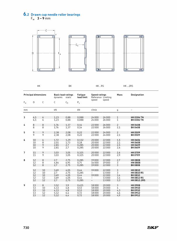
3 6,5 6 1,23 0,88 0,088 24 000 26 000 1 HK 0306 TN 3 – 0,3 – –6,5 6 1,23 0,88 0,088 24 000 26 000 1 BK 0306 TN 5,2 0,3 – –
4 8 8 1,76 1,37 0,14 22 000 26 000 2 HK 0408 4 – 0,4 – G 4x8x2 S8 8 1,76 1,37 0,14 22 000 26 000 2,1 BK 0408 6,4 0,3 – G 4x8x2 S
5 9 9 2,38 2,08 0,22 22 000 24 000 2 HK 0509 5 – 0,4 – G 5x9x2 S9 9 2,38 2,08 0,22 22 000 24 000 2,1 BK 0509 7,4 0,4 – G 5x9x2 S
6 10 6 1,72 1,29 0,132 20 000 22 000 1,5 HK 0606 6 – 0,4 – G 6x10x2 S10 8 2,01 1,73 0,18 20 000 22 000 2,1 HK 0608 – 0,4 – G 6x10x2 S10 9 2,81 2,7 0,285 20 000 22 000 2,5 HK 0609 – 0,4 – G 6x10x2 S10 9 2,81 2,7 0,285 20 000 22 000 2,6 BK 0609 7,4 0,4 – G 6x10x2 S
7 11 9 3,03 3,05 0,325 20 000 22 000 2,6 HK 0709 7 – 0,4 – G 7x11x2 S11 9 3,03 3,05 0,325 20 000 22 000 2,9 BK 0709 7,4 0,4 – G 7x11x2 S
8 12 8 2,7 2,75 0,285 19 000 22 000 2,7 HK 0808 8 – 0,4 – G 8x12x312 8 4,84 6,95 0,75 16 000 19 000 3 HN 0808 – 0,4 – –12 8 2,7 2,75 0,285 19 000 22 000 3 BK 0808 6,4 0,4 – G 8x12x3
12 10 3,69 4,05 0,44 19 000 22 000 3 HK 0810 – 0,4 IR 5x8x12 G 8x12x312 10 2,7 2,75 0,285 – 13 000 3 HK 0810 RS – 0,4 – –12 10 3,69 4,05 0,44 19 000 22 000 3,4 BK 0810 8,4 0,4 IR 5x8x12 G 8x12x312 12 3,69 4,05 0,44 – 13 000 3,1 HK 0812 RS – 0,4 – –12 12 2,7 2,75 0,285 – 13 000 3,3 HK 0812.2RS – 0,4 – –
9 13 8 3,52 3,9 0,415 18 000 20 000 3 HK 0908 9 – 0,4 – G 9x13x313 10 4,13 4,8 0,53 18 000 20 000 4 HK 0910 – 0,4 – G 9x13x313 10 4,13 4,8 0,53 18 000 20 000 4,3 BK 0910 8,4 0,4 – G 9x13x313 12 5,12 6,4 0,72 18 000 20 000 4,6 HK 0912 – 0,4 IR 6x9x12 G 9x13x313 12 5,12 6,4 0,72 18 000 20 000 4,9 BK 0912 10,4 0,4 IR 6x9x12 G 9x13x3
C1
Fw
C
D
r
6.2 Drawn cup needle roller bearingsFw 3 – 9 mm
Principal dimensions Basic load ratings Fatigue
load limitSpeed ratings Mass Designation Dimensions Appropriate inner ring1) Appropriate seal2)
dynamic static Reference speed
Limiting speed
Designation Designation
Fw D C C C0 Pu Fw C1 rmin. min.
mm kN kN r/min g – mm – –
HK BK HK .. RS HK ...2RS
730

3 6,5 6 1,23 0,88 0,088 24 000 26 000 1 HK 0306 TN 3 – 0,3 – –6,5 6 1,23 0,88 0,088 24 000 26 000 1 BK 0306 TN 5,2 0,3 – –
4 8 8 1,76 1,37 0,14 22 000 26 000 2 HK 0408 4 – 0,4 – G 4x8x2 S8 8 1,76 1,37 0,14 22 000 26 000 2,1 BK 0408 6,4 0,3 – G 4x8x2 S
5 9 9 2,38 2,08 0,22 22 000 24 000 2 HK 0509 5 – 0,4 – G 5x9x2 S9 9 2,38 2,08 0,22 22 000 24 000 2,1 BK 0509 7,4 0,4 – G 5x9x2 S
6 10 6 1,72 1,29 0,132 20 000 22 000 1,5 HK 0606 6 – 0,4 – G 6x10x2 S10 8 2,01 1,73 0,18 20 000 22 000 2,1 HK 0608 – 0,4 – G 6x10x2 S10 9 2,81 2,7 0,285 20 000 22 000 2,5 HK 0609 – 0,4 – G 6x10x2 S10 9 2,81 2,7 0,285 20 000 22 000 2,6 BK 0609 7,4 0,4 – G 6x10x2 S
7 11 9 3,03 3,05 0,325 20 000 22 000 2,6 HK 0709 7 – 0,4 – G 7x11x2 S11 9 3,03 3,05 0,325 20 000 22 000 2,9 BK 0709 7,4 0,4 – G 7x11x2 S
8 12 8 2,7 2,75 0,285 19 000 22 000 2,7 HK 0808 8 – 0,4 – G 8x12x312 8 4,84 6,95 0,75 16 000 19 000 3 HN 0808 – 0,4 – –12 8 2,7 2,75 0,285 19 000 22 000 3 BK 0808 6,4 0,4 – G 8x12x3
12 10 3,69 4,05 0,44 19 000 22 000 3 HK 0810 – 0,4 IR 5x8x12 G 8x12x312 10 2,7 2,75 0,285 – 13 000 3 HK 0810 RS – 0,4 – –12 10 3,69 4,05 0,44 19 000 22 000 3,4 BK 0810 8,4 0,4 IR 5x8x12 G 8x12x312 12 3,69 4,05 0,44 – 13 000 3,1 HK 0812 RS – 0,4 – –12 12 2,7 2,75 0,285 – 13 000 3,3 HK 0812.2RS – 0,4 – –
9 13 8 3,52 3,9 0,415 18 000 20 000 3 HK 0908 9 – 0,4 – G 9x13x313 10 4,13 4,8 0,53 18 000 20 000 4 HK 0910 – 0,4 – G 9x13x313 10 4,13 4,8 0,53 18 000 20 000 4,3 BK 0910 8,4 0,4 – G 9x13x313 12 5,12 6,4 0,72 18 000 20 000 4,6 HK 0912 – 0,4 IR 6x9x12 G 9x13x313 12 5,12 6,4 0,72 18 000 20 000 4,9 BK 0912 10,4 0,4 IR 6x9x12 G 9x13x3
6 .2
Principal dimensions Basic load ratings Fatigue
load limitSpeed ratings Mass Designation Dimensions Appropriate inner ring1) Appropriate seal2)
dynamic static Reference speed
Limiting speed
Designation Designation
Fw D C C C0 Pu Fw C1 rmin. min.
mm kN kN r/min g – mm – –
1) For additional information, refer to Needle roller bearing inner rings († page 691).2) For additional information, visit skf.com/seals.
731

10 14 10 4,29 5,3 0,57 18 000 20 000 4,1 HK 1010 10 – 0,4 LR/IR 7x10x10.5 G 10x14x314 10 6,82 11,4 1,27 14 000 18 000 4,6 HN 1010 – 0,4 LR/IR 7x10x10.5 G 10x14x314 10 4,29 5,3 0,57 18 000 20 000 4,3 BK 1010 8,4 0,4 LR/IR 7x10x10.5 G 10x14x3
14 12 5,39 6,95 0,78 18 000 20 000 4,8 HK 1012 – 0,4 IR 7x10x12 G 10x14x314 12 4,29 5,3 0,57 – 12 000 4,2 HK 1012 RS – 0,4 – –14 12 3,19 3,55 0,365 – 12 000 4,3 HK 1012.2RS – 0,4 – –14 12 5,39 6,95 0,78 18 000 20 000 5 BK 1012 10,4 0,4 IR 7x10x12 G 10x14x314 12 4,29 5,3 0,57 – 12 000 4,3 BK 1012 RS 10,4 0,4 – –
14 14 4,29 5,3 0,57 – 12 000 4,6 HK 1014.2RS – 0,4 – –14 15 6,6 9 1,02 18 000 20 000 6 HK 1015 – 0,4 IR 7x10x16 G 10x14x314 15 6,6 9 1,02 18 000 20 000 6,2 BK 1015 13,4 0,4 IR 7x10x16 G 10x14x3
12 16 10 4,84 6,4 0,71 16 000 18 000 4,6 HK 1210 12 – 0,4 LR/IR 8x12x10.5 G 12x16x316 10 7,48 13,7 1,53 13 000 17 000 5,3 HN 1210 – 0,4 LR/IR 8x12x10.5 G 12x16x316 10 4,84 6,4 0,71 16 000 18 000 5,2 BK 1210 8,4 0,4 LR/IR 8x12x10.5 G 12x16x318 12 6,27 7,35 0,85 16 000 18 000 9 HK 1212 – 0,8 LR/IR 8x12x12.5 G/SD 12x18x318 12 9,52 15,3 1,76 13 000 17 000 10,5 HN 1212 – 0,8 LR/IR 8x12x12.5 G/SD 12x18x318 12 6,27 7,35 0,85 16 000 18 000 10 BK 1212 9,3 0,8 LR/IR 8x12x12.5 G/SD 12x18x3
18 14 6,27 7,35 0,85 – 10 000 10 HK 1214 RS – 0,8 – –16 14 4,84 6,4 0,71 – 10 000 8 HK 1214.2RS – 0,4 – –18 16 6,27 7,35 0,85 – 10 000 11 HK 1216.2RS – 0,8 – –
–13 19 12 6,6 8 0,915 16 000 17 000 10 HK 1312 13 – 0,8 LR/IR 10x13x12.5 G 13x19x3
19 12 6,6 8 0,915 16 000 17 000 11 BK 1312 9,3 0,8 LR/IR 10x13x12.5 G 13x19x3
14 20 12 6,82 8,65 0,98 15 000 17 000 10,5 HK 1412 14 – 0,8 IR 10x14x13 G/SD 14x20x320 12 10,5 17,6 2,04 12 000 15 000 12 HN 1412 – 0,8 IR 10x14x13 G/SD 14x20x320 12 6,82 8,65 0,98 15 000 17 000 12 BK 1412 9,3 0,8 IR 10x14x13 G/SD 14x20x320 14 6,82 8,65 0,98 – 9 500 12 HK 1414 RS – 0,8 – –20 14 6,82 8,65 0,98 – 9 500 13 BK 1414 RS 11,3 0,8 – –20 16 6,82 8,65 0,98 – 9 500 13 HK 1416.2RS – 0,8 – –
6.2 Drawn cup needle roller bearingsFw 10 – 14 mm
Principal dimensions Basic load ratings Fatigue
load limitSpeed ratings Mass Designation Dimensions Appropriate inner ring1) Appropriate seal2)
dynamic static Reference speed
Limiting speed
Designation Designation
Fw D C C C0 Pu Fw C1 rmin. min.
mm kN kN r/min g – mm – –
C1
Fw
C
D
r
HK BK HK .. RS HK ...2RS
732
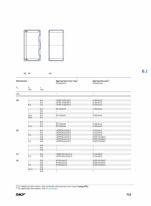
10 14 10 4,29 5,3 0,57 18 000 20 000 4,1 HK 1010 10 – 0,4 LR/IR 7x10x10.5 G 10x14x314 10 6,82 11,4 1,27 14 000 18 000 4,6 HN 1010 – 0,4 LR/IR 7x10x10.5 G 10x14x314 10 4,29 5,3 0,57 18 000 20 000 4,3 BK 1010 8,4 0,4 LR/IR 7x10x10.5 G 10x14x3
14 12 5,39 6,95 0,78 18 000 20 000 4,8 HK 1012 – 0,4 IR 7x10x12 G 10x14x314 12 4,29 5,3 0,57 – 12 000 4,2 HK 1012 RS – 0,4 – –14 12 3,19 3,55 0,365 – 12 000 4,3 HK 1012.2RS – 0,4 – –14 12 5,39 6,95 0,78 18 000 20 000 5 BK 1012 10,4 0,4 IR 7x10x12 G 10x14x314 12 4,29 5,3 0,57 – 12 000 4,3 BK 1012 RS 10,4 0,4 – –
14 14 4,29 5,3 0,57 – 12 000 4,6 HK 1014.2RS – 0,4 – –14 15 6,6 9 1,02 18 000 20 000 6 HK 1015 – 0,4 IR 7x10x16 G 10x14x314 15 6,6 9 1,02 18 000 20 000 6,2 BK 1015 13,4 0,4 IR 7x10x16 G 10x14x3
12 16 10 4,84 6,4 0,71 16 000 18 000 4,6 HK 1210 12 – 0,4 LR/IR 8x12x10.5 G 12x16x316 10 7,48 13,7 1,53 13 000 17 000 5,3 HN 1210 – 0,4 LR/IR 8x12x10.5 G 12x16x316 10 4,84 6,4 0,71 16 000 18 000 5,2 BK 1210 8,4 0,4 LR/IR 8x12x10.5 G 12x16x318 12 6,27 7,35 0,85 16 000 18 000 9 HK 1212 – 0,8 LR/IR 8x12x12.5 G/SD 12x18x318 12 9,52 15,3 1,76 13 000 17 000 10,5 HN 1212 – 0,8 LR/IR 8x12x12.5 G/SD 12x18x318 12 6,27 7,35 0,85 16 000 18 000 10 BK 1212 9,3 0,8 LR/IR 8x12x12.5 G/SD 12x18x3
18 14 6,27 7,35 0,85 – 10 000 10 HK 1214 RS – 0,8 – –16 14 4,84 6,4 0,71 – 10 000 8 HK 1214.2RS – 0,4 – –18 16 6,27 7,35 0,85 – 10 000 11 HK 1216.2RS – 0,8 – –
–13 19 12 6,6 8 0,915 16 000 17 000 10 HK 1312 13 – 0,8 LR/IR 10x13x12.5 G 13x19x3
19 12 6,6 8 0,915 16 000 17 000 11 BK 1312 9,3 0,8 LR/IR 10x13x12.5 G 13x19x3
14 20 12 6,82 8,65 0,98 15 000 17 000 10,5 HK 1412 14 – 0,8 IR 10x14x13 G/SD 14x20x320 12 10,5 17,6 2,04 12 000 15 000 12 HN 1412 – 0,8 IR 10x14x13 G/SD 14x20x320 12 6,82 8,65 0,98 15 000 17 000 12 BK 1412 9,3 0,8 IR 10x14x13 G/SD 14x20x320 14 6,82 8,65 0,98 – 9 500 12 HK 1414 RS – 0,8 – –20 14 6,82 8,65 0,98 – 9 500 13 BK 1414 RS 11,3 0,8 – –20 16 6,82 8,65 0,98 – 9 500 13 HK 1416.2RS – 0,8 – –
6 .2
Principal dimensions Basic load ratings Fatigue
load limitSpeed ratings Mass Designation Dimensions Appropriate inner ring1) Appropriate seal2)
dynamic static Reference speed
Limiting speed
Designation Designation
Fw D C C C0 Pu Fw C1 rmin. min.
mm kN kN r/min g – mm – –
1) For additional information, refer to Needle roller bearing inner rings († page 691).2) For additional information, visit skf.com/seals.
BK .. RS HN
733

15 21 12 7,65 9,5 1,08 15 000 16 000 11 HK 1512 15 – 0,8 LR/IR 12x15x12.5 G/SD 15x21x321 12 7,65 9,5 1,08 15 000 16 000 13 BK 1512 9,3 0,8 LR/IR 12x15x12.5 G/SD 15x21x321 14 7,48 10 1,14 – 9 500 12 HK 1514 RS – 0,8 LR/IR 12x15x16.5 –21 14 7,48 10 1,14 – 9 500 14 BK 1514 RS 11,3 0,8 LR/IR 12x15x16.5 –
21 16 10,1 14,6 1,7 15 000 16 000 15 HK 1516 – 0,8 LR/IR 12x15x16.5 G/SD 15x21x321 16 7,48 10 1,14 – 9 500 15 HK 1516.2RS – 0,8 LR/IR 12x15x16.5 –21 16 14,5 28 3,25 12 000 15 000 14 HN 1516 – 0,8 LR/IR 12x15x16.5 G/SD 15x21x321 16 10,1 14,6 1,7 15 000 16 000 17 BK 1516 13,3 0,8 LR/IR 12x15x16.5 G/SD 15x21x3
21 18 10,1 14,6 1,7 – 9 500 16 HK 1518 RS – 0,8 – –21 20 10,1 14,6 1,7 – 9 500 18 HK 1520.2RS – 0,8 – –21 22 13 20 2,28 15 000 16 000 20 HK 1522 – 0,8 LR/IR 12x15x22.5 G/SD 15x21x3
16 22 12 7,37 9,8 1,12 14 000 16 000 12 HK 1612 16 – 0,8 IR 12x16x13 G/SD 16x22x322 12 11,2 20,4 2,32 12 000 15 000 13 HN 1612 – 0,8 IR 12x16x13 G/SD 16x22x322 12 7,37 9,8 1,12 14 000 16 000 14 BK 1612 9,3 0,8 IR 12x16x13 G/SD 16x22x322 14 7,37 9,8 1,12 – 9 000 13 HK 1614 RS – 0,8 IR 12x16x20 –22 14 7,37 9,8 1,12 – 9 000 15 BK 1614 RS 11,3 0,8 IR 12x16x20 –
22 16 10,5 15,6 1,8 14 000 16 000 16 HK 1616 – 0,8 IR 12x16x16 G/SD 16x22x322 16 7,37 9,8 1,12 – 9 000 14 HK 1616.2RS – 0,8 IR 12x16x20 –22 16 10,5 15,6 1,8 14 000 16 000 18 BK 1616 13,3 0,8 IR 12x16x16 G/SD 16x22x322 20 10,5 15,6 1,8 – 9 000 18 HK 1620.2RS – 0,8 – –22 22 12,8 19,6 2,24 14 000 16 000 24 HK 16221) – 0,8 IR 12x16x22 G/SD 16x22x322 22 12,8 19,6 2,24 14 000 16 000 24 BK 16221) 19,3 0,8 IR 12x16x22 G/SD 16x22x3
17 23 12 7,65 10,6 1,2 14 000 15 000 12 HK 1712 17 – 0,8 – G/SD 17x23x3
18 24 12 7,92 11,2 1,27 13 000 15 000 13 HK 1812 18 – 0,8 LR 15x18x12.5 G/SD 18x24x324 12 7,92 11,2 1,27 13 000 15 000 15 BK 1812 9,3 0,8 LR 15x18x12.5 G/SD 18x24x324 14 7,92 11,2 1,27 – 8 500 14 HK 1814 RS – 0,8 LR/IR 15x18x16.5 –
24 16 11,2 17,6 2,04 13 000 15 000 18 HK 1816 – 0,8 LR/IR 15x18x16.5 G/SD 18x24x324 16 7,92 11,2 1,27 – 8 500 15 HK 1816.2RS – 0,8 LR/IR 15x18x16.5 –24 16 16,1 33,5 3,8 11 000 14 000 20 HN 1816 – 0,8 LR/IR 15x18x16.5 G/SD 18x24x324 16 11,2 17,6 2,04 13 000 15 000 20 BK 1816 13,3 0,8 LR/IR 15x18x16.5 G/SD 18x24x3
6.2 Drawn cup needle roller bearingsFw 15 – 18 mm
Principal dimensions Basic load ratings Fatigue
load limitSpeed ratings Mass Designation Dimensions Appropriate inner ring1) Appropriate seal2)
dynamic static Reference speed
Limiting speed
Designation Designation
Fw D C C C0 Pu Fw C1 rmin. min.
mm kN kN r/min g – mm – –
1) Double row, outer ring with a lubrication hole
C1
Fw
C
D
r
HK BK HK .. RS HK ...2RS
734

15 21 12 7,65 9,5 1,08 15 000 16 000 11 HK 1512 15 – 0,8 LR/IR 12x15x12.5 G/SD 15x21x321 12 7,65 9,5 1,08 15 000 16 000 13 BK 1512 9,3 0,8 LR/IR 12x15x12.5 G/SD 15x21x321 14 7,48 10 1,14 – 9 500 12 HK 1514 RS – 0,8 LR/IR 12x15x16.5 –21 14 7,48 10 1,14 – 9 500 14 BK 1514 RS 11,3 0,8 LR/IR 12x15x16.5 –
21 16 10,1 14,6 1,7 15 000 16 000 15 HK 1516 – 0,8 LR/IR 12x15x16.5 G/SD 15x21x321 16 7,48 10 1,14 – 9 500 15 HK 1516.2RS – 0,8 LR/IR 12x15x16.5 –21 16 14,5 28 3,25 12 000 15 000 14 HN 1516 – 0,8 LR/IR 12x15x16.5 G/SD 15x21x321 16 10,1 14,6 1,7 15 000 16 000 17 BK 1516 13,3 0,8 LR/IR 12x15x16.5 G/SD 15x21x3
21 18 10,1 14,6 1,7 – 9 500 16 HK 1518 RS – 0,8 – –21 20 10,1 14,6 1,7 – 9 500 18 HK 1520.2RS – 0,8 – –21 22 13 20 2,28 15 000 16 000 20 HK 1522 – 0,8 LR/IR 12x15x22.5 G/SD 15x21x3
16 22 12 7,37 9,8 1,12 14 000 16 000 12 HK 1612 16 – 0,8 IR 12x16x13 G/SD 16x22x322 12 11,2 20,4 2,32 12 000 15 000 13 HN 1612 – 0,8 IR 12x16x13 G/SD 16x22x322 12 7,37 9,8 1,12 14 000 16 000 14 BK 1612 9,3 0,8 IR 12x16x13 G/SD 16x22x322 14 7,37 9,8 1,12 – 9 000 13 HK 1614 RS – 0,8 IR 12x16x20 –22 14 7,37 9,8 1,12 – 9 000 15 BK 1614 RS 11,3 0,8 IR 12x16x20 –
22 16 10,5 15,6 1,8 14 000 16 000 16 HK 1616 – 0,8 IR 12x16x16 G/SD 16x22x322 16 7,37 9,8 1,12 – 9 000 14 HK 1616.2RS – 0,8 IR 12x16x20 –22 16 10,5 15,6 1,8 14 000 16 000 18 BK 1616 13,3 0,8 IR 12x16x16 G/SD 16x22x322 20 10,5 15,6 1,8 – 9 000 18 HK 1620.2RS – 0,8 – –22 22 12,8 19,6 2,24 14 000 16 000 24 HK 16221) – 0,8 IR 12x16x22 G/SD 16x22x322 22 12,8 19,6 2,24 14 000 16 000 24 BK 16221) 19,3 0,8 IR 12x16x22 G/SD 16x22x3
17 23 12 7,65 10,6 1,2 14 000 15 000 12 HK 1712 17 – 0,8 – G/SD 17x23x3
18 24 12 7,92 11,2 1,27 13 000 15 000 13 HK 1812 18 – 0,8 LR 15x18x12.5 G/SD 18x24x324 12 7,92 11,2 1,27 13 000 15 000 15 BK 1812 9,3 0,8 LR 15x18x12.5 G/SD 18x24x324 14 7,92 11,2 1,27 – 8 500 14 HK 1814 RS – 0,8 LR/IR 15x18x16.5 –
24 16 11,2 17,6 2,04 13 000 15 000 18 HK 1816 – 0,8 LR/IR 15x18x16.5 G/SD 18x24x324 16 7,92 11,2 1,27 – 8 500 15 HK 1816.2RS – 0,8 LR/IR 15x18x16.5 –24 16 16,1 33,5 3,8 11 000 14 000 20 HN 1816 – 0,8 LR/IR 15x18x16.5 G/SD 18x24x324 16 11,2 17,6 2,04 13 000 15 000 20 BK 1816 13,3 0,8 LR/IR 15x18x16.5 G/SD 18x24x3
6 .2
Principal dimensions Basic load ratings Fatigue
load limitSpeed ratings Mass Designation Dimensions Appropriate inner ring1) Appropriate seal2)
dynamic static Reference speed
Limiting speed
Designation Designation
Fw D C C C0 Pu Fw C1 rmin. min.
mm kN kN r/min g – mm – –
1) For additional information, refer to Needle roller bearing inner rings († page 691).2) For additional information, visit skf.com/seals.
BK .. RS HN HK BK (double row) (double row)
735

20 26 10 6,16 8,5 0,93 12 000 14 000 12 HK 2010 20 – 0,8 – G/SD 20x26x426 12 8,42 12,5 1,4 12 000 14 000 14 HK 2012 – 0,8 IR 15x20x13 G/SD 20x26x4
26 16 12,3 20,4 2,36 12 000 14 000 19 HK 2016 – 0,8 LR/IR 17x20x16.5 G/SD 20x26x426 16 8,42 12,5 1,4 – 8 000 18 HK 2016.2RS – 0,8 LR/IR 17x20x16.5 –26 16 16,8 36,5 4,25 10 000 12 000 22 HN 2016 – 0,8 LR/IR 17x20x16.5 G/SD 20x26x426 16 12,3 20,4 2,36 12 000 14 000 22 BK 2016 13,3 0,8 LR/IR 17x20x16.5 G/SD 20x26x426 18 12,3 20,4 2,36 – 8 000 21 HK 2018 RS – 0,8 LR/IR 17x20x20.5 –26 18 12,3 20,4 2,36 – 8 000 24 BK 2018 RS 15,3 0,8 LR/IR 17x20x20.5 –
26 20 15,1 26,5 3,15 12 000 14 000 24 HK 2020 – 0,8 LR/IR 17x20x20.5 G/SD 20x26x426 20 12,3 20,4 2,36 – 8 000 23 HK 2020.2RS – 0,8 LR/IR 17x20x20.5 –26 20 20,9 48 5,7 10 000 12 000 29,5 HN 2020 – 0,8 LR/IR 17x20x20.5 G/SD 20x26x426 20 15,1 26,5 3,15 12 000 14 000 27 BK 2020 17,3 0,8 LR/IR 17x20x20.5 G/SD 20x26x426 30 20,9 40,5 4,75 12 000 14 000 35 HK 20301) – 0,8 LR/IR 17x20x30.5 G/SD 20x26x4
22 28 10 7,21 10,6 1,2 11 000 12 000 13 HK 2210 22 – 0,8 – G/SD 22x28x428 12 8,8 13,7 1,56 11 000 12 000 15 HK 2212 – 0,8 IR 17x22x13 G/SD 22x28x428 12 8,8 13,7 1,56 11 000 12 000 18 BK 2212 9,3 0,8 IR 17x22x13 G/SD 22x28x428 14 8,8 13,7 1,56 – 7 500 16 HK 2214 RS – 0,8 IR 17x22x23 –
28 16 13 22,4 2,6 11 000 12 000 21 HK 2216 – 0,8 IR 17x22x23 G/SD 22x28x428 16 8,8 13,7 1,56 – 7 500 18 HK 2216.2RS – 0,8 IR 17x22x23 –28 16 13 22,4 2,6 11 000 12 000 24 BK 2216 13,3 0,8 IR 17x22x16 G/SD 22x28x428 18 13 22,4 2,6 – 7 500 24 HK 2218 RS – 0,8 IR 17x22x23 –28 20 15,7 29 3,45 11 000 12 000 26 HK 2220 – 0,8 IR 17x22x23 G/SD 22x28x428 20 13 22,4 2,6 – 7 500 23 HK 2220.2RS – 0,8 IR 17x22x23 –
6.2 Drawn cup needle roller bearingsFw 20 – 22 mm
Principal dimensions Basic load ratings Fatigue
load limitSpeed ratings Mass Designation Dimensions Appropriate inner ring1) Appropriate seal2)
dynamic static Reference speed
Limiting speed
Designation Designation
Fw D C C C0 Pu Fw C1 rmin. min.
mm kN kN r/min g – mm – –
1) Double row, outer ring with a lubrication hole
C1
Fw
C
D
r
HK BK HK .. RS HK ...2RS
736
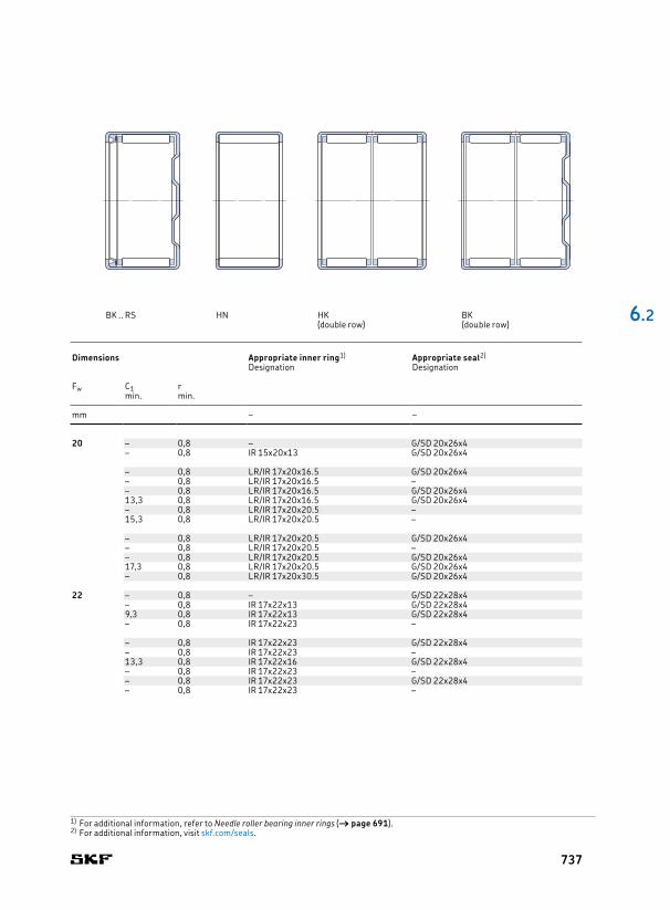
20 26 10 6,16 8,5 0,93 12 000 14 000 12 HK 2010 20 – 0,8 – G/SD 20x26x426 12 8,42 12,5 1,4 12 000 14 000 14 HK 2012 – 0,8 IR 15x20x13 G/SD 20x26x4
26 16 12,3 20,4 2,36 12 000 14 000 19 HK 2016 – 0,8 LR/IR 17x20x16.5 G/SD 20x26x426 16 8,42 12,5 1,4 – 8 000 18 HK 2016.2RS – 0,8 LR/IR 17x20x16.5 –26 16 16,8 36,5 4,25 10 000 12 000 22 HN 2016 – 0,8 LR/IR 17x20x16.5 G/SD 20x26x426 16 12,3 20,4 2,36 12 000 14 000 22 BK 2016 13,3 0,8 LR/IR 17x20x16.5 G/SD 20x26x426 18 12,3 20,4 2,36 – 8 000 21 HK 2018 RS – 0,8 LR/IR 17x20x20.5 –26 18 12,3 20,4 2,36 – 8 000 24 BK 2018 RS 15,3 0,8 LR/IR 17x20x20.5 –
26 20 15,1 26,5 3,15 12 000 14 000 24 HK 2020 – 0,8 LR/IR 17x20x20.5 G/SD 20x26x426 20 12,3 20,4 2,36 – 8 000 23 HK 2020.2RS – 0,8 LR/IR 17x20x20.5 –26 20 20,9 48 5,7 10 000 12 000 29,5 HN 2020 – 0,8 LR/IR 17x20x20.5 G/SD 20x26x426 20 15,1 26,5 3,15 12 000 14 000 27 BK 2020 17,3 0,8 LR/IR 17x20x20.5 G/SD 20x26x426 30 20,9 40,5 4,75 12 000 14 000 35 HK 20301) – 0,8 LR/IR 17x20x30.5 G/SD 20x26x4
22 28 10 7,21 10,6 1,2 11 000 12 000 13 HK 2210 22 – 0,8 – G/SD 22x28x428 12 8,8 13,7 1,56 11 000 12 000 15 HK 2212 – 0,8 IR 17x22x13 G/SD 22x28x428 12 8,8 13,7 1,56 11 000 12 000 18 BK 2212 9,3 0,8 IR 17x22x13 G/SD 22x28x428 14 8,8 13,7 1,56 – 7 500 16 HK 2214 RS – 0,8 IR 17x22x23 –
28 16 13 22,4 2,6 11 000 12 000 21 HK 2216 – 0,8 IR 17x22x23 G/SD 22x28x428 16 8,8 13,7 1,56 – 7 500 18 HK 2216.2RS – 0,8 IR 17x22x23 –28 16 13 22,4 2,6 11 000 12 000 24 BK 2216 13,3 0,8 IR 17x22x16 G/SD 22x28x428 18 13 22,4 2,6 – 7 500 24 HK 2218 RS – 0,8 IR 17x22x23 –28 20 15,7 29 3,45 11 000 12 000 26 HK 2220 – 0,8 IR 17x22x23 G/SD 22x28x428 20 13 22,4 2,6 – 7 500 23 HK 2220.2RS – 0,8 IR 17x22x23 –
6 .2
Principal dimensions Basic load ratings Fatigue
load limitSpeed ratings Mass Designation Dimensions Appropriate inner ring1) Appropriate seal2)
dynamic static Reference speed
Limiting speed
Designation Designation
Fw D C C C0 Pu Fw C1 rmin. min.
mm kN kN r/min g – mm – –
1) For additional information, refer to Needle roller bearing inner rings († page 691).2) For additional information, visit skf.com/seals.
BK .. RS HN HK BK (double row) (double row)
737

25 32 12 10,5 15,3 1,76 9 500 11 000 20 HK 2512 25 – 0,8 LR 20x25x12.5 G 25x32x432 16 15,1 24 2,85 9 500 11 000 27 HK 2516 – 0,8 IR 20x25x17 / LR 20x25x16.5 G 25x32x432 16 10,5 15,3 1,76 – 6 700 27 HK 2516.2RS – 0,8 IR 20x25x17 / LR 20x25x16.5 –32 16 15,1 24 2,85 9 500 11 000 32 BK 2516 13,3 0,8 IR 20x25x17 / LR 20x25x16.5 –32 18 15,1 24 2,85 – 6 700 29 HK 2518 RS – 0,8 LR/IR 20x25x20.5 –32 18 15,1 24 2,85 – 6 700 34 BK 2518 RS 15,3 0,8 LR/IR 20x25x20.5 –
32 20 19 32,5 4 9 500 11 000 33 HK 2520 – 0,8 LR/IR 20x25x20.5 G 25x32x432 20 15,1 24 2,85 – 6 700 31 HK 2520.2RS – 0,8 LR/IR 20x25x20.5 –32 20 26,4 60 7,2 8 000 10 000 39,5 HN 2520 – 0,8 LR/IR 20x25x20.5 G 25x32x432 20 19 32,5 4 9 500 11 000 38 BK 2520 17,3 0,8 LR/IR 20x25x20.5 G 25x32x4
32 24 19 32,5 4 – 6 700 40 HK 2524.2RS – 0,8 – –32 26 24,2 45 5,5 9 500 11 000 44 HK 2526 – 0,8 LR/IR 20x25x26.5 G 25x32x432 26 24,2 45 5,5 9 500 11 000 48 BK 2526 23,3 0,8 LR/IR 20x25x26.5 G 25x32x432 30 24,2 45 5,5 – 6 700 47 HK 2530.2RS – 0,8 IR 20x25x30 –32 38 33 65,5 8 9 500 11 000 64 HK 25381) – 0,8 LR/IR 20x25x38.5 G 25x32x432 38 33 65,5 8 9 500 11 000 68 BK 25381) 35,3 0,8 LR/IR 20x25x38.5 G 25x32x4
28 35 16 15,7 26,5 3,15 9 000 9 500 29 HK 2816 28 – 0,8 IR 22x28x17 G/SD 28x35x435 18 15,7 26,5 3,15 – 6 300 31 HK 2818 RS – 0,8 LR/IR 22x28x20.5 –35 20 20,1 36,5 4,4 9 000 9 500 36 HK 2820 – 0,8 LR/IR 22x28x20.5 G/SD 28x35x435 20 15,7 26,5 3,15 – 6 300 34 HK 2820.2RS – 0,8 LR/IR 22x28x20.5 –35 20 28,1 68 8,15 7 000 9 000 44 HN 2820 – 0,8 LR/IR 22x28x20.5 G/SD 28x35x4
6.2 Drawn cup needle roller bearingsFw 25 – 28 mm
Principal dimensions Basic load ratings Fatigue
load limitSpeed ratings Mass Designation Dimensions Appropriate inner ring1) Appropriate seal2)
dynamic static Reference speed
Limiting speed
Designation Designation
Fw D C C C0 Pu Fw C1 rmin. min.
mm kN kN r/min g – mm – –
1) Double row, outer ring with a lubrication hole
C1
Fw
C
D
r
HK BK HK .. RS HK ...2RS
738
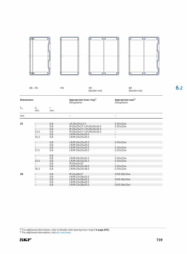
25 32 12 10,5 15,3 1,76 9 500 11 000 20 HK 2512 25 – 0,8 LR 20x25x12.5 G 25x32x432 16 15,1 24 2,85 9 500 11 000 27 HK 2516 – 0,8 IR 20x25x17 / LR 20x25x16.5 G 25x32x432 16 10,5 15,3 1,76 – 6 700 27 HK 2516.2RS – 0,8 IR 20x25x17 / LR 20x25x16.5 –32 16 15,1 24 2,85 9 500 11 000 32 BK 2516 13,3 0,8 IR 20x25x17 / LR 20x25x16.5 –32 18 15,1 24 2,85 – 6 700 29 HK 2518 RS – 0,8 LR/IR 20x25x20.5 –32 18 15,1 24 2,85 – 6 700 34 BK 2518 RS 15,3 0,8 LR/IR 20x25x20.5 –
32 20 19 32,5 4 9 500 11 000 33 HK 2520 – 0,8 LR/IR 20x25x20.5 G 25x32x432 20 15,1 24 2,85 – 6 700 31 HK 2520.2RS – 0,8 LR/IR 20x25x20.5 –32 20 26,4 60 7,2 8 000 10 000 39,5 HN 2520 – 0,8 LR/IR 20x25x20.5 G 25x32x432 20 19 32,5 4 9 500 11 000 38 BK 2520 17,3 0,8 LR/IR 20x25x20.5 G 25x32x4
32 24 19 32,5 4 – 6 700 40 HK 2524.2RS – 0,8 – –32 26 24,2 45 5,5 9 500 11 000 44 HK 2526 – 0,8 LR/IR 20x25x26.5 G 25x32x432 26 24,2 45 5,5 9 500 11 000 48 BK 2526 23,3 0,8 LR/IR 20x25x26.5 G 25x32x432 30 24,2 45 5,5 – 6 700 47 HK 2530.2RS – 0,8 IR 20x25x30 –32 38 33 65,5 8 9 500 11 000 64 HK 25381) – 0,8 LR/IR 20x25x38.5 G 25x32x432 38 33 65,5 8 9 500 11 000 68 BK 25381) 35,3 0,8 LR/IR 20x25x38.5 G 25x32x4
28 35 16 15,7 26,5 3,15 9 000 9 500 29 HK 2816 28 – 0,8 IR 22x28x17 G/SD 28x35x435 18 15,7 26,5 3,15 – 6 300 31 HK 2818 RS – 0,8 LR/IR 22x28x20.5 –35 20 20,1 36,5 4,4 9 000 9 500 36 HK 2820 – 0,8 LR/IR 22x28x20.5 G/SD 28x35x435 20 15,7 26,5 3,15 – 6 300 34 HK 2820.2RS – 0,8 LR/IR 22x28x20.5 –35 20 28,1 68 8,15 7 000 9 000 44 HN 2820 – 0,8 LR/IR 22x28x20.5 G/SD 28x35x4
6 .2
Principal dimensions Basic load ratings Fatigue
load limitSpeed ratings Mass Designation Dimensions Appropriate inner ring1) Appropriate seal2)
dynamic static Reference speed
Limiting speed
Designation Designation
Fw D C C C0 Pu Fw C1 rmin. min.
mm kN kN r/min g – mm – –
1) For additional information, refer to Needle roller bearing inner rings († page 691).2) For additional information, visit skf.com/seals.
BK .. RS HN HK BK (double row) (double row)
739

30 37 12 11,7 18,3 2,12 8 000 9 000 23 HK 3012 30 – 0,8 LR 25x30x12.5 G/SD 30x37x437 12 11,7 18,3 2,12 8 000 9 000 28 BK 3012 9,3 0,8 LR 25x30x12.5 G/SD 30x37x437 16 16,5 29 3,4 8 000 9 000 31 HK 3016 – 0,8 IR 25x30x17 / LR 25x30x16.5 G/SD 30x37x437 16 11,7 18,3 2,12 – 5 600 31 HK 3016.2RS – 0,8 IR 25x30x17 / LR 25x30x16.5 –37 16 16,5 29 3,4 8 000 9 000 38 BK 3016 13,3 0,8 IR 25x30x17 / LR 25x30x16.5 G/SD 30x37x437 18 16,5 29 3,4 – 5 600 37 HK 3018 RS – 0,8 LR/IR 25x30x20.5 –
37 20 20,9 40 4,75 8 000 9 000 39 HK 3020 – 0,8 LR/IR 25x30x20.5 G/SD 30x37x437 20 16,5 29 3,4 – 5 600 36 HK 3020.2RS – 0,8 LR/IR 25x30x20.5 –37 20 20,9 40 4,75 8 000 9 000 47 BK 3020 17,3 0,8 LR/IR 25x30x20.5 G/SD 30x37x437 22 23,8 46,5 5,6 8 000 9 000 42 HK 3022 – 0,8 – G/SD 30x37x4
37 24 20,9 40 4,75 – 5 600 44 HK 3024.2RS – 0,8 – –37 26 27 54 6,55 8 000 9 000 51 HK 3026 – 0,8 LR/IR 25x30x26.5 G/SD 30x37x437 26 27 54 6,55 8 000 9 000 58 BK 3026 23,3 0,8 LR/IR 25x30x26.5 G/SD 30x37x437 38 35,8 80 9,5 8 000 9 000 76 HK 30381) – 0,8 LR/IR 25x30x38.5 G/SD 30x37x437 38 35,8 80 9,5 8 000 9 000 84 BK 30381) 35,3 0,8 LR/IR 25x30x38.5 G/SD 30x37x4
32 39 20 22 43 5,2 7 500 8 500 40,5 HK 3220 32 – 0,8 LR 28x32x20 –39 24 26,4 54 6,55 7 500 8 500 49 HK 3224 – 0,8 – –
35 42 12 12,5 21,6 2,45 7 000 8 000 27 HK 3512 35 – 0,8 LR 30x35x12.5 G/SD 35x42x442 16 17,9 34 4 7 000 8 000 36 HK 3516 – 0,8 IR 30x35x17 / LR 30x35x16.5 G/SD 35x42x442 16 12,5 21,6 2,45 – 5 000 32 HK 3516.2RS – 0,8 IR 30x35x17 / LR 30x35x16.5 –42 18 17,9 34 4 – 5 000 39 HK 3518 RS – 0,8 LR/IR 30x35x20.5 –
42 20 22,9 46,5 5,6 7 000 8 000 44 HK 3520 – 0,8 LR/IR 30x35x20.5 G/SD 35x42x442 20 17,9 34 4 – 5 000 41 HK 3520.2RS – 0,8 LR/IR 30x35x20.5 –42 20 31,4 83 10,2 6 000 7 500 54 HN 3520 – 0,8 LR/IR 30x35x20.5 G/SD 35x42x442 20 22,9 46,5 5,6 7 000 8 000 53 BK 3520 17,3 0,8 LR/IR 30x35x20.5 G/SD 35x42x4
6.2 Drawn cup needle roller bearingsFw 30 – 35 mm
Principal dimensions Basic load ratings Fatigue
load limitSpeed ratings Mass Designation Dimensions Appropriate inner ring1) Appropriate seal2)
dynamic static Reference speed
Limiting speed
Designation Designation
Fw D C C C0 Pu Fw C1 rmin. min.
mm kN kN r/min g – mm – –
1) Double row, outer ring with a lubrication hole
C1
Fw
C
D
r
HK BK HK .. RS HK ...2RS
740

30 37 12 11,7 18,3 2,12 8 000 9 000 23 HK 3012 30 – 0,8 LR 25x30x12.5 G/SD 30x37x437 12 11,7 18,3 2,12 8 000 9 000 28 BK 3012 9,3 0,8 LR 25x30x12.5 G/SD 30x37x437 16 16,5 29 3,4 8 000 9 000 31 HK 3016 – 0,8 IR 25x30x17 / LR 25x30x16.5 G/SD 30x37x437 16 11,7 18,3 2,12 – 5 600 31 HK 3016.2RS – 0,8 IR 25x30x17 / LR 25x30x16.5 –37 16 16,5 29 3,4 8 000 9 000 38 BK 3016 13,3 0,8 IR 25x30x17 / LR 25x30x16.5 G/SD 30x37x437 18 16,5 29 3,4 – 5 600 37 HK 3018 RS – 0,8 LR/IR 25x30x20.5 –
37 20 20,9 40 4,75 8 000 9 000 39 HK 3020 – 0,8 LR/IR 25x30x20.5 G/SD 30x37x437 20 16,5 29 3,4 – 5 600 36 HK 3020.2RS – 0,8 LR/IR 25x30x20.5 –37 20 20,9 40 4,75 8 000 9 000 47 BK 3020 17,3 0,8 LR/IR 25x30x20.5 G/SD 30x37x437 22 23,8 46,5 5,6 8 000 9 000 42 HK 3022 – 0,8 – G/SD 30x37x4
37 24 20,9 40 4,75 – 5 600 44 HK 3024.2RS – 0,8 – –37 26 27 54 6,55 8 000 9 000 51 HK 3026 – 0,8 LR/IR 25x30x26.5 G/SD 30x37x437 26 27 54 6,55 8 000 9 000 58 BK 3026 23,3 0,8 LR/IR 25x30x26.5 G/SD 30x37x437 38 35,8 80 9,5 8 000 9 000 76 HK 30381) – 0,8 LR/IR 25x30x38.5 G/SD 30x37x437 38 35,8 80 9,5 8 000 9 000 84 BK 30381) 35,3 0,8 LR/IR 25x30x38.5 G/SD 30x37x4
32 39 20 22 43 5,2 7 500 8 500 40,5 HK 3220 32 – 0,8 LR 28x32x20 –39 24 26,4 54 6,55 7 500 8 500 49 HK 3224 – 0,8 – –
35 42 12 12,5 21,6 2,45 7 000 8 000 27 HK 3512 35 – 0,8 LR 30x35x12.5 G/SD 35x42x442 16 17,9 34 4 7 000 8 000 36 HK 3516 – 0,8 IR 30x35x17 / LR 30x35x16.5 G/SD 35x42x442 16 12,5 21,6 2,45 – 5 000 32 HK 3516.2RS – 0,8 IR 30x35x17 / LR 30x35x16.5 –42 18 17,9 34 4 – 5 000 39 HK 3518 RS – 0,8 LR/IR 30x35x20.5 –
42 20 22,9 46,5 5,6 7 000 8 000 44 HK 3520 – 0,8 LR/IR 30x35x20.5 G/SD 35x42x442 20 17,9 34 4 – 5 000 41 HK 3520.2RS – 0,8 LR/IR 30x35x20.5 –42 20 31,4 83 10,2 6 000 7 500 54 HN 3520 – 0,8 LR/IR 30x35x20.5 G/SD 35x42x442 20 22,9 46,5 5,6 7 000 8 000 53 BK 3520 17,3 0,8 LR/IR 30x35x20.5 G/SD 35x42x4
6 .2
Principal dimensions Basic load ratings Fatigue
load limitSpeed ratings Mass Designation Dimensions Appropriate inner ring1) Appropriate seal2)
dynamic static Reference speed
Limiting speed
Designation Designation
Fw D C C C0 Pu Fw C1 rmin. min.
mm kN kN r/min g – mm – –
1) For additional information, refer to Needle roller bearing inner rings († page 691).2) For additional information, visit skf.com/seals.
HN HK BK (double row) (double row)
741

40 47 12 13,4 24,5 2,8 6 300 7 000 30 HK 4012 40 – 0,8 LR 35x40x12.5 G/SD 40x47x447 16 19 39 4,55 6 300 7 000 39 HK 4016 – 0,8 IR 35x40x20 / LR 35x40x16.5 G/SD 40x47x447 16 14,5 27,5 3,15 – 4 500 37 HK 4016.2RS – 0,8 IR 35x40x20 / LR 35x40x16.5 –47 18 19 39 4,55 – 4 500 45 HK 4018 RS – 0,8 LR/IR 35x40x20.5 –
47 20 24,2 53 6,4 6 300 7 000 54 HK 4020 – 0,8 LR/IR 35x40x20.5 G/SD 40x47x447 20 19 39 4,55 – 4 500 48 HK 4020.2RS – 0,8 LR/IR 35x40x20.5 –47 20 33,6 95 11,6 5 000 6 300 60,5 HN 4020 – 0,8 LR/IR 35x40x20.5 G/SD 40x47x447 20 24,2 53 6,4 6 300 7 000 62 BK 4020 17,3 0,8 LR/IR 35x40x20.5 G/SD 40x47x4
45 52 12 14,2 27,5 3,2 5 600 6 300 33 HK 4512 45 – 0,8 – G/SD 45x52x452 16 20,5 43 5,1 5 600 6 300 47 HK 4516 – 0,8 IR 40x45x17 / LR 40x45x16.5 G/SD 45x52x452 18 20,5 43 5,1 – 4 000 50 HK 4518 RS – 0,8 LR/IR 40x45x20.5 –
52 20 26 60 7,2 5 600 6 300 56 HK 4520 – 0,8 IR 40x45x20.5 G/SD 45x52x452 20 20,5 43 5,1 – 4 000 54 HK 4520.2RS – 0,8 LR/IR 40x45x20.5 –52 20 35,8 108 13,2 4 500 5 600 66 HN 4520 – 0,8 LR/IR 40x45x20.5 G/SD 45x52x452 20 26 60 7,2 5 600 6 300 72 BK 4520 17,3 0,8 LR/IR 40x45x20.5 G/SD 45x52x452 25 44 140 17 4 500 5 600 85 HN 4525 – 0,8 – G/SD 45x52x4
50 58 20 29,2 63 7,8 5 000 5 600 70 HK 5020 50 – 0,8 LR 45x50x20.5 G/SD 50x58x458 20 41,8 120 14,3 4 000 5 000 85,5 HN 5020 – 0,8 LR 45x50x20.5 G/SD 50x58x458 22 29,2 63 7,8 – 3 600 76 HK 5022 RS – 0,8 LR/IR 45x50x25.5 –58 24 29,2 63 7,8 – 3 600 81 HK 5024.2RS – 0,8 LR/IR 45x50x25.5 –58 25 36,9 85 10,6 5 000 5 600 90 HK 5025 – 0,8 LR/IR 45x50x25.5 G/SD 50x58x458 25 50,1 153 18,6 4 000 5 000 107 HN 5025 – 0,8 LR/IR 45x50x25.5 G/SD 50x58x4
55 63 20 30,3 67 8,3 4 500 5 000 74 HK 5520 55 – 0,8 LR 50x55x20.5 G 55x63x563 28 41,8 104 12,9 4 500 5 000 105 HK 5528 – 0,8 – G 55x63x5
60 68 12 17,6 32 3,8 4 300 4 800 49 HK 6012 60 – 0,8 – –68 20 31,9 75 9,3 4 300 4 800 81 HK 6020 – 0,8 – –68 32 51,2 137 17 4 300 4 800 136 HK 6032 – 0,8 – –
6.2 Drawn cup needle roller bearingsFw 40 – 60 mm
Principal dimensions Basic load ratings Fatigue
load limitSpeed ratings Mass Designation Dimensions Appropriate inner ring1) Appropriate seal2)
dynamic static Reference speed
Limiting speed
Designation Designation
Fw D C C C0 Pu Fw C1 rmin. min.
mm kN kN r/min g – mm – –
C1
Fw
C
D
r
HK BK HK .. RS HK ...2RS
742
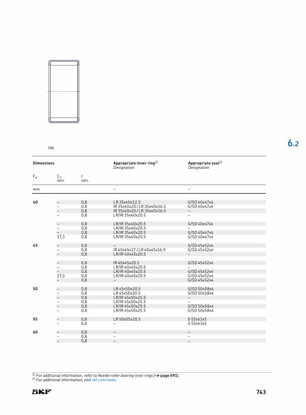
40 47 12 13,4 24,5 2,8 6 300 7 000 30 HK 4012 40 – 0,8 LR 35x40x12.5 G/SD 40x47x447 16 19 39 4,55 6 300 7 000 39 HK 4016 – 0,8 IR 35x40x20 / LR 35x40x16.5 G/SD 40x47x447 16 14,5 27,5 3,15 – 4 500 37 HK 4016.2RS – 0,8 IR 35x40x20 / LR 35x40x16.5 –47 18 19 39 4,55 – 4 500 45 HK 4018 RS – 0,8 LR/IR 35x40x20.5 –
47 20 24,2 53 6,4 6 300 7 000 54 HK 4020 – 0,8 LR/IR 35x40x20.5 G/SD 40x47x447 20 19 39 4,55 – 4 500 48 HK 4020.2RS – 0,8 LR/IR 35x40x20.5 –47 20 33,6 95 11,6 5 000 6 300 60,5 HN 4020 – 0,8 LR/IR 35x40x20.5 G/SD 40x47x447 20 24,2 53 6,4 6 300 7 000 62 BK 4020 17,3 0,8 LR/IR 35x40x20.5 G/SD 40x47x4
45 52 12 14,2 27,5 3,2 5 600 6 300 33 HK 4512 45 – 0,8 – G/SD 45x52x452 16 20,5 43 5,1 5 600 6 300 47 HK 4516 – 0,8 IR 40x45x17 / LR 40x45x16.5 G/SD 45x52x452 18 20,5 43 5,1 – 4 000 50 HK 4518 RS – 0,8 LR/IR 40x45x20.5 –
52 20 26 60 7,2 5 600 6 300 56 HK 4520 – 0,8 IR 40x45x20.5 G/SD 45x52x452 20 20,5 43 5,1 – 4 000 54 HK 4520.2RS – 0,8 LR/IR 40x45x20.5 –52 20 35,8 108 13,2 4 500 5 600 66 HN 4520 – 0,8 LR/IR 40x45x20.5 G/SD 45x52x452 20 26 60 7,2 5 600 6 300 72 BK 4520 17,3 0,8 LR/IR 40x45x20.5 G/SD 45x52x452 25 44 140 17 4 500 5 600 85 HN 4525 – 0,8 – G/SD 45x52x4
50 58 20 29,2 63 7,8 5 000 5 600 70 HK 5020 50 – 0,8 LR 45x50x20.5 G/SD 50x58x458 20 41,8 120 14,3 4 000 5 000 85,5 HN 5020 – 0,8 LR 45x50x20.5 G/SD 50x58x458 22 29,2 63 7,8 – 3 600 76 HK 5022 RS – 0,8 LR/IR 45x50x25.5 –58 24 29,2 63 7,8 – 3 600 81 HK 5024.2RS – 0,8 LR/IR 45x50x25.5 –58 25 36,9 85 10,6 5 000 5 600 90 HK 5025 – 0,8 LR/IR 45x50x25.5 G/SD 50x58x458 25 50,1 153 18,6 4 000 5 000 107 HN 5025 – 0,8 LR/IR 45x50x25.5 G/SD 50x58x4
55 63 20 30,3 67 8,3 4 500 5 000 74 HK 5520 55 – 0,8 LR 50x55x20.5 G 55x63x563 28 41,8 104 12,9 4 500 5 000 105 HK 5528 – 0,8 – G 55x63x5
60 68 12 17,6 32 3,8 4 300 4 800 49 HK 6012 60 – 0,8 – –68 20 31,9 75 9,3 4 300 4 800 81 HK 6020 – 0,8 – –68 32 51,2 137 17 4 300 4 800 136 HK 6032 – 0,8 – –
6 .2
Principal dimensions Basic load ratings Fatigue
load limitSpeed ratings Mass Designation Dimensions Appropriate inner ring1) Appropriate seal2)
dynamic static Reference speed
Limiting speed
Designation Designation
Fw D C C C0 Pu Fw C1 rmin. min.
mm kN kN r/min g – mm – –
1) For additional information, refer to Needle roller bearing inner rings († page 691).2) For additional information, visit skf.com/seals.
HN
743

5 10 10 2,29 2 0,212 36 000 40 000 0,0031 NK 5/10 TN 5 0,15 8,8 0,1 G 5x10x2 S10 12 2,92 2,7 0,29 36 000 40 000 0,0037 NK 5/12 TN 0,15 8,8 0,1 G 5x10x2 S
6 12 10 2,55 2,36 0,25 34 000 38 000 0,0047 NK 6/10 TN 6 0,15 10,8 0,1 G 6x12x2 S12 12 3,3 3,2 0,345 34 000 38 000 0,0057 NK 6/12 TN 0,15 10,8 0,1 G 6x12x2 S
7 14 10 2,81 2,75 0,29 32 000 36 000 0,0069 NK 7/10 TN 7 0,3 12 0,3 G 7x14x214 12 3,58 3,75 0,415 32 000 36 000 0,0082 NK 7/12 TN 0,3 12 0,3 G 7x14x2
8 15 12 3,8 4,25 0,465 32 000 36 000 0,0087 NK 8/12 TN 8 0,3 13 0,3 G/SD 8x15x315 16 5,01 5,85 0,67 32 000 36 000 0,012 NK 8/16 TN 0,3 13 0,3 G/SD 8x15x3
9 16 12 4,4 5,2 0,57 30 000 34 000 0,01 NK 9/12 TN 9 0,3 14 0,3 G 9x16x316 16 5,72 7,2 0,815 30 000 34 000 0,013 NK 9/16 TN 0,3 14 0,3 G 9x16x3
10 17 12 4,57 5,7 0,63 28 000 32 000 0,01 NK 10/12 TN 10 0,3 15 0,3 G/SD 10x17x317 16 5,94 8 0,9 28 000 32 000 0,013 NK 10/16 TN 0,3 15 0,3 G/SD 10x17x3
12 19 12 6,71 8,15 0,965 26 000 30 000 0,012 NK 12/12 12 0,3 17 0,3 G/SD 12x19x319 16 9,13 12 1,43 26 000 30 000 0,016 NK 12/16 0,3 17 0,3 G/SD 12x19x3
14 22 13 8,8 10,4 1,22 24 000 28 000 0,017 RNA 4900 14 0,3 20 0,3 G/SD 14x22x322 13 7,37 8,15 0,965 – 12 000 0,016 RNA 4900 RS 0,3 20 0,3 –22 13 7,37 8,15 0,965 – 12 000 0,016 RNA 4900.2RS 0,3 20 0,3 –22 16 10,2 12,5 1,5 24 000 28 000 0,021 NK 14/16 0,3 20 0,3 G/SD 14x22x322 20 12,8 16,6 2 24 000 28 000 0,026 NK 14/20 0,3 20 0,3 G/SD 14x22x3
15 23 16 11 14 1,66 24 000 26 000 0,022 NK 15/16 15 0,3 21 0,3 G/SD 15x23x323 20 13,8 18,3 2,2 24 000 26 000 0,027 NK 15/20 0,3 21 0,3 G/SD 15x23x3
16 24 13 9,9 12,2 1,46 22 000 26 000 0,017 RNA 4901 16 0,3 22 0,3 G/SD 16x24x324 13 8,09 9,65 1,14 – 11 000 0,018 RNA 4901 RS 0,3 22 0,3 –24 13 8,09 9,65 1,14 – 11 000 0,018 RNA 4901.2RS 0,3 22 0,3 –24 16 11,7 15,3 1,8 22 000 26 000 0,022 NK 16/16 0,3 22 0,3 G/SD 16x24x324 20 14,5 20 2,4 22 000 26 000 0,028 NK 16/20 0,3 22 0,3 G/SD 16x24x324 22 16,1 23,2 2,75 22 000 26 000 0,031 RNA 6901 0,3 22 0,3 G/SD 16x24x3
17 25 16 12,1 16,6 1,96 22 000 26 000 0,024 NK 17/16 17 0,3 23 0,3 G/SD 17x25x325 20 15,1 22 2,65 22 000 26 000 0,03 NK 17/20 0,3 23 0,3 G/SD 17x25x3
C
Fw
r1
r2
D
NK (Fw ≤ 10 mm) NK (Fw ≥ 12 mm) RNA 49 .. RS RNA 49 ...2RS RNA 49 RNA 6901
6.3 Needle roller bearings with machined rings with flanges, without an inner ringFw 5 – 17 mm
Principal dimensions Basic load ratings Fatigue
load limitSpeed ratings Mass Designation Dimensions Abutment and fillet
dimensionsAppropriate seal1)
dynamic static Reference speed
Limiting speed
Designation
Fw D C C C0 Pu Fw r1,2 Da ramin. max. max.
mm kN kN r/min kg – mm mm –
744
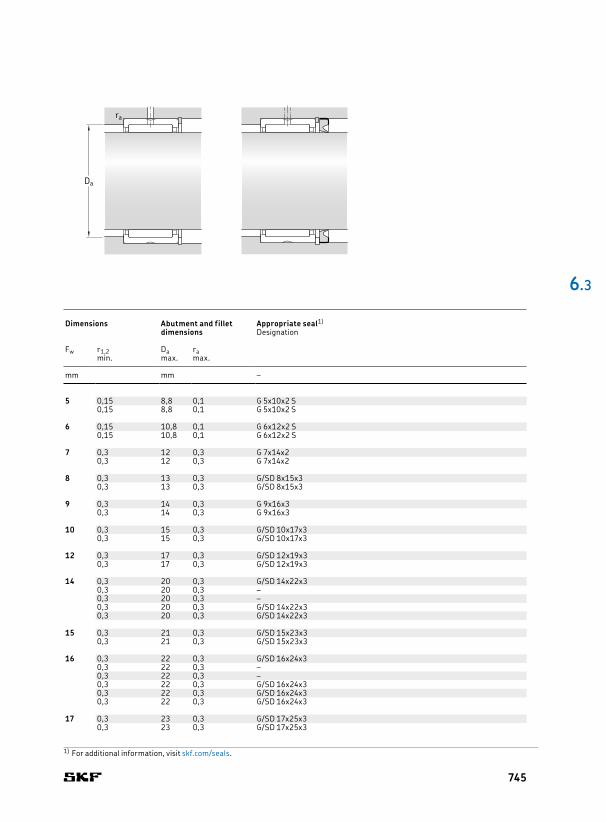
5 10 10 2,29 2 0,212 36 000 40 000 0,0031 NK 5/10 TN 5 0,15 8,8 0,1 G 5x10x2 S10 12 2,92 2,7 0,29 36 000 40 000 0,0037 NK 5/12 TN 0,15 8,8 0,1 G 5x10x2 S
6 12 10 2,55 2,36 0,25 34 000 38 000 0,0047 NK 6/10 TN 6 0,15 10,8 0,1 G 6x12x2 S12 12 3,3 3,2 0,345 34 000 38 000 0,0057 NK 6/12 TN 0,15 10,8 0,1 G 6x12x2 S
7 14 10 2,81 2,75 0,29 32 000 36 000 0,0069 NK 7/10 TN 7 0,3 12 0,3 G 7x14x214 12 3,58 3,75 0,415 32 000 36 000 0,0082 NK 7/12 TN 0,3 12 0,3 G 7x14x2
8 15 12 3,8 4,25 0,465 32 000 36 000 0,0087 NK 8/12 TN 8 0,3 13 0,3 G/SD 8x15x315 16 5,01 5,85 0,67 32 000 36 000 0,012 NK 8/16 TN 0,3 13 0,3 G/SD 8x15x3
9 16 12 4,4 5,2 0,57 30 000 34 000 0,01 NK 9/12 TN 9 0,3 14 0,3 G 9x16x316 16 5,72 7,2 0,815 30 000 34 000 0,013 NK 9/16 TN 0,3 14 0,3 G 9x16x3
10 17 12 4,57 5,7 0,63 28 000 32 000 0,01 NK 10/12 TN 10 0,3 15 0,3 G/SD 10x17x317 16 5,94 8 0,9 28 000 32 000 0,013 NK 10/16 TN 0,3 15 0,3 G/SD 10x17x3
12 19 12 6,71 8,15 0,965 26 000 30 000 0,012 NK 12/12 12 0,3 17 0,3 G/SD 12x19x319 16 9,13 12 1,43 26 000 30 000 0,016 NK 12/16 0,3 17 0,3 G/SD 12x19x3
14 22 13 8,8 10,4 1,22 24 000 28 000 0,017 RNA 4900 14 0,3 20 0,3 G/SD 14x22x322 13 7,37 8,15 0,965 – 12 000 0,016 RNA 4900 RS 0,3 20 0,3 –22 13 7,37 8,15 0,965 – 12 000 0,016 RNA 4900.2RS 0,3 20 0,3 –22 16 10,2 12,5 1,5 24 000 28 000 0,021 NK 14/16 0,3 20 0,3 G/SD 14x22x322 20 12,8 16,6 2 24 000 28 000 0,026 NK 14/20 0,3 20 0,3 G/SD 14x22x3
15 23 16 11 14 1,66 24 000 26 000 0,022 NK 15/16 15 0,3 21 0,3 G/SD 15x23x323 20 13,8 18,3 2,2 24 000 26 000 0,027 NK 15/20 0,3 21 0,3 G/SD 15x23x3
16 24 13 9,9 12,2 1,46 22 000 26 000 0,017 RNA 4901 16 0,3 22 0,3 G/SD 16x24x324 13 8,09 9,65 1,14 – 11 000 0,018 RNA 4901 RS 0,3 22 0,3 –24 13 8,09 9,65 1,14 – 11 000 0,018 RNA 4901.2RS 0,3 22 0,3 –24 16 11,7 15,3 1,8 22 000 26 000 0,022 NK 16/16 0,3 22 0,3 G/SD 16x24x324 20 14,5 20 2,4 22 000 26 000 0,028 NK 16/20 0,3 22 0,3 G/SD 16x24x324 22 16,1 23,2 2,75 22 000 26 000 0,031 RNA 6901 0,3 22 0,3 G/SD 16x24x3
17 25 16 12,1 16,6 1,96 22 000 26 000 0,024 NK 17/16 17 0,3 23 0,3 G/SD 17x25x325 20 15,1 22 2,65 22 000 26 000 0,03 NK 17/20 0,3 23 0,3 G/SD 17x25x3
6 .3
Da
ra
Principal dimensions Basic load ratings Fatigue
load limitSpeed ratings Mass Designation Dimensions Abutment and fillet
dimensionsAppropriate seal1)
dynamic static Reference speed
Limiting speed
Designation
Fw D C C C0 Pu Fw r1,2 Da ramin. max. max.
mm kN kN r/min kg – mm mm –
1) For additional information, visit skf.com/seals.
745

18 26 16 12,8 17,6 2,12 22 000 24 000 0,025 NK 18/16 18 0,3 24 0,3 G/SD 18x26x426 20 16,1 23,6 2,85 22 000 24 000 0,031 NK 18/20 0,3 24 0,3 G/SD 18x26x4
19 27 16 13,4 19 2,28 20 000 24 000 0,026 NK 19/16 19 0,3 25 0,3 G/SD 19x27x427 20 16,5 25,5 3,05 20 000 24 000 0,032 NK 19/20 0,3 25 0,3 G/SD 19x27x4
20 28 13 11,2 15,3 1,83 19 000 22 000 0,022 RNA 4902 20 0,3 26 0,3 G/SD 20x28x428 13 9,13 12 1,43 – 9 500 0,02 RNA 4902 RS 0,3 26 0,3 –28 13 9,13 12 1,43 – 9 500 0,022 RNA 4902.2RS 0,3 26 0,3 –28 16 13,2 19,3 2,28 19 000 22 000 0,027 NK 20/16 0,3 26 0,3 G/SD 20x28x4
28 20 16,5 25,5 3,05 19 000 22 000 0,034 NK 20/20 0,3 26 0,3 G/SD 20x28x428 23 17,2 27 3,35 19 000 22 000 0,04 RNA 6902 0,3 26 0,3 G/SD 20x28x432 20 23,3 27 3,25 18 000 20 000 0,049 NKS 20 0,6 28 0,6 CR 20x32x7 HMS5 RG
21 29 16 13,8 20,4 2,45 19 000 22 000 0,028 NK 21/16 21 0,3 27 0,3 G 21x29x429 20 17,2 27 3,35 19 000 22 000 0,035 NK 21/20 0,3 27 0,3 G 21x29x4
22 30 13 11,4 16,3 1,96 18 000 20 000 0,022 RNA 4903 22 0,3 28 0,3 G/SD 22x30x430 13 9,52 12,9 1,53 – 9 000 0,023 RNA 4903 RS 0,3 28 0,3 –30 13 9,52 12,9 1,53 – 9 000 0,023 RNA 4903.2RS 0,3 28 0,3 –30 16 14,2 21,6 2,6 18 000 20 000 0,03 NK 22/16 0,3 28 0,3 G/SD 22x30x4
30 20 17,9 29 3,55 18 000 20 000 0,037 NK 22/20 0,3 28 0,3 G/SD 22x30x430 23 18,7 30,5 3,75 18 000 20 000 0,042 RNA 6903 0,3 28 0,3 G/SD 22x30x435 20 24,6 30 3,65 16 000 19 000 0,062 NKS 22 0,6 31 0,6 CR 22x35x7 HMS5 RG
24 32 16 15,4 24,5 2,9 16 000 19 000 0,032 NK 24/16 24 0,3 30 0,3 G/SD 24x32x432 20 19 32,5 4 16 000 19 000 0,04 NK 24/20 0,3 30 0,3 G/SD 24x32x437 20 26 33,5 4 15 000 17 000 0,066 NKS 24 0,6 33 0,6 CR 24x37x7 HMS5 RG
25 33 16 15,1 24,5 2,9 16 000 18 000 0,033 NK 25/16 25 0,3 31 0,3 G/SD 25x33x433 20 19 32,5 4 16 000 18 000 0,042 NK 25/20 0,3 31 0,3 G/SD 25x33x437 17 21,6 28 3,35 15 000 17 000 0,052 RNA 4904 0,3 35 0,3 CR 25x37x5 HMS5 RG37 17 19,4 22,4 2,65 – 7 500 0,056 RNA 4904 RS 0,3 35 0,3 –37 17 19,4 22,4 2,65 – 7 500 0,056 RNA 4904.2RS 0,3 35 0,3 –
37 30 35,2 53 6,55 15 000 17 000 0,1 RNA 6904 0,3 35 0,3 CR 25x37x5 HMS5 RG38 20 27,5 36 4,4 15 000 17 000 0,068 NKS 25 0,6 34 0,6 CR 25x38x7 HMS5 RG
6.3 Needle roller bearings with machined rings with flanges, without an inner ringFw 18 – 25 mm
Principal dimensions Basic load ratings Fatigue
load limitSpeed ratings Mass Designation Dimensions Abutment and fillet
dimensionsAppropriate seal1)
dynamic static Reference speed
Limiting speed
Designation
Fw D C C C0 Pu Fw r1,2 Da ramin. max. max.
mm kN kN r/min kg – mm mm –
Fw
C
D
r2r1
NK(S) RNA 49 .. RS RNA 49 ...2RS RNA 49RNA 69
746
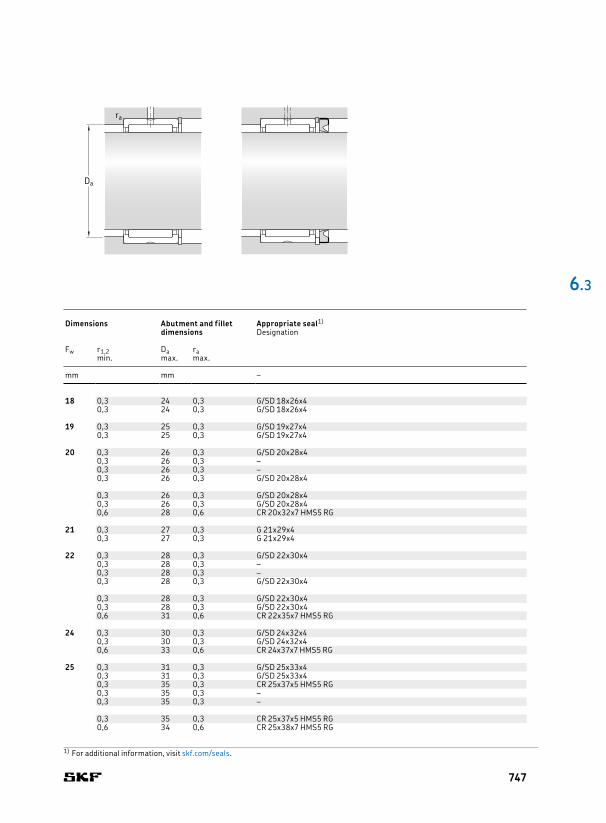
18 26 16 12,8 17,6 2,12 22 000 24 000 0,025 NK 18/16 18 0,3 24 0,3 G/SD 18x26x426 20 16,1 23,6 2,85 22 000 24 000 0,031 NK 18/20 0,3 24 0,3 G/SD 18x26x4
19 27 16 13,4 19 2,28 20 000 24 000 0,026 NK 19/16 19 0,3 25 0,3 G/SD 19x27x427 20 16,5 25,5 3,05 20 000 24 000 0,032 NK 19/20 0,3 25 0,3 G/SD 19x27x4
20 28 13 11,2 15,3 1,83 19 000 22 000 0,022 RNA 4902 20 0,3 26 0,3 G/SD 20x28x428 13 9,13 12 1,43 – 9 500 0,02 RNA 4902 RS 0,3 26 0,3 –28 13 9,13 12 1,43 – 9 500 0,022 RNA 4902.2RS 0,3 26 0,3 –28 16 13,2 19,3 2,28 19 000 22 000 0,027 NK 20/16 0,3 26 0,3 G/SD 20x28x4
28 20 16,5 25,5 3,05 19 000 22 000 0,034 NK 20/20 0,3 26 0,3 G/SD 20x28x428 23 17,2 27 3,35 19 000 22 000 0,04 RNA 6902 0,3 26 0,3 G/SD 20x28x432 20 23,3 27 3,25 18 000 20 000 0,049 NKS 20 0,6 28 0,6 CR 20x32x7 HMS5 RG
21 29 16 13,8 20,4 2,45 19 000 22 000 0,028 NK 21/16 21 0,3 27 0,3 G 21x29x429 20 17,2 27 3,35 19 000 22 000 0,035 NK 21/20 0,3 27 0,3 G 21x29x4
22 30 13 11,4 16,3 1,96 18 000 20 000 0,022 RNA 4903 22 0,3 28 0,3 G/SD 22x30x430 13 9,52 12,9 1,53 – 9 000 0,023 RNA 4903 RS 0,3 28 0,3 –30 13 9,52 12,9 1,53 – 9 000 0,023 RNA 4903.2RS 0,3 28 0,3 –30 16 14,2 21,6 2,6 18 000 20 000 0,03 NK 22/16 0,3 28 0,3 G/SD 22x30x4
30 20 17,9 29 3,55 18 000 20 000 0,037 NK 22/20 0,3 28 0,3 G/SD 22x30x430 23 18,7 30,5 3,75 18 000 20 000 0,042 RNA 6903 0,3 28 0,3 G/SD 22x30x435 20 24,6 30 3,65 16 000 19 000 0,062 NKS 22 0,6 31 0,6 CR 22x35x7 HMS5 RG
24 32 16 15,4 24,5 2,9 16 000 19 000 0,032 NK 24/16 24 0,3 30 0,3 G/SD 24x32x432 20 19 32,5 4 16 000 19 000 0,04 NK 24/20 0,3 30 0,3 G/SD 24x32x437 20 26 33,5 4 15 000 17 000 0,066 NKS 24 0,6 33 0,6 CR 24x37x7 HMS5 RG
25 33 16 15,1 24,5 2,9 16 000 18 000 0,033 NK 25/16 25 0,3 31 0,3 G/SD 25x33x433 20 19 32,5 4 16 000 18 000 0,042 NK 25/20 0,3 31 0,3 G/SD 25x33x437 17 21,6 28 3,35 15 000 17 000 0,052 RNA 4904 0,3 35 0,3 CR 25x37x5 HMS5 RG37 17 19,4 22,4 2,65 – 7 500 0,056 RNA 4904 RS 0,3 35 0,3 –37 17 19,4 22,4 2,65 – 7 500 0,056 RNA 4904.2RS 0,3 35 0,3 –
37 30 35,2 53 6,55 15 000 17 000 0,1 RNA 6904 0,3 35 0,3 CR 25x37x5 HMS5 RG38 20 27,5 36 4,4 15 000 17 000 0,068 NKS 25 0,6 34 0,6 CR 25x38x7 HMS5 RG
6 .3
Principal dimensions Basic load ratings Fatigue
load limitSpeed ratings Mass Designation Dimensions Abutment and fillet
dimensionsAppropriate seal1)
dynamic static Reference speed
Limiting speed
Designation
Fw D C C C0 Pu Fw r1,2 Da ramin. max. max.
mm kN kN r/min kg – mm mm –
1) For additional information, visit skf.com/seals.
Da
ra
747

26 34 16 15,7 26 3,1 15 000 17 000 0,034 NK 26/16 26 0,3 32 0,3 G/SD 26x34x434 20 19,4 34,5 4,25 15 000 17 000 0,042 NK 26/20 0,3 32 0,3 G/SD 26x34x4
28 37 20 22 36,5 4,55 14 000 16 000 0,052 NK 28/20 28 0,3 35 0,3 G 28x37x437 30 31,9 60 7,5 14 000 16 000 0,082 NK 28/30 0,3 35 0,3 G 28x37x439 17 23,3 32 3,9 14 000 15 000 0,05 RNA 49/22 0,3 37 0,3 –39 30 36,9 57 7,2 14 000 15 000 0,098 RNA 69/22 0,3 37 0,3 –42 20 28,6 39 4,75 13 000 15 000 0,084 NKS 28 0,6 38 0,6 CR 28x42x7 HMS5 RG
29 38 20 24,6 42,5 5,2 14 000 15 000 0,05 NK 29/20 TN 29 0,3 36 0,3 G 29x38x438 30 31,9 60 7,5 14 000 15 000 0,084 NK 29/30 0,3 36 0,3 G 29x38x4
30 40 20 25,1 44 5,5 13 000 15 000 0,061 NK 30/20 TN 30 0,3 38 0,3 G/SD 30x40x440 30 36,9 72 9 13 000 15 000 0,092 NK 30/30 TN 0,3 38 0,3 G/SD 30x40x442 17 24,2 34,5 4,15 13 000 15 000 0,061 RNA 4905 0,3 40 0,3 CR 30x42x6 HMS5 RG42 17 21,6 27,5 3,25 – 6 300 0,06 RNA 4905 RS 0,3 40 0,3 –42 17 21,6 27,5 3,25 – 6 300 0,06 RNA 4905.2RS 0,3 40 0,3 –
42 30 38 62 7,65 13 000 15 000 0,11 RNA 6905 0,3 40 0,3 CR 30x42x6 HMS5 RG45 22 31,9 43 5,3 12 000 14 000 0,1 NKS 30 0,6 41 0,6 CR 30x45x7 HMS5 RG
32 42 20 26,4 48 6 12 000 14 000 0,064 NK 32/20 TN 32 0,3 40 0,3 G/SD 32x42x442 30 34,1 65,5 8,3 12 000 14 000 0,1 NK 32/30 0,3 40 0,3 G/SD 32x42x445 17 25,1 36,5 4,4 12 000 14 000 0,073 RNA 49/28 0,3 43 0,3 G 32x45x445 30 39,6 65,5 8,3 12 000 14 000 0,14 RNA 69/28 0,3 43 0,3 G 32x45x447 22 34,1 46,5 5,7 12 000 13 000 0,11 NKS 32 0,6 43 0,6 CR 32x47x6 HMS5 RG
35 45 20 27,5 52 6,55 11 000 13 000 0,069 NK 35/20 TN 35 0,3 43 0,3 G/SD 35x45x445 30 40,2 85 10,6 11 000 13 000 0,11 NK 35/30 TN 0,3 43 0,3 G/SD 35x45x447 17 25,5 39 4,65 11 000 13 000 0,069 RNA 4906 0,3 45 0,3 CR 35x47x6 HMS5 RG47 17 23,3 32 3,8 – 5 600 0,069 RNA 4906 RS 0,3 45 0,3 –47 17 23,3 32 3,8 – 5 600 0,069 RNA 4906.2RS 0,3 45 0,3 –
47 30 42,9 75 9,3 11 000 13 000 0,13 RNA 6906 0,3 45 0,3 CR 35x47x6 HMS5 RG50 22 35,2 50 6,2 11 000 12 000 0,12 NKS 35 0,6 46 0,6 CR 35x50x7 HMS5 RG
37 47 20 25,1 46,5 5,85 11 000 12 000 0,077 NK 37/20 37 0,3 45 0,3 G/SD 37x47x447 30 36,9 76,5 9,5 11 000 12 000 0,11 NK 37/30 0,3 45 0,3 G/SD 37x47x452 22 36,9 54 6,55 10 000 12 000 0,12 NKS 37 0,6 48 0,6 CR 37x52x8 HMS4 R
6.3 Needle roller bearings with machined rings with flanges, without an inner ringFw 26 – 37 mm
Principal dimensions Basic load ratings Fatigue
load limitSpeed ratings Mass Designation Dimensions Abutment and fillet
dimensionsAppropriate seal1)
dynamic static Reference speed
Limiting speed
Designation
Fw D C C C0 Pu Fw r1,2 Da ramin. max. max.
mm kN kN r/min kg – mm mm –
Fw
C
D
r2r1
NK(S) RNA 49 .. RS RNA 49 ...2RS RNA 49RNA 69
748

26 34 16 15,7 26 3,1 15 000 17 000 0,034 NK 26/16 26 0,3 32 0,3 G/SD 26x34x434 20 19,4 34,5 4,25 15 000 17 000 0,042 NK 26/20 0,3 32 0,3 G/SD 26x34x4
28 37 20 22 36,5 4,55 14 000 16 000 0,052 NK 28/20 28 0,3 35 0,3 G 28x37x437 30 31,9 60 7,5 14 000 16 000 0,082 NK 28/30 0,3 35 0,3 G 28x37x439 17 23,3 32 3,9 14 000 15 000 0,05 RNA 49/22 0,3 37 0,3 –39 30 36,9 57 7,2 14 000 15 000 0,098 RNA 69/22 0,3 37 0,3 –42 20 28,6 39 4,75 13 000 15 000 0,084 NKS 28 0,6 38 0,6 CR 28x42x7 HMS5 RG
29 38 20 24,6 42,5 5,2 14 000 15 000 0,05 NK 29/20 TN 29 0,3 36 0,3 G 29x38x438 30 31,9 60 7,5 14 000 15 000 0,084 NK 29/30 0,3 36 0,3 G 29x38x4
30 40 20 25,1 44 5,5 13 000 15 000 0,061 NK 30/20 TN 30 0,3 38 0,3 G/SD 30x40x440 30 36,9 72 9 13 000 15 000 0,092 NK 30/30 TN 0,3 38 0,3 G/SD 30x40x442 17 24,2 34,5 4,15 13 000 15 000 0,061 RNA 4905 0,3 40 0,3 CR 30x42x6 HMS5 RG42 17 21,6 27,5 3,25 – 6 300 0,06 RNA 4905 RS 0,3 40 0,3 –42 17 21,6 27,5 3,25 – 6 300 0,06 RNA 4905.2RS 0,3 40 0,3 –
42 30 38 62 7,65 13 000 15 000 0,11 RNA 6905 0,3 40 0,3 CR 30x42x6 HMS5 RG45 22 31,9 43 5,3 12 000 14 000 0,1 NKS 30 0,6 41 0,6 CR 30x45x7 HMS5 RG
32 42 20 26,4 48 6 12 000 14 000 0,064 NK 32/20 TN 32 0,3 40 0,3 G/SD 32x42x442 30 34,1 65,5 8,3 12 000 14 000 0,1 NK 32/30 0,3 40 0,3 G/SD 32x42x445 17 25,1 36,5 4,4 12 000 14 000 0,073 RNA 49/28 0,3 43 0,3 G 32x45x445 30 39,6 65,5 8,3 12 000 14 000 0,14 RNA 69/28 0,3 43 0,3 G 32x45x447 22 34,1 46,5 5,7 12 000 13 000 0,11 NKS 32 0,6 43 0,6 CR 32x47x6 HMS5 RG
35 45 20 27,5 52 6,55 11 000 13 000 0,069 NK 35/20 TN 35 0,3 43 0,3 G/SD 35x45x445 30 40,2 85 10,6 11 000 13 000 0,11 NK 35/30 TN 0,3 43 0,3 G/SD 35x45x447 17 25,5 39 4,65 11 000 13 000 0,069 RNA 4906 0,3 45 0,3 CR 35x47x6 HMS5 RG47 17 23,3 32 3,8 – 5 600 0,069 RNA 4906 RS 0,3 45 0,3 –47 17 23,3 32 3,8 – 5 600 0,069 RNA 4906.2RS 0,3 45 0,3 –
47 30 42,9 75 9,3 11 000 13 000 0,13 RNA 6906 0,3 45 0,3 CR 35x47x6 HMS5 RG50 22 35,2 50 6,2 11 000 12 000 0,12 NKS 35 0,6 46 0,6 CR 35x50x7 HMS5 RG
37 47 20 25,1 46,5 5,85 11 000 12 000 0,077 NK 37/20 37 0,3 45 0,3 G/SD 37x47x447 30 36,9 76,5 9,5 11 000 12 000 0,11 NK 37/30 0,3 45 0,3 G/SD 37x47x452 22 36,9 54 6,55 10 000 12 000 0,12 NKS 37 0,6 48 0,6 CR 37x52x8 HMS4 R
6 .3
Principal dimensions Basic load ratings Fatigue
load limitSpeed ratings Mass Designation Dimensions Abutment and fillet
dimensionsAppropriate seal1)
dynamic static Reference speed
Limiting speed
Designation
Fw D C C C0 Pu Fw r1,2 Da ramin. max. max.
mm kN kN r/min kg – mm mm –
1) For additional information, visit skf.com/seals.
Da
ra
749

38 48 20 25,5 49 6,1 11 000 12 000 0,079 NK 38/20 38 0,3 46 0,3 G/SD 38x48x448 30 37,4 80 10 11 000 12 000 0,12 NK 38/30 0,3 46 0,3 G/SD 38x48x4
40 50 20 29,7 60 7,5 10 000 11 000 0,078 NK 40/20 TN 40 0,3 48 0,3 G/SD 40x50x450 30 38 83 10,4 10 000 11 000 0,13 NK 40/30 0,3 48 0,3 G/SD 40x50x452 20 30,8 51 6,3 10 000 11 000 0,089 RNA 49/32 0,6 48 0,6 G/SD 40x52x552 36 47,3 90 10,8 10 000 11 000 0,16 RNA 69/32 0,6 48 0,6 G/SD 40x52x555 22 38 57 7,1 9 500 11 000 0,13 NKS 40 0,6 51 0,6 CR 40x55x7 HMS5 RG
42 52 20 27 53 6,55 9 500 11 000 0,086 NK 42/20 42 0,3 50 0,3 G/SD 42x52x452 30 39,1 86,5 10,8 9 500 11 000 0,13 NK 42/30 0,3 50 0,3 G/SD 42x52x455 20 31,9 54 6,7 9 500 11 000 0,11 RNA 4907 0,6 51 0,6 CR 42x55x7 HMS5 RG55 20 27 43 5,3 – 4 800 0,11 RNA 4907 RS 0,6 51 0,6 –55 20 27 43 5,3 – 4 800 0,11 RNA 4907.2RS 0,6 51 0,6 –55 36 48,4 93 11,4 9 500 11 000 0,19 RNA 6907 0,6 51 0,6 CR 42x55x7 HMS5 RG
43 53 20 27,5 55 6,8 9 500 11 000 0,086 NK 43/20 43 0,3 51 0,3 G 43x53x453 30 40,2 90 11,2 9 500 11 000 0,13 NK 43/30 0,3 51 0,3 G 43x53x458 22 39,1 61 7,5 9 000 10 000 0,14 NKS 43 0,6 53 0,6 –
45 55 20 31,4 65,5 8,3 9 000 10 000 0,085 NK 45/20 TN 45 0,3 53 0,3 G/SD 45x55x455 30 45,7 108 13,7 9 000 10 000 0,13 NK 45/30 TN 0,3 53 0,3 G/SD 45x55x460 22 40,2 64 8 8 500 10 000 0,15 NKS 45 0,6 56 0,6 CR 45x60x7 HMS5 RG
47 57 20 29,2 61 7,65 8 500 10 000 0,095 NK 47/20 47 0,3 55 0,3 –57 30 41,8 98 12,5 8 500 10 000 0,14 NK 47/30 0,3 55 0,3 –
48 62 22 42,9 71 8,8 8 000 9 500 0,14 RNA 4908 48 0,6 58 0,6 CR 48x62x8 HMS5 RG62 22 36,9 58,5 7,1 – 4 000 0,15 RNA 4908 RS 0,6 58 0,6 –62 22 36,9 58,5 7,1 – 4 000 0,15 RNA 4908.2RS 0,6 58 0,6 –62 40 67,1 125 15,3 8 000 9 500 0,26 RNA 6908 0,6 58 0,6 CR 48x62x8 HMS5 RG
50 62 25 42,9 91,5 11,2 8 000 9 000 0,15 NK 50/25 TN 50 0,6 58 0,6 G/SD 50x62x562 35 58,3 137 17 8 000 9 000 0,21 NK 50/35 TN 0,6 58 0,6 G/SD 50x62x565 22 42,9 72 8,8 8 000 9 000 0,16 NKS 50 1 60 1 CR 50x65x8 HMS5 RG
52 68 22 45,7 78 9,65 7 500 8 500 0,18 RNA 4909 52 0,6 64 0,6 CR 52X68X8 HMS5 RG68 22 39,1 64 7,8 – 3 800 0,16 RNA 4909 RS 0,6 64 0,6 –68 22 39,1 64 7,8 – 3 800 0,16 RNA 4909.2RS 0,6 64 0,6 –68 40 70,4 137 17 7 500 8 500 0,34 RNA 6909 0,6 64 0,6 CR 52x68x8 HMS5 RG
6.3 Needle roller bearings with machined rings with flanges, without an inner ringFw 38 – 52 mm
Principal dimensions Basic load ratings Fatigue
load limitSpeed ratings Mass Designation Dimensions Abutment and fillet
dimensionsAppropriate seal1)
dynamic static Reference speed
Limiting speed
Designation
Fw D C C C0 Pu Fw r1,2 Da ramin. max. max.
mm kN kN r/min kg – mm mm –
Fw
C
D
r2r1
Fw
C
D
r2r1
NK(S) RNA 49 .. RS RNA 49 ...2RS RNA 69RNA 49
750
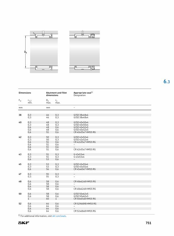
38 48 20 25,5 49 6,1 11 000 12 000 0,079 NK 38/20 38 0,3 46 0,3 G/SD 38x48x448 30 37,4 80 10 11 000 12 000 0,12 NK 38/30 0,3 46 0,3 G/SD 38x48x4
40 50 20 29,7 60 7,5 10 000 11 000 0,078 NK 40/20 TN 40 0,3 48 0,3 G/SD 40x50x450 30 38 83 10,4 10 000 11 000 0,13 NK 40/30 0,3 48 0,3 G/SD 40x50x452 20 30,8 51 6,3 10 000 11 000 0,089 RNA 49/32 0,6 48 0,6 G/SD 40x52x552 36 47,3 90 10,8 10 000 11 000 0,16 RNA 69/32 0,6 48 0,6 G/SD 40x52x555 22 38 57 7,1 9 500 11 000 0,13 NKS 40 0,6 51 0,6 CR 40x55x7 HMS5 RG
42 52 20 27 53 6,55 9 500 11 000 0,086 NK 42/20 42 0,3 50 0,3 G/SD 42x52x452 30 39,1 86,5 10,8 9 500 11 000 0,13 NK 42/30 0,3 50 0,3 G/SD 42x52x455 20 31,9 54 6,7 9 500 11 000 0,11 RNA 4907 0,6 51 0,6 CR 42x55x7 HMS5 RG55 20 27 43 5,3 – 4 800 0,11 RNA 4907 RS 0,6 51 0,6 –55 20 27 43 5,3 – 4 800 0,11 RNA 4907.2RS 0,6 51 0,6 –55 36 48,4 93 11,4 9 500 11 000 0,19 RNA 6907 0,6 51 0,6 CR 42x55x7 HMS5 RG
43 53 20 27,5 55 6,8 9 500 11 000 0,086 NK 43/20 43 0,3 51 0,3 G 43x53x453 30 40,2 90 11,2 9 500 11 000 0,13 NK 43/30 0,3 51 0,3 G 43x53x458 22 39,1 61 7,5 9 000 10 000 0,14 NKS 43 0,6 53 0,6 –
45 55 20 31,4 65,5 8,3 9 000 10 000 0,085 NK 45/20 TN 45 0,3 53 0,3 G/SD 45x55x455 30 45,7 108 13,7 9 000 10 000 0,13 NK 45/30 TN 0,3 53 0,3 G/SD 45x55x460 22 40,2 64 8 8 500 10 000 0,15 NKS 45 0,6 56 0,6 CR 45x60x7 HMS5 RG
47 57 20 29,2 61 7,65 8 500 10 000 0,095 NK 47/20 47 0,3 55 0,3 –57 30 41,8 98 12,5 8 500 10 000 0,14 NK 47/30 0,3 55 0,3 –
48 62 22 42,9 71 8,8 8 000 9 500 0,14 RNA 4908 48 0,6 58 0,6 CR 48x62x8 HMS5 RG62 22 36,9 58,5 7,1 – 4 000 0,15 RNA 4908 RS 0,6 58 0,6 –62 22 36,9 58,5 7,1 – 4 000 0,15 RNA 4908.2RS 0,6 58 0,6 –62 40 67,1 125 15,3 8 000 9 500 0,26 RNA 6908 0,6 58 0,6 CR 48x62x8 HMS5 RG
50 62 25 42,9 91,5 11,2 8 000 9 000 0,15 NK 50/25 TN 50 0,6 58 0,6 G/SD 50x62x562 35 58,3 137 17 8 000 9 000 0,21 NK 50/35 TN 0,6 58 0,6 G/SD 50x62x565 22 42,9 72 8,8 8 000 9 000 0,16 NKS 50 1 60 1 CR 50x65x8 HMS5 RG
52 68 22 45,7 78 9,65 7 500 8 500 0,18 RNA 4909 52 0,6 64 0,6 CR 52X68X8 HMS5 RG68 22 39,1 64 7,8 – 3 800 0,16 RNA 4909 RS 0,6 64 0,6 –68 22 39,1 64 7,8 – 3 800 0,16 RNA 4909.2RS 0,6 64 0,6 –68 40 70,4 137 17 7 500 8 500 0,34 RNA 6909 0,6 64 0,6 CR 52x68x8 HMS5 RG
6 .3
Principal dimensions Basic load ratings Fatigue
load limitSpeed ratings Mass Designation Dimensions Abutment and fillet
dimensionsAppropriate seal1)
dynamic static Reference speed
Limiting speed
Designation
Fw D C C C0 Pu Fw r1,2 Da ramin. max. max.
mm kN kN r/min kg – mm mm –
1) For additional information, visit skf.com/seals.
Da
ra
Da
ra
751
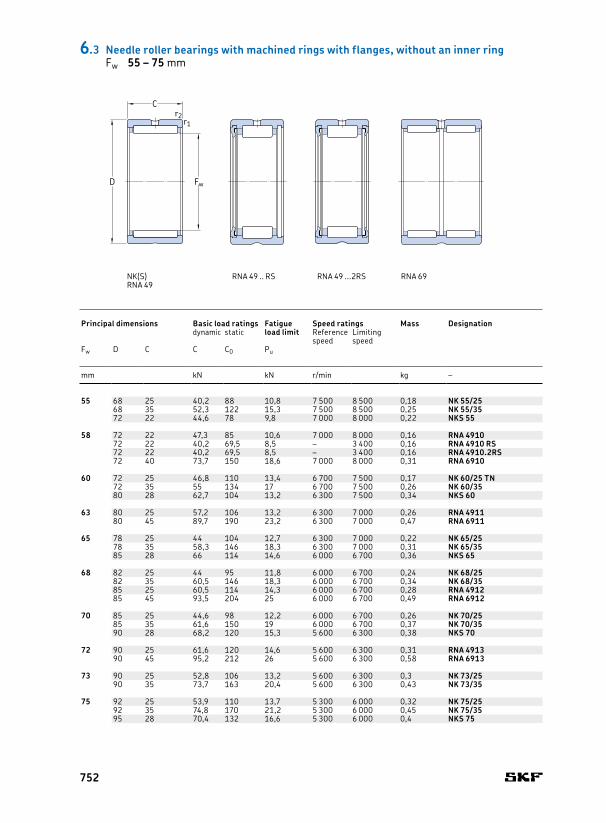
55 68 25 40,2 88 10,8 7 500 8 500 0,18 NK 55/25 55 0,6 64 0,6 CR 55x68x8 HMS5 RG68 35 52,3 122 15,3 7 500 8 500 0,25 NK 55/35 0,6 64 0,6 CR 55x68x8 HMS5 RG72 22 44,6 78 9,8 7 000 8 000 0,22 NKS 55 1 67 1 CR 55x72x8 HMS5 RG
58 72 22 47,3 85 10,6 7 000 8 000 0,16 RNA 4910 58 0,6 68 0,6 CR 58x72x8 HMS5 RG72 22 40,2 69,5 8,5 – 3 400 0,16 RNA 4910 RS 0,6 68 0,6 –72 22 40,2 69,5 8,5 – 3 400 0,16 RNA 4910.2RS 0,6 68 0,6 –72 40 73,7 150 18,6 7 000 8 000 0,31 RNA 6910 0,6 68 0,6 CR 58x72x8 HMS5 RG
60 72 25 46,8 110 13,4 6 700 7 500 0,17 NK 60/25 TN 60 0,6 68 0,6 CR 60x72x8 HMS5 RG72 35 55 134 17 6 700 7 500 0,26 NK 60/35 0,6 68 0,6 CR 60x72x8 HMS5 RG80 28 62,7 104 13,2 6 300 7 500 0,34 NKS 60 1,1 73,5 1 CR 60x80x8 HMS5 RG
63 80 25 57,2 106 13,2 6 300 7 000 0,26 RNA 4911 63 1 75 1 CR 63x80x8 CRW1 R80 45 89,7 190 23,2 6 300 7 000 0,47 RNA 6911 1 75 1 CR 63x80x8 CRW1 R
65 78 25 44 104 12,7 6 300 7 000 0,22 NK 65/25 65 0,6 74 0,6 –78 35 58,3 146 18,3 6 300 7 000 0,31 NK 65/35 0,6 74 0,6 –85 28 66 114 14,6 6 000 6 700 0,36 NKS 65 1,1 78,5 1 CR 65x85x8 HMS5 RG
68 82 25 44 95 11,8 6 000 6 700 0,24 NK 68/25 68 0,6 78 0,6 –82 35 60,5 146 18,3 6 000 6 700 0,34 NK 68/35 0,6 78 0,6 –85 25 60,5 114 14,3 6 000 6 700 0,28 RNA 4912 1 80 1 –85 45 93,5 204 25 6 000 6 700 0,49 RNA 6912 1 80 1 CR 68x85x8 CRW1 R
70 85 25 44,6 98 12,2 6 000 6 700 0,26 NK 70/25 70 0,6 81 0,6 CR 70x85x8 HMS5 RG85 35 61,6 150 19 6 000 6 700 0,37 NK 70/35 0,6 81 0,6 CR 70x85x8 HMS5 RG90 28 68,2 120 15,3 5 600 6 300 0,38 NKS 70 1,1 83,5 1 CR 70x90x10 HMS5 RG
72 90 25 61,6 120 14,6 5 600 6 300 0,31 RNA 4913 72 1 85 1 CR 72x90x10 HMS5 RG90 45 95,2 212 26 5 600 6 300 0,58 RNA 6913 1 85 1 CR 72x90x10 HMS5 RG
73 90 25 52,8 106 13,2 5 600 6 300 0,3 NK 73/25 73 1 85 1 –90 35 73,7 163 20,4 5 600 6 300 0,43 NK 73/35 1 85 1 –
75 92 25 53,9 110 13,7 5 300 6 000 0,32 NK 75/25 75 1 87 1 CR 73x92x11.1 CRWH1 R92 35 74,8 170 21,2 5 300 6 000 0,45 NK 75/35 1 87 1 CR 73x92x11.1 CRWH1 R95 28 70,4 132 16,6 5 300 6 000 0,4 NKS 75 1,1 88,5 1 CR 75x95x10 HMS5 RG
6.3 Needle roller bearings with machined rings with flanges, without an inner ringFw 55 – 75 mm
Principal dimensions Basic load ratings Fatigue
load limitSpeed ratings Mass Designation Dimensions Abutment and fillet
dimensionsAppropriate seal1)
dynamic static Reference speed
Limiting speed
Designation
Fw D C C C0 Pu Fw r1,2 Da ramin. max. max.
mm kN kN r/min kg – mm mm –
Fw
C
D
r2r1
NK(S) RNA 49 .. RS RNA 49 ...2RS RNA 69RNA 49
752

55 68 25 40,2 88 10,8 7 500 8 500 0,18 NK 55/25 55 0,6 64 0,6 CR 55x68x8 HMS5 RG68 35 52,3 122 15,3 7 500 8 500 0,25 NK 55/35 0,6 64 0,6 CR 55x68x8 HMS5 RG72 22 44,6 78 9,8 7 000 8 000 0,22 NKS 55 1 67 1 CR 55x72x8 HMS5 RG
58 72 22 47,3 85 10,6 7 000 8 000 0,16 RNA 4910 58 0,6 68 0,6 CR 58x72x8 HMS5 RG72 22 40,2 69,5 8,5 – 3 400 0,16 RNA 4910 RS 0,6 68 0,6 –72 22 40,2 69,5 8,5 – 3 400 0,16 RNA 4910.2RS 0,6 68 0,6 –72 40 73,7 150 18,6 7 000 8 000 0,31 RNA 6910 0,6 68 0,6 CR 58x72x8 HMS5 RG
60 72 25 46,8 110 13,4 6 700 7 500 0,17 NK 60/25 TN 60 0,6 68 0,6 CR 60x72x8 HMS5 RG72 35 55 134 17 6 700 7 500 0,26 NK 60/35 0,6 68 0,6 CR 60x72x8 HMS5 RG80 28 62,7 104 13,2 6 300 7 500 0,34 NKS 60 1,1 73,5 1 CR 60x80x8 HMS5 RG
63 80 25 57,2 106 13,2 6 300 7 000 0,26 RNA 4911 63 1 75 1 CR 63x80x8 CRW1 R80 45 89,7 190 23,2 6 300 7 000 0,47 RNA 6911 1 75 1 CR 63x80x8 CRW1 R
65 78 25 44 104 12,7 6 300 7 000 0,22 NK 65/25 65 0,6 74 0,6 –78 35 58,3 146 18,3 6 300 7 000 0,31 NK 65/35 0,6 74 0,6 –85 28 66 114 14,6 6 000 6 700 0,36 NKS 65 1,1 78,5 1 CR 65x85x8 HMS5 RG
68 82 25 44 95 11,8 6 000 6 700 0,24 NK 68/25 68 0,6 78 0,6 –82 35 60,5 146 18,3 6 000 6 700 0,34 NK 68/35 0,6 78 0,6 –85 25 60,5 114 14,3 6 000 6 700 0,28 RNA 4912 1 80 1 –85 45 93,5 204 25 6 000 6 700 0,49 RNA 6912 1 80 1 CR 68x85x8 CRW1 R
70 85 25 44,6 98 12,2 6 000 6 700 0,26 NK 70/25 70 0,6 81 0,6 CR 70x85x8 HMS5 RG85 35 61,6 150 19 6 000 6 700 0,37 NK 70/35 0,6 81 0,6 CR 70x85x8 HMS5 RG90 28 68,2 120 15,3 5 600 6 300 0,38 NKS 70 1,1 83,5 1 CR 70x90x10 HMS5 RG
72 90 25 61,6 120 14,6 5 600 6 300 0,31 RNA 4913 72 1 85 1 CR 72x90x10 HMS5 RG90 45 95,2 212 26 5 600 6 300 0,58 RNA 6913 1 85 1 CR 72x90x10 HMS5 RG
73 90 25 52,8 106 13,2 5 600 6 300 0,3 NK 73/25 73 1 85 1 –90 35 73,7 163 20,4 5 600 6 300 0,43 NK 73/35 1 85 1 –
75 92 25 53,9 110 13,7 5 300 6 000 0,32 NK 75/25 75 1 87 1 CR 73x92x11.1 CRWH1 R92 35 74,8 170 21,2 5 300 6 000 0,45 NK 75/35 1 87 1 CR 73x92x11.1 CRWH1 R95 28 70,4 132 16,6 5 300 6 000 0,4 NKS 75 1,1 88,5 1 CR 75x95x10 HMS5 RG
6 .3
Principal dimensions Basic load ratings Fatigue
load limitSpeed ratings Mass Designation Dimensions Abutment and fillet
dimensionsAppropriate seal1)
dynamic static Reference speed
Limiting speed
Designation
Fw D C C C0 Pu Fw r1,2 Da ramin. max. max.
mm kN kN r/min kg – mm mm –
1) For additional information, visit skf.com/seals.
Da
ra
753

80 95 25 56,1 127 15,6 5 000 5 600 0,3 NK 80/25 80 1 90 1 CR 80x95x10 HMS5 RG95 35 76,5 190 24 5 000 5 600 0,43 NK 80/35 1 90 1 CR 80x95x10 HMS5 RG100 30 84,2 163 20,8 5 000 5 600 0,46 RNA 4914 1 95 1 CR 80x100x10 HMS5 RG100 54 128 285 36 5 000 5 600 0,86 RNA 6914 1 95 1 CR 80x100x10 HMS5 RG
85 105 25 69,3 132 16,6 4 800 5 300 0,43 NK 85/25 85 1 100 1 CR 85x105x12 HMS5 RG105 30 84,2 170 21,6 4 800 5 300 0,49 RNA 4915 1 100 1 CR 85x105x12 HMS5 RG105 35 96,8 200 26 4 800 5 300 0,6 NK 85/35 1 100 1 CR 85x105x12 HMS5 RG105 54 130 290 37,5 4 800 5 300 0,94 RNA 6915 1 100 1 CR 85x105x12 HMS5 RG
90 110 25 72,1 140 18 4 500 5 000 0,45 NK 90/25 90 1 105 1 CR 90x110x10 HMS5 RG110 30 88 183 23,2 4 500 5 000 0,52 RNA 4916 1 105 1 CR 90x110x10 HMS5 RG110 35 101 216 28 4 500 5 000 0,63 NK 90/35 1 105 1 CR 90x110x10 HMS5 RG110 54 134 315 40 4 500 5 000 0,99 RNA 6916 1 105 1 CR 90x110x10 HMS5 RG
95 115 26 73,7 146 18,6 4 300 4 800 0,49 NK 95/26 95 1 110 1 CR 95x115x12 HMS5 RG115 36 105 232 30 4 300 4 800 0,68 NK 95/36 1 110 1 CR 95x115x12 HMS5 RG
100 120 26 76,5 156 19,6 4 000 4 500 0,52 NK 100/26 100 1 115 1 CR 100x120x10 HMS5 RG120 35 108 250 31 4 000 4 500 0,66 RNA 4917 1,1 113,5 1 CR 100x120x10 HMS5 RG120 36 108 250 31 4 000 4 500 0,72 NK 100/36 1 115 1 CR 100x120x10 HMS5 RG120 63 165 425 53 4 000 4 500 1,2 RNA 6917 1,1 113,5 1 CR 100x120x10 HMS5 RG
105 125 26 78,1 166 20,4 3 800 4 300 0,54 NK 105/26 105 1 120 1 CR 105x125x13 HMS4 R125 35 112 265 32,5 3 800 4 300 0,75 RNA 4918 1,1 118,5 1 CR 105x125x13 HMS4 R125 36 112 265 32,5 3 800 4 300 0,71 NK 105/36 1 120 1 CR 105x125x13 HMS4 R125 63 172 450 55 3 800 4 300 1,35 RNA 6918 1,1 118,5 1 CR 105x125x13 HMS4 R
110 130 30 96,8 220 27 3 600 4 000 0,65 NK 110/30 110 1,1 123,5 1 CR 110x130x12 HMS5 RG130 35 114 270 33,5 3 600 4 000 0,72 RNA 4919 1,1 123,5 1 CR 110x130x12 HMS5 RG130 40 123 305 37,5 3 600 4 000 0,83 NK 110/40 1,1 123,5 1 CR 110x130x12 HMS5 RG130 63 172 465 56 3 600 4 000 1,45 RNA 6919 1,1 123,5 1 CR 110x130x12 HMS5 RG
115 140 40 125 280 34 3 400 4 000 1,15 RNA 4920 115 1,1 133,5 1 CR 115x140x12 HMS5 RG
120 140 30 93,5 232 27 3 400 3 800 0,66 RNA 4822 120 1 135 1 CR 120x140x12 HMS5 RG
125 150 40 130 300 35,5 3 200 3 600 1,25 RNA 4922 125 1,1 143,5 1 CR 125x150x12 HMS5 RG
130 150 30 99 255 29 3 200 3 600 0,73 RNA 4824 130 1 145 1 CR 130x150x10 CRSA1 R
6.3 Needle roller bearings with machined rings with flanges, without an inner ringFw 80 – 130 mm
Principal dimensions Basic load ratings Fatigue
load limitSpeed ratings Mass Designation Dimensions Abutment and fillet
dimensionsAppropriate seal1)
dynamic static Reference speed
Limiting speed
Designation
Fw D C C C0 Pu Fw r1,2 Da ramin. max. max.
mm kN kN r/min kg – mm mm –
Fw
C
D
r2r1
NK RNA 69RNA 48RNA 49
754
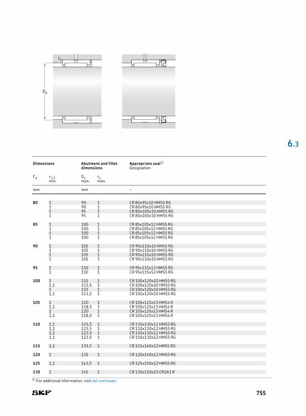
80 95 25 56,1 127 15,6 5 000 5 600 0,3 NK 80/25 80 1 90 1 CR 80x95x10 HMS5 RG95 35 76,5 190 24 5 000 5 600 0,43 NK 80/35 1 90 1 CR 80x95x10 HMS5 RG100 30 84,2 163 20,8 5 000 5 600 0,46 RNA 4914 1 95 1 CR 80x100x10 HMS5 RG100 54 128 285 36 5 000 5 600 0,86 RNA 6914 1 95 1 CR 80x100x10 HMS5 RG
85 105 25 69,3 132 16,6 4 800 5 300 0,43 NK 85/25 85 1 100 1 CR 85x105x12 HMS5 RG105 30 84,2 170 21,6 4 800 5 300 0,49 RNA 4915 1 100 1 CR 85x105x12 HMS5 RG105 35 96,8 200 26 4 800 5 300 0,6 NK 85/35 1 100 1 CR 85x105x12 HMS5 RG105 54 130 290 37,5 4 800 5 300 0,94 RNA 6915 1 100 1 CR 85x105x12 HMS5 RG
90 110 25 72,1 140 18 4 500 5 000 0,45 NK 90/25 90 1 105 1 CR 90x110x10 HMS5 RG110 30 88 183 23,2 4 500 5 000 0,52 RNA 4916 1 105 1 CR 90x110x10 HMS5 RG110 35 101 216 28 4 500 5 000 0,63 NK 90/35 1 105 1 CR 90x110x10 HMS5 RG110 54 134 315 40 4 500 5 000 0,99 RNA 6916 1 105 1 CR 90x110x10 HMS5 RG
95 115 26 73,7 146 18,6 4 300 4 800 0,49 NK 95/26 95 1 110 1 CR 95x115x12 HMS5 RG115 36 105 232 30 4 300 4 800 0,68 NK 95/36 1 110 1 CR 95x115x12 HMS5 RG
100 120 26 76,5 156 19,6 4 000 4 500 0,52 NK 100/26 100 1 115 1 CR 100x120x10 HMS5 RG120 35 108 250 31 4 000 4 500 0,66 RNA 4917 1,1 113,5 1 CR 100x120x10 HMS5 RG120 36 108 250 31 4 000 4 500 0,72 NK 100/36 1 115 1 CR 100x120x10 HMS5 RG120 63 165 425 53 4 000 4 500 1,2 RNA 6917 1,1 113,5 1 CR 100x120x10 HMS5 RG
105 125 26 78,1 166 20,4 3 800 4 300 0,54 NK 105/26 105 1 120 1 CR 105x125x13 HMS4 R125 35 112 265 32,5 3 800 4 300 0,75 RNA 4918 1,1 118,5 1 CR 105x125x13 HMS4 R125 36 112 265 32,5 3 800 4 300 0,71 NK 105/36 1 120 1 CR 105x125x13 HMS4 R125 63 172 450 55 3 800 4 300 1,35 RNA 6918 1,1 118,5 1 CR 105x125x13 HMS4 R
110 130 30 96,8 220 27 3 600 4 000 0,65 NK 110/30 110 1,1 123,5 1 CR 110x130x12 HMS5 RG130 35 114 270 33,5 3 600 4 000 0,72 RNA 4919 1,1 123,5 1 CR 110x130x12 HMS5 RG130 40 123 305 37,5 3 600 4 000 0,83 NK 110/40 1,1 123,5 1 CR 110x130x12 HMS5 RG130 63 172 465 56 3 600 4 000 1,45 RNA 6919 1,1 123,5 1 CR 110x130x12 HMS5 RG
115 140 40 125 280 34 3 400 4 000 1,15 RNA 4920 115 1,1 133,5 1 CR 115x140x12 HMS5 RG
120 140 30 93,5 232 27 3 400 3 800 0,66 RNA 4822 120 1 135 1 CR 120x140x12 HMS5 RG
125 150 40 130 300 35,5 3 200 3 600 1,25 RNA 4922 125 1,1 143,5 1 CR 125x150x12 HMS5 RG
130 150 30 99 255 29 3 200 3 600 0,73 RNA 4824 130 1 145 1 CR 130x150x10 CRSA1 R
6 .3
Principal dimensions Basic load ratings Fatigue
load limitSpeed ratings Mass Designation Dimensions Abutment and fillet
dimensionsAppropriate seal1)
dynamic static Reference speed
Limiting speed
Designation
Fw D C C C0 Pu Fw r1,2 Da ramin. max. max.
mm kN kN r/min kg – mm mm –
1) For additional information, visit skf.com/seals.
Da
ra
755

135 165 45 176 405 46,5 3 000 3 400 1,85 RNA 4924 135 1,1 158,5 1 CR 135x165x14 HMSA7 R
145 165 35 119 325 36,5 2 800 3 200 0,99 RNA 4826 145 1,1 158,5 1 –
150 180 50 198 480 54 2 600 3 000 2,2 RNA 4926 150 1,5 172 1,5 CR 150x180x12 HMS5 RG
155 175 35 121 345 37,5 2 600 3 000 0,97 RNA 4828 155 1,1 168,5 1 –
160 190 50 205 510 57 2 400 2 800 2,35 RNA 4928 160 1,5 182 1,5 CR 160x190x15 HMS5 RG
165 190 40 147 415 46,5 2 400 2 800 1,6 RNA 4830 165 1,1 183,5 1 CR 165x190x15 HMS5 RG
175 200 40 157 450 49 2 200 2 600 1,7 RNA 4832 175 1,1 193,5 1 CR 175x200x15 HMS5 RG
185 215 45 179 520 56 2 200 2 400 2,55 RNA 4834 185 1,1 208,5 1 CR 185x215x15 HMS42 R
195 225 45 190 570 60 2 000 2 400 2,7 RNA 4836 195 1,1 218,5 1 –
210 240 50 220 710 73,5 1 900 2 200 3,2 RNA 4838 210 1,5 232 1,5 CR 210x240x15 HMS5 RG
220 250 50 224 735 75 1 800 2 000 3,35 RNA 4840 220 1,5 242 1,5 CR 220x250x15 HMS5 RG
240 270 50 238 815 81,5 1 700 1 900 3,6 RNA 4844 240 1,5 262 1,5 CR 240x270x15 HMS5 RG
265 300 60 347 1119,999 110 1 500 1 700 5,4 RNA 4848 265 2 291 2 –2)
285 320 60 358 1199,999 114 1 400 1 500 5,8 RNA 4852 285 2 311 2 CR 285x320x16 HDS2 R
305 350 69 429 1319,999 125 1 300 1 400 9,3 RNA 4856 305 2 341 2 –2)
330 380 80 594 1799,999 166 1 100 1 300 12,5 RNA 4860 330 2,1 369 2 –2)
350 400 80 605 1899,999 170 1 100 1 200 13,5 RNA 4864 350 2,1 389 2 –
370 420 80 616 1959,999 176 1 000 1 200 14 RNA 4868 370 2,1 409 2 –
390 440 80 627 2039,999 180 950 1 100 15 RNA 4872 390 2,1 429 2 –2)
415 480 100 968 3 000 260 900 1 000 26 RNA 4876 415 2,1 469 2 –2)
6.3 Needle roller bearings with machined rings with flanges, without an inner ringFw 135 – 415 mm
Principal dimensions Basic load ratings Fatigue
load limitSpeed ratings Mass Designation Dimensions Abutment and fillet
dimensionsAppropriate seal1)
dynamic static Reference speed
Limiting speed
Designation
Fw D C C C0 Pu Fw r1,2 Da ramin. max. max.
mm kN kN r/min kg – mm mm –
Fw
C
D
r2r1
756

135 165 45 176 405 46,5 3 000 3 400 1,85 RNA 4924 135 1,1 158,5 1 CR 135x165x14 HMSA7 R
145 165 35 119 325 36,5 2 800 3 200 0,99 RNA 4826 145 1,1 158,5 1 –
150 180 50 198 480 54 2 600 3 000 2,2 RNA 4926 150 1,5 172 1,5 CR 150x180x12 HMS5 RG
155 175 35 121 345 37,5 2 600 3 000 0,97 RNA 4828 155 1,1 168,5 1 –
160 190 50 205 510 57 2 400 2 800 2,35 RNA 4928 160 1,5 182 1,5 CR 160x190x15 HMS5 RG
165 190 40 147 415 46,5 2 400 2 800 1,6 RNA 4830 165 1,1 183,5 1 CR 165x190x15 HMS5 RG
175 200 40 157 450 49 2 200 2 600 1,7 RNA 4832 175 1,1 193,5 1 CR 175x200x15 HMS5 RG
185 215 45 179 520 56 2 200 2 400 2,55 RNA 4834 185 1,1 208,5 1 CR 185x215x15 HMS42 R
195 225 45 190 570 60 2 000 2 400 2,7 RNA 4836 195 1,1 218,5 1 –
210 240 50 220 710 73,5 1 900 2 200 3,2 RNA 4838 210 1,5 232 1,5 CR 210x240x15 HMS5 RG
220 250 50 224 735 75 1 800 2 000 3,35 RNA 4840 220 1,5 242 1,5 CR 220x250x15 HMS5 RG
240 270 50 238 815 81,5 1 700 1 900 3,6 RNA 4844 240 1,5 262 1,5 CR 240x270x15 HMS5 RG
265 300 60 347 1119,999 110 1 500 1 700 5,4 RNA 4848 265 2 291 2 –2)
285 320 60 358 1199,999 114 1 400 1 500 5,8 RNA 4852 285 2 311 2 CR 285x320x16 HDS2 R
305 350 69 429 1319,999 125 1 300 1 400 9,3 RNA 4856 305 2 341 2 –2)
330 380 80 594 1799,999 166 1 100 1 300 12,5 RNA 4860 330 2,1 369 2 –2)
350 400 80 605 1899,999 170 1 100 1 200 13,5 RNA 4864 350 2,1 389 2 –
370 420 80 616 1959,999 176 1 000 1 200 14 RNA 4868 370 2,1 409 2 –
390 440 80 627 2039,999 180 950 1 100 15 RNA 4872 390 2,1 429 2 –2)
415 480 100 968 3 000 260 900 1 000 26 RNA 4876 415 2,1 469 2 –2)
6 .3
Principal dimensions Basic load ratings Fatigue
load limitSpeed ratings Mass Designation Dimensions Abutment and fillet
dimensionsAppropriate seal1)
dynamic static Reference speed
Limiting speed
Designation
Fw D C C C0 Pu Fw r1,2 Da ramin. max. max.
mm kN kN r/min kg – mm mm –
1) For additional information, visit skf.com/seals.2) Contact SKF for appropriate seal.
Da
ra
757
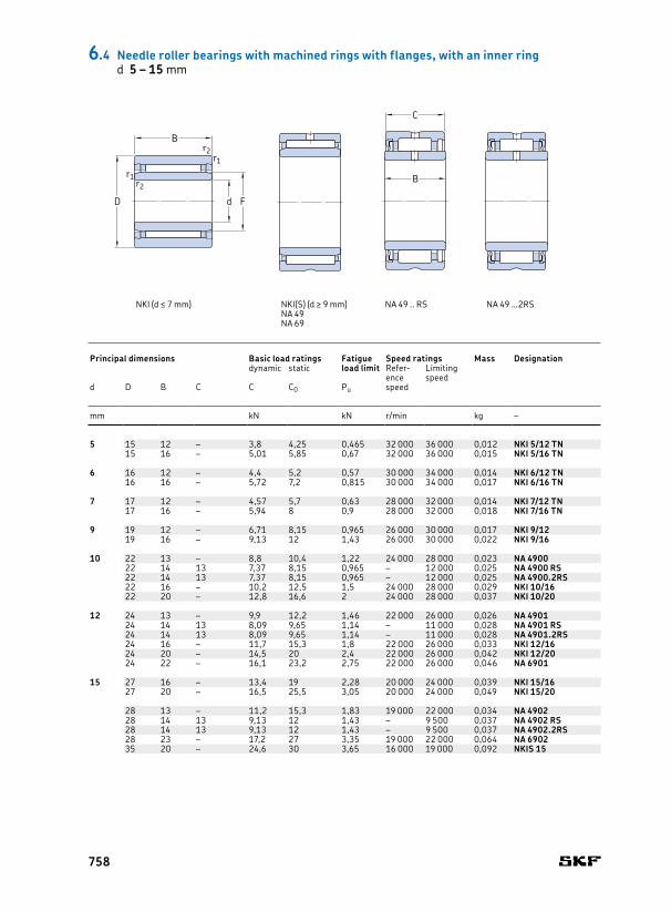
5 15 12 – 3,8 4,25 0,465 32 000 36 000 0,012 NKI 5/12 TN 5 8 0,3 1,5 7 13 0,315 16 – 5,01 5,85 0,67 32 000 36 000 0,015 NKI 5/16 TN 8 0,3 2 7 13 0,3
6 16 12 – 4,4 5,2 0,57 30 000 34 000 0,014 NKI 6/12 TN 6 9 0,3 1,5 8 14 0,316 16 – 5,72 7,2 0,815 30 000 34 000 0,017 NKI 6/16 TN 9 0,3 2 8 14 0,3
7 17 12 – 4,57 5,7 0,63 28 000 32 000 0,014 NKI 7/12 TN 7 10 0,3 1,5 9 15 0,317 16 – 5,94 8 0,9 28 000 32 000 0,018 NKI 7/16 TN 10 0,3 2 9 15 0,3
9 19 12 – 6,71 8,15 0,965 26 000 30 000 0,017 NKI 9/12 9 12 0,3 1,5 11 17 0,319 16 – 9,13 12 1,43 26 000 30 000 0,022 NKI 9/16 12 0,3 2 11 17 0,3
10 22 13 – 8,8 10,4 1,22 24 000 28 000 0,023 NA 4900 10 14 0,3 0,5 12 20 0,322 14 13 7,37 8,15 0,965 – 12 000 0,025 NA 4900 RS 14 0,3 0,5 12 20 0,322 14 13 7,37 8,15 0,965 – 12 000 0,025 NA 4900.2RS 14 0,3 0,5 12 20 0,322 16 – 10,2 12,5 1,5 24 000 28 000 0,029 NKI 10/16 14 0,3 0,5 12 20 0,322 20 – 12,8 16,6 2 24 000 28 000 0,037 NKI 10/20 14 0,3 0,5 12 20 0,3
12 24 13 – 9,9 12,2 1,46 22 000 26 000 0,026 NA 4901 12 16 0,3 0,5 14 22 0,324 14 13 8,09 9,65 1,14 – 11 000 0,028 NA 4901 RS 16 0,3 0,5 14 22 0,324 14 13 8,09 9,65 1,14 – 11 000 0,028 NA 4901.2RS 16 0,3 0,5 14 22 0,324 16 – 11,7 15,3 1,8 22 000 26 000 0,033 NKI 12/16 16 0,3 0,5 14 22 0,324 20 – 14,5 20 2,4 22 000 26 000 0,042 NKI 12/20 16 0,3 0,5 14 22 0,324 22 – 16,1 23,2 2,75 22 000 26 000 0,046 NA 6901 16 0,3 1 14 22 0,3
15 27 16 – 13,4 19 2,28 20 000 24 000 0,039 NKI 15/16 15 19 0,3 0,5 17 25 0,327 20 – 16,5 25,5 3,05 20 000 24 000 0,049 NKI 15/20 19 0,3 0,5 17 25 0,3
28 13 – 11,2 15,3 1,83 19 000 22 000 0,034 NA 4902 20 0,3 0,5 17 26 0,328 14 13 9,13 12 1,43 – 9 500 0,037 NA 4902 RS 20 0,3 0,5 17 26 0,328 14 13 9,13 12 1,43 – 9 500 0,037 NA 4902.2RS 20 0,3 0,5 17 26 0,328 23 – 17,2 27 3,35 19 000 22 000 0,064 NA 6902 20 0,3 1 17 26 0,335 20 – 24,6 30 3,65 16 000 19 000 0,092 NKIS 15 22 0,6 0,5 19 31 0,6
C
B
d
B
r1
F
r1
r2
r2
D
NKI (d ≤ 7 mm) NKI(S) (d ≥ 9 mm) NA 49 .. RS NA 49 …2RSNA 49NA 69
6.4 Needle roller bearings with machined rings with flanges, with an inner ringd 5 – 15 mm
Principal dimensions Basic load ratings Fatigue
load limitSpeed ratings Mass Designation Dimensions Abutment and fillet dimensions
dynamic static Reference speed
Limiting speed
d D B C C C0 Pu d F r1,2 s1) da Da ramin. min. max. max.
mm kN kN r/min kg – mm mm
758

5 15 12 – 3,8 4,25 0,465 32 000 36 000 0,012 NKI 5/12 TN 5 8 0,3 1,5 7 13 0,315 16 – 5,01 5,85 0,67 32 000 36 000 0,015 NKI 5/16 TN 8 0,3 2 7 13 0,3
6 16 12 – 4,4 5,2 0,57 30 000 34 000 0,014 NKI 6/12 TN 6 9 0,3 1,5 8 14 0,316 16 – 5,72 7,2 0,815 30 000 34 000 0,017 NKI 6/16 TN 9 0,3 2 8 14 0,3
7 17 12 – 4,57 5,7 0,63 28 000 32 000 0,014 NKI 7/12 TN 7 10 0,3 1,5 9 15 0,317 16 – 5,94 8 0,9 28 000 32 000 0,018 NKI 7/16 TN 10 0,3 2 9 15 0,3
9 19 12 – 6,71 8,15 0,965 26 000 30 000 0,017 NKI 9/12 9 12 0,3 1,5 11 17 0,319 16 – 9,13 12 1,43 26 000 30 000 0,022 NKI 9/16 12 0,3 2 11 17 0,3
10 22 13 – 8,8 10,4 1,22 24 000 28 000 0,023 NA 4900 10 14 0,3 0,5 12 20 0,322 14 13 7,37 8,15 0,965 – 12 000 0,025 NA 4900 RS 14 0,3 0,5 12 20 0,322 14 13 7,37 8,15 0,965 – 12 000 0,025 NA 4900.2RS 14 0,3 0,5 12 20 0,322 16 – 10,2 12,5 1,5 24 000 28 000 0,029 NKI 10/16 14 0,3 0,5 12 20 0,322 20 – 12,8 16,6 2 24 000 28 000 0,037 NKI 10/20 14 0,3 0,5 12 20 0,3
12 24 13 – 9,9 12,2 1,46 22 000 26 000 0,026 NA 4901 12 16 0,3 0,5 14 22 0,324 14 13 8,09 9,65 1,14 – 11 000 0,028 NA 4901 RS 16 0,3 0,5 14 22 0,324 14 13 8,09 9,65 1,14 – 11 000 0,028 NA 4901.2RS 16 0,3 0,5 14 22 0,324 16 – 11,7 15,3 1,8 22 000 26 000 0,033 NKI 12/16 16 0,3 0,5 14 22 0,324 20 – 14,5 20 2,4 22 000 26 000 0,042 NKI 12/20 16 0,3 0,5 14 22 0,324 22 – 16,1 23,2 2,75 22 000 26 000 0,046 NA 6901 16 0,3 1 14 22 0,3
15 27 16 – 13,4 19 2,28 20 000 24 000 0,039 NKI 15/16 15 19 0,3 0,5 17 25 0,327 20 – 16,5 25,5 3,05 20 000 24 000 0,049 NKI 15/20 19 0,3 0,5 17 25 0,3
28 13 – 11,2 15,3 1,83 19 000 22 000 0,034 NA 4902 20 0,3 0,5 17 26 0,328 14 13 9,13 12 1,43 – 9 500 0,037 NA 4902 RS 20 0,3 0,5 17 26 0,328 14 13 9,13 12 1,43 – 9 500 0,037 NA 4902.2RS 20 0,3 0,5 17 26 0,328 23 – 17,2 27 3,35 19 000 22 000 0,064 NA 6902 20 0,3 1 17 26 0,335 20 – 24,6 30 3,65 16 000 19 000 0,092 NKIS 15 22 0,6 0,5 19 31 0,6
6 .4
daDa
ra
ra
1) Permissible axial displacement from the normal position of one bearing ring relative to the other.
Principal dimensions Basic load ratings Fatigue
load limitSpeed ratings Mass Designation Dimensions Abutment and fillet dimensions
dynamic static Reference speed
Limiting speed
d D B C C C0 Pu d F r1,2 s1) da Da ramin. min. max. max.
mm kN kN r/min kg – mm mm
759

17 29 16 – 13,8 20,4 2,45 19 000 22 000 0,042 NKI 17/16 17 21 0,3 0,5 19 27 0,329 20 – 17,2 27 3,35 19 000 22 000 0,053 NKI 17/20 21 0,3 0,5 19 27 0,3
30 13 – 11,4 16,3 1,96 18 000 20 000 0,037 NA 4903 22 0,3 0,5 19 28 0,330 14 13 9,52 12,9 1,53 – 9 000 0,04 NA 4903 RS 22 0,3 0,5 19 28 0,330 14 13 9,52 12,9 1,53 – 9 000 0,04 NA 4903.2RS 22 0,3 0,5 19 28 0,330 23 – 18,7 30,5 3,75 18 000 20 000 0,072 NA 6903 22 0,3 1 19 28 0,337 20 – 26 33,5 4 15 000 17 000 0,098 NKIS 17 24 0,6 0,5 21 33 0,6
20 32 16 – 15,4 24,5 2,9 16 000 19 000 0,048 NKI 20/16 20 24 0,3 0,5 22 30 0,332 20 – 19 32,5 4 16 000 19 000 0,06 NKI 20/20 24 0,3 0,5 22 30 0,3
37 17 – 21,6 28 3,35 15 000 17 000 0,075 NA 4904 25 0,3 0,8 22 35 0,337 18 17 19,4 22,4 2,65 – 7 500 0,08 NA 4904 RS 25 0,3 0,5 22 35 0,337 18 17 19,4 22,4 2,65 – 7 500 0,08 NA 4904.2RS 25 0,3 0,5 22 35 0,337 30 – 35,2 53 6,55 15 000 17 000 0,14 NA 6904 25 0,3 1 22 35 0,342 20 – 28,6 39 4,75 13 000 15 000 0,13 NKIS 20 28 0,6 0,5 24 38 0,6
22 34 16 – 15,7 26 3,1 15 000 17 000 0,052 NKI 22/16 22 26 0,3 0,5 24 32 0,334 20 – 19,4 34,5 4,25 15 000 17 000 0,065 NKI 22/20 26 0,3 0,5 24 32 0,339 17 – 23,3 32 3,9 14 000 15 000 0,08 NA 49/22 28 0,3 0,8 24 37 0,339 30 – 36,9 57 7,2 14 000 15 000 0,15 NA 69/22 28 0,3 0,5 24 37 0,3
25 38 20 – 24,6 42,5 5,2 14 000 15 000 0,08 NKI 25/20 TN 25 29 0,3 1 27 36 0,338 30 – 31,9 60 7,5 14 000 15 000 0,12 NKI 25/30 29 0,3 1,5 27 36 0,3
42 17 – 24,2 34,5 4,15 13 000 15 000 0,088 NA 4905 30 0,3 0,8 27 40 0,342 18 17 21,6 27,5 3,25 – 6 300 0,09 NA 4905 RS 30 0,3 0,5 27 40 0,342 18 17 21,6 27,5 3,25 – 6 300 0,09 NA 4905.2RS 30 0,3 0,5 27 40 0,342 30 – 38 62 7,65 13 000 15 000 0,16 NA 6905 30 0,3 1 27 40 0,347 22 – 34,1 46,5 5,7 12 000 13 000 0,16 NKIS 25 32 0,6 1 29 43 0,6
28 42 20 – 26,4 48 6 12 000 14 000 0,092 NKI 28/20 TN 28 32 0,3 1 30 40 0,342 30 – 34,1 65,5 8,3 12 000 14 000 0,14 NKI 28/30 32 0,3 1,5 30 40 0,345 17 – 25,1 36,5 4,4 12 000 14 000 0,098 NA 49/28 32 0,3 0,8 30 43 0,345 30 – 39,6 65,5 8,3 12 000 14 000 0,18 NA 69/28 32 0,3 1 30 43 0,3
6.4 Needle roller bearings with machined rings with flanges, with an inner ringd 17 – 28 mm
Principal dimensions Basic load ratings Fatigue
load limitSpeed ratings Mass Designation Dimensions Abutment and fillet dimensions
dynamic static Reference speed
Limiting speed
d D B C C C0 Pu d F r1,2 s1) da Da ramin. min. max. max.
mm kN kN r/min kg – mm mm
C
B
NKI(S) NA 49 .. RS NA 49 …2RSNA 49NA 69
d
B
r1
F
r1
r2
r2
D
760
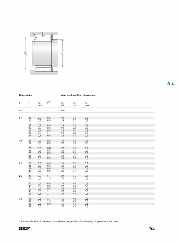
17 29 16 – 13,8 20,4 2,45 19 000 22 000 0,042 NKI 17/16 17 21 0,3 0,5 19 27 0,329 20 – 17,2 27 3,35 19 000 22 000 0,053 NKI 17/20 21 0,3 0,5 19 27 0,3
30 13 – 11,4 16,3 1,96 18 000 20 000 0,037 NA 4903 22 0,3 0,5 19 28 0,330 14 13 9,52 12,9 1,53 – 9 000 0,04 NA 4903 RS 22 0,3 0,5 19 28 0,330 14 13 9,52 12,9 1,53 – 9 000 0,04 NA 4903.2RS 22 0,3 0,5 19 28 0,330 23 – 18,7 30,5 3,75 18 000 20 000 0,072 NA 6903 22 0,3 1 19 28 0,337 20 – 26 33,5 4 15 000 17 000 0,098 NKIS 17 24 0,6 0,5 21 33 0,6
20 32 16 – 15,4 24,5 2,9 16 000 19 000 0,048 NKI 20/16 20 24 0,3 0,5 22 30 0,332 20 – 19 32,5 4 16 000 19 000 0,06 NKI 20/20 24 0,3 0,5 22 30 0,3
37 17 – 21,6 28 3,35 15 000 17 000 0,075 NA 4904 25 0,3 0,8 22 35 0,337 18 17 19,4 22,4 2,65 – 7 500 0,08 NA 4904 RS 25 0,3 0,5 22 35 0,337 18 17 19,4 22,4 2,65 – 7 500 0,08 NA 4904.2RS 25 0,3 0,5 22 35 0,337 30 – 35,2 53 6,55 15 000 17 000 0,14 NA 6904 25 0,3 1 22 35 0,342 20 – 28,6 39 4,75 13 000 15 000 0,13 NKIS 20 28 0,6 0,5 24 38 0,6
22 34 16 – 15,7 26 3,1 15 000 17 000 0,052 NKI 22/16 22 26 0,3 0,5 24 32 0,334 20 – 19,4 34,5 4,25 15 000 17 000 0,065 NKI 22/20 26 0,3 0,5 24 32 0,339 17 – 23,3 32 3,9 14 000 15 000 0,08 NA 49/22 28 0,3 0,8 24 37 0,339 30 – 36,9 57 7,2 14 000 15 000 0,15 NA 69/22 28 0,3 0,5 24 37 0,3
25 38 20 – 24,6 42,5 5,2 14 000 15 000 0,08 NKI 25/20 TN 25 29 0,3 1 27 36 0,338 30 – 31,9 60 7,5 14 000 15 000 0,12 NKI 25/30 29 0,3 1,5 27 36 0,3
42 17 – 24,2 34,5 4,15 13 000 15 000 0,088 NA 4905 30 0,3 0,8 27 40 0,342 18 17 21,6 27,5 3,25 – 6 300 0,09 NA 4905 RS 30 0,3 0,5 27 40 0,342 18 17 21,6 27,5 3,25 – 6 300 0,09 NA 4905.2RS 30 0,3 0,5 27 40 0,342 30 – 38 62 7,65 13 000 15 000 0,16 NA 6905 30 0,3 1 27 40 0,347 22 – 34,1 46,5 5,7 12 000 13 000 0,16 NKIS 25 32 0,6 1 29 43 0,6
28 42 20 – 26,4 48 6 12 000 14 000 0,092 NKI 28/20 TN 28 32 0,3 1 30 40 0,342 30 – 34,1 65,5 8,3 12 000 14 000 0,14 NKI 28/30 32 0,3 1,5 30 40 0,345 17 – 25,1 36,5 4,4 12 000 14 000 0,098 NA 49/28 32 0,3 0,8 30 43 0,345 30 – 39,6 65,5 8,3 12 000 14 000 0,18 NA 69/28 32 0,3 1 30 43 0,3
6 .4
1) Permissible axial displacement from the normal position of one bearing ring relative to the other.
Principal dimensions Basic load ratings Fatigue
load limitSpeed ratings Mass Designation Dimensions Abutment and fillet dimensions
dynamic static Reference speed
Limiting speed
d D B C C C0 Pu d F r1,2 s1) da Da ramin. min. max. max.
mm kN kN r/min kg – mm mm
daDa
ra
ra
761
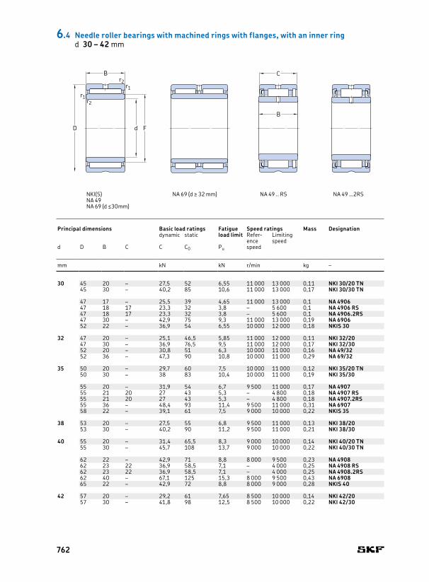
30 45 20 – 27,5 52 6,55 11 000 13 000 0,11 NKI 30/20 TN 30 35 0,3 0,5 32 43 0,345 30 – 40,2 85 10,6 11 000 13 000 0,17 NKI 30/30 TN 35 0,3 1 32 43 0,3
47 17 – 25,5 39 4,65 11 000 13 000 0,1 NA 4906 35 0,3 0,8 32 45 0,347 18 17 23,3 32 3,8 – 5 600 0,1 NA 4906 RS 35 0,3 0,5 32 45 0,347 18 17 23,3 32 3,8 – 5 600 0,1 NA 4906.2RS 35 0,3 0,5 32 45 0,347 30 – 42,9 75 9,3 11 000 13 000 0,19 NA 6906 35 0,3 1 32 45 0,352 22 – 36,9 54 6,55 10 000 12 000 0,18 NKIS 30 37 0,6 1 34 48 0,6
32 47 20 – 25,1 46,5 5,85 11 000 12 000 0,11 NKI 32/20 32 37 0,3 0,5 34 45 0,347 30 – 36,9 76,5 9,5 11 000 12 000 0,17 NKI 32/30 37 0,3 1 34 45 0,352 20 – 30,8 51 6,3 10 000 11 000 0,16 NA 49/32 40 0,6 0,8 36 48 0,652 36 – 47,3 90 10,8 10 000 11 000 0,29 NA 69/32 40 0,6 0,5 36 48 0,6
35 50 20 – 29,7 60 7,5 10 000 11 000 0,12 NKI 35/20 TN 35 40 0,3 0,5 37 48 0,350 30 – 38 83 10,4 10 000 11 000 0,19 NKI 35/30 40 0,3 1 37 48 0,3
55 20 – 31,9 54 6,7 9 500 11 000 0,17 NA 4907 42 0,6 0,8 39 51 0,655 21 20 27 43 5,3 – 4 800 0,18 NA 4907 RS 42 0,6 0,5 39 51 0,655 21 20 27 43 5,3 – 4 800 0,18 NA 4907.2RS 42 0,6 0,5 39 51 0,655 36 – 48,4 93 11,4 9 500 11 000 0,31 NA 6907 42 0,6 0,5 39 51 0,658 22 – 39,1 61 7,5 9 000 10 000 0,22 NKIS 35 43 0,6 0,5 39 53 0,6
38 53 20 – 27,5 55 6,8 9 500 11 000 0,13 NKI 38/20 38 43 0,3 0,5 40 51 0,353 30 – 40,2 90 11,2 9 500 11 000 0,21 NKI 38/30 43 0,3 1 40 51 0,3
40 55 20 – 31,4 65,5 8,3 9 000 10 000 0,14 NKI 40/20 TN 40 45 0,3 0,5 42 53 0,355 30 – 45,7 108 13,7 9 000 10 000 0,22 NKI 40/30 TN 45 0,3 1 42 53 0,3
62 22 – 42,9 71 8,8 8 000 9 500 0,23 NA 4908 48 0,6 1 44 58 0,662 23 22 36,9 58,5 7,1 – 4 000 0,25 NA 4908 RS 48 0,6 0,5 44 58 0,662 23 22 36,9 58,5 7,1 – 4 000 0,25 NA 4908.2RS 48 0,6 0,5 44 58 0,662 40 – 67,1 125 15,3 8 000 9 500 0,43 NA 6908 48 0,6 0,5 44 58 0,665 22 – 42,9 72 8,8 8 000 9 000 0,28 NKIS 40 50 1 0,5 45 60 1
42 57 20 – 29,2 61 7,65 8 500 10 000 0,14 NKI 42/20 42 47 0,3 0,5 44 55 0,357 30 – 41,8 98 12,5 8 500 10 000 0,22 NKI 42/30 47 0,3 1 44 55 0,3
d
B
r1
F
r1
r2
r2
D
6.4 Needle roller bearings with machined rings with flanges, with an inner ringd 30 – 42 mm
Principal dimensions Basic load ratings Fatigue
load limitSpeed ratings Mass Designation Dimensions Abutment and fillet dimensions
dynamic static Reference speed
Limiting speed
d D B C C C0 Pu d F r1,2 s1) da Da ramin. min. max. max.
mm kN kN r/min kg – mm mm
C
B
NKI(S) NA 69 (d ≥ 32 mm) NA 49 .. RS NA 49 …2RSNA 49NA 69 (d ≤30mm)
762
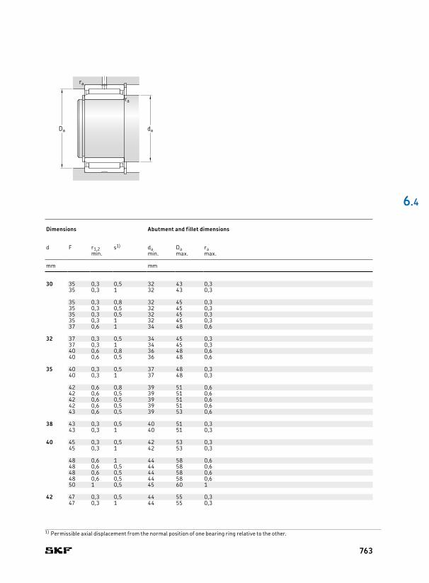
30 45 20 – 27,5 52 6,55 11 000 13 000 0,11 NKI 30/20 TN 30 35 0,3 0,5 32 43 0,345 30 – 40,2 85 10,6 11 000 13 000 0,17 NKI 30/30 TN 35 0,3 1 32 43 0,3
47 17 – 25,5 39 4,65 11 000 13 000 0,1 NA 4906 35 0,3 0,8 32 45 0,347 18 17 23,3 32 3,8 – 5 600 0,1 NA 4906 RS 35 0,3 0,5 32 45 0,347 18 17 23,3 32 3,8 – 5 600 0,1 NA 4906.2RS 35 0,3 0,5 32 45 0,347 30 – 42,9 75 9,3 11 000 13 000 0,19 NA 6906 35 0,3 1 32 45 0,352 22 – 36,9 54 6,55 10 000 12 000 0,18 NKIS 30 37 0,6 1 34 48 0,6
32 47 20 – 25,1 46,5 5,85 11 000 12 000 0,11 NKI 32/20 32 37 0,3 0,5 34 45 0,347 30 – 36,9 76,5 9,5 11 000 12 000 0,17 NKI 32/30 37 0,3 1 34 45 0,352 20 – 30,8 51 6,3 10 000 11 000 0,16 NA 49/32 40 0,6 0,8 36 48 0,652 36 – 47,3 90 10,8 10 000 11 000 0,29 NA 69/32 40 0,6 0,5 36 48 0,6
35 50 20 – 29,7 60 7,5 10 000 11 000 0,12 NKI 35/20 TN 35 40 0,3 0,5 37 48 0,350 30 – 38 83 10,4 10 000 11 000 0,19 NKI 35/30 40 0,3 1 37 48 0,3
55 20 – 31,9 54 6,7 9 500 11 000 0,17 NA 4907 42 0,6 0,8 39 51 0,655 21 20 27 43 5,3 – 4 800 0,18 NA 4907 RS 42 0,6 0,5 39 51 0,655 21 20 27 43 5,3 – 4 800 0,18 NA 4907.2RS 42 0,6 0,5 39 51 0,655 36 – 48,4 93 11,4 9 500 11 000 0,31 NA 6907 42 0,6 0,5 39 51 0,658 22 – 39,1 61 7,5 9 000 10 000 0,22 NKIS 35 43 0,6 0,5 39 53 0,6
38 53 20 – 27,5 55 6,8 9 500 11 000 0,13 NKI 38/20 38 43 0,3 0,5 40 51 0,353 30 – 40,2 90 11,2 9 500 11 000 0,21 NKI 38/30 43 0,3 1 40 51 0,3
40 55 20 – 31,4 65,5 8,3 9 000 10 000 0,14 NKI 40/20 TN 40 45 0,3 0,5 42 53 0,355 30 – 45,7 108 13,7 9 000 10 000 0,22 NKI 40/30 TN 45 0,3 1 42 53 0,3
62 22 – 42,9 71 8,8 8 000 9 500 0,23 NA 4908 48 0,6 1 44 58 0,662 23 22 36,9 58,5 7,1 – 4 000 0,25 NA 4908 RS 48 0,6 0,5 44 58 0,662 23 22 36,9 58,5 7,1 – 4 000 0,25 NA 4908.2RS 48 0,6 0,5 44 58 0,662 40 – 67,1 125 15,3 8 000 9 500 0,43 NA 6908 48 0,6 0,5 44 58 0,665 22 – 42,9 72 8,8 8 000 9 000 0,28 NKIS 40 50 1 0,5 45 60 1
42 57 20 – 29,2 61 7,65 8 500 10 000 0,14 NKI 42/20 42 47 0,3 0,5 44 55 0,357 30 – 41,8 98 12,5 8 500 10 000 0,22 NKI 42/30 47 0,3 1 44 55 0,3
6 .4
1) Permissible axial displacement from the normal position of one bearing ring relative to the other.
Principal dimensions Basic load ratings Fatigue
load limitSpeed ratings Mass Designation Dimensions Abutment and fillet dimensions
dynamic static Reference speed
Limiting speed
d D B C C C0 Pu d F r1,2 s1) da Da ramin. min. max. max.
mm kN kN r/min kg – mm mm
daDa
ra
ra
763

45 62 25 – 42,9 91,5 11,2 8 000 9 000 0,22 NKI 45/25 TN 45 50 0,6 1,5 49 58 0,662 35 – 58,3 137 17 8 000 9 000 0,31 NKI 45/35 TN 50 0,6 2 49 58 0,6
68 22 – 45,7 78 9,65 7 500 8 500 0,27 NA 4909 52 0,6 1 49 64 0,668 22 22 39,1 64 7,8 – 3 800 0,27 NA 4909 RS 52 0,6 0,5 49 64 0,668 23 22 39,1 64 7,8 – 3 800 0,29 NA 4909.2RS 52 0,6 0,5 49 64 0,668 40 – 70,4 137 17 7 500 8 500 0,5 NA 6909 52 0,6 0,5 49 64 0,672 22 – 44,6 78 9,8 7 000 8 000 0,34 NKIS 45 55 1 0,5 50 67 1
50 68 25 – 40,2 88 10,8 7 500 8 500 0,26 NKI 50/25 50 55 0,6 1,5 54 64 0,668 35 – 52,3 122 15,3 7 500 8 500 0,36 NKI 50/35 55 0,6 2 54 64 0,6
72 22 – 47,3 85 10,6 7 000 8 000 0,27 NA 4910 58 0,6 1 54 68 0,672 23 22 40,2 69,5 8,5 – 3 400 0,3 NA 4910 RS 58 0,6 0,5 54 68 0,672 23 22 40,2 69,5 8,5 – 3 400 0,3 NA 4910.2RS 58 0,6 0,5 54 68 0,672 40 – 73,7 150 18,6 7 000 8 000 0,52 NA 6910 58 0,6 0,5 54 68 0,680 28 – 62,7 104 13,2 6 300 7 500 0,52 NKIS 50 60 1,1 2 56,5 73,5 1
55 72 25 – 46,8 110 13,4 6 700 7 500 0,26 NKI 55/25 TN 55 60 0,6 1,5 59 68 0,672 35 – 55 134 17 6 700 7 500 0,36 NKI 55/35 60 0,6 2 59 68 0,680 25 – 57,2 106 13,2 6 300 7 000 0,39 NA 4911 63 1 1,5 60 75 180 45 – 89,7 190 23,2 6 300 7 000 0,78 NA 6911 63 1 1,5 60 75 185 28 – 66 114 14,6 6 000 6 700 0,56 NKIS 55 65 1,1 2 61,5 78,5 1
60 82 25 – 44 95 11,8 6 000 6 700 0,39 NKI 60/25 60 68 0,6 1 64 78 0,682 35 – 60,5 146 18,3 6 000 6 700 0,55 NKI 60/35 68 0,6 1 64 78 0,685 25 – 60,5 114 14,3 6 000 6 700 0,43 NA 4912 68 1 1,5 65 80 185 45 – 93,5 204 25 6 000 6 700 0,81 NA 6912 68 1 1,5 65 80 190 28 – 68,2 120 15,3 5 600 6 300 0,56 NKIS 60 70 1,1 2 66,5 83,5 1
65 90 25 – 61,6 120 14,6 5 600 6 300 0,46 NA 4913 65 72 1 1,5 70 85 190 25 – 52,8 106 13,2 5 600 6 300 0,46 NKI 65/25 73 1 1 70 85 190 35 – 73,7 163 20,4 5 600 6 300 0,66 NKI 65/35 73 1 1 70 85 190 45 – 95,2 212 26 5 600 6 300 0,83 NA 6913 72 1 1,5 70 85 195 28 – 70,4 132 16,6 5 300 6 000 0,64 NKIS 65 75 1,1 2 71,5 88,5 1
6.4 Needle roller bearings with machined rings with flanges, with an inner ringd 45 – 65 mm
Principal dimensions Basic load ratings Fatigue
load limitSpeed ratings Mass Designation Dimensions Abutment and fillet dimensions
dynamic static Reference speed
Limiting speed
d D B C C C0 Pu d F r1,2 s1) da Da ramin. min. max. max.
mm kN kN r/min kg – mm mm
NKI(S) NA 69 NA 49 .. RS NA 49 …2RSNA 49
d
B
r1
F
r1
r2
r2
D
C
B
764
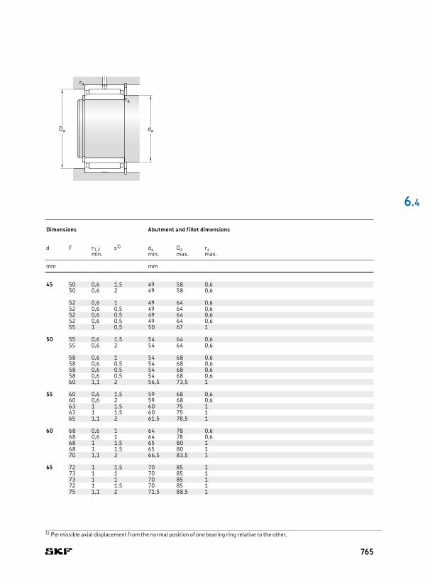
45 62 25 – 42,9 91,5 11,2 8 000 9 000 0,22 NKI 45/25 TN 45 50 0,6 1,5 49 58 0,662 35 – 58,3 137 17 8 000 9 000 0,31 NKI 45/35 TN 50 0,6 2 49 58 0,6
68 22 – 45,7 78 9,65 7 500 8 500 0,27 NA 4909 52 0,6 1 49 64 0,668 22 22 39,1 64 7,8 – 3 800 0,27 NA 4909 RS 52 0,6 0,5 49 64 0,668 23 22 39,1 64 7,8 – 3 800 0,29 NA 4909.2RS 52 0,6 0,5 49 64 0,668 40 – 70,4 137 17 7 500 8 500 0,5 NA 6909 52 0,6 0,5 49 64 0,672 22 – 44,6 78 9,8 7 000 8 000 0,34 NKIS 45 55 1 0,5 50 67 1
50 68 25 – 40,2 88 10,8 7 500 8 500 0,26 NKI 50/25 50 55 0,6 1,5 54 64 0,668 35 – 52,3 122 15,3 7 500 8 500 0,36 NKI 50/35 55 0,6 2 54 64 0,6
72 22 – 47,3 85 10,6 7 000 8 000 0,27 NA 4910 58 0,6 1 54 68 0,672 23 22 40,2 69,5 8,5 – 3 400 0,3 NA 4910 RS 58 0,6 0,5 54 68 0,672 23 22 40,2 69,5 8,5 – 3 400 0,3 NA 4910.2RS 58 0,6 0,5 54 68 0,672 40 – 73,7 150 18,6 7 000 8 000 0,52 NA 6910 58 0,6 0,5 54 68 0,680 28 – 62,7 104 13,2 6 300 7 500 0,52 NKIS 50 60 1,1 2 56,5 73,5 1
55 72 25 – 46,8 110 13,4 6 700 7 500 0,26 NKI 55/25 TN 55 60 0,6 1,5 59 68 0,672 35 – 55 134 17 6 700 7 500 0,36 NKI 55/35 60 0,6 2 59 68 0,680 25 – 57,2 106 13,2 6 300 7 000 0,39 NA 4911 63 1 1,5 60 75 180 45 – 89,7 190 23,2 6 300 7 000 0,78 NA 6911 63 1 1,5 60 75 185 28 – 66 114 14,6 6 000 6 700 0,56 NKIS 55 65 1,1 2 61,5 78,5 1
60 82 25 – 44 95 11,8 6 000 6 700 0,39 NKI 60/25 60 68 0,6 1 64 78 0,682 35 – 60,5 146 18,3 6 000 6 700 0,55 NKI 60/35 68 0,6 1 64 78 0,685 25 – 60,5 114 14,3 6 000 6 700 0,43 NA 4912 68 1 1,5 65 80 185 45 – 93,5 204 25 6 000 6 700 0,81 NA 6912 68 1 1,5 65 80 190 28 – 68,2 120 15,3 5 600 6 300 0,56 NKIS 60 70 1,1 2 66,5 83,5 1
65 90 25 – 61,6 120 14,6 5 600 6 300 0,46 NA 4913 65 72 1 1,5 70 85 190 25 – 52,8 106 13,2 5 600 6 300 0,46 NKI 65/25 73 1 1 70 85 190 35 – 73,7 163 20,4 5 600 6 300 0,66 NKI 65/35 73 1 1 70 85 190 45 – 95,2 212 26 5 600 6 300 0,83 NA 6913 72 1 1,5 70 85 195 28 – 70,4 132 16,6 5 300 6 000 0,64 NKIS 65 75 1,1 2 71,5 88,5 1
6 .4
1) Permissible axial displacement from the normal position of one bearing ring relative to the other.
Principal dimensions Basic load ratings Fatigue
load limitSpeed ratings Mass Designation Dimensions Abutment and fillet dimensions
dynamic static Reference speed
Limiting speed
d D B C C C0 Pu d F r1,2 s1) da Da ramin. min. max. max.
mm kN kN r/min kg – mm mm
daDa
ra
ra
765

70 95 25 56,1 127 15,6 5 000 5 600 0,51 NKI 70/25 70 80 1 0,8 75 90 195 35 76,5 190 24 5 000 5 600 0,72 NKI 70/35 80 1 0,8 75 90 1100 30 84,2 163 20,8 5 000 5 600 0,73 NA 4914 80 1 1,5 75 95 1100 54 128 285 36 5 000 5 600 1,35 NA 6914 80 1 1 75 95 1
75 105 25 69,3 132 16,6 4 800 5 300 0,64 NKI 75/25 75 85 1 1 80 100 1105 30 84,2 170 21,6 4 800 5 300 0,78 NA 4915 85 1 1,5 80 100 1105 35 96,8 200 26 4 800 5 300 0,91 NKI 75/35 85 1 1 80 100 1105 54 130 290 37,5 4 800 5 300 1,45 NA 6915 85 1 1 80 100 1
80 110 25 72,1 140 18 4 500 5 000 0,68 NKI 80/25 80 90 1 1 85 105 1110 30 88 183 23,2 4 500 5 000 0,88 NA 4916 90 1 1,5 85 105 1110 35 101 216 28 4 500 5 000 0,96 NKI 80/35 90 1 1 85 105 1110 54 134 315 40 4 500 5 000 1,5 NA 6916 90 1 1 85 105 1
85 115 26 73,7 146 18,6 4 300 4 800 0,74 NKI 85/26 85 95 1 1,5 90 110 1115 36 105 232 30 4 300 4 800 1,05 NKI 85/36 95 1 1,5 90 110 1120 35 108 250 31 4 000 4 500 1,25 NA 4917 100 1,1 1 91,5 113,5 1120 63 165 425 53 4 000 4 500 2,2 NA 6917 100 1,1 1 91,5 113,5 1
90 120 26 76,5 156 19,6 4 000 4 500 0,78 NKI 90/26 90 100 1 1,5 95 115 1120 36 108 250 31 4 000 4 500 1,1 NKI 90/36 100 1 1,5 95 115 1125 35 112 265 32,5 3 800 4 300 1,3 NA 4918 105 1,1 1 96,5 118,5 1125 63 172 450 55 3 800 4 300 2,3 NA 6918 105 1,1 1 96,5 118,5 1
95 125 26 78,1 166 20,4 3 800 4 300 0,82 NKI 95/26 95 105 1 1,5 100 120 1125 36 112 265 32,5 3 800 4 300 1,15 NKI 95/36 105 1 1,5 100 120 1130 35 114 270 33,5 3 600 4 000 1,35 NA 4919 110 1,1 1 101,5 123,5 1130 63 172 465 56 3 600 4 000 2,5 NA 6919 110 1,1 1 101,5 123,5 1
100 130 30 96,8 220 27 3 600 4 000 0,99 NKI 100/30 100 110 1,1 1,5 106,5 123,5 1130 40 123 305 37,5 3 600 4 000 1,35 NKI 100/40 110 1,1 2 106,5 123,5 1140 40 125 280 34 3 400 4 000 1,9 NA 4920 115 1,1 2 106,5 133,5 1
110 140 30 93,5 232 27 3 400 3 800 1,1 NA 4822 110 120 1 0,8 115 135 1150 40 130 300 35,5 3 200 3 600 2,05 NA 4922 125 1,1 2 116,5 143,5 1
6.4 Needle roller bearings with machined rings with flanges, with an inner ringd 70 – 110 mm
Principal dimensions Basic load ratings Fatigue
load limitSpeed ratings Mass Designation Dimensions Abutment and fillet dimensions
dynamic static Reference speed
Limiting speed
d D B C C0 Pu d F r1,2 s1) da Da ramin. min. max. max.
mm kN kN r/min kg – mm mm
d
B
r1
F
r1
r2
r2
D
NKI(S) NA 69NA 48NA 49
766
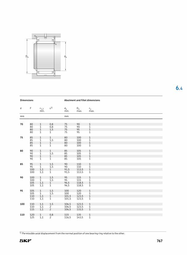
70 95 25 56,1 127 15,6 5 000 5 600 0,51 NKI 70/25 70 80 1 0,8 75 90 195 35 76,5 190 24 5 000 5 600 0,72 NKI 70/35 80 1 0,8 75 90 1100 30 84,2 163 20,8 5 000 5 600 0,73 NA 4914 80 1 1,5 75 95 1100 54 128 285 36 5 000 5 600 1,35 NA 6914 80 1 1 75 95 1
75 105 25 69,3 132 16,6 4 800 5 300 0,64 NKI 75/25 75 85 1 1 80 100 1105 30 84,2 170 21,6 4 800 5 300 0,78 NA 4915 85 1 1,5 80 100 1105 35 96,8 200 26 4 800 5 300 0,91 NKI 75/35 85 1 1 80 100 1105 54 130 290 37,5 4 800 5 300 1,45 NA 6915 85 1 1 80 100 1
80 110 25 72,1 140 18 4 500 5 000 0,68 NKI 80/25 80 90 1 1 85 105 1110 30 88 183 23,2 4 500 5 000 0,88 NA 4916 90 1 1,5 85 105 1110 35 101 216 28 4 500 5 000 0,96 NKI 80/35 90 1 1 85 105 1110 54 134 315 40 4 500 5 000 1,5 NA 6916 90 1 1 85 105 1
85 115 26 73,7 146 18,6 4 300 4 800 0,74 NKI 85/26 85 95 1 1,5 90 110 1115 36 105 232 30 4 300 4 800 1,05 NKI 85/36 95 1 1,5 90 110 1120 35 108 250 31 4 000 4 500 1,25 NA 4917 100 1,1 1 91,5 113,5 1120 63 165 425 53 4 000 4 500 2,2 NA 6917 100 1,1 1 91,5 113,5 1
90 120 26 76,5 156 19,6 4 000 4 500 0,78 NKI 90/26 90 100 1 1,5 95 115 1120 36 108 250 31 4 000 4 500 1,1 NKI 90/36 100 1 1,5 95 115 1125 35 112 265 32,5 3 800 4 300 1,3 NA 4918 105 1,1 1 96,5 118,5 1125 63 172 450 55 3 800 4 300 2,3 NA 6918 105 1,1 1 96,5 118,5 1
95 125 26 78,1 166 20,4 3 800 4 300 0,82 NKI 95/26 95 105 1 1,5 100 120 1125 36 112 265 32,5 3 800 4 300 1,15 NKI 95/36 105 1 1,5 100 120 1130 35 114 270 33,5 3 600 4 000 1,35 NA 4919 110 1,1 1 101,5 123,5 1130 63 172 465 56 3 600 4 000 2,5 NA 6919 110 1,1 1 101,5 123,5 1
100 130 30 96,8 220 27 3 600 4 000 0,99 NKI 100/30 100 110 1,1 1,5 106,5 123,5 1130 40 123 305 37,5 3 600 4 000 1,35 NKI 100/40 110 1,1 2 106,5 123,5 1140 40 125 280 34 3 400 4 000 1,9 NA 4920 115 1,1 2 106,5 133,5 1
110 140 30 93,5 232 27 3 400 3 800 1,1 NA 4822 110 120 1 0,8 115 135 1150 40 130 300 35,5 3 200 3 600 2,05 NA 4922 125 1,1 2 116,5 143,5 1
6 .4
1) Permissible axial displacement from the normal position of one bearing ring relative to the other.
Principal dimensions Basic load ratings Fatigue
load limitSpeed ratings Mass Designation Dimensions Abutment and fillet dimensions
dynamic static Reference speed
Limiting speed
d D B C C0 Pu d F r1,2 s1) da Da ramin. min. max. max.
mm kN kN r/min kg – mm mm
daDa
ra
ra
767
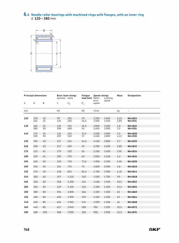
120 150 30 99 255 29 3 200 3 600 1,15 NA 4824 120 130 1 0,8 125 145 1165 45 176 405 46,5 3 000 3 400 2,85 NA 4924 135 1,1 2 126,5 158,5 1
130 165 35 119 325 36,5 2 800 3 200 1,8 NA 4826 130 145 1,1 1 136,5 158,5 1180 50 198 480 54 2 600 3 000 3,9 NA 4926 150 1,5 1,5 138 172 1,5
140 175 35 121 345 37,5 2 600 3 000 1,9 NA 4828 140 155 1,1 1 146,5 168,5 1190 50 205 510 57 2 400 2 800 4,15 NA 4928 160 1,5 1,5 148 182 1,5
150 190 40 147 415 46,5 2 400 2 800 2,7 NA 4830 150 165 1,1 1,5 156,5 183,5 1
160 200 40 157 450 49 2 200 2 600 2,85 NA 4832 160 175 1,1 1,5 166,5 193,5 1
170 215 45 179 520 56 2 200 2 400 3,95 NA 4834 170 185 1,1 1,5 176,5 208,5 1
180 225 45 190 570 60 2 000 2 400 4,2 NA 4836 180 195 1,1 1,5 186,5 218,5 1
190 240 50 220 710 73,5 1 900 2 200 5,55 NA 4838 190 210 1,5 1,5 198 232 1,5
200 250 50 224 735 75 1 800 2 000 5,8 NA 4840 200 220 1,5 1,5 208 242 1,5
220 270 50 238 815 81,5 1 700 1 900 6,35 NA 4844 220 240 1,5 1,5 228 262 1,5
240 300 60 347 1 120 110 1 500 1 700 9,9 NA 4848 240 265 2 2 249 291 2
260 320 60 358 1 200 114 1 400 1 500 10,5 NA 4852 260 285 2 2 269 311 2
280 350 69 429 1 320 125 1 300 1 400 15,5 NA 4856 280 305 2 2,5 289 341 2
300 380 80 594 1 800 166 1 100 1 300 22 NA 4860 300 330 2,1 2 311 369 2
320 400 80 605 1 900 170 1 100 1 200 23 NA 4864 320 350 2,1 2 331 389 2
340 420 80 616 1 960 176 1 000 1 200 24 NA 4868 340 370 2,1 2 351 409 2
360 440 80 627 2 040 180 950 1 100 25,5 NA 4872 360 390 2,1 2 371 429 2
380 480 100 968 3 000 260 900 1 000 42,5 NA 4876 380 415 2,1 2 391 469 2
6.4 Needle roller bearings with machined rings with flanges, with an inner ringd 120 – 380 mm
Principal dimensions Basic load ratings Fatigue
load limitSpeed ratings Mass Designation Dimensions Abutment and fillet dimensions
dynamic static Reference speed
Limiting speed
d D B C C0 Pu d F r1,2 s1) da Da ramin. min. max. max.
mm kN kN r/min kg – mm mm
d
B
r1
F
r1
r2
r2
D
768
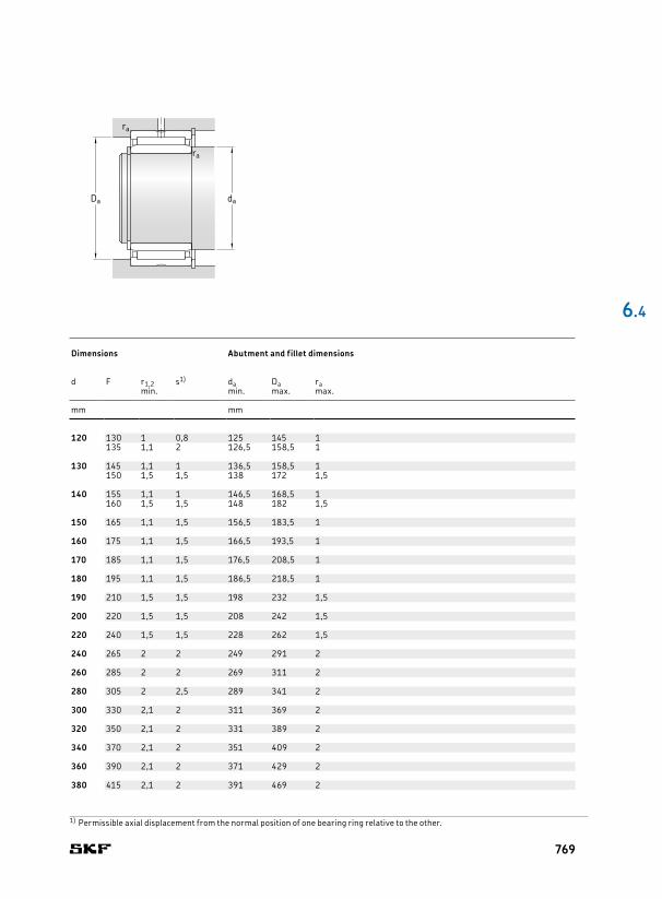
120 150 30 99 255 29 3 200 3 600 1,15 NA 4824 120 130 1 0,8 125 145 1165 45 176 405 46,5 3 000 3 400 2,85 NA 4924 135 1,1 2 126,5 158,5 1
130 165 35 119 325 36,5 2 800 3 200 1,8 NA 4826 130 145 1,1 1 136,5 158,5 1180 50 198 480 54 2 600 3 000 3,9 NA 4926 150 1,5 1,5 138 172 1,5
140 175 35 121 345 37,5 2 600 3 000 1,9 NA 4828 140 155 1,1 1 146,5 168,5 1190 50 205 510 57 2 400 2 800 4,15 NA 4928 160 1,5 1,5 148 182 1,5
150 190 40 147 415 46,5 2 400 2 800 2,7 NA 4830 150 165 1,1 1,5 156,5 183,5 1
160 200 40 157 450 49 2 200 2 600 2,85 NA 4832 160 175 1,1 1,5 166,5 193,5 1
170 215 45 179 520 56 2 200 2 400 3,95 NA 4834 170 185 1,1 1,5 176,5 208,5 1
180 225 45 190 570 60 2 000 2 400 4,2 NA 4836 180 195 1,1 1,5 186,5 218,5 1
190 240 50 220 710 73,5 1 900 2 200 5,55 NA 4838 190 210 1,5 1,5 198 232 1,5
200 250 50 224 735 75 1 800 2 000 5,8 NA 4840 200 220 1,5 1,5 208 242 1,5
220 270 50 238 815 81,5 1 700 1 900 6,35 NA 4844 220 240 1,5 1,5 228 262 1,5
240 300 60 347 1 120 110 1 500 1 700 9,9 NA 4848 240 265 2 2 249 291 2
260 320 60 358 1 200 114 1 400 1 500 10,5 NA 4852 260 285 2 2 269 311 2
280 350 69 429 1 320 125 1 300 1 400 15,5 NA 4856 280 305 2 2,5 289 341 2
300 380 80 594 1 800 166 1 100 1 300 22 NA 4860 300 330 2,1 2 311 369 2
320 400 80 605 1 900 170 1 100 1 200 23 NA 4864 320 350 2,1 2 331 389 2
340 420 80 616 1 960 176 1 000 1 200 24 NA 4868 340 370 2,1 2 351 409 2
360 440 80 627 2 040 180 950 1 100 25,5 NA 4872 360 390 2,1 2 371 429 2
380 480 100 968 3 000 260 900 1 000 42,5 NA 4876 380 415 2,1 2 391 469 2
6 .4
1) Permissible axial displacement from the normal position of one bearing ring relative to the other.
Principal dimensions Basic load ratings Fatigue
load limitSpeed ratings Mass Designation Dimensions Abutment and fillet dimensions
dynamic static Reference speed
Limiting speed
d D B C C0 Pu d F r1,2 s1) da Da ramin. min. max. max.
mm kN kN r/min kg – mm mm
daDa
ra
ra
769

5 10 8 2,29 2 0,212 36 000 40 000 0,003 RNAO 5x10x8 TN 5 8 0,15 7,7 8,3 5,3 0,1
6 13 8 2,55 2,36 0,25 34 000 38 000 0,006 RNAO 6x13x8 TN 6 9 0,3 8,7 9,3 6,3 0,3
7 14 8 2,81 2,75 0,29 32 000 36 000 0,006 RNAO 7x14x8 TN 7 10 0,3 9,7 10,3 7,3 0,3
8 15 10 3,8 4,25 0,465 32 000 36 000 0,008 RNAO 8x15x10 TN 8 11 0,3 10,7 11,3 8,3 0,3
10 17 10 4,57 5,7 0,63 28 000 32 000 0,01 RNAO 10x17x10 TN 10 13 0,3 12,7 13,3 10,3 0,3
12 22 12 9,52 10 1,18 26 000 30 000 0,019 RNAO 12x22x12 TN 12 18 0,3 17,6 18,3 12,3 0,3
15 23 13 8,25 11,2 1,29 24 000 28 000 0,02 RNAO 15x23x13 15 19 0,3 18,6 19,3 15,4 0,3
16 24 13 8,58 12 1,37 24 000 26 000 0,021 RNAO 16x24x13 16 20 0,3 19,6 20,3 16,4 0,328 12 11 12,5 1,5 22 000 26 000 0,032 RNAO 16x28x12 22 0,3 21,6 22,3 16,4 0,3
17 25 13 10,1 14,6 1,73 22 000 26 000 0,022 RNAO 17x25x13 17 21 0,3 20,6 21,3 17,4 0,3
18 30 24 20,9 30 3,6 20 000 24 000 0,069 RNAO 18x30x241) 18 24 0,3 23,6 24,5 18,4 0,3
20 28 13 9,52 14,6 1,66 20 000 22 000 0,025 RNAO 20x28x13 20 24 0,3 23,6 24,3 20,4 0,328 26 16,1 29 3,35 20 000 22 000 0,05 RNAO 20x28x261) 24 0,3 23,6 24,3 20,4 0,332 12 12,8 16,3 1,96 19 000 22 000 0,038 RNAO 20x32x12 26 0,3 25,6 26,5 20,4 0,3
22 30 13 10,1 16,3 1,86 18 000 20 000 0,027 RNAO 22x30x13 22 26 0,3 25,6 26,3 22,4 0,335 16 19,4 25,5 3,05 17 000 19 000 0,059 RNAO 22x35x16 29 0,3 28,4 29,5 22,4 0,3
25 35 17 14,2 26,5 3,1 16 000 18 000 0,053 RNAO 25x35x17 25 29 0,3 28,4 29,5 25,6 0,335 26 18,7 37,5 4,3 16 000 18 000 0,076 RNAO 25x35x261) 29 0,3 28,4 29,5 25,6 0,337 16 20,1 28 3,35 15 000 17 000 0,06 RNAO 25x37x16 32 0,3 31,4 32,5 25,6 0,3
30 40 17 18,7 34 4,05 13 000 15 000 0,06 RNAO 30x40x17 30 35 0,3 34,4 35,5 30,6 0,342 16 22 33,5 4 13 000 15 000 0,059 RNAO 30x42x16 37 0,3 36,4 37,5 30,6 0,342 32 38 67 8 13 000 15 000 0,14 RNAO 30x42x321) 37 0,3 36,4 37,5 30,6 0,3
6.5 Needle roller bearings with machined rings without flanges, without an inner ringFw 5 – 30 mm
1) Double row, outer ring with a lubrication hole and an annular groove.
Principal dimensions Basic load ratings Fatigue
load limitSpeed ratings Mass Designation Dimensions Abutment and fillet dimensions
dynamic static Reference speed
Limiting speed
Fw D C C C0 Pu Fw E r1,2 da Da Db ramin. max.
mm kN kN r/min kg – mm mm
CC
Fw
r1
r2
ED
RNAO RNAO(double row)
770

5 10 8 2,29 2 0,212 36 000 40 000 0,003 RNAO 5x10x8 TN 5 8 0,15 7,7 8,3 5,3 0,1
6 13 8 2,55 2,36 0,25 34 000 38 000 0,006 RNAO 6x13x8 TN 6 9 0,3 8,7 9,3 6,3 0,3
7 14 8 2,81 2,75 0,29 32 000 36 000 0,006 RNAO 7x14x8 TN 7 10 0,3 9,7 10,3 7,3 0,3
8 15 10 3,8 4,25 0,465 32 000 36 000 0,008 RNAO 8x15x10 TN 8 11 0,3 10,7 11,3 8,3 0,3
10 17 10 4,57 5,7 0,63 28 000 32 000 0,01 RNAO 10x17x10 TN 10 13 0,3 12,7 13,3 10,3 0,3
12 22 12 9,52 10 1,18 26 000 30 000 0,019 RNAO 12x22x12 TN 12 18 0,3 17,6 18,3 12,3 0,3
15 23 13 8,25 11,2 1,29 24 000 28 000 0,02 RNAO 15x23x13 15 19 0,3 18,6 19,3 15,4 0,3
16 24 13 8,58 12 1,37 24 000 26 000 0,021 RNAO 16x24x13 16 20 0,3 19,6 20,3 16,4 0,328 12 11 12,5 1,5 22 000 26 000 0,032 RNAO 16x28x12 22 0,3 21,6 22,3 16,4 0,3
17 25 13 10,1 14,6 1,73 22 000 26 000 0,022 RNAO 17x25x13 17 21 0,3 20,6 21,3 17,4 0,3
18 30 24 20,9 30 3,6 20 000 24 000 0,069 RNAO 18x30x241) 18 24 0,3 23,6 24,5 18,4 0,3
20 28 13 9,52 14,6 1,66 20 000 22 000 0,025 RNAO 20x28x13 20 24 0,3 23,6 24,3 20,4 0,328 26 16,1 29 3,35 20 000 22 000 0,05 RNAO 20x28x261) 24 0,3 23,6 24,3 20,4 0,332 12 12,8 16,3 1,96 19 000 22 000 0,038 RNAO 20x32x12 26 0,3 25,6 26,5 20,4 0,3
22 30 13 10,1 16,3 1,86 18 000 20 000 0,027 RNAO 22x30x13 22 26 0,3 25,6 26,3 22,4 0,335 16 19,4 25,5 3,05 17 000 19 000 0,059 RNAO 22x35x16 29 0,3 28,4 29,5 22,4 0,3
25 35 17 14,2 26,5 3,1 16 000 18 000 0,053 RNAO 25x35x17 25 29 0,3 28,4 29,5 25,6 0,335 26 18,7 37,5 4,3 16 000 18 000 0,076 RNAO 25x35x261) 29 0,3 28,4 29,5 25,6 0,337 16 20,1 28 3,35 15 000 17 000 0,06 RNAO 25x37x16 32 0,3 31,4 32,5 25,6 0,3
30 40 17 18,7 34 4,05 13 000 15 000 0,06 RNAO 30x40x17 30 35 0,3 34,4 35,5 30,6 0,342 16 22 33,5 4 13 000 15 000 0,059 RNAO 30x42x16 37 0,3 36,4 37,5 30,6 0,342 32 38 67 8 13 000 15 000 0,14 RNAO 30x42x321) 37 0,3 36,4 37,5 30,6 0,3
6 .5
Db
ra
daDa
ra
Principal dimensions Basic load ratings Fatigue
load limitSpeed ratings Mass Designation Dimensions Abutment and fillet dimensions
dynamic static Reference speed
Limiting speed
Fw D C C C0 Pu Fw E r1,2 da Da Db ramin. max.
mm kN kN r/min kg – mm mm
771

35 45 13 15,4 28 3,25 12 000 13 000 0,059 RNAO 35x45x13 35 40 0,3 39,4 40,5 35,6 0,345 17 19,8 39 4,65 12 000 13 000 0,069 RNAO 35x45x17 40 0,3 39,4 40,5 35,6 0,345 26 26,4 56 6,55 12 000 13 000 0,091 RNAO 35x45x261) 40 0,3 39,4 40,5 35,6 0,347 16 23,3 37,5 4,5 11 000 13 000 0,078 RNAO 35x47x16 42 0,3 41,4 42,5 35,6 0,347 18 26,4 44 5,3 11 000 13 000 0,076 RNAO 35x47x18 42 0,3 41,4 42,5 35,6 0,347 32 40,2 75 9 11 000 13 000 0,16 RNAO 35x47x321) 42 0,3 41,4 42,5 35,6 0,3
40 50 17 20,5 41,5 5 10 000 12 000 0,074 RNAO 40x50x17 40 45 0,3 44,4 45,5 40,6 0,350 34 35,2 83 10 10 000 12 000 0,15 RNAO 40x50x341) 45 0,3 44,4 45,5 40,6 0,355 20 31,4 57 6,95 10 000 11 000 0,15 RNAO 40x55x20 47 0,3 46,2 47,5 40,6 0,355 40 59,4 118 14,6 10 000 11 000 0,28 RNAO 40x55x401) 48 0,3 47,2 47,5 40,6 0,3
45 55 17 21,6 46,5 5,6 9 000 10 000 0,083 RNAO 45x55x17 45 50 0,3 49,2 50,5 45,6 0,362 40 64,4 137 16,6 9 000 10 000 0,38 RNAO 45x62x401) 53 0,3 52,2 53,5 45,6 0,3
50 62 20 25,5 60 7,2 8 500 9 500 0,14 RNAO 50x62x20 50 55 0,3 54,2 55,8 50,6 0,365 20 34,1 62 7,65 8 000 9 000 0,17 RNAO 50x65x20 58 0,3 57,2 58,5 50,6 0,365 40 58,3 125 15,3 8 000 9 000 0,36 RNAO 50x65x401) 58 0,6 57,2 58,5 50,6 0,6
55 68 20 27 67 8,15 7 500 8 500 0,17 RNAO 55x68x20 55 60 0,6 59,2 60,8 55,8 0,6
60 78 20 41,8 86,5 10,6 6 700 7 500 0,26 RNAO 60x78x20 60 68 1 67,2 68,8 60,8 178 40 72,1 173 21,2 6 700 7 500 0,44 RNAO 60x78x401) 68 1 67,2 68,8 60,8 1
65 85 30 53,9 125 15,6 6 300 7 000 0,46 RNAO 65x85x30 65 73 1 72,2 73,8 66 1
70 90 30 57,2 137 17 6 000 6 700 0,5 RNAO 70x90x30 70 78 1 77,2 78,8 71 1
80 100 30 68,2 176 22 5 000 6 000 0,58 RNAO 80x100x30 80 88 1 87,2 89 81 1
90 105 26 58,3 150 18,6 4 500 5 300 0,37 RNAO 90x105x26 90 98 1 97,2 99 91 1110 30 64,4 173 21,6 4 500 5 300 0,61 RNAO 90x110x30 98 1 97,2 99 91 1
100 120 30 67,1 190 23,6 4 000 4 800 0,69 RNAO 100x120x30 100 108 1 107,2 109 101 1
6.5 Needle roller bearings with machined rings without flanges, without an inner ringFw 35 – 100 mm
1) Double row, outer ring with a lubrication hole and an annular groove.
Principal dimensions Basic load ratings Fatigue
load limitSpeed ratings Mass Designation Dimensions Abutment and fillet dimensions
dynamic static Reference speed
Limiting speed
Fw D C C C0 Pu Fw E r1,2 da Da Db ramin. max.
mm kN kN r/min kg – mm mm
CC
Fw
r1
r2
ED
RNAO RNAO(double row)
772

35 45 13 15,4 28 3,25 12 000 13 000 0,059 RNAO 35x45x13 35 40 0,3 39,4 40,5 35,6 0,345 17 19,8 39 4,65 12 000 13 000 0,069 RNAO 35x45x17 40 0,3 39,4 40,5 35,6 0,345 26 26,4 56 6,55 12 000 13 000 0,091 RNAO 35x45x261) 40 0,3 39,4 40,5 35,6 0,347 16 23,3 37,5 4,5 11 000 13 000 0,078 RNAO 35x47x16 42 0,3 41,4 42,5 35,6 0,347 18 26,4 44 5,3 11 000 13 000 0,076 RNAO 35x47x18 42 0,3 41,4 42,5 35,6 0,347 32 40,2 75 9 11 000 13 000 0,16 RNAO 35x47x321) 42 0,3 41,4 42,5 35,6 0,3
40 50 17 20,5 41,5 5 10 000 12 000 0,074 RNAO 40x50x17 40 45 0,3 44,4 45,5 40,6 0,350 34 35,2 83 10 10 000 12 000 0,15 RNAO 40x50x341) 45 0,3 44,4 45,5 40,6 0,355 20 31,4 57 6,95 10 000 11 000 0,15 RNAO 40x55x20 47 0,3 46,2 47,5 40,6 0,355 40 59,4 118 14,6 10 000 11 000 0,28 RNAO 40x55x401) 48 0,3 47,2 47,5 40,6 0,3
45 55 17 21,6 46,5 5,6 9 000 10 000 0,083 RNAO 45x55x17 45 50 0,3 49,2 50,5 45,6 0,362 40 64,4 137 16,6 9 000 10 000 0,38 RNAO 45x62x401) 53 0,3 52,2 53,5 45,6 0,3
50 62 20 25,5 60 7,2 8 500 9 500 0,14 RNAO 50x62x20 50 55 0,3 54,2 55,8 50,6 0,365 20 34,1 62 7,65 8 000 9 000 0,17 RNAO 50x65x20 58 0,3 57,2 58,5 50,6 0,365 40 58,3 125 15,3 8 000 9 000 0,36 RNAO 50x65x401) 58 0,6 57,2 58,5 50,6 0,6
55 68 20 27 67 8,15 7 500 8 500 0,17 RNAO 55x68x20 55 60 0,6 59,2 60,8 55,8 0,6
60 78 20 41,8 86,5 10,6 6 700 7 500 0,26 RNAO 60x78x20 60 68 1 67,2 68,8 60,8 178 40 72,1 173 21,2 6 700 7 500 0,44 RNAO 60x78x401) 68 1 67,2 68,8 60,8 1
65 85 30 53,9 125 15,6 6 300 7 000 0,46 RNAO 65x85x30 65 73 1 72,2 73,8 66 1
70 90 30 57,2 137 17 6 000 6 700 0,5 RNAO 70x90x30 70 78 1 77,2 78,8 71 1
80 100 30 68,2 176 22 5 000 6 000 0,58 RNAO 80x100x30 80 88 1 87,2 89 81 1
90 105 26 58,3 150 18,6 4 500 5 300 0,37 RNAO 90x105x26 90 98 1 97,2 99 91 1110 30 64,4 173 21,6 4 500 5 300 0,61 RNAO 90x110x30 98 1 97,2 99 91 1
100 120 30 67,1 190 23,6 4 000 4 800 0,69 RNAO 100x120x30 100 108 1 107,2 109 101 1
6 .5
Principal dimensions Basic load ratings Fatigue
load limitSpeed ratings Mass Designation Dimensions Abutment and fillet dimensions
dynamic static Reference speed
Limiting speed
Fw D C C C0 Pu Fw E r1,2 da Da Db ramin. max.
mm kN kN r/min kg – mm mm
Db
ra
daDa
ra
773
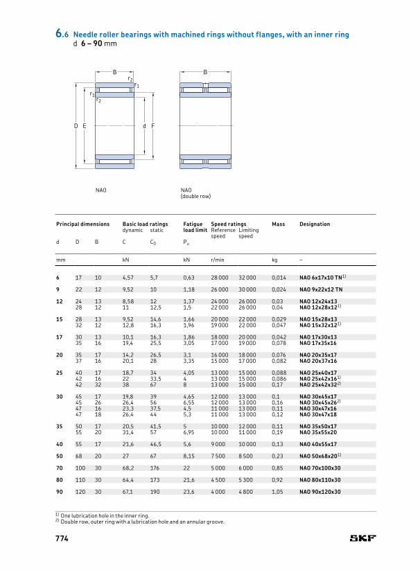
6 17 10 4,57 5,7 0,63 28 000 32 000 0,014 NAO 6x17x10 TN1) 6 13 10 0,3 0,5 12,7 9,7 13,3 10,3 0,3
9 22 12 9,52 10 1,18 26 000 30 000 0,024 NAO 9x22x12 TN 9 18 12 0,3 0,5 17,6 11,7 18,3 12,3 0,3
12 24 13 8,58 12 1,37 24 000 26 000 0,03 NAO 12x24x13 12 20 16 0,3 0,5 19,6 15,7 20,3 16,4 0,328 12 11 12,5 1,5 22 000 26 000 0,04 NAO 12x28x121) 22 16 0,3 0,5 21,6 15,7 22,3 16,4 0,3
15 28 13 9,52 14,6 1,66 20 000 22 000 0,029 NAO 15x28x13 15 24 20 0,3 0,5 23,6 19,7 24,3 20,4 0,332 12 12,8 16,3 1,96 19 000 22 000 0,047 NAO 15x32x121) 26 20 0,3 0,5 25,6 19,7 26,5 20,4 0,3
17 30 13 10,1 16,3 1,86 18 000 20 000 0,042 NAO 17x30x13 17 26 22 0,3 0,5 25,6 21,5 26,3 22,4 0,335 16 19,4 25,5 3,05 17 000 19 000 0,078 NAO 17x35x16 29 22 0,3 0,5 28,4 21,5 29,5 22,4 0,3
20 35 17 14,2 26,5 3,1 16 000 18 000 0,076 NAO 20x35x17 20 29 25 0,3 0,5 28,4 24,5 29,5 25,6 0,337 16 20,1 28 3,35 15 000 17 000 0,082 NAO 20x37x16 32 25 0,3 0,5 31,4 24,5 32,5 25,6 0,3
25 40 17 18,7 34 4,05 13 000 15 000 0,088 NAO 25x40x17 25 35 30 0,3 0,8 34,4 29,5 35,5 30,6 0,342 16 22 33,5 4 13 000 15 000 0,086 NAO 25x42x161) 37 30 0,3 0,8 36,4 29,5 37,5 30,6 0,342 32 38 67 8 13 000 15 000 0,17 NAO 25x42x322) 37 30 0,3 0,8 36,4 29,5 37,5 30,6 0,3
30 45 17 19,8 39 4,65 12 000 13 000 0,1 NAO 30x45x17 30 40 35 0,3 0,8 39,4 34,5 40,5 35,6 0,345 26 26,4 56 6,55 12 000 13 000 0,16 NAO 30x45x262) 40 35 0,3 0,8 39,4 34,5 40,5 35,6 0,347 16 23,3 37,5 4,5 11 000 13 000 0,11 NAO 30x47x16 42 35 0,3 0,8 41,4 34,5 42,5 35,6 0,347 18 26,4 44 5,3 11 000 13 000 0,12 NAO 30x47x18 42 35 0,3 0,8 41,4 34,5 42,5 35,6 0,3
35 50 17 20,5 41,5 5 10 000 12 000 0,11 NAO 35x50x17 35 45 40 0,3 0,8 44,4 39,5 45,5 40,6 0,355 20 31,4 57 6,95 10 000 11 000 0,19 NAO 35x55x20 47 40 0,3 0,8 46,2 39,5 47,5 40,6 0,3
40 55 17 21,6 46,5 5,6 9 000 10 000 0,13 NAO 40x55x17 40 50 45 0,3 0,8 49,2 44,5 50,5 45,6 0,3
50 68 20 27 67 8,15 7 500 8 500 0,23 NAO 50x68x201) 50 60 55 0,6 1 59,2 54,5 60,8 55,8 0,6
70 100 30 68,2 176 22 5 000 6 000 0,85 NAO 70x100x30 70 88 80 1 1 87,2 79,3 89 81 1
80 110 30 64,4 173 21,6 4 500 5 300 0,92 NAO 80x110x30 80 98 90 1 1 97,2 89,3 99 91 1
90 120 30 67,1 190 23,6 4 000 4 800 1,05 NAO 90x120x30 90 108 100 1 1 107,2 99,3 109 101 1
BB
d
r1
F
r1
r2
r2
ED
6.6 Needle roller bearings with machined rings without flanges, with an inner ringd 6 – 90 mm
1) One lubrication hole in the inner ring.2) Double row, outer ring with a lubrication hole and an annular groove.
Principal dimensions Basic load ratings Fatigue
load limitSpeed ratings Mass Designation Dimensions Abutment and fillet dimensions
dynamic static Reference speed
Limiting speed
d D B C C0 Pu d E F r1,2 s1) da db Da Db ramin. max.
mm kN kN r/min kg – mm mm
NAO NAO(double row)
774
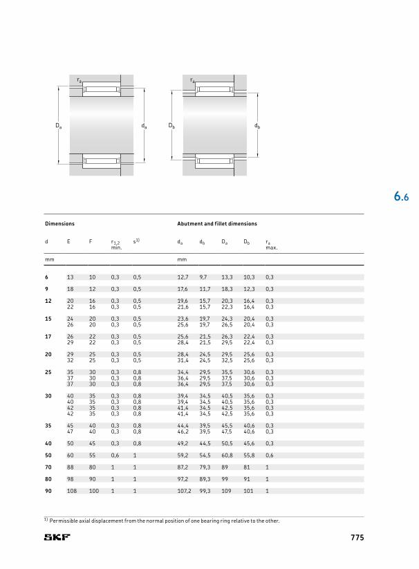
6 17 10 4,57 5,7 0,63 28 000 32 000 0,014 NAO 6x17x10 TN1) 6 13 10 0,3 0,5 12,7 9,7 13,3 10,3 0,3
9 22 12 9,52 10 1,18 26 000 30 000 0,024 NAO 9x22x12 TN 9 18 12 0,3 0,5 17,6 11,7 18,3 12,3 0,3
12 24 13 8,58 12 1,37 24 000 26 000 0,03 NAO 12x24x13 12 20 16 0,3 0,5 19,6 15,7 20,3 16,4 0,328 12 11 12,5 1,5 22 000 26 000 0,04 NAO 12x28x121) 22 16 0,3 0,5 21,6 15,7 22,3 16,4 0,3
15 28 13 9,52 14,6 1,66 20 000 22 000 0,029 NAO 15x28x13 15 24 20 0,3 0,5 23,6 19,7 24,3 20,4 0,332 12 12,8 16,3 1,96 19 000 22 000 0,047 NAO 15x32x121) 26 20 0,3 0,5 25,6 19,7 26,5 20,4 0,3
17 30 13 10,1 16,3 1,86 18 000 20 000 0,042 NAO 17x30x13 17 26 22 0,3 0,5 25,6 21,5 26,3 22,4 0,335 16 19,4 25,5 3,05 17 000 19 000 0,078 NAO 17x35x16 29 22 0,3 0,5 28,4 21,5 29,5 22,4 0,3
20 35 17 14,2 26,5 3,1 16 000 18 000 0,076 NAO 20x35x17 20 29 25 0,3 0,5 28,4 24,5 29,5 25,6 0,337 16 20,1 28 3,35 15 000 17 000 0,082 NAO 20x37x16 32 25 0,3 0,5 31,4 24,5 32,5 25,6 0,3
25 40 17 18,7 34 4,05 13 000 15 000 0,088 NAO 25x40x17 25 35 30 0,3 0,8 34,4 29,5 35,5 30,6 0,342 16 22 33,5 4 13 000 15 000 0,086 NAO 25x42x161) 37 30 0,3 0,8 36,4 29,5 37,5 30,6 0,342 32 38 67 8 13 000 15 000 0,17 NAO 25x42x322) 37 30 0,3 0,8 36,4 29,5 37,5 30,6 0,3
30 45 17 19,8 39 4,65 12 000 13 000 0,1 NAO 30x45x17 30 40 35 0,3 0,8 39,4 34,5 40,5 35,6 0,345 26 26,4 56 6,55 12 000 13 000 0,16 NAO 30x45x262) 40 35 0,3 0,8 39,4 34,5 40,5 35,6 0,347 16 23,3 37,5 4,5 11 000 13 000 0,11 NAO 30x47x16 42 35 0,3 0,8 41,4 34,5 42,5 35,6 0,347 18 26,4 44 5,3 11 000 13 000 0,12 NAO 30x47x18 42 35 0,3 0,8 41,4 34,5 42,5 35,6 0,3
35 50 17 20,5 41,5 5 10 000 12 000 0,11 NAO 35x50x17 35 45 40 0,3 0,8 44,4 39,5 45,5 40,6 0,355 20 31,4 57 6,95 10 000 11 000 0,19 NAO 35x55x20 47 40 0,3 0,8 46,2 39,5 47,5 40,6 0,3
40 55 17 21,6 46,5 5,6 9 000 10 000 0,13 NAO 40x55x17 40 50 45 0,3 0,8 49,2 44,5 50,5 45,6 0,3
50 68 20 27 67 8,15 7 500 8 500 0,23 NAO 50x68x201) 50 60 55 0,6 1 59,2 54,5 60,8 55,8 0,6
70 100 30 68,2 176 22 5 000 6 000 0,85 NAO 70x100x30 70 88 80 1 1 87,2 79,3 89 81 1
80 110 30 64,4 173 21,6 4 500 5 300 0,92 NAO 80x110x30 80 98 90 1 1 97,2 89,3 99 91 1
90 120 30 67,1 190 23,6 4 000 4 800 1,05 NAO 90x120x30 90 108 100 1 1 107,2 99,3 109 101 1
6 .6
dbDb
ra
daDa
ra
1) Permissible axial displacement from the normal position of one bearing ring relative to the other.
Principal dimensions Basic load ratings Fatigue
load limitSpeed ratings Mass Designation Dimensions Abutment and fillet dimensions
dynamic static Reference speed
Limiting speed
d D B C C0 Pu d E F r1,2 s1) da db Da Db ramin. max.
mm kN kN r/min kg – mm mm
775

15 28 12 7,37 9,15 1,08 24 000 28 000 0,032 RPNA 15/28 15 24,5 0,8 23,5 24,5 0,8
18 32 16 12,8 17,6 2,12 22 000 24 000 0,052 RPNA 18/32 18 27 0,8 26 27 0,8
20 35 16 13,2 19,3 2,28 19 000 22 000 0,062 RPNA 20/35 20 30,5 0,8 29,5 30,5 0,8
25 42 20 19 32,5 4 16 000 18 000 0,11 RPNA 25/42 25 36,5 0,8 35 37 0,8
28 44 20 22 36,5 4,55 14 000 16 000 0,11 RPNA 28/44 28 38,5 0,8 37,5 39 0,8
30 47 20 22,9 38 4,8 13 000 15 000 0,13 RPNA 30/47 30 42 0,8 41 42 0,8
35 52 20 24,6 45 5,6 11 000 13 000 0,13 RPNA 35/52 35 47,5 0,8 46,5 47,5 0,8
40 55 20 26,4 51 6,3 10 000 11 000 0,14 RPNA 40/55 40 50,5 0,8 49,5 50,5 0,8
45 62 20 27,5 57 7,1 9 000 10 000 0,18 RPNA 45/62 45 58 0,8 57 58 0,8
C
r
FwD D1
6.7 Alignment needle roller bearings, without an inner ringFw 15 – 45 mm
Principal dimensions Basic load ratings Fatigue
load limitSpeed ratings Mass Designation Dimensions Abutment and fillet dimensions
dynamic static Reference speed
Limiting speed
Fw D C C C0 Pu Fw D1 r Da Da ramin. min. max. max.
mm kN kN r/min kg – mm mm
776
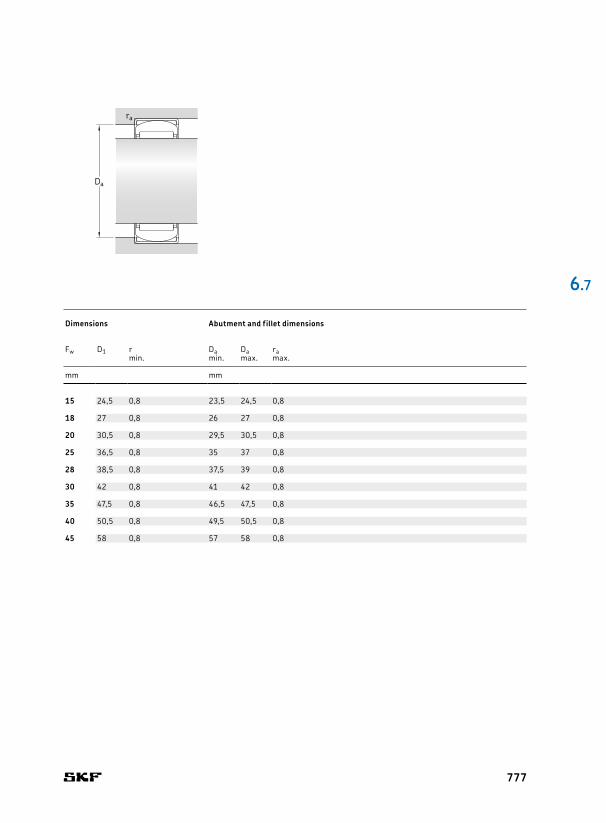
15 28 12 7,37 9,15 1,08 24 000 28 000 0,032 RPNA 15/28 15 24,5 0,8 23,5 24,5 0,8
18 32 16 12,8 17,6 2,12 22 000 24 000 0,052 RPNA 18/32 18 27 0,8 26 27 0,8
20 35 16 13,2 19,3 2,28 19 000 22 000 0,062 RPNA 20/35 20 30,5 0,8 29,5 30,5 0,8
25 42 20 19 32,5 4 16 000 18 000 0,11 RPNA 25/42 25 36,5 0,8 35 37 0,8
28 44 20 22 36,5 4,55 14 000 16 000 0,11 RPNA 28/44 28 38,5 0,8 37,5 39 0,8
30 47 20 22,9 38 4,8 13 000 15 000 0,13 RPNA 30/47 30 42 0,8 41 42 0,8
35 52 20 24,6 45 5,6 11 000 13 000 0,13 RPNA 35/52 35 47,5 0,8 46,5 47,5 0,8
40 55 20 26,4 51 6,3 10 000 11 000 0,14 RPNA 40/55 40 50,5 0,8 49,5 50,5 0,8
45 62 20 27,5 57 7,1 9 000 10 000 0,18 RPNA 45/62 45 58 0,8 57 58 0,8
6 .7
Da
ra
Principal dimensions Basic load ratings Fatigue
load limitSpeed ratings Mass Designation Dimensions Abutment and fillet dimensions
dynamic static Reference speed
Limiting speed
Fw D C C C0 Pu Fw D1 r Da Da ramin. min. max. max.
mm kN kN r/min kg – mm mm
777
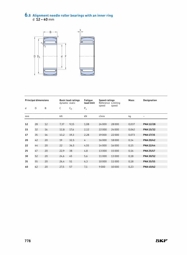
12 28 12 7,37 9,15 1,08 24 000 28 000 0,037 PNA 12/28 12 15 24,5 0,8 0,3 0,5 14 23,5 24,5 0,8 0,3
15 32 16 12,8 17,6 2,12 22 000 24 000 0,062 PNA 15/32 15 18 27 0,8 0,3 0,5 17 26 27 0,8 0,3
17 35 16 13,2 19,3 2,28 19 000 22 000 0,073 PNA 17/35 17 20 30,5 0,8 0,3 0,5 19 29,5 30,5 0,8 0,3
20 42 20 19 32,5 4 16 000 18 000 0,14 PNA 20/42 20 25 36,5 0,8 0,3 0,5 22 35 37 0,8 0,3
22 44 20 22 36,5 4,55 14 000 16 000 0,15 PNA 22/44 22 28 38,5 0,8 0,3 0,5 24 37,5 39 0,8 0,3
25 47 20 22,9 38 4,8 13 000 15 000 0,16 PNA 25/47 25 30 42 0,8 0,3 0,5 25 41 42 0,8 0,3
30 52 20 24,6 45 5,6 11 000 13 000 0,18 PNA 30/52 30 35 47,5 0,8 0,3 0,5 32 46,5 47,5 0,8 0,3
35 55 20 26,4 51 6,3 10 000 11 000 0,18 PNA 35/55 35 40 50,5 0,8 0,3 0,5 37 49,5 50,5 0,8 0,3
40 62 20 27,5 57 7,1 9 000 10 000 0,23 PNA 40/62 40 45 58 0,8 0,3 0,5 42 57 58 0,8 0,3
s
d
B
r
r1
FD1
r2
D
6.8 Alignment needle roller bearings with an inner ringd 12 – 40 mm
Principal dimensions Basic load ratings Fatigue
load limitSpeed ratings Mass Designation Dimensions Abutment and fillet dimensions
dynamic static Reference speed
Limiting speed
d D B C C0 Pu d F D1 r r1,2 s1) da Da Da ra rbmin. min. min. min. max. max. max.
mm kN kN r/min kg – mm mm
778
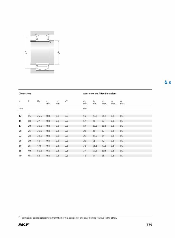
12 28 12 7,37 9,15 1,08 24 000 28 000 0,037 PNA 12/28 12 15 24,5 0,8 0,3 0,5 14 23,5 24,5 0,8 0,3
15 32 16 12,8 17,6 2,12 22 000 24 000 0,062 PNA 15/32 15 18 27 0,8 0,3 0,5 17 26 27 0,8 0,3
17 35 16 13,2 19,3 2,28 19 000 22 000 0,073 PNA 17/35 17 20 30,5 0,8 0,3 0,5 19 29,5 30,5 0,8 0,3
20 42 20 19 32,5 4 16 000 18 000 0,14 PNA 20/42 20 25 36,5 0,8 0,3 0,5 22 35 37 0,8 0,3
22 44 20 22 36,5 4,55 14 000 16 000 0,15 PNA 22/44 22 28 38,5 0,8 0,3 0,5 24 37,5 39 0,8 0,3
25 47 20 22,9 38 4,8 13 000 15 000 0,16 PNA 25/47 25 30 42 0,8 0,3 0,5 25 41 42 0,8 0,3
30 52 20 24,6 45 5,6 11 000 13 000 0,18 PNA 30/52 30 35 47,5 0,8 0,3 0,5 32 46,5 47,5 0,8 0,3
35 55 20 26,4 51 6,3 10 000 11 000 0,18 PNA 35/55 35 40 50,5 0,8 0,3 0,5 37 49,5 50,5 0,8 0,3
40 62 20 27,5 57 7,1 9 000 10 000 0,23 PNA 40/62 40 45 58 0,8 0,3 0,5 42 57 58 0,8 0,3
6 .8
daDa
ra
rb
Principal dimensions Basic load ratings Fatigue
load limitSpeed ratings Mass Designation Dimensions Abutment and fillet dimensions
dynamic static Reference speed
Limiting speed
d D B C C0 Pu d F D1 r r1,2 s1) da Da Da ra rbmin. min. min. min. max. max. max.
mm kN kN r/min kg – mm mm
1) Permissible axial displacement from the normal position of one bearing ring relative to the other.
779
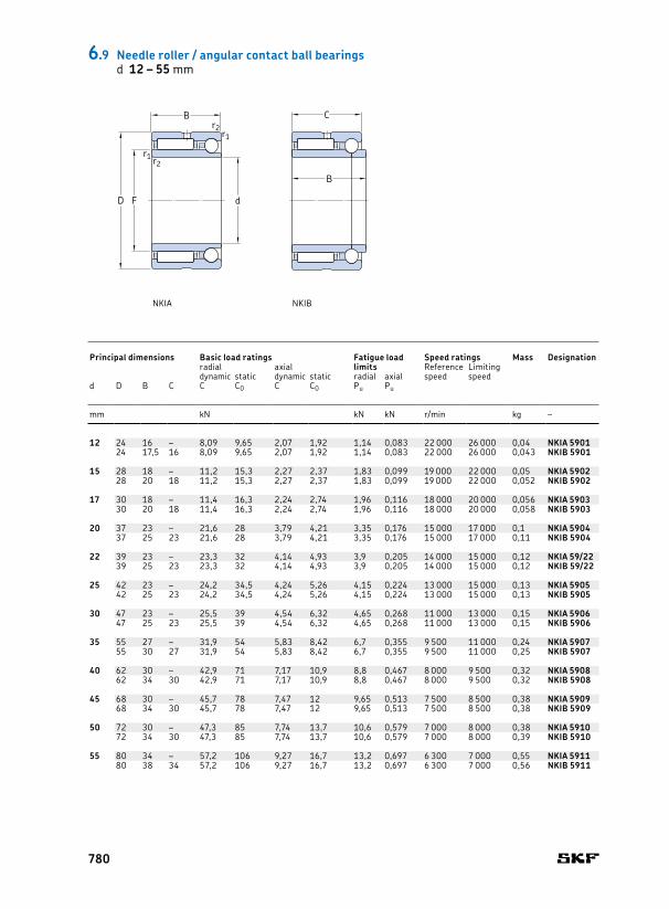
12 24 16 – 8,09 9,65 2,07 1,92 1,14 0,083 22 000 26 000 0,04 NKIA 5901 12 16 0,3 14 22 0,324 17,5 16 8,09 9,65 2,07 1,92 1,14 0,083 22 000 26 000 0,043 NKIB 5901 16 0,3 14 22 0,3
15 28 18 – 11,2 15,3 2,27 2,37 1,83 0,099 19 000 22 000 0,05 NKIA 5902 15 20 0,3 17 26 0,328 20 18 11,2 15,3 2,27 2,37 1,83 0,099 19 000 22 000 0,052 NKIB 5902 20 0,3 17 26 0,3
17 30 18 – 11,4 16,3 2,24 2,74 1,96 0,116 18 000 20 000 0,056 NKIA 5903 17 22 0,3 19 28 0,330 20 18 11,4 16,3 2,24 2,74 1,96 0,116 18 000 20 000 0,058 NKIB 5903 22 0,3 19 28 0,3
20 37 23 – 21,6 28 3,79 4,21 3,35 0,176 15 000 17 000 0,1 NKIA 5904 20 25 0,3 22 35 0,337 25 23 21,6 28 3,79 4,21 3,35 0,176 15 000 17 000 0,11 NKIB 5904 25 0,3 22 35 0,3
22 39 23 – 23,3 32 4,14 4,93 3,9 0,205 14 000 15 000 0,12 NKIA 59/22 22 28 0,3 24 37 0,339 25 23 23,3 32 4,14 4,93 3,9 0,205 14 000 15 000 0,12 NKIB 59/22 28 0,3 24 37 0,3
25 42 23 – 24,2 34,5 4,24 5,26 4,15 0,224 13 000 15 000 0,13 NKIA 5905 25 30 0,3 27 40 0,342 25 23 24,2 34,5 4,24 5,26 4,15 0,224 13 000 15 000 0,13 NKIB 5905 30 0,3 27 40 0,3
30 47 23 – 25,5 39 4,54 6,32 4,65 0,268 11 000 13 000 0,15 NKIA 5906 30 35 0,3 32 45 0,347 25 23 25,5 39 4,54 6,32 4,65 0,268 11 000 13 000 0,15 NKIB 5906 35 0,3 32 45 0,3
35 55 27 – 31,9 54 5,83 8,42 6,7 0,355 9 500 11 000 0,24 NKIA 5907 35 42 0,6 39 51 0,655 30 27 31,9 54 5,83 8,42 6,7 0,355 9 500 11 000 0,25 NKIB 5907 42 0,6 39 51 0,6
40 62 30 – 42,9 71 7,17 10,9 8,8 0,467 8 000 9 500 0,32 NKIA 5908 40 48 0,6 44 58 0,662 34 30 42,9 71 7,17 10,9 8,8 0,467 8 000 9 500 0,32 NKIB 5908 48 0,6 44 58 0,6
45 68 30 – 45,7 78 7,47 12 9,65 0,513 7 500 8 500 0,38 NKIA 5909 45 52 0,6 49 64 0,668 34 30 45,7 78 7,47 12 9,65 0,513 7 500 8 500 0,38 NKIB 5909 52 0,6 49 64 0,6
50 72 30 – 47,3 85 7,74 13,7 10,6 0,579 7 000 8 000 0,38 NKIA 5910 50 58 0,6 54 68 0,672 34 30 47,3 85 7,74 13,7 10,6 0,579 7 000 8 000 0,39 NKIB 5910 58 0,6 54 68 0,6
55 80 34 – 57,2 106 9,27 16,7 13,2 0,697 6 300 7 000 0,55 NKIA 5911 55 63 1 60 75 180 38 34 57,2 106 9,27 16,7 13,2 0,697 6 300 7 000 0,56 NKIB 5911 63 1 60 75 1
C
B
d
B
r1
r1
F
r2
r2
D
6.9 Needle roller / angular contact ball bearingsd 12 – 55 mm
Principal dimensions Basic load ratings Fatigue load
limitsSpeed ratings Mass Designation Dimensions Abutment and fillet dimensions
radial axial Reference speed
Limiting speeddynamic static dynamic static radial axial
d D B C C C0 C C0 Pu Pu d F r1,2 da Da ramin. min. max. max.
mm kN kN kN r/min kg – mm mm
NKIA NKIB
780

12 24 16 – 8,09 9,65 2,07 1,92 1,14 0,083 22 000 26 000 0,04 NKIA 5901 12 16 0,3 14 22 0,324 17,5 16 8,09 9,65 2,07 1,92 1,14 0,083 22 000 26 000 0,043 NKIB 5901 16 0,3 14 22 0,3
15 28 18 – 11,2 15,3 2,27 2,37 1,83 0,099 19 000 22 000 0,05 NKIA 5902 15 20 0,3 17 26 0,328 20 18 11,2 15,3 2,27 2,37 1,83 0,099 19 000 22 000 0,052 NKIB 5902 20 0,3 17 26 0,3
17 30 18 – 11,4 16,3 2,24 2,74 1,96 0,116 18 000 20 000 0,056 NKIA 5903 17 22 0,3 19 28 0,330 20 18 11,4 16,3 2,24 2,74 1,96 0,116 18 000 20 000 0,058 NKIB 5903 22 0,3 19 28 0,3
20 37 23 – 21,6 28 3,79 4,21 3,35 0,176 15 000 17 000 0,1 NKIA 5904 20 25 0,3 22 35 0,337 25 23 21,6 28 3,79 4,21 3,35 0,176 15 000 17 000 0,11 NKIB 5904 25 0,3 22 35 0,3
22 39 23 – 23,3 32 4,14 4,93 3,9 0,205 14 000 15 000 0,12 NKIA 59/22 22 28 0,3 24 37 0,339 25 23 23,3 32 4,14 4,93 3,9 0,205 14 000 15 000 0,12 NKIB 59/22 28 0,3 24 37 0,3
25 42 23 – 24,2 34,5 4,24 5,26 4,15 0,224 13 000 15 000 0,13 NKIA 5905 25 30 0,3 27 40 0,342 25 23 24,2 34,5 4,24 5,26 4,15 0,224 13 000 15 000 0,13 NKIB 5905 30 0,3 27 40 0,3
30 47 23 – 25,5 39 4,54 6,32 4,65 0,268 11 000 13 000 0,15 NKIA 5906 30 35 0,3 32 45 0,347 25 23 25,5 39 4,54 6,32 4,65 0,268 11 000 13 000 0,15 NKIB 5906 35 0,3 32 45 0,3
35 55 27 – 31,9 54 5,83 8,42 6,7 0,355 9 500 11 000 0,24 NKIA 5907 35 42 0,6 39 51 0,655 30 27 31,9 54 5,83 8,42 6,7 0,355 9 500 11 000 0,25 NKIB 5907 42 0,6 39 51 0,6
40 62 30 – 42,9 71 7,17 10,9 8,8 0,467 8 000 9 500 0,32 NKIA 5908 40 48 0,6 44 58 0,662 34 30 42,9 71 7,17 10,9 8,8 0,467 8 000 9 500 0,32 NKIB 5908 48 0,6 44 58 0,6
45 68 30 – 45,7 78 7,47 12 9,65 0,513 7 500 8 500 0,38 NKIA 5909 45 52 0,6 49 64 0,668 34 30 45,7 78 7,47 12 9,65 0,513 7 500 8 500 0,38 NKIB 5909 52 0,6 49 64 0,6
50 72 30 – 47,3 85 7,74 13,7 10,6 0,579 7 000 8 000 0,38 NKIA 5910 50 58 0,6 54 68 0,672 34 30 47,3 85 7,74 13,7 10,6 0,579 7 000 8 000 0,39 NKIB 5910 58 0,6 54 68 0,6
55 80 34 – 57,2 106 9,27 16,7 13,2 0,697 6 300 7 000 0,55 NKIA 5911 55 63 1 60 75 180 38 34 57,2 106 9,27 16,7 13,2 0,697 6 300 7 000 0,56 NKIB 5911 63 1 60 75 1
6 .9
Dada
ra
ra
Principal dimensions Basic load ratings Fatigue load
limitsSpeed ratings Mass Designation Dimensions Abutment and fillet dimensions
radial axial Reference speed
Limiting speeddynamic static dynamic static radial axial
d D B C C C0 C C0 Pu Pu d F r1,2 da Da ramin. min. max. max.
mm kN kN kN r/min kg – mm mm
781

60 85 34 – 60,5 114 9,58 18 14,3 0,77 6 000 6 700 0,59 NKIA 5912 60 68 1 65 80 185 38 34 60,5 114 9,58 18 14,3 0,77 6 000 6 700 0,6 NKIB 5912 68 1 65 80 1
65 90 34 – 61,6 120 9,96 19,2 14,6 0,816 5 600 6 300 0,64 NKIA 5913 65 72 1 70 85 190 38 34 61,6 120 9,96 19,2 14,6 0,816 5 600 6 300 0,64 NKIB 5913 72 1 70 85 1
70 100 40 – 84,2 163 13,2 25 20,8 1,05 5 000 5 600 0,98 NKIA 5914 70 80 1 75 95 1100 45 40 84,2 163 13,2 25 20,8 1,05 5 000 5 600 0,99 NKIB 5914 80 1 75 95 1
6.9 Needle roller / angular contact ball bearingsd 60 – 70 mm
Principal dimensions Basic load ratings Fatigue load
limitsSpeed ratings Mass Designation Dimensions Abutment and fillet dimensions
radial axial Reference speed
Limiting speeddynamic static dynamic static radial axial
d D B C C C0 C C0 Pu Pu d F r1,2 da Da ramin. min. max. max.
mm kN kN kN r/min kg – mm mm
C
B
d
B
r1
r1
F
r2
r2
D
NKIA NKIB
782
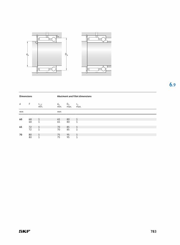
60 85 34 – 60,5 114 9,58 18 14,3 0,77 6 000 6 700 0,59 NKIA 5912 60 68 1 65 80 185 38 34 60,5 114 9,58 18 14,3 0,77 6 000 6 700 0,6 NKIB 5912 68 1 65 80 1
65 90 34 – 61,6 120 9,96 19,2 14,6 0,816 5 600 6 300 0,64 NKIA 5913 65 72 1 70 85 190 38 34 61,6 120 9,96 19,2 14,6 0,816 5 600 6 300 0,64 NKIB 5913 72 1 70 85 1
70 100 40 – 84,2 163 13,2 25 20,8 1,05 5 000 5 600 0,98 NKIA 5914 70 80 1 75 95 1100 45 40 84,2 163 13,2 25 20,8 1,05 5 000 5 600 0,99 NKIB 5914 80 1 75 95 1
6 .9
Principal dimensions Basic load ratings Fatigue load
limitsSpeed ratings Mass Designation Dimensions Abutment and fillet dimensions
radial axial Reference speed
Limiting speeddynamic static dynamic static radial axial
d D B C C C0 C C0 Pu Pu d F r1,2 da Da ramin. min. max. max.
mm kN kN kN r/min kg – mm mm
Dada
ra
ra
783

7 14 18 2,81 2,75 3,45 5 0,29 0,186 0,13 10 000 11 000 0,014 NX 7 TN1) 7 4,7 7 0,3 9,6 12 10 0,3 – – – – SW 1414 18 2,81 2,75 3,45 5 0,29 0,186 0,13 10 000 6 000 0,014 NX 7 ZTN1) 4,7 7 0,3 9,6 12 10 0,3 – – – – SW 14
10 19 18 4,95 4,55 5,07 8,5 0,53 0,31 0,38 8 500 9 500 0,025 NX 10 10 4,7 10 0,3 14,6 17 10 0,3 6 10 10 IR 6x10x10 IS1 SW 1919 18 4,95 4,55 5,07 8,5 0,53 0,31 0,38 8 500 5 600 0,025 NX 10 Z 4,7 10 0,3 14,6 17 10 0,3 6 10 10 IR 6x10x10 IS1 SW 19
12 21 18 5,39 5,2 5,27 9,65 0,61 0,355 0,48 8 000 9 000 0,028 NX 12 12 4,7 12 0,3 16,6 19 10 0,3 8 12 10 IR 8x12x10 IS1 SW 2121 18 5,39 5,2 5,27 9,65 0,61 0,355 0,48 8 000 5 300 0,028 NX 12 Z 4,7 12 0,3 16,6 19 10 0,3 8 12 10 IR 8x12x10 IS1 SW 21
15 24 28 11 14 6,18 12,2 1,66 0,45 0,77 7 500 8 500 0,048 NX 15 15 8 15 0,3 19 22 12,2 0,3 12 15 16 IR 12x15 x16 SW 2424 28 11 14 6,18 12,2 1,66 0,45 0,77 7 500 5 300 0,048 NX 15 Z 8 15 0,3 19 22 12,2 0,3 12 15 16 IR 12x15 x16 SW 24
17 26 28 12,1 16,6 6,37 13,4 1,96 0,5 0,93 7 000 8 500 0,053 NX 17 17 8 17 0,3 21 24 12,2 0,3 14 17 17 IR 14x17 x17 SW 2626 28 12,1 16,6 6,37 13,4 1,96 0,5 0,93 7 000 5 000 0,053 NX 17 Z 8 17 0,3 21 24 12,2 0,3 14 17 17 IR 14x17 x17 SW 26
20 30 28 13,2 19,3 7,8 17,3 2,28 0,64 1,6 6 300 7 500 0,068 NX 20 20 8 20 0,3 25 28 12,2 0,3 17 20 16 IR 17x20 x16 SW 3030 28 13,2 19,3 7,8 17,3 2,28 0,64 1,6 6 300 4 500 0,068 NX 20 Z 8 20 0,3 25 28 12,2 0,3 17 20 16 IR 17x20 x16 SW 30
25 37 30 15,1 24,5 12,4 28,5 2,9 1,06 4,2 5 600 6 300 0,12 NX 25 25 8 25 0,3 31,6 35 14,2 0,3 20 25 16 IR 20x25x16 IS1 SW 3737 30 15,1 24,5 12,4 28,5 2,9 1,06 4,2 5 600 3 800 0,12 NX 25 Z 8 25 0,3 31,6 35 14,2 0,3 20 25 16 IR 20x25x16 IS1 SW 37
30 42 30 22,9 38 12,7 32,5 4,8 1,2 5,5 5 300 6 000 0,13 NX 30 30 10 30 0,3 36,5 40 14,2 0,3 25 30 20 IR 25x30 x20 SW 4242 30 22,9 38 12,7 32,5 4,8 1,2 5,5 5 300 3 600 0,13 NX 30 Z 10 30 0,3 36,5 40 14,2 0,3 25 30 20 IR 25x30 x20 SW 42
35 47 30 24,6 45 13,5 38 5,6 1,4 7,5 5 000 5 600 0,16 NX 35 35 10 35 0,3 40,5 45 14,2 0,3 30 35 20 IR 30x35 x20 SW 4747 30 24,6 45 13,5 38 5,6 1,4 7,5 5 000 3 400 0,16 NX 35 Z 10 35 0,3 40,5 45 14,2 0,3 30 35 20 IR 30x35 x20 SW 47
Fw
C1
C
r1
D
r1
r2
r2
d
6.10 Needle roller / thrust ball bearings, full complement thrust bearingFw 7 – 35 mm
Principal dimensions
Basic load ratings Fatigue load limits
Min. load factor
Speed ratings Mass Designation Dimensions Abutment and fillet dimensions Appropriate inner ring1) Appropriate snap ring2)radial axial Reference
speedLimiting speed
Dimensions Designationdynamic static dynamic static radial axial Designation
Fw D C C C0 C C0 Pu Pu A Fw C1 d r1,2 da Da Ca ra di F Bimin. min. max. max.
mm kN kN kN – r/min kg – mm mm mm – –
1) Radial bearing with inserted closure ring.
NX NX .. Z
784
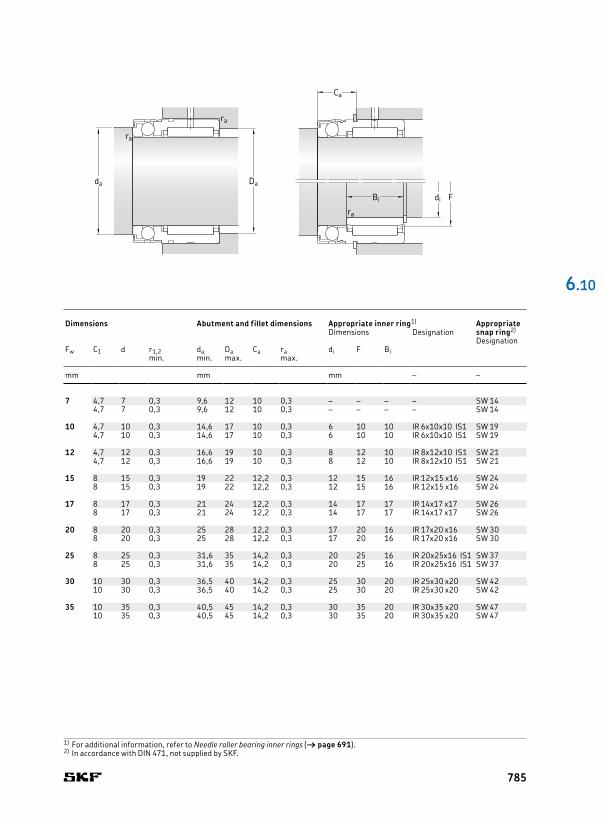
7 14 18 2,81 2,75 3,45 5 0,29 0,186 0,13 10 000 11 000 0,014 NX 7 TN1) 7 4,7 7 0,3 9,6 12 10 0,3 – – – – SW 1414 18 2,81 2,75 3,45 5 0,29 0,186 0,13 10 000 6 000 0,014 NX 7 ZTN1) 4,7 7 0,3 9,6 12 10 0,3 – – – – SW 14
10 19 18 4,95 4,55 5,07 8,5 0,53 0,31 0,38 8 500 9 500 0,025 NX 10 10 4,7 10 0,3 14,6 17 10 0,3 6 10 10 IR 6x10x10 IS1 SW 1919 18 4,95 4,55 5,07 8,5 0,53 0,31 0,38 8 500 5 600 0,025 NX 10 Z 4,7 10 0,3 14,6 17 10 0,3 6 10 10 IR 6x10x10 IS1 SW 19
12 21 18 5,39 5,2 5,27 9,65 0,61 0,355 0,48 8 000 9 000 0,028 NX 12 12 4,7 12 0,3 16,6 19 10 0,3 8 12 10 IR 8x12x10 IS1 SW 2121 18 5,39 5,2 5,27 9,65 0,61 0,355 0,48 8 000 5 300 0,028 NX 12 Z 4,7 12 0,3 16,6 19 10 0,3 8 12 10 IR 8x12x10 IS1 SW 21
15 24 28 11 14 6,18 12,2 1,66 0,45 0,77 7 500 8 500 0,048 NX 15 15 8 15 0,3 19 22 12,2 0,3 12 15 16 IR 12x15 x16 SW 2424 28 11 14 6,18 12,2 1,66 0,45 0,77 7 500 5 300 0,048 NX 15 Z 8 15 0,3 19 22 12,2 0,3 12 15 16 IR 12x15 x16 SW 24
17 26 28 12,1 16,6 6,37 13,4 1,96 0,5 0,93 7 000 8 500 0,053 NX 17 17 8 17 0,3 21 24 12,2 0,3 14 17 17 IR 14x17 x17 SW 2626 28 12,1 16,6 6,37 13,4 1,96 0,5 0,93 7 000 5 000 0,053 NX 17 Z 8 17 0,3 21 24 12,2 0,3 14 17 17 IR 14x17 x17 SW 26
20 30 28 13,2 19,3 7,8 17,3 2,28 0,64 1,6 6 300 7 500 0,068 NX 20 20 8 20 0,3 25 28 12,2 0,3 17 20 16 IR 17x20 x16 SW 3030 28 13,2 19,3 7,8 17,3 2,28 0,64 1,6 6 300 4 500 0,068 NX 20 Z 8 20 0,3 25 28 12,2 0,3 17 20 16 IR 17x20 x16 SW 30
25 37 30 15,1 24,5 12,4 28,5 2,9 1,06 4,2 5 600 6 300 0,12 NX 25 25 8 25 0,3 31,6 35 14,2 0,3 20 25 16 IR 20x25x16 IS1 SW 3737 30 15,1 24,5 12,4 28,5 2,9 1,06 4,2 5 600 3 800 0,12 NX 25 Z 8 25 0,3 31,6 35 14,2 0,3 20 25 16 IR 20x25x16 IS1 SW 37
30 42 30 22,9 38 12,7 32,5 4,8 1,2 5,5 5 300 6 000 0,13 NX 30 30 10 30 0,3 36,5 40 14,2 0,3 25 30 20 IR 25x30 x20 SW 4242 30 22,9 38 12,7 32,5 4,8 1,2 5,5 5 300 3 600 0,13 NX 30 Z 10 30 0,3 36,5 40 14,2 0,3 25 30 20 IR 25x30 x20 SW 42
35 47 30 24,6 45 13,5 38 5,6 1,4 7,5 5 000 5 600 0,16 NX 35 35 10 35 0,3 40,5 45 14,2 0,3 30 35 20 IR 30x35 x20 SW 4747 30 24,6 45 13,5 38 5,6 1,4 7,5 5 000 3 400 0,16 NX 35 Z 10 35 0,3 40,5 45 14,2 0,3 30 35 20 IR 30x35 x20 SW 47
6 .10
di
Ca
FBi
ra
Dada
ra
ra
Principal dimensions
Basic load ratings Fatigue load limits
Min. load factor
Speed ratings Mass Designation Dimensions Abutment and fillet dimensions Appropriate inner ring1) Appropriate snap ring2)radial axial Reference
speedLimiting speed
Dimensions Designationdynamic static dynamic static radial axial Designation
Fw D C C C0 C C0 Pu Pu A Fw C1 d r1,2 da Da Ca ra di F Bimin. min. max. max.
mm kN kN kN – r/min kg – mm mm mm – –
1) For additional information, refer to Needle roller bearing inner rings († page 691).2) In accordance with DIN 471, not supplied by SKF.
785
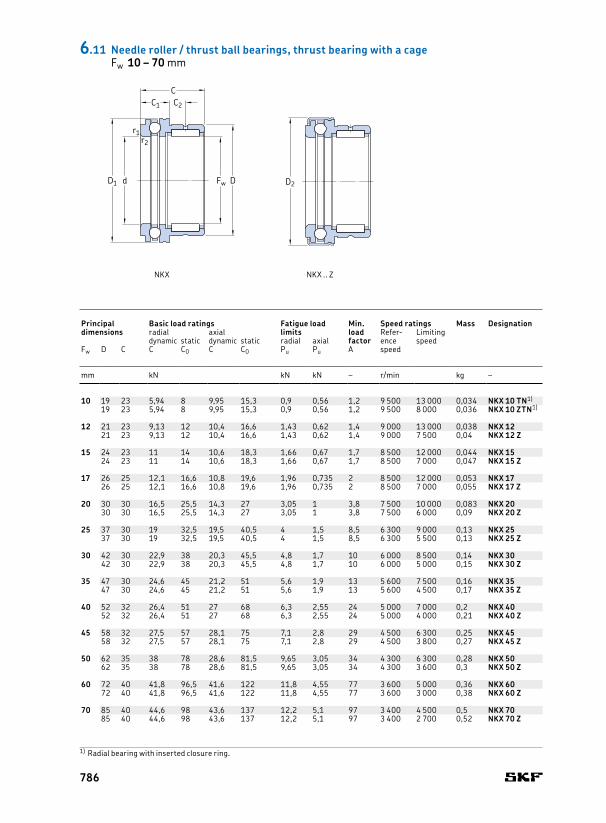
10 19 23 5,94 8 9,95 15,3 0,9 0,56 1,2 9 500 13 000 0,034 NKX 10 TN1) 10 9 6,5 10 24,1 – 0,3 19,7 0,3 0,3 7 10 16 IR 7x10x1619 23 5,94 8 9,95 15,3 0,9 0,56 1,2 9 500 8 000 0,036 NKX 10 ZTN1) 9 6,5 10 – 25,2 0,3 19,7 0,3 0,3 7 10 16 IR 7x10x16
12 21 23 9,13 12 10,4 16,6 1,43 0,62 1,4 9 000 13 000 0,038 NKX 12 12 9 6,5 12 26,1 – 0,3 21,7 0,3 0,3 9 12 16 IR 9x12x1621 23 9,13 12 10,4 16,6 1,43 0,62 1,4 9 000 7 500 0,04 NKX 12 Z 9 6,5 12 – 27,2 0,3 21,7 0,3 0,3 9 12 16 IR 9x12x16
15 24 23 11 14 10,6 18,3 1,66 0,67 1,7 8 500 12 000 0,044 NKX 15 15 9 6,5 15 28,1 – 0,3 23,7 0,3 0,3 12 15 16 IR 12x15x1624 23 11 14 10,6 18,3 1,66 0,67 1,7 8 500 7 000 0,047 NKX 15 Z 9 6,5 15 – 29,2 0,3 23,7 0,3 0,3 12 15 16 IR 12x15x16
17 26 25 12,1 16,6 10,8 19,6 1,96 0,735 2 8 500 12 000 0,053 NKX 17 17 9 8 17 30,1 – 0,3 25,7 0,3 0,3 14 17 17 IR 14x17x1726 25 12,1 16,6 10,8 19,6 1,96 0,735 2 8 500 7 000 0,055 NKX 17 Z 9 8 17 – 31,2 0,3 25,7 0,3 0,3 14 17 17 IR 14x17x17
20 30 30 16,5 25,5 14,3 27 3,05 1 3,8 7 500 10 000 0,083 NKX 20 20 10 10,5 20 35,1 – 0,3 30,7 0,3 0,3 17 20 20 IR 17x20x2030 30 16,5 25,5 14,3 27 3,05 1 3,8 7 500 6 000 0,09 NKX 20 Z 10 10,5 20 – 36,2 0,3 30,7 0,3 0,3 17 20 20 IR 17x20x20
25 37 30 19 32,5 19,5 40,5 4 1,5 8,5 6 300 9 000 0,13 NKX 25 25 11 9,5 25 42,1 – 0,6 37,7 0,6 0,3 20 25 20 IR 20x25x2037 30 19 32,5 19,5 40,5 4 1,5 8,5 6 300 5 500 0,13 NKX 25 Z 11 9,5 25 – 43,2 0,6 37,7 0,6 0,3 20 25 20 IR 20x25x20
30 42 30 22,9 38 20,3 45,5 4,8 1,7 10 6 000 8 500 0,14 NKX 30 30 11 9,5 30 47,1 – 0,6 42,7 0,6 0,3 25 30 20 IR 25x30x2042 30 22,9 38 20,3 45,5 4,8 1,7 10 6 000 5 000 0,15 NKX 30 Z 11 9,5 30 – 48,2 0,6 42,7 0,6 0,3 25 30 20 IR 25x30x20
35 47 30 24,6 45 21,2 51 5,6 1,9 13 5 600 7 500 0,16 NKX 35 35 12 9 35 52,1 – 0,6 47,7 0,6 0,3 30 35 20 IR 30x35x2047 30 24,6 45 21,2 51 5,6 1,9 13 5 600 4 500 0,17 NKX 35 Z 12 9 35 – 53,2 0,6 47,7 0,6 0,3 30 35 20 IR 30x35x20
40 52 32 26,4 51 27 68 6,3 2,55 24 5 000 7 000 0,2 NKX 40 40 13 10 40 60,1 – 0,6 55,7 0,6 0,3 35 40 20 IR 35x40x2052 32 26,4 51 27 68 6,3 2,55 24 5 000 4 000 0,21 NKX 40 Z 13 10 40 – 61,2 0,6 55,7 0,6 0,3 35 40 20 IR 35x40x20
45 58 32 27,5 57 28,1 75 7,1 2,8 29 4 500 6 300 0,25 NKX 45 45 14 9 45 65,2 – 0,6 60,5 0,6 0,3 40 45 20 IR 40x45x2058 32 27,5 57 28,1 75 7,1 2,8 29 4 500 3 800 0,27 NKX 45 Z 14 9 45 – 66,5 0,6 60,5 0,6 0,3 40 45 20 IR 40x45x20
50 62 35 38 78 28,6 81,5 9,65 3,05 34 4 300 6 300 0,28 NKX 50 50 14 10 50 70,2 – 0,6 65,5 0,6 0,6 45 50 25 IR 45x50x2562 35 38 78 28,6 81,5 9,65 3,05 34 4 300 3 600 0,3 NKX 50 Z 14 10 50 – 71,5 0,6 65,5 0,6 0,6 45 50 25 IR 45x50x25
60 72 40 41,8 96,5 41,6 122 11,8 4,55 77 3 600 5 000 0,36 NKX 60 60 17 12 60 85,2 – 1 80,5 1 1 50 60 25 IR 50x60x2572 40 41,8 96,5 41,6 122 11,8 4,55 77 3 600 3 000 0,38 NKX 60 Z 17 12 60 – 86,5 1 80,5 1 1 50 60 25 IR 50x60x25
70 85 40 44,6 98 43,6 137 12,2 5,1 97 3 400 4 500 0,5 NKX 70 70 18 11 70 95,2 – 1 90,5 1 1 60 70 25 IR 60x70x2585 40 44,6 98 43,6 137 12,2 5,1 97 3 400 2 700 0,52 NKX 70 Z 18 11 70 – 96,5 1 90,5 1 1 60 70 25 IR 60x70x25
6.11 Needle roller / thrust ball bearings, thrust bearing with a cageFw 10 – 70 mm
Principal dimensions
Basic load ratings Fatigue load limits
Min. load factor
Speed ratings Mass Designation Dimensions Abutment and fillet dimensions
Appropriate inner ring1)
radial axial Reference speed
Limiting speed
Dimensions Designationdynamic static dynamic static radial axial
Fw D C C C0 C C0 Pu Pu A Fw C1 C2 d D1 D2 r1,2 da ra rb di F Bimin. min. max. max.
mm kN kN kN – r/min kg – mm mm mm –
1) Radial bearing with inserted closure ring.
D2Fw
C1 C2
C
r1
Dd
r2
D1
NKX NKX .. Z
786
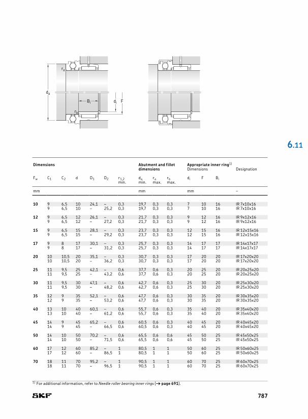
10 19 23 5,94 8 9,95 15,3 0,9 0,56 1,2 9 500 13 000 0,034 NKX 10 TN1) 10 9 6,5 10 24,1 – 0,3 19,7 0,3 0,3 7 10 16 IR 7x10x1619 23 5,94 8 9,95 15,3 0,9 0,56 1,2 9 500 8 000 0,036 NKX 10 ZTN1) 9 6,5 10 – 25,2 0,3 19,7 0,3 0,3 7 10 16 IR 7x10x16
12 21 23 9,13 12 10,4 16,6 1,43 0,62 1,4 9 000 13 000 0,038 NKX 12 12 9 6,5 12 26,1 – 0,3 21,7 0,3 0,3 9 12 16 IR 9x12x1621 23 9,13 12 10,4 16,6 1,43 0,62 1,4 9 000 7 500 0,04 NKX 12 Z 9 6,5 12 – 27,2 0,3 21,7 0,3 0,3 9 12 16 IR 9x12x16
15 24 23 11 14 10,6 18,3 1,66 0,67 1,7 8 500 12 000 0,044 NKX 15 15 9 6,5 15 28,1 – 0,3 23,7 0,3 0,3 12 15 16 IR 12x15x1624 23 11 14 10,6 18,3 1,66 0,67 1,7 8 500 7 000 0,047 NKX 15 Z 9 6,5 15 – 29,2 0,3 23,7 0,3 0,3 12 15 16 IR 12x15x16
17 26 25 12,1 16,6 10,8 19,6 1,96 0,735 2 8 500 12 000 0,053 NKX 17 17 9 8 17 30,1 – 0,3 25,7 0,3 0,3 14 17 17 IR 14x17x1726 25 12,1 16,6 10,8 19,6 1,96 0,735 2 8 500 7 000 0,055 NKX 17 Z 9 8 17 – 31,2 0,3 25,7 0,3 0,3 14 17 17 IR 14x17x17
20 30 30 16,5 25,5 14,3 27 3,05 1 3,8 7 500 10 000 0,083 NKX 20 20 10 10,5 20 35,1 – 0,3 30,7 0,3 0,3 17 20 20 IR 17x20x2030 30 16,5 25,5 14,3 27 3,05 1 3,8 7 500 6 000 0,09 NKX 20 Z 10 10,5 20 – 36,2 0,3 30,7 0,3 0,3 17 20 20 IR 17x20x20
25 37 30 19 32,5 19,5 40,5 4 1,5 8,5 6 300 9 000 0,13 NKX 25 25 11 9,5 25 42,1 – 0,6 37,7 0,6 0,3 20 25 20 IR 20x25x2037 30 19 32,5 19,5 40,5 4 1,5 8,5 6 300 5 500 0,13 NKX 25 Z 11 9,5 25 – 43,2 0,6 37,7 0,6 0,3 20 25 20 IR 20x25x20
30 42 30 22,9 38 20,3 45,5 4,8 1,7 10 6 000 8 500 0,14 NKX 30 30 11 9,5 30 47,1 – 0,6 42,7 0,6 0,3 25 30 20 IR 25x30x2042 30 22,9 38 20,3 45,5 4,8 1,7 10 6 000 5 000 0,15 NKX 30 Z 11 9,5 30 – 48,2 0,6 42,7 0,6 0,3 25 30 20 IR 25x30x20
35 47 30 24,6 45 21,2 51 5,6 1,9 13 5 600 7 500 0,16 NKX 35 35 12 9 35 52,1 – 0,6 47,7 0,6 0,3 30 35 20 IR 30x35x2047 30 24,6 45 21,2 51 5,6 1,9 13 5 600 4 500 0,17 NKX 35 Z 12 9 35 – 53,2 0,6 47,7 0,6 0,3 30 35 20 IR 30x35x20
40 52 32 26,4 51 27 68 6,3 2,55 24 5 000 7 000 0,2 NKX 40 40 13 10 40 60,1 – 0,6 55,7 0,6 0,3 35 40 20 IR 35x40x2052 32 26,4 51 27 68 6,3 2,55 24 5 000 4 000 0,21 NKX 40 Z 13 10 40 – 61,2 0,6 55,7 0,6 0,3 35 40 20 IR 35x40x20
45 58 32 27,5 57 28,1 75 7,1 2,8 29 4 500 6 300 0,25 NKX 45 45 14 9 45 65,2 – 0,6 60,5 0,6 0,3 40 45 20 IR 40x45x2058 32 27,5 57 28,1 75 7,1 2,8 29 4 500 3 800 0,27 NKX 45 Z 14 9 45 – 66,5 0,6 60,5 0,6 0,3 40 45 20 IR 40x45x20
50 62 35 38 78 28,6 81,5 9,65 3,05 34 4 300 6 300 0,28 NKX 50 50 14 10 50 70,2 – 0,6 65,5 0,6 0,6 45 50 25 IR 45x50x2562 35 38 78 28,6 81,5 9,65 3,05 34 4 300 3 600 0,3 NKX 50 Z 14 10 50 – 71,5 0,6 65,5 0,6 0,6 45 50 25 IR 45x50x25
60 72 40 41,8 96,5 41,6 122 11,8 4,55 77 3 600 5 000 0,36 NKX 60 60 17 12 60 85,2 – 1 80,5 1 1 50 60 25 IR 50x60x2572 40 41,8 96,5 41,6 122 11,8 4,55 77 3 600 3 000 0,38 NKX 60 Z 17 12 60 – 86,5 1 80,5 1 1 50 60 25 IR 50x60x25
70 85 40 44,6 98 43,6 137 12,2 5,1 97 3 400 4 500 0,5 NKX 70 70 18 11 70 95,2 – 1 90,5 1 1 60 70 25 IR 60x70x2585 40 44,6 98 43,6 137 12,2 5,1 97 3 400 2 700 0,52 NKX 70 Z 18 11 70 – 96,5 1 90,5 1 1 60 70 25 IR 60x70x25
6 .11
Principal dimensions
Basic load ratings Fatigue load limits
Min. load factor
Speed ratings Mass Designation Dimensions Abutment and fillet dimensions
Appropriate inner ring1)
radial axial Reference speed
Limiting speed
Dimensions Designationdynamic static dynamic static radial axial
Fw D C C C0 C C0 Pu Pu A Fw C1 C2 d D1 D2 r1,2 da ra rb di F Bimin. min. max. max.
mm kN kN kN – r/min kg – mm mm mm –
1) For additional information, refer to Needle roller bearing inner rings († page 691).
di FBi
rb
ra
da
787

15 24 23 11 14 11,2 27 1,66 2,45 0,058 4 300 8 500 0,042 NKXR 15 15 9 6,5 15 28,1 – 0,3 23,7 0,3 0,3 12 15 16 IR 12x15x1624 23 11 14 11,2 27 1,66 2,45 0,058 4 300 8 500 0,045 NKXR 15 Z 9 6,5 15 – 29,2 0,3 23,7 0,3 0,3 12 15 16 IR 12x15x16
17 26 25 12,1 16,6 12,2 31,5 1,96 2,85 0,079 4 300 8 500 0,05 NKXR 17 17 9 8 17 30,1 – 0,3 25,7 0,3 0,3 14 17 17 IR 14x17x1726 25 12,1 16,6 12,2 31,5 1,96 2,85 0,079 4 300 8 500 0,053 NKXR 17 Z 9 8 17 – 31,2 0,3 25,7 0,3 0,3 14 17 17 IR 14x17x17
20 30 30 16,5 25,5 18,6 48 3,05 4,65 0,18 3 800 7 500 0,08 NKXR 20 20 10 10,5 20 35,1 – 0,3 30,7 0,3 0,3 17 20 20 IR 17x20x2030 30 16,5 25,5 18,6 48 3,05 4,65 0,18 3 800 7 500 0,084 NKXR 20 Z 10 10,5 20 – 36,2 0,3 30,7 0,3 0,3 17 20 20 IR 17x20x20
25 37 30 19 32,5 25 69,5 4 6,8 0,39 3 200 6 300 0,12 NKXR 25 25 11 9,5 25 42,1 – 0,6 37,7 0,6 0,3 20 25 20 IR 20x25x2037 30 19 32,5 25 69,5 4 6,8 0,39 3 200 6 300 0,13 NKXR 25 Z 11 9,5 25 – 43,2 0,6 37,7 0,6 0,3 20 25 20 IR 20x25x20
30 42 30 22,9 38 27 78 4,8 7,65 0,49 3 000 6 000 0,14 NKXR 30 30 11 9,5 30 47,1 – 0,6 42,7 0,6 0,3 25 30 20 IR 25x30x2042 30 22,9 38 27 78 4,8 7,65 0,49 3 000 6 000 0,14 NKXR 30 Z 11 9,5 30 – 48,2 0,6 42,7 0,6 0,3 25 30 20 IR 25x30x20
35 47 30 24,6 45 29 93 5,6 9,15 0,69 2 800 5 600 0,16 NKXR 35 35 12 9 35 52,1 – 0,6 47,7 0,6 0,3 30 35 20 IR 30x35x2047 30 24,6 45 29 93 5,6 9,15 0,69 2 800 5 600 0,17 NKXR 35 Z 12 9 35 – 53,2 0,6 47,7 0,6 0,3 30 35 20 IR 30x35x20
40 52 32 26,4 51 43 137 6,3 13,7 1,5 2 400 5 000 0,2 NKXR 40 40 13 10 40 60,1 – 0,6 55,7 0,6 0,3 35 40 20 IR 35x40x2052 32 26,4 51 43 137 6,3 13,7 1,5 2 400 5 000 0,21 NKXR 40 Z 13 10 40 – 61,2 0,6 55,7 0,6 0,3 35 40 20 IR 35x40x20
45 58 32 27,5 57 45 153 7,1 15,3 1,85 2 200 4 500 0,24 NKXR 45 45 14 9 45 65,2 – 0,6 60,6 0,6 0,3 40 45 20 IR 40x45x2058 32 27,5 57 45 153 7,1 15,3 1,85 2 200 4 500 0,26 NKXR 45 Z 14 9 45 – 71,5 0,6 60,6 0,6 0,3 40 45 20 IR 40x45x20
50 62 35 38 78 47,5 166 9,65 16,6 2,2 2 200 4 300 0,27 NKXR 50 50 14 10 50 70,2 – 0,6 65,5 0,6 0,6 45 50 25 IR 45x50x2562 35 38 78 47,5 166 9,65 16,6 2,2 2 200 4 300 0,29 NKXR 50 Z 14 10 50 – 71,5 0,6 65,5 0,6 0,6 45 50 25 IR 45x50x25
6.12 Needle roller / cylindrical roller thrust bearingsFw 15 – 50 mm
Principal dimensions
Basic load ratings Fatigue load limits
Min. load factor
Speed ratings Mass Designation Dimensions Abutment and fillet dimensions
Appropriate inner ring1)
radial axial Reference speed
Limiting speed
Dimensions Designationdynamic static dynamic static radial axial
Fw D C C C0 C C0 Pu Pu A Fw C1 C2 d D1 D2 r1,2 da ra rb di F Bimin. min. max. max.
mm kN kN kN – r/min kg – mm mm mm –
D2Fw
C1 C2
C
r1
Dd
r2
r2
r1
D1
NKXR NKXR .. Z
788

15 24 23 11 14 11,2 27 1,66 2,45 0,058 4 300 8 500 0,042 NKXR 15 15 9 6,5 15 28,1 – 0,3 23,7 0,3 0,3 12 15 16 IR 12x15x1624 23 11 14 11,2 27 1,66 2,45 0,058 4 300 8 500 0,045 NKXR 15 Z 9 6,5 15 – 29,2 0,3 23,7 0,3 0,3 12 15 16 IR 12x15x16
17 26 25 12,1 16,6 12,2 31,5 1,96 2,85 0,079 4 300 8 500 0,05 NKXR 17 17 9 8 17 30,1 – 0,3 25,7 0,3 0,3 14 17 17 IR 14x17x1726 25 12,1 16,6 12,2 31,5 1,96 2,85 0,079 4 300 8 500 0,053 NKXR 17 Z 9 8 17 – 31,2 0,3 25,7 0,3 0,3 14 17 17 IR 14x17x17
20 30 30 16,5 25,5 18,6 48 3,05 4,65 0,18 3 800 7 500 0,08 NKXR 20 20 10 10,5 20 35,1 – 0,3 30,7 0,3 0,3 17 20 20 IR 17x20x2030 30 16,5 25,5 18,6 48 3,05 4,65 0,18 3 800 7 500 0,084 NKXR 20 Z 10 10,5 20 – 36,2 0,3 30,7 0,3 0,3 17 20 20 IR 17x20x20
25 37 30 19 32,5 25 69,5 4 6,8 0,39 3 200 6 300 0,12 NKXR 25 25 11 9,5 25 42,1 – 0,6 37,7 0,6 0,3 20 25 20 IR 20x25x2037 30 19 32,5 25 69,5 4 6,8 0,39 3 200 6 300 0,13 NKXR 25 Z 11 9,5 25 – 43,2 0,6 37,7 0,6 0,3 20 25 20 IR 20x25x20
30 42 30 22,9 38 27 78 4,8 7,65 0,49 3 000 6 000 0,14 NKXR 30 30 11 9,5 30 47,1 – 0,6 42,7 0,6 0,3 25 30 20 IR 25x30x2042 30 22,9 38 27 78 4,8 7,65 0,49 3 000 6 000 0,14 NKXR 30 Z 11 9,5 30 – 48,2 0,6 42,7 0,6 0,3 25 30 20 IR 25x30x20
35 47 30 24,6 45 29 93 5,6 9,15 0,69 2 800 5 600 0,16 NKXR 35 35 12 9 35 52,1 – 0,6 47,7 0,6 0,3 30 35 20 IR 30x35x2047 30 24,6 45 29 93 5,6 9,15 0,69 2 800 5 600 0,17 NKXR 35 Z 12 9 35 – 53,2 0,6 47,7 0,6 0,3 30 35 20 IR 30x35x20
40 52 32 26,4 51 43 137 6,3 13,7 1,5 2 400 5 000 0,2 NKXR 40 40 13 10 40 60,1 – 0,6 55,7 0,6 0,3 35 40 20 IR 35x40x2052 32 26,4 51 43 137 6,3 13,7 1,5 2 400 5 000 0,21 NKXR 40 Z 13 10 40 – 61,2 0,6 55,7 0,6 0,3 35 40 20 IR 35x40x20
45 58 32 27,5 57 45 153 7,1 15,3 1,85 2 200 4 500 0,24 NKXR 45 45 14 9 45 65,2 – 0,6 60,6 0,6 0,3 40 45 20 IR 40x45x2058 32 27,5 57 45 153 7,1 15,3 1,85 2 200 4 500 0,26 NKXR 45 Z 14 9 45 – 71,5 0,6 60,6 0,6 0,3 40 45 20 IR 40x45x20
50 62 35 38 78 47,5 166 9,65 16,6 2,2 2 200 4 300 0,27 NKXR 50 50 14 10 50 70,2 – 0,6 65,5 0,6 0,6 45 50 25 IR 45x50x2562 35 38 78 47,5 166 9,65 16,6 2,2 2 200 4 300 0,29 NKXR 50 Z 14 10 50 – 71,5 0,6 65,5 0,6 0,6 45 50 25 IR 45x50x25
6 .12
Principal dimensions
Basic load ratings Fatigue load limits
Min. load factor
Speed ratings Mass Designation Dimensions Abutment and fillet dimensions
Appropriate inner ring1)
radial axial Reference speed
Limiting speed
Dimensions Designationdynamic static dynamic static radial axial
Fw D C C C0 C C0 Pu Pu A Fw C1 C2 d D1 D2 r1,2 da ra rb di F Bimin. min. max. max.
mm kN kN kN – r/min kg – mm mm mm –
1) For additional information, refer to Needle roller bearing inner rings († page 691).
di FBi
rb
ra
da
789

5 8 12 0,3 0,003 IR 5x8x128 16 0,3 0,004 IR 5x8x16
6 9 12 0,3 0,003 IR 6x9x129 16 0,3 0,004 IR 6x9x1610 10 0,3 0,004 IR 6x10x1010 10 0,3 0,004 IR 6x10x10 IS1
7 10 10,5 0,3 0,003 IR 7x10x10.510 10,5 0,3 0,003 LR 7x10x10.510 12 0,3 0,004 IR 7x10x1210 16 0,3 0,005 IR 7x10x16
8 12 10 0,3 0,005 IR 8x12x1012 10 0,3 0,005 IR 8x12x10 IS112 10,5 0,3 0,005 IR 8x12x10.512 10,5 0,3 0,005 LR 8x12x10.512 12,5 0,3 0,006 IR 8x12x12.512 12,5 0,3 0,006 LR 8x12x12.5
9 12 12 0,3 0,004 IR 9x12x1212 16 0,3 0,006 IR 9x12x16
10 13 12,5 0,3 0,005 IR 10x13x12.513 12,5 0,3 0,005 LR 10x13x12.514 12 0,3 0,007 IR 10x14x12 IS114 13 0,3 0,007 IR 10x14x1314 16 0,3 0,009 IR 10x14x1614 20 0,3 0,012 IR 10x14x20
12 15 12 0,3 0,006 IR 12x15x1215 12,5 0,3 0,006 IR 12x15x12.515 12,5 0,3 0,006 LR 12x15x12.5
15 16 0,3 0,008 IR 12x15x1615 16,5 0,3 0,008 IR 12x15x16.515 16,5 0,3 0,008 LR 12x15x16.515 22,5 0,3 0,011 IR 12x15x22.515 22,5 0,3 0,011 LR 12x15x22.5
16 12 0,3 0,008 IR 12x16x12 IS116 13 0,3 0,009 IR 12x16x1316 16 0,3 0,011 IR 12x16x1616 20 0,3 0,014 IR 12x16x2016 22 0,3 0,015 IR 12x16x22
14 17 17 0,3 0,01 IR 14x17x17
15 18 12,5 0,3 0,007 LR 15x18x12.518 16 0,3 0,009 IR 15x18x1618 16,5 0,3 0,01 IR 15x18x16.518 16,5 0,3 0,01 LR 15x18x16.5
19 16 0,3 0,013 IR 15x19x1619 20 0,3 0,016 IR 15x19x2020 12 0,3 0,012 IR 15x20x12 IS120 13 0,3 0,014 IR 15x20x1320 23 0,3 0,024 IR 15x20x23
r30°
d
r1r2
F
B
6.13 Needle roller bearing inner ringsd 5 – 45 mm
Dimensions Mass Designation
d F B r, r1,2min.
mm kg –
Dimensions Mass Designation
d F B r, r1,2min.
mm kg –
IR IR .. IS1 LR
790
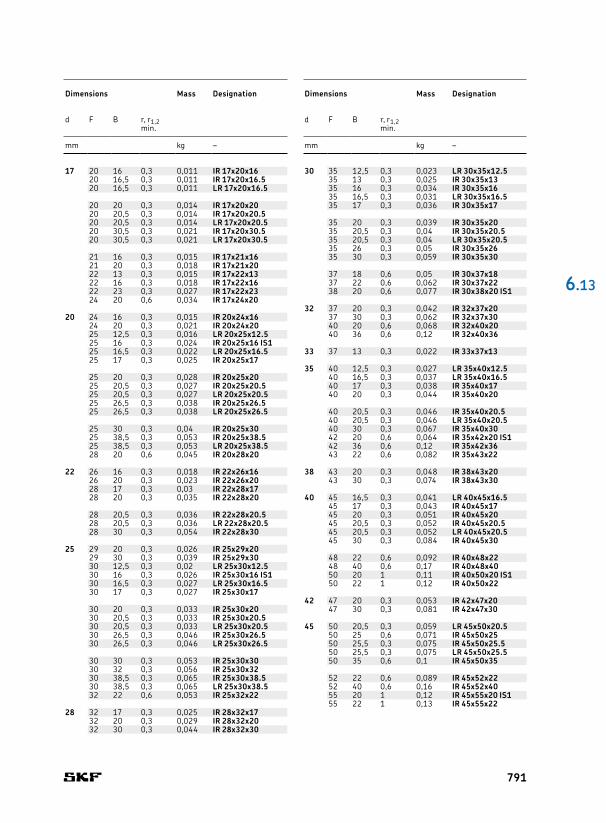
30 35 12,5 0,3 0,023 LR 30x35x12.535 13 0,3 0,025 IR 30x35x1335 16 0,3 0,034 IR 30x35x1635 16,5 0,3 0,031 LR 30x35x16.535 17 0,3 0,036 IR 30x35x17
35 20 0,3 0,039 IR 30x35x2035 20,5 0,3 0,04 IR 30x35x20.535 20,5 0,3 0,04 LR 30x35x20.535 26 0,3 0,05 IR 30x35x2635 30 0,3 0,059 IR 30x35x30
37 18 0,6 0,05 IR 30x37x1837 22 0,6 0,062 IR 30x37x2238 20 0,6 0,077 IR 30x38x20 IS1
32 37 20 0,3 0,042 IR 32x37x2037 30 0,3 0,062 IR 32x37x3040 20 0,6 0,068 IR 32x40x2040 36 0,6 0,12 IR 32x40x36
33 37 13 0,3 0,022 IR 33x37x13
35 40 12,5 0,3 0,027 LR 35x40x12.540 16,5 0,3 0,037 LR 35x40x16.540 17 0,3 0,038 IR 35x40x1740 20 0,3 0,044 IR 35x40x20
40 20,5 0,3 0,046 IR 35x40x20.540 20,5 0,3 0,046 LR 35x40x20.540 30 0,3 0,067 IR 35x40x3042 20 0,6 0,064 IR 35x42x20 IS142 36 0,6 0,12 IR 35x42x3643 22 0,6 0,082 IR 35x43x22
38 43 20 0,3 0,048 IR 38x43x2043 30 0,3 0,074 IR 38x43x30
40 45 16,5 0,3 0,041 LR 40x45x16.545 17 0,3 0,043 IR 40x45x1745 20 0,3 0,051 IR 40x45x2045 20,5 0,3 0,052 IR 40x45x20.545 20,5 0,3 0,052 LR 40x45x20.545 30 0,3 0,084 IR 40x45x30
48 22 0,6 0,092 IR 40x48x2248 40 0,6 0,17 IR 40x48x4050 20 1 0,11 IR 40x50x20 IS150 22 1 0,12 IR 40x50x22
42 47 20 0,3 0,053 IR 42x47x2047 30 0,3 0,081 IR 42x47x30
45 50 20,5 0,3 0,059 LR 45x50x20.550 25 0,6 0,071 IR 45x50x2550 25,5 0,3 0,075 IR 45x50x25.550 25,5 0,3 0,075 LR 45x50x25.550 35 0,6 0,1 IR 45x50x35
52 22 0,6 0,089 IR 45x52x2252 40 0,6 0,16 IR 45x52x4055 20 1 0,12 IR 45x55x20 IS155 22 1 0,13 IR 45x55x22
17 20 16 0,3 0,011 IR 17x20x1620 16,5 0,3 0,011 IR 17x20x16.520 16,5 0,3 0,011 LR 17x20x16.5
20 20 0,3 0,014 IR 17x20x2020 20,5 0,3 0,014 IR 17x20x20.520 20,5 0,3 0,014 LR 17x20x20.520 30,5 0,3 0,021 IR 17x20x30.520 30,5 0,3 0,021 LR 17x20x30.5
21 16 0,3 0,015 IR 17x21x1621 20 0,3 0,018 IR 17x21x2022 13 0,3 0,015 IR 17x22x1322 16 0,3 0,018 IR 17x22x1622 23 0,3 0,027 IR 17x22x2324 20 0,6 0,034 IR 17x24x20
20 24 16 0,3 0,015 IR 20x24x1624 20 0,3 0,021 IR 20x24x2025 12,5 0,3 0,016 LR 20x25x12.525 16 0,3 0,024 IR 20x25x16 IS125 16,5 0,3 0,022 LR 20x25x16.525 17 0,3 0,025 IR 20x25x17
25 20 0,3 0,028 IR 20x25x2025 20,5 0,3 0,027 IR 20x25x20.525 20,5 0,3 0,027 LR 20x25x20.525 26,5 0,3 0,038 IR 20x25x26.525 26,5 0,3 0,038 LR 20x25x26.5
25 30 0,3 0,04 IR 20x25x3025 38,5 0,3 0,053 IR 20x25x38.525 38,5 0,3 0,053 LR 20x25x38.528 20 0,6 0,045 IR 20x28x20
22 26 16 0,3 0,018 IR 22x26x1626 20 0,3 0,023 IR 22x26x2028 17 0,3 0,03 IR 22x28x1728 20 0,3 0,035 IR 22x28x20
28 20,5 0,3 0,036 IR 22x28x20.528 20,5 0,3 0,036 LR 22x28x20.528 30 0,3 0,054 IR 22x28x30
25 29 20 0,3 0,026 IR 25x29x2029 30 0,3 0,039 IR 25x29x3030 12,5 0,3 0,02 LR 25x30x12.530 16 0,3 0,026 IR 25x30x16 IS130 16,5 0,3 0,027 LR 25x30x16.530 17 0,3 0,027 IR 25x30x17
30 20 0,3 0,033 IR 25x30x2030 20,5 0,3 0,033 IR 25x30x20.530 20,5 0,3 0,033 LR 25x30x20.530 26,5 0,3 0,046 IR 25x30x26.530 26,5 0,3 0,046 LR 25x30x26.5
30 30 0,3 0,053 IR 25x30x3030 32 0,3 0,056 IR 25x30x3230 38,5 0,3 0,065 IR 25x30x38.530 38,5 0,3 0,065 LR 25x30x38.532 22 0,6 0,053 IR 25x32x22
28 32 17 0,3 0,025 IR 28x32x1732 20 0,3 0,029 IR 28x32x2032 30 0,3 0,044 IR 28x32x30
6 .13
Dimensions Mass Designation
d F B r, r1,2min.
mm kg –
Dimensions Mass Designation
d F B r, r1,2min.
mm kg –
791

50 55 20 0,6 0,063 IR 50x55x20 IS155 20,5 0,6 0,064 LR 50x55x20.555 25 0,6 0,078 IR 50x55x2555 35 0,6 0,11 IR 50x55x35
58 22 0,6 0,12 IR 50x58x2258 40 0,6 0,21 IR 50x58x4060 20 1 0,13 IR 50x60x20 IS160 25 1 0,16 IR 50x60x2560 28 1,1 0,18 IR 50x60x28
55 60 25 0,6 0,086 IR 55x60x2560 35 0,6 0,12 IR 55x60x3563 25 1 0,14 IR 55x63x2563 45 1 0,26 IR 55x63x4565 28 1,1 0,2 IR 55x65x28
60 68 25 1 0,15 IR 60x68x2568 35 0,6 0,21 IR 60x68x3568 45 1 0,28 IR 60x68x4570 25 1 0,2 IR 60x70x2570 28 1,1 0,22 IR 60x70x28
65 72 25 1 0,14 IR 65x72x2572 45 1 0,26 IR 65x72x4573 25 1 0,16 IR 65x73x2573 35 1 0,23 IR 65x73x3575 28 1,1 0,23 IR 65x75x28
70 80 25 1 0,22 IR 70x80x2580 30 1 0,27 IR 70x80x3080 35 1 0,31 IR 70x80x3580 54 1 0,49 IR 70x80x54
75 85 25 1 0,24 IR 75x85x2585 30 1 0,29 IR 75x85x3085 35 1 0,34 IR 75x85x3585 54 1 0,52 IR 75x85x54
80 90 25 1 0,25 IR 80x90x2590 30 1 0,3 IR 80x90x3090 35 1 0,36 IR 80x90x3590 54 1 0,56 IR 80x90x54
85 95 26 1 0,28 IR 85x95x2695 36 1 0,39 IR 85x95x36100 35 1,1 0,58 IR 85x100x35100 63 1,1 1,05 IR 85x100x63
90 100 26 1 0,29 IR 90x100x26100 30 1 0,34 IR 90x100x30100 36 1 0,41 IR 90x100x36105 35 1,1 0,61 IR 90x105x35105 63 1,1 1,1 IR 90x105x63
95 105 26 1 0,31 IR 95x105x26105 36 1 0,43 IR 95x105x36110 35 1,1 0,66 IR 95x110x35110 63 1,1 1,15 IR 95x110x63
100 110 30 1,1 0,35 IR 100x110x30110 40 1,1 0,51 IR 100x110x40115 40 1,1 0,78 IR 100x115x40
110 120 30 1 0,41 IR 110x120x30125 40 1,1 0,84 IR 110x125x40
120 130 30 1 0,44 IR 120x130x30135 45 1,1 1,05 IR 120x135x45
130 145 35 1,1 0,86 IR 130x145x35150 50 1,5 1,7 IR 130x150x50
140 155 35 1,1 0,92 IR 140x155x35160 50 1,5 1,8 IR 140x160x50
150 165 40 1,1 1,1 IR 150x165x40
160 175 40 1,1 1,2 IR 160x175x40
170 185 45 1,1 1,45 IR 170x185x45
6.13 Needle roller bearing inner ringsd 50 – 380 mm
Dimensions Mass Designation
d F B r, r1,2min.
mm kg –
Dimensions Mass Designation
d F B r, r1,2min.
mm kg –
r30°
d
r1r2
F
B
IR IR .. IS1 LR
792

180 195 45 1,1 1,5 IR 180x195x45
190 210 50 1,5 2,4 IR 190x210x50
200 220 50 1,5 2,5 IR 200x220x50
220 240 50 1,5 2,75 IR 220x240x50
240 265 60 2 4,6 IR 240x265x60
260 285 60 2 5 IR 260x285x60
280 305 69 2 6,1 IR 280x305x69
300 330 80 2,1 9,2 IR 300x330x80
320 350 80 2,1 9,8 IR 320x350x80
340 370 80 2,1 10 IR 340x370x80
360 390 80 2,1 11 IR 360x390x80
380 415 100 2,1 16,5 IR 380x415x100
6 .13
Dimensions Mass Designation
d F B r, r1,2min.
mm kg –
793

1 7,8 0,1 0,4 0,6 0,048 RN-1x7.8 BF/G2
1,5 5,8 0,1 0,4 0,6 0,081 RN-1.5x5.8 BF/G26,8 0,1 0,4 0,6 0,094 RN-1.5x6.8 BF/G27,8 0,1 0,4 0,6 0,11 RN-1.5x7.8 BF/G29,8 0,1 0,4 0,6 0,14 RN-1.5x9.8 BF/G211,8 0,1 0,4 0,6 0,16 RN-1.5x11.8 BF/G213,8 0,1 0,4 0,6 0,19 RN-1.5x13.8 BF/G2
2 6,3 0,2 0,6 0,8 0,16 RN-2x6.3 BF/G27,8 0,2 0,6 0,8 0,19 RN-2x7.8 BF/G29,8 0,2 0,6 0,8 0,24 RN-2x9.8 BF/G211,8 0,2 0,6 0,8 0,29 RN-2x11.8 BF/G213,8 0,2 0,6 0,8 0,34 RN-2x13.8 BF/G215,8 0,2 0,6 0,8 0,39 RN-2x15.8 BF/G2
17,8 0,2 0,6 0,8 0,44 RN-2x17.8 BF/G219,8 0,2 0,6 0,8 0,49 RN-2x19.8 BF/G221,8 0,2 0,6 0,8 0,54 RN-2x21.8 BF/G2
2,5 7,8 0,2 0,6 0,8 0,3 RN-2.5x7.8 BF/G29,8 0,2 0,6 0,8 0,38 RN-2.5x9.8 BF/G211,8 0,2 0,6 0,8 0,45 RN-2.5x11.8 BF/G213,8 0,2 0,6 0,8 0,53 RN-2.5x13.8 BF/G215,8 0,2 0,6 0,8 0,61 RN-2.5x15.8 BF/G2
17,8 0,2 0,6 0,8 0,69 RN-2.5x17.8 BF/G219,8 0,2 0,6 0,8 0,76 RN-2.5x19.8 BF/G221,8 0,2 0,6 0,8 0,84 RN-2.5x21.8 BF/G223,8 0,2 0,6 0,8 0,92 RN-2.5x23.8 BF/G2
3 9,8 0,2 0,6 0,8 0,54 RN-3x9.8 BF/G211,8 0,2 0,6 0,8 0,65 RN-3x11.8 BF/G213,8 0,2 0,6 0,8 0,77 RN-3x13.8 BF/G215,8 0,2 0,6 0,8 0,88 RN-3x15.8 BF/G217,8 0,2 0,6 0,8 0,99 RN-3x17.8 BF/G219,8 0,2 0,6 0,8 1,1 RN-3x19.8 BF/G2
21,8 0,2 0,6 0,8 1,2 RN-3x21.8 BF/G223,8 0,2 0,6 0,8 1,3 RN-3x23.8 BF/G2
3,5 11,8 0,3 0,8 1 0,89 RN-3.5x11.8 BF/G213,8 0,3 0,8 1 1,05 RN-3.5x13.8 BF/G215,8 0,3 0,8 1 1,2 RN-3.5x15.8 BF/G217,8 0,3 0,8 1 1,35 RN-3.5x17.8 BF/G219,8 0,3 0,8 1 1,5 RN-3.5x19.8 BF/G2
21,8 0,3 0,8 1 1,65 RN-3.5x21.8 BF/G229,8 0,3 0,8 1 2,25 RN-3.5x29.8 BF/G234,8 0,3 0,8 1 2,65 RN-3.5x34.8 BF/G2
4 11,8 0,3 0,8 1 1,15 RN-4x11.8 BF/G213,8 0,3 0,8 1 1,35 RN-4x13.8 BF/G215,8 0,3 0,8 1 1,55 RN-4x15.8 BF/G217,8 0,3 0,8 1 1,75 RN-4x17.8 BF/G219,8 0,3 0,8 1 1,95 RN-4x19.8 BF/G221,8 0,3 0,8 1 2,15 RN-4x21.8 BF/G2
23,8 0,3 0,8 1 2,35 RN-4x23.8 BF/G225,8 0,3 0,8 1 2,55 RN-4x25.8 BF/G227,8 0,3 0,8 1 2,75 RN-4x27.8 BF/G229,8 0,3 0,8 1 2,95 RN-4x29.8 BF/G234,8 0,3 0,8 1 3,45 RN-4x34.8 BF/G239,8 0,3 0,8 1 3,95 RN-4x39.8 BF/G2
5 15,8 0,3 0,8 1 2,45 RN-5x15.8 BF/G219,8 0,3 0,8 1 3,05 RN-5x19.8 BF/G221,8 0,3 0,8 1 3,35 RN-5x21.8 BF/G223,8 0,3 0,8 1 3,65 RN-5x23.8 BF/G225,8 0,3 0,8 1 4 RN-5x25.8 BF/G2
27,8 0,3 0,8 1 4,3 RN-5x27.8 BF/G229,8 0,3 0,8 1 4,6 RN-5x29.8 BF/G234,8 0,3 0,8 1 5,35 RN-5x34.8 BF/G239,8 0,3 0,8 1 6,15 RN-5x39.8 BF/G2
6 17,8 0,3 0,8 1 3,95 RN-6x17.8 BF/G2
Dw
Lw
r1 min
r1 max
r2 min
r2 max
6.14 Needle rollersDw 1 – 6 mm
Dimensions Mass Designation
Dw Lw r1,2 r1 r2min. max. max.
mm g –
Dimensions Mass Designation
Dw Lw r1,2 r1 r2min. max. max.
mm g –
794

skf.com