sketch-based path design - university of torontomccrae/projects/gi09/pathdesign_gi2009.pdf ·...
TRANSCRIPT

Sketch-Based Path DesignJames McCrae∗ Karan Singh†
Dynamic Graphics ProjectUniversity of Toronto
ABSTRACT
We present Drive, a system for the conceptual layout of 3D pathnetworks. Our sketch-based interface allows users to efficiently au-thor path layouts with minimal instruction. Our system incorporatessome new and noteworthy components. We present the break-outlens, a novel widget for interactive graphics, inspired by break-outviews used in engineering visualization. We also make three contri-butions specific to path curve design: First, we extend our previouswork to fit aesthetic paths to sketch strokes with constraints, us-ing piecewise clothoid curves. Second, we determine the height ofpaths above the terrain using a constraint optimization formulationof the occlusion relationships between sketched strokes. Finally,we illustrate examples of terrain sensitive path construction in thecontext of road design: automatically removing foliage, buildingbridges and tunnels across topographic features and constructingroad signs appropriate to the sketched paths.
Index Terms: I.3.3 [Computer Graphics]: Picture/ImageGeneration—Line and curve generation; I.3.6 [Computer Graph-ics]: Methodology and Techniques—Interaction techniques
1 INTRODUCTION
While path layouts are necessary for transportation design (roads,railways, nature trails), they are also important as motion paths foranimation, navigation and visualization in games and virtual envi-ronments. Noted landscape architect Lawrence Halprin [16] pointsout that the design of such paths should emphasize the journey ordriving experience. In other words, the spatio-temporal aesthet-ics of path design are as important as its engineering requirements.Unfortunately, unlike 3D shape design where concept sketchinginterfaces are now abundant, sketch-based path design is largelyunexplored. These shape modeling interfaces [18, 31], GoogleSketchUp, are not suitable for conceptual path layout, forcing pathdesigners to reluctantly work with engineering focused CAD toolssuch as AutoCAD Civil3D.
In this paper we present a coherent sketch-based system, Drive,specifically aimed at conceptual path design. While we often useroad networks as a visual representation of the system (see Fig-ure 1), our system can be adapted to paths representing railways,waterways, nature trails, pipe or power lines, graph networks, net-works of surface patches or general 3D curve based modeling (seeFigure 15).
2 RELATED WORK
Sketch-based interfaces generally have a quick-and-dirty feel tothem that is well-suited to ideation and conceptual prototyping.Relevant to this paper a number of compelling systems have beenproposed for 3D shape modeling [40, 18, 36, 31, 29, 10], cameramotion along a path [17], spatial layout [1, 39], interface design
∗e-mail: [email protected]†e-mail: [email protected]
Figure 1: Views of a road network created within Drive.
[22], animation [11, 35] and the sketching of flora and fauna [2] andarchitectural environments, such as Google SketchUp. The area ofsketch-based path design, however, is largely unexplored.
Various aspects of our system draw upon existing research.Our interface is largely driven by a single lasso menu and quickselection-action phrasing [1]. We draw curves directly projectedonto a terrain much the same way that shape modeling systems[18, 29, 19] project a sketched stroke onto underlying geometry.
Lifting these curves in 3D off the projected geometry or creatingnon-planar curves in general is a difficult problem since sketchedstrokes are inherently 2D in the view-plane. Common solutions tothis problem is to resolve in 3D, strokes sketched in multiple views[8, 20]. Multi-view approaches while mathematically straightfor-ward are suboptimal for a user that has to mentally deconstruct a3D curve into multiple disconnected views. We alleviate this prob-lem using a break-out lens that provides the capability of multiviewediting but in context of the current curve and surrounding environ-ment. While lenses for zooming have existed for some time [6, 24]in interactive visualization, we believe this the first approach to bothview manipulation and editing via a lens using nonlinear projection[4, 9].
Occlusion has been exploited to disambiguate the depth of 3Dorganic shapes [10]. In [10] visible contours of 3D objects areprocessed to build 2D panels that are inflated into 3D shapes likeTeddy [18]. The occluded contours result in overlapping panelswhose depth is solved for by optimizing curvature, orientation anddistance of a panel axis from the sketch plane. Since our paths arethe same width, we simplify drawing by using a single stroke rep-resent the spine of the path. We also satisfy occlusion constraintsusing an optimization formulation better suited to path design than3D shape modeling [10] (see Figures 6, 7).
Interaction techniques commonly represent continuous curves asdensely sampled polylines. Geometric properties for these curves,however, needs to be imposed by the curve creation and editingtechnique [14, 36]. One such geometric property is fairness [13],that attempts to capture the visual aesthetic of a curve. Fairness isclosely related to how little and how smoothly a curve bends. Forplanar curves it has been described as curvature continuity G2, witha small number of segments of almost piecewise linear curvature[13]. The family of curves whose curvature varies linearly with arc-length are known as clothoids. Clothoids have been the subject ofprior research in CAD and transportation design as transition curvessmoothly connecting two curve segments [26, 23] or a spline where
every three consecutive points are fit with a parabola-like clothoidsegment [37]. Discrete formulation of clothoid using nonlinear sub-division have also been proposed [15, 32]. The fairness proper-ties of clothoids have been exploited to generate 2D curves thatapproximate sketched input strokes [25] with better fairness prop-erties than the common fairing approaches of spline fitting [30] ordiscrete smoothing by iterative neighbour averaging [36]. This ap-proach also automatically favours precise line and circular-arc seg-ments which are desirable for transport path layout. A further ad-vantage of fitting analytic curve segments like splines or clothoidsover discrete smoothing methods is that the paths can be regener-ated at arbitrary resolution. We build upon the framework of [25]in this paper to allow precise geometric constraints, necessary forlocal control when editing path networks.
Finally, our design goal is not simply path network creation buta conceptualization of the entire driving experience, in which pathsare an integrated part of the environment on which they are laidout. Programs such as Google Earth and Microsoft Virtual Earthprovide compelling interfaces for visualizing terrain and other 3Denvironments, but do not represent paths with independent geom-etry. Path networks have also been used as an input for the proce-dural modeling of 3D geometry [7]. We handle the construction ofthe evolving environment by integrating it into the path design pro-cess. Creating a path automatically defines a cut-and-fill corridor onthe terrain into which the path is integrated, removing foliage, con-structing bridges, tunnels, path crossings and signage as dictated bythe evolving landscape and path network.
The drive through is executed with a select and play action, al-lowing a user to animate the drive along a selected section of pathviewed from a number of typical vantage points, or with interactivecontrol during animation. There has been research on authoringvirtual flythroughs in the context of scene visualization [38, 34] orproduct design [21, 5]. We also provide a simple select-and-timeaction to alter the pacing of a drive along the path. We are thus ableto quickly author the rough timing of objects or cameras animatingalong motion paths, functionality that is more precise and complexto control in animation systems like Maya.
3 DESIGN GOALS
Our goal of rapidly conceptualizing a 3D driving experiencethrough sketching helps define a number of design principles.
1. A general problem with sketch-based 3D applications is aphilosophical disconnect in that view navigation for 3D sceneunderstanding is critical while traditional sketching is inher-ently a 2D task from a fixed viewpoint. We aim towardsmaintaining the focus on sketching and minimizing interac-tive view navigation.
2. This application is designed not only for game designers andtransport landscape architects but also for novice users with-out exceptional artistic skills, for example, to build customtracks to race on in a gaming environment, or exploring op-tions in designing a path through a thicket from their cottageto a nearby lake. The system should thus be easy to use withlimited instruction and fun to play with, encouraging creativeexploration.
3. As with most concept design applications we would like tokeep user focus on design with a maximal sketching surfaceand without any distractions or cognitive overhead from theUI.
4. While most sketch-based applications attempt to leverage themany degrees of freedom of a pen and tablet, we aim to de-sign an application that is equally operable by a mouse, withminimal use of buttons or mode switching.
5. Finally given the conceptual nature and specific domain ofour design problem, we would like to make many intelligentinferences from sketched strokes in the context of the evolvingenvironment, to maximize the visual impact of each sketchedstroke (as an example, see Figure 6).
Designed and implemented within the context of this system, wedraw attention to four key components:Break-out lens: Inspired by break-out views used to indicate or-thogonal viewpoints in engineering visualization, we develop aninteractive lens that performs a continuous view warp to provide anin-context break-out view (see Figure 14). Important advantages ofthe break-out lens are that its locality elegantly avoids view occlu-sion commonly caused by undulating terrain (see Figure 16) andsketching within the lens allows multi-view 3D curve editing, with-out the handicap of mentally resolving the 3D curve from discon-nected views.Clothoids: Clothoids are the family of spirals whose curvaturevaries linearly with arc-length. They are widely used in transporta-tion engineering, since they can be navigated at constant speed bylinear steering and a constant rate of angular acceleration [26, 37].Recently [25] presented an approach to interactive sketch strokefiltering using clothoid curve fitting. We non-trivially adapt thisapproach to our application, by incorporating geometric constraintsthat allow us to interactively interpolate points, edit curves by overs-ketching and represent closed curves using piecewise clohoids.Crossing paths: We handle arbitrarily complex path crossings bysketching occlusion as breaks in the curve path (see Figure 6). Weprocess the sketched strokes to implicitly join these breaks and de-fine inequalities of path height. We then efficiently solve for heightalong the path as an optimization that minimizes the height of thepath from the terrain, while maximizing the variation of heightneeded to satisfy the occlusion relationships (see Figure 7).Terrain sensitive sketching: Our implementation does not focusspecifically on the construction of path layouts but also on the rapidconceptualization and preview of the entire driving experience. Theterrain is more than a canvas on which to sketch paths, it is an evolv-ing environment into which the paths integrate, with automatic con-struction of bridges, tunnels, road signs and changes in foliage (seeFigure 1, 8, 9).
4 PATH CREATION AND EDITING
Open curves are used for path creation and editing. Users sketchstrokes as 2D polylines in the view plane. Each of these points isthen projected onto a 3D heightfield terrain representation, to cre-ate an unfiltered 3D curve representing a path. We resample the3D curve on the terrain by inserting and deleting points to ensure areasonably even arc-length sampling. This 3D curve is then fit us-ing clothoids in 2D in the XZ-plane, ignoring the height componentY (see Figure 2), as is common in transportation design. The fit-ted curve comprising line, circular-arc and piecewise clothoid seg-ments is discretely sampled and projected back to the 3D geometryto define the spine of the final path along which path geometry isdeformed.
Paths may be extended or edited by oversketching [3]. End-pointproximity and end-tangent alignment of the oversketched path toexisting paths is used to infer whether a new path is created or if anexisting path is extended or edited (see Figure 3). Selected regionsof paths can be deleted using the lasso menu. A path edited byoversketching can be globally refitted using clothoids.
4.1 Clothoid Fitting with Geometric ConstraintsThe clothoid fitting approach of [25], while appropriate for the cre-ation of smooth open paths as well as sharp corners in paths, isunsuitable for creating smooth closed curves or for local path edit-ing. We accomplish this by using the end-point and end-tangent

Figure 2: The sketched curve in the image plane is projected onto theterrain geometry, then projected onto the XZ plane where it is repre-sented as a 2D model consisting of line, circular-arc and clothoidsegments.
Figure 3: Extending a path (top) and editing it (middle) by oversketch-ing. A selected portion is deleted (bottom) using the lasso-menu.
sketched stroke piecewise linear curvature fit
κarc-length
assembled clothoid segments
(a)
(b)
curve alignment: translation curve alignment: rotation
Figure 4: Clothoid fitting: (a) Discrete stroke curvature is approxi-mated as a piecewise linear function uniquely defining clothoid seg-ments. (b) A rigid 2D transform minimizes the weighted least squareserror between the composite clothoid and the sketched stroke.
proximity of closed curves and local path edits as constraints to theclothoid fitting process.
The input to our algorithm is a 2D polyline stroke, and the outputa smooth curve comprising line, circular-arc and clothoid segments.
We first provide a brief overview of the general clothoid fittingapproach given in [25] (see Figure 4). The Frenet-Serret formulais used to compute discrete curvature [28] at vertices of the inputpolyline. A dynamic programming algorithm is then used to fita piecewise linear approximation to the discrete curvature of thestroke as a function of arc-length. A user defined parameter con-trols the tradeoff between fitting error and the number of pieces oflinear curvature. The start and end curvature values of each lin-ear piece uniquely determine a line, circular-arc or clothoid curvesegment. These segments assemble together uniquely with G2 con-tinuity into a single composite curve. The next step involves deter-mining a single 2D rigid transform that aligns this composite curvewith the sketched stroke to minimize the error of the stroke fromthe transformed curve. This transform can be computed efficientlyby formulating the error as a weighted least squares optimizationproblem [27].
For each clothoid segment Ci, we have its curvature space end-points (xP
i ,yPi ) and (xP
i+1,yPi+1). These parameters uniquely map to
a clothoid segment defined by B, that defines how tight the clothoidspiral is, and the start and end parameter values t1 and t2.
B =
√xP
i+1− xPi
π(yPi+1− yP
i ), t1 = yP
i B and t2 = yPi+1B. (1)
Given a geometric constraint we thus determine one or more ex-isting clothoid pieces whose parameters we vary to locally satisfythe given geometric constraints. For instance, to generate a G2 tran-sition when oversketching (see Figure 3) or a closed clothoid curve(see Figure 5) we need to enforce common end-point, end-tangentand end-curvature values.
To close a curve, our approach introduces an additional clothoidsegment (which we call the join-piece) between the first and lastclothoid segments, which provides 5 dimensional variability to sat-isfy the set of constraints. The 5 paramaters we operate on afteradding the join-piece are: the curvature value shared between end-points of the first clothoid piece and the join-piece, the curvaturevalue shared between end-points of the last clothoid piece and thejoin piece, and the arc-lengths of the first, last and join clothoidpieces. We apply gradient descent iteratively to vary these clothoidparameters, in order to minimize
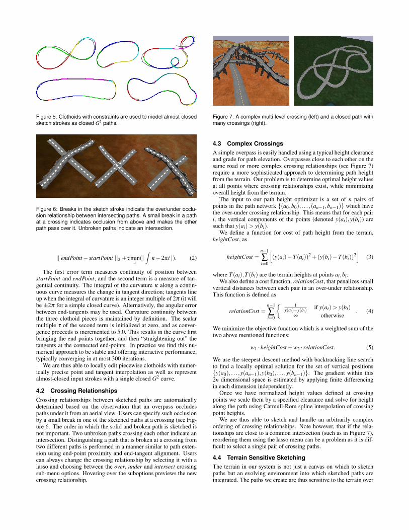
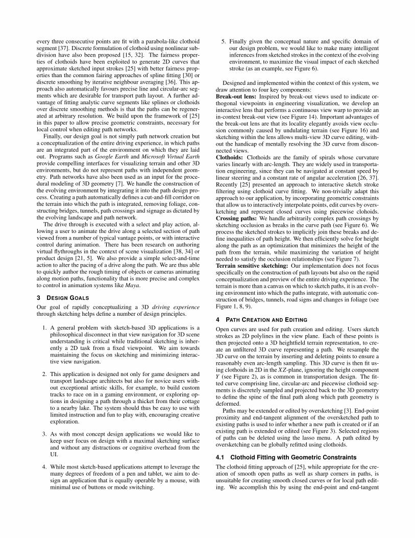
Figure 5: Clothoids with constraints are used to model almost-closedsketch strokes as closed G2 paths.
Figure 6: Breaks in the sketch stroke indicate the over/under occlu-sion relationship between intersecting paths. A small break in a pathat a crossing indicates occlusion from above and makes the otherpath pass over it. Unbroken paths indicate an intersection.
|| endPoint− startPoint ||2 +τ mini
(|∫
κ−2πi |). (2)
The first error term measures continuity of position betweenstartPoint and endPoint, and the second term is a measure of tan-gential continuity. The integral of the curvature κ along a contin-uous curve measures the change in tangent direction; tangents lineup when the integral of curvature is an integer multiple of 2π (it willbe ±2π for a simple closed curve). Alternatively, the angular errorbetween end-tangents may be used. Curvature continuity betweenthe three clothoid pieces is maintained by definition. The scalarmultiple τ of the second term is initialized at zero, and as conver-gence proceeds is incremented to 5.0. This results in the curve firstbringing the end-points together, and then “straightening out” thetangents at the connected end-points. In practice we find this nu-merical approach to be stable and offering interactive performance,typically converging in at most 300 iterations.
We are thus able to locally edit piecewise clothoids with numer-ically precise point and tangent interpolation as well as representalmost-closed input strokes with a single closed G2 curve.
4.2 Crossing RelationshipsCrossing relationships between sketched paths are automaticallydetermined based on the observation that an overpass occludespaths under it from an aerial view. Users can specify such occlusionby a small break in one of the sketched paths at a crossing (see Fig-ure 6. The order in which the solid and broken path is sketched isnot important. Two unbroken paths crossing each other indicate anintersection. Distinguishing a path that is broken at a crossing fromtwo different paths is performed in a manner similar to path exten-sion using end-point proximity and end-tangent alignment. Userscan always change the crossing relationship by selecting it with alasso and choosing between the over, under and intersect crossingsub-menu options. Hovering over the suboptions previews the newcrossing relationship.
Figure 7: A complex multi-level crossing (left) and a closed path withmany crossings (right).
4.3 Complex CrossingsA simple overpass is easily handled using a typical height clearanceand grade for path elevation. Overpasses close to each other on thesame road or more complex crossing relationships (see Figure 7)require a more sophisticated approach to determining path heightfrom the terrain. Our problem is to determine optimal height valuesat all points where crossing relationships exist, while minimizingoverall height from the terrain.
The input to our path height optimizer is a set of n pairs ofpoints in the path network {(a0,b0), . . . ,(an−1,bn−1)} which havethe over-under crossing relationship. This means that for each pairi, the vertical components of the points (denoted y(ai),y(bi)) aresuch that y(ai) > y(bi).
We define a function for cost of path height from the terrain,heightCost, as
heightCost =n−1
∑i=0
[(y(ai)−T (ai))2 +(y(bi)−T (bi))2
](3)
where T (ai),T (bi) are the terrain heights at points ai,bi.We also define a cost function, relationCost, that penalizes small
vertical distances between each pair in an over-under relationship.This function is defined as
relationCost =n−1
∑i=0
{ 1y(ai)−y(bi)
if y(ai) > y(bi)∞ otherwise
. (4)
We minimize the objective function which is a weighted sum of thetwo above mentioned functions:
w1 ·heightCost +w2 · relationCost. (5)
We use the steepest descent method with backtracking line searchto find a locally optimal solution for the set of vertical positions{y(a0), . . . ,y(an−1),y(b0), . . . ,y(bn−1)}. The gradient within this2n dimensional space is estimated by applying finite differencingin each dimension independently.
Once we have normalized height values defined at crossingpoints we scale them by a specified clearance and solve for heightalong the path using Catmull-Rom spline interpolation of crossingpoint heights.
We are thus able to sketch and handle an arbitrarily complexordering of crossing relationships. Note however, that if the rela-tionships are close to a common intersection (such as in Figure 7),reordering them using the lasso menu can be a problem as it is dif-ficult to select a single pair of crossing paths.
4.4 Terrain Sensitive SketchingThe terrain in our system is not just a canvas on which to sketchpaths but an evolving environment into which sketched paths areintegrated. The paths we create are thus sensitive to the terrain over

Figure 8: Bridges, support pillars (left) and tunnels (right) are au-tomatically constructed to integrate paths into the evolving environ-ment.
Figure 9: Foliage is added (left) or removed using the lasso-menu(right).
which they are sketched and appropriately add and remove geomet-ric feature to alter the environment into which they are integrated.
Within Drive, a 2-lane road piece is defined parametrically thatcan be laid along any given path. Roads can be replaced by arbitrarygeometry such as railway tracks, simply by replacing the paramet-ric piece. Within the domain of roadway construction, as paths aregenerated, Drive will automatically determine and place an appro-priate set of landmarks, such as signs for stop, stop ahead, sharpturn, bump, dip (see Figure 1). Appropriate road markings (such asat intersections) are also placed automatically.
When a user sketches a path traversing water, edits a path to cutthrough a terrain or elevate it above a terrain, bridges, tunnels andsupport pillars are automatically constructed to add visual realism(see Figure 8). Support pillars connecting the path to the terrain be-low, tunnel lights and bridges, like roads, are defined parametricallyand can be readily customized.
We use foliage as an example of paths interacting with arbitraryterrain attributes. The creation of paths automatically removes anyfoliage on the paths. Optionally, foliage can be planted alongsidepaths to improve the driving experience. Foliage in any selectedregion may be made more or less dense using a random distributionthrough the lasso-menu, but will not be placed on top of paths orwater bodies (see Figure 9).
5 INTERACTION AND VISUALIZATION
The single essential instruction to a user is that sketching an opencurve creates or edits paths and a closed (self-intersecting) curveselects a region of interest and invokes a radial menu [1] that issensitive to the region’s content (see Figure 10). Note that closedpaths such as roundabouts can still be created, either as two or moreopen curves, or as a single curve that is nearly closed. This cleandistinction between design and command space is trivial to learn,placing little cognitive overhead on the user.
5.1 Lasso MenuAs shown in Figure 10, our lasso-menu is an 8-item radial menuthat is context-sensitive to the selection region. A number of menuitems have up to 3 sub-options defined as concentric wedges of the
Figure 10: Open curves create and edit paths (left) while closedcurves select a region and invoke a lasso-menu (right).
item. Hovering over a sub-option describes its text dynamically inthe middle of the menu, avoiding clutter and text at awkward orien-tations. For many actions, such as path deletion or foliage change,hovering the cursor provides the user a preview of the action, im-proving the discoverability of the interface. The menu can also beinvoked by a press-and-hold action as an alternative to sketching aclosed curve.
5.2 Camera ControlAs stated in our design goals, we would like promote single-viewsketching and minimize time spent on view navigation, which isthe single most frequently used control in typical 3D applications.Fortunately, terrains are typically height-fields and largely visiblefrom a birds-eye view, reducing the need for constant view manip-ulation while sketching. Given the large scale of terrains, however,it is necessary to pan and zoom to access regions of the terrain at anappropriate resolution. Users can frame a region by lassoing it andselecting one of Birds-eye, Mid-way or Close-up sub-options (seeFigure 11) from the lasso menu, that are hand-crafted to not onlymagnify but also tumble the camera so that the Close-up view fromthe ground is almost orthogonal to the aerial Birds-eye view. Userscan also explore alternate viewpoints within the context of a singleview using the break-out view and lens.
Experienced users often expect typical tumble, pan and dollycamera tools. We additionally support camera controls as found inpopular 3D systems such as Maya, even though persistent 3D cam-era control detracts from our modeless, single-view sketch designphilosophy. The ALT key enables the camera, and the left, middleand right mouse buttons tumble, pan and zoom respectively.
5.3 Break-outsIn traditional concept sketching and engineering visualization,static alternate viewpoints known as break-out views are used toillustrate local parts of a scene [12]. We are motivated by theseviewpoints, not only for rapid local 3D visualization of paths, butalso as an interface element for performing path height editing.
5.3.1 Break-out ViewThe user selects a region of a path and invokes a break-out viewfrom the lasso-menu (see Figure 12). We use the begining andend points of the selected path segment to determine a 3D segment,called the break-out axis. Intuitively, this axis defines a break-outview as if the user was standing by the side of the path facing per-pendicular to the axis. Note that the break-out axis can be definednot just for planar paths, but those with height variation as well.The break-out view is generated and shown as an animated transi-tion within a window the shape of the lasso selection, the viewingposition within the break-out view translates to view the side of thepath at a proper distance (see Figure 12). The screen-space positionof the break-out view also moves across the centre of the screensuch that the path segment of interest can be shown from both theoriginal and break-out views simultaneously. The break-out view,
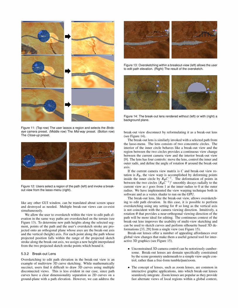
Figure 11: (Top row) The user lassos a region and selects the Birds-eye camera preset. (Middle row) The Mid-way preset. (Botton row)The Close-up preset.
Figure 12: Users select a region of the path (left) and invoke a break-out view from the lasso-menu (right).
like any other GUI window, can be translated about screen spaceand destroyed as needed. Multiple break-out views can co-existsimultaneously.
We allow the user to oversketch within the view to edit path el-evation in the same way paths are oversketched on the terrain (seeFigure 13). To determine new path heights along the selected seg-ment, points of the path and the user’s oversketch stroke are pro-jected onto an orthogonal plane whose axes are the break-out axisand the vertical (height) axis. For each point along the path whoseprojected position falls within the range of the projected sketchstroke along the break-out axis, we assign a new height interpolatedfrom the two projected sketch stroke points which bound it.
5.3.2 Break-out Lens
Oversketching to edit path elevation in the break-out view is anexample of multiview 3D curve sketching. While mathematicallysuccinct, users find it difficult to draw 3D curves using multipledisconnected views. This is less evident in our case, since pathcurves have a clear dimensionality separation as 2D curves on aground-plane with a path elevation. However, we can address the
Figure 13: Oversketching within a breakout-view (left) allows the userto edit path elevation. (Right) The result of the oversketch.
Figure 14: The break-out lens rendered without (left) or with (right) abackground plane.
break-out view disconnect by reformulating it as a break-out lens(see Figure 14).
The break-out lens is similarly invoked with a selected path fromthe lasso-menu. The lens consists of two concentric circles. Theinterior of the inner circle behaves like a break-out view and theregion between the two circles provides a continuous view changebetween the current camera view and the interior break-out view[9]. The lens has four controls: move the lens, control the inner andouter radii, and define the angle of rotation θ around the break-outaxis.
If the current camera view matrix is C and break-out view ro-tation is Rθ , the view warp is accomplished by deforming pointsinside the inner circle by RθC−1. The deformation of points inbetween the two circles (RθC−1)t smoothly decays radially to thecurrent view as t goes from 1 at the inner radius to 0 at the outerradius. We have implemented the view warping technique both insoftware and as a vertex shader to run on the GPU.
The break-out lens, like the break-out view, allows oversketch-ing to edit path elevation. In this case, it is possible to performoversketching using any setting for θ so long as the vertical axisis not coincident with the camera viewing direction. Intuitively, arotation θ that provides a near-orthogonal viewing direction of thepath will be more ideal for editing. The continuous context of thebreak-out lens improves the usability of multi-view sketching andcan be used to sketch curves and perform silhouette based 3D de-formations [33, 29] from a single view (see Figure 15).
Break-out lenses offer a number of appealing affordances overglobal view changes that make them a useful general tool for inter-active 3D graphics (see Figure 15).
• Unconstrained 3D camera control can be notoriously cumber-some. Break-out lenses are domain specifically constrainedby the scene geometry underneath to a simple view-angle con-trol, rather than a free-form tumble/pan/zoom.
• The concept of lenses, such as zoom lenses, are common ininteractive graphic applications, into which break-out lensesseamlessly integrate. Zoom lenses are popular as they providefast alternate views of local regions within a global context,

Figure 15: A curve is sketched and oversketched with a break-outlens to define a wire deformation of the nose.
Figure 16: The break-out view of a path (left) can be occluded byscene geometry in the foreground. The break-out lens (right) avoidsocclusion problems by deforming scene geometry locally.
while keeping user-focus on a primary task. Break-out lensessimilarly allow continued sketching in a desired view with lo-cal view changes when needed, instead of bookmarking theview, temporarily changing it and then jumping back.
• Oversketching in a break-out lens is natural for path heightediting and homogeneous with path editing on the terrain. Incontrast, the same oversketch after a global view change canbe ambiguously interpreted as a path height edit or a path editon the terrain.
• Tumbling a birds-eye view to the ground often causes hillyterrain to occlude the sketched path/region. Users may be ableto dolly the view-in past occluding features, or to manuallyadjust camera clip planes to solve this. Instead, the localityof the break-out lens solves this problem by design (see Fig-ure 16).
5.3.3 Rendering the Background Plane
A major difference between the break-out view in Figure 12 and thebreak-out lens in Figure 14 is the lack of a horizon and backgroundin the lens. This is because the terrain wraps around continuouslyobscuring the background plane. We can address this by render-ing a background plane on the far side of the path from the camerato simulate a horizon and background. This plane, drawn strictlywithin the inner radius, makes the view within the lens more like aview from ground perspective, yet provides a continuous transitionon the near side (see Figure 14). The opacity of the backgroundplane is interpolated with the rotation of the lens to produce a con-tinuous transition (the system uses values of 30 and 75 degrees tointerpolate from transparent to opaque).
6 TIMING AND PLAYBACK
Visualizing the navigation experience along paths is an essentialaspect of our system. Lassoing a path and selecting Play from thelasso-menu starts a vehicle navigating along it. The camera view
during playback can be selected from a context sensitive lasso-menu (see video) from a set of meaninigful predefined views orcontrolled by the user in a freeform manner. If the user select por-tions of paths with intersections, the straightest option is followed.Navigation speed is a constant by default. The user can alter thetiming along the path by selecting a region of the path and choos-ing a speed from the timing menu item (our system depicts thesetimings as speed limit signs placed roadside).
7 IMPLEMENTATION
Our path design system Drive is implemented in C + + usingOpenGL and GLUT. It was tested on 2 systems: an AMD Athlon643000+ 2GHz and an Intel Xeon 2.2GHz, both with 1 GB RAM.Many of the terrains demonstrated are represented as grids whoseresolutions range from 256x256 to 1024x1024. Path pieces andother environmental geometry primitives consist of approximately100-200 triangles each. Complex scenes authored with our systemconsisting of hundreds of thousands of triangles can be displayedand interacted with in real-time. All aspects of creation and render-ing in our system: sketching, clothoid fitting, path crossing resolu-tion, view warping and editing operations perform in real-time.
8 CONCLUSION
Our system was initially aimed at custom path design for virtualgame environments. Early conversations with practicing landscapearchitects, however, made us realize both the broader applicationspace of conceptual path design and the lack of any existing sys-tems that address it. We informally evaluated our system by pro-viding a brief set of instructions and the application to half a dozenpeople with mixed computer graphics skill. In general, the responsewas positive and the surprise bonuses of terrain sensitive geometrykept the users engaged. Some were able to discover most of thefunctionality without being told. We also revaluated our applica-tion with the landscape architects who felt the system was instantlyuseable in conceptual transportation layout. No comment was madeabout the lasso-menu which we see as a sign of a good inconspicu-ous UI. The feedback with respect to all our design goals was posi-tive, though some users familiar with CG applications, persistentlynavigated the scene with the 3D camera controls by habit.
In summary, we have presented a novel system for the conceptsketching of path layouts. Our system integrate a number of newideas each of which is also applicable to a wider range of ap-plications. Clothoid fitting is shown to be useful for generatingfair curves from input sketch strokes. Arbitrarily complex self-occluding 3D curves can be effectively created using our optimiza-tion of crossing relationships. The break-out view and lens finduse in general shape modeling and visualization (see Figure 15).The locality of the break-out lens in particular guarantees that anyregion can be seen from an arbitrary viewpoint without being ob-scured by other parts of the scene. Terrain sensitive sketching addsto the overall appeal of our system, allowing users to very quicklyauthor engaging environments. In the future, we hope to extendterrain sensitive sketching from curve layouts to area layouts withapplications in landscaping and urban planning.
REFERENCES
[1] A. Agarawala and R. Balakrishnan. Keepin’ it real: pushing the desk-top metaphor with physics, piles and the pen. In CHI ’06: Proceedingsof the SIGCHI conference on Human Factors in computing systems,pages 1283–1292. ACM, 2006.
[2] F. Anastacio, M. C. Sousa, F. Samavati, and J. A. Jorge. Modelingplant structures using concept sketches. In NPAR ’06: Proceedings ofthe 4th international symposium on Non-photorealistic animation andrendering, pages 105–113, New York, NY, USA, 2006. ACM.
[3] T. Baudel. A mark-based interaction paradigm for free-hand drawing.In Proceedings of UIST 1994, pages 185–192. ACM, 1994.

[4] E. A. Bier, M. C. Stone, K. Pier, K. Fishkin, T. Baudel, M. Conway,W. Buxton, and T. DeRose. Toolglass and magic lenses: the see-through interface. In CHI ’94: Conference companion on Humanfactors in computing systems, pages 445–446, New York, NY, USA,1994. ACM.
[5] N. Burtnyk, A. Khan, G. Fitzmaurice, R. Balakrishnan, and G. Kurten-bach. Stylecam: interactive stylized 3d navigation using integratedspatial & temporal controls. In UIST ’02: Proceedings of the 15thannual ACM symposium on User interface software and technology,pages 101–110. ACM, 2002.
[6] M. Carpendale. Viewing transformations: Perspective, distortion anddeformation. In SIGGRAPH03 Course Notes; Theory and Practice ofNon-Photorealistic Graphics: Algorithms, Methods, and ProductionSystems Presentation. ACM, 2003.
[7] G. Chen, G. Esch, P. Wonka, P. Mueller, and E. Zhang. Interactiveprocedural street modeling. ACM Trans. Graph., 27(3), 2008.
[8] J. M. Cohen, L. Markosian, R. C. Zeleznik, J. F. Hughes, andR. Barzel. An interface for sketching 3d curves. In I3D ’99: Pro-ceedings of the 1999 symposium on Interactive 3D graphics, pages17–21, New York, NY, USA, 1999. ACM.
[9] P. Coleman and K. Singh. Ryan: rendering your animation nonlinearlyprojected. In NPAR ’04: Proceedings of the 3rd international sympo-sium on Non-photorealistic animation and rendering, pages 129–156,New York, NY, USA, 2004. ACM.
[10] F. Cordier and H. Seo. Free-form sketching of self-occluding objects.IEEE Comput. Graph. Appl., 27(1):50–59, 2007.
[11] R. C. Davis, B. Colwell, and J. A. Landay. K-sketch: A ”kinetic”sketch pad for novice animators. In CHI ’08: Proceedings of theSIGCHI conference on Human Factors in computing systems. ACM,2008.
[12] J. A. Dennison and C. D. Johnson. Technical Illustration: Techniquesand Applications. Goodheart-Wilcox, 2003.
[13] G. Farin, G. Rein, N. Sapidis, and A. J. Worsey. Fairing cubic b-splinecurves. Comput. Aided Geom. Des., 4(1-2):91–103, 1987.
[14] T. Grossman, R. Balakrishnan, and K. Singh. An interface for creatingand manipulating curves using a high degree-of-freedom curve inputdevice. In CHI ’03: Proceedings of the SIGCHI conference on Humanfactors in computing systems, pages 185–192, New York, NY, USA,2003. ACM.
[15] L. Guiqing, L. Xianmin, and L. Hua. 3d discrete clothoid splines. InCGI ’01: Proceedings of the International Conference on ComputerGraphics, page 321, Washington, DC, USA, 2001. IEEE ComputerSociety.
[16] L. Halprin. Notebooks 1959–1971. The MIT Press, 1972.[17] T. Igarashi, R. Kadobayashi, K. Mase, and H. Tanaka. Path drawing
for 3d walkthrough. In ACM Symposium on User Interface Softwareand Technology, pages 173–174, 1998.
[18] T. Igarashi, S. Matsuoka, and H. Tanaka. Teddy: a sketching interfacefor 3d freeform design. In SIGGRAPH ’07: ACM SIGGRAPH 2007courses, page 21, New York, NY, USA, 2007. ACM.
[19] L. B. Kara, K. Shimada, and S. D. Marmalefsky. Calligraphic inter-faces: An evaluation of user experience with a sketch-based 3d mod-eling system. Comput. Graph., 31(4):580–597, 2007.
[20] O. Karpenko, J. F. Hughes, and R. Raskar. Epipolar methods formulti-view sketching . In Eurographics Workshop on Sketch-BasedInterfaces and Modeling, pages 167–173, Aug. 2004.
[21] A. Khan, B. Komalo, J. Stam, G. Fitzmaurice, and G. Kurtenbach.Hovercam: interactive 3d navigation for proximal object inspection.In I3D ’05: Proceedings of the 2005 symposium on Interactive 3Dgraphics and games, pages 73–80. ACM, 2005.
[22] R. A. Kilgore. Silk, java and object-oriented simulation. In WSC ’00:Proceedings of the 32nd conference on Winter simulation, pages 246–252, San Diego, CA, USA, 2000. Society for Computer SimulationInternational.
[23] B. B. Kimia, I. Frankel, and A.-M. Popescu. Euler spiral for shapecompletion. Int. J. Comput. Vision, 54(1-3):157–180, 2003.
[24] F. D. F. M. S. T. Carpendale, D. J. Cowperthwaite. Multi-scale view-ing. In ACM SIGGRAPH 96 Visual Proceedings: The art and interdis-ciplinary programs of SIGGRAPH ’96, pages 149–149. ACM Press,1996.
[25] J. McCrae and K. Singh. Sketching piecewise clothoid curves. InSketch-Based Interfaces and Modeling 2008, pages 1–8. EurographicsAssociation, 2008.
[26] D. Meek and D. Walton. Clothoid spline transition spirals. Mathemat-ics of Computation, 59(199):117–133, July 1992.
[27] M. Muller, B. Heidelberger, M. Teschner, and M. Gross. Meshless de-formations based on shape matching. ACM Trans. Graph., 24(3):471–478, 2005.
[28] G. Mullineux and S. T. Robinson. Fairing point sets using curvature.Comput. Aided Des., 39(1):27–34, 2007.
[29] A. Nealen, T. Igarashi, O. Sorkine, and M. Alexa. Fibermesh: de-signing freeform surfaces with 3d curves. In SIGGRAPH ’07: ACMSIGGRAPH 2007 papers, page 41, New York, NY, USA, 2007. ACM.
[30] V. Pratt. Direct least-squares fitting of algebraic surfaces. In SIG-GRAPH ’87: Proceedings of the 14th annual conference on Computergraphics and interactive techniques, pages 145–152, New York, NY,USA, 1987. ACM.
[31] R. Schmidt, B. Wyvill, M. C. Sousa, and J. A. Jorge. Shapeshop:sketch-based solid modeling with blobtrees. In SIGGRAPH ’07: ACMSIGGRAPH 2007 courses, page 43, New York, NY, USA, 2007. ACM.
[32] R. Schneider and L. Kobbelt. Discrete fairing of curves and surfacesbased on linear curvature distribution. In In Curve and Surface De-sign: Saint-Malo, pages 371–380. University Press, 1999.
[33] K. Singh and E. Fiume. Wires: a geometric deformation technique.In SIGGRAPH ’98: Proceedings of the 25th annual conference onComputer graphics and interactive techniques, pages 405–414, NewYork, NY, USA, 1998. ACM.
[34] D. S. Tan, G. G. Robertson, and M. Czerwinski. Exploring 3d nav-igation: combining speed-coupled flying with orbiting. In CHI ’01:Proceedings of the SIGCHI conference on Human factors in comput-ing systems, pages 418–425, New York, NY, USA, 2001. ACM.
[35] M. Thorne, D. Burke, and M. van de Panne. Motion doodles: aninterface for sketching character motion. In SIGGRAPH ’07: ACMSIGGRAPH 2007 courses, page 24, New York, NY, USA, 2007. ACM.
[36] S. Tsang, R. Balakrishnan, K. Singh, and A. Ranjan. A suggestiveinterface for image guided 3d sketching. In CHI ’04: Proceedingsof the SIGCHI conference on Human factors in computing systems,pages 591–598, New York, NY, USA, 2004. ACM.
[37] D. Walton and D. Meek. A controlled clothoid spline. Computers &Graphics 29, pages 353–363, 2005.
[38] C. Ware and S. Osborne. Exploration and virtual camera control invirtual three dimensional environments. SIGGRAPH Comput. Graph.,24(2):175–183, 1990.
[39] N. Watanabe, M. Washida, and T. Igarashi. Bubble clusters: an in-terface for manipulating spatial aggregation of graphical objects. InUIST ’07: Proceedings of the 20th annual ACM symposium on Userinterface software and technology, pages 173–182, New York, NY,USA, 2007. ACM.
[40] R. C. Zeleznik, K. P. Herndon, and J. F. Hughes. SKETCH: An inter-face for sketching 3D scenes. In H. Rushmeier, editor, SIGGRAPH 96Conference Proceedings, pages 163–170. Addison Wesley, 1996.