interpreting concept sketches - vecgvecg.cs.ucl.ac.uk/projects/smartgeometry/concept... ·...
TRANSCRIPT

Interpreting Concept Sketches
Tianjia Shao1,2 Wilmot Li3 Kun Zhou4 Weiwei Xu5 Baining Guo6 Niloy J. Mitra1
1Univ. College London 2Tsinghua Univ. 3Adobe 4Zhejiang Univ. 5Hangzhou Normal Univ. 6MSRA
animated transitionsglobal junction-graph
fixed
slide
slidehinge
slide
drawing 1 drawing 2
junction arrows
drawing 1 drawing 2
proxies 1 proxies 2
Figure 1: We present a system to interpret concept sketches. Starting from input sketches (drawings 1 and 2) and rough geometry proxies,we automatically extract consistent proxy correspondence across the views and a global junction-graph encoding inter-proxy connections.The user can then interactively change view and/or manipulate junctions (based on arrow handles), or browse through animated transitionsequences. The key observation is that consistent inter-part relations can be inferred even based on largely inconsistent geometry information.
Abstract
Concept sketches are popularly used by designers to convey poseand function of products. Understanding such sketches, however,requires special skills to form a mental 3D representation of theproduct geometry by linking parts across the different sketchesand imagining the intermediate object configurations. Hence, thesketches can remain inaccessible to many, especially non-designers.We present a system to facilitate easy interpretation and explo-ration of concept sketches. Starting from crudely specified incom-plete geometry, often inconsistent across the different views, wepropose a globally-coupled analysis to extract part correspondenceand inter-part junction information that best explain the differentsketch views. The user can then interactively explore the abstractedobject to gain better understanding of the product functions. Ourkey technical contribution is performing shape analysis without ac-cess to any coherent 3D geometric model by reasoning in the spaceof inter-part relations. We evaluate our system on various conceptsketches obtained from popular product design books and websites.
CR Categories: I.3.5 [Computer Graphics]: Three-DimensionalGraphics and Realism—Computational Geometry and Object Mod-eling
Keywords: concept sketch, product design, part relations, shapeanalysis, NPR
Links: DL PDF WEB VIDEO DATA CODE
1 Introduction
Creating concept sketches that show the form and function of poten-tial designs is an essential part of the product design process. Suchsketches typically represent the product from one or more view-points to convey important geometric features of the object and itsconstituent parts. Often, the function of a product involves movingor reconfigurable parts, and in this case, designers usually sketch allthe relevant part configurations (e.g., the collapsed and expandedstates of a folding chair). Concept sketches serve two primary pur-poses. Designers often gain a better understanding of the designspace for a product by considering how the geometry and func-tional behavior of its constituent parts can vary, and sketching can-didate designs can help reveal what types of variations are interest-ing or appropriate. More importantly, designers often use conceptsketches to communicate ideas to their collaborators (product en-gineers, marketers, other designers within the same creative team,etc.) as well as external clients. For example, designers at IDEOoften discuss ideas with clients on a weekly basis during a project,and concept sketches play an important role in such meetings.
However, interpreting the form and function of an object from staticconcept sketches can be difficult (see Figure 2). Constructing amental representation of the product geometry requires viewers tofirst understand the spatial relationships between the viewpointsof multiple sketches and then establish correspondences betweenparts across the views. This is especially difficult for products withmoving parts, where both the viewpoint and part configuration canchange between two sketches. Furthermore, since the relative po-sitions and orientations of parts can vary, viewers must interprethow parts are connected to each other and how they move between
Figure 2: Concept sketch illustrating stages of a lock mechanism.

configurations. While some designers may have enough experiencereading concept sketches to overcome these challenges, clients ofdesign firms, engineers, and marketers often find it difficult to un-derstand how a proposed design works from a set of sketches.
In this work, we present an interactive tool that helps designers cre-ate concept sketches that better convey the form and function of aproduct design. The input to our system is a concept sketch that in-cludes drawings of the product in different configurations, possiblyfrom multiple viewpoints. Using our tool, the designer then pro-vides a few annotations to indicate the approximate geometry andcontact relationships of important parts. Our system uses these an-notations to create geometric proxies (e.g., cuboids, cylinders, etc.)for the object parts, and based on the relative positions and orienta-tions of these proxies across all the sketches, we automatically infera simple functional model that explains how the object configura-tion changes between each pair of drawings. Our system leveragesthis model to generate animated transitions that help viewers under-stand how the viewpoint and part configuration change between anytwo sketches by showing the relevant part proxies smoothly movingfrom one drawing to the next (see Figure 1). Designers can also usethese transitions to create new sketches by scrubbing the animationto an intermediate pose, adjusting the viewpoint if necessary, andthen sketching over the proxies. Finally, designers can scribble andadd annotations in one sketch and have the system propagate thechanges to the other sketches.
A key challenge in analyzing concept sketches is that parts are of-ten drawn in a rough or incomplete manner, and their geometriesare typically not consistent across multiple drawings. This makesit difficult to apply many existing computer vision approaches thatassume images are projections of a single, fixed 3D representation(see Figure 3). One key insight of our work is that accurate, consis-tent part geometries are not necessary for producing a useful func-tional model of a product design from a set of concept sketches.Our analysis allows for variations in the size, shape, and orienta-tion of part proxies across the input sketches, and focus on com-puting a globally consistent set of functional relationships betweenparts. In particular, we solve for a set of part junctions (e.g., fixed,hinge, slide, etc.) that explains the configurations of proxies acrossall sketches and defines how the proxies move from one config-uration to another. This analysis also establishes correspondencesbetween proxies across all the drawings.
The main contribution of this work is in demonstrating how we caninstrument concept sketches with simple functional models to betterconvey important characteristics of product designs. We introduceappropriate geometric analysis techniques that automate this “rig-ging” process these functional models. In the examples presentedin the paper, while is possible to manually rig the full motion, ourgoal is to automate the process. We demonstrate our system usinga variety of concept sketches from product design books and web-sites. Initial feedback from professional designers indicates that oursystem simplifies the process of conveying and interpreting conceptsketches, especially their functionality in terms of part movements.
Contributions. In summary, our main contributions include:
• an interactive system to facilitate interpretation of conceptsketches of man-made objects;
• recovering relations and degrees of freedom of object partsfrom rough and inconsistent initial geometry; and
• introducing tools to help create variations of existing conceptsketches by providing proxy-based context information, with-out requiring to commit to specific geometric details.
as seen fromcamera(A) a
a
drawing A drawing B
Figure 3: Input drawings (top) being sketches rather than actualphotographs of physical objects can have very different geometries.Based on user annotations we recover proxy geometry and cam-era models for the respective drawings. (Bottom-left) We observea large discrepancy of size when both proxy sets are seen from thesame camera; (bottom-right) even in the same view, part ratios candiffer — making direct geometry-based shape analysis challenging.
2 Related Work
Shape analysis. In geometric shape analysis, different methodshave been proposed in the context of manmade objects, includingsymmetry detection [Mitra et al. 2012]; etc. The extracted informa-tion can then be used for intuitive model manipulation and creation.For example, manipulating man-made objects [Gal et al. 2009];joint-aware deformations of humanoid objects [Xu et al. 2009];or structure-aware manipulation in general [Mitra et al. 2013a]. Intwo related efforts, Mitra et al. [2013b] perform motion analysis ofpolygonal models of mechanical assemblies to understand and vi-sualize how the assemblies work; while Zhu et al. [2011] analyze2.5D sketches and perform hydraulic simulation to allow users tointeractively edit and illustrate fluid flows.
Our goal is also to understand modes of working of man-made mod-els. However, we neither have access to any consistent 3D geome-try, nor can we rely on the accuracy of the sketches. Hence, thechallenge is to robustly infer geometric relations with access to onlysparse, imprecise, and possibly inconsistent input.
Thinking with sketches. Suwa and Tversky [2009] investigate howdesigners first consider general object configurations before com-mitting to particular shape of geometries. They discuss the impor-tance of extending sketches in time and space (i.e., in our context,changes in viewpoint and changes in object configurations) to betterconvey temporal events. Further, sketches are essential to commu-nicate ideas and collaborate with others [Heiser et al. 2004]. How-ever, for such a work-mode to be successful, sketches should beeasy to understand and interpret across people with different skillsand background (e.g., designer, engineers, clients).
Cuboid based scene understanding. In the context of man-madeenvironments, researchers have demonstrated use of 3D cuboids forscene understanding from single images. This has led to interestingapplication in context-aware recognition and image-based model-ing in computer vision and object-level image editing ([Gupta et al.2011] and references therein). In order to improve fitting accuracy,Fidler et al. [2012] learn a statistical deformable cuboid model toimprove precision. Zheng et al. [2012] propose an interactive algo-rithm for cuboid-based image understanding for indoor scene im-ages via joint image- and screen-space optimization.
globaljunction graph
ab
c
C
B A
A
C
B
exploration
userinteraction
establish partcorrespondence
infer consistentjunctions
computemotion paths
hinge
slide
drawing 1
drawing 2
proxies 1
proxies 2
contactgraph 1
contactgraph 2
analysis
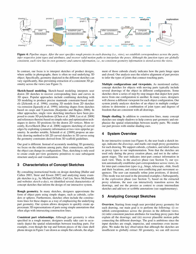
Figure 4: Pipeline stages. After the user specifies rough proxies in each drawing (i.e., view), we establish correspondence across the parts,infer respective joint types and attributes, and recover valid motion paths to interpolate the poses. Although the junction types are globallyconsistent, each view has its own geometry and camera information, i.e., no consistent geometry information is stored across the views.
In contrast, our focus is to interpret sketches of product designs,where unlike in photographs, there is often no real underlying 3Dobject. Specifically, geometry depicted in the different sketches canvary significantly, thus preventing extraction of a consistent 3D ge-ometry across the views (see Figure 3).
Sketch-based modeling. Sketch-based modeling interprets userdrawn 2D sketches to recover corresponding lines and curves in3D space. Popular approaches include combining sketching with3D modeling to produce precise manmade constraint-based mod-els [Zeleznik et al. 1996]; creating 3D models from 2D sketchesvia extrusion [Igarashi et al. 1999]; inferring shapes from sketchesbased on cusps and T-junctions [Karpenko and Hughes 2006]. Inother approaches, single view sketching interfaces have been pro-posed to create 3D polyhedrons ([Chen et al. 2008; Lee et al. 2008]and references therein) based on simple rules and optimization tech-niques to derive 3D positions for the drawn 2D vertices. More re-cently, ILoveSketch [Bae et al. 2008] supports sketching of curvededges by exploiting symmetry information or two-view epipolar ge-ometry. In another notable, Schmidt et al. [2009] propose an ana-lytic drawing method to lift 2D curved sketches to 3D curves usingthe geometry constraints derived from 3D scaffold guidelines.
Our goal is different. Instead of accurately modeling 3D geometry,we focus on the relations among parts, their connections, and howthe object can change its configuration. Thus, sketching is only usedto create crude per-view geometric primitives to ease subsequentstructure analysis and visualization.
3 Characteristics of Concept Sketches
By consulting instructional books on design sketching [Haller andCullen 2003; Steur and Eissen 2007] and analyzing many exam-ple sketches (e.g., by Michael DiTullo, Carl Liu, Steve McDonald;and websites sketch-a-day), we identified several characteristics ofconcept sketches that inform the design of our interactive system.
Rough geometry. In many sketches, designers approximate theform of object parts using simple shapes, such as cuboids, cylin-ders or spheres. Furthermore, sketches often include the construc-tions lines for these shapes as a way of emphasizing the underlyingpart geometry. Our system allows designers to quickly create ap-proximate 3D representations of parts using simple annotations thatoften align with intersecting construction lines.
Consistent part relationships. Although part geometry is oftenspecified in a rough manner, designers usually take care to accu-rately depict the spatial relationships between touching parts. Forexample, even though the top and bottom pieces of the clam shellphone design in Figure 3 are drawn as simple flat cuboids, the align-
ment of those cuboids clearly indicates how the parts hinge openand closed. Our analysis uses the relative alignment of part proxiesto infer the types of joints that connect touching parts.
Multiple configurations and viewpoints. As mentioned earlier,concept sketches for objects with moving parts typically includeseveral drawings of the object in different configurations. Somesketches show a series of step-by-step images that depict how partsmove from one configuration to another. In many cases, designerswill choose a different viewpoint for each object configuration. Oursystem jointly analyzes sketches of an object in multiple configu-rations to determine a combination of joint types and degrees offreedom that are consistent with all drawings.
Simple shading. In addition to construction lines, many conceptsketches use simple shadows to help convey part geometry and em-phasize the spatial relationships between nearby parts. We renderour part proxies with similar shading cues.
4 System Overview
In our interactive system (see Figure 4), the user loads a sketch im-age, indicates the drawings, and marks out rough proxy geometriesfor each drawing. We support cuboids, cylinders, and ruled surfacesas proxy types in our implementation. Note that the sketches areused only during the proxy creation phase, and not in the subse-quent stages. The user indicates inter-part contact information ineach view. Then, in the analysis phase (see Section 5), our sys-tem automatically establishes part correspondence across views, in-fer inter-part connection types (e.g., hinge, telescopic, slide, fixed)and their locations, and extract non-conflicting part movement se-quences. The user can manually refine joint positions, if desired.(This mode was not used in the presented examples.) Subsequently,in the exploration phase (see Section 7), based on the extractedproxy relations, the user can interactively transition across thedrawings, and use the proxies as context to create intermediatesketches and add text or scribble annotations (see supplementary).
5 Analyzing Concept Sketches
Overview. Starting from rough user provided proxy geometry foreach drawing, our main goal is to perform the following: (i) es-tablish correspondence across the proxies in the different views;(ii) infer consistent junction attributes for touching proxy pairs thatexplain all the drawings; and (iii) recover plausible motion pathsconnecting the different drawings. The goal is ambitious since theinput sketches are rough, imprecise, and sometimes even incom-plete. We make the key observation that although the sketches areinsufficient to globally extract 3D geometry, we can still recover
d
f
a
bc
(a,d)(a,e)(a,f)
(b,d)(b,e)(b,f)(c,d)(c,e)(c,f)
(a,d
)(a
,e)
(a,f)
(b,d
)(b
,e)
(b,f)
(c,d
)(c
,e)
(c,f)
.08 .610 000 0 0 .61
0 0.01 .33.630 0 0 0
0 00 00.18 0 0 0
0 0.63 0.0030 0 .20 0
.61 .0020 000 .52 0 1
0 0.33 .00500 0 0 0
0 .520 000 0 0 0
0 00 0.200 0 0 0
.61 10 000 0 0 .0001
e
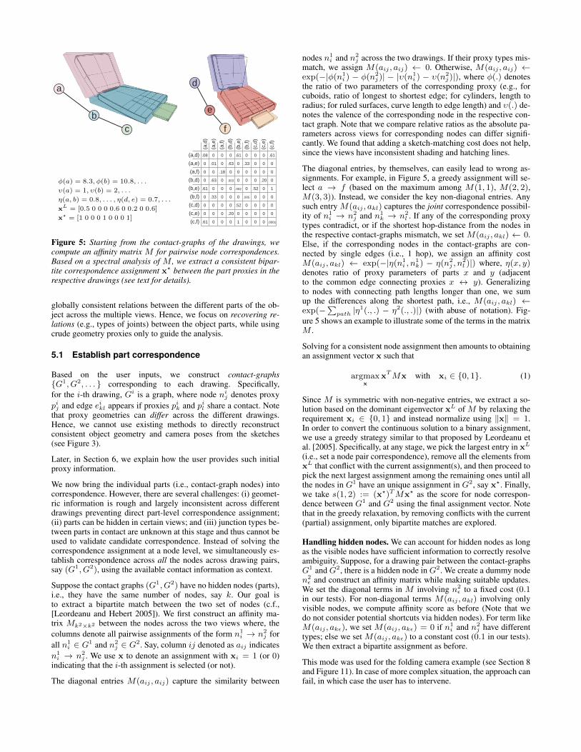
φ(a) = 8.3, φ(b) = 10.8, . . .
υ(a) = 1, υ(b) = 2, . . .
η(a, b) = 0.8, . . . , η(d, e) = 0.7, . . .
xL = [0.5 0 0 0 0.6 0 0.2 0 0.6]
x? = [1 0 0 0 1 0 0 0 1]
Figure 5: Starting from the contact-graphs of the drawings, wecompute an affinity matrix M for pairwise node correspondences.Based on a spectral analysis of M , we extract a consistent bipar-tite correspondence assignment x? between the part proxies in therespective drawings (see text for details).
globally consistent relations between the different parts of the ob-ject across the multiple views. Hence, we focus on recovering re-lations (e.g., types of joints) between the object parts, while usingcrude geometry proxies only to guide the analysis.
5.1 Establish part correspondence
Based on the user inputs, we construct contact-graphs{G1, G2, . . . } corresponding to each drawing. Specifically,for the i-th drawing, Gi is a graph, where node nij denotes proxypij and edge eikl appears if proxies pik and pil share a contact. Notethat proxy geometries can differ across the different drawings.Hence, we cannot use existing methods to directly reconstructconsistent object geometry and camera poses from the sketches(see Figure 3).
Later, in Section 6, we explain how the user provides such initialproxy information.
We now bring the individual parts (i.e., contact-graph nodes) intocorrespondence. However, there are several challenges: (i) geomet-ric information is rough and largely inconsistent across differentdrawings preventing direct part-level correspondence assignment;(ii) parts can be hidden in certain views; and (iii) junction types be-tween parts in contact are unknown at this stage and thus cannot beused to validate candidate correspondence. Instead of solving thecorrespondence assignment at a node level, we simultaneously es-tablish correspondence across all the nodes across drawing pairs,say (G1, G2), using the available contact information as context.
Suppose the contact graphs (G1, G2) have no hidden nodes (parts),i.e., they have the same number of nodes, say k. Our goal isto extract a bipartite match between the two set of nodes (c.f.,[Leordeanu and Hebert 2005]). We first construct an affinity ma-trix Mk2×k2 between the nodes across the two views where, thecolumns denote all pairwise assignments of the form n1
i → n2j for
all n1i ∈ G1 and n2
j ∈ G2. Say, column ij denoted as aij indicatesn1i → n2
j . We use x to denote an assignment with xi = 1 (or 0)indicating that the i-th assignment is selected (or not).
The diagonal entries M(aij , aij) capture the similarity between
nodes n1i and n2
j across the two drawings. If their proxy types mis-match, we assign M(aij , aij) ← 0. Otherwise, M(aij , aij) ←exp(−|φ(n1
i ) − φ(n2j )| − |υ(n1
i ) − υ(n2j )|), where φ(.) denotes
the ratio of two parameters of the corresponding proxy (e.g., forcuboids, ratio of longest to shortest edge; for cylinders, length toradius; for ruled surfaces, curve length to edge length) and υ(.) de-notes the valence of the corresponding node in the respective con-tact graph. Note that we compare relative ratios as the absolute pa-rameters across views for corresponding nodes can differ signifi-cantly. We found that adding a sketch-matching cost does not help,since the views have inconsistent shading and hatching lines.
The diagonal entries, by themselves, can easily lead to wrong as-signments. For example, in Figure 5, a greedy assignment will se-lect a → f (based on the maximum among M(1, 1), M(2, 2),M(3, 3)). Instead, we consider the key non-diagonal entries. Anysuch entry M(aij , akl) captures the joint correspondence possibil-ity of n1
i → n2j and n1
k → n2l . If any of the corresponding proxy
types contradict, or if the shortest hop-distance from the nodes inthe respective contact-graphs mismatch, we set M(aij , akl) ← 0.Else, if the corresponding nodes in the contact-graphs are con-nected by single edges (i.e., 1 hop), we assign an affinity costM(aij , akl) ← exp(−|η(n1
i , n1k) − η(n2
j , n2l )|) where, η(x, y)
denotes ratio of proxy parameters of parts x and y (adjacentto the common edge connecting proxies x ↔ y). Generalizingto nodes with connecting path lengths longer than one, we sumup the differences along the shortest path, i.e., M(aij , akl) ←exp(−
∑path |η
1(., .) − η2(., .)|) (with abuse of notation). Fig-ure 5 shows an example to illustrate some of the terms in the matrixM .
Solving for a consistent node assignment then amounts to obtainingan assignment vector x such that
argmaxx
xTMx with xi ∈ {0, 1}. (1)
Since M is symmetric with non-negative entries, we extract a so-lution based on the dominant eigenvector xL of M by relaxing therequirement xi ∈ {0, 1} and instead normalize using ‖x‖ = 1.In order to convert the continuous solution to a binary assignment,we use a greedy strategy similar to that proposed by Leordeanu etal. [2005]. Specifically, at any stage, we pick the largest entry in xL
(i.e., set a node pair correspondence), remove all the elements fromxL that conflict with the current assignment(s), and then proceed topick the next largest assignment among the remaining ones until allthe nodes in G1 have an unique assignment in G2, say x?. Finally,we take s(1, 2) := (x?)TMx? as the score for node correspon-dence between G1 and G2 using the final assignment vector. Notethat in the greedy relaxation, by removing conflicts with the current(partial) assignment, only bipartite matches are explored.
Handling hidden nodes. We can account for hidden nodes as longas the visible nodes have sufficient information to correctly resolveambiguity. Suppose, for a drawing pair between the contact-graphsG1 and G2, there is a hidden node in G2. We create a dummy noden2ε and construct an affinity matrix while making suitable updates.
We set the diagonal terms in M involving n2ε to a fixed cost (0.1
in our tests). For non-diagonal terms M(aij , akl) involving onlyvisible nodes, we compute affinity score as before (Note that wedo not consider potential shortcuts via hidden nodes). For term likeM(aij , akε), we set M(aij , akε) = 0 if n1
i and n2j have different
types; else we set M(aij , akε) to a constant cost (0.1 in our tests).We then extract a bipartite assignment as before.
This mode was used for the folding camera example (see Section 8and Figure 11). In case of more complex situation, the approach canfail, in which case the user has to intervene.

Building a global graph. We compute the pairwise contact-graphnode correspondence for all the pairs (Gi, Gj) along with their as-signment scores s(i, j). We construct a meta-graph with the graphsGi as nodes and exp(−s(i, j)) as edge costs to extract a consistentnode assignment across the different views using its minimum span-ning tree. A global contact-graph G? is created where each groupof corresponding nodes across the drawing gets assigned as a node.We add contact edges between any two nodes if a correspondingedge exists in any of the original contact-graphs.
5.2 Infer consistent junctions
Having extracted the global contact-graph, in a key stage, we assignjunction type for each of the contact edges that best explains all thedrawings. We handle the following commonly occurring junctiontypes in our system (see Figure 6): fixed, hinge, slide (or telescopic)where each type has at most one degree-of-freedom (DOF). Specif-ically, fixed junction has no DOF; hinge has only one DOF aboutthe axis of rotation; and slide also has only one DOF in the direc-tion of sliding. Further, we observe that the axis of rotation or slid-ing is commonly related to symmetry information of the underlyingproxies, e.g., plane of reflection for cuboids, or axis of rotation forcylinders (see also [Mitra et al. 2013b]). Note that if the same junc-tion is explained equally well by a fixed joint and any other junctiontype, we give priority to the fixed joint.
fixed hinge
telescopic channel
slide
Figure 6: Different types of junction types handled by our system.Fixed has no degree of freedom (DOF), while each of the others has1 DOF. Telescopic and channel are both instances of slide jointsand depend on the corresponding primitives types (i.e., cuboid vs.cylinder). If case of a tie, we give preference to fixed joints.
A simple solution to determine junction types can be: for each pairof proxies in contact (i.e., edge in the global graph), we find dif-ferent poses (i.e., views or drawings) with the known correspon-dence of the respective nodes and find the junction type that bestexplains all the views. However, there are challenges that makessuch a greedy assignment unsuitable: (i) proxy and camera infor-mation in each view are only approximate resulting in even correctjunction assignment getting a poor alignment score; and (ii) nodesand/or junctions can be hidden (hence corresponding junction edgeinformation will be missing) resulting in no direct information forthe corresponding contacts.
Our main observation is the following: Suppose proxies Pa, Pb, andPc share contact such that Pa is in contact with Pb; Pb is in con-tact with Pc; but Pa and Pc are not in direct contact. Now, even if(junction of) Pb is hidden or missing in any drawing, informationabout the relative pose of Pa and Pc still provide valuable informa-tion about both joints Pa ↔ Pb and Pb ↔ Pc. In other words, evenif proxy Pb is missing, we can jointly reason about the invisiblejoints Pa ↔ Pb and Pb ↔ Pc based on the visible poses of Pa andPc. Hence, we assign the junction types using a globally-coupledformulation.
Based on the extracted global contact-graph, we first build a multi-connection graph (see Figure 7) by explicitly listing all the typesof connection edges. Specifically, we replace each contact edgeeij ∈ G? by a set of connection edges explicitly denoting all types
a
b
c
20.8
0
0
fixedhingeslide
1.27
20.8
.01
.01
.01
20.9
20.9
20.9
20.9 20.9 20.9
1.28 1.28 1.28
1.28
1.28
1.28
20.9
20.9
20.9
20.9 20.9 20.9
0 0
00
0 0
00
0
0
0
0
00
0
0
0
0
.005
.005
.004
7.65
global contactgraph
multi-connection
graph
detected junctions
RO
UN
D 1
RO
UN
D 2
χ1ab
χ2ab
χ3ab
χ1bc
χ2bc
χ3bc
H
χ1ab
χ2ab
χ3ab
χ1bc
χ2bc
χ3bc
χ1abχ
2abχ
3abχ
1bcχ
2bcχ
3bc
y? = [0 1 0 0.33 0.33 0.35]
y? = [0.49 0 .50]
H
χ1bc
χ2bc
χ3bc
χ1bc χ
2bc χ
3bc
f =
Figure 7: Starting from the extracted node correspondence and theglobal-contact graph, we formulate a quadratic program to extracta consistent set of junctions to explain all the drawings (see Fig-ure 5). The assignments happen in rounds, with y? showing the tworounds in this example. See text for details.
of junction edges as eij → {e1ij , . . . ekij} where, for example, e1ijdenotes fixed junction, e2ij denotes hinge junction, etc. We assignindicator variables of the form χkij ∈ {0, 1} to denote if the edgetype ekij gets selected (χkij = 1) or not (χkij = 0). Since we expectany contact to have a unique junction type, we require∑
k
χkij = 1 ∀eij ∈ G?. (2)
Now, suppose E(χkij) denotes the penalty of eij being classified asthe k-th type junction; and E(χkij , χ
lpq) denotes the penalty of eij
being classified as the k-th type junction AND epq being classifiedas the l-th type junction. (Later, we elaborate these terms.) Thus ourproblem amounts to finding assignments such that:
argmin{χkij}
∑k,eij∈G?
E(χkij) +∑
k,l;eij ,ejq∈G?E(χkij , χ
ljq) (3)
subject to the linear constraints in Equation 2. We first explain thepenalty terms.
Penalty terms. We calculate single edge penalty term E(χkij) be-tween two proxies Pi and Pj sharing a direct contact (i.e., by eij).Since Pi and Pj appear across multiple views, we choose to com-pute the single edge term by aligning the relative orientation andposition of Pi to Pj across all drawings (i.e., views) according toits junction type assignment (i.e., fixed, hinge, etc.). For example,with k = 2 we test how well a hinge joint explains the relative poseof Pi and Pj across all the drawings by optimizing over the 1DOFhinge movement. We formulate this as:
E(χkij) := minµ
∑l
(‖Rl(µ)−R0‖2 + ‖tl(µ)− t0‖2
)(4)
where, R represents the relative orientation between Pi and Pj ,t represents the relative translation of the respective proxy center(normalized using available correspondence information), l iteratesover all the views containing Pi and Pj , and we arbitrarily fix one

view as the comparison basis (as view 0). The relative orientationis represented by a 3 × 3 matrix and its difference is calculated byFrobenius norm. The set of joint parameters µ varies for differentjoint types: for a hinge joint, its parameters contain the rotation axisand position; for a sliding joint, an axis and the slide parameter.Note that we assume that hinges are at proxy edges; while slidedirections are aligned to proxy symmetry planes. All the terms arecomputed in the coordinate system of the 0-th drawing. For eachjunction type assignment in the single edge term, we optimize theobjective function in Equation 4 as its final value.
The pair-edge penalty term E(χkij , χ
ljq) captures the penalty that
junction eij gets assigned type-k AND junction ejq gets assignedtype-l. If node Pj is visible in all views, we set E(χk
ij , χljq) ←
E(χkij) + E(χl
jq). If Pj is hidden but Pi and Pq are visible in anyl-th view, then we use inverse kinematics (IK) on the correspondingproxies in a view where all three are visible to guess the position ofPj in the l-th view using the visible Pi and Pk as the end effectors.Essentially, we use IK to ‘move’ the proxies across views to guessthe position of any missing proxy. If the end proxies (i.e., Pi or Pq)are invisible, we simply set the corresponding penalty term to zero.
Optimizing Equation 3 then amounts to
y� := argminy
1
2yTHy + fTy
s.t. y(i) ≥ 0 ∀i. (5)
subject to corresponding linear constraints in Equation 2 on y. Werelax the problem by allowing elements in y to take continuous val-ues and solve the minimization using quadratic programming (QP)to obtain y� (using Matlab quadprog function). Note that in the firstround f = 0.
We convert the solution to a valid assignment as follows: The high-est component, i.e., argmaxi y
�(i) is selected and the conflictingentries from the assignment vector are removed. We then updatematrix H and f by setting the assigned element in y to 1, and thusreducing the size of y to the number of existing unknowns. We re-peat the process until all the junctions are assigned. For example, inFigure 7, first y�(2) gets selected, i.e., a hinge junction is assignedbetween the pink and blue proxies. Then, we fix junction ab result-ing in y ← [0 1 0 χ1
bc χ2bc χ3
bc] and update H and f as shown inthe figure. In practice, since the number of proxies is small, the QPapproximation can be replaced by an exhaustive enumeration of thepossible assignments for a more exact result.
The extracted global assignment can still have loops in the finalgraph (e.g., in the case of the folding camera in Figure 11). Wecompute minimal spanning tree (MST) of the final graph to breakany loops using the corresponding per-edge costs as edge weights.Thus, at the end of this stage, we have determined the type of eachjunction between different proxy pairs. Note that although eachdrawing has its own set of geometry parameters (i.e., proxy size)and camera, all the views have a consistent set of junction typesassigned to the corresponding proxy pairs.
Determine joint parameters. We already recover the junction loca-tions and the corresponding edges in the above formulation. Fur-ther, we obtain the junction parameters (e.g., rotation angle or mag-nitude for sliding) for each drawing, which are later used in themotion interpolation stage.
5.3 Compute motion paths
At this stage, we have global junction-graph G� with correspondingnodes identified in each view and consistent junction types (and re-spective parameters) identified across the different drawings. Given
d
θ
θ
dΓa
Γb
Γc
Γd
drawing 1 drawing 2
Figure 8: We sample the configuration space to compute collisionfree motion paths. In this figure, red points denote self-collision,while green denotes collision-free states. Since directly interpolat-ing junction parameters Γa → Γd goes through collision states(e.g., Γc), we interpolate a motion sequence using non-collidingstates as Γa → Γb → Γd.
any view pair, we look at the corresponding graphs Gi and Gj .We first test if linearly interpolating junction parameters (recall wehave only 1 DOF moving junctions), usually one junction at time, iscollision free. (We discretize the path in 10 steps.) Since the proxysizes are different across views, we also linearly interpolate their re-spective sizes for intermediate poses weighted by relative distancesfrom the end configurations. If we detect any collision, we furtherrefine the interpolation space as follows. We assume that CSG, ifany, have already been applied to the proxies (see Section 6).
Say, Γi and Γj denote the vector of junction parameters (e.g., ro-tation angles for hinge motion, distance traveled for sliding mo-tion) for view graphs Gi and Gj (number of dimensions of Γ isequal to the number of junctions). We discretize the space of inter-mediate junction parameters (using 10 steps only along the com-ponents where Γi and Γj differ) and test for intersections amongthe proxies for the intermediate configurations. We then mark theseconfiguration space points as colliding or not-colliding, and simplyselect a path (e.g., shortest path) in this configuration space goingthrough only non-colliding states. In order to detect collision (ornot), we use the approximate proxies. However, the proxies in dif-ferent drawings have different sizes, and hence for any configura-tion Γ we interpolate the proxy dimensions from the end positions(drawings) weighted by ‖Γi − Γ‖ and ‖Γj − Γ‖, respectively. Forexample, in Figure 8, the proxy geometry of Γb is interpolated fromΓa and Γd. We found this simple approximation along with basicmotion planning to work well in our examples.
6 User interaction
The user starts by indicating the different drawings. Then, foreach drawing, she over-sketches to provide rough proxy geome-tries (cuboids, cylinders, and ruled surfaces). For cuboids, the user
drawing 1
drawing 2
mode (i)
mode (ii)
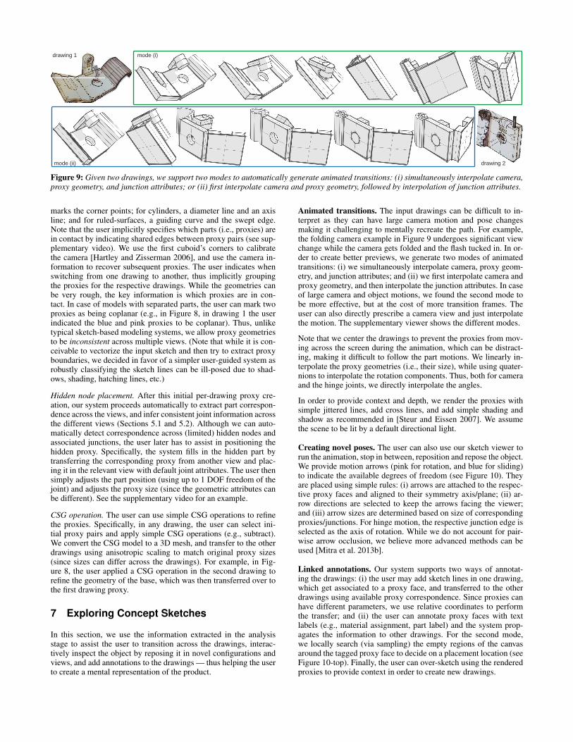
Figure 9: Given two drawings, we support two modes to automatically generate animated transitions: (i) simultaneously interpolate camera,proxy geometry, and junction attributes; or (ii) first interpolate camera and proxy geometry, followed by interpolation of junction attributes.
marks the corner points; for cylinders, a diameter line and an axisline; and for ruled-surfaces, a guiding curve and the swept edge.Note that the user implicitly specifies which parts (i.e., proxies) arein contact by indicating shared edges between proxy pairs (see sup-plementary video). We use the first cuboid’s corners to calibratethe camera [Hartley and Zisserman 2006], and use the camera in-formation to recover subsequent proxies. The user indicates whenswitching from one drawing to another, thus implicitly groupingthe proxies for the respective drawings. While the geometries canbe very rough, the key information is which proxies are in con-tact. In case of models with separated parts, the user can mark twoproxies as being coplanar (e.g., in Figure 8, in drawing 1 the userindicated the blue and pink proxies to be coplanar). Thus, unliketypical sketch-based modeling systems, we allow proxy geometriesto be inconsistent across multiple views. (Note that while it is con-ceivable to vectorize the input sketch and then try to extract proxyboundaries, we decided in favor of a simpler user-guided system asrobustly classifying the sketch lines can be ill-posed due to shad-ows, shading, hatching lines, etc.)
Hidden node placement. After this initial per-drawing proxy cre-ation, our system proceeds automatically to extract part correspon-dence across the views, and infer consistent joint information acrossthe different views (Sections 5.1 and 5.2). Although we can auto-matically detect correspondence across (limited) hidden nodes andassociated junctions, the user later has to assist in positioning thehidden proxy. Specifically, the system fills in the hidden part bytransferring the corresponding proxy from another view and plac-ing it in the relevant view with default joint attributes. The user thensimply adjusts the part position (using up to 1 DOF freedom of thejoint) and adjusts the proxy size (since the geometric attributes canbe different). See the supplementary video for an example.
CSG operation. The user can use simple CSG operations to refinethe proxies. Specifically, in any drawing, the user can select ini-tial proxy pairs and apply simple CSG operations (e.g., subtract).We convert the CSG model to a 3D mesh, and transfer to the otherdrawings using anisotropic scaling to match original proxy sizes(since sizes can differ across the drawings). For example, in Fig-ure 8, the user applied a CSG operation in the second drawing torefine the geometry of the base, which was then transferred over tothe first drawing proxy.
7 Exploring Concept Sketches
In this section, we use the information extracted in the analysisstage to assist the user to transition across the drawings, interac-tively inspect the object by reposing it in novel configurations andviews, and add annotations to the drawings — thus helping the userto create a mental representation of the product.
Animated transitions. The input drawings can be difficult to in-terpret as they can have large camera motion and pose changesmaking it challenging to mentally recreate the path. For example,the folding camera example in Figure 9 undergoes significant viewchange while the camera gets folded and the flash tucked in. In or-der to create better previews, we generate two modes of animatedtransitions: (i) we simultaneously interpolate camera, proxy geom-etry, and junction attributes; and (ii) we first interpolate camera andproxy geometry, and then interpolate the junction attributes. In caseof large camera and object motions, we found the second mode tobe more effective, but at the cost of more transition frames. Theuser can also directly prescribe a camera view and just interpolatethe motion. The supplementary viewer shows the different modes.
Note that we center the drawings to prevent the proxies from mov-ing across the screen during the animation, which can be distract-ing, making it difficult to follow the part motions. We linearly in-terpolate the proxy geometries (i.e., their size), while using quater-nions to interpolate the rotation components. Thus, both for cameraand the hinge joints, we directly interpolate the angles.
In order to provide context and depth, we render the proxies withsimple jittered lines, add cross lines, and add simple shading andshadow as recommended in [Steur and Eissen 2007]. We assumethe scene to be lit by a default directional light.
Creating novel poses. The user can also use our sketch viewer torun the animation, stop in between, reposition and repose the object.We provide motion arrows (pink for rotation, and blue for sliding)to indicate the available degrees of freedom (see Figure 10). Theyare placed using simple rules: (i) arrows are attached to the respec-tive proxy faces and aligned to their symmetry axis/plane; (ii) ar-row directions are selected to keep the arrows facing the viewer;and (iii) arrow sizes are determined based on size of correspondingproxies/junctions. For hinge motion, the respective junction edge isselected as the axis of rotation. While we do not account for pair-wise arrow occlusion, we believe more advanced methods can beused [Mitra et al. 2013b].
Linked annotations. Our system supports two ways of annotat-ing the drawings: (i) the user may add sketch lines in one drawing,which get associated to a proxy face, and transferred to the otherdrawings using available proxy correspondence. Since proxies canhave different parameters, we use relative coordinates to performthe transfer; and (ii) the user can annotate proxy faces with textlabels (e.g., material assignment, part label) and the system prop-agates the information to other drawings. For the second mode,we locally search (via sampling) the empty regions of the canvasaround the tagged proxy face to decide on a placement location (seeFigure 10-top). Finally, the user can over-sketch using the renderedproxies to provide context in order to create new drawings.

8 Results
We used our system to analyze concept sketches for eight differ-ent product designs (see Figure 11): a folding camera, cellphone,toolbox, printer, hairdryer, toaster oven, tablet, and lock. We askeda designer to create the cellphone and the tablet sketches, andthe remaining artworks come from various books on product de-sign [Olofsson and Sjolen 2005; Steur and Eissen 2007] and web-pages (e.g., Carl Liu’s sketches, sketch-a-day, etc.). The simplestsketch was the toaster oven, which included two drawings from(slightly) different viewpoints showing two parts connected by asingle joint in two different configurations. The most complicatedsketch was the folding camera, which had three drawings showingthe object in several different poses. The number of parts in thedesigns themselves ranges from two (hairdryer and toaster) to six(printer). For the cellphone, toolbox, tablet and lock, in the respec-tive first viewpoint, the user tagged two proxies as being coplanarsince they do not share any direct contact edge. In addition to anno-tating the sketches to create part proxies, we used CSG operationsto cut out the cavities for the camera lens and tablet base, etc. (seeTable 1 and supplementary video). We also specified the size andposition of one hidden proxy for the camera lens. No other user in-tervention was required to generate the functional models from theeight sketches.
Table 1: Statistics for the different examples.
model #drawings #parts #junctions user inter.folding camera 3 5 4 hidden/CSGcellphone 3 3 2 coplanartoolbox 2 3 2 coplanar/CSGprinter 3 6 5 CSGhairdryer 3 2 1 CSGtoaster oven 2 2 1 -tablet 2 3 2 coplanarlock 2 3 2 coplanar/CSG
For each sketch, we generated animated transitions between all ofthe individual subdrawings. Figure 11 shows snapshots from oneanimated transition for each product; for more transitions, pleaserefer to our supplemental video and/or the executable of our sketchviewer. The transitions help clarify the relationships in severalsketches. For example, Figure 11a makes it clear how the lens,screen, and flexible outer cover fold together as the camera col-lapses into its closed position. Furthermore, since the screen looksquite different in the two original sketches (we only see the yel-low face of the screen in the collapsed sketch), the transition alsohelps establish the correspondences between parts. Even for rela-tively simple objects like the cellphone in Figure 11b, it may notbe clear which end of the phone is closer to the camera (top or bot-tom?) in the final sketch. Here, the transition confirms that we arelooking at the bottom of the phone and that the black slit depictsthe memory card slot. For sketches with more moving parts, likethe printer (Figure 11d), our functional model conveys how differ-ent parts move. In this case, we can quickly see that the two papertrays at the bottom slide out from the main compartment, while thepanel at the back hinges open to allow access to paper jams.
To get some informal feedback on our system, we showed our in-teractive tool to three professional designers, including one currentand one former IDEO employee. All the designers felt that our ani-mated transitions would “facilitate communication” and help view-ers interpret sketches to better understand the functional charac-teristics of the depicted design. They also agreed that our visual-izations would likely be most useful for non-designers and non-engineers (e.g., marketers, clients). In terms of the authoring work-flow, the designers felt that the amount of work required to annotatesketches was very reasonable, especially compared to the time and
interactiveposingarrow handles
text annotations
Figure 10: In the exploration stage, our system supports: (i) cou-pled annotations, i.e., user marks in one drawing that then getstransferred and automatically placed based on the underlying proxycorrespondence; (ii) arrow handle based changing of part poses;and (iii) interactive view and pose changes.
effort required to create the original sketches. One designer said thatour authoring workflow seemed “a million times faster than doingthis [modeling] in SolidWorks,” which is what he sometimes doeswhen he wants to create a functional prototype to show others.
While the feedback was predominantly positive, there were a fewsuggestions for improvement as well. One designer wondered howeffective our proxies would be for representing objects with morecomplex or organic shapes. For such shapes, it is possible thatcuboids, cylinders and ruled surfaces could provide enough geo-metric information to convey the overall configuration of parts andhow they move, but it would be interesting to validate this hy-pothesis with perceptual experiments. Another designer questionedwhether the current system could be useful for creating functionalmodels from extremely rough sketches during the early, brainstorm-ing stages of the design process. Despite the fact that our annotationworkflow is already quite straightforward, it is likely still too muchoverhead for this use case (e.g., ideally, annotating a 10-secondsketch would take just a few additional seconds). Conducting per-ceptual experiments and further automating the annotation work-flow are both interesting areas for future work. Note that in ourcurrent formulation we only handle junctions with up to 1 DOF, butin the future we will like to explore more junction types (e.g., com-bination of hinge and slide). This will possibly require revisiting theformulation in Equation 3.
We will further like to discuss the following limitations: (i) In cer-tain situations, there can be insufficient information to assign anunique bipartite correspondence, but there can be multiple verycomparable assignments. For example, in the tablet example, therewas another assignment that got very close node correspondencescores, and just luckily the desired one was selected. In such sit-uations, we believe allowing the user to select among the top as-signment suggestions will be appropriate. (ii) By focusing on rela-tions, we demonstrated robustness to relatively large variations inproxy geometries, our algorithm does break down when the proxiesare very poor or the drawings are less structured (e.g., for napkinsketches). It remains unclear how such ambiguity can be tamed;.Finally, (iii) for complex models, as the part numbers increase lead-ing to more hidden parts, our method can fail due to the ambiguityarising from multiple hidden nodes.

(d) printer
(a) folding camera
(b) cellphone
(c) toolbox
(e) hairdryer(e) hairdryer
(d) printer(d) printer
(e) hairdryer(e) hairdryer
(f) toaster oven
(g) tablet
(h) lock
Figure 11: Animated transitions created automatically produces by our system to facilitate interpretation of the input concept sketches. Theinitial sketches are used only for guidance while specifying the initial proxies (indicated by colored boxes).
9 Conclusion and Future Work
We presented an interactive system to facilitate interpretation andexploration of concept sketches. Starting from rough user anno-tations on a set of drawings, our system builds a set of guidingproxy geometry, and then solves for a globally consistent joint as-signment that links the different drawings. We proposed a novelanalysis method to solve for such joint assignments by focusingmainly on inter-part relations, with geometry playing only a sec-ondary role. We also presented simple exploration options that usethe view specific geometry and camera information, linked by aglobal contact graph, and allows the user to interactively explorethe concept sketches, thus allowing her to better understand the ob-ject functions, rather than specifics of its geometric form.
There are several interesting future directions to explore:Constrained modeling. Man-made objects often have self-similarity and structures, with different parts coupled by non-localconstraints [Gal et al. 2009]. For example, in Figure 11a, the twocuboid proxies have similar length and breadth in drawing #2; butdo not satisfy the same constraints in the other drawing. In the fu-ture, we plan to explore how to link the drawings and also carry theconstraints across them. Different drawings, however, can imposepotentially conflicting constraints, thus preventing a direct adapta-tion of techniques from traditional constraint-based modeling.Sketch-to-fab. In this work, we focused on generating intermedi-ate sketches to facilitate interpretation of a product’s functionality.From the extracted consistent global junction-graph, we can possi-bly extract a coherent 3D geometric model that satisfies the junctiontypes, without necessarily matching the sketched drawings. Such afunctional 3D model can then be adapted by the engineer to pro-duce an easy to fabricate model (with joint types, part parameters,etc.), thus simplifying the transition to a prototype 3D model.Integrated sketching. In the future, we plan to directly integrateour analysis framework into a smart sketching system so that thedesigner can use the proxy geometries to correctly sketch perspec-tive views and part configurations, reminiscent of analytic drawingusing scaffolds [Schmidt et al. 2009].
Acknowledgement. We are grateful to Xiaolong Lou for his helpwith sketching; Chen Li for his help with the rendering; CristinaAmati for video voiceover; Bongjin Koo, Hung-Ku Chu, and TaoDu for their comments on the initial draft of the paper; and theanonymous reviewers for their suggestions. We are thankful to CarlLiu for the folding camera; Spencer Nugent for the toolbox andtoaster oven; and Danian Yang for the lock sketches. The projectwas partially supported by a China Scholarship Council Fund,Adobe, NSFC grants, 973 program of China, the Open Project Pro-gram of the State Key Lab of CAD & CG, and a Marie Curie CIG.
References
BAE, S.-H., BALAKRISHNAN, R., AND SINGH, K. 2008. ILoveS-ketch: as-natural-as-possible sketching system for creating 3Dcurve models. In UIST, 151–160.
CHEN, X., KANG, S. B., XU, Y.-Q., DORSEY, J., AND SHUM,H.-Y. 2008. Sketching reality: Realistic interpretation of archi-tectural designs. ACM TOG 27, 2, 11:1–11:15.
FIDLER, S., DICKINSON, S., AND URTASUN, R. 2012. 3d objectdetection and viewpoint estimation with a deformable 3d cuboidmodel. In NIPS, 620–628.
GAL, R., SORKINE, O., MITRA, N. J., AND COHEN-OR, D.2009. iwires: an analyze-and-edit approach to shape manipu-lation. 33:1–33:10.
GUPTA, A., SATKIN, S., EFROS, A. A., AND HEBERT, M. 2011.From 3D scene geometry to human workspace. In CVPR, 1961–1968.
HALLER, L., AND CULLEN, C. D. 2003. Design Secrets: Prod-ucts 1 and 2: 50 Real-Life Product Design Projects Uncovered.Rockport Publishers.
HARTLEY, A., AND ZISSERMAN, A. 2006. Multiple view geome-try in computer vision (2. Ed.). Cambridge University Press.
HEISER, J., TVERSKY, B., AND SILVERMAN, M. 2004. Sketchesfor and from collaboration. Sydney: Key Centre for Design.
IGARASHI, T., MATSUOKA, S., AND TANAKA, H. 1999. Teddy:a sketching interface for 3d freeform design. In Proc. of SIG-GRAPH, 409–416.
KARPENKO, O. A., AND HUGHES, J. F. 2006. SmoothSketch:3D free-form shapes from complex sketches. Proc. ACM SIG-GRAPH 25, 3.
LEE, S., FENG, D., AND GOOCH, B. 2008. Automatic construc-tion of 3D models from architectural line drawings. In Proc. I3D,123–130.
LEORDEANU, M., AND HEBERT, M. 2005. A spectral tech-nique for correspondence problems using pairwise constraints.In ICCV, 1482–1489.
MITRA, N. J., PAULY, M., WAND, M., AND CEYLAN, D. 2012.Symmetry in 3D geometry: Extraction and applications. In EU-ROGRAPHICS State-of-the-art Report.
MITRA, N. J., WAND, M., ZHANG, H., COHEN-OR, D., ANDBOKELOH, M. 2013. Structure-aware shape processing. InEUROGRAPHICS State-of-the-art Report.
MITRA, N. J., YANG, Y.-L., YAN, D.-M., LI, W., ANDAGRAWALA, M. 2013. Illustrating how mechanical assemblieswork. Comm. of the ACM (Research Highlight) 56, 1, 106–114.
OLOFSSON, E., AND SJOLEN, K. 2005. Design Sketching. KeeosDesign Books.
SCHMIDT, R., KHAN, A., SINGH, K., AND KURTENBACH, G.2009. Analytic drawing of 3D scaffolds. ACM TOG (SIG-GRAPH Asia) 28, 5, 149:1–149:10.
STEUR, R., AND EISSEN, K. 2007. Sketching: Drawing techniquesfor product designers. BIS Publishers.
SUWA, M., AND TVERSKY, B. 2009. Thinking with sketches.Oxford University Press.
XU, W., WANG, J., YIN, K., ZHOU, K., VAN DE PANNE, M.,CHEN, F., AND GUO, B. 2009. Joint-aware manipulation ofdeformable models. Proc. ACM SIGGRAPH 28, 3, 35:1–35:9.
ZELEZNIK, R. C., HERNDON, K. P., AND HUGHES, J. F. 1996.SKETCH: an interface for sketching 3D scenes. In Proc. ACMSIGGRAPH.
ZHENG, Y., CHEN, X., CHENG, M.-M., ZHOU, K., HU, S.-M.,AND MITRA, N. J. 2012. Interactive images: cuboid proxies forsmart image manipulation. 99:1–99:11.
ZHU, B., IWATA, M., HARAGUCHI, R., ASHIHARA, T.,UMETANI, N., IGARASHI, T., AND NAKAZAWA, K. 2011.Sketch-based dynamic illustration of fluid systems. In ACM TOG(SIGGRAPH Asia), 134:1–134:8.