sjzl20083203-zxg10 ibsc (v6.20) technical manual
DESCRIPTION
ZTE ZXCi10 BSCTRANSCRIPT

ZXG10 iBSCBase Station Controller
Technical Manual
Version 6.20
ZTE CORPORATION ZTE Plaza, Keji Road South, Hi-Tech Industrial Park, Nanshan District, Shenzhen, P. R. China 518057 Tel: (86) 755 26771900 800-9830-9830 Fax: (86) 755 26772236 URL: http://support.zte.com.cn E-mail: [email protected]
LEGAL INFORMATION Copyright © 2006 ZTE CORPORATION. The contents of this document are protected by copyright laws and international treaties. Any reproduction or distribution of this document or any portion of this document, in any form by any means, without the prior written consent of ZTE CORPORATION is prohibited. Additionally, the contents of this document are protected by contractual confidentiality obligations. All company, brand and product names are trade or service marks, or registered trade or service marks, of ZTE CORPORATION or of their respective owners. This document is provided “as is”, and all express, implied, or statutory warranties, representations or conditions are disclaimed, including without limitation any implied warranty of merchantability, fitness for a particular purpose, title or non-infringement. ZTE CORPORATION and its licensors shall not be liable for damages resulting from the use of or reliance on the information contained herein. ZTE CORPORATION or its licensors may have current or pending intellectual property rights or applications covering the subject matter of this document. Except as expressly provided in any written license between ZTE CORPORATION and its licensee, the user of this document shall not acquire any license to the subject matter herein. ZTE CORPORATION reserves the right to upgrade or make technical change to this product without further notice. Users may visit ZTE technical support website http://ensupport.zte.com.cn to inquire related information. The ultimate right to interpret this product resides in ZTE CORPORATION.
Revision History
Date Revision No. Serial No. Reason for Revision
Oct 30, 2008 R1.0 sjzl20083203 First edition

ZTE CORPORATION Values Your Comments & Suggestions! Your opinion is of great value and will help us improve the quality of our product documentation and offer better services to our customers.
Please fax to: (86) 755-26772236; or mail to Technical Delivery Department, ZTE University, Dameisha, Yantian District, Shenzhen, Guangdong, P.R. China 518083.
Thank you for your cooperation!
Document Name ZXG10 iBSC (V6.20) Base Station Controller Technical Manual
Product Version V6.20 Document Revision Number R1.0
Serial No. sjzl20083203 Equipment Installation Date
Presentation: (Introductions, Procedures, Illustrations, Completeness, Level of Detail, Organization, Appearance)
Good Fair Average Poor Bad N/A
Accessibility: (Contents, Index, Headings, Numbering, Glossary)
Good Fair Average Poor Bad N/A
Your evaluation of this documentation
Intelligibility: (Language, Vocabulary, Readability & Clarity, Technical Accuracy, Content)
Good Fair Average Poor Bad N/A
Your suggestions for improvement of this documentation
Please check the suggestions which you feel can improve this documentation: Improve the overview/introduction Make it more concise/brief
Improve the Contents Add more step-by-step procedures/tutorials
Improve the organization Add more troubleshooting information
Include more figures Make it less technical
Add more examples Add more/better quick reference aids
Add more detail Improve the index
Other suggestions
__________________________________________________________________________
__________________________________________________________________________
__________________________________________________________________________
__________________________________________________________________________
__________________________________________________________________________
# Please feel free to write any comments on an attached sheet.
If you wish to be contacted regarding your comments, please complete the following:
Name Company
Postcode Address
Telephone E-mail

This page is intentionally blank.

Contents
About this Manual............................................................. i
Purpose................................................................................ i Intended Audience ................................................................. i Prerequisite Skill and Knowledge .............................................. i What is in This Manual............................................................ i Related Documentation.......................................................... ii Conventions........................................................................ iii How to Get in Touch............................................................. iv
Declaration of RoHS Compliance..................................... v
Chapter 1.......................................................................... 1
System Overview............................................................. 1
System Background ..............................................................1 Position of iBSC in Network ....................................................1 iBSC Appearance ..................................................................3 System Functions .................................................................5 System Features................................................................. 13 Standards Complied ............................................................ 14
Chapter 2........................................................................17
System Indices ..............................................................17
Physical Indices .................................................................. 17 Power Supply Indices .......................................................... 18 Environmental Conditions..................................................... 19 Clock Indices...................................................................... 20 Reliability Indices................................................................ 20 Interface Types .................................................................. 20 Capacity Indices ................................................................. 21
Chapter 3........................................................................23
System Architecture ......................................................23
System Composition ............................................................23 Hardware System................................................................23 Shelves..............................................................................25 Boards...............................................................................25 Software System.................................................................28
Chapter 4........................................................................31
Interfaces and Protocols ...............................................31
External Interfaces........................................................ 31
A-Interface.........................................................................33 Ater Interface (TC is External)...............................................33 Abis Interface .....................................................................34 Gb Interface .......................................................................34 OMC Interface ....................................................................34
Protocols ..................................................................... 35
Protocols in CS domain ........................................................35 Protocols in PS Domain ........................................................42
Chapter 5........................................................................47
Data Flow Direction .......................................................47
System Clock Signal Flow .....................................................47 User Plane Data Flow ...........................................................48 Control Plane Data Flow .......................................................50
Chapter 6........................................................................53
Networking Modes and System Configuration .............53
Networking Modes......................................................... 53 Abis Interface Networking Modes...........................................53 A-Interface Networking Mode................................................57 Ater Interface Networking Mode ............................................57 Gb Interface Networking Mode ..............................................57 OMC Interface Networking ....................................................58
System Configuration .................................................... 61 Equipment configuration.......................................................61 NM Configuration ................................................................66
Appendix A.....................................................................69
Abbreviations.................................................................69

Appendix B.....................................................................75
Figures............................................................................75
Tables.............................................................................79
Index..............................................................................81

This page is intentionally blank.

Confidential and Proprietary Information of ZTE CORPORATION i
About this Manual
Purpose
The purpose of this manual is to introduce the technical specifications and working of ZXG10 iBSC (V6.20). In addition, to provide information about the technology involved in the designing of ZXG10 iBSC (V6.20) system.
Intended Audience
This document is intended for engineers and technicians who perform operation activities on the ZXG10 iBSC Base Station Controller.
Prerequisite Skill and Knowledge
To use this document effectively, users should have a general understanding of wireless telecommunications technology. Familiarity with the following is helpful:
The ZXG10 system and its various components
User Interface on Base Station Controller (BSC)
Local operating procedures
What is in This Manual
This manual contains the following chapters.
T AB L E 1 – M AN U AL S U M M AR Y
Section Summary
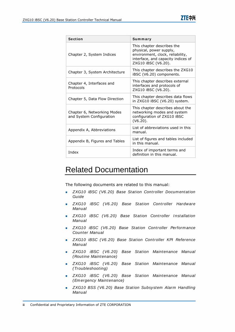
Chapter 1, System Overview
This chapter describes the system background, features, appearance, and standards complied in ZXG10 iBSC (V6.20) system, and its position.
ZXG10 iBSC (V6.20) Base Station Controller Technical Manual
ii Confidential and Proprietary Information of ZTE CORPORATION
Section Summary
Chapter 2, System Indices
This chapter describes the physical, power supply, environment, clock, reliability, interface, and capacity indices of ZXG10 iBSC (V6.20).
Chapter 3, System Architecture This chapter describes the ZXG10 iBSC (V6.20) components.
Chapter 4, Interfaces and Protocols
This chapter describes external interfaces and protocols of ZXG10 iBSC (V6.20).
Chapter 5, Data Flow Direction This chapter describes data flows in ZXG10 iBSC (V6.20) system.
Chapter 6, Networking Modes and System Configuration
This chapter describes about the networking modes and system configuration of ZXG10 iBSC (V6.20).
Appendix A, Abbreviations List of abbreviations used in this manual.
Appendix B, Figures and Tables List of figures and tables included in this manual.
Index Index of important terms and definition in this manual.
Related Documentation
The following documents are related to this manual:
ZXG10 iBSC (V6.20) Base Station Controller Documentation Guide
ZXG10 iBSC (V6.20) Base Station Controller Hardware Manual
ZXG10 iBSC (V6.20) Base Station Controller Installation Manual
ZXG10 iBSC (V6.20) Base Station Controller Performance Counter Manual
ZXG10 iBSC (V6.20) Base Station Controller KPI Reference Manual
ZXG10 iBSC (V6.20) Base Station Maintenance Manual (Routine Maintenance)
ZXG10 iBSC (V6.20) Base Station Maintenance Manual (Troubleshooting)
ZXG10 iBSC (V6.20) Base Station Maintenance Manual (Emergency Maintenance)
ZXG10 BSS (V6.20) Base Station Subsystem Alarm Handling Manual
About this Manual
Confidential and Proprietary Information of ZTE CORPORATION iii
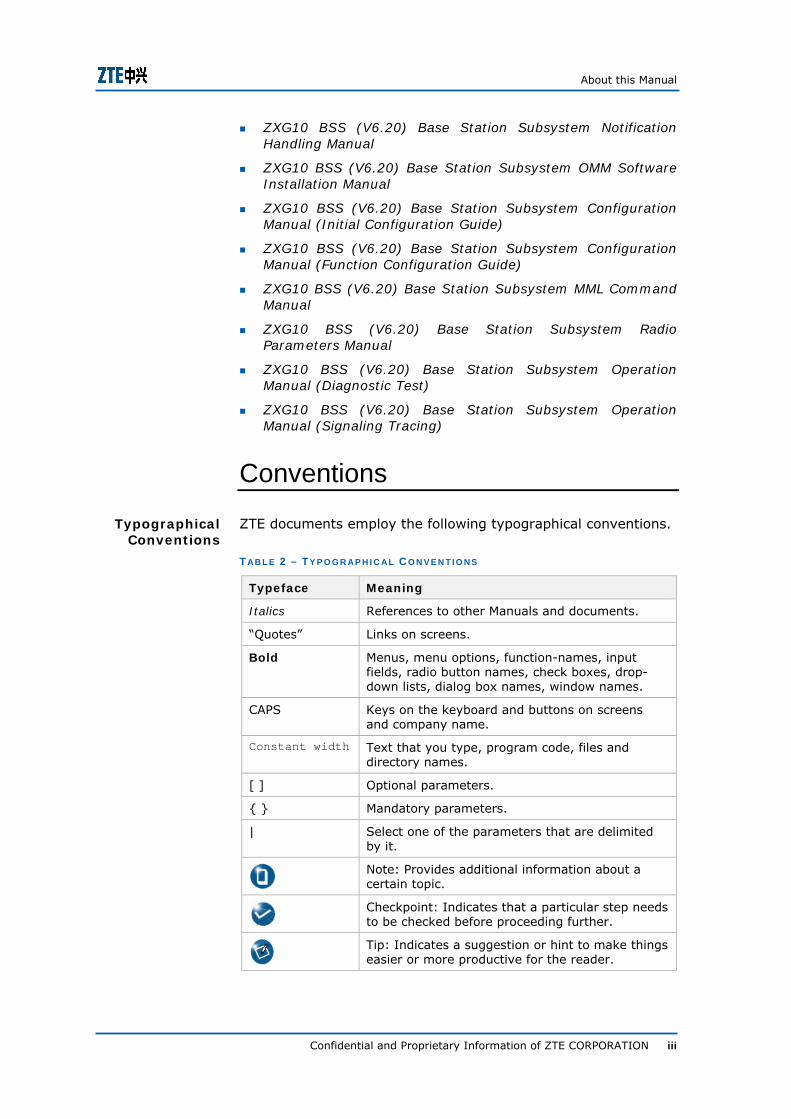
ZXG10 BSS (V6.20) Base Station Subsystem Notification Handling Manual
ZXG10 BSS (V6.20) Base Station Subsystem OMM Software Installation Manual
ZXG10 BSS (V6.20) Base Station Subsystem Configuration Manual (Initial Configuration Guide)
ZXG10 BSS (V6.20) Base Station Subsystem Configuration Manual (Function Configuration Guide)
ZXG10 BSS (V6.20) Base Station Subsystem MML Command Manual
ZXG10 BSS (V6.20) Base Station Subsystem Radio Parameters Manual
ZXG10 BSS (V6.20) Base Station Subsystem Operation Manual (Diagnostic Test)
ZXG10 BSS (V6.20) Base Station Subsystem Operation Manual (Signaling Tracing)
Conventions
ZTE documents employ the following typographical conventions.
T AB L E 2 – TY P O G R AP H I C A L C O N V E N T I O N S
Typeface Meaning
Italics References to other Manuals and documents.
“Quotes” Links on screens.
Bold Menus, menu options, function-names, input fields, radio button names, check boxes, drop-down lists, dialog box names, window names.
CAPS Keys on the keyboard and buttons on screens and company name.
Constant width Text that you type, program code, files and directory names.
[ ] Optional parameters.
{ } Mandatory parameters.
| Select one of the parameters that are delimited by it.
Note: Provides additional information about a certain topic.
Checkpoint: Indicates that a particular step needs to be checked before proceeding further.
Tip: Indicates a suggestion or hint to make things easier or more productive for the reader.
Typographical Conventions

ZXG10 iBSC (V6.20) Base Station Controller Technical Manual
iv Confidential and Proprietary Information of ZTE CORPORATION
T AB L E 3 – M O U S E OP E R AT I O N C O N V E N T I O N S
Typeface Meaning
Click Refers to clicking the primary mouse button (usually the left mouse button) once.
Double-click Refers to quickly clicking the primary mouse button (usually the left mouse button) twice.
Right-click Refers to clicking the secondary mouse button (usually the right mouse button) once.
Drag Refers to pressing and holding a mouse button and moving the mouse.
How to Get in Touch
The following sections provide information on how to obtain support for the documentation and the software.
If you have problems, questions, comments, or suggestions regarding your product, contact us by e-mail at [email protected]. You can also call our customer support center at (86) 755 26771900 and (86) 800-9830-9830.
ZTE welcomes your comments and suggestions on the quality and usefulness of this document. For further questions, comments, or suggestions on the documentation, you can contact us by e-mail at [email protected]; or you can fax your comments and suggestions to (86) 755 26772236. You can also browse our website at http://support.zte.com.cn, which contains various interesting subjects like documentation, knowledge base, forum, and service request.
Mouse Operation
Conventions
Customer Support
Documentation Support

Confidential and Proprietary Information of ZTE CORPORATION v
Declaration of RoHS Compliance
To minimize the environmental impact and take more responsibility to the earth we live, this document shall serve as formal declaration that the ZXG10 iBSC (V6.20) Base Station Controller manufactured by ZTE CORPORATION is in compliance with the Directive 2002/95/EC of the European Parliament - RoHS (Restriction of Hazardous Substances) with respect to the following substances:
Lead (Pb)
Mercury (Hg)
Cadmium (Cd)
Hexavalent Chromium (Cr(VI))
PolyBrominated Biphenyls (PBB’s)
PolyBrominated Diphenyl Ethers (PBDE’s)
The usage of the above substances in ZXG10 iBSC (V6.20) is explained in Table 4.
T AB L E 4 – U S AG E E X P L A N A T I O N O F T H E H AZ AR D O U S S U B S T AN C E S I N ZXG10 I BSC (V6.20 )
Hazardous substances
Names of Parts
Pb Hg Cd Cr(VI) PBB’s PBDE’s
System × 0 0 0 0 0
Cables and Assembly 0 0 0 0 0 0
Auxiliary Equipment × × × × × ×
Table Explanation:
0: The usage of the substance in all of the components is less than the allowed values given by 2002/95/EC standard.
×: The usage of the substance in at least one of the components is beyond the allowed values given by 2002/95/EC standard.

ZXG10 iBSC (V6.20) Base Station Controller Technical Manual
vi Confidential and Proprietary Information of ZTE CORPORATION
The ZXG10 iBSC (V6.20) Base Station Controller manufactured by ZTE CORPORATION meet the requirements of EU 2002/95/EC; however, some assemblies are customized to client specifications. Addition of specialized, customer-specified materials or processes which do not meet the requirements of EU 2002/95/EC may negate RoHS compliance of the assembly. To guarantee compliance of the assembly, the need for compliant product must be communicated to ZTE CORPORATION in written form.
This declaration is issued based on our current level of knowledge. Since conditions of use are outside our control, ZTE CORPORATION makes no warranties, express or implied, and assumes no liability in connection with the use of this information.
Confidential and Proprietary Information of ZTE CORPORATION 1
C h a p t e r 1
System Overview
This chapter describes the system background, functions, appearance, and standards complied in ZXG10 iBSC (V6.20) system, and its position.
System Background
GSM, as the second generation mobile cell communication system, voice service as primary one, has been extensively applied. But with the development of mobile communication technology and diversity of service, demands on mobile data service is increasing. Demands on data service is more urgent than before, along with the demands increased for GSM equipment, including IP Gb interface, Iu interface merge, mass capacity data interface, and merge with 3G service.
To meet above demands, ZTE developed ZXG10 iBSC (V6.20) independently.
Position of iBSC in Network
When TC is internal, the position of ZXG10 iBSC (V6.20) in the network is shown in Figure 1.

ZXG10 iBSC (V6.20) Base Station Controller Technical Manual
2 Confidential and Proprietary Information of ZTE CORPORATION
F I G U R E 1 – PO S I T I O N O F I BSC I N T H E N E T W O R K (TC I S I N T E R N AL )
When TC is external, the position of iBSC in the network is shown in Figure 2.
F I G U R E 2 – PO S I T I O N O F I BSC I N T H E N E T W O R K (TC I S E X T E R N AL )
GERAN
Gb
Ater
IuGSM/ UMTS Core Network
MSUm
Iur-g
iBSC
BTS
BTS
BSS
BSS
MS
Iur-g
UTRANRNC
iTC A
ZXG10 iBSC (V6.20) is a part of GERAN (the GSM/EDGE Radio Access Network). GERAN includes one or multiple BSSs, and one BSS consists of one BSC and one or multiple BTSs. BSC is connected with BTS via Abis interface, and BSC-BSC, BSC-RNC are connected with each other via Iur-g interface.
If TC is internal, GERAN is connected with GSM/UMTS Core Network via A/Gb/Iu interface. GERAN has two working modes: A/Gb mode and Iu mode and can work in these two modes at the same time. In this case, the 2G MS uses A/Gb working mode, the working mode used by the MS supporting Iu mode depends on GERAN and MS together.

Chapter 1 - System Overview
Confidential and Proprietary Information of ZTE CORPORATION 3
iBSC Appearance
ZXG10 iBSC (V6.20) effect diagram is shown in Figure 3.
F I G U R E 3 - ZXG10 I BSC E F F E C T D I AG R A M
When the door is opened, inner structure layout of ZXG10 iBSC cabinet is shown in Figure 4.

ZXG10 iBSC (V6.20) Base Station Controller Technical Manual
4 Confidential and Proprietary Information of ZTE CORPORATION
F I G U R E 4 - CAB I N E T L AY O U T S C H E M AT I C D I AG R AM
1
3
4
2
5
1. Power distribution box; 2. Fan box; 3. Blank IU slot; 4. Service box; 5. Dustproof box
For different portions of detailed introduction, see ZXG10 iBSC (V6.20) Base Station Controller Hardware Manual.

Chapter 1 - System Overview
Confidential and Proprietary Information of ZTE CORPORATION 5
System Functions
ZXG10 iBSC (V6.20) supports the service functions of base station controller in GSM Phase II and Phase II+ standards. Its main functions are as follows:
Supports GSM 900, GSM 850, GSM 1800 and GSM 1900 network.
Supports the base station management functions in the standard. It can manage the hybrid access of ZXG10 BTS series products.
By OMC interface and NetNumen M31 connection, implement operation and maintenance management of BSS.
Supports various types of services.
i. Circuit Voice Services
Full rate voice service
Advanced full rate voice service
Half rate voice service
AMR voice service
AMR is one of the voice coding algorithms with variable rate. It adjusts the voice coding rate automatically according to the C/I value to ensure the best voice quality under different C/I.
According to the protocol, there are 8 AMR-FR voice coding rates. ZXG10 iBSC (V6.20) supports all 8 modes. And there are 5 AMR-HR voice coding rates (7.4 kbps, 6.7 kbps, 5.9 kbps, 5.15 kbps, 4.75 kbps), all supported by ZXG10 iBSC (V6.20).
ii. Circuit Data Services
14.4 kbps full rate data service
9.6 kbps full rate data service
4.8 kbps full rate data service
2.4 kbps full rate data service
iii. Short Message Service, Chinese SMS supported
Point to point SMS in case that MS is the called party
Point to point SMS in case that MS is the calling party
Cell broadcast service from SMS center or operation & maintenance system
iv. GPRS Service
At present, main services available are point to point interactive telecommunication services, such as access database, session service, Tele-action service and so on.
ZXG10 iBSC (V6.20) Base Station Controller Technical Manual
6 Confidential and Proprietary Information of ZTE CORPORATION
v. EDGE Service
Supports channel management, including ground channel management, service channel management and control channel management.
Ground channel management
It includes the ground channel management between MSC and BSC, the ground channel management between BSC and BTS and the channel management between BSC and SGSN.
Service channel management includes channel allocation, link monitoring, channel release, and function control determination.
Available channels: FCCH, SCH, BCCH, PCH, AGCH, RACH, SDCCH, SACCH, FACCH, PACCH, PAGCH, PBCCH, PCCCH, PPCH, PRACH, and PTCCH.
Supports frequency hopping
Supports DTX and VAD
Supports various handover types
Supports synchronous handover, non-synchronous handover and pseudo-synchronous handover.
Supports the handover intra 900 MHZ frequency band, 1800 MHZ frequency band and between 900 MHZ and 1800 MHZ frequency band.
Handles handover measurement and switch over.
Supports the handover originated by network since service or interference management.
Supports the handover between the channels with different voice coding rate.
Supports the handover when using DTX.
Supports the handover caused by traffic.
Supports the concentric ring handover based on carrier-to-interference ratio.
Supports 6-level static power control and 15-level dynamic power control of MS and BTS. Supports fast power control based on reception quality.
Supports overload and flow control
iBSC is able to locate and analyze the overload, and send the cause to the background. If the traffic is too heavy, control the flow at A interface, Abis interface, and/or Gb interface to reduce the flow and guarantee maximum network utilization.
Supports call-reestablishment when radio link is faulty
iBSC supports call queuing and forced call release during assignment and handover.

Chapter 1 - System Overview
Confidential and Proprietary Information of ZTE CORPORATION 7
High end user preferential access
High end user preferential access, also called high priority user preferential access or EMLPP. It is used to divide the users into different priorities, and allocate the channel resource to the users according to the priority. The higher the priority of the user is, the easier to access the network.
Supports Co-BCCH.
Co-BCCH is usually used in dual-frequency common cell. Dual-frequency common cell is a cell that supports the carriers of two frequency bands, and the carriers of different carrier bands share one BCCH.
Co-BCCH networking has the following advantages:
Save one BCCH time slot
Configure the 1800 MHz carrier directly in 900 MHz cell. There is no need to change the original cell adjacent relation, re-arrange network, and no need to consider the reselection and handover between the dual-frequency cell with common site.
Supports dynamic HR channel conversion
ZXG10 iBSC supports dynamic HR channel conversion. System is able to adjust HR/FR channel dynamically according to the traffic, and realize the conversion between HR/FR channels automatically.
Supports flow control
Flow control is a method to protect the system. It controls the overload by limiting some services to ensure that the system runs normally.
Supports dynamic radio channel allocation
ZXG10 iBSC supports the dynamic allocation of CS and PS channels.
In dynamic radio channel allocation, the logic type of radio channel is generated according to the current call type rather than configured at background NM. The advantage of dynamic radio channel is that it uses the radio resource the best according to the service type.
ZXG10 iBSC allocates the channel according to various factors, such as channel rate selection, carrier priority, interference band, the channel allocation in intra-cell handover, allocation of reservation channel, and the selection of sub-cell channel.
Supports voice version selection
ZXG10 iBSC provides the function of setting prior voice version; one prior voice version can be set for full rate and half rate channel. Full rate voice version is one of version I (FR), version II (EFR) and version III (AMR); half rate voice

ZXG10 iBSC (V6.20) Base Station Controller Technical Manual
8 Confidential and Proprietary Information of ZTE CORPORATION
rate voice version is one of version I (HR) and version III (AMR).
Supports 3 digits network number
ZXG10 iBSC supports 3 digits network number. The current network number can be set as 2 or 3 digits. It interprets the MNC in the received signaling message at A interface and Gb interface, confirms the MNC format in the transmitted signaling, and confirms the MNC format in the broadcast message at Um interface according to the network number.
Supports the handover between 2G/3G system
Support incoming handover from 3G to 2G in CS service
Support outgoing handover from 2G to 3G in CS service
Supports full dynamic Abis
Full dynamic Abis is that the corresponding relation of radio channel and Abis transmission channel is not generated in operation & maintenance system, but is configured dynamically in service process. Dynamic Abis is to provide more bandwidth in case the Abis transmission bandwidth is fixed.
Supports coding control
Compared with GPRS, the measurement report of EDGE is improved a lot. The EDGE measurement is based on each pulse, which means the measurement is performed by the granularity of Burst.
The fast measurement of EDGE makes the network is able to respond the change of the radio environment rapidly so that it can select the most proper coding mode and carry out power control.
In downlink direction, iBSC supports selecting the coding mode by time slot and by TBF.
In uplink direction, iBSC selects the uplink TBF coding mode according to the measurement parameters of the uplink channel reported by BTS.
Supports retransmission
In packet service, the negative feedback is employed to control the retransmission, which means that the transmitter finds out the packets that are not received correctly by the receiver according to the bitmap fed back from the receiver, then determines if to retransmit the corresponding packet.
In GPRS, the packet data is retransmitted in original transmission coding mode, for example, the block transmitted in CS4 coding is retransmitted in CS4 mode.
In EDGE, there are two new retransmission methods: segmentation and reassembly, and incremental redundancy.
Optimization of packet channel allocation algorithm

Chapter 1 - System Overview
Confidential and Proprietary Information of ZTE CORPORATION 9
ZXG10 iBSC supports the multiple time slot ability of the MS. It allocates GPRS TBF or EDGE TBF to the MS according to the different GPRS/EDGE availability of MS.
When ZXG10 iBSC allocates the PDTCH channel to the MS, it selects the carrier with lower load first; after selecting the carrier, it selects the most proper PDTCH channel combination in the carrier according to the MS requirement.
Supports satellite Abis and satellite Gb
There is a bi-directional time delay about 540 ms, which impacts the GRPS and EDGE services a lot. ZXB10 iBSC eliminates this impact as much as possible and ensures that the GPRS and EDGE services run normally.
Supports various interfaces
ZXG10 iBSC supports STM-1 interface, GE interface, and E1 interface.
Supports UMTS QoS
After the GSM network evolves into GERAN, operators can provide more powerful services for users due to the high-speed packet data transmission brought by EDGE. These services include conversational service, stream media service, and interactive service. ZXG10 iBSC supports various service quality requirements of different services, i.e. QoS.
Supports extended uplink dynamic TBF
Before the extended uplink dynamic allocation is applied in GPRS system, the number of uplink channels available for uplink TBF is always less than the number of occupied downlink channels. ZXG10 iBSC supports the extended uplink dynamic TBF and realizes that the number of uplink channels is larger than the number of downlink channels, which better satisfies the service requirement.
Supports multi-signaling-point connection
According to the ITU-T specification, the maximum number of signaling links between two signaling points is 16, and the maximum number of circuits is 4096. With the development of mobile network, the number of users increases greatly. The maximum number of signaling links and the maximum number of circuits can not satisfy the on-site service requirement.
ZXG10 iBSC adopts the unified 3G platform to support multi-signaling-point connection. In other words, one iBSC can connect multiple MSCs.
Supports intelligent power-off
When the system performance data reaches the threshold value for power-on/off, ZXG10 iBSC sends message to notify BTS to perform the power-on/off operation.
ZXG10 iBSC can merge disperse distributed multiple timeslots within a certain segment into the carrier with

ZXG10 iBSC (V6.20) Base Station Controller Technical Manual
10 Confidential and Proprietary Information of ZTE CORPORATION
minimum quantity, to power off for unused carrier to save power consumption. During timeslot combination, it prefers to merge to BCCH carrier.
ZXG10 iBSC supports customized intelligent power off function at different period, which can avoid network influence caused by enabling intelligent power off during busy time.
Supports TFO
Tandem Free operation (TFO) refers to the following process:
After a call is established, the two Transcoders (TC) perform in-band negotiation for the Codec used, to avoid unnecessary voice coding conversion at the sending end and the receiving end during the call process.
TFO improves the voice quality and reduces the transmission delay.
Supports transparent channel
The transparent channel realizes transparent data transmission between a timeslot of E1 at one end’s interface and that at the other end’s interface.
If E1 cables at the two ends of the transparent channel are in the same shelf, this function can be realized by the circuit switching of UIMU of the shelf.
If E1 cables at the two ends of the transparent channel are in different shelves, this function is realized by transparent data forwarding through DSP (the DSP is used to process user plane data).
ZXG10 iBSC supports the following transparent channels:
The transparent channel between Abis interface and A-interface
The transparent channel between Abis interface and Abis interface
The transparent channel between A-interface and A-interface
The transparent channel between Abis interface and Ater interface (if TC is remote)
Supports EGPRS and GPRS channel scheduling
Take GPRS MS for example. The channel scheduling process is as follows:
Allocate the GPRS channel for GPRS MS first. If the EGPRS channel is idle and the GPRS channel load is heavy, the GPRS MS can be allocated with EGPRS channel. If the EGPRS channel load becomes heavy or the GPRS channel is idle, the GPRS MS can migrate to the GPRS channel.
Supports Dual Transfer Mode (DTM)

Chapter 1 - System Overview
Confidential and Proprietary Information of ZTE CORPORATION 11
ZXG10 iBSC supports the Dual Transfer Mode (DTM). ZXG10 iBSC can perform CS/PS service simultaneously under A/Gb mode.
Supports user tracing function
ZXG10 iBSC realizes single-user signaling-tracing function according to user’s identification IMSI, TMSI, or TLLI.
Supports PS paging coordination
ZXG10 iBSC supports PS paging coordination, that is, under the packet transmission state, iBSC can make MS intercept the circuit paging message.
Support FLEX A
FLEX A means one BSC can connect to multiple MSCs at the same time, these MSCs can form many MSC POOLs.
FLEX A networking is very flexible, in comparison to traditional MSC, the service provided by a MSC POOL has following advantages:
Expand a MSC service region, reduce inter-MSC handover, and position region, HLR frequency and traffic update.
Utilization of network equipment is increased. In a MSC POOL, VLR/MSC belonging to MS can be relatively fixed, when traffic is suddenly increased in a hotspot region, the load of certain MSC will not be increased with it.
Increase disaster relief capability for whole network. When a MSC fails in MSC POOL, its traffic will be transferred to other MSCs in the region.
FLEX A networking is transparent for MS, that is, MS doesn’t participate in changing of networking mode.
Support FLEX Gb
FLEX Gb means one BSC can be connected to multiple SGSNs, which forms a SGSN POOL.
FLEX Gb networking is very flexible, in comparison to traditional MSC, the service provided by a MSC POOL has following advantages:
Expand a SGSN service region, reduce inter-SGSN PS handover, and position region, HLR frequency and traffic update.
Utilization of network equipment is increased. In a SGSN POOL, VLR/ SGSN belonging to MS can be relatively fixed, when traffic is suddenly increased in a hotspot region, the load of certain SGSN will not be increased with it.
Increase disaster relief capability for whole network. When a SGSN fails in SGSN POOL, its traffic will be transferred to other SGSNs in the region.
FLEX Gb networking is transparent for MS, that is, MS doesn’t participate in changing of networking mode.

ZXG10 iBSC (V6.20) Base Station Controller Technical Manual
12 Confidential and Proprietary Information of ZTE CORPORATION
Support preemption and queuing
Preemption of packet service is to consider all dynamic & static packet channel while assigning packet radio resource based on user QoS requirements, if idle radio resource on channel can’t meet QoS requirements or user number on channel reaches upper limit, and current user can do preemption, BSS will try to release one or more radio resource for users with low priority to current service.
Queuing of packet service means when BSC can’t get sufficient packet radio resource based on user QoS requirements, the system will do its best to assign packet radio resource to enable service access, and then queue to wait for getting radio resource that can meet user QoS requirements.
Under the case of BSC supporting preemption and queuing, first do preemption of packet service; if failed, do queuing.
Support secondary cell reselection in external network
Secondary cell reselection in external network can increase the access speed in new cell while doing MS reselection for external cell, shorten cell reselection time during MS data transmission, increase data transmission rate to improve service feeling of end users.
Support network control cell reselection
Network control cell reselection means BSC receives the measurement report submitted by MS, do storage and weight average processing for measurement level value in service cell and adjacent cell, and gain decisions based on processing results and network service loads.
Network control cell reselection can fully use the information held by network to do reasonable decision, implementing optimized service allocation in network; at the same time, it can reduce useless cell reselection made by MS, to increase TBF data transmission efficiency, enable end user gain the best service quality.
Support uplink incremental redundancy
Incremental redundancy is one of link quality control modes for EDGE. Under uplink incremental redundancy mode, when BTS successfully decodes RLC header successfully and failed to decode a data block, BTS stores the undecoded data block and notify of MS. MS uses another boring hole mode to re-transmit coding data block, BTS can independently decode the data block; if failed, it can do joint decoding by combining the data block that is failed to decode. Because data block coded with different boring hole modes includes different redundant information. This will increase the redundant information quantity and success probability to successful decoding.
Support ZXSDR BS8800 GU360

Chapter 1 - System Overview
Confidential and Proprietary Information of ZTE CORPORATION 13
ZXSDR BS8800 GU360 is indoor macro BS product with new generation platform, using multiple carrier technology and the architecture with baseband and separating RF, implementing GSM/WCDMA common-mode.
Support different networks
ZXG10 iBSC supports to share radio network among different operators, that is, different operators can configure respective cells at same site, to reach common access by multiple operators.
Support voice Noise reduction and level control
Noise reduction function can improve voice SNR (signal noise ratio), voice quality, and comfort of communication environment.
Level control can optimize signal level, to reach the purpose of increasing communication quality.
TFO function is mutually exclusive with noise reduction and level control, that is, to establish TFO represents don’t activate noise reduction and level control function.
Support high-level multiple timeslot capability for PS service
ZXG10 iBSC supports high-level multiple timeslot capability for PS service, downlink of single service can assign up to 5 timeslot transmission data, and downstream rate can be increased to 296Kbps. Higher transmission rate will obviously improve user feeling of FTP file transfer and receiving & transmitting mails.
Support IP transmission mode in A interface
With evolution of network technology, transmission resource based on IP is easier to gain. Relative to traditional circuit network, utilization of IP network is higher, and networking mode is more flexible.
ZXG10 iBSC supports IP carrier through A interface, which is useful for the development to all-IP direction, enables easier merging between GSM and future transmission network.
ZXG10 iBSC supports IP transmission mode at A interface only if hardware is using Gigabyte platform, if the hardware uses Million byte platform, the IP transmission mode at A interface is not supported.
System Features
ZXG10 iBSC (V6.10) is the high capacity base station controller developed by ZTE cooperation independently, and the following are the main features:
All IP hardware platform

ZXG10 iBSC (V6.20) Base Station Controller Technical Manual
14 Confidential and Proprietary Information of ZTE CORPORATION
ZXG10 iBSC employs the all IP hardware platform the same as the 3G products of ZTE Corporation. The hardware platform based on all IP ensures powerful PS service support capability and facilitates to realize IP Abis interface and IP Gb interface.
High capacity and strong processing capability
ZXG10 iBSC (V6.10) supports maximum 1536 sites and 3072 carriers with strong processing capability. High capacity and strong processing capability can reduce the complexity of networking, improve network quality and save the investment on equipment room.
Standard A interface
ZXG10 iBSC (V6.10) provides completely open A interface to ensure the interconnection of the equipment from different vendors.
Modularization, easy capacity expansion
ZXG10 iBSC (V6.10) employs modularized design, which facilitates the capacity expansion. Smooth expansion can be realized by module overlay.
Flexible networking mode
ZXG10 iBSC (V6.10) supports star, link, tree and ring networking of Abis interface, and also supports transmission equipment such as E1, satellite, microwave and optical fiber.
High integration and low power consumption
ZXG10 iBSC (V6.10) is highly integrated and occupies less area, which saves the investment in the equipment room.
ZXG10 iBSC (V6.10) has low overall power consumption, which reduces the operator’s investment on auxiliary power and air conditioning.
High reliability
The key components of ZXG10 iBSC (V6.10) employs 1+1 redundancy backup, which increases the system reliability.
Standards Complied
ZXG10 iBSC (V6.20) development standards are given below:
3GPP 23.060 – General Packet Radio Service (GPRS) – Service description – Stage 2 (Release 5) – version V5.10.0
3GPP 44.160 – General Packet Radio Service (GPRS) – Mobile Station (MS) – Base Station System (BSS) interface – Radio Link Control/Medium Access Control (RLC/MAC)protocol Iu mode(Release 5) – version V5.8.0
3GPP 43.051 – Radio Access Network – Overall description – Stage 2 – (Release 5) –version V5.10.0

Chapter 1 - System Overview
Confidential and Proprietary Information of ZTE CORPORATION 15
3GPP 23.221 – Technical Specification Group Services and System Aspects – Architectural requirements(Release 5) – version V5.11.0
3GPP 23.236 – Intra-domain connection of Radio Access Network (RAN) nodes to multiple Core Network (CN) nodes (Release 5) – version V5.3.0
3GPP 24.008 – Mobile radio interface Layer 3 specification – Core network protocols – Stage 3(Release 5) – V5.13.0
3GPP 25.323 – Packet Data Convergence Protocol (PDCP) specification (Release 5) – Version V5.4.0
3GPP 48.016 – General Packet Radio Service (GPRS) – Base Station System (BSS) – Serving GPRS Support Node (SGSN) interface – Network service – Version V5.4.0
3GPP 48.018 – General Packet Radio Service (GPRS) – Base Station System (BSS) – Serving GPRS Support Node (SGSN) – BSS GPRS protocol (BSSGP) – version V5.13.0
3GPP 44.018 - Mobile radio interface layer 3 specification – Radio Resource Control (RRC) protocol (Release 5) – version V5.20.0
3GPP 44.060 – General Packet Radio Service (GPRS) – Mobile Station (MS) – Base Station System (BSS) interface – Radio Link Control/Medium Access Control (RLC/MAC) protocol(Release 5) – version V5.10.0
3GPP 44.118 – Mobile radio interface layer 3 specification – Radio Resource Control (RRC) protocol – Iu Mode (Release 6) – version V6.4.1
3GPP 44.008 – Technical Specification Group GSM/EDGE Radio Access Network – Radio subsystem link control (Release 5) – version V5.19.0
3GPP 43.130 – Iur-g interface – Stage 2 – version V5.0.0
3GPP 23.271 – Functional stage 2 description of Location Services (LCS) – version V5.13.0
3GPP 45.002 – Multiplexing and multiple access on the radio path – version V5.13.0
3GPP 43.059 – Functional stage 2 description of Location Services (LCS) in GERAN – version V5.5.0
3GPP 49.031 – Location Services (LCS) – Base Station System Application Part LCS Extension (BSSAP-LE) – version V5.4.0
3GPP 48.071 - Location Services (LCS); Serving Mobile Location Centre - Base Station System (SMLC-BSS) interface; Layer 3 specification – version V5.1.0
3GPP 44.031 - Location Services (LCS); Mobile Station (MS) - Serving Mobile Location Centre (SMLC) Radio Resource LCS Protocol (RRLP) – version V5.13.0

ZXG10 iBSC (V6.20) Base Station Controller Technical Manual
16 Confidential and Proprietary Information of ZTE CORPORATION
3GPP 44.071 - Location Services (LCS); Mobile Radio Interface Layer 3 LCS Specification – version V5.0.1
3GPP 48.008 – Mobile Switching Centre – Base Station System(MSC-BSS) interface – Layer 3 specification(Release 5) – version V5.12.0

Confidential and Proprietary Information of ZTE CORPORATION 17
C h a p t e r 2
System Indices
This chapter contains following topics:
Physical Indices
Power Supply Indices
Environmental Conditions
Clock Indices
Reliability Indices
Interface Indices
Capacity Indices
Physical Indices
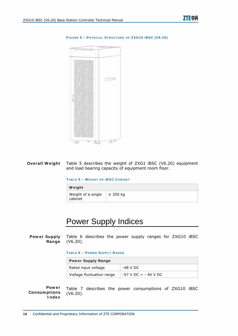
Physical structure of ZXG10 iBSC (V6.20) is the same as ZXWR RNC. Structure of ZXG10 iBSC cabinet is shown in Figure 5.
Excluding left & right side door panel: H X W X D = 2000 mm X 600 mm X 800 mm
Including left & right side door panel: H X W X D = 2000 mm X 650 mm X 800 mm
Note:
Outline dimension for whole cabinet: 2000 mm X 600 mm X 800 mm (H X W X D), width for single side panel is 25 mm.
Size
ZXG10 iBSC (V6.20) Base Station Controller Technical Manual
18 Confidential and Proprietary Information of ZTE CORPORATION
F I G U R E 5 – PH Y S I C AL S T R U C T U R E O F ZXG10 I BSC (V6 .20)
Table 5 describes the weight of ZXG1 iBSC (V6.20) equipment and load bearing capacity of equipment room floor.
T AB L E 5 – W E I G H T O F I BSC C AB I N E T
Weight
Weight of a single cabinet
≤ 350 kg
Power Supply Indices
Table 6 describes the power supply ranges for ZXG10 iBSC (V6.20).
T AB L E 6 – P O W E R S U P P L Y R AN G E
Power Supply Range
Rated input voltage -48 V DC
Voltage fluctuation range -57 V DC ~ - 40 V DC
Table 7 describes the power consumptions of ZXG10 iBSC (V6.20).
Overall Weight
Power Supply Range
Power Consumptions
Index

Chapter 2 - System Indices
Confidential and Proprietary Information of ZTE CORPORATION 19
T AB L E 7 – P O W E R C O N S U M P T I O N O F ZXG10 I BSC (V6 .20)
Power Consumption
Power consumption of fully-configured single cabinet
1779 W
Power consumption of fully-configured dual-cabinet
4165 W
Environmental Conditions
The ZXG10 iBSC (V6.20) cabinet can be upper-grounded or lower-grounded.
Table 8 describes ZXG10 iBSC grounding indices:
T AB L E 8 – GR O U N D I N G R E Q U I R E M E N T S O F ZXG10 I BSC (V6 .20)
Index Range
Cabinet grounding resistance 0.1 Ω ~ 0.3 Ω
Equipment room grounding resistance < 1 Ω
Table 9 describes the temperature and humidity requirements.
T AB L E 9 – TE M P E R AT U R E A N D H U M I D I T Y R E Q U I R E M E N T S F O R I BSC(V6 .20)
Requirement Range
Long-term operating temperature: 0˚C ~ 40˚C Operating temperature Short-term operating temperature: -5˚C ~ 45˚C
Relative humidity for long-term operation: 20% ~ 90%
Relative humidity
Relative humidity for short-term operation: 5% ~ 95%
Air inside the equipment room must be free of magneto-conductive, conductive, and corrosive gases that may corrode metallic parts and degrade insulation. Table 10 describes the air pollution requirements of ZXG10 iBSC (V6.20).
T AB L E 10 – AI R P O L L U T I O N AN D AT M O S P H E R I C P R E S S U R E R E Q U I R E M E N T S
Requirement Range
Density of dust particles with a diameter larger than 5 µm
≤3×10⁴ grains/m3
Grounding Requirements
Temperature and Humidity Requirements
Air Pollution Requirements

ZXG10 iBSC (V6.20) Base Station Controller Technical Manual
20 Confidential and Proprietary Information of ZTE CORPORATION
Clock Indices
ZXG10 iBSC (V6.20) clock indices are given in Table 11.
T AB L E 11 – CL O C K I N D I C E S O F ZXG10 IBSC (V6.20)
Index Value
Clock level Level 3 class-A clock
Minimum clock accuracy ≤ ±4.6 × 10⁻⁶
Pull-in range ≤ ±4.6 × 10⁻⁶
Maximum frequency deviation
2×10⁻⁸/day
Maximum initial frequency deviation
1 × 10⁻⁸
Clock working mode Fast pull-in, trace, hold, and free run
Clock synchronization mode
External clock synchronization, extracting from the line clock
2MBITS 2
2 MHz 2 Clock synchronization interfaces Line 8
kbps 2
Reliability Indices
Reliability indices of ZXG10 iBSC (V6.20) are shown in Table 12.
T AB L E 12 – RE L I AB I L I T Y I N D I C E S O F ZG10 I BSC (V6 .20 )
Index Value
Mean Time Between Failure (MTBF) ≥ 100,000 hours
Mean Time To Repair (MTTR) ≤ 30 minutes
System restart time <10 minutes
Interface Types
ZXG10 iBSC interface types description is shown in Table 13.
Chapter 2 - System Indices
Confidential and Proprietary Information of ZTE CORPORATION 21
T AB L E 13 - TAB L E ZXG10 I BSC I N T E R F A C E TY P E S
Transmission Type
A Interface (Connect MSC) (TC is internal)
Ater interface (connect iTC) (TC is external)
STM-1 √ √
GE √ ×
E1 √ √
T1 × ×
IPoE × ×
Transmission Type
Abis interface (connect BTS)
Gb interface (connect SGSN)
OMC interface
STM-1 √ × ×
GE √ √ √
E1 √ √ ×
T1 √ × ×
IPoE √ × ×
Capacity Indices
1. Table 14 describes the max capacity at A and Abis interface.
T AB L E 14 - C AP AC I T Y I N D E X O F A & AB I S I N T E R F AC E D U R I N G F U L L C O N F I G U R AT I O N O F T H E S Y S T E M
A interface
Abis interface E1 STM-1 IP
Abis interface capacity
624 E1 624 E1 624 E1
E1 A interface capacity
864 E1 17 pairs of STM-1
3 pairs of GE
Abis interface capacity
2 pairs of GE
2 pairs of GE
2 pairs of GE
IP A interface capacity
1248 E1 20 pairs of STM-1
3 pairs of GE
Abis interface capacity
9 pairs of STM-1
9 pairs of STM-1
9 pairs of STM-1
STM-1 A interface capacity
864 E1 17 pairs of STM-1
3 pairs of GE
IPoE Abis interface capacity
480 E1 480 E1 480 E1

ZXG10 iBSC (V6.20) Base Station Controller Technical Manual
22 Confidential and Proprietary Information of ZTE CORPORATION
A interface
Abis interface E1 STM-1 IP
A interface capacity
864 E1 17 pairs of STM-1
3 pairs of GE
2. Max capacity at Ater interface
If Abis interface uses E1 transmission, supporting up to 184 pieces of E1
If Abis interface uses IP transmission, supporting up to 176 pieces of E1
3. Max capacity at Gb interface
If Gb interface uses E1 transmission, max capacity is 256 Mbps
If Gb interface uses IP transmission, max capacity is 400 Mbps
4. Max quantity for 7 links: 16 X 64 kbit/s links or 16 X 2M No.7 link
5. Max carrier quantity for system: 3072.
6. Max site quantity for system: 1536
7. BHCA: 4200 K.
8. Max traffic: 15000 Erlang.
Confidential and Proprietary Information of ZTE CORPORATION 23
C h a p t e r 3
System Architecture
This chapter explains the following topics:
System Composition
Hardware System
Shelves
Boards
Software System
System Composition
ZXG10 iBSC (V6.20) works smoothly in the GSM system and is compatible to all parts of GSM network. It consists of the hardware system and software system.
The hardware system contains the cabinet, shelves, and boards. The software system includes the foreground software and the background software.
Hardware System
Figure 6 shows the structure of ZXG10 iBSC (V6.20) hardware system.
Overview

ZXG10 iBSC (V6.20) Base Station Controller Technical Manual
24 Confidential and Proprietary Information of ZTE CORPORATION
F I G U R E 6 – ZXG10 I BSC (V6 .20 ) H AR D W AR E S Y S T E M D I AG R AM
电源、风扇
处理单元
操作维护单元
外围设备监控单元
接入单元
交换单元
ZXG10 iBSC
BTS
MSC
SGSN
ZTE
TC单元
Processing unit
TC unit
O&M unit
Power, Fan
Peripheral device monitoring unit
Logically, ZXG10 iBSC (V6.20) consists of six units:
Access unit
This unit provides the following interface access processing for iBSC:
A-interface/Ater interface
Abis interface
Gb interface
This unit includes:
A-Interface Unit (AIU) (when TC is external, AIU belongs to iTC system, and the Ater interface unit NSMU is added between iBSC and iTC)
Abis Interface Unit (BIU)
Gb Interface Unit (GIU)
Switching unit
This unit provides a large-capacity platform without congestion.
Processing unit
This unit performs upper-level protocol processing for system control plane and user plane.
O&M unit
This unit performs management for iBSC system, and provides global configuration data storage and OMC interfaces.
Peripheral device monitoring unit
This unit performs detecting and alarm for iBSC cabinet power and environment, and detecting and controlling for the cabinet fan.
Chapter 3 - System Architecture
Confidential and Proprietary Information of ZTE CORPORATION 25
TC unit
This unit performs transcoding and rate adaptation. When TC is external, this part is realized by iTC.
Shelves
ZXG10 iBSC (V6.20) system includes three shelves: control shelf, resource shelf, and packet switching shelf. The functional description of each shelf is given in Table 15.
T AB L E 15 – SH E L V E S D E S C R I P T I O N
Shelf Type Functions
Control Shelf
Implements the system global operation and maintenance, global clock function, control plane processing, and control plane Ethernet switching functions.
Resource Shelf Implements the system access and form various common service processing sub-systems.
Packet Switching Shelf
Provides non-blocking IP switching platform with large-capacity.
Refer to ZXG10 iBSC (V6.20) Base Station Controller Hardware Manual for details about shelves.
Boards
The boards configured in the shelves are classified into front board and back board according to the assembly relation. The front board and back board are inserted in the slot on the backplane. The indicators for board running status are installed on the front board panel. The back board assists the front board to lead out the external signal interface (the optical fiber is led out from front board panel) and debugging port to realize the connection between different shelves on the same rack, between different racks, and between the system and the external NE.
The description of the boards in ZXG10 iBSC (V6.20) is given in Table 16.
T AB L E 16 – ZXG10 I BSC (V6 .20 ) BO AR D S L I S T
Board Name
Functions Board Function Name
Corresponding Rear Board

ZXG10 iBSC (V6.20) Base Station Controller Technical Manual
26 Confidential and Proprietary Information of ZTE CORPORATION
Board Name
Functions Board Function Name
Corresponding Rear Board
GIPI
Provide GE interface for iBSC system. Each GIPI board provides 1 gigabyte external electrical interface or optical interface, and 1 gigabyte electrical interface for internal user
IPBB,
IPAB,
IPGB
RGER
BIPI Provide FE interface for iBSC system, there are 4 FE interfaces on each BIPI.
IPBB,
IPAB,
IPGB
RMNIC
EIPI Provide IP access for E1 EIPI
CHUB
CHUB and UIMC/UIMU together control the exchange and convergence of the system internal control plane data.
CHUB RCHB1
RCHB2
CLKG Implement the clock function of iBSC system.
CLKG RCKG1
RCKG2
ICM Finish iBSC system clock function, with GPS transceiver
ICM RCKG1,
RCKG2
CMP
Implement the service call control management in PS/CS domain, the resource management in sub-layer, such as BSSAP, BSSGP, and system itself.
CMP -
DTB Each DTB provides 32 E1 interfaces.
DTB RDTB
GLI
Provide interface and processing function for the interconnection of each resource shelf.
GLI -
GUP2
Implement code conversion, TDM package and IP package transition, user protocol processing, RTP protocol processing and packaging function
BIPB2
AIPB
DRTB2
UPPB2
TIPB2
GUP Realize the Abis interface processing, transcoding and rate adaptation.
BIPB
DRTB
TIPB
UPPB
-

Chapter 3 - System Architecture
Confidential and Proprietary Information of ZTE CORPORATION 27
Board Name
Functions Board Function Name
Corresponding Rear Board
OMP
Implement the system global processing, provide an external FE interface and operation & maintenance system connection; monitor and manage the boards in the system directly or indirectly.
OMP RMPB
PSN Implement the exchange of user plane data with large capacity.
PSN -
SDTB2 Provide 2 STM-1 standard interface with 155M capacity
SDTB2 RGIMI
SDTB Provide a standard 155M STM-1 interface.
SDTB RGIM1
SPB2
Implement signaling processing function and external E1 interface function
SPB2
GIPB2
LAPD2
RSPB
SPB Implement the signal processing and external interface function.
SPB,
GIPB,
LAPD
RSPB
SBCX
Store some files needed by OMP, and organize these files according to the requirement of operation & maintenance system.
SVR RSVB
UIMC Provide switching plane for control shelf and packet switching unit shelf.
UIMC RUIM2,
RUIM3
GUIM Provide internal platform for resource shelf.
GUIM RGUM1
RGUM2
UIMU Provide internal platform for resource shelf.
UIMU RUIM1
Note:
Each board has two names: board hardware name and board function name. The board hardware name is the board name, and board function name reflects the function that the board implements after loading the software. The same hardware board can realize a different function by loading different software.
ZXG10 iBSC (V6.20) Base Station Controller Technical Manual
28 Confidential and Proprietary Information of ZTE CORPORATION
Refer to ZXG10 iBSC (V6.20) Base Station Controller Hardware Manual for details on boards.
Software System
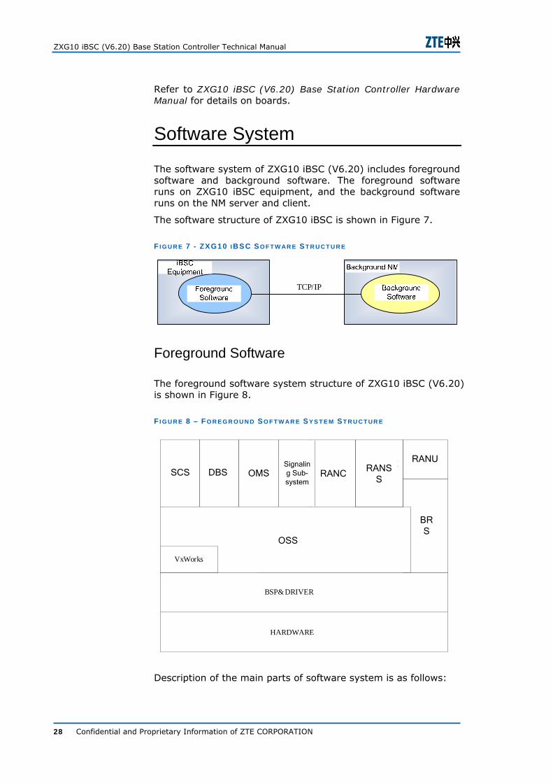
The software system of ZXG10 iBSC (V6.20) includes foreground software and background software. The foreground software runs on ZXG10 iBSC equipment, and the background software runs on the NM server and client.
The software structure of ZXG10 iBSC is shown in Figure 7.
F I G U R E 7 - ZXG10 I BSC S O F T W AR E S T R U C T U R E
iBSC设备 后台网管
前台软件 后台软件TCP/IP
Foreground Software
The foreground software system structure of ZXG10 iBSC (V6.20) is shown in Figure 8.
F I G U R E 8 – FO R E G R O U N D SO F T W AR E S Y S T E M S T R U C T U R E
HARDWARE
BSP& DRIVER
系统控制子系统(SCS)
数据库子系统
(DBS)
操作维护子系统
(OMS)
信令子
系统
RAN控制
面子系统
(RANC)
承载子系统
(BRS)操作支撑子系统(OSS)
VxWorks
RAN业务支撑子系统
(RANSS)
RAN用户面子系统
(RANU)SCS DBS OMSSignaling Sub-system
RANCRANS
S
RANU
BRS
OSS
Description of the main parts of software system is as follows:

Chapter 3 - System Architecture
Confidential and Proprietary Information of ZTE CORPORATION 29
BSP subsystem implements the hardware drivers of the whole system. It shields the upper level software module from the operation details of hardware device, extracts the hardware function and only provides the logic function level of the hardware device to the other software module.
Operation Support Subsystem (OSS) works above the BSP subsystem and below all other subsystems, it shields the user process from all device driver interfaces. The main tasks of OSS include process communication, file management, device driver and process scheduling.
Database Subsystem (DBS) works above the OSS. It manages the physical resources of NE, manages the configuration information of services, signaling and protocol, and provides the database access interface to other subsystems.
Bearer Subsystem (BRS) provides the bearer services of IP and TDM for the service support subsystem, signaling subsystem and OMS, and implements LAPD function and Frame Relay (FR) function.
Operation & Maintenance Subsystem (OMS) is a foreground realization of operation & maintenance system and LMT. It performs following functions:
Performance management
Signal tracing
Performance statistic of radio service
Service alarm, and dynamic observation of service data
System Control Subsystem (SCS) works above the OSS and DBS. It performs the monitoring, startup, and version download of the whole system.
Signaling subsystem works above OSS, DBS, and bearer subsystem. It realizes the narrow band No. 7 signaling, broadband No. 7 signaling, calling signaling, IP signaling and gateway control signaling, and it provides services to RANC and RANSS.
RAN Control Plane Subsystem (RANC) performs the following functions:
Implements processing of layer-3 control plane protocols at Um, Abis, A, and Gb interface.
BSP Subsystem
OSS
DBS
BRS
OMS
SCS
Signaling Subsystem
RANC

ZXG10 iBSC (V6.20) Base Station Controller Technical Manual
30 Confidential and Proprietary Information of ZTE CORPORATION
Implements function of calling signaling connection control, including; radio resource management, dynamic channel resource adjustment, load control, acceptance control, handover, and signaling connection management.
RAN User Plane Subsystem (RANU) performs the following functions:
For the PS in A/Gb mode and Iu mode, it provides data forwarding and scheduling at radio interface, Gb interface, and Iu interface according to the QoS demand.
For CS in A/Gb mode, it provides the TC function on GUP board.
RAN Service Support Subsystem (RANSS) provides support to control plane and user plane subsystem and performs the following functions:
Guarantees the proper process of service.
Provides monitoring of various services.
Implements iBSC global processing, including signaling tracing, load control, acceptance control, and performance measurement.
Background Software
Background software runs on the NM server and client, it is called NetNumen M31 and it communicates with iBSC by TCP/IP protocol. The main functions of NetNumen M31 mainly implements following functions:
Configuration management
Fault management
Performance management
System management
RANU
RANSS
Confidential and Proprietary Information of ZTE CORPORATION 31
C h a p t e r 4
Interfaces and Protocols
This chapter describes the following topics:
A-interface
Ater Interface
Abis interface
Gb interface
OMC Interface
Protocols in CS Domain
Protocols in PS Domain
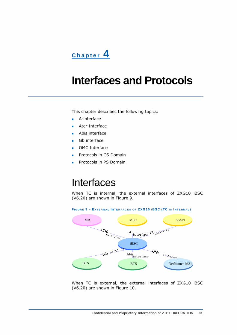
Interfaces When TC is internal, the external interfaces of ZXG10 iBSC (V6.20) are shown in Figure 9.
F I G U R E 9 – EX T E R N AL I N T E R F AC E S O F ZXG10 I BSC (TC I S I N T E R N A L )
MSC
BTS
iBSC
SGSN
Abisinterface
MR
BTS NetNumen M31
When TC is external, the external interfaces of ZXG10 iBSC (V6.20) are shown in Figure 10.

ZXG10 iBSC (V6.20) Base Station Controller Technical Manual
32 Confidential and Proprietary Information of ZTE CORPORATION
F I G U R E 10 – E X T E R N AL I N T E R F AC E S O F ZXG10 I BSC (TC I S E X T E R N AL )
iTC
BTS
iBSC
SGSN
Abisinterface
MR
BTS NetNumen M31
The functional description of ZXG10 iBSC external interfaces is given in Table 17.
T AB L E 17 – FU N C T I O N AL D E S C R I P T I O N O F ZXG10 I BSC E X T E R N AL I N T E R F AC E S
External System
External System Function
Relative Interfaces
BTS Establish the radio environment under the control of iBSC.
Abis interface, providing the control and maintenance information of BTS, and providing the transmission of voice information and GPRS data at Abis interface.
MSC (TC is internal)
Control iBSC and MS to establish voice radio channel, implement the function of voice exchange.
A-interface, providing relative message about connection establishment and deleting at A interface, forwarding the higher-level message between MS and MSC transparently, and also transmitting voice information.
SGSN
Control iBSC and MS to establish the GPRS radio channel, and implement the function of data information exchange.
Gb interface, providing relative message about connection establishment and deleting at Gb interface, forwarding the higher-level message between MS and MSC transparently, and also transmitting GPRS data information.
iTC (TC is external)
Perform the transcoding function
Ater interface, providing signaling interaction between iBSC and iTC.
NetNumen M31
The system operators maintain and control the iBSC through NetNumen M31.
OMC interface, providing the control and maintenance of iBSC through NetNumen M31.

Chapter 4 - Interfaces and Protocols
Confidential and Proprietary Information of ZTE CORPORATION 33
External System
External System Function
Relative Interfaces
MR
Finish collection and network assessment, adjacent optimization, frequency optimization for mass MR data.
CDR (call data record) interface, provide iBSC to report carrier function of mass MR data for MR.
A-Interface
The interface between BSC and MSC is called A-interface. More accurately, A-interface is the interface between TC and MSC.
Transcoder implements the voice transformation between voice coding and 64 kbps A law PCM coding. At the same time, it performs the data rate adaptation in the circuit data service. TC can be either at BSC side or MSC side.
The iBSC A-interface supports two kinds of interfaces.
In this case, iBSC is connected with MSC by 75 Ω coaxial cable or 120 Ω twisted pair.
At A-interface, data link layer employs MTP2 protocol, network layer employs MTP3 and SCCP protocol, and application layer employs BSSMAP protocol.
In this case, iBSC is connected with MSC by optical fiber.
In this case, iBSC is connected with MSC by network cable.
Ater Interface (TC is External)
The interface between iBSC and iTC is called Ater interface. TC is separated from iBSC, and exists as an independent system iTC, which facilitates dynamic TC resource sharing. For more details, refer to ZXG10 iTC (V6.20) Transcoder Pool Technical Manual.
The iBSC Ater interface supports two kinds of interfaces.
In this case, iBSC is connected with iTC by 75 Ω coaxial cable or 120 Ω twisted pair.
At Ater interface, data link layer employs MTP2 protocol, network layer employs MTP3 and SCCP protocol, and application layer employs Ater interface application layer protocol.
In this case, iBSC is connected with iTC by optical fiber.
E1 Interface
STM-1 Interface
IP interface
E1 Interface
STM-1 Interface

ZXG10 iBSC (V6.20) Base Station Controller Technical Manual
34 Confidential and Proprietary Information of ZTE CORPORATION
Abis Interface
The interface between iBSC and BTS is called Abis interface. BSC is connected with BTS via Abis interface. Abis interface is the internal user-defined interface of ZXG10 iBSC. When using E1 for transmission, Abis interface supports various networking modes such as star, chain, tree, and ring.
The Abis interface of iBSC supports four kinds of interfaces.
If the Abis interface is an E1 interface, iBSC is connected with BTS by 75 Ω coaxial cable or 120 Ω twisted pair.
If Abis interface uses T1 interface, in this case, Ibsc is connected to BTS by twisted cables with 100 ohms.
At Abis interface, data link layer employs LAPD protocol, and the upper layer employs application protocol such as RR.
In this case, iBSC is connected with BTS by network cable or optical fiber.
In this case, iBSC is connected with BTS by optical fiber.
In this case, iBSC is connected with BTS by 75 ohms coaxial cable or 120 ohms twisted cable.
Gb Interface
The interface between iBSC and SGSN is called Gb interface. BSC is connected to SGSN via Gb interface.
Gb interface supports two kinds of interfaces.
iBSC is connected with SGSN by E1 line, the data access rate could be N × 64 kbps (1 ≤ N < 32). The time slot and bandwidth used on E1 line is appointed by the operator.
At Gb interface, iBSC realizes FR protocol, NS protocol and BSSGP protocol.
In this case, iBSC and SGSN is connected by network cable.
iBSC implements IP-related protocol, NS protocol and BSSGP protocol.
OMC Interface
The OMC interface is the interface connecting ZXG10 iBSC background NM and iBSC foreground equipment. The NM software can manage and configure the iBSC foreground boards through this interface. The equipment communicates with the NM through TCP/IP protocol.
E1/T1 Interface
IP Interface
STM-1 interface
IPoE interface
E1 Interface
IP Interface

Chapter 4 - Interfaces and Protocols
Confidential and Proprietary Information of ZTE CORPORATION 35
CDR Interface
Interface between iBSC and MR server is called as CDR interface, and iBSC and MR server are connected by network cable.
Protocols Protocols in CS domain
CS domain protocol stack is used to process the protocol related to voice data of each layer.
User Plane Protocol Stack in CS Domain
1. Figure 11 shows the user plane stack protocol in CS domain under E1 or STM-1 transmission mode.
F I G U R E 11 – U S E R P L AN E P R O T O C O L S T AC K I N CS D O M AI N U N D E R E1 T R AN S M I S S I O N M O D E
G.711/TFO
AUm
MS
Relay
GERAN 2G-MSC
L1L1PHY
AMR/FR/EFR/HR
PHY
Transcoding /TRAU “Relay”
RLPRLP
AMR/FR/EFR/HR coding can be used for transmitting voice service and RLP protocol can be used for transmitting data service.
2. IP and IPoE transmission mode
i. Under IP transmission, user plane protocol stack in CS domain at Abis interface is shown in Figure 12.

ZXG10 iBSC (V6.20) Base Station Controller Technical Manual
36 Confidential and Proprietary Information of ZTE CORPORATION
F I G U R E 12 - U S E R P L AN E P R O T O C O L S T A C K I N CS D O M AI N AT AB I S I N T E R F AC E U N D E R IP T R AN S M I S S I O N
ii. Under IP transmission, user plane protocol stack in CS domain at Abis interface is shown in Figure 13.
F I G U R E 13 - US E R P L AN E P R O T O C O L S T AC K I N CS D O M AI N AT A I N T E R F A C E U N D E R IP T R AN S M I S S I O N
IP
PHYMAC
UDPRTP
IP
PHYMAC
UDPRTP
MGWBSC
PayloadPayload
iii. Under IP transmission, user plane protocol stack in CS domain at Abis interface is shown in Figure 14.

Chapter 4 - Interfaces and Protocols
Confidential and Proprietary Information of ZTE CORPORATION 37
F I G U R E 14 - US E R P L AN E P R O T O C O L S T AC K I N CS D O M AI N AT AB I S I N T E R F AC E U N D E R IP OE T R AN S M I S S I O N
Control Plane Protocol Stack in CS Domain
Figure 15 shows the control plane protocol stack in CS domain (here, the case of TC being internal is taken for example) under E1/T1 or STM-1 transmission mode.
F I G U R E 15 – C O N T R O L PL AN E P R O T O C O L S T AC K I N CS D O M AI N
CM
MM
RR
LapDm
MS
RR
LapDm
Um
LapD
BTSM
LapD
Abis
RRBTSM SCCP
MTP3
BSSAP
BTS iBSC
MTP2
SCCP
MTP3
BSSAP
MTP2
CM
MM
MSC
A物理层
RUDP RUDP
PhysicalLayer
Protocol stack of control plane in CS domain at UM interface are shown in Figure 16.
Um Interface

ZXG10 iBSC (V6.20) Base Station Controller Technical Manual
38 Confidential and Proprietary Information of ZTE CORPORATION
F I G U R E 16 – C I R C U I T S E R V I C E P R O T O C O L S T AC K S T R U C T U R E AT U M I N T E R F AC E
CM
MM
RR
LAPDm
Layer1 Layer1
LAPDm
RR
MS BTS
Um接口Um Interface
Transmission Layer (Physical Layer)
The first layer of UM interface. It provides the transmission channel of the radio link, transmits the data by radio wave, and provides channels with different functions for the upper layers, including service channel and logic channel.
Data Link Layer
The second layer of Um interface. It provides reliable data link between MS and BTS, employs LAPDm protocol that is the dedicated protocol for GSM and the transformed version of the ISDN ‘D’ channel protocol LAPD.
Application Layer
The third layer of Um interface. It processes control and management protocol, arranges the control process information of the user and the system to the appointed logic channels according to certain protocol group. It includes three sub-layers: CM, MM and RR.
CM Layer
It implements the communication management: establishes connection between users, holds and releases the calls, which can be divided into CC, SSM and SMS.
MM Layer
It realizes mobility and security management and the processing done by MS when it initiates location update.
RR Layer
It manages radio resources and establishes and releases the connection between MS and MSC during the call.
In iBSC this interface can transmit data in three ways: E1, IP, and IPoE.
Abis Interface

Chapter 4 - Interfaces and Protocols
Confidential and Proprietary Information of ZTE CORPORATION 39
Under E1 or STM-1 transmission mode, the protocol stack of the control plane protocol stack at Abis interface in CS domain are shown in Figure 17.
F I G U R E 17 –CO N T R O L P L AN E P R O T O C O L S T AC K AT AB I S I N T E R F AC E I N CS D O M AI N U N D E R E1 O R STM-1 T R AN S M I S I S O N M O D E
Abis接口
BTS
BTSM
LAPD
Layer1
iBSC
Layer1
RUDP
BTSM
RR
RUDP LAPD
Abis Interface
Layer1 – Physical Layer
It could employ 2 Mbps E1 cable or Cat-5 network cable.
Layer2 – Data Link Layer
The data link layer employs LAPD protocol, which is a one to many communication protocol and a subset of Q.921 standard, LAPD is frame structure, including flag field, control field, information field, check field, and flag sequence. The flag field includes SAPI and TEI, which indicate the accessed service and entity.
Layer3 – Application Layer
It transmits the application part of BTS, including radio link management function and operation & maintenance function.
Under IP transmission mode,
Under IP transmission, control plane protocol stack in CS domain at Abis interface is shown in Figure 12.
F I G U R E 18 – C O N T R O L P L AN E P R O T O C O L S T AC K I N CS D O M AI N AT AB I S I N T E R F AC E U N D E R IP T R AN S M I S S I O N

ZXG10 iBSC (V6.20) Base Station Controller Technical Manual
40 Confidential and Proprietary Information of ZTE CORPORATION
Under IPoE transmission, control plane protocol stack in CS domain at Abis interface is shown in Figure 13.
F I G U R E 19 – C O N T R O L P L AN E P R O T O C O L S T AC K I N CS D O M AI N AT AB I S I N T E R F AC E U N D E R IP O E T R AN S M I S S I O N
Under E1 or STM-1 transmission mode, control plane protocol stack in CS domain at A-interface are shown in Figure 20.
F I G U R E 20 –ST R U C T U R E O F C O N T R O L PL AN E P R O T O C O L S T AC K I N CS D O M AI N AT A- I N T E R F AC E
BSC
MTP3
MTP2
Layer1
MSC
A-Interface
Layer1
MTP2
MTP3
RR
SCCP SCCP
BSSAP
BSSAP
MM
CM
Layer1 – Physical Layer
It defines the physical layer structure of MSC and BSC, including physical and electrical parameters and channel structure.
It employs the first level of MTP in SS7 to realize, and uses 2 Mbps PCM digital link as transmission link.
Layer2 – Data Link Layer and Network Layer
A-Interface (TC is Internal)

Chapter 4 - Interfaces and Protocols
Confidential and Proprietary Information of ZTE CORPORATION 41
MTP2 is a varied version of HDLC protocol. The frame structure includes flag field, control field, information field, check field and flag sequence.
MTP3 and SCCP implements functions such as signaling route selection.
Layer3 – Application Layer
It includes BSS application rules and BSSAP.
It maintains and manages the resource and connection of BTS subsystem, controls the service connection and release.
Under IP transmission mode, control plane protocol stack in CS domain at A interface is shown in Figure 21.
F I G U R E 21 - C O N T R O L P L AN E P R O T O C O L S T AC K I N CS D O M AI N A T A I N T E R F AC E U N D E R IP T R AN S M I S S I O N M O D E
The layers of control plane protocol stack in CS domain at Ater interface are shown in Figure 22.
Ater Interface (TC is External)

ZXG10 iBSC (V6.20) Base Station Controller Technical Manual
42 Confidential and Proprietary Information of ZTE CORPORATION
F I G U R E 22 – STRUCTURE O F C O N T R O L P L AN E P R O T O C O L S T AC K I N CS D O M AI N AT AT E R I N T E R F AC E
iBSC
MTP3
MTP2
Layer1
iTC
Ater Interface
Layer1
MTP2
MTP3
SCCP SCCP
Ater Interface Application
Layer
Ater Interface Application
Layer
Layer1 – Physical Layer
It defines the physical layer structure of iTC and iBSC, including physical and electrical parameters and channel structure.
It employs the first level of MTP in the Common Channel Signaling No. 7 (CSS7), and uses 2 Mbps PCM digital link as transmission link.
Layer2 – Data Link Layer and Network Layer
MTP2 is a varied version of HDLC protocol. The frame structure includes flag field, control field, information field, check field and flag sequence.
MTP3 and SCCP implements functions such as signaling route selection.
Layer3 – Application Layer
It mainly includes Ater interface application layer protocol. It performs Ater interface circuit management and TC resource request and release.
Protocols in PS Domain
PS domain protocol stack is used to process the protocol of each layer related with packet data.
User Plane Protocol Stack in PS Domain
Figure 23 shows the user plane protocol stack in PS domain.
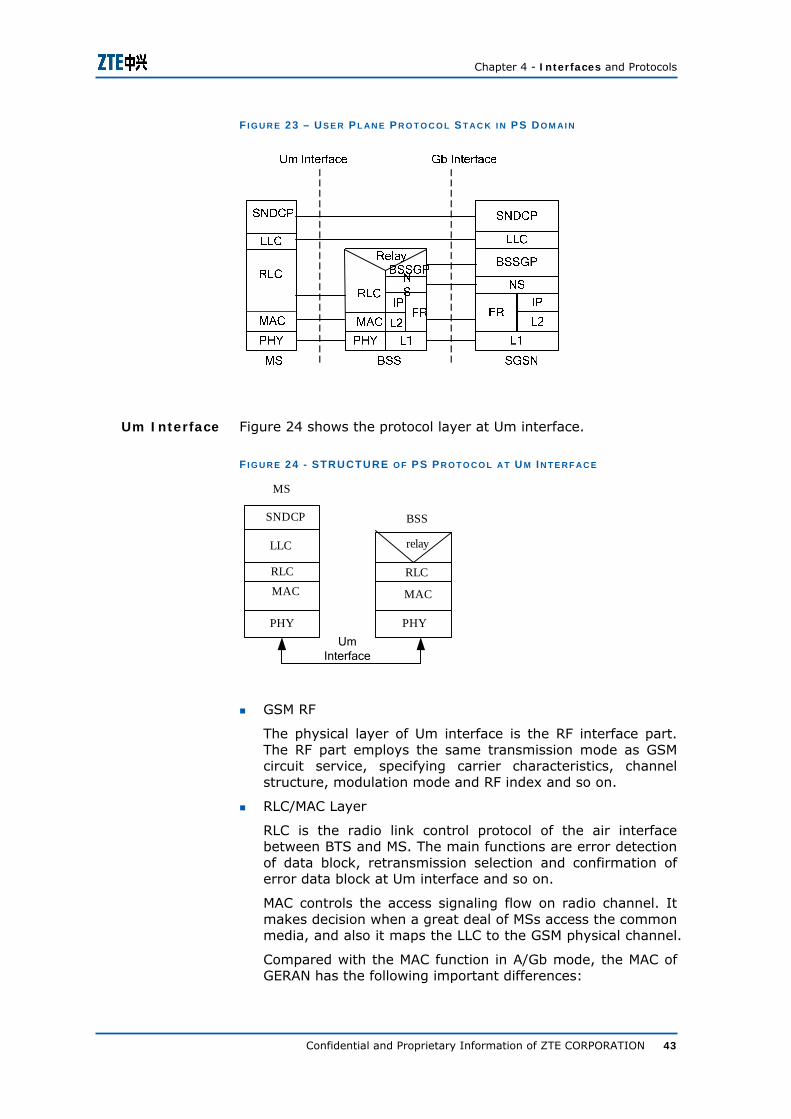
Chapter 4 - Interfaces and Protocols
Confidential and Proprietary Information of ZTE CORPORATION 43
F I G U R E 23 – U S E R P L AN E P R O T O C O L S T AC K I N PS D O M AI N
Figure 24 shows the protocol layer at Um interface.
F I G U R E 24 - STRUCTURE O F PS P R O T O C O L AT U M I N T E R F AC E
MS
Um 接口
BSS
RLC
MAC
relay
RLC
MAC
LLC
SNDCP
PHYPHYUm
Interface
GSM RF
The physical layer of Um interface is the RF interface part. The RF part employs the same transmission mode as GSM circuit service, specifying carrier characteristics, channel structure, modulation mode and RF index and so on.
RLC/MAC Layer
RLC is the radio link control protocol of the air interface between BTS and MS. The main functions are error detection of data block, retransmission selection and confirmation of error data block at Um interface and so on.
MAC controls the access signaling flow on radio channel. It makes decision when a great deal of MSs access the common media, and also it maps the LLC to the GSM physical channel.
Compared with the MAC function in A/Gb mode, the MAC of GERAN has the following important differences:
Um Interface

ZXG10 iBSC (V6.20) Base Station Controller Technical Manual
44 Confidential and Proprietary Information of ZTE CORPORATION
Supports one MAC entity with many TBF
Supports MAC layer encryption
LLC Layer
LLC is a radio link protocol based on HDLC, which can provide highly reliable encrypted logical link. LLC layer generates LLC address and frame filed from the SDDC data unit of upper layer SNDC layer for generating complete LLC frame. In addition, LLC can realize the one to many addressing and the retransmission control of data frame. LLC is independent from the bottom layer radio interface protocol for the least modification of NSS when introducing the other optional GPRS radio resolution. GSM04.64 standardizes LLC.
SNDCP
As the transition between network layer and data link layer, the main function of SNCDP is to packet the transmitted data and sent it to the LLC layer for transmission to find out the TCP/IP address and encryption method.
In SNDC layer, the transmitted data between MS and SGSN is divided into one or more SNDC data packet units. SNDC data packet unit is put into LLC frame after being generated.
Relay
Relay forwards the LLC PDU between Um and Gb interface.
Layer1 (Physical and Transmission Layer)
This layer employs 2 Mbps E1 cable or catory-5 network cable.
Network Service
Network service is based on frame relay, and it is used to transmit the upper layer BSSGP PDU.
BSSGP
In transmission platform, this protocol provides connectionless link to transmit data without confirmation between BSS and SGSN.
IP
It is the internet protocol defined in RFC 791, which is used for routing user data and control signaling. When it employs FE for transmission between iBSC and SGSN, the data link layer at Gb interface uses IP protocol.
FR
Frame relay provides permanent virtual circuit, which transmits the user data and signaling at Gb data. When it employs E1 for transmission between iBSC and SGSN, the data link layer at Gb interface uses FR protocol.
Gb Interface

Chapter 4 - Interfaces and Protocols
Confidential and Proprietary Information of ZTE CORPORATION 45
Control Plane Protocol Stack in PS Domain
Figure 25 shows the control plane protocol stack in PS domain.
F I G U R E 25 – C O N T R O L PL AN E S T AC K P R O T O C O L I N PS D O M AI N
GMM/SM implements GPRS mobility management and session management protocol processing, such as attach/detach, security management, route area update, location area update, and PDP context activation/deactivation.
For the details of the other layers, refer to User Plane Protocol Stack in PS Domain.
ZXG10 iBSC (V6.20) Base Station Controller Technical Manual
46 Confidential and Proprietary Information of ZTE CORPORATION
This page is intentionally blank.

Confidential and Proprietary Information of ZTE CORPORATION 47
C h a p t e r 5
Data Flow Direction
This chapter explains the following topics:
System Clock Signal Flow
User Plane Data Flow
Control Plane Data Flow
System Clock Signal Flow
Figure 26 shows the system clock signal flow of ZXG10 iBSC (V6.20).
F I G U R E 26 – S Y S T E M C L O C K S I G N AL FL O W

ZXG10 iBSC (V6.20) Base Station Controller Technical Manual
48 Confidential and Proprietary Information of ZTE CORPORATION
CLKG is responsible for following two functions:
CLKG board in the control unit of ZXG10 iBSC (V6.20) is responsible for providing the clock signals to other parts. CLKG takes the clock signal from A-interface. After synchronization, CLKG provides separate clock signals to resource unit and packet switching unit.
It provides clock signals to resource unit by the UIMU and packet switching unit through UIMC.
User Plane Data Flow
User plane data flow is divided in to following two parts:
User plane data flow in CS domain
User plane data flow in PS domain
Figure 27 shows the user plane data flow when TC is internal.
F I G U R E 27 – U S E R P L AN E D AT A FL O W I N CS D O M AI N (TC I S I N T E R N A L )
Taking uplink direction as an example, the downlink direction is opposite.
BIU detaches the user plane data and control plane data, sends the user plane data to TCU for processing. After the processing of TCU, the data is sent to AIU. The flow direction is 1→2.
Figure 28 shows the user plane data flow when TC is external.
User Plane Data Flow in
CS Domain

Chapter 5 - Data Flow Direction
Confidential and Proprietary Information of ZTE CORPORATION 49
F I G U R E 28 – U S E R P L AN E D AT A FL O W I N CS D O M AI N (TC I S E X T E R N AL )
Taking uplink direction as an example, the downlink direction is opposite.
BIU detaches the user plane data and control plane data, sends the user plane data to the Ater interface unit NSMU, and then sends it to iTC for processing.
Figure 29 shows the user plane data flow in PS domain.
F I G U R E 29 – U S E R P L AN E D AT A FL O W I N PS D O M AI N
Taking uplink direction as an example, the downlink direction is opposite.
The PCU frame detached by BIU interface is sent to UPU (i.e. UPPB) via user plane switching network and then the user data in PS domain is detached by UPPB for processing. After that, the data is sent to GIU via user plane switching network. The flow direction is 1→2.
User Plane Data Flow in
PS Domain

ZXG10 iBSC (V6.20) Base Station Controller Technical Manual
50 Confidential and Proprietary Information of ZTE CORPORATION
Control Plane Data Flow
Control plane data flow is divided in to following two parts:
Control plane data flow in CS domain
Control plane data flow in PS domain
Figure 30 shows the control plane data flow in CS domain when TC is internal:
F I G U R E 30 – C O N T R O L PL AN E D AT A FL O W I N CS D O M A I N (TC I S I N T E R N AL )
The description of diagram is as follows:
Abis interface signaling flow
BIU separate the user plane data and control plane signaling data.
BIU sends the control plane signaling data to CMP through the LAPD channel via the control switching network.
CMP process the control signaling data and send part of it back to the BIU directly, the data flow direction is 1→1.
The other part of signaling generates A interface signaling flow, which is sent to AIU. The flow direction is 1→2.
A-interface signaling flow
A-interface unit (AIU) performs the MTP2 processing and sends the control plane signaling data to the CMP for MTP3 processing via control plane switching network.
CMP perform the MTP3 processing and also send some data to the OMP for processing.
OMP send the process result to CMP. CMP send all the processed data to the AIU via the control plane switching network.
Control Plane Data Flow in
CS Domain

Chapter 5 - Data Flow Direction
Confidential and Proprietary Information of ZTE CORPORATION 51
Alternatively the control plane data flow direction can be from AIU to the CMP via the control plane switching network and vice versa.
The data flow direction is 2 → 3 → 3 → 2 or 2 → 2.
Figure 31 shows the control plane data flow in CS domain when TC is external:
F I G U R E 31 – C O N T R O L PL AN E D AT A FL O W I N CS D O M A I N (TC I S E X T E R N AL )
Abis interface signaling flow is the same as the case when TC is internal.
Ater interface control plane signaling is sent from CMP to NSMU, as shown in flow 2. It reaches iTC via NSMU. Some global processes involve OMP, as shown in flow 3.
A-interface control plane signaling is sent from CMP to NSMU, as shown in flow 2, and then sent to MSC via iTC.
Figure 32 shows the control plane data flow in PS domain.
F I G U R E 32 – C O N T R O L PL AN E D AT A FL O W I N PS D O M A I N
BIU
User Plane Switching NetworkAbis
Interface
AIU
A-Interfac
e
GIU
Gb Interfac
e1
4
Control Plane Switching Network
CMPOMP
6
UPU TCU
2
35
Control Plane Data Flow in
PS Domain

ZXG10 iBSC (V6.20) Base Station Controller Technical Manual
52 Confidential and Proprietary Information of ZTE CORPORATION
The description of diagram is as follows:
Abis interface signaling flow
BIU sends the control plane signaling data to the CMP for processing. CMP process and send back some immediate data (like immediate assignments) to BIU. The data flow direction is 1 → 1.
Control data of some users containing more assignments need to be sent to user plane/PCU processing unit via the control plane switching network. User plane/PCU processing unit process this data and send back to CMP. CMP transfer this data to BIU through the control plane switching network. The data flow direction is 1 → 3 → 3 → 1.
By LAPD board of Abis interface unit send user data (PACCH uplink channel request) to the user plane/PCU processing unit via the user plane switching network. Use plane/PCU processing unit send the control signaling data to CMP for processing. CMP process it and send back to user plane /PCU processing unit. At the end the user plane processing unit transfers back the processed data by user plane switching network to the BIU. The data flow direction is 2 → 3 → 3 → 2.
Gb interface signaling flow
PCU sends the control data to the corresponding board for processing, including CMP, OMP and UPPB. After the processing is finished, the data is sent to Gb interface via PCU, the data flow direction is 4 → 4, 5 → 5 or 6 → 6.

Confidential and Proprietary Information of ZTE CORPORATION 53
C h a p t e r 6
Networking Modes and System Configuration
This chapter contains the following topics:
Abis Interface Networking Modes
A-Interface Networking Mode
Ater Interface Networking Mode
Gb interface networking mode
Operation and Maintenance System Networking
Cabinet Configuration
Shelf Configuration
NM Configuration
Networking Modes There are interfaces on iBSC, NetNumen, BTS, MSC and SGSN. ZXG10 iBSC provides various networking modes at each interface. In actual practice, select the networking mode according to the environment flexibly. The following topics describes various networking modes supported by ZXG10 iBSC according to the four interfaces respectively.
Abis Interface Networking Modes
ZXG10 iBSC (V6.20) supports all series of ZXG10-BTS models and can configure corresponding BTS networking modes including star, chain, tree, and ring types. In practice, these modes are used in combination to achieve the best price-performance ratio.

ZXG10 iBSC (V6.20) Base Station Controller Technical Manual
54 Confidential and Proprietary Information of ZTE CORPORATION
Using E1 for Transmission
The configuration of star networking is shown in Figure 33.
F I G U R E 33 – AB I S I N T E R F AC E S T AR N E T W O R K I N G
iBSC
SITE0
SITE1
SITEn
.
.
.
Each site is directly connected to BSC in a star network. The networking mode is simple, links are reliable, and maintenance and construction is convenient. This mode is applicable in a densely populated region.
The configuration of chain networking is shown in Figure 34.
F I G U R E 34 – AB I S I N T E R F AC E C H AI N -N E T W O R K I N G
SITE0iBSC SITE1 SITE2
A chain network uses less transmission equipment as the sites are connected using the by-pass or straight through function. If a shallow depth BTS encounters any broken link, the cascaded BTS with deeper depth can be directly connected without affecting normal operation. This mode is applicable in regions with strip-shaped population distribution.
The configuration of tree networking is shown in Figure 35.
Star Networking
Chain Networking
Tree Networking

Chapter 6 - Networking Modes and System Configuration
Confidential and Proprietary Information of ZTE CORPORATION 55
F I G U R E 35 – AB I S I N T E R F AC E TR E E N E T W O R K I N G
iBSC
SITE0
S IT E 1
S IT E 2
S IT E n
.
.
.
Tree networking mode is more complex and signal passes through more nodes with low link reliability. Any fault in upper level site may affect the normal operation of a lower level site. This mode is applicable for large areas with sparse population but not frequently applied.
The configuration of ring networking is shown in Figure 36.
F I G U R E 36 – AB I S I N T E R F AC E R I N G N E T W O R K I N G
iBSC
SITE0
SITE2
SITE1
SITE3
Ring networking is the most useful and advanced networking mode in GSM communication structure. If any of site links is broken, the communication starts from the opposite way. This enhances the system performance and reliability. Due to ring
Ring Networking

ZXG10 iBSC (V6.20) Base Station Controller Technical Manual
56 Confidential and Proprietary Information of ZTE CORPORATION
networking mode the inter-site and iBSC communication becomes almost uninterruptible.
Using IP for Transmission
When use IP for transmission, the BTS accessing iBSC include macro cell BTS and micro cell BTS.
The typical application scenario of iBSC IP Abis is shown in Figure 37.
F I G U R E 37 – ZXG10 I BSC TY P I C AL IP AB I S AC C S E S S
MS
ADSL MODEM
ADSL MODEM
MSxDSL接入设备
MS
MS
MS
MS
Site1
Site2
MS
iBSCIP专
线
ZTE
宏蜂窝基站
INTERNET公网
Intranet企业网
微蜂窝基站
微蜂窝基站
微蜂窝基站
微蜂窝基站
微蜂窝基站
Micro Cell BTS
Macro Cell BTS
Micro Cell BTS
Micro Cell BTS
Micro Cell BTS
Micro Cell BTS
IP DedicatedCable
IntranetEnterprise Network
Internet PublicNetwork
xDSL Access Device
Generally, macro cell BTS access iBSC directly by IP dedicated cable.
Micro cell BTS access iBSC in many ways, including:
Access via internet from family by ADSL.
Access the internet via enterprise gateway by deploying the BTS inside the enterprise.
Access the iBSC via the IP dedicated cable of macro cell BTS.
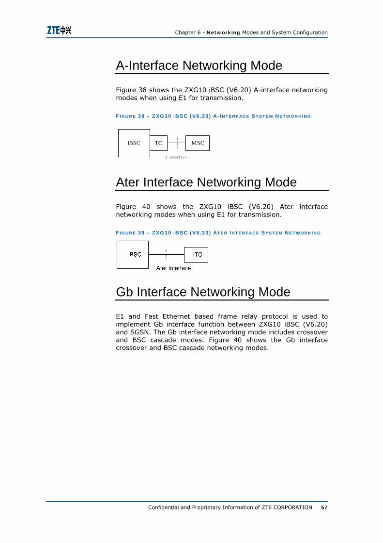
Chapter 6 - Networking Modes and System Configuration
Confidential and Proprietary Information of ZTE CORPORATION 57
A-Interface Networking Mode
Figure 38 shows the ZXG10 iBSC (V6.20) A-interface networking modes when using E1 for transmission.
F I G U R E 38 – ZXG10 I BSC (V6 .20 ) A- I N T E R F AC E S Y S T E M NE T W O R K I N G
iBSC TC
A接口
MSC
A Interface
Ater Interface Networking Mode
Figure 40 shows the ZXG10 iBSC (V6.20) Ater interface networking modes when using E1 for transmission.
F I G U R E 39 – ZXG10 I BSC (V6 .20 ) AT E R I N T E R F AC E S Y S T E M N E T W O R K I N G
Gb Interface Networking Mode
E1 and Fast Ethernet based frame relay protocol is used to implement Gb interface function between ZXG10 iBSC (V6.20) and SGSN. The Gb interface networking mode includes crossover and BSC cascade modes. Figure 40 shows the Gb interface crossover and BSC cascade networking modes.

ZXG10 iBSC (V6.20) Base Station Controller Technical Manual
58 Confidential and Proprietary Information of ZTE CORPORATION
F I G U R E 40 – ZXG10- I BSC (V 1 .0 ) GB I N T E R F AC E S Y S T E M N E T W O R K I N G
Multiple iBSCs can be cascaded and then connected to SGSN to save Gb interface line resources if bandwidth permits. The iBSC cascade mode is very convenient. For example, iBSC1 is directly connected to SGSN. iBSC2 can be directly connected to the other PCM ports of DTB via E1. A transparent transmission from iBSC2 to SGSN can be implemented via configuration, saving resource with no need for an E1 between iBSC2 and SGSN.
OMC Interface Networking
The ZXG10 iBSC O&M system contains Operation and Maintenance Module (OMM) and NetNumen M31. OMM is a part of iBSC and is used for operation and maintenance of iBSC. ZXG10 iBSC is connected with NetNumen M31 through OMM.
In ZXG10 iBSC (V6.20), OMM hardware platform uses SBCX board. SBCX uses primary & secondary configuration, adding the reliability for operation & maintenance module.
The hardware platform of OMM can be the SBCX board or the SUN server. The former adopts SBCX configuration while the latter adopts SVR+SUN server configuration.
ZXG10 iBSC (V6.20) supports two types of maintenance:
Local maintenance networking
ZXG10 iBSC interconnects NetNumen M31 through LAN.
Remote centralized maintenance networking
ZXG10 iBSC interconnects NetNumen M31 through DCN (including PCM and IP backbone network).

Chapter 6 - Networking Modes and System Configuration
Confidential and Proprietary Information of ZTE CORPORATION 59
It is the simplest and most common mode. In this mode, the iBSC and NetNumen M31 are located on the same LAN and connected via Ethernet. NetNumen M31 and the iBSCs it manages are physically present in the same location, and they are connected by LAN.
Figure 41 shows the local maintenance networking when ZXG10 iBSC adopts the SBCX configuration. In this case, the OMP1 port (it is recommended to set the IP address within network segment 129) on the rear board of SBCX is connected with OMP and LMT through LAN Switch. The user performs operation and maintenance through the LMT terminal. The OMC1 port (it is recommended to set the IP address within network segment 10) on the rear board of SBCX is connected with the NetNumen M31 server through LAN Switch, realizing accessing the network management system.
F I G U R E 41 – IBSC LO C AL O P E R AT I O N & M AI N T E N AN C E (SBCX C O N F I G U R AT I O N )
In the PCM networking mode for remote centralized maintenance, the 2 Mbps PCM link (A-interface E1) available between MSC and the iBSC or other dedicated PCM links can be used to transmit NM information. In this mode, the timeslot in PCM link is borrowed to transmit operation and maintenance information at a rate of n x 64 kbps (n is the number of occupied timeslots). PCM equipment is used to extract a certain number of timeslots from the PCM links for operation and maintenance. This approach is economical, practical, and fully utilizes available
Local Maintenance Networking
Remote Centralized
Maintenance Networking
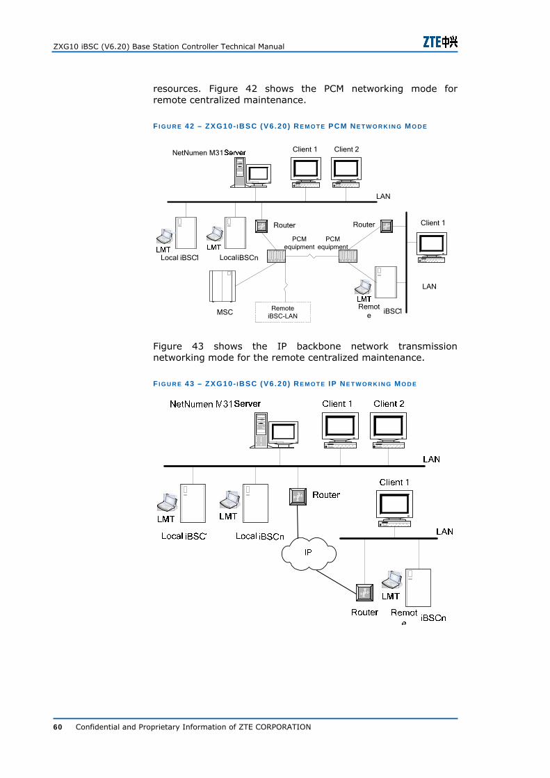
ZXG10 iBSC (V6.20) Base Station Controller Technical Manual
60 Confidential and Proprietary Information of ZTE CORPORATION
resources. Figure 42 shows the PCM networking mode for remote centralized maintenance.
F I G U R E 42 – ZXG10- I BSC (V6 .20 ) R E M O T E PCM NE T W O R K I N G M O D E
PCM equipment
Router
MSCRemot
eiBSC1
LAN
NetNumen M31 Client 1 Client 2
Local iBSC1 iBSCn
LAN
Local
Client 1Router
PCM equipment
RemoteiBSC-LAN
Figure 43 shows the IP backbone network transmission networking mode for the remote centralized maintenance.
F I G U R E 43 – ZXG10- I BSC (V6 .20 ) R E M O T E IP NE T W O R K I N G M O D E

Chapter 6 - Networking Modes and System Configuration
Confidential and Proprietary Information of ZTE CORPORATION 61
System Configuration In ZXG10 iBSC system, two resource shelves form a Resources board Configuration Basal Unit (RCBU). It only needs to add RCBU for capacity expansion.
Equipment configuration
Configuration Principle
1. Resource shelf / gigabyte resource shelf includes AIU, BIU, TCU, PCU units, and boards include DTB, SDTB/SDTB2, GUP/GUP2, UIMU/GUIM, GIPI, and EIPI. When system is expanded, capacity can be expanded by adding resource shelf / gigabyte shelf to configure more resource board.
2. Board of control shelf includes CMP, SBCX, UIMC, OMP, CLKG, and CHUB.
3. Board of switching shelf includes GLI, PSN, CMP, and UIMC.
Dual cabinet configuration
When cabinet configures resource shelf and gigabyte resource shelf, different shelf positions for dual cabinet is shown in Figure 44 and Figure 45.
F I G U R E 44 - DU AL C AB I N E T C O N F I G U R AT I O N W H I L E C O N F I G U R I N G R E S O U R C E S H E L F
分组交换框
层1
1号机柜(主机柜) 2号机柜
资源框
控制框
资源框
资源框
资源框
资源框
资源框
层4
层3
层2
No. 1 Cabinet (Primary) No. 2 Cabinet
L1
L2
L3
L4
Resource Shelf
Resource Shelf
Resource Shelf
Resource Shelf
Resource Shelf
Resource Shelf
Control Shelf
Packet switching shelf

ZXG10 iBSC (V6.20) Base Station Controller Technical Manual
62 Confidential and Proprietary Information of ZTE CORPORATION
F I G U R E 45 - DU AL C AB I N E T C O N F I G U R AT I O N W H I L E C O N F I G U R I N G GB R E S O U R C E S H E L F
分组交换框
层1
1号机柜(主机柜) 2号机柜
资源框
控制框
资源框
资源框
资源框
资源框
资源框
层4
层3
层2
No. 1 Cabinet (Primary) No. 2 Cabinet
L1
L2
L3
L4
GB Resource Shelf
GB Resource Shelf
GB Resource Shelf
GB Resource Shelf
GB Resource Shelf
GB Resource Shelf
Control Shelf
Packet switching shelf
Dual cabinet configuration is shown in Table 18
T AB L E 18 - C AB I N E T C O N F I G U R AT I O N D E S C R I P T I O N
Shelf Name Whether Necessary Position in the Cabinet
Control Shelf Necessary Position fixed, located in shelf 2, cabinet 1
Packet Switching Shelf
Necessary Position fixed, located in shelf 4, cabinet 1
Resource Shelf/GB resource shelf
As required layer 1 or layer 3 in cabinet 1, any layer in cabinet 2
Fully configured dual cabinet capacity description is given in Table 19.
T AB L E 19 – DU AL C AB I N E T C AP AC I T Y D E S C R I P T I O N
Parameter Name Value
Number of carriers supported 3072
E1 256 Flow at Gb interface (Mbps) IP 400
E1 624 pieces
IP 2 pairs of GE Abis interface capacity
IPoE 480 pieces
E1 at Abis interface 184 pieces Ater interface E1 IP at Abis interface 176 pieces
Typical configuration
1. While configuring resource shelf
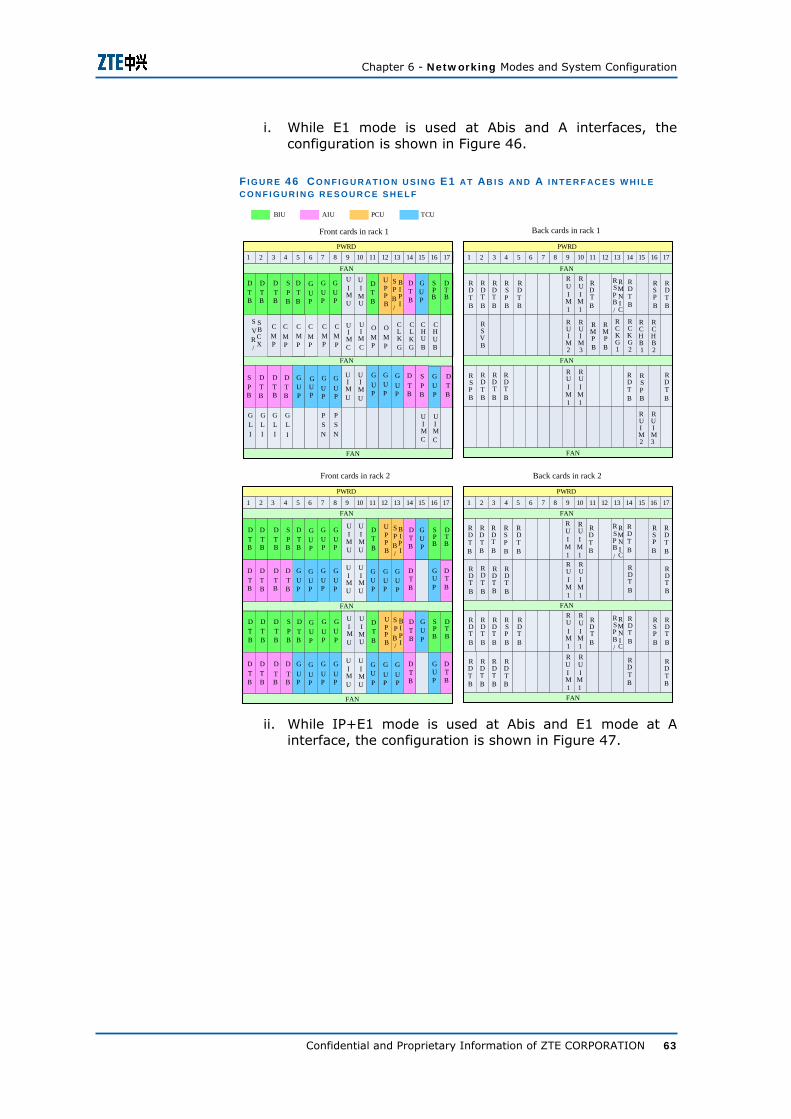
Chapter 6 - Networking Modes and System Configuration
Confidential and Proprietary Information of ZTE CORPORATION 63
i. While E1 mode is used at Abis and A interfaces, the configuration is shown in Figure 46.
F I G U R E 46 CO N F I G U R AT I O N U S I N G E1 AT AB I S AN D A I N T E R F AC E S W H I L E C O N F I G U R I N G R E S O U R C E S H E L F
1 2 3 4 5 6 7 8 9 10 11 12 13 14 15 16 17PWRD
FAN
FAN
FAN
机架2前插卡 机架2后插卡
1 2 3 4 5 6 7 8 9 10 11 12 13 14 15 16 17PWRD
FAN
FAN
FAN
UIMU
UI
MU
1 2 3 4 5 6 7 8 9 10 11 12 13 14 15 16 17PWRD
FAN
GLI
GLI
GLI
GLI
FAN
FAN
机架1前插卡 机架1后插卡
1 2 3 4 5 6 7 8 9 10 11 12 13 14 15 16 17PWRD
FAN
FAN
FAN
RUI
M2
RUIM3
DTB
SPB
DTB
GUP
GUP
DTB
GUP
SPB
DTB
CMP
CMP
UIMC
UI
MC
CHU
CHU
OMP
OMP B B
CLK
CLK
G G
RSPB
GUP
UIM
UIM
DTB
GUP U U
GUP
GUP
GUP
GUP
GUP
DTB
PSN
PSN
UIM
UIM
C C
RUIM2
RUIM3
RDTB
RDTB
RDTB
RDTB
RMP
RMP
B B
RCKG1
RCKG2
RCHB1
RCHB2
RDTB
RDT
RSP
B B
RDTB
RSP
RDT
B B
BIU AIU PCU TCU
RUI
M
RUI
M1 1
RUI
M
RUI
M1 1
DTB
DTB
GUP
SPB
BIPI/
UPPB
DTB
CMP
CMP
CMP
CMP
SVR
SBCX/
DTB
SPB
DTB
DTB
SPB
GUP
RDTB
RDTB
RSVB
RDTB
RDTB
RSPB
UI
MU
UIMU
DTB
SPB
DTB
GUP
GUP
DTB
GUP
SPB
DTB
DTB
DTB
GUP
SPB
BIPI
UPPB
DTB
/
UIMU
UI
MU
DTB
SPB
DTB
GUP
GUP
DTB
GUP
SPB
DTB
DTB
DTB
GUP
SPB
BIPI
UPPB
DTB
/
UIMU
UIMU
DTB
DTB
GUP
GUP
GUP
DTB
GUP
DTB
DTB
DTB
GUP
GUP
GUP
GUP
UIMU
UIMU
DTB
DTB
GUP
GUP
GUP
DTB
GUP
DTB
DTB
DTB
GUP
GUP
GUP
GUP
RDTB
RDTB
RDT
RSP
B B
RDTB
RSP
RDT
B B
RUI
M
RUI
M1 1
RDTB
RDTB
RDTB
RDTB
RDT
RSP
B B
RDTB
RSP
RDT
B B
RUI
M
RUI
M1 1
RDTB
RDTB
RDTB
RDT
RDT
B B
RDTB
RDTB
RUI
M
RUI
M1 1
RDTB
RDTB
RDT
RDT
B B
RDTB
RDTB
RUIM
RUI
M1 1
RDTB
RSPB
RMNI
/ C
RSPB
RMNI
/ C
RSPB
RMNI
/ C
Front cards in rack 1 Back cards in rack 1
Front cards in rack 2 Back cards in rack 2
ii. While IP+E1 mode is used at Abis and E1 mode at A interface, the configuration is shown in Figure 47.

ZXG10 iBSC (V6.20) Base Station Controller Technical Manual
64 Confidential and Proprietary Information of ZTE CORPORATION
F I G U R E 47 - CO N F I G U R AT I O N U S I N G IP+E1 AT AB I S AN D E1 AT A I N T E R F AC E W H I L E C O N F I G U R I N G R E S O U R C E S H E L F
1 2 3 4 5 6 7 8 9 10 11 12 13 14 15 16 17PWRD
FAN
FAN
FAN
机架2前插卡 机架2后插卡
1 2 3 4 5 6 7 8 9 10 11 12 13 14 15 16 17PWRD
FAN
FAN
FAN
UIMU
UI
MU
1 2 3 4 5 6 7 8 9 10 11 12 13 14 15 16 17PWRD
FAN
GLI
GLI
GLI
GLI
FAN
FAN
机架1前插卡 机架1后插卡
1 2 3 4 5 6 7 8 9 10 11 12 13 14 15 16 17PWRD
FAN
FAN
FAN
RUI
M2
RUIM3
GUP
DTB
GUP
DTB
GUP
SPB
GUP
CMP
CMP
UIMC
UI
MC
CHU
CHU
OMP
OMP B B
CLK
CLK
G G
RSPB
GUP
UIM
UIM
DTB
GUP U U
GUP
GUP
GUP
GUP
GUP
DTB
PSN
PSN
UIM
UIM
C C
RUIM2
RUIM3
RDTB
RDTB
RDTB
RMP
RMP
B B
RCKG1
RCKG2
RCHB1
RCHB2
RDTB
RDTB
RDTB
RSPB
BIU AIU PCU TCU
RUI
M
RUI
M1 1
RUI
M
RUI
M1 1
DTB
DTB
GUP
SPB
BIPI/
UPPB
GUP
CMP
CMP
CMP
CMP
SVR
SBCX/
DTB
SPB
DTB
DTB
SPB
GUP
RDTB
RSPB
RMNI
/
RSVB
RDTB
RDTB
RSPB
UI
MU
UIMU
DTB
SPB
DTB
GUP
GUP
DTB
GUP
SPB
DTB
DTB
DTB
GUP
SPB
BIPI
UPPB
DTB
/
UIMU
UI
MU
DTB
GUP
GUP
GUP
GUP
GUP
GUP
GUP
GUP
DTB
DTB
GUP
BIPI
GUP
UIMU
UIMU
DTB
DTB
GUP
GUP
GUP
DTB
GUP
DTB
DTB
DTB
GUP
GUP
GUP
GUP
UIMU
UIMU
DTB
DTB
SPB
GUP
GUP
GUP
DTB
DTB
SPB
GUP
GUP
RDTB
RDTB
RDT
RSP
B B
RDTB
RSP
RDT
B B
RUI
M
RUI
M1 1
RDTB
RDTB
RDTB
RDTB
RUI
M
RUI
M1 1
RDTB
RDTB
RDT
RDT
B B
RDTB
RDTB
RUI
M
RUI
M1 1
RDTB
RDTB
RDT
RDT
B B
RSPB
RUIM
RUI
M1 1
RDTB
BIPI
BIPI
RMNI
RMNI
C C C
RSPB
RMNI
/ C
RSPB
RMNI
/ C
BIPI
UPPB
SPB
BIPI/
UPPB
UPPB
RMNI
RMNI
C C
RSPB
Front cards in rack 1 Back cards in rack 1
Back cards in rack 2Front cards in rack 2
2. While configuring gigabyte resource shelf
i. While E1 mode is used at Abis and A interfaces, the configuration is shown in Figure 48.

Chapter 6 - Networking Modes and System Configuration
Confidential and Proprietary Information of ZTE CORPORATION 65
F I G U R E 48 - CO N F I G U R AT I O N U S I N G E1 AT AB I S AN D A I N T E R F AC E S W H I L E C O N F I G U R I N G R E S O U R C E S H E L F
GUIM
GUIM
1 2 3 4 5 6 7 8 9 10 11 12 13 14 15 16 17PWRD
FAN
FAN
FAN
机架2前插卡 机架2后插卡
1 2 3 4 5 6 7 8 9 10 11 12 13 14 15 16 17PWRD
FAN
FAN
FAN
SPB
GUP
DTB
DTB2 2
DTB
GUP
DTB
DTB2
GUP
SPB
2 2
DTB
DTB
GUIM
GUI
M
DTB
SPB
GUP
2 2
RSPB
GUP2
GUI
GUI
DTB
DTB M M
DTB
DTB
SPB
DTB
2
GUP2
SPB2
RDT
RDT
B
B
RDT
RDT
B B
RDT
RDT
B B
RDTB
RSPB
RSPB
RDTB
RDTB
RSPB
RDT
RDT
B B
RDT
RDT
B B
RSP
RSP
B B
RSPB
DTB
SPB2
SPB2
SPB2
GUP
GUP
2 2
DTB
DTB
GUP2
DTB
DTB
GUP2
DTB
DTB
GUP
GUP
2 2
DTB
SPB2
DTB
DTB
GUIM
GUIM
DTB
GUP
GUP
2 2
DTB
DTB
GUP2
DTB
DTB
GUP2
DTB
DTB
GUP
GUP
2 2
RDT
RSP
B B
RDTB
RDTB
RDTB
RDT
RDT
B B
RDTB
RDTB
RDTB
RDTB
RDTB
RDTB
RDTB
RDT
RDT
B B
RDTB
RDTB
RSPB
GUIM
GUIM
1 2 3 4 5 6 7 8 9 10 11 12 13 14 15 16 17PWRD
FAN
GLI
GLI
GLI
GLI
FAN
FAN
机架1前插卡 机架1后插卡
1 2 3 4 5 6 7 8 9 10 11 12 13 14 15 16 17PWRD
FAN
FAN
FAN
RUI
M2
RUIM3
SPB
GUP
DTB
DTB2 2
DTB
GUP
DTB
DTB
2
SPB
DTB
DTB2
GUP
SPB
SPB
2 2 2
GIPI
/
SPB2
GIPI
/
CMP
CMP
CMP
CMP
UIMC
SBCX
SBCX
UI
MC
CHU
CHU
OMP
OMP B B
CLK
CLK
G G
SPB
GUP
2 2
RSP
GUP
B2
GUP2
GUI
GUI
DTB
DTB M M
DTB
DTB
GUP
DTB
2
DTB
DTB
GUP
GUP
2 2
SPB2
GLI
GLI
PSN
PSN
CMP
CMP
UIM
UIM
C C
RUIM2
RUIM3
RSV
RDT
B
B
RDT
RDT
B B
RDT
RDT
B B
RDTB
RDT
RDT
B B
RSPB
RSVB
RMP
RMP
B B
RCKG1
RCKG2
RCHB1
RCHB2
RSPB
RDT
RDT
B B
RDT
RDT
B B
RSPB
RGER
/
RSPB
RGER
/
RDT
RDT
B B
RSP
RSP
B B
BIU AIU PCU TCU
RGUM
RGUM
1 2
RGUM
RGUM
1 2
RGUM
RGUM
1 2RGUM
RGUM
1 2
RGUM
RGUM
1 2RGUM
RGUM
1 2
Front cards in rack 1 Back cards in rack 1
Front cards in rack 2 Back cards in rack 2
ii. While IP mode is used at Abis and A interfaces, the configuration is shown in Figure 49.

ZXG10 iBSC (V6.20) Base Station Controller Technical Manual
66 Confidential and Proprietary Information of ZTE CORPORATION
F I G U R E 49 - CO N F I G U R AT I O N U S I N G IP AT AB I S AN D A I N T E R F AC E S W H I L E C O N F I G U R I N G GB R E S O U R C E S H E L F
GUIM
GUIM
1 2 3 4 5 6 7 8 9 10 11 12 13 14 15 16 17PWRD
FAN
FAN
FAN
机架2前插卡 机架2后插卡
1 2 3 4 5 6 7 8 9 10 11 12 13 14 15 16 17PWRD
FAN
FAN
FAN
RGER
GUIM
GUIM
1 2 3 4 5 6 7 8 9 10 11 12 13 14 15 16 17PWRD
FAN
GLI
GLI
GLI
GLI
FAN
FAN
机架1前插卡 机架1后插卡
1 2 3 4 5 6 7 8 9 10 11 12 13 14 15 16 17PWRD
FAN
FAN
FAN
RGUM
RGUM
RUI
M2
RUIM3
GIP
GIP
I I
GUP2
GUP
GUP
2 2
CMP
CMP
CMP
CMP
UIMC
SBCX
SBCX
UI
MC
CHU
CHU
OMP
OMP B B
CLK
CLK
G G
GIP
GIP
I I
RGE
GIP
RI
GUP2
GUI
GUI
M M
GIPI
GUP
GUP
2 2
PSN
PSN
CMP
CMP
UIM
UIM
C C
RUIM2
RUIM3
RSVB
RGER 1 2
RSVB
RMP
RMP
B B
RCKG1
RCKG2
RCHB1
RCHB2
RGER
RGUM
RGUM
1 2
RGE
RGE
R R
BIU AIU PCU TCU
GUP
GUP
2 2
GUP2
GUP2
GUP
GUP
2 2
GIP
GIP
I I
CMP
CMP
GIPI
GUP2
GUP
GUP
2 2
GUP
GUP
2 2
GIPI
RGER
RGUM
RGUM
1 2
RGER
RGER
RGER
RGER
GIP
GIP
I I
GUP
GUP
2 2
GUP2
RGER
Front cards in rack 1 Back cards in rack 1
Front cards in rack 2 Back cards in rack 2
NM Configuration
Table 20 shows the hardware configuration of SBCX board.
T AB L E 20 – HAR D W AR E C O N F I G U R AT I O N O F SBCX B O AR D
Name Configuration
CPU Two Intel(R) Xeon 2G dual-core CPUs
Memory 4 GB
One 40 GB SATA hard disk Hard Disk
Two 146 GB SAS hard disks; RAID1 mirror
Two GE interfaces External Network Interface Two FE interfaces
Serial Port One RS232 serial port
SBCX Configuration

Chapter 6 - Networking Modes and System Configuration
Confidential and Proprietary Information of ZTE CORPORATION 67
Name Configuration
USB Interface
Two at the front and two at the back
Table 21 shows the hardware configuration of the client.
T AB L E 21 – HAR D W AR E C O N F I G U R AT I O N O F C L I E N T
Name Configuration
CPU Intel P4 or above, Intel Core2
Memory 1 GB or above
Hard Disk 80 GB or above
Client Configuration

ZXG10 iBSC (V6.20) Base Station Controller Technical Manual
68 Confidential and Proprietary Information of ZTE CORPORATION
This page is intentionally blank.

Confidential and Proprietary Information of ZTE CORPORATION 69
A p p e n d i x A
Abbreviations
Abbreviation Full Name
A
Abis A-bis Interface
APB ATM Process Board
AMP Application Manage Process
AMR Adaptive Multi –Rate
AMREN Adaptive Multi Rate Encoding
AMRFR Adaptive Multi Rate Full Rate
AMRHR Adaptive Multi Rate Half Rate
B
BCSN Backplane of Circuit Switch Network
BPSN Back Plane of Packet Switching Network
BCCH Broadcast Control Channel
BUSN Backplane of Universal Switch Network
BCTC Backplane of Control Centre
BIE Base station Interface Equipment
BIPP Abis Interface Peripheral Processor
BIU Abis Interface Unit
BNET Backplane of Network Layer
BOSN Bit Oriented Switching Network
BPCU Packet Control Unit Shelf
BRP BSSGP RLC/MAC Protocol
BSC Base Station Controller
BSMU Sub-multiplexing Interface Unit
BSS Base Station Subsystem
BSSAP Base Station Subsystem Application Part
BSSGP Base Station Subsystem GPRS Protocol
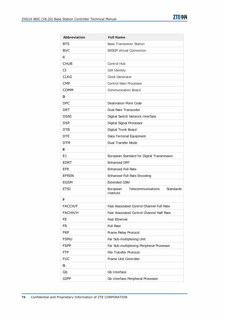
ZXG10 iBSC (V6.20) Base Station Controller Technical Manual
70 Confidential and Proprietary Information of ZTE CORPORATION
Abbreviation Full Name
BTS Base Transceiver Station
BVC BSSGP Virtual Connection.
C
CHUB Control Hub
CI Cell Identity
CLKG Clock Generator
CMP Control Main Processor
COMM Communication Board
D
DPC Destination Point Code
DRT Dual Rate Transcoder
DSNI Digital Switch Network Interface
DSP Digital Signal Processor
DTB Digital Trunk Board
DTE Data Terminal Equipment
DTM Dual Transfer Mode
E
E1 European Standard for Digital Transmission
EDRT Enhanced DRT
EFR Enhanced Full Rate
EFREN Enhanced Full Rate Encoding
EGSM Extended GSM
ETSI European Telecommunications Standards Institute
F
FACCH/F Fast Associated Control Channel Full Rate
FACHH/H Fast Associated Control Channel Half Rate
FE Fast Ethernet
FR Full Rate
FRP Frame Relay Protocol
FSMU Far Sub-multiplexing Unit
FSPP Far Sub-multiplexing Peripheral Processor
FTP File Transfer Protocol.
FUC Frame Unit Controller
G
Gb Gb Interface
GIPP Gb Interface Peripheral Processor
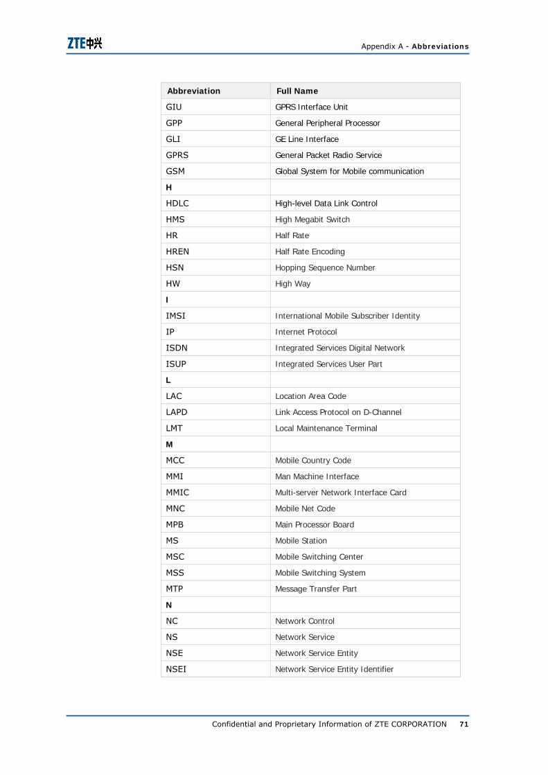
Appendix A - Abbreviations
Confidential and Proprietary Information of ZTE CORPORATION 71
Abbreviation Full Name
GIU GPRS Interface Unit
GPP General Peripheral Processor
GLI GE Line Interface
GPRS General Packet Radio Service
GSM Global System for Mobile communication
H
HDLC High-level Data Link Control
HMS High Megabit Switch
HR Half Rate
HREN Half Rate Encoding
HSN Hopping Sequence Number
HW High Way
I
IMSI International Mobile Subscriber Identity
IP Internet Protocol
ISDN Integrated Services Digital Network
ISUP Integrated Services User Part
L
LAC Location Area Code
LAPD Link Access Protocol on D-Channel
LMT Local Maintenance Terminal
M
MCC Mobile Country Code
MMI Man Machine Interface
MMIC Multi-server Network Interface Card
MNC Mobile Net Code
MPB Main Processor Board
MS Mobile Station
MSC Mobile Switching Center
MSS Mobile Switching System
MTP Message Transfer Part
N
NC Network Control
NS Network Service
NSE Network Service Entity
NSEI Network Service Entity Identifier

ZXG10 iBSC (V6.20) Base Station Controller Technical Manual
72 Confidential and Proprietary Information of ZTE CORPORATION
Abbreviation Full Name
NSMU Near Sub-multiplexing Unit
NSPP Near Sub-multiplexing Peripheral Processor
NSVC Network Service Virtual Connection
NSVCI Network Service Virtual Connection Identifier
O
OMP Operation & Maintenance Processor
OMCR Operation & Maintenance Center Radio
OPC Operating Point Code
OSI Open System Interconnection
P
PDP Packet Data Protocol
R
RPB Router Protocol Process Board
RCKG2 Rare Board 2 of CLKG
RCHB Rare Board of CHB
RPSN Rare Board of PSN
S
SACCH Slow Associated Control Channel
SCCP Signaling Connection Control Part
SDCCH Stand-alone Dedicated Control Channel
SLC Signaling Link Code
SGSN Serving GPRS Support Node.
SDTB Sonnet Digital Trunk Board
SPB Signaling Process Board
SMS Short Message Service
SMP Signaling Main Processor
SS7 Signaling System 7
STD Subscriber Trunk Dialing
SYCK Synchronous Clock Board
T
TFI TDM Fiber Interface
TC Transcoder
TSNB TDM Switch Network Board
TCH/F Traffic Channel Full Rate
TCH/H Traffic Channel Half Rate
TCP Transmission Control Protocol

Appendix A - Abbreviations
Confidential and Proprietary Information of ZTE CORPORATION 73
Abbreviation Full Name
TCPP Transcoder Unit Peripheral Processor
TCU Transcoder and Rate Adaptation Unit
TDMA Time Division Multiple Access
TIC Trunk Interface Circuit
TRAU Transcoder and Rate Adaptor Unit
TRX Transceiver
TS Time Slot
U
UIM Universal Interface Module
V
VTD Voice Transcoder Card
VTCD Voice Transcoder Card (DSP)
W
WPB Wireless Protocol Process Board

ZXG10 iBSC (V6.20) Base Station Controller Technical Manual
74 Confidential and Proprietary Information of ZTE CORPORATION
This page is intentionally blank.

Confidential and Proprietary Information of ZTE CORPORATION 75
A p p e n d i x B
Figures
Figure 1 – Position of iBSC in the Network (TC is Internal)........2
Figure 2 – Position of iBSC in the Network (TC is External) .......2
Figure 3 - ZXG10 iBSC effect diagram ...................................3
Figure 4 - Cabinet Layout schematic diagram .........................4
Figure 5 – Physical Structure of ZXG10 iBSC (V6.20)............. 18
Figure 6 – ZXG10 iBSC (V6.20) Hardware System Diagram .... 24
Figure 7 - ZXG10 iBSC Software Structure ........................... 28
Figure 8 – Foreground Software System Structure ................ 28
Figure 9 – External Interfaces of ZXG10 iBSC (TC is Internal) . 31
Figure 10 – External Interfaces of ZXG10 iBSC (TC is External)..................................................................................... 32
Figure 11 – User Plane Protocol Stack in CS Domain under E1 transmission mode ........................................................... 35
Figure 12 - User plane protocol stack in CS domain at Abis interface under IP transmission .......................................... 36
Figure 13 - User plane protocol stack in CS domain at A interface under IP transmission ....................................................... 36
Figure 14 - User plane protocol stack in CS domain at Abis interface under IPoE transmission ....................................... 37
Figure 15 – Control Plane Protocol Stack in CS Domain .......... 37
Figure 16 – Circuit Service Protocol Stack Structure at Um Interface ......................................................................... 38
Figure 17 –Control Plane Protocol stack at Abis Interface in CS domain under E1 or STM-1 transmisison mode ..................... 39
Figure 18 – Control plane protocol stack in CS domain at Abis interface under IP transmission .......................................... 39
Figure 19 – control plane protocol stack in CS domain at Abis interface under IPoe transmission ....................................... 40
ZXG10 iBSC (V6.20) Base Station Controller Technical Manual
76 Confidential and Proprietary Information of ZTE CORPORATION
Figure 20 –Structure of Control Plane Protocol stack in CS Domain at A-Interface....................................................... 40
Figure 21 - control plane protocol stack in CS domain at A interface Under IP transmission mode ................................. 41
Figure 22 – STRUCTURE of Control Plane Protocol stack in CS Domain at Ater Interface ................................................... 42
Figure 23 – User Plane Protocol Stack in PS Domain .............. 43
Figure 24 - STRUCTURE of PS Protocol at Um Interface.......... 43
Figure 25 – Control Plane Stack Protocol in PS Domain .......... 45
Figure 26 – System Clock Signal Flow ................................. 47
Figure 27 – User Plane Data Flow in CS Domain (TC is Internal)..................................................................................... 48
Figure 28 – User Plane Data Flow in CS Domain (TC is External)..................................................................................... 49
Figure 29 – User Plane Data Flow in PS Domain .................... 49
Figure 30 – Control Plane Data Flow in CS Domain (TC is Internal) ......................................................................... 50
Figure 31 – Control Plane Data Flow in CS Domain (TC is External)......................................................................... 51
Figure 32 – Control Plane Data Flow in PS Domain ................ 51
Figure 33 – Abis Interface Star Networking .......................... 54
Figure 34 – Abis Interface Chain-Networking ........................ 54
Figure 35 – Abis Interface Tree Networking.......................... 55
Figure 36 – Abis Interface Ring Networking .......................... 55
Figure 37 – ZXG10 iBSC Typical IP Abis Accsess ................... 56
Figure 38 – ZXG10 iBSC (V6.20) A-Interface System Networking..................................................................................... 57
Figure 39 – ZXG10 iBSC (V6.20) Ater Interface System Networking...................................................................... 57
Figure 40 – ZXG10-iBSC (V 1.0) Gb Interface System Networking...................................................................... 58
Figure 41 –iBSC Local operation & Maintenance (SBCX Configuration).................................................................. 59
Figure 42 – ZXG10-iBSC (V6.20) Remote PCM Networking Mode..................................................................................... 60
Figure 43 – ZXG10-iBSC (V6.20) Remote IP Networking Mode 60
Figure 44 - Dual cabinet configuration while configuring resource shelf............................................................................... 61
Figure 45 - Dual cabinet configuration while configuring GB resource shelf .................................................................. 62

Appendix B - Figures
Confidential and Proprietary Information of ZTE CORPORATION 77
Figure 46 Configuration using E1 at Abis and A interfaces while configuring resource shelf.................................................. 63
Figure 47 - Configuration using IP+E1 at Abis and IP at A interface while configuring resource shelf............................. 64
Figure 48 - Configuration using E1 at Abis and A interfaces while configuring resource shelf.................................................. 65
Figure 49 - Configuration using IP at Abis and A interfaces while configuring GB resource shelf ............................................. 66

ZXG10 iBSC (V6.20) Base Station Controller Technical Manual
78 Confidential and Proprietary Information of ZTE CORPORATION
This page is intentionally blank.

Confidential and Proprietary Information of ZTE CORPORATION 79
Tables
Table 1 – Manual Summary ..................................................i
Table 2 – Typographical Conventions.................................... iii
Table 3 – Mouse Operation Conventions ............................... iv
Table 4 – Usage Explanation of the Hazardous Substances in ZXG10 iBSC (V6.20) ...........................................................v
Table 6 – Weight of iBSC Cabinet........................................ 18
Table 7 – Power Supply Range ........................................... 18
Table 8 – Power Consumption of ZXG10 iBSC (V6.20) ........... 19
Table 9 – Grounding Requirements of ZXG10 iBSC (V6.20)..... 19
Table 10 – Temperature and Humidity Requirements for iBSC(V6.20) .................................................................... 19
Table 11 – Air Pollution and Atmospheric Pressure Requirements..................................................................................... 19
Table 12 – Clock Indices of ZXG10 iBSC (V6.20) ................... 20
Table 13 – Reliability Indices of ZG10 iBSC (V6.20)............... 20
Table 14 - Table ZXG10 iBSC Interface Types....................... 21
Table 15 - Capacity Index of A & Abis interface during full configuration of the system................................................ 21
Table 16 – Shelves Description........................................... 25
Table 17 – ZXG10 iBSC (V6.20) Boards List ......................... 25
Table 18 – Functional Description of ZXG10 iBSC External Interfaces........................................................................ 32
Table 19 - Cabinet Configuration Description ........................ 62
Table 20 – Dual Cabinet Capacity Description ...................... 62
Table 21 – Hardware Configuration of SBCX Board ................ 66
Table 22 – Hardware Configuration of Client......................... 67

ZXG10 iBSC (V6.20) Base Station Controller Technical Manual
80 Confidential and Proprietary Information of ZTE CORPORATION
This page is intentionally blank.

Confidential and Proprietary Information of ZTE CORPORATION 81
Index
A interface networking modes....................................61
BSC cascade networking modes....................................61
chain network.....................58 chain networking ................58 clock indices.......................22 development standards........14 DTM..................................10 grounding requirements .......21 Interface Types...................22 Operating temperature ........21
Physical indices .................. 19 Relative humidity................ 21 Reliability indices ................ 22 ring networking .................. 59 Software system................. 32 star network ...................... 58 star networking .................. 58 Tree network...................... 59 Voltage ............................. 20 Voltage fluctuation.............. 20 ZXG10 iBSC ................. 3, v, vi ZXG10 iBSC (V6.20)..............3