simple design tools for piled raft foundations
DESCRIPTION
Simple Design Tools for Piled Raft FoundationsTRANSCRIPT

Simple design tools for piled raft foundations
P. CLANCY� and M. F. RANDOLPH�
The design of piled raft foundations is ham-pered by the complex interaction effects whichtake place between the piles and the raft.Although the ®nite element method and theboundary element method have been used toaccount explicitly for the interactions, theapplication of these methods is limited tofoundation systems with small pile groups. Ahybrid method of analysis has been developed,by which the complete analysis of largerfoundation systems (using quadrant symmetry)may be performed. More practical approachesfor the routine design of piled rafts rely on theextrapolation of results produced for single pile±raft units, but necessarily incorporating approx-imations. Little attention has been paid to thedetermination of differential settlements, whichare often critical to the design. The paperoutlines the hybrid ®nite element±elastic con-tinuum method of piled raft analysis, anddescribes an approximate method for calculatingoverall foundation stiffness and load distribu-tion. The approximate method may be re®nedby comparison with results from the hybridmethod. Parametric studies using the hybridmethod have been used to develop approximatemethods for estimating differential settlements.An example of the application of the approx-imate methods is presented. Two case studies ofpiled raft foundations are made, which show theapplication of one of the approximate methodsand compare the results with a complete analy-sis and with ®eld measurements.
KEYWORDS: design; footings/foundations; numericalmodelling and analysis; piles; rafts; settlement.
La conception des fondations par radier fondeÂsur pieux est rendue dif®cile par les interactionscomplexes qui existent entre les pieux et leradier. Bien que les meÂthodes par eÂleÂments ®niset par eÂleÂments limites aient eÂte utiliseÂes pourprendre en compte de manieÁre explicite cesinteractions, l'emploi de ces meÂthodes est limiteÂaux systeÁmes de fondations aÁ petits groupes depieux. La meÂthode hybride deÂveloppeÂe permetd'analyser compleÁtement des systeÁmes de fonda-tions plus importants (en utilisant la symeÂtried'ordre 4). En routine, la conception d'unradier fonde sur pieux multiples reÂsulte del'extrapolation des reÂsultats obtenus pour unradier fonde sur un seul pieu. Ceci demandeforcement quelques approximations. On s'esteÂgalement un peu inteÂresse aÁ la deÂterminationdes tassements diffeÂrentiels qui jouent souventun roÃle critique lors de la conception. L'articledeÂcrit brieÁvement la meÂthode hybride {eÂleÂments®nis-milieu eÂlastique} qui a eÂte deÂveloppeÂe pourles radiers fondeÂs sur pieux, ainsi qu'unemeÂthode approcheÂe deÂjaÁ existante permettantde calculer, en tout point, la raideur de lafondation et la distribution de la charge. LameÂthode approcheÂe a pu eÃtre ameÂlioreÂe encomparant les reÂsultats obtenus aÁ ceux de lameÂthode hybride. Des eÂtudes parameÂtriques,reÂaliseÂes aÁ l'aide de la meÂthode hybride, ontpermis le deÂveloppement de meÂthodes appro-cheÂes permettant d'estimer les tassements dif-feÂrentiels. On preÂsente ensuite un exempled'application des meÂthodes approcheÂes. Lesdeux cas-types de fondation par radier fondeÂsur pieux proposeÂs montrent comment utiliserl'une des meÂthodes approcheÂes et permettent decomparer les reÂsultats obtenus aÁ ceux issusd'une analyse compleÁte et aux mesures dechantier.
INTRODUCTION
Piled raft foundations transmit structural loads tothe soil by way of both pile±soil contact stresses
and raft±soil contact stresses. Such foundationsoccur frequently in practice for two main reasons:®rst, even when a foundation has been designed asa pile group it is common practice to cast the cap ofthe pile group directly on the ground; second, thesettlements of a raft foundation may be reduced bythe installation of piles. The current lack ofef®cient, reliable design methods for piled raftshas resulted in a design practice that commonly
Clancy, P. & Randolph, M. F. (1996). GeÂotechnique 46, No. 2, 313±328
313
Manuscript received 25 May 1994; revised manuscriptaccepted 10 May 1995.Discussion on this paper closes 2 September 1996; forfurther details see p. ii.� University of Western Australia.

ignores the bearing contribution of the raft. Thisresults in a conservative estimate of the foundationperformance, and therefore an overdesign of thefoundation.
Numerical analysis of piled raft foundationspresents a major problem because of the computa-tional resources required for foundations ofpractical proportions. Few methods of analysiscan allow for the load-carrying potential of the raftexplicitly, and most of these are either veryapproximate or of limited applicability. Davis &Poulos (1972) used the boundary element methodin a parametric study of pairs of interacting pile±raft units. A superposition approach, similar to thatused previously for pile groups (Poulos, 1968), wasadopted for larger numbers of piles. Randolph(1983) presented a method that combined theindividual `stiffnesses' of pile group and raft,based on the study of a single representativepile±raft unit.
A more rigorous study was presented byOttaviani (1975) using three-dimensional ®niteelements, but this was limited to a maximum of15 piles. Later a hybrid ®nite element±elasticcontinuum method (Hain & Lee, 1978) wasdeveloped, enabling the consideration of a 6 3 6piled raft. Grif®ths, Clancy & Randolph (1991)presented a hybrid ®nite element±elasticcontinuum±load transfer approach which wasdeveloped speci®cally to minimize the amount ofcomputation. The latest development of thismethod takes advantage of quadrant symmetry toallow the complete analysis of piled rafts withmore than 200 piles.
Even with the development of hybrid methodsthe applicability of complete numerical analyses toreal problems remains limited, due to the magni-tude of computer resources required in the analysisof larger foundation systems. In order to allow theroutine design of piles raft foundations, it isnecessary to develop approximate methods thatallow extrapolation of the rigorous analyses. Thepresent work draws on the results of an extensiveparametric study using the hybrid method ofGrif®ths et al. (1991) as the basis for thedevelopment of simple design tools. The followingsections describe each of the methods in turn,before comparing results directly.
HYBRID APPROACH
The hybrid ®nite element±elastic continuum-load transfer approach has been described in detailelsewhere (Grif®ths et al., 1991; Clancy &Randolph, 1993; Clancy, 1993). The major featuresof the method are presented in Fig. 1. One-dimensional rod ®nite elements (Smith & Grif®ths,1988) are used to model the piles, while the pile±soil contact is represented at node points by
potentially non-linear load transfer springs(Randolph, 1977; Chow, 1986). The raft issubdivided into two-dimensional `thin' plate-bend-ing ®nite elements (Smith & Grif®ths, 1988), andthe raft±soil contact is lumped into an equivalentsoil `spring' (Giroud, 1968) at each node. Finally,interaction effects between all pairs of nodes arecalculated using the elastic solution of Mindlin(1936) in a point-to-point fashion.
The hybrid method provides a relatively rigorousand yet considerably more ef®cient method ofanalysis for piled rafts than has previously beenavailable. Fewer equations need to be solved thanfor the ®nite element method, and the time-consuming numerical integrations of the boundaryelement method are not necessary. The hybridmethod allows for variable geometry, pile stiffness,soil stiffness and raft stiffness. Although onlyvertical applied loading and linear elastic soilconditions are considered here, it is relativelystraightforward to allow for non-linear response atthe pile±soil interface, or to extend the analysis toinclude horizontal or inclined loading.
DEVELOPMENT OF APPROXIMATE METHODS
Pile group±raft interactionThe piled raft analysis proposed by Randolph
(1983), which employs a `¯exibility' matrix tocombine the individual `stiffnesses' (i.e. load±displacement response) of the pile group and raft,is attractively simple in its application. The methodallows the overall stiffness and load distribution of
7
5
2
1
4
3
6
Fig. 1. Numerical representation of piled raft founda-tion: (1) one-dimensional pile element; (2) lumped soilresponse at each pile nodeÐload-transfer spring; (3)two-dimensional plate-bending ®nite element raftmesh; (4) lumped soil response at each raft nodeÐGiroud solution; (5) pile±soil±pile interaction effectscalculated between pairs of nodesÐMindlin's equa-tion; (6) raft±soil±raft interaction; (7) pile±soil±raftinteraction
314 CLANCY AND RANDOLPH

a piled raft foundation to be calculated byestimating the interaction effects between itscomponent parts. Randolph's original work madean analytical study of a single pile±raft unit toderive
kpr � kp � kr(1ÿ 2árp)
1ÿ (kr=kp)árp2
(1)
Pr
Pr � Pp
� (1ÿ árp)kr
kp � kr(1ÿ 2árp)(2)
where kpr is the overall stiffness (load/displacement)of a piled raft, kp and kr are the overall stiffness ofa pile group and of a raft in isolation respectively,Pp and Pr are the load carried by a pile group andby a raft in the complete foundation respectively,and árp is a factor quantifying the in¯uence of apile group on the raft.
Superposition of the displacement ®elds inducedby a single pile and by a circular raft provided arational basis for the calculation of árp
árp � 1ÿ ln (n)
ln (2rm=dp)(3)
where n is the ratio of circular raft diameter to pilediameter dp, and rm is the radius of in¯uence of apile
rm � 2�5rLp(1ÿ ís)
Lp is the embedded length of a pile, ís is thePoisson's ratio of soil and r is a soil inhomogeneityfactor.
Subsequently, Randolph (1994) suggested amodi®cation to the value of rm to improve the
load-transfer approach in the very short pile range(Lp/dp , 5), of relevance to equivalent piers
rm � 2�5rLp(1ÿ ís)� 2�5dp (4)
It was assumed that the value of árp for pile groupscould be calculated by considering a representativesingle pile±raft unit, where the representative unithas a raft area equal to the mean raft area per pileof the complete foundation.
Clancy & Randolph (1993) explored the aboveapproach for square piled rafts with properties asgiven in Tables 1 and 2, containing up to 36 piles,and concluded that values of árp tended towards0´8 for larger pile groups. Taking advantage ofquadrant symmetry, 12 3 12 pile groups may nowbe analysed using the same computational re-sources that were previously required for 6 3 6pile groups. This allows a more extensive investi-gation of the convergence of árp with increasingpile group size. Fig. 2 shows the results of such astudy, demonstrating that the convergence limitshould be revised slightly to give árp = 0´85 forlarge pile groups, leading to expressions for theoverall stiffness and load distribution
kpr � 1ÿ 0�7(kr=kp)
1ÿ 0�723(kr=kp)kp (5)
Pr
Pr � Pp
� 0�15(kr=kp)
1ÿ 0�7(kr=kp)(6)
Pp
Pr � Pp
� 1ÿ Pr
Pr � Pp
(7)
Pile group ef®ciency charts (such as those pub-lished by Fleming, Weltman, Randolph & Elson
Table 2. Dimensionless groups for piled raft foundations
Dimensionless group De®nition Practical range
Pile slenderness ratio Lp/dp 10±100Pile spacing ratio sp/dp 2´5±8Pile±soil stiffness ratio Kps = Ep/Es 100±10 000Raft plan aspect ratio Lr/Br 1±10
Raft±soil stiffness ratio Krs =4ErBrtr
3(1ÿ ís2)
3ðEsLr4(1ÿ ír
2)0´001±10
Table 1. Parameters for piled raft foundations
Soil Pile Raft
Young's modulus Es Young's modulus Ep Young's modulus Er
Poisson's ratio ís Length Lp Poisson's ratio ír
Diameter dp Thickness trSpacing sp Length Lr
Breadth Br
DESIGN TOOLS FOR PILED RAFTS 315

(1992) and Butter®eld & Douglas (1981)) may beused to estimate kp, the overall stiffness of the pilegroup. Closed-form analytical solutions for eithercircular or rectangular rafts are available (Poulos &Davis, 1974), from which the overall raft stiffnesskr may be derived. This approximate methodenables the straightforward calculation of loaddistribution and average settlement for a piled raftfoundation, but does not address the key problem ofdifferential settlements.
Differential settlementsThe differential settlement of rafts and pile
groups was considered by Randolph & Clancy(1993). For convenience in plotting the settlementpro®les of rafts, a co-ordinate system was intro-duced as shown in Fig. 3. Generally there are twopoints of interest for differential settlements rela-tive to the centre of a rectangular raft: the cornerand the mid-side. Thus, differential settlementsmay be referred to as 0´0±1´0 (corner±centre) and0´5±1´0 (mid-side±centre).
Differential settlements are normalized here bythe mean raft settlement, which is relativelyindependent of raft stiffness. For raft foundations,the normalized differential settlement of circularand square rafts is a function of the relative raftstiffness Krs. For pile groups, it was found that the
clearest pattern was to plot the normalizeddifferential settlement against a factor R, given by
R �r�
npsp
Lp
�(8)
where np is the total number of piles in a group.The factor R combines a measure of the overall
0.900
0.800
0.700
0.600
0.500
0.4002 3 4 5 6 7 8 9
Pile spacing sp/dp
α rp
1 x 1 pile group
5 x 5 pile group
9 x 9 pile group
2 x 2 pile group
6 x 6 pile group
10 x 10 pile group
3 x 3 pile group
7 x 7 pile group
11 x 11 pile group 12 x 12 pile group
4 x 4 pile group
8 x 8 pile group
Fig. 2. árp values: Lp/dp = 25; Kps = 1000; Krs = 10
0.0 0.5
1.0 cL
cL
Fig. 3. Normalized co-ordinates for rectangular rafts
316 CLANCY AND RANDOLPH

aspect ratio of the group, de®ned as the totalbreadth divided by the pile length (i.e. Ï(np)sp/Lp),and the degree of interaction of the piles, broadlyquanti®ed by the ratio Ï(Lp/sp). It was demon-strated that for large values of R (. 3±4), wherethe geometry of the pile group resembles that of a`shallow' foundation, the normalized differentialsettlement approaches that of a fully ¯exible raftfoundation.
For large piled raft foundations, it is likely thatthe geometry will lead to a high value of R. Asdemonstrated by Clancy & Randolph (1993), theabsolute differential settlements of a piled raft maythen be obtained from an analysis of the raft alone,but factored by the ratio kr/kpr to account for theoverall reduction in settlements due to the presenceof the piles in the complete foundation. Todetermine the settlement reduction factor, a knowl-edge of the gross piled raft behaviour (i.e. thevalue of kpr) is assumed. The method, referred tohere as the `combined pile group and raft'approach, therefore represents a natural extensionto the approximate pile group±raft interactionapproach described in the previous section.
Raft and equivalent piersPoulos & Davis (1980) proposed the equivalent
pier method for predicting the load±displacementresponse of a pile group. It was suggested that theoverall behaviour of a pile group could bemodelled by considering a single `equivalent pier'of effectively composite pile±soil material. Theanalysis of the resulting single pier is thenstraightforward. To derive appropriate propertiesfor the pier, it was assumed that the length of thepier is the same as that of the piles in the group.This assumption results in an expression for theradius of the equivalent pier (Poulos, 1993)
rpeq � pAg=ð (9)
where Ag is the plan area of a pile group. Theequivalent pier modulus may now be calculatedaccording to
Epeq � Ep
Ap
Ag
� Es
�1ÿ Ap
Ag
�(10)
where Ap is the sum of pile cross-sectional areas.
The equivalent pier approach facilitates theanalysis of large pile groups, by replacing the fullnumber of piles by a smaller number of equivalentpiers. The modelling of several piers beneath theraft (rather than replacing the complete group by asingle pier) allows an estimate of differentialsettlement.
COMPARISON OF RESULTS
To investigate the effectiveness of the proposedapproximate methods, a square 10 3 10 piled raftsystem was analysed. The problem is small enoughto be analysed as a complete pile±raft system bythe present hybrid method, and large enough fora meaningful application of the approximatemethods. A basic set of material and geometricalproperties was selected to represent typical ®eldvalues (Table 3). The appropriate parametersof this basic property set were modi®ed in turnto investigate the in¯uence of Kps, Krs, Lp/dp andsp/dp. The raft meshes used in the analyses areillustrated in Fig. 4; for the factored raft method, asimilar level of mesh re®nement was used to thatof the complete analysis. In each case, ten rod®nite elements were used to model the piles orpiers.
A 5 3 5 pier group was used to replace the10 3 10 pile group, reducing the problem by afactor of four. Table 4 gives the values of rpeq andEpeq calculated for the equivalent piers and alsovalues of normalized stiffness (kp/np Esdp) for eachpile sub-group and corresponding equivalent pier.The equivalent pier approximation shows a ten-dency to overestimate stiffness by 5%±10%. Whereequivalent piers are used to represent largernumbers of individual piles, the overestimation ofstiffness may increase to up to 20% (Randolph,1994).
Gross foundation behaviourFigure 5 summarizes the predictions of overall
piled raft behaviour in terms of the normalizedmean settlement of the raft and the load distribu-tion between the raft and the pile group. Excellentcomparisons were obtained for the normalizedmean settlement, while the load sharing predictionswere reasonable. The combined pile group and raft
Table 3. Basic property set for comparison of piled raft behaviour
Soil Pile Raft Dimensionlessgroups
Es = 35 MPa Ep = 35 000 MPa Er = 35 000 MPa Lp/dp = 25ís = 0´4 Lp = 20 m ír = 0´3 sp/dp = 5
dp = 0´8 m tr = 2´537 m Kps = 1000sp = 4 m Lr = 40 m Lr/Br = 1
Br = 40 m Krs = 0´1
DESIGN TOOLS FOR PILED RAFTS 317

approach tends to underestimate the proportion ofload transferred to the pile group, and converselyfor the equivalent piered raft approach. Thedifferences are typically less than 10% of the totalapplied load.
Overestimation of the proportion of load carriedby the piles using the equivalent piered raftapproach is due partly to the tendency for theequivalent pier to overestimate pile subgroupstiffness, and partly to the additional raft areaencompassed by the equivalent piers. The apparentunderestimation of the loads taken by the piles,using the combined pile group and raft approach,is partly due to the level of mesh re®nement usedfor the raft in the full analysis. The numericalmethod assumes that no load is transferred to thesoil by the raft within one quarter of the area ofeach raft element adjacent to a pile. Thus, the useof only two raft elements over ®ve pile diameters
overestimates the load transferred to the soil by thepiles. Use of a ®ner mesh, as shown in Fig. 6, haslittle in¯uence on the mean settlement, but theload distribution is altered so that a greaterproportion of the total load is transferred to thesoil via raft contact stress (see Fig. 5).
Differential settlementNormalized settlement pro®les for the 10 3 10
piled raft are shown in Fig. 7 for a range of raft±soil stiffness ratios. The results from both of theapproximate methods are plotted along with thosefrom a complete piled raft analysis, and all threemethods show good agreement, with errors in theestimated differential settlements for the more¯exible rafts being less than 5% of the meansettlement.
Additional studies have been undertaken to
sp = 4m
cL
cL cL
cL
L r/2
= B
r/2
= 2
0m
10 x 10 piled raft, dp = 0.8 m Raft with 5 x 5 equivalent piers, dpeq = 4.52 m
Fig. 4. Raft meshes for evaluation of piled raft approximations: basic geometry set, sp/dp = 5, quadrant symmetry
Table 4. Properties and normalized stiffnesses of equivalent piers (knorm = kp 3 1/npEsdp)
Pile group rpeq: m Epeq: MPa 2 3 2 pile Equivalent Difference:properties group pier %
stiffness stiffness
Basic property 2´26 4´427 3 103 5´62 5´98 +6´6%set (Table 3)
Kps = 100 2´26 4´703 3 103 3´78 3´75 20´7%Kps = 10 000 2´26 4´400 3 103 5´98 6´45 +7´8%Kps = 100 000 2´26 4´397 3 103 6´03 6´50 +7´8%
Lp/dp = 10 2´26 4´427 3 103 3´68 3´98 +8´3%Lp/dp = 100 2´26 4´427 3 103 9´60 9´47 21´2%sp/dp = 2´5 1´13 17´61 3 103 4´74 4´63 22´4%sp/dp = 7´5 3´39 1´987 3 103 6´28 7´05 +12´1%
318 CLANCY AND RANDOLPH

Piled raft analysis: wpr*, Pp/PPiled raft analysis: Pr/PCombined pile group and raftRaft and equivalent piersPiled raft, refined mesh
LrEswp*r = wpr x
[P(1 − υs2)]
1
0.8
0.6
0.4
0.2
0
1
0.8
0.6
0.4
0.2
0
1
0.8
0.6
0.4
0.2
0
1
0.8
0.6
0.4
0.2
0
1
0.8
0.6
0.4
0.2
0
1
0.8
0.6
0.4
0.2
0
1
0.8
0.6
0.4
0.2
0
1
0.8
0.6
0.4
0.2
0
2 3 4 5 2 3 4 5
−2 −1 0 1 −2 −1 0 1
500 100 500 100
52.5 7.5 52.5 7.5
sp/dp sp/dp
Lp/dp Lp/dp
log10 Krs log10 Krs
log10 Kps log10 Kps
wpr
*w
pr*
wpr
*w
pr*
Pp/P
, Pr/
PP
p/P
, Pr/
PP
p/P
, Pr/
PP
p/P
, Pr/
P
Fig. 5. Mean settlement and load distribution of piled raft
DESIGN TOOLS FOR PILED RAFTS 319

investigate the effects of pile±soil stiffness ratioKps, aspect ratio Lp/dp and spacing ratio sp/dp.These studies show essentially identical differentialsettlement pro®les to those shown in Fig. 7.
WORKED EXAMPLE
To illustrate the application of the approximatemethods described above, an example 15 3 15piled raft system, using the properties given inTable 5, is now considered. The raft mesh usedwas similar to that shown in Fig. 4, but expandedfor the greater number of piles (and including pileson the axes of symmetry), with ten rod ®niteelements per pile. The following sections give fullcalculations for each of the approximate methodsin turn.
(a) (b)
PileRaft element
Assumed area of no raft~soil contact
Fig. 6. In¯uence of mesh re®nement on load distribu-tion: (a) coarse mesh; (b) re®ned mesh
0.8
0.9
1
1.1
1.2
0.50 1
0.8
0.9
1
1.1
1.2
0.50 1
Set
tlem
ent/m
ean
settl
emen
tS
ettle
men
t/mea
n se
ttlem
ent
Krs = 0.01 Krs = 0.01
Krs = 1.0 Krs = 10
Normalized co-ordinate Normalized co-ordinate
Piled raft analysis
Combined pile group and raft
Raft and equivalent piers
Fig. 7. Displacement pro®les: Kps = 100; Lp/dp = 25; sp/dp = 5´0
320 CLANCY AND RANDOLPH

Combined pile group and raftRandolph's (1983) approximate method repre-
sents the ®rst step in combining the pile group andraft, producing estimates of the mean settlement ofthe piled raft, and of the load sharing between theraft and pile group. Separate analyses of the raftand pile group in isolation were made to determinekp and kr: kp = 2´94 MN/mm; kr = 2´75 MN/mm.
These values were substituted into equation (5)to produce an estimate of kpr, which was then usedin equations (6) and (7) to calculate Pr/P and Pp/P. Table 6 gives the results of the analysis, and thecorresponding values from the full analysis.Although the estimate for kpr is very close to thatof the complete analysis, the proportion of loadtaken by the raft is overestimated by almost 20%of the total applied load. This follows the trend
observed in the earlier study of a 10 3 10 piledraft system, using a similar level of meshre®nement. It was impractical to produce resultsfor the 15 3 15 piled raft using an increased levelof mesh re®nement, due to the numerical size ofthe problem. Based on the results of the 10 3 10analyses using different mesh re®nement levels, itis likely that the true load distribution lies betweenthe combined and full analyses.
To produce an estimate of the piled raftsettlement pro®le, the method of factoring the raftsettlements by kr/kpr (= 0´88 in this example) wasused. The normalized settlements are plotted inFig. 8, where the estimated pro®le is typical forKrs = 0´1. The results of the complete analysis, aswith the 10 3 10 piled raft, show a slightly greaterdifferential settlement.
Table 5. Properties for 15 3 15 piled raft worked example
Soil Pile Raft Dimensionlessgroups
Es = 35 MPa Ep = 35 000 MPa Er = 35 000 MPa Lp/dp = 25ís = 0´4 Lp = 20 m ír = 0´3 sp/dp = 5
dp = 0´8 m tr = 3´806 m Kps = 1000sp = 4 m Lr = 60 m Lr/Br = 1
Br = 60 m Krs = 0´1
Piled raft analysis
Combined plie group and raft
Raft and equivalent piers
Normalized co-ordinate
Set
tlem
ent/m
ean
settl
emen
t
0.8
0.9
1
1.1
1.2
0.5 10
Fig. 8. Settlement pro®les for example 15 3 15 piled raft
DESIGN TOOLS FOR PILED RAFTS 321

Raft and equivalent piersFor the equivalent-piered raft, a 5 3 5 group of
piers was used, where each pier represents a square3 3 3 pile subgroup. The equivalent pier radiusand modulus were calculated according to equa-tions (9) and (10): rpeq = 4´51 m; Epeq = 2500 MPa.Comparative stiffness values for the 9-pile sub-group and the single pier were kp9 = 0´85 MN/mmand kpeq = 0´96 MN/mm. The equivalent pier over-estimates the pile group stiffness by approximately13%.
Values of kpr, Pp/P and Pr/P for the completesystem are given in Table 6 for comparison withthe full piled raft analysis and the combined pilegroup and raft method. As with the 10 3 10 piledraft study, the equivalent pier approach over-estimates the proportion of load taken by the pilegroup by at least 14% of the total load (andpossibly by more if a more re®ned mesh is usedfor the full analysis).
Figure 8 shows the predicted differential settle-ments from the equivalent piered raft approach,allowing direct comparison with the other twomethods. As discussed above, analysis of theequivalent-piered raft allows the in¯uence of thepile group on differential settlements to beaccounted for. Thus, the results are closer to thepro®le from a complete analysis than those fromthe combined pile group and raft approximation.
TWO CASE STUDIES
The performance of two piled raft foundations,15 m apart, has been reported by Yamashita,Kakurai & Yamada (1994) and Yamashita &Kakurai (1991). The foundations were constructedin Urawa City, a suburb of Tokyo, and foridenti®cation purposes will be referred to asfoundation A and foundation B (see Fig. 9). Ineach case, a small number of piles (20 piles and16 piles for foundations A and B respectively) atlarge spacings (typically sp/dp . 6) was used in anattempt to follow the recommendations of Cooke(1986) for settlement reducing piles. Each raftconsists of foundation beams and foundation slabs;the beams are indicated by the shaded areas ofFig. 9.
Soil propertiesDetailed soil pro®les for each foundation have
been presented in the corresponding papers, andcomprised alternating layers of variable-densitysands, stiff clay and silt overlying dense sandat 50 m. The piles were founded in a layer ofmedium to dense sand in the depth range 16±19 m.
Table 6. Overall behaviour of 15 3 15 piled raft
Full piled raft Combined pile group Equivalent pieredanalysis and raft raft
knorm
�=
P
wpr
.1
npEsdp
�0´502 0´497 0´512
Pp/P 0´79 0´59 0´93Pr/P 0´21 0´41 0´07
5.8
m8.
4 m
4.8
m
16 17 18 19 20
11 12 13 14 15
6 7 8 9 10
1 2 3 4 5
6.0 m 6.0 m 6.0 m 6.0 m
24.0 m
(a)
Piles
23. 0
m
6.3 m 6.3 m 6.3 m 6.3 m 4.2 m
29.4 m
(b)
11 12 13 14 15 16
10
4
8 9
1 2 3
5 6 7
19. 0
m
5.3
m7.
9 m
12. 0
m5.
0 m
6.0
m
Fig. 9. Foundation plans for case study: (a) foundationA (Yamashita et al., 1994); (b) foundation B(Yamashita & Kakurai, 1991)
322 CLANCY AND RANDOLPH

Although the foundations were adjacent, differentsoil properties were adopted in the publications ofYamashita et al. (1991) and Yamashita & Kakurai(1994). The originally cited soil properties havebeen assumed here, and are summarized in Tables7 and 8.
Raft propertiesFor foundation A, no information was given for
the thickness of the raft or the dimensions of thebeams. For foundation B, the raft thickness was300 mm and two sets of beams were identi®ed: allbeams were of depth 1800 mm, the ®rst set were
relatively wide (350±900 mm) and the second setwere relatively narrow (250±320 mm). Speci®cinformation on the dimensions of individual beamswas not given; two representative widths, of600 mm and 300 mm, were used. Foundation Acovers a similar area to that of foundation B, and itwas considered reasonable to assume a raftthickness of 300 mm and beam dimensions600 3 1800 mm. The raft thicknesses quoted inTables 7 and 8 are approximate equivalent valuesallowing for the beams, although these wereactually modelled explicitly (see Fig. 10). Evenwith the beams, the raft±soil stiffness ratio is verylow.
Table 7. Case study: foundation A property set
Soil Pile Raft Dimensionlessgroups
Es = 65´9 MPa Ep = 7850±11 740 MPa Er = 20 600 MPa Lp/dp < 22ís = 0´3 Lp = 16 m ír = 0´167 sp/dp < 6´5zd = 48 m dp = 0´7±0´8 m tr < 0´8 m zd/dp < 65
sp < 5 m Lr = 24 m Kps = 120±180Br = 23 m Lr/Br = 1´04
zd/Br = 2´1Krs = 0´004
Table 8. Case study: foundation B property set
Soil Pile Raft Dimensionlessgroups
Es = 70´6 MPa Ep = 10 190±15 560 MPa Er = 20 600 MPa Lp/dp < 27ís = 0´4 Lp = 15 m ír = 0´167 sp/dp < 9zd = 63 m dp = 0´5±0´6 m tr < 0´65 m zd/dp < 115
sp < 5 m Lr = 29´4 m Kps = 145±220Br = 19 m Lr/Br = 1´55
zd/Br = 3´3Krs = 0´001
(a) (b)
Fig. 10. Piled raft meshes for comparison with Yamashita et al. (1974)
DESIGN TOOLS FOR PILED RAFTS 323

Pile propertiesThe piles were constructed by inserting a steel
H-section into a pre-augered borehole ®lled withsoil cement. Seven different speci®cations wereused; the pile and borehole dimensions for eachare listed in Table 9 with reference to the pilenumbers shown in Fig. 9. Only the breadth of theH-section was given for piles in foundation B, andthe steel areas have been estimated from Japanesepile charts. In the present analysis, a circular-section pile of borehole dimensions was assumed,using an equivalent modulus derived from the steelalone (assuming the stiffness of soil cement to benegligible).
LoadingThe design loading condition was for column
loading at each pile location. In the presentanalysis, the loads were modi®ed to allow for aself-weight uniform load of 7 kPa due to the raft,while maintaining the same total applied load. Thetotal design load of foundation A was 47´5 MN,and that of foundation B was 30´0 MN. Thecolumn loading distribution is given in Table 10.
Numerical analysisThe small number of piles used in the
foundations under consideration precludes the useof an equivalent piered raft. Thus the results of acomplete piled raft analysis are compared withthose of a combined pile group and raft. The raft®nite element meshes used in the analyses, withincreased raft thickness where the beams occur, areshown in Fig. 10.
The predictions of overall foundation behaviour,in terms of settlement and load distribution, aregiven in Table 11, and compared with themeasured values. For foundation A, the predictionsof normalized stiffness are very close to theobserved stiffness. The comparison of load dis-tribution is not so favourable, with the greaterdiscrepancy demonstrated by the combined pilegroup and raft approach. This is consistent withthe earlier parametric study, where in all cases thecombined approach overestimated the proportion ofload carried by the pile group. The relatively largedifferences in this case may result from uncertain-ties in the raft stiffness, due to insuf®cientinformation on raft and foundation beam dimen-sions and any additional stiffening due to the
Table 10. Cast study: applied column loads
Pile 1 2 3 4 5 6 7 8 9 10 11 12 13 14 15 16 17 18 19 20
Foundation A
Load: MN 1´98 2´83 2´71 2´49 1´72 2´56 3´54 3´62 3´45 2´60 2´05 2´36 1´45 2´67 1´48 1´15 1´64 0´94 1´44 0´88
Foundation B
Load: MN 1´40 1´17 0´95 1´83 3´49 3´94 2´70 1´27 0´38 1´07 0´66 2´25 2´22 2´00 0´97 0´51
Table 9. Case study: pile speci®cations
Borehole H-pile Equivalent Pilesdiameter: dimensions: Ep: MPa
mm mm
Foundation A
800 414 3 405 3 18 3 28 11 740 A7, A8, A9
800 400 3 400 3 13 3 21 8710 A2, A3, A4, A6, A10, A12, A14
700 350 3 350 3 12 3 19 9040 A1, A5, A11, A15
700 300 3 300 3 10 3 15 7850 A13, A16, A17, A18, A19, A20
Foundation B
600 400 15 560 B5, B6, B7, B12, B13, B14
500 300 12 220 B1, B2, B3, B4, B10, B11
500 250 10 190 B8, B9, B15, B16
324 CLANCY AND RANDOLPH
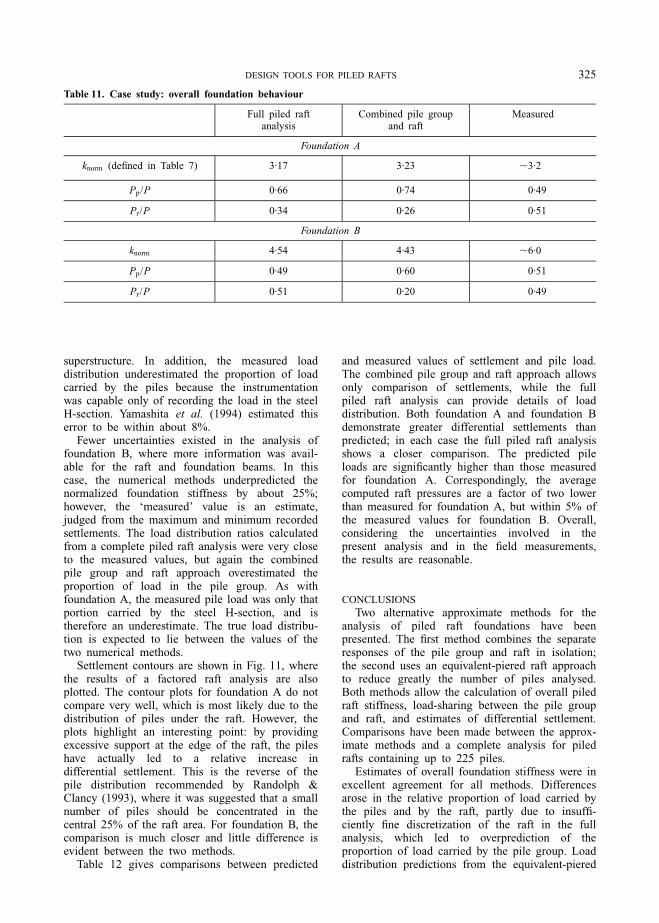
superstructure. In addition, the measured loaddistribution underestimated the proportion of loadcarried by the piles because the instrumentationwas capable only of recording the load in the steelH-section. Yamashita et al. (1994) estimated thiserror to be within about 8%.
Fewer uncertainties existed in the analysis offoundation B, where more information was avail-able for the raft and foundation beams. In thiscase, the numerical methods underpredicted thenormalized foundation stiffness by about 25%;however, the `measured' value is an estimate,judged from the maximum and minimum recordedsettlements. The load distribution ratios calculatedfrom a complete piled raft analysis were very closeto the measured values, but again the combinedpile group and raft approach overestimated theproportion of load in the pile group. As withfoundation A, the measured pile load was only thatportion carried by the steel H-section, and istherefore an underestimate. The true load distribu-tion is expected to lie between the values of thetwo numerical methods.
Settlement contours are shown in Fig. 11, wherethe results of a factored raft analysis are alsoplotted. The contour plots for foundation A do notcompare very well, which is most likely due to thedistribution of piles under the raft. However, theplots highlight an interesting point: by providingexcessive support at the edge of the raft, the pileshave actually led to a relative increase indifferential settlement. This is the reverse of thepile distribution recommended by Randolph &Clancy (1993), where it was suggested that a smallnumber of piles should be concentrated in thecentral 25% of the raft area. For foundation B, thecomparison is much closer and little difference isevident between the two methods.
Table 12 gives comparisons between predicted
and measured values of settlement and pile load.The combined pile group and raft approach allowsonly comparison of settlements, while the fullpiled raft analysis can provide details of loaddistribution. Both foundation A and foundation Bdemonstrate greater differential settlements thanpredicted; in each case the full piled raft analysisshows a closer comparison. The predicted pileloads are signi®cantly higher than those measuredfor foundation A. Correspondingly, the averagecomputed raft pressures are a factor of two lowerthan measured for foundation A, but within 5% ofthe measured values for foundation B. Overall,considering the uncertainties involved in thepresent analysis and in the ®eld measurements,the results are reasonable.
CONCLUSIONS
Two alternative approximate methods for theanalysis of piled raft foundations have beenpresented. The ®rst method combines the separateresponses of the pile group and raft in isolation;the second uses an equivalent-piered raft approachto reduce greatly the number of piles analysed.Both methods allow the calculation of overall piledraft stiffness, load-sharing between the pile groupand raft, and estimates of differential settlement.Comparisons have been made between the approx-imate methods and a complete analysis for piledrafts containing up to 225 piles.
Estimates of overall foundation stiffness were inexcellent agreement for all methods. Differencesarose in the relative proportion of load carried bythe piles and by the raft, partly due to insuf®-ciently ®ne discretization of the raft in the fullanalysis, which led to overprediction of theproportion of load carried by the pile group. Loaddistribution predictions from the equivalent-piered
Table 11. Case study: overall foundation behaviour
Full piled raft Combined pile group Measuredanalysis and raft
Foundation A
knorm (de®ned in Table 7) 3´17 3´23 ,3´2
Pp/P 0´66 0´74 0´49
Pr/P 0´34 0´26 0´51
Foundation B
knorm 4´54 4´43 ,6´0
Pp/P 0´49 0´60 0´51
Pr/P 0´51 0´20 0´49
DESIGN TOOLS FOR PILED RAFTS 325

12
15
12
15
12
12
18
(a)
10 11 10
6
10
9
10
9
13
(c)
15
16
15
13
15
13
13
16
(b)
(d)
13 10
6
13
9
10
10
Fig. 11. Settlement contours (mm): (a, b) foundation A; (c, d) foundation B; (a, c) piled raft analyses; (b, d) raftanalyses factored by kr/kpr
Table 12. Case study: pile loads (MN) and settlement (mm)
Foundation A Foundation B
Pile 1 2 3 6 7 8 11 12 13 16 18 20 2 6 13
Measured 0´62 1´47 1´35 1´32 1´70 0´51 1´26 1´26 1´16 0´15 0´71 0´64 0´53 2´08 1´35load
Predicted 1´81 1´98 2´03 1´93 1´93 1´99 1´74 1´43 1´05 1´14 1´11 1´01 0´87 1´39 1´46load�
Pile 1 3 5 6 8 10 16 18 20 4 7 11 14
Measured 12´5 12´5 15´0 12´5 16´3 17´5 7´5 7´5 7´5 3´0 10´5 8´0 3´0settlement
Predicted 11´9 15´0 11´1 15´1 18´3 14´6 11´3 13´5 10´2 10´5 12´5 8´3 10´4settlement�
Predicted 16´5 16´8 15´0 16´1 16´9 15´4 14´5 13´7 12´7 10´7 13´5 10´6 11´8settlement{
� Full piled raft analysis{ Combined pile group and raft
326 CLANCY AND RANDOLPH

raft approach overestimated the proportion of loadtaken by the pile group, partly through over-prediction of the pile stiffness using an equivalentpier, and partly due to the greater raft areaoccupied by the equivalent pier. Normalizedsettlement pro®les were generally in very goodagreement, with the greatest differences arising forthe combined approach with raft stiffness Krs = 0´1,where differential settlements were overestimatedby up to 5% by the approximate methods.
Two case studies were described, based on piledraft foundations in the Urawa City suburb ofTokyo. The pile group of each foundationcontained only a small number of piles, facilitatinga complete piled raft analysis, but precluding theuse of an equivalent pier approach. Numericalanalysis of the ®rst foundation (foundation A)indicated some limitations in the combined pilegroup and raft approach for predicting differentialsettlements; the method was unable to model theuneven distribution of support provided by thewidely spaced piles. The predictions of overallfoundation behaviour were reasonable, consideringthe uncertainties in foundation geometry. Thesecond foundation (foundation B) had beendocumented in greater detail, allowing a closernumerical representation. In this case, both of thenumerical analyses provided good predictions ofoverall foundation behaviour. Again there was atendency to underestimate differential settlement,but closer predictions were made of pile loaddistribution.
This paper demonstrates that approximations forpiled raft analysis can produce useful results fordesign purposes. The approximate methods aresimple to apply and require low time andcomputational resources. However, where possible,®nal designs should be checked by a full piled raftanalysis.
ACKNOWLEDGEMENTS
The ®rst author gratefully acknowledges ®nan-cial support during the work reported here, throughan Overseas Postgraduate Research Scholarshipfrom the Australian Department of Employment,Education and Training, and a University ResearchScholarship from the University of WesternAustralia.
NOTATIONAg plan area of a pile group
Ap sum of pile cross-sectional areas
dp pile diameter
Epeq equivalent pier modulus
kp overall stiffness of a piled group
kpr overall stiffness of a piled raft
kr overall stiffness of a raft in isolation
Kps pile±soil stiffness ratioLp embedded length of a pilen ratio of circular raft diameter to pile diameter
np total number of piles in a groupPp load carried by a pile groupPr load carried by a raftrm radius of in¯uence of a pile
rpeq equivalent pier radiusR factor used in plotting normalized differential
settlementárp in¯uence of a pile group on the raftís Poisson's ratio of soilr soil inhomogeneity factor
REFERENCESButter®eld, T. & Douglas, R. A. (1981). Flexibility
coef®cients for the design of piles and pile groups.Technical note 108, Construction Industry Researchand Information Association, London.
Chow, Y. K. (1986). Analysis of vertically loaded pilegroups. Int. J. Numer. Anal. Methods Geomech. 10,59±72.
Clancy, P. (1993). Numerical analysis of piled raftfoundations. PhD thesis, University of WesternAustralia.
Clancy, P. & Randolph, M. F. (1993). An approximateanalysis procedure for piled raft foundations. Int. J.Numer. Anal. Methods Geomech. 17, 849±869.
Cooke, R. W. (1986). Piled raft foundations on stiffclaysÐa contribution to design philosophy. GeÂotech-nique 35, No. 2, 169±203.
Davis, E. H. & Poulos, H. G. (1972). The analysis of pileraft systems. Aust. Geomech. J. G2, No. 2, 21±27.
Fleming, W. G. K., Weltman, A. J., Randolph, M. F. &Elson, W. K. (1992). Piling engineering. Glasgow:Blackie.
Giroud, J.-P. (1968). Settlement of a linearly loadedrectangular area. J. Soil Mech. Fdn Engng Div. Am.Soc. Civ. Engrs 94, SM4, 813±831.
Grif®ths, D. V., Clancy, P. & Randolph, M. F. (1991).Piled raft foundation analysis by ®nite elements. Proc.7th Int. Conf. Comput. Methods Adv. Geomech.,Cairns 2, 1153±1157.
Hain, S. J. & Lee, I. K. (1978). The analysis of ¯exibleraft±pile systems. GeÂotechnique 28, No. 1, 65±83.
Mindlin, R. D. (1936). Force at a point in the interior ofa semi-in®nite solid. Physics 7, 195±202.
Ottaviani, M. (1975). Three dimensional ®nite elementanalysis of vertically loaded pile groups. GeÂotech-nique 25, No. 2, 159±174.
Poulos, H. G. (1968). The in¯uence of a rigid pile cap onthe settlement behaviour of an axially-loaded pile.Civ. Engng Trans. Inst. Engrs Aust. CE10, No. 2,206±208.
Poulos, H. G. (1993). Settlement prediction for bored pilegroups. Proc. 2nd Int. Geotech. Semin. Deep FdnsBored Auger Piles, Ghent, 103±117.
Poulos, H. G. & Davis, E. H. (1974). Elastic solutionsfor soil and rock mechanics. Chichester: Wiley.
Poulos, H. G. & Davis, E. H. (1980). Pile foundationanalysis and design, Chichester: Wiley.
Randolph, M. F. (1977). A theoretical study of theperformance of piles. PhD thesis, University ofCambridge.
DESIGN TOOLS FOR PILED RAFTS 327

Randolph, M. F. (1983). Design of Piled Raft Founda-tions. Proceedings of the international symposium onrecent developments in laboratory and ®eld tests andanalysis of geotechnical problems, Bangkok, pp. 525±537.
Randolph, M. F. (1994). Design methods for pile groupsand piled rafts. Proc. 13th Int. Conf. Soil Mech., NewDelhi 5, 1±21.
Randolph, M. F. & Clancy, P. (1993). Ef®cient design ofpiled rafts. Proc. 2nd Int. Geotech. Semin. Deep FdnsBored Auger Piles, Ghent, 119±130.
Randolph, M. F. & Clancy, P. (1994). Design andperformance of a piled raft foundation. Proceedings
of American Society of Civil Engineers GeotechnicalEngineering Division specialty conference, Texas.New York: American Society of Civil Engineers.
Smith, I. M. & Grif®ths, D. V. (1988). Programming the®nite element method, 2nd edn. Chichester: Wiley.
Yamashita, K. & Kakurai, M. (1991). Settlementbehaviour of the raft foundation with friction piles.Proc. 4th Int. Conf. Piling Deep Fdns, Stressa,461±466.
Yamashita, K., Kakurai, M. & Yamada, T. (1994).Investigation of a piled raft foundation on stiff clay.Proc. 13th Int. Conf. Soil Mech., New Delhi 2, 543±546.
328 CLANCY AND RANDOLPH