simotion basic control basic control function manual 08/2008 edition safety guidelines safety...
TRANSCRIPT
SIMOTION Basic Control
________________________________________________________
Preface
Description 1
Function blocks 2
Application example 3
Appendix A
SIMOTION
Basic Control
Function Manual
08/2008 Edition
Safety Guidelines Safety Guidelines This manual contains notices you have to observe in order to ensure your personal safety, as well as to prevent damage to property. The notices referring to your personal safety are highlighted in the manual by a safety alert symbol, notices referring only to property damage have no safety alert symbol. These notices shown below are graded according to the degree of danger.
DANGER indicates that death or severe personal injury will result if proper precautions are not taken.
WARNING indicates that death or severe personal injury may result if proper precautions are not taken.
CAUTION with a safety alert symbol, indicates that minor personal injury can result if proper precautions are not taken.
CAUTION without a safety alert symbol, indicates that property damage can result if proper precautions are not taken.
NOTICE indicates that an unintended result or situation can occur if the corresponding information is not taken into account.
If more than one degree of danger is present, the warning notice representing the highest degree of danger will be used. A notice warning of injury to persons with a safety alert symbol may also include a warning relating to property damage.
Qualified Personnel The device/system may only be set up and used in conjunction with this documentation. Commissioning and operation of a device/system may only be performed by qualified personnel. Within the context of the safety notes in this documentation qualified persons are defined as persons who are authorized to commission, ground and label devices, systems and circuits in accordance with established safety practices and standards.
Prescribed Usage Note the following:
WARNING This device may only be used for the applications described in the catalog or the technical description and only in connection with devices or components from other manufacturers which have been approved or recommended by Siemens. Correct, reliable operation of the product requires proper transport, storage, positioning and assembly as well as careful operation and maintenance.
Trademarks All names identified by ® are registered trademarks of the Siemens AG. The remaining trademarks in this publication may be trademarks whose use by third parties for their own purposes could violate the rights of the owner.
Disclaimer of Liability We have reviewed the contents of this publication to ensure consistency with the hardware and software described. Since variance cannot be precluded entirely, we cannot guarantee full consistency. However, the information in this publication is reviewed regularly and any necessary corrections are included in subsequent editions.
Siemens AG Industry Sector Postfach 48 48 90327 NÜRNBERG GERMANY
Ⓟ 08/2008
Copyright © Siemens AG 2008. Technical data subject to change
Basic Control Function Manual, 08/2008 Edition 3
Preface
Contents of the function manual This document is part of the SIMOTION Programming References documentation package. This manual will assist you in working with the function blocks of the "Basic Control" software package. You will learn how the function blocks work.
Function block The function blocks for "Basic Control" are part of the program library of the "SIMOTION SCOUT" engineering system.
SIMOTION Documentation An overview of the SIMOTION documentation can be found in a separate list of references. This documentation is included as electronic documentation with the supplied SIMOTION SCOUT. The SIMOTION documentation consists of 9 documentation packages containing approximately 80 SIMOTION documents and documents on related systems (e.g. SINAMICS). The following documentation packages are available for SIMOTION V4.1 SP2: ● SIMOTION Engineering System ● SIMOTION System and Function Descriptions ● SIMOTION Diagnostics ● SIMOTION Programming ● SIMOTION Programming - References ● SIMOTION C ● SIMOTION P350 ● SIMOTION D4xx ● SIMOTION Supplementary Documentation
Preface
Basic Control 4 Function Manual, 08/2008 Edition
Hotline and Internet addresses
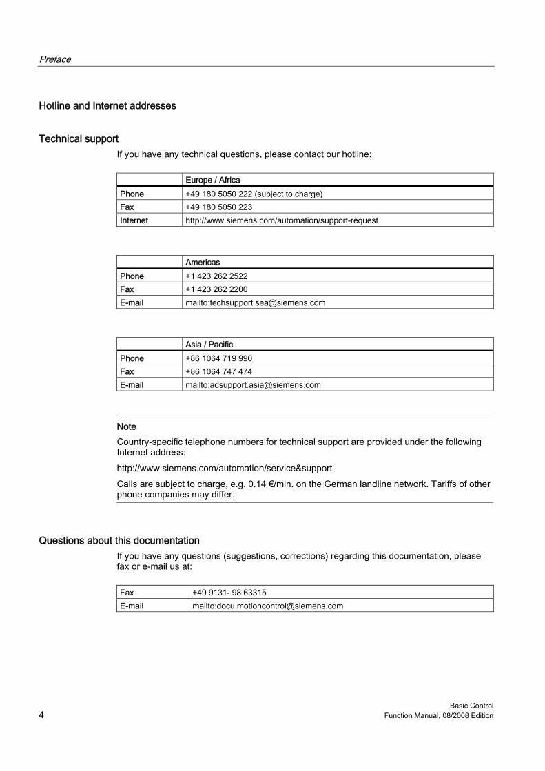
Technical support If you have any technical questions, please contact our hotline:
Europe / Africa Phone +49 180 5050 222 (subject to charge) Fax +49 180 5050 223 Internet http://www.siemens.com/automation/support-request
Americas Phone +1 423 262 2522 Fax +1 423 262 2200 E-mail mailto:[email protected]
Asia / Pacific Phone +86 1064 719 990 Fax +86 1064 747 474 E-mail mailto:[email protected]
Note Country-specific telephone numbers for technical support are provided under the following Internet address: http://www.siemens.com/automation/service&support Calls are subject to charge, e.g. 0.14 €/min. on the German landline network. Tariffs of other phone companies may differ.
Questions about this documentation If you have any questions (suggestions, corrections) regarding this documentation, please fax or e-mail us at:
Fax +49 9131- 98 63315 E-mail mailto:[email protected]
Preface
Basic Control Function Manual, 08/2008 Edition 5
Siemens Internet address The latest information about SIMOTION products, product support, and FAQs can be found on the Internet at: ● General information:
– http://www.siemens.de/simotion (German) – http://www.siemens.com/simotion (international)
● Product support: – http://support.automation.siemens.com/WW/view/en/10805436
Additional support We also offer introductory courses to help you familiarize yourself with SIMOTION. Please contact your regional training center or our main training center at D-90027 Nuremberg, phone +49 (911) 895 3202. Information about training courses on offer can be found at: www.sitrain.com

Basic Control Function Manual, 08/2008 Edition 7
Table of contents Preface ...................................................................................................................................................... 3 1 Description................................................................................................................................................. 9
1.1 General ..........................................................................................................................................9 1.2 Product description ......................................................................................................................10
2 Function blocks........................................................................................................................................ 11 2.1 Overview ......................................................................................................................................11 2.2 Integrating the function blocks in the user project .......................................................................12 2.3 Continuous control with the _CTRL_pid function block ...............................................................13 2.4 Step control using the _CTRL_piStep function block...................................................................20 2.5 Pulse width modulation (PWM) with the _CTRL_pwm function block .........................................26 2.6 Calling function blocks .................................................................................................................35
3 Application example................................................................................................................................. 37 3.1 Application example.....................................................................................................................37 3.2 Variables used and preassignments............................................................................................41
A Appendix.................................................................................................................................................. 43 A.1 List of parameters ........................................................................................................................43 A.2 List of abbreviations .....................................................................................................................46
Index........................................................................................................................................................ 47

Basic Control Function Manual, 08/2008 Edition 9
Description 11.1 1.1 General
The "Basic Control" software consists of the function blocks (FBs) for a continuous PID control (_CTRL_pid) and for a step control (_CTRL_piStep) plus the function block for pulse width modulation (_CTRL_pwm). The function blocks are software controllers, with each block containing the entire controller functionality. FBs can be called more than once. The _CTRL_pwm function block is used in connection with the _CTRL_pid function block in order to obtain a controller with pulse output for proportional actuators.
Description 1.2 Product description
Basic Control 10 Function Manual, 08/2008 Edition
1.2 1.2 Product description
Basic Functions A controller created using function blocks comprises a series of subfunctions that can be parameterized by you. Apart from the control algorithm for a continuous-action or step controller, functions for setpoint and actual value preparation and correction of the manipulated variable are also integrated in the blocks.
Possible applications A closed-loop control system created using the "Basic Control" function blocks is basically neutral in terms of its application. Its controlling power and thus processing speed depends entirely on the performance of the SIMOTION hardware used. It is capable of controlling slow systems (temperatures, fill levels, etc.) as well as very fast systems (flows, speeds, etc.).
Controlled system analysis
Note The static behavior (gain) and the dynamic properties (delay, dead time, integration constant, etc.) of the controlled system are critical factors in the layout and design of the controller and the settings for its static parameters (proportional component) and dynamic parameters (integral and derivative component). It is therefore essential for you to know the controlled system type and its characteristic data.
Controller selection
Note The properties of controlled systems are determined by specific process/machine features. It is unlikely that they can be modified in any way. For this reason, you can obtain good control quality only by selecting the most suitable controller type for the controlled system in question and by adapting it correctly to the dynamic response of the system.
Requirement The following software versions are required for the standard functions described in this documentation: ● SIMOTION SCOUT V4.0 or higher ● SIMOTION Kernel V4.0 or higher ● SIMOTION Technology Packages V4.0 or higher
Basic Control Function Manual, 08/2008 Edition 11
Function blocks 22.1 2.1 Overview
This chapter describes the function blocks for "Basic Control". You will find a general description of the data structure containing all input and output parameters of the relevant function block as well as a description of the function block call. Examples will be used to show you how to do the following: ● Integrate the function block ● Instantiate the function block ● Set up variables for the data structure ● Call an instance you have created ● Assign values to input parameters ● Access output parameters of the function block
Function blocks 2.2 Integrating the function blocks in the user project
Basic Control 12 Function Manual, 08/2008 Edition
2.2 2.2 Integrating the function blocks in the user project
Creating the FBs instance in the user project The function blocks are part of the program library of the SIMOTION SCOUT engineering system. For working with the function blocks, an instance has to be created in the user project for each function block used. Example:
VAR_GLOBAL ... myFBPID:_CTRL_pid; // create "_CTRL_pid" instance myFBPISTEP:_CTRL_piStep; // create "_CTRL_piStep" instance myFBPWM:_CTRL_pwm; // create "_CTRL_pwm" instance ... END_VAR
Call (LAD representation) The LAD representation of the individual function blocks can be found in the respective function block descriptions.
Application example The application example is included on the "Utilities & Applications" CD-ROM and is available for various SIMOTION hardware platforms. The "Utilities & Applications" CD-ROM is provided free of charge with SIMOTION SCOUT.
Function blocks 2.3 Continuous control with the _CTRL_pid function block
Basic Control Function Manual, 08/2008 Edition 13
2.3 2.3 Continuous control with the _CTRL_pid function block
Introduction The _CTRL_pid function block is used to control technical processes with continuous input and output variables on SIMOTION systems. Using parameterization, you can activate or deactivate subfunctions of the PID controller and thus adapt it to the controlled system in question.
Application You can use the controller individually as a fixed-setpoint PID controller or in multi-loop feedback controls as a cascade, combined, or ratio controller. Its operating principle is based on the PID control algorithm of the sampling controller with analog output signal, possibly supplemented by a pulse shaper stage for generating pulse-width-modulated output signals for two- or three-step controls with proportional actuators.
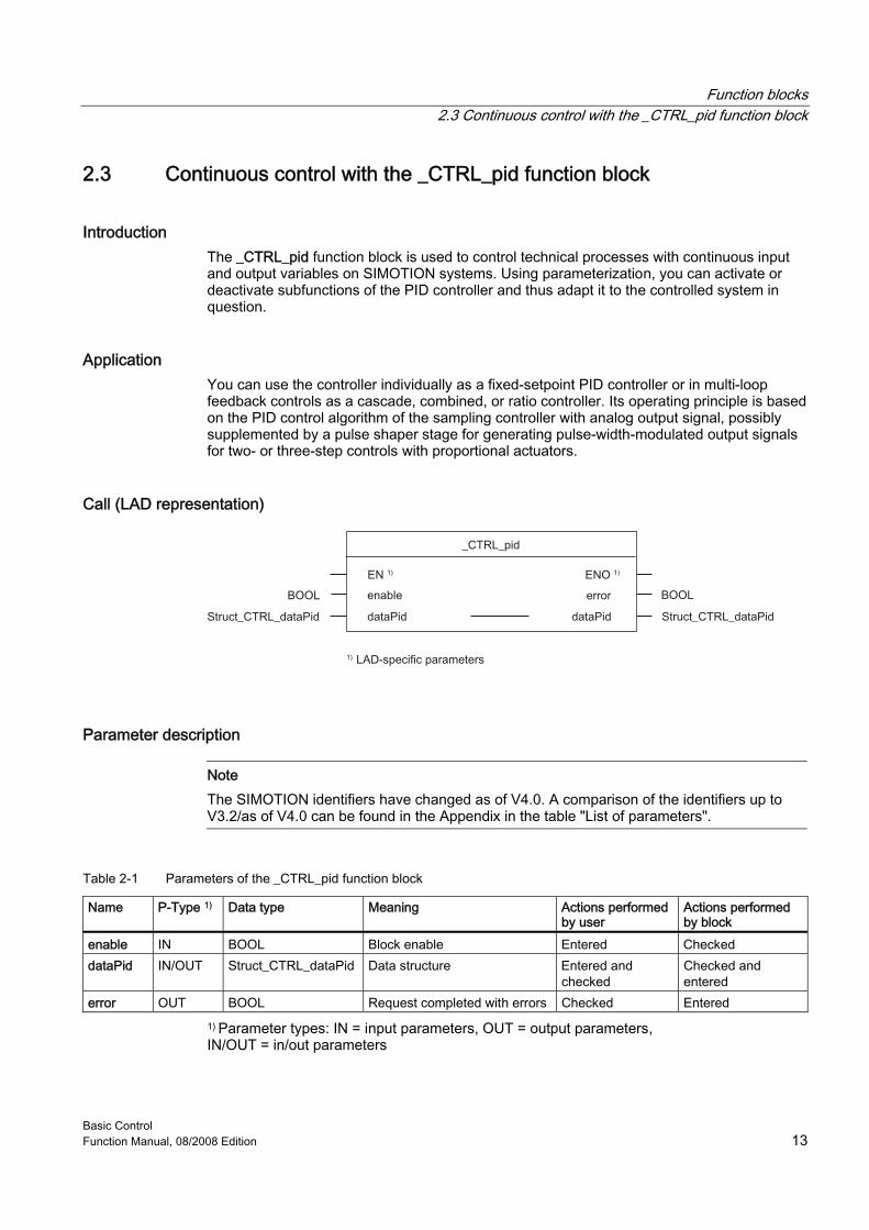
Call (LAD representation)
Parameter description
Note The SIMOTION identifiers have changed as of V4.0. A comparison of the identifiers up to V3.2/as of V4.0 can be found in the Appendix in the table "List of parameters".
Table 2-1 Parameters of the _CTRL_pid function block
Name P-Type 1) Data type Meaning Actions performed by user
Actions performed by block
enable IN BOOL Block enable Entered Checked dataPid IN/OUT Struct_CTRL_dataPid Data structure Entered and
checked Checked and entered
error OUT BOOL Request completed with errors Checked Entered 1) Parameter types: IN = input parameters, OUT = output parameters, IN/OUT = in/out parameters
Function blocks 2.3 Continuous control with the _CTRL_pid function block
Basic Control 14 Function Manual, 08/2008 Edition
Data structure of the _CTRL_pid function block The data structure of type Struct_CTRL_dataPid contains all input and output parameters of the _CTRL_pid function block. The data structure is used by the _CTRL_pid function block. Elements in the data structure are accessed using a variable of data type Struct_CTRL_dataPid, which you must define yourself. The Struct_CTRL_dataPid data structure is shown in the table below.
Note The SIMOTION identifiers have changed as of V4.0. A comparison of the identifiers up to V3.2/as of V4.0 can be found in the Appendix in the table "List of parameters".
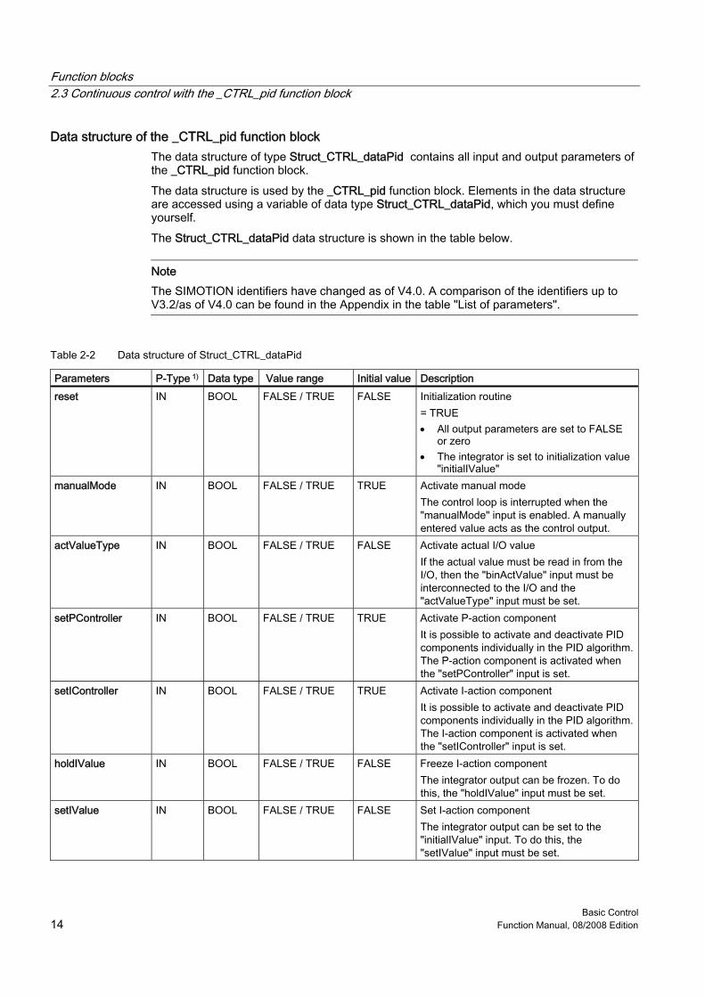
Table 2-2 Data structure of Struct_CTRL_dataPid
Parameters P-Type 1) Data type Value range Initial value Description reset IN BOOL FALSE / TRUE FALSE Initialization routine
= TRUE • All output parameters are set to FALSE
or zero • The integrator is set to initialization value
"initialIValue" manualMode IN BOOL FALSE / TRUE TRUE Activate manual mode
The control loop is interrupted when the "manualMode" input is enabled. A manually entered value acts as the control output.
actValueType IN BOOL FALSE / TRUE FALSE Activate actual I/O value If the actual value must be read in from the I/O, then the "binActValue" input must be interconnected to the I/O and the "actValueType" input must be set.
setPController IN BOOL FALSE / TRUE TRUE Activate P-action component It is possible to activate and deactivate PID components individually in the PID algorithm. The P-action component is activated when the "setPController" input is set.
setIController IN BOOL FALSE / TRUE TRUE Activate I-action component It is possible to activate and deactivate PID components individually in the PID algorithm. The I-action component is activated when the "setIController" input is set.
holdIValue IN BOOL FALSE / TRUE FALSE Freeze I-action component The integrator output can be frozen. To do this, the "holdIValue" input must be set.
setIValue IN BOOL FALSE / TRUE FALSE Set I-action component The integrator output can be set to the "initialIValue" input. To do this, the "setIValue" input must be set.
Function blocks 2.3 Continuous control with the _CTRL_pid function block
Basic Control Function Manual, 08/2008 Edition 15
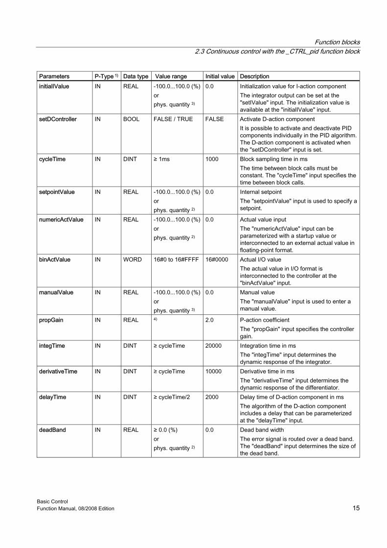
Parameters P-Type 1) Data type Value range Initial value Description initialIValue IN REAL -100.0...100.0 (%)
or phys. quantity 3)
0.0 Initialization value for I-action component The integrator output can be set at the "setIValue" input. The initialization value is available at the "initialIValue" input.
setDController IN BOOL FALSE / TRUE FALSE Activate D-action component It is possible to activate and deactivate PID components individually in the PID algorithm. The D-action component is activated when the "setDController" input is set.
cycleTime IN DINT ≥ 1ms 1000 Block sampling time in ms The time between block calls must be constant. The "cycleTime" input specifies the time between block calls.
setpointValue IN REAL -100.0...100.0 (%)or phys. quantity 2)
0.0 Internal setpoint The "setpointValue" input is used to specify a setpoint.
numericActValue IN REAL -100.0...100.0 (%)or phys. quantity 2)
0.0 Actual value input The "numericActValue" input can be parameterized with a startup value or interconnected to an external actual value in floating-point format.
binActValue IN WORD 16#0 to 16#FFFF 16#0000 Actual I/O value The actual value in I/O format is interconnected to the controller at the "binActValue" input.
manualValue IN REAL -100.0...100.0 (%)or phys. quantity 3)
0.0 Manual value The "manualValue" input is used to enter a manual value.
propGain IN REAL 4) 2.0 P-action coefficient The "propGain" input specifies the controller gain.
integTime IN DINT ≥ cycleTime 20000 Integration time in ms The "integTime" input determines the dynamic response of the integrator.
derivativeTime IN DINT ≥ cycleTime 10000 Derivative time in ms The "derivativeTime" input determines the dynamic response of the differentiator.
delayTime IN DINT ≥ cycleTime/2 2000 Delay time of D-action component in ms The algorithm of the D-action component includes a delay that can be parameterized at the "delayTime" input.
deadBand IN REAL ≥ 0.0 (%) or phys. quantity 2)
0.0 Dead band width The error signal is routed over a dead band. The "deadBand" input determines the size of the dead band.
Function blocks 2.3 Continuous control with the _CTRL_pid function block
Basic Control 16 Function Manual, 08/2008 Edition
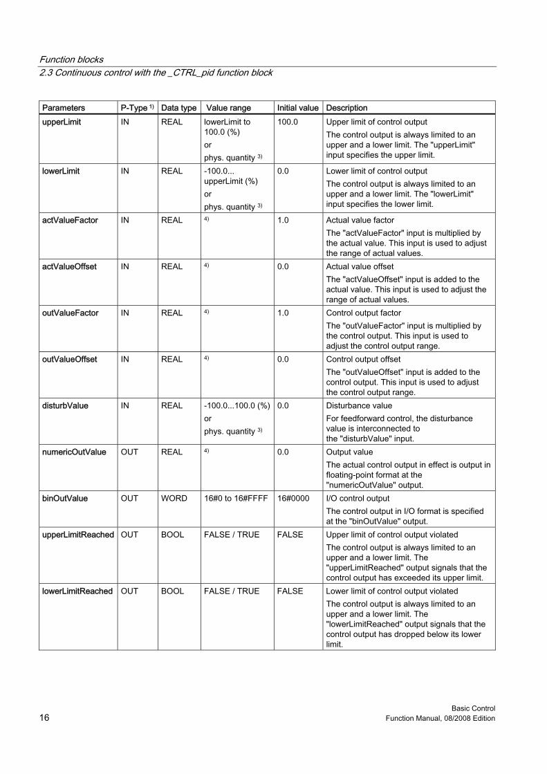
Parameters P-Type 1) Data type Value range Initial value Description upperLimit IN REAL lowerLimit to
100.0 (%) or phys. quantity 3)
100.0 Upper limit of control output The control output is always limited to an upper and a lower limit. The "upperLimit" input specifies the upper limit.
lowerLimit IN REAL -100.0... upperLimit (%) or phys. quantity 3)
0.0 Lower limit of control output The control output is always limited to an upper and a lower limit. The "lowerLimit" input specifies the lower limit.
actValueFactor IN REAL 4) 1.0 Actual value factor The "actValueFactor" input is multiplied by the actual value. This input is used to adjust the range of actual values.
actValueOffset IN REAL 4) 0.0 Actual value offset The "actValueOffset" input is added to the actual value. This input is used to adjust the range of actual values.
outValueFactor IN REAL 4) 1.0 Control output factor The "outValueFactor" input is multiplied by the control output. This input is used to adjust the control output range.
outValueOffset IN REAL 4) 0.0 Control output offset The "outValueOffset" input is added to the control output. This input is used to adjust the control output range.
disturbValue IN REAL -100.0...100.0 (%)or phys. quantity 3)
0.0 Disturbance value For feedforward control, the disturbance value is interconnected to the "disturbValue" input.
numericOutValue OUT REAL 4) 0.0 Output value The actual control output in effect is output in floating-point format at the "numericOutValue" output.
binOutValue OUT WORD 16#0 to 16#FFFF 16#0000 I/O control output The control output in I/O format is specified at the "binOutValue" output.
upperLimitReached OUT BOOL FALSE / TRUE FALSE Upper limit of control output violated The control output is always limited to an upper and a lower limit. The "upperLimitReached" output signals that the control output has exceeded its upper limit.
lowerLimitReached OUT BOOL FALSE / TRUE FALSE Lower limit of control output violated The control output is always limited to an upper and a lower limit. The "lowerLimitReached" output signals that the control output has dropped below its lower limit.
Function blocks 2.3 Continuous control with the _CTRL_pid function block
Basic Control Function Manual, 08/2008 Edition 17
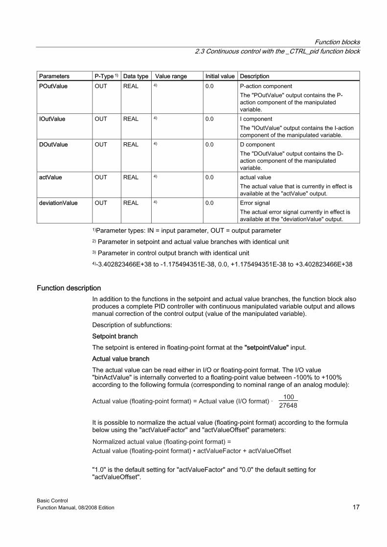
Parameters P-Type 1) Data type Value range Initial value Description POutValue OUT REAL 4) 0.0 P-action component
The "POutValue" output contains the P-action component of the manipulated variable.
IOutValue OUT REAL 4) 0.0 I component The "IOutValue" output contains the I-action component of the manipulated variable.
DOutValue OUT REAL 4) 0.0 D component The "DOutValue" output contains the D-action component of the manipulated variable.
actValue OUT REAL 4) 0.0 actual value The actual value that is currently in effect is available at the "actValue" output.
deviationValue OUT REAL 4) 0.0 Error signal The actual error signal currently in effect is available at the "deviationValue" output.
1)Parameter types: IN = input parameter, OUT = output parameter 2) Parameter in setpoint and actual value branches with identical unit 3) Parameter in control output branch with identical unit 4)-3.402823466E+38 to -1.175494351E-38, 0.0, +1.175494351E-38 to +3.402823466E+38
Function description In addition to the functions in the setpoint and actual value branches, the function block also produces a complete PID controller with continuous manipulated variable output and allows manual correction of the control output (value of the manipulated variable). Description of subfunctions: Setpoint branch The setpoint is entered in floating-point format at the "setpointValue" input. Actual value branch The actual value can be read either in I/O or floating-point format. The I/O value "binActValue" is internally converted to a floating-point value between -100% to +100% according to the following formula (corresponding to nominal range of an analog module):
It is possible to normalize the actual value (floating-point format) according to the formula below using the "actValueFactor" and "actValueOffset" parameters:
"1.0" is the default setting for "actValueFactor" and "0.0" the default setting for "actValueOffset".
Function blocks 2.3 Continuous control with the _CTRL_pid function block
Basic Control 18 Function Manual, 08/2008 Edition
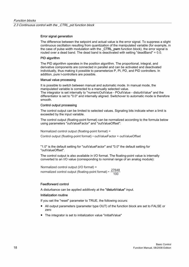
Error signal generation The difference between the setpoint and actual value is the error signal. To suppress a slight continuous oscillation resulting from quantization of the manipulated variable (for example, in the case of pulse width modulation with the _CTRL_pwm function block), the error signal is routed over a dead band. The dead band is deactivated with setting "deadBand" = 0.0. PID algorithm The PID algorithm operates in the position algorithm. The proportional, integral, and derivative components are connected in parallel and can be activated and deactivated individually, thus making it possible to parameterize P, PI, PD, and PID controllers. In addition, pure I-controllers are possible. Manual value processing It is possible to switch between manual and automatic mode. In manual mode, the manipulated variable is corrected to a manually selected value. The integrator is set internally to "numericOutValue - POutValue - disturbValue" and the differentiator is set to "0.0" and internally aligned. Switchover to automatic mode is therefore smooth. Control output processing The control output can be limited to selected values. Signaling bits indicate when a limit is exceeded by the input variable. The control output (floating-point format) can be normalized according to the formula below using parameters "outValueFactor" and "outValueOffset":
"1.0" is the default setting for "outValueFactor" and "0.0" the default setting for "outValueOffset". The control output is also available in I/O format. The floating-point value is internally converted to an I/O value (corresponding to nominal range of an analog module):
Feedforward control A disturbance can be applied additively at the "disturbValue" input. Initialization routine If you set the "reset" parameter to TRUE, the following occurs: ● All output parameters (parameter type OUT) of the function block are set to FALSE or
zero ● The integrator is set to initialization value "initialIValue"
Function blocks 2.3 Continuous control with the _CTRL_pid function block
Basic Control Function Manual, 08/2008 Edition 19
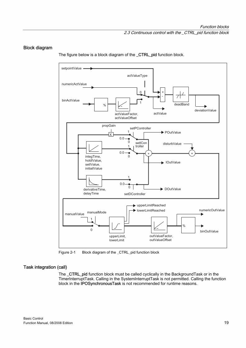
Block diagram The figure below is a block diagram of the _CTRL_pid function block.
Figure 2-1 Block diagram of the _CTRL_pid function block
Task integration (call) The _CTRL_pid function block must be called cyclically in the BackgroundTask or in the TimerInterruptTask. Calling in the SystemInterruptTask is not permitted. Calling the function block in the IPOSynchronousTask is not recommended for runtime reasons.
Function blocks 2.4 Step control using the _CTRL_piStep function block
Basic Control 20 Function Manual, 08/2008 Edition
2.4 2.4 Step control using the _CTRL_piStep function block
Introduction The _CTRL_piStep function block is used to control technical processes with binary control output signals for integrating actuators on SIMOTION systems. Using parameterization, you can activate or deactivate subfunctions of the PI step controller and thus adapt it to the controlled system in question.
Application You can use the controller individually as a fixed-setpoint PI controller or in secondary control loops as cascade, combined, or ratio controllers, but not as a master controller. Its operating principle is based on the PI control algorithm of the sampling controller, supplemented by function elements for generating a binary output signal from an analog actuating signal.
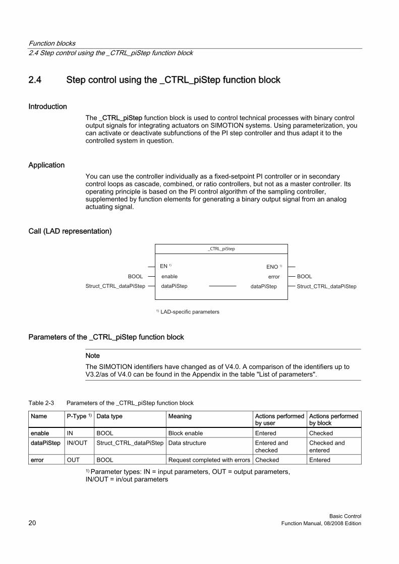
Call (LAD representation)
_CTRL_piStep
1) 1)
Parameters of the _CTRL_piStep function block
Note The SIMOTION identifiers have changed as of V4.0. A comparison of the identifiers up to V3.2/as of V4.0 can be found in the Appendix in the table "List of parameters".
Table 2-3 Parameters of the _CTRL_piStep function block
Name P-Type 1) Data type Meaning Actions performed by user
Actions performed by block
enable IN BOOL Block enable Entered Checked dataPiStep IN/OUT Struct_CTRL_dataPiStep Data structure Entered and
checked Checked and entered
error OUT BOOL Request completed with errors Checked Entered 1) Parameter types: IN = input parameters, OUT = output parameters, IN/OUT = in/out parameters

Function blocks 2.4 Step control using the _CTRL_piStep function block
Basic Control Function Manual, 08/2008 Edition 21
Data structure of the _CTRL_piStep function block The data structure of type Struct_CTRL_dataPiStep contains all input and output parameters of the _CTRL_piStep function block. The data structure is used by the _CTRL_piStep function block. Elements in the data structure are accessed using a variable of data type Struct_CTRL_dataPiStep, which you must define yourself. The Struct_CTRL_dataPiStep data structure is shown in the table below.
Note The SIMOTION identifiers have changed as of V4.0. A comparison of the identifiers up to V3.2/as of V4.0 can be found in the Appendix in the table "List of parameters".
Table 2-4 Data structure of Struct_CTRL_dataPiStep
Parameters P-Type 1) Data type Value range Initial value Description reset IN BOOL FALSE / TRUE FALSE Initialization routine
= TRUE All output parameters are set to FALSE or zero
actValueType IN BOOL FALSE / TRUE FALSE Activate actual I/O value If the actual value must be read in from the I/O, then the "binActValue" input must be interconnected to the I/O and the "actValueType" input must be set.
cycleTime IN DINT ≥1 ms 1000 Sampling time in ms The time between block calls must be constant. The "cycleTime" input specifies the time between block calls.
setpointValue IN REAL -100.0...100.0 (%)or phys. quantity 2)
0.0 Internal setpoint The "setpointValue" input is used to specify a setpoint.
numericActValue IN REAL -100.0...100.0 (%)or phys. quantity 2)
0.0 Actual value input The "numericActValue" input can be parameterized with a startup value or interconnected to an external actual value in floating-point format.
binActValue IN WORD 16#0 to 16#FFFF 16#0000 Actual I/O value The actual value in I/O format is interconnected to the controller at the "binActValue" input.
propGain IN REAL 4) 2.0 P-action coefficient The "propGain" input specifies the controller gain.
integTime IN DINT ≥ cycleTime 20000 Integration time in ms The "integTime" input determines the dynamic response of the integrator.
Function blocks 2.4 Step control using the _CTRL_piStep function block
Basic Control 22 Function Manual, 08/2008 Edition
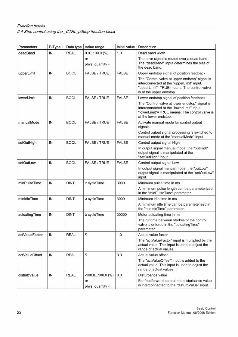
Parameters P-Type 1) Data type Value range Initial value Description deadBand IN REAL 0.0...100.0 (%)
or phys. quantity 2)
1.0 Dead band width The error signal is routed over a dead band. The "deadBand" input determines the size of the dead band.
upperLimit IN BOOL FALSE / TRUE FALSE Upper endstop signal of position feedback The "Control valve at upper endstop" signal is interconnected at the "upperLimit" input. "upperLimit"=TRUE means: The control valve is at the upper endstop.
lowerLimit IN BOOL FALSE / TRUE FALSE Lower endstop signal of position feedback The "Control valve at lower endstop" signal is interconnected at the "lowerLimit" input. "lowerLimit"=TRUE means: The control valve is at the lower endstop.
manualMode IN BOOL FALSE / TRUE FALSE Activate manual mode for control output signals Control output signal processing is switched to manual mode at the "manualMode" input.
setOutHigh IN BOOL FALSE / TRUE FALSE Control output signal High In output signal manual mode, the "outHigh" output signal is manipulated at the "setOutHigh" input.
setOutLow IN BOOL FALSE / TRUE FALSE Control output signal Low In output signal manual mode, the "outLow" output signal is manipulated at the "setOutLow" input.
minPulseTime IN DINT ≥ cycleTime 3000 Minimum pulse time in ms A minimum pulse length can be parameterized in the "minPulseTime" parameter.
minIdleTime IN DINT ≥ cycleTime 3000 Minimum idle time in ms A minimum idle time can be parameterized in the "minIdleTime" parameter.
actuatingTime IN DINT ≥ cycleTime 30000 Motor actuating time in ms The runtime between strokes of the control valve is entered in the "actuatingTime" parameter.
actValueFactor IN REAL 4) 1.0 Actual value factor The "actValueFactor" input is multiplied by the actual value. This input is used to adjust the range of actual values.
actValueOffset IN REAL 4) 0.0 Actual value offset The "actValueOffset" input is added to the actual value. This input is used to adjust the range of actual values.
disturbValue IN REAL -100.0...100.0 (%)or phys. quantity 3)
0.0 Disturbance value For feedforward control, the disturbance value is interconnected to the "disturbValue" input.
Function blocks 2.4 Step control using the _CTRL_piStep function block
Basic Control Function Manual, 08/2008 Edition 23
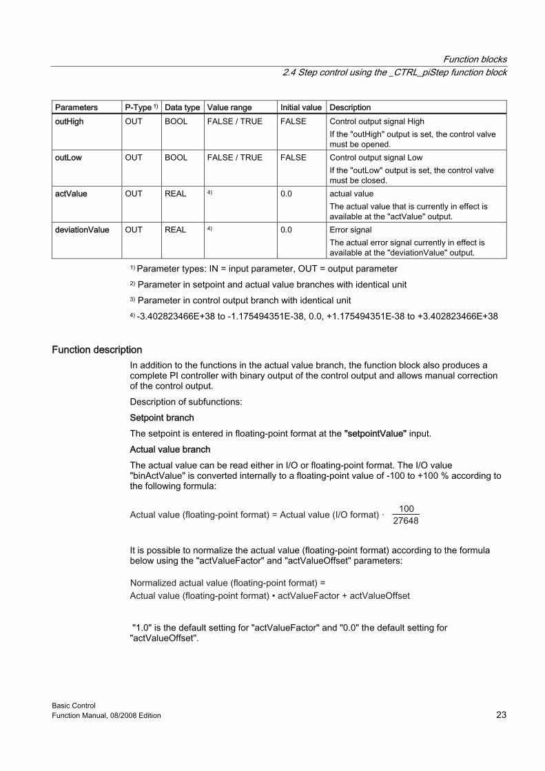
Parameters P-Type 1) Data type Value range Initial value Description outHigh OUT BOOL FALSE / TRUE FALSE Control output signal High
If the "outHigh" output is set, the control valve must be opened.
outLow OUT BOOL FALSE / TRUE FALSE Control output signal Low If the "outLow" output is set, the control valve must be closed.
actValue OUT REAL 4) 0.0 actual value The actual value that is currently in effect is available at the "actValue" output.
deviationValue OUT REAL 4) 0.0 Error signal The actual error signal currently in effect is available at the "deviationValue" output.
1) Parameter types: IN = input parameter, OUT = output parameter 2) Parameter in setpoint and actual value branches with identical unit 3) Parameter in control output branch with identical unit 4) -3.402823466E+38 to -1.175494351E-38, 0.0, +1.175494351E-38 to +3.402823466E+38
Function description In addition to the functions in the actual value branch, the function block also produces a complete PI controller with binary output of the control output and allows manual correction of the control output. Description of subfunctions: Setpoint branch The setpoint is entered in floating-point format at the "setpointValue" input. Actual value branch The actual value can be read either in I/O or floating-point format. The I/O value "binActValue" is converted internally to a floating-point value of -100 to +100 % according to the following formula:
It is possible to normalize the actual value (floating-point format) according to the formula below using the "actValueFactor" and "actValueOffset" parameters:
"1.0" is the default setting for "actValueFactor" and "0.0" the default setting for "actValueOffset".
Function blocks 2.4 Step control using the _CTRL_piStep function block
Basic Control 24 Function Manual, 08/2008 Edition
Error signal generation The difference between the setpoint and actual value is the error signal. To suppress a slight continuous oscillation resulting from quantization of the manipulated variable (limited resolution of control output by the control valve), the error signal is routed over a dead band. The dead band is deactivated with setting "deadBand" = 0.0. PI step algorithm The PI step controller operates without actuating signal feedback at the output. A signal is generated to indicate that the upper or lower limit has been reached. The I-action component of the PI algorithm and the "upper/lower limit reached" signal are calculated in an integrator and compared as a feedback value with the remaining P-action component. The difference is applied to a three-step element and a pulse shaper that generates the pulses for the control valve. The operating frequency of the controller is reduced through adaptation of the response threshold of the three-step element. Feedforward control A disturbance can be applied additively at the "disturbValue" input. Initialization routine If you set the "reset" parameter to TRUE, all output parameters (parameter type OUT) of the function block are set to FALSE or zero.

Function blocks 2.4 Step control using the _CTRL_piStep function block
Basic Control Function Manual, 08/2008 Edition 25
Block diagram The figure below is a block diagram of the _CTRL_piStep function block.
Figure 2-2 Block diagram of the _CTRL_piStep function block
Task integration (call) The _CTRL_piStep function block must be called cyclically in the BackgroundTask or in the TimerInterruptTask. Calling in the SystemInterruptTask is not permitted. Calling the function block in the IPOSynchronousTask is not recommended for runtime reasons.
Function blocks 2.5 Pulse width modulation (PWM) with the _CTRL_pwm function block
Basic Control 26 Function Manual, 08/2008 Edition
2.5 2.5 Pulse width modulation (PWM) with the _CTRL_pwm function block
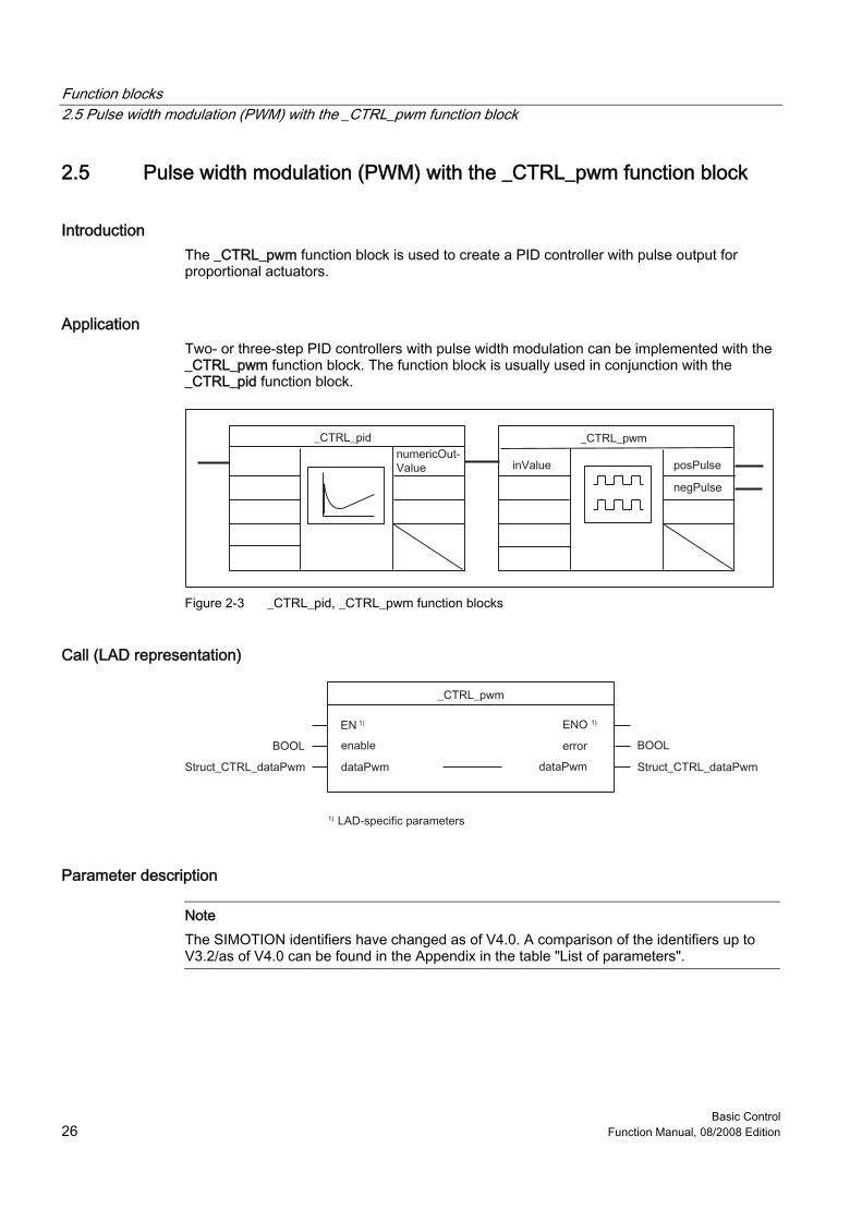
Introduction The _CTRL_pwm function block is used to create a PID controller with pulse output for proportional actuators.
Application Two- or three-step PID controllers with pulse width modulation can be implemented with the _CTRL_pwm function block. The function block is usually used in conjunction with the _CTRL_pid function block.
Figure 2-3 _CTRL_pid, _CTRL_pwm function blocks
Call (LAD representation)
Parameter description
Note The SIMOTION identifiers have changed as of V4.0. A comparison of the identifiers up to V3.2/as of V4.0 can be found in the Appendix in the table "List of parameters".
Function blocks 2.5 Pulse width modulation (PWM) with the _CTRL_pwm function block
Basic Control Function Manual, 08/2008 Edition 27
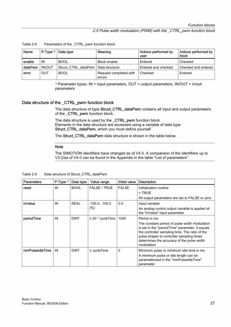
Table 2-5 Parameters of the _CTRL_pwm function block
Name P-Type 1) Data type Meaning Actions performed by user
Actions performed by block
enable IN BOOL Block enable Entered Checked dataPwm IN/OUT Struct_CTRL_dataPwm Data structure Entered and checked Checked and entered error OUT BOOL Request completed with
errors Checked Entered
1) Parameter types: IN = input parameters, OUT = output parameters, IN/OUT = in/out parameters
Data structure of the _CTRL_pwm function block The data structure of type Struct_CTRL_dataPwm contains all input and output parameters of the _CTRL_pwm function block. The data structure is used by the _CTRL_pwm function block. Elements in the data structure are accessed using a variable of data type Struct_CTRL_dataPwm, which you must define yourself. The Struct_CTRL_dataPwm data structure is shown in the table below.
Note The SIMOTION identifiers have changed as of V4.0. A comparison of the identifiers up to V3.2/as of V4.0 can be found in the Appendix in the table "List of parameters".
Table 2-6 Data structure of Struct_CTRL_dataPwm
Parameters P-Type 1) Data type Value range Initial value Description reset IN BOOL FALSE / TRUE FALSE Initialization routine
= TRUE All output parameters are set to FALSE or zero
inValue IN REAL -100.0...100.0 (%)
0.0 Input variable An analog control output variable is applied at the "inValue" input parameter.
periodTime IN DINT ≥ 20 * cycleTime 1000 Period in ms The constant period of pulse width modulation is set in the "periodTime" parameter. It equals the controller sampling time. The ratio of the pulse shaper to controller sampling times determines the accuracy of the pulse width modulation.
minPulseIdleTime IN DINT ≥ cycleTime 0 Minimum pulse or minimum idle time in ms A minimum pulse or idle length can be parameterized in the "minPulseIdleTime" parameter.
Function blocks 2.5 Pulse width modulation (PWM) with the _CTRL_pwm function block
Basic Control 28 Function Manual, 08/2008 Edition
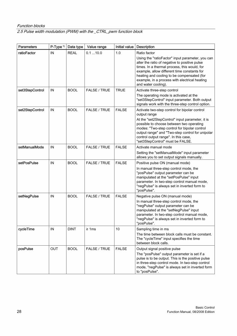
Parameters P-Type 1) Data type Value range Initial value Description ratioFactor IN REAL 0.1 ...10.0 1.0 Ratio factor
Using the "ratioFactor" input parameter, you can alter the ratio of negative to positive pulse times. In a thermal process, this would, for example, allow different time constants for heating and cooling to be compensated (for example, in a process with electrical heating and water cooling).
set3StepControl IN BOOL FALSE / TRUE TRUE Activate three-step control The operating mode is activated at the "set3StepControl" input parameter. Both output signals work with the three-step control option.
set2StepControl IN BOOL FALSE / TRUE FALSE Activate two-step control for bipolar control output range At the "set2StepControl" input parameter, it is possible to choose between two operating modes: "Two-step control for bipolar control output range" and "Two-step control for unipolar control output range". In this case, "set3StepControl" must be FALSE.
setManualMode IN BOOL FALSE / TRUE FALSE Activate manual mode Setting the "setManualMode" input parameter allows you to set output signals manually.
setPosPulse IN BOOL FALSE / TRUE FALSE Positive pulse ON (manual mode) In manual three-step control mode, the "posPulse" output parameter can be manipulated at the "setPosPulse" input parameter. In two-step control manual mode, "negPulse" is always set in inverted form to "posPulse".
setNegPulse IN BOOL FALSE / TRUE FALSE Negative pulse ON (manual mode) In manual three-step control mode, the "negPulse" output parameter can be manipulated at the "setNegPulse" input parameter. In two-step control manual mode, "negPulse" is always set in inverted form to "posPulse".
cycleTime IN DINT ≥ 1ms 10 Sampling time in ms The time between block calls must be constant. The "cycleTime" input specifies the time between block calls.
posPulse OUT BOOL FALSE / TRUE FALSE Output signal positive pulse The "posPulse" output parameter is set if a pulse is to be output. This is the positive pulse in three-step control mode. In two-step control mode, "negPulse" is always set in inverted form to "posPulse".
Function blocks 2.5 Pulse width modulation (PWM) with the _CTRL_pwm function block
Basic Control Function Manual, 08/2008 Edition 29
Parameters P-Type 1) Data type Value range Initial value Description negPulse OUT BOOL FALSE / TRUE FALSE Output signal negative pulse
The "negPulse" output parameter is set if a pulse is to be output. This is the negative pulse in three-step control mode. In two-step control mode, "negPulse" is always set in inverted form to "posPulse".
1) Parameter types: IN = input parameter, OUT = output parameter
Note The value of input parameters is not limited in the block; no parameterization check is performed.
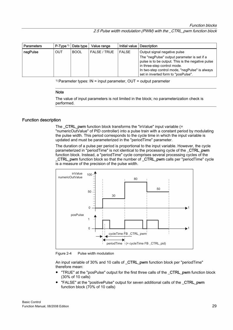
Function description The _CTRL_pwm function block transforms the "inValue" input variable (= "numericOutValue" of PID controller) into a pulse train with a constant period by modulating the pulse width. This period corresponds to the cycle time in which the input variable is updated and must be parameterized in the "periodTime" parameter. The duration of a pulse per period is proportional to the input variable. However, the cycle parameterized in "periodTime" is not identical to the processing cycle of the _CTRL_pwm function block. Instead, a "periodTime" cycle comprises several processing cycles of the _CTRL_pwm function block so that the number of _CTRL_pwm calls per "periodTime" cycle is a measure of the precision of the pulse width.
Figure 2-4 Pulse width modulation
An input variable of 30% and 10 calls of _CTRL_pwm function block per "periodTime" therefore mean: ● "TRUE" at the "posPulse" output for the first three calls of the _CTRL_pwm function block
(30% of 10 calls) ● "FALSE" at the "positivePulse" output for seven additional calls of the _CTRL_pwm
function block (70% of 10 calls)
Function blocks 2.5 Pulse width modulation (PWM) with the _CTRL_pwm function block
Basic Control 30 Function Manual, 08/2008 Edition
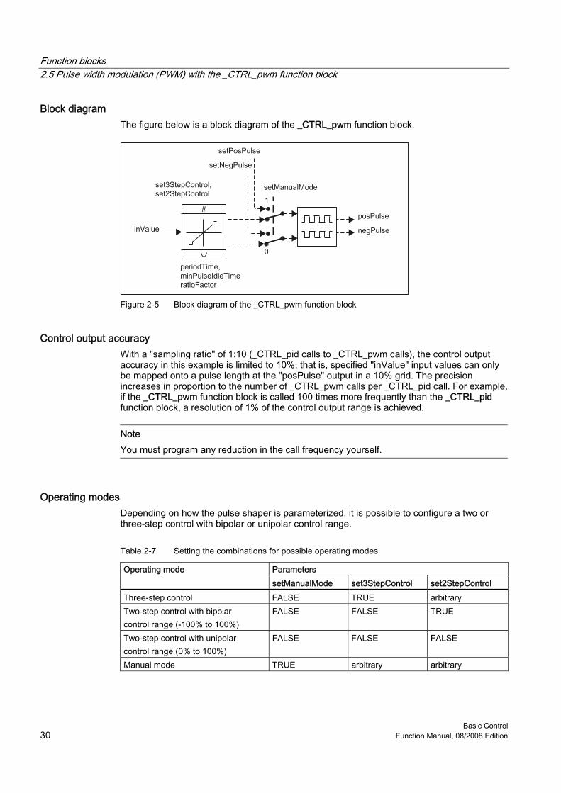
Block diagram The figure below is a block diagram of the _CTRL_pwm function block.
Figure 2-5 Block diagram of the _CTRL_pwm function block
Control output accuracy With a "sampling ratio" of 1:10 (_CTRL_pid calls to _CTRL_pwm calls), the control output accuracy in this example is limited to 10%, that is, specified "inValue" input values can only be mapped onto a pulse length at the "posPulse" output in a 10% grid. The precision increases in proportion to the number of _CTRL_pwm calls per _CTRL_pid call. For example, if the _CTRL_pwm function block is called 100 times more frequently than the _CTRL_pid function block, a resolution of 1% of the control output range is achieved.
Note You must program any reduction in the call frequency yourself.
Operating modes Depending on how the pulse shaper is parameterized, it is possible to configure a two or three-step control with bipolar or unipolar control range.
Table 2-7 Setting the combinations for possible operating modes
Parameters Operating mode setManualMode set3StepControl set2StepControl
Three-step control FALSE TRUE arbitrary Two-step control with bipolar control range (-100% to 100%)
FALSE FALSE TRUE
Two-step control with unipolar control range (0% to 100%)
FALSE FALSE FALSE
Manual mode TRUE arbitrary arbitrary
Function blocks 2.5 Pulse width modulation (PWM) with the _CTRL_pwm function block
Basic Control Function Manual, 08/2008 Edition 31
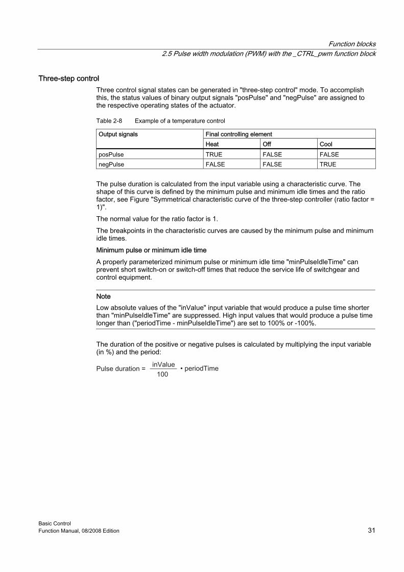
Three-step control Three control signal states can be generated in "three-step control" mode. To accomplish this, the status values of binary output signals "posPulse" and "negPulse" are assigned to the respective operating states of the actuator.
Table 2-8 Example of a temperature control
Final controlling element Output signals Heat Off Cool
posPulse TRUE FALSE FALSE negPulse FALSE FALSE TRUE
The pulse duration is calculated from the input variable using a characteristic curve. The shape of this curve is defined by the minimum pulse and minimum idle times and the ratio factor, see Figure "Symmetrical characteristic curve of the three-step controller (ratio factor = 1)". The normal value for the ratio factor is 1. The breakpoints in the characteristic curves are caused by the minimum pulse and minimum idle times. Minimum pulse or minimum idle time A properly parameterized minimum pulse or minimum idle time "minPulseIdleTime" can prevent short switch-on or switch-off times that reduce the service life of switchgear and control equipment.
Note Low absolute values of the "inValue" input variable that would produce a pulse time shorter than "minPulseIdleTime" are suppressed. High input values that would produce a pulse time longer than ("periodTime - minPulseIdleTime") are set to 100% or -100%.
The duration of the positive or negative pulses is calculated by multiplying the input variable (in %) and the period:
Function blocks 2.5 Pulse width modulation (PWM) with the _CTRL_pwm function block
Basic Control 32 Function Manual, 08/2008 Edition
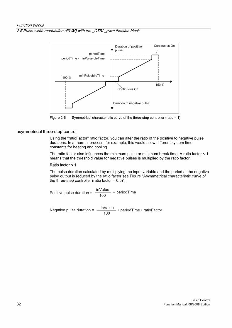
Figure 2-6 Symmetrical characteristic curve of the three-step controller (ratio = 1)
asymmetrical three-step control Using the "ratioFactor" ratio factor, you can alter the ratio of the positive to negative pulse durations. In a thermal process, for example, this would allow different system time constants for heating and cooling. The ratio factor also influences the minimum pulse or minimum break time. A ratio factor < 1 means that the threshold value for negative pulses is multiplied by the ratio factor. Ratio factor < 1 The pulse duration calculated by multiplying the input variable and the period at the negative pulse output is reduced by the ratio factor,see Figure "Asymmetrical characteristic curve of the three-step controller (ratio factor = 0.5)".
•
Function blocks 2.5 Pulse width modulation (PWM) with the _CTRL_pwm function block
Basic Control Function Manual, 08/2008 Edition 33
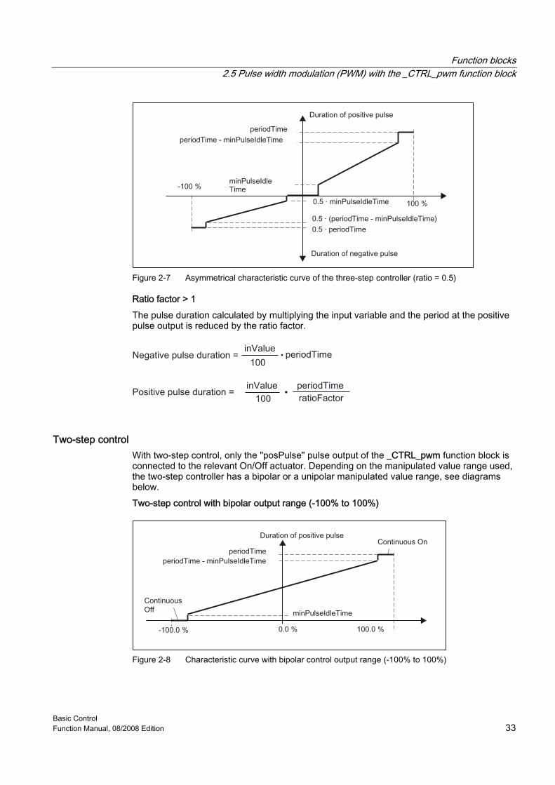
Figure 2-7 Asymmetrical characteristic curve of the three-step controller (ratio = 0.5)
Ratio factor > 1 The pulse duration calculated by multiplying the input variable and the period at the positive pulse output is reduced by the ratio factor.
•
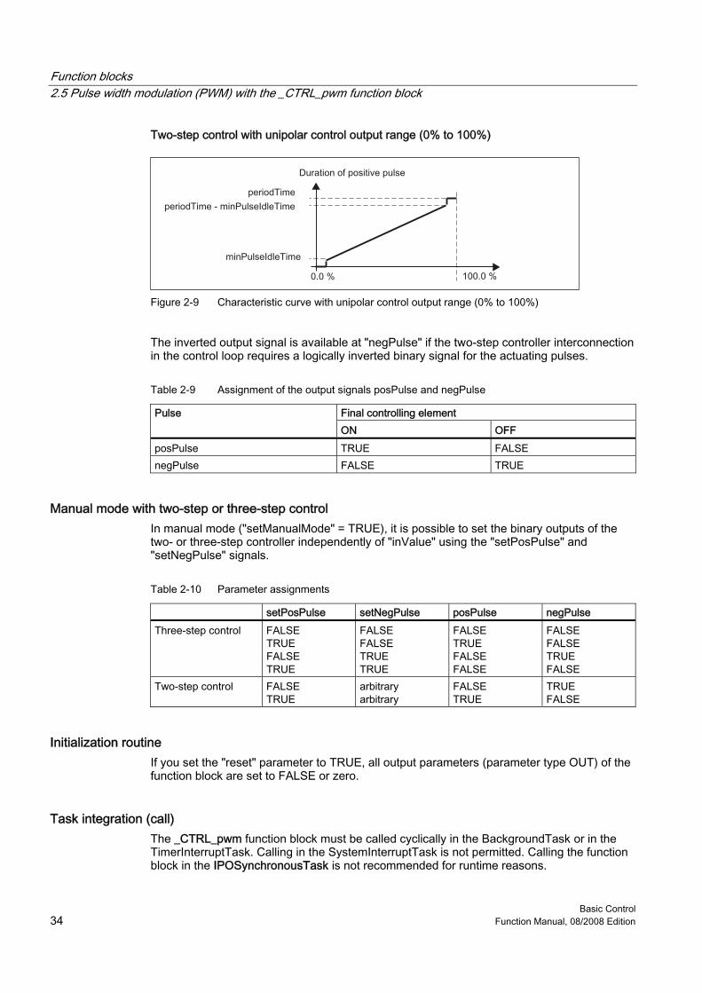
Two-step control With two-step control, only the "posPulse" pulse output of the _CTRL_pwm function block is connected to the relevant On/Off actuator. Depending on the manipulated value range used, the two-step controller has a bipolar or a unipolar manipulated value range, see diagrams below. Two-step control with bipolar output range (-100% to 100%)
Figure 2-8 Characteristic curve with bipolar control output range (-100% to 100%)
Function blocks 2.5 Pulse width modulation (PWM) with the _CTRL_pwm function block
Basic Control 34 Function Manual, 08/2008 Edition
Two-step control with unipolar control output range (0% to 100%)
Figure 2-9 Characteristic curve with unipolar control output range (0% to 100%)
The inverted output signal is available at "negPulse" if the two-step controller interconnection in the control loop requires a logically inverted binary signal for the actuating pulses.
Table 2-9 Assignment of the output signals posPulse and negPulse
Final controlling element Pulse ON OFF
posPulse TRUE FALSE negPulse FALSE TRUE
Manual mode with two-step or three-step control In manual mode ("setManualMode" = TRUE), it is possible to set the binary outputs of the two- or three-step controller independently of "inValue" using the "setPosPulse" and "setNegPulse" signals.
Table 2-10 Parameter assignments
setPosPulse setNegPulse posPulse negPulse Three-step control FALSE
TRUE FALSE TRUE
FALSE FALSE TRUE TRUE
FALSE TRUE FALSE FALSE
FALSE FALSE TRUE FALSE
Two-step control FALSE TRUE
arbitrary arbitrary
FALSE TRUE
TRUE FALSE
Initialization routine If you set the "reset" parameter to TRUE, all output parameters (parameter type OUT) of the function block are set to FALSE or zero.
Task integration (call) The _CTRL_pwm function block must be called cyclically in the BackgroundTask or in the TimerInterruptTask. Calling in the SystemInterruptTask is not permitted. Calling the function block in the IPOSynchronousTask is not recommended for runtime reasons.
Function blocks 2.6 Calling function blocks
Basic Control Function Manual, 08/2008 Edition 35
2.6 2.6 Calling function blocks In order to be able to work with the function blocks in your user program, proceed as follows (The numbers shown in the following program segment correspond to the steps below.): 1. Create the function block instance (see the following program segment, e.g. create
instance for the _CTRL_pid function block). 2. Set up variables for the data structure. 3. Call instance of the function block. 4. Transfer input parameters. 5. The output parameters of the function block are accessed with <instance name of
FB>.<name of output parameter>.
Function blocks 2.6 Calling function blocks
Basic Control 36 Function Manual, 08/2008 Edition
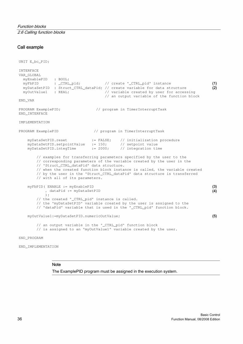
Call example UNIT E_bc_PID; INTERFACE VAR_GLOBAL myEnablePID : BOOL;
myFbPID : _CTRL_pid; // create "_CTRL_pid" instance (1) myDataSetPID : Struct_CTRL_dataPid; // create variable for data structure myOutValue1 : REAL; // variable created by user for accessing // an output variable of the function block
(2)
END_VAR PROGRAM ExamplePID; // program in TimerInterruptTask END_INTERFACE
IMPLEMENTATION PROGRAM ExamplePID // program in TimerInterruptTask myDataSetPID.reset := FALSE; // initialization procedure myDataSetPID.setpointValue := 150; // setpoint value myDataSetPID.integTime := 2000; // integration time
// examples for transferring parameters specified by the user to the // corresponding parameters of the variable created by the user in the // "Struct_CTRL_dataPid" data structure. // when the created function block instance is called, the variable created // by the user in the "Struct_CTRL_dataPid" data structure is transferred // with all of its parameters.
myFbPID( ENABLE := myEnablePID , dataPid := myDataSetPID );
(3) (4)
// the created "_CTRL_pid" instance is called. // the "myDataSetPID" variable created by the user is assigned to the // "dataPid" variable that is used in the "_CTRL_pid" function block.
myOutValue1:=myDataSetPID.numericOutValue; (5) // an output variable in the "_CTRL_pid" function block // is assigned to an "myOutValue1" variable created by the user.
END_PROGRAM END_IMPLEMENTATION
Note The ExamplePID program must be assigned in the execution system.
Basic Control Function Manual, 08/2008 Edition 37
Application example 33.1 3.1 Application example
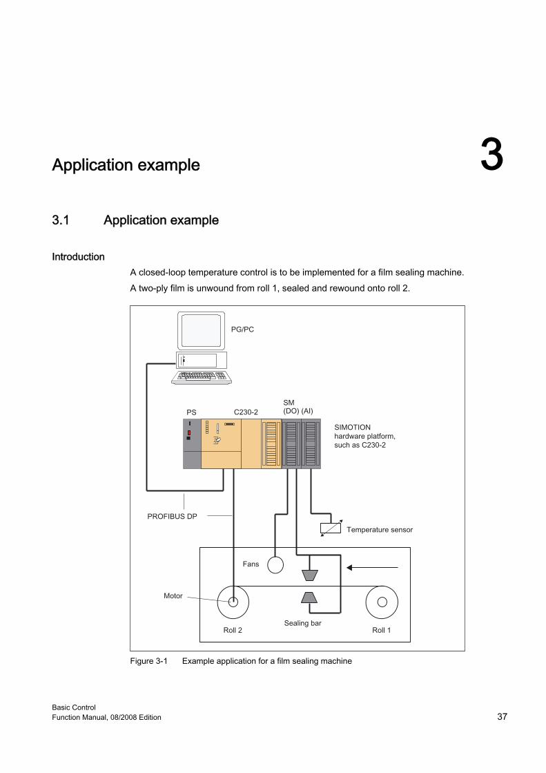
Introduction A closed-loop temperature control is to be implemented for a film sealing machine. A two-ply film is unwound from roll 1, sealed and rewound onto roll 2.
Figure 3-1 Example application for a film sealing machine
Application example 3.1 Application example
Basic Control 38 Function Manual, 08/2008 Edition
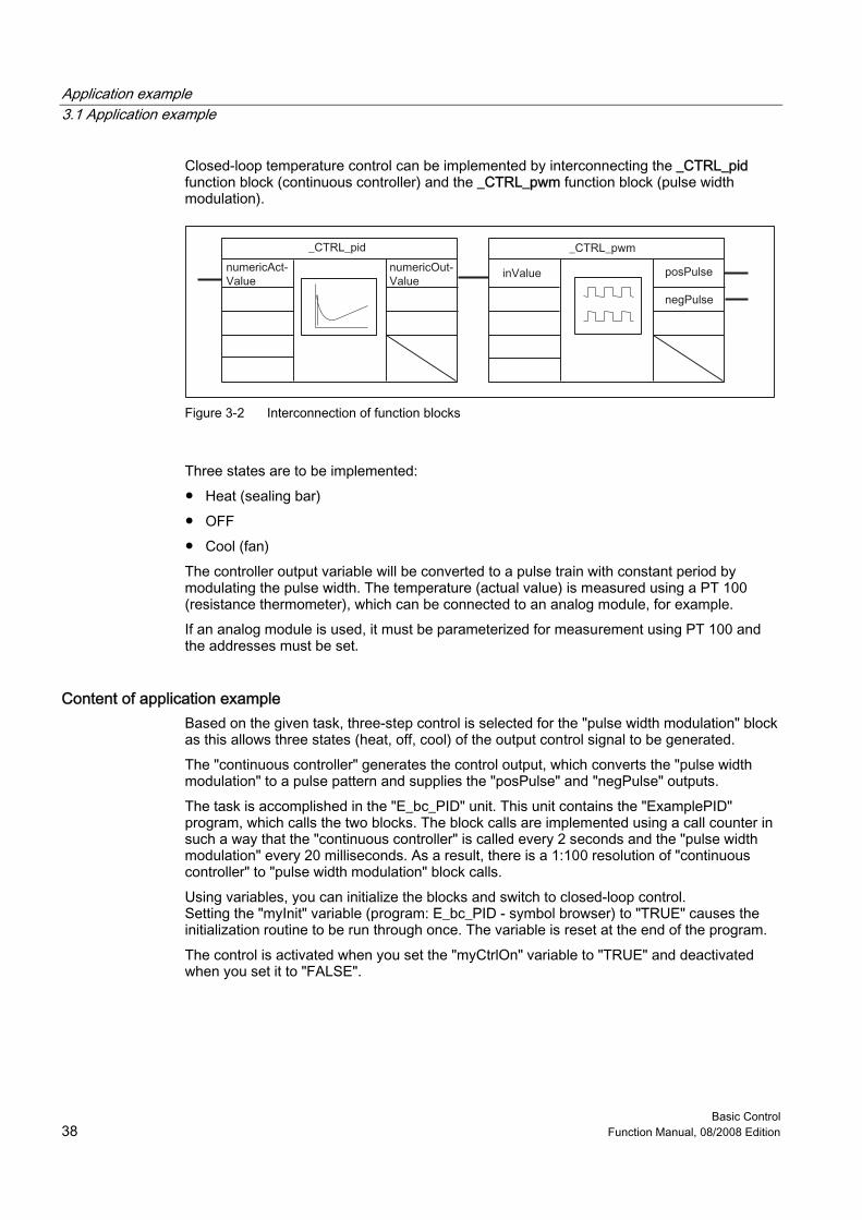
Closed-loop temperature control can be implemented by interconnecting the _CTRL_pid function block (continuous controller) and the _CTRL_pwm function block (pulse width modulation).
Figure 3-2 Interconnection of function blocks
Three states are to be implemented: ● Heat (sealing bar) ● OFF ● Cool (fan) The controller output variable will be converted to a pulse train with constant period by modulating the pulse width. The temperature (actual value) is measured using a PT 100 (resistance thermometer), which can be connected to an analog module, for example. If an analog module is used, it must be parameterized for measurement using PT 100 and the addresses must be set.
Content of application example Based on the given task, three-step control is selected for the "pulse width modulation" block as this allows three states (heat, off, cool) of the output control signal to be generated. The "continuous controller" generates the control output, which converts the "pulse width modulation" to a pulse pattern and supplies the "posPulse" and "negPulse" outputs. The task is accomplished in the "E_bc_PID" unit. This unit contains the "ExamplePID" program, which calls the two blocks. The block calls are implemented using a call counter in such a way that the "continuous controller" is called every 2 seconds and the "pulse width modulation" every 20 milliseconds. As a result, there is a 1:100 resolution of "continuous controller" to "pulse width modulation" block calls. Using variables, you can initialize the blocks and switch to closed-loop control. Setting the "myInit" variable (program: E_bc_PID - symbol browser) to "TRUE" causes the initialization routine to be run through once. The variable is reset at the end of the program. The control is activated when you set the "myCtrlOn" variable to "TRUE" and deactivated when you set it to "FALSE".
Application example 3.1 Application example
Basic Control Function Manual, 08/2008 Edition 39
The "myInTemperature" variable is used symbolically as an input address. It is an INTEGER data type. It may be necessary to convert the actual temperature value to data type INTEGER (for example, from WORD to INT). The "myInTemperature" variable is assigned to the "myInValue" variable. The "myInValue" variable is assigned to the "myDataSetPID.numericActValue" parameter when the instance created of the _CTRL_pid function block is called. The preassignment of the other input parameters of the instances created of the _CTRL_pid function block or the _CTRL_pwm function block, see Table "Preassigned parameters of the _CTRL_pid function block" and Table "Preassigned parameters of the _CTRL_pwm function block". Heater and fan operation is controlled by relays. Each of these is connected to a hardware output. In the example, the "myOutHeating" variable is used symbolically as the output address for heating and the "myOutCooling" variable for the fan. The myDataSetPWM.posPulse and myDataSetPWM.negPulse parameters of the instance created of the _CTRL_pwm function block are assigned to the "myOutValueHeating" and "myOutValueCooling" variables, respectively. The "myOutHeating" and "myOutCooling" variables are assigned to the "myOutValueHeating" and "myOutValueCooling" variables, respectively. The "myDataSetPID.numericOutValue" output parameter of the instance created of the _CTRL_pid function block must first be normalized to between 0 and 100% and then adapted to the three-step control of the _CTRL_pwm function block ("normalizedOutValuePID" variable). The "normalizedOutValuePID" variable is assigned to the "myDataSetPWM.inValue" parameter when the instance created of the _CTRL_pwm function block is called. Because the cycle time of the blocks is required for internal block calculations, the "ExamplePID" program must run in a time-triggered task. The cycle time of this task must match the cycle time of the _CTRL_pwm function block.
Note The real addresses are dependent on the hardware configuration of the relevant machine.
Hardware platform The application example is available for various SIMOTION hardware platforms.
Note If the application example is not available for your hardware platform, you must adapt the hardware configuration.
Adapting the application example The configuration in the example and its available hardware must be adapted. The following options are available: 1. You can adapt the configuration in the example to the available hardware (insert
digital/analog module, assign parameters, and set addresses). 2. You can simulate actual value acquisition and control of output variables (heating and
cooling). Operator control and monitoring using the symbol browser.
Application example 3.1 Application example
Basic Control 40 Function Manual, 08/2008 Edition
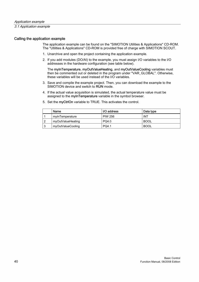
Calling the application example The application example can be found on the "SIMOTION Utilities & Applications" CD-ROM. The "Utilities & Applications" CD-ROM is provided free of charge with SIMOTION SCOUT. 1. Unarchive and open the project containing the application example. 2. If you add modules (DO/AI) to the example, you must assign I/O variables to the I/O
addresses in the hardware configuration (see table below). The myInTemperature, myOutValueHeating, and myOutValueCooling variables must then be commented out or deleted in the program under "VAR_GLOBAL". Otherwise, these variables will be used instead of the I/O variables.
3. Save and compile the example project. Then, you can download the example to the SIMOTION device and switch to RUN mode.
4. If the actual value acquisition is simulated, the actual temperature value must be assigned to the myInTemperature variable in the symbol browser.
5. Set the myCtrlOn variable to TRUE. This activates the control.
Name I/O address Data type 1 myInTemperature PIW 256 INT 2 myOutValueHeating PQ4.0 BOOL 3 myOutValueCooling PQ4.1 BOOL
Application example 3.2 Variables used and preassignments
Basic Control Function Manual, 08/2008 Edition 41
3.2 3.2 Variables used and preassignments
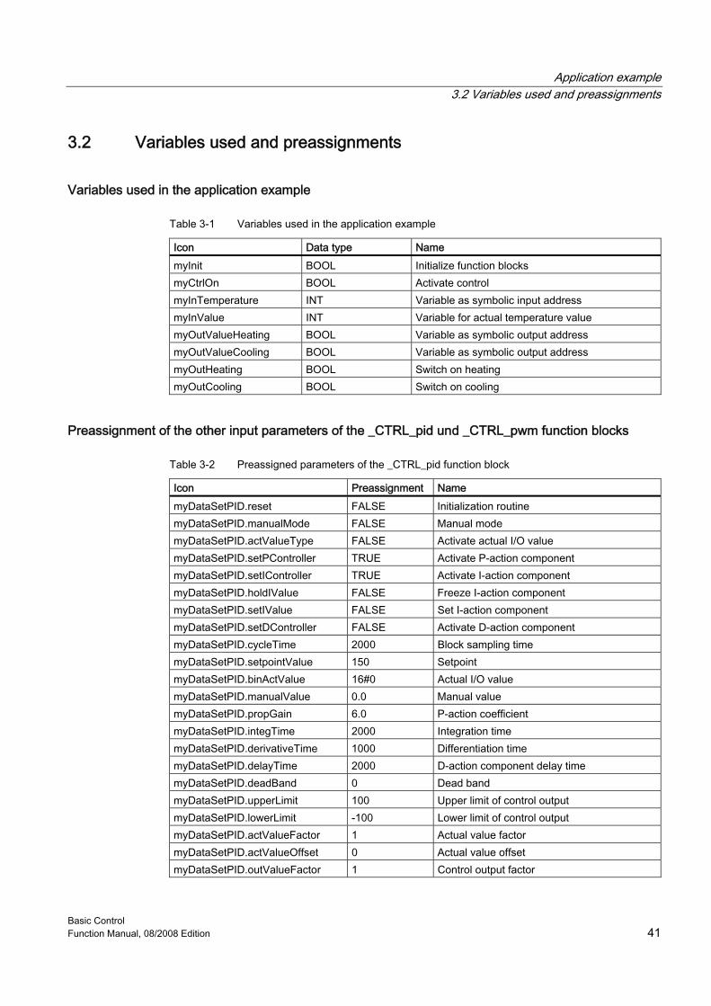
Variables used in the application example
Table 3-1 Variables used in the application example
Icon Data type Name myInit BOOL Initialize function blocks myCtrlOn BOOL Activate control myInTemperature INT Variable as symbolic input address myInValue INT Variable for actual temperature value myOutValueHeating BOOL Variable as symbolic output address myOutValueCooling BOOL Variable as symbolic output address myOutHeating BOOL Switch on heating myOutCooling BOOL Switch on cooling
Preassignment of the other input parameters of the _CTRL_pid und _CTRL_pwm function blocks
Table 3-2 Preassigned parameters of the _CTRL_pid function block
Icon Preassignment Name myDataSetPID.reset FALSE Initialization routine myDataSetPID.manualMode FALSE Manual mode myDataSetPID.actValueType FALSE Activate actual I/O value myDataSetPID.setPController TRUE Activate P-action component myDataSetPID.setIController TRUE Activate I-action component myDataSetPID.holdIValue FALSE Freeze I-action component myDataSetPID.setIValue FALSE Set I-action component myDataSetPID.setDController FALSE Activate D-action component myDataSetPID.cycleTime 2000 Block sampling time myDataSetPID.setpointValue 150 Setpoint myDataSetPID.binActValue 16#0 Actual I/O value myDataSetPID.manualValue 0.0 Manual value myDataSetPID.propGain 6.0 P-action coefficient myDataSetPID.integTime 2000 Integration time myDataSetPID.derivativeTime 1000 Differentiation time myDataSetPID.delayTime 2000 D-action component delay time myDataSetPID.deadBand 0 Dead band myDataSetPID.upperLimit 100 Upper limit of control output myDataSetPID.lowerLimit -100 Lower limit of control output myDataSetPID.actValueFactor 1 Actual value factor myDataSetPID.actValueOffset 0 Actual value offset myDataSetPID.outValueFactor 1 Control output factor
Application example 3.2 Variables used and preassignments
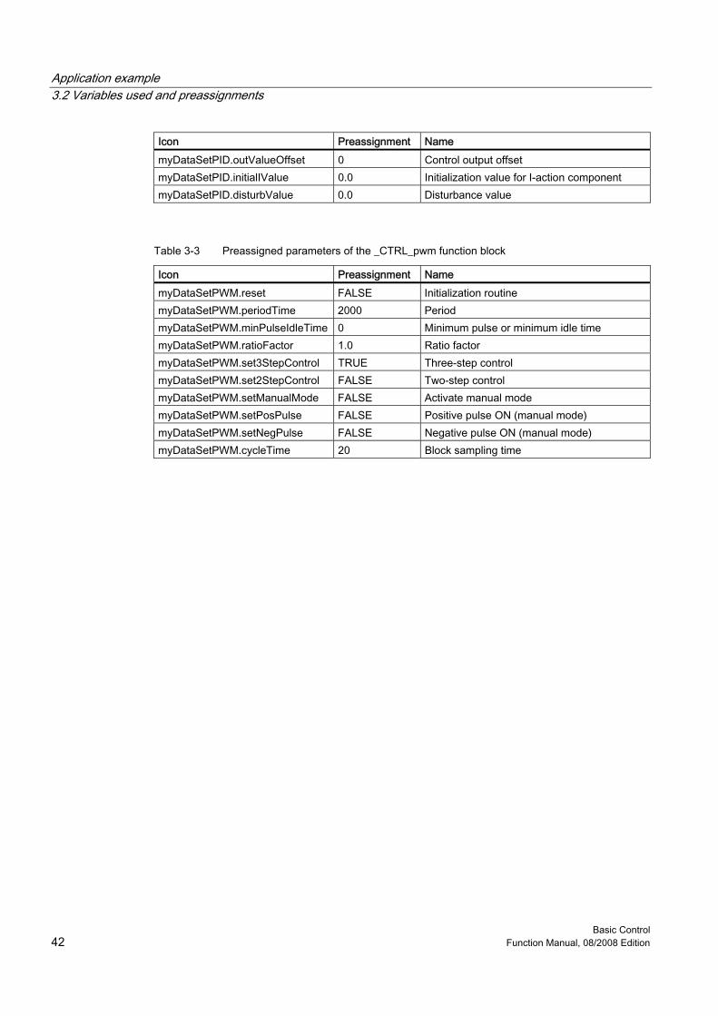
Basic Control 42 Function Manual, 08/2008 Edition
Icon Preassignment Name myDataSetPID.outValueOffset 0 Control output offset myDataSetPID.initialIValue 0.0 Initialization value for I-action component myDataSetPID.disturbValue 0.0 Disturbance value
Table 3-3 Preassigned parameters of the _CTRL_pwm function block
Icon Preassignment Name myDataSetPWM.reset FALSE Initialization routine myDataSetPWM.periodTime 2000 Period myDataSetPWM.minPulseIdleTime 0 Minimum pulse or minimum idle time myDataSetPWM.ratioFactor 1.0 Ratio factor myDataSetPWM.set3StepControl TRUE Three-step control myDataSetPWM.set2StepControl FALSE Two-step control myDataSetPWM.setManualMode FALSE Activate manual mode myDataSetPWM.setPosPulse FALSE Positive pulse ON (manual mode) myDataSetPWM.setNegPulse FALSE Negative pulse ON (manual mode) myDataSetPWM.cycleTime 20 Block sampling time
Basic Control Function Manual, 08/2008 Edition 43
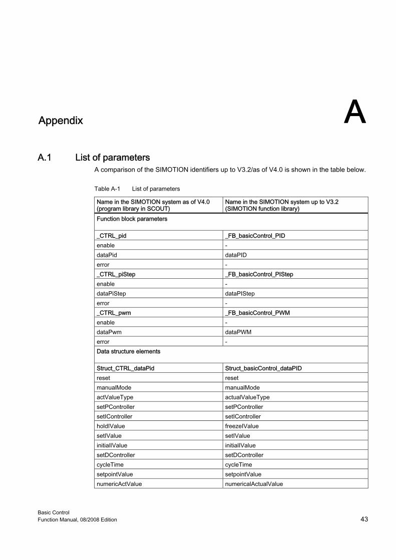
A Appendix AA.1 A.1 List of parameters
A comparison of the SIMOTION identifiers up to V3.2/as of V4.0 is shown in the table below.
Table A-1 List of parameters
Name in the SIMOTION system as of V4.0 (program library in SCOUT)
Name in the SIMOTION system up to V3.2 (SIMOTION function library)
Function block parameters _CTRL_pid _FB_basicControl_PID enable - dataPid dataPID error - _CTRL_piStep _FB_basicControl_PIStep enable - dataPiStep dataPIStep error - _CTRL_pwm _FB_basicControl_PWM enable - dataPwm dataPWM error - Data structure elements Struct_CTRL_dataPid Struct_basicControl_dataPID reset reset manualMode manualMode actValueType actualValueType setPController setPController setIController setIController holdIValue freezeIValue setIValue setIValue initialIValue initialIValue setDController setDController cycleTime cycleTime setpointValue setpointValue numericActValue numericalActualValue

Appendix A.1 List of parameters
Basic Control 44 Function Manual, 08/2008 Edition
Name in the SIMOTION system as of V4.0 (program library in SCOUT)
Name in the SIMOTION system up to V3.2 (SIMOTION function library)
binActValue binaryActualValue manualValue manualValue propGain proportionalGain integTime integrationTime derivativeTime derivativeTime delayTime delayTime deadBand deadBand upperLimit upperLimit lowerLimit lowerLimit actValueFactor actualValueFactor actValueOffset actualValueOffset outValueFactor outputValueFactor outValueOffset outputValueOffset disturbValue disturbanceValue numericOutValue numericalOutputValue binOutValue binaryOutputValue upperLimitReached upperLimitReached lowerLimitReached lowerLimitReached POutValue POutputValue IOutValue IOutputValue DOutValue DOutputValue actValue actualValue deviationValue deviationValue Struct_CTRL_dataPiStep Struct_basicControl_dataPIStep reset reset actValueType actualValueType cycleTime cycleTime setpointValue setpointValue numericActValue numericalActualValue binActValue binaryActualValue propGain proportionalGain integTime integrationTime deadBand deadBand upperLimit upperLimit lowerLimit lowerLimit manualMode manualMode setOutHigh setOutputHigh setOutLow setOutputLow minPulseTime minPulseTime minIdleTime minIdleTime actuatingTime actuatingTime
Appendix A.1 List of parameters
Basic Control Function Manual, 08/2008 Edition 45
Name in the SIMOTION system as of V4.0 (program library in SCOUT)
Name in the SIMOTION system up to V3.2 (SIMOTION function library)
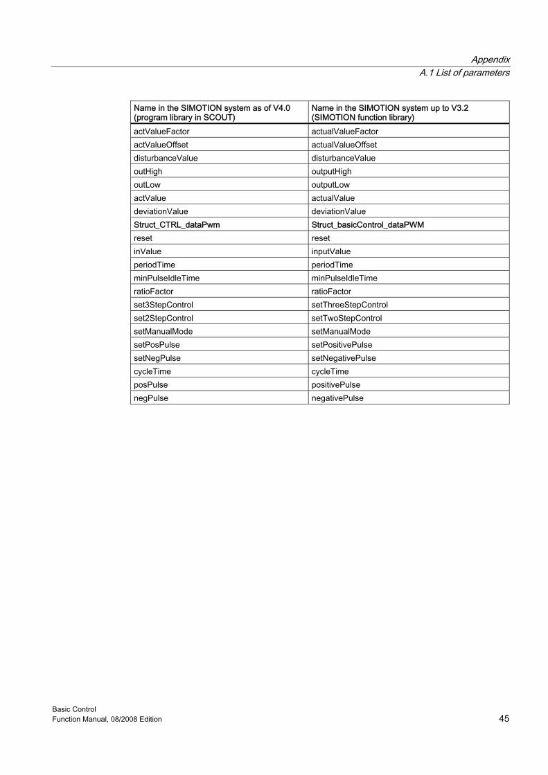
actValueFactor actualValueFactor actValueOffset actualValueOffset disturbanceValue disturbanceValue outHigh outputHigh outLow outputLow actValue actualValue deviationValue deviationValue Struct_CTRL_dataPwm Struct_basicControl_dataPWM reset reset inValue inputValue periodTime periodTime minPulseIdleTime minPulseIdleTime ratioFactor ratioFactor set3StepControl setThreeStepControl set2StepControl setTwoStepControl setManualMode setManualMode setPosPulse setPositivePulse setNegPulse setNegativePulse cycleTime cycleTime posPulse positivePulse negPulse negativePulse
Appendix A.2 List of abbreviations
Basic Control 46 Function Manual, 08/2008 Edition
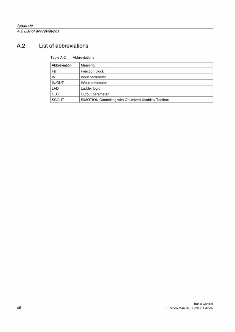
A.2 A.2 List of abbreviations
Table A-2 Abbreviations
Abbreviation Meaning FB Function block IN Input parameter IN/OUT In/out parameter LAD Ladder logic OUT Output parameter SCOUT SIMOTION Controlling with Optimized Usability Toolbox
Basic Control Function Manual, 08/2008 Edition 47
Index
_ _CTRL_pid function block parameters, 13
A Application example, 37
B Basic Control
Overview, 9 Block diagram
FB _CTRL_pid, 19 FB _CTRL_piStep, 25 FB _CTRL_pwm, 30
C Calling function blocks, 35 Continuous control, 9 Controlled system analysis, 10 Controller selection, 10
D Data structure of PID controller, 14 Data structure of PI-step controller, 21 Data structure of pulse width modulation, 27
F FB _CTRL_pid, 13
Block diagram, 19 Data structure, 14 Parameter description, 13
FB _CTRL_piStep, 20 Block diagram, 25 Data structure, 21 Parameter description, 20
FB _CTRL_pwm, 26
asymmetrical three-step control, 32 Block diagram, 30 Data structure, 27 Parameter description, 26 Three-step control, 31 Two-step control, 33
Function blocks _CTRL_pid, 13 _CTRL_piStep, 20 _CTRL_pwm, 26 Task integration, 19, 25, 34
I Integrating the function blocks, 12
L List of parameters, 43
P Parameters of the _CTRL_piStep function block, 20 Parameters of the _CTRL_pwm function block, 26 Possible applications, 10 Pulse shapes with the _CTRL_pwm function block, 26 Pulse width modulation, 9
R References, 3
S Step closed-loop control, 9 Step control using the _CTRL_piStep function block, 20
T Task integration, 19, 25, 34