sinamics / simotion / sinumerik / simotics - siemens · sinamics / simotion / sinumerik / simotics...
TRANSCRIPT

Unrestricted
SINAMICS / SIMOTION / SINUMERIK / SIMOTICS Safety Integrated functions
Probability of failure
of Safety Integrated functions

Probability of failure SINAMICS UnrestrictedRevision V1.6, 01/2018 2/49
Cop
yrig
ht
Sie
me
ns A
G 2
018
All
righ
ts r
eser
ved.
Table of contents
1 Introduction ..........................................................................................3
2 Probability of failure .............................................................................4 2.1 Basic information .................................................................................4 2.2 Calculating subsystem PFH or PFD values .........................................5 2.3 Supplementary conditions ...................................................................6
3 Safety-related parameters for SINAMICS ............................................6 3.1 SINAMICS G110M ..............................................................................7 3.2 SINAMICS G120 modular....................................................................8 3.3 SINAMICS G120C ............................................................................. 10 3.4 SINAMICS G120D ............................................................................. 11 3.5 SINAMICS G120P ............................................................................. 12 3.6 SINAMICS G130 ............................................................................... 15 3.7 SINAMICS G150 ............................................................................... 17 3.8 SINAMICS G180 ............................................................................... 19 3.9 SINAMICS V90 .................................................................................. 21 3.10 SINAMICS S110 ................................................................................ 22 3.11 SINAMICS S120 AC/AC .................................................................... 24 3.12 SINAMICS S120 chassis units .......................................................... 26 3.13 SINAMICS S120 Cabinet Modules .................................................... 30 3.14 SINAMICS S150 ................................................................................ 33 3.15 SINAMICS S210 ................................................................................ 35
4 Safety-related parameters for SIMOTICS .......................................... 36 4.1 Motors with encoder connection ........................................................ 36
5 Safety-related parameters for SIMOTION ......................................... 38
6 Safety-related parameters for SINUMERIK ....................................... 41 6.1 SINUMERIK 840D sl ......................................................................... 41 6.2 SINUMERIK 828D ............................................................................. 45 6.3 SINUMERIK 840D with SIMODRIVE 611D ....................................... 47 6.4 SINUMERIK handheld units .............................................................. 47 6.5 SINUMERIK machine control panel ................................................... 48
7 Calculation using the Safety Evaluation Tool ..................................... 49
8 Terminology / abbreviations ............................................................... 49
9 History ............................................................................................... 49

Probability of failure SINAMICS UnrestrictedRevision V1.6, 01/2018 3/49
Cop
yrig
ht
Sie
me
ns A
G 2
018
All
righ
ts r
eser
ved.
1 Introduction
This document is not independent; it may only be used as a supplement to the "SINUMERIK 828D / SINAMICS S120 Safety Integrated", "SINUMERIK 840D sl / SINAMICS S120 Safety Integrated", "SINAMICS S120 Safety Integrated" or "SINAMICS G120 Safety Integrated" Function Manuals.
"Safety Integrated" functions are used to reduce risks dependent on the application. Functional safety means that safety is achieved by the safety function operating as it should. The products are intended for installation in machines. The manuals can be ordered through your local Siemens office and can be downloaded from the Internet as PDF http://www.siemens.com/automation/service&support.
The danger notices must be observed.
In particular, the general lists of components, including those from different device families, must not be used to draw conclusions about permissible combinations of such components. Information about permissible component combinations can only be taken from the device-specific documentation. The most recent version of this document must always be used to calculate the PFH value of a (sub)system.
Further information concerning SINAMICS Safety Integrated you will find:
http://www.siemens.com/safety-drives

Probability of failure SINAMICS UnrestrictedRevision V1.6, 01/2018 4/49
Cop
yrig
ht
Sie
me
ns A
G 2
018
All
righ
ts r
eser
ved.
2 Probability of failure
2.1 Basic information
The safety-related parameters for safety functions integrated in the SINAMICS, SIMOTION, SINUMERIK and SIMOTICS systems will be discussed in this document.
The SINUMERIK, SIMOTION and SINAMICS systems have the following general1) properties:
according to IEC 61508, the following properties are complied with:
o Safety integrity level (SIL) 2
o Mode: "high demand/continuous mode" or
o "low demand mode"
according to ISO 13849-1, the following properties are complied with:
o Category 3
o Performance Level (PL) d
To verify SIL 2 (mode: "high demand/continuous mode") or PL d, the calculated PFH value of the (sub)system being considered must be less than 10-6/h. For SIL 2 in the "low demand mode", the PFD value must be less than 10-2 .
Definitions:
PFH Probability of failures per hour
The PFH value according to IEC 61800-5-2 corresponds to the PFHD value according to IEC 62061.
The PFH value is used for high demand rates or continuous demand.
PFD Mean probability of failure on demand of the safety function corresponds to the PFD value according to IEC 61508.
The PFD value is used for low demand rates.
B10d Number of cycles up until 10% of the components have failed dangerously according to ISO 13849-1
The additional data in the tables in the following chapter are used to explain the functional versions of the components.
The safety-relevant parameters of the individual components are specified in the following chapters. These represent a percentage of the total PFH or PFD value of the safety functions of a plant or machine.
1) Deviations are described at the separate components.

Probability of failure SINAMICS UnrestrictedRevision V1.6, 01/2018 5/49
Cop
yrig
ht
Sie
me
ns A
G 2
018
All
righ
ts r
eser
ved.
The following time data are prerequisites for these values (valid for PFH and PFD):
Mission time 20 years
Maximum diagnostic test interval 1 year
(Maximum diagnostic test interval) Safety-related peripherals and safety-related sensors and actuators have not been taken into account in these examples. The calculations refer solely to the SINAMICS/SINUMERIK/SIMOTION/SIMOTICS components contained in the diagrams. The Safety Evaluation Tool (SET) will then be discussed in the next Chapter 7. You can quickly and reliably assess the safety functions of plants/machines using SET. In addition to the drive/control components listed in this document, SET also includes components for detecting and evaluating from Siemens DF and PD.
2.2 Calculating subsystem PFH or PFD values
For a drive system, all safety-related axes controlled by a Control Unit must be identified first. If more than one Control Unit is in use, the safety-relevant axes must be identified separately and the calculation for each Control Unit must be made separately. For each safety-related axis, the controlling Motor Module/Power Module is relevant from the point of view of safety. In the case of Double Motor Modules, whether the safety functions have been configured for both axes or just for one axis is also important for the PFH/PFD calculation. Where encoderless motion monitoring is concerned, the PFH/PFD value listed in the table must also be taken into account. For 2-encoder safety systems, the specified PFH/PFD value applies to both Sensor Modules involved. For safety systems with 1 encoder, the corresponding PFH/PFD value must be applied as appropriate for the Sensor Module (SMC, SME, or the DRIVE-CLiQ motor being used). The PFH/PFD values of all safety-related components must be added together for the subsystem under consideration (based on their actual number). Further, for SIMOTION and SINUMERIK the following also applies: A CX32 or NX is safety relevant, if at least one of the associated Motor Modules is safety relevant. The NCU is safety relevant if system/drive-integrated safety components according to Chapter 5/6 of the "SINUMERIK Safety Integrated" Function Module are used on at least one of the directly assigned Motor Modules or controlled via NX. If the subsystem being considered only uses the drive-integrated safety functions according to Chapter 4 of the "SINUMERIK 840D sl /SINAMICS S120 Safety Integrated" Function Manual (only drive-integrated STO/SBC/SS1 via terminals), then the NCU is only relevant, if at least one of the associated Motor Modules (i.e. assigned to the internal control of the NCU) is safety relevant. Both application cases have different PFH values.

Probability of failure SINAMICS UnrestrictedRevision V1.6, 01/2018 6/49
Cop
yrig
ht
Sie
me
ns A
G 2
018
All
righ
ts r
eser
ved.
As additional information for handling holding brakes, calculation examples for suspended/hanging (i.e. subject to gravity) axes are listed in the following document:
http://support.automation.siemens.com/WW/view/en/69870640
2.3 Supplementary conditions
The specified failure probabilities only apply under the precondition that the secondary conditions for the diagnostic test (see the Function Manuals), including the diagnostic test interval, are maintained. The PFH/PFD values are only valid up to the specified mission time. The PFH/PFD values are only valid under the precondition that the responses initiated by Safety Integrated in the event of an error (triggering a stop, activation of safe torque off STO, etc.) bring the process into a safe state or maintain the process in a safe state. Please refer to the corresponding manuals for the components used for information about the properties of additional safety-relevant components, such as control systems, sensors and actuators (e.g. Emergency Stop buttons, protective door switches). The PFH/PFD value calculated here only takes the risks posed by the components of the SINAMICS, SIMOTION, SINUMERIK and SIMOTICS systems into account.
3 Safety-related parameters for SINAMICS Only the drive components are taken into account in the following configuration examples. These are shown in boxes in the following diagrams. The corresponding manufacturer's data should be used as basis to evaluate additional components. The Safety Evaluation Tool (SET) is available to evaluate safety systems, see Chapter 7.

Probability of failure SINAMICS UnrestrictedRevision V1.6, 01/2018 7/49
Cop
yrig
ht
Sie
me
ns A
G 2
018
All
righ
ts r
eser
ved.
3.1 SINAMICS G110M
The following values can be applied to the complete converter. G110M supports applications with STO.
Product Order number PFH [10-9/h] PFD [10-4]
CU240M USS/Modbus RTU 6SL3544-xxxxx-xBxx 50 50
CU240M DP 6SL3544-xxxxx-xPxx 50 50
CU240M PN 6SL3544-xxxxx-xFxx 50 50
CU240M AS-i 6SL3544-xxxxx-xMxx 50 50
Table 3-1
Configuration example: The button in this example is directly connected to the F-DI of the converter. Alternatively, this can be connected to the distributed I/O; the signals are then transferred via PROFIsafe.
CU
PM
M3~
Emergency Stop button STO
Safety relevant
Nicht Safety relevant
F-DI
Figure 3-1
Assessment of safety relevance of components and assignment of PFH values:
Subsystem function "Emergency Stop" STO (without Emergency Stop button)
Component Description PFH [10-9/h] CU Control Unit CU240M PN
50PM Power Module PM240M
PFH value of the subsystem or total system 50This system example has a PFH value of 50*10-9/h and fulfills the criteria for SIL 2 and PL d (< 10-6/h).
Table 3-2

Probability of failure SINAMICS UnrestrictedRevision V1.6, 01/2018 8/49
Cop
yrig
ht
Sie
me
ns A
G 2
018
All
righ
ts r
eser
ved.
3.2 SINAMICS G120 modular
The following values can be used for a complete drive train, comprising the Control Unit, Power Module and Safe Brake Relay mentioned here. They are valid for Basic and Extended Functions without encoder.
Product Order number PFH [10-9/h] PFD [10-4]
CU240E-2 6SL3244-0BB12-xxxx 50 50
CU240E-2 F 6SL3244-0BB13-xxxx 50 50
CU240S F 6SL3244-0BA21-xxxx 50 50
CU250S-2 6SL3246-0BA22-xxxx 50 50
Power Module STO SIL3/PLe
PM240-2 Framesize D to F1)
without 5 5
Table 3-3 The Power Module based STO can be used in connection with the Control Units 2nd generation (productlabeling with “-2”) and from firmware version V4.7 SP3. This PM-STO can be used in the following use cases: - Using the PM-STO, the value with the footnote 1) must be considered. - Using the Control Unit based Safety Functions, the CU-based value in table 3-3 must be considered. - Using the Control Unit based Safety Functions and also the PM-STO, both values must be
considered, the CU-based value in table 3-3 and the value with the footnote 1). In deviation to the general basics acording to chapter 2.1, the PM-STO has the following properties:
according to IEC 61508:
o Safety integrity level (SIL) 3 According to ISO 13849-1:
o Category 3 o Performance Level (PL) e
maximum diagnostic test interval: 3 months The verification of SIL3 resp. PLe needs a PFH value smaller than 10-7/h resp. PFD value smaller than 10-3 for the safeyt system. Configuration example: The two buttons in this example are directly connected to the fail-safe digital inputs (F-DI) of the converter. Alternatively, they can be connected to the distributed I/O. The signals are then transferred via PROFIsafe. In this case, the PFH values in the subsystems shown below, should be evaluated in the same way.

Probability of failure SINAMICS UnrestrictedRevision V1.6, 01/2018 9/49
Cop
yrig
ht
Sie
me
ns A
G 2
018
All
righ
ts r
eser
ved.
For standard CUs (not the F-version), applications with STO are supported.
The subsystem Emergency Stop is evaluated in the same way as shown in this example.
Figure 3-2 Assessment of safety relevance of components and assignment of PFH values:
Subsystem function "Emergency Stop" STO (without Emergency Stop button)
Component Description PFH [10-9/h] CU CU240E-2 PN F Control Unit
50PM PM240 Power Module
PFH value of the subsystem or total system 50This system example has a PFH value of 50*10-9/h and fulfills the criteria for SIL 2 and PL d (< 10-6/h). Subsystem function "Setting up operation with limited speed" SLS without encoder (without safety switch) Component Description PFH [10-9/h]
CU CU240E-2 PN F Control Unit 50
PM PM240 Power Module PFH value of the subsystem or total system 50
This system example has a PFH value of 50*10-9/h and fulfills the criteria for SIL 2 and PL d (< 10-6/h).
Table 3-4

Probability of failure SINAMICS UnrestrictedRevision V1.6, 01/2018 10/49
Cop
yrig
ht
Sie
me
ns A
G 2
018
All
righ
ts r
eser
ved.
3.3 SINAMICS G120C
The following values can be applied to the complete converter. G120C supports applications with STO.
Product Order number PFH [10-9/h] PFD [10-4]
G120C USS/Modbus RTU 6SL3210-xxxxx-xxBx 50 50
G120C DP 6SL3210-xxxxx-xxPx 50 50
G120C PN 6SL3210-xxxxx-xxFx 50 50
G120C CAN 6SL3210-xxxxx-xxCx 50 50
Table 3-5
Configuration example: The button in this example is directly connected to the F-DI of the converter. Alternatively, this can be connected to the distributed I/O; the signals are then transferred via PROFIsafe.
Converter
M3~Safety relevant
Non-Safety relevant
F-DI
Emergency Stop button STO
Figure 3-3 Assessment of safety relevance of components and assignment of PFH values:
Subsystem function "Emergency Stop" STO (without Emergency Stop button)
Component Description PFH [10-9/h] Converter G120C 50
PFH value of the subsystem or total system 50This system example has a PFH value of 50*10-9/h and fulfills the criteria for SIL 2 and PL d (< 10-6/h).
Table 3-6

Probability of failure SINAMICS UnrestrictedRevision V1.6, 01/2018 11/49
Cop
yrig
ht
Sie
me
ns A
G 2
018
All
righ
ts r
eser
ved.
3.4 SINAMICS G120D
The following values are for a complete drive train, comprising the Control Unit and Power Module. They are valid for Basic and Extended Functions without encoder.
Product Order number PFH [10-9/h] PFD [10-4]
CU240D –F 6SL3544-0FA21-xxxx 50 50
CU240D-2 6SL3544-0FB20-xxxx 50 50
CU240D-2 –F 6SL3544-0FB21-xxxx 50 50
CU250D-2 –F 6SL3546-0FB21-xxxx 50 50
Table 3-7
For a configuration example, see Chapter 3.1. The structure shown there with the CU and PM components, should be used in the same way for G120D. For standard CUs (not the F-version), applications with STO are supported. The Emergency Stop subsystem is evaluated in the same way as shown in this example.

Probability of failure SINAMICS UnrestrictedRevision V1.6, 01/2018 12/49
Cop
yrig
ht
Sie
me
ns A
G 2
018
All
righ
ts r
eser
ved.
3.5 SINAMICS G120P
The Power Module PM240P-2 and PM330 (from function state FS: 04) provide shutdown pathes for hardware STO. The functions evaluate diagnosis of the sensors, control and diagnosis of the shutdown pathes will be executed by external components, e.g. safety relay or F-PLC. So safety functions STO resp. SS1-t can be realized. The following values are for the Power Module without external system components.
Product Order number PFH [10-9/h] PFD [10-4]
PM240P-2 6SL3210-1Rxxx-xxL0 5 5
PM330 6SL3310-1Pxxx-xAA0 50 50
PM330L 6SL3310-1Cxxx-xAA0 50 50
Table 3-8
Configuration example: In this example the safety relay activates the shutdown pathes of the PM240P-2 and leads the feedback signal for the diagnosis back to the CU230P-2 via digital output.
Figure 3-4

Probability of failure SINAMICS UnrestrictedRevision V1.6, 01/2018 13/49
Cop
yrig
ht
Sie
me
ns A
G 2
018
All
righ
ts r
eser
ved.
Assessment of safety relevance of components and assignment of PFH values:
Component Description PFH [10-9/h] Converter Power Module PM240P-2 5Safety relay z.B. 3SK2112-xAA10 10.0
PFH value of the subsystem or total system 15.0This system example has a PFH value of 15.0*10-9/h and fulfills the criteria for SIL 3 and PL e (< 10-7/h).
Table 3-9
Configuration example:
In this example the safety relay activates the shutdown pathes of the PM330 and executes the diagnosis via feedback signals.
Figure 3-5 Assessment of safety relevance of components and assignment of PFH values: Component Description PFH [10-9/h]
Converter Power Module PM330 50Safety relay e.g. 3SK1121-xAB40 2.5
PFH value of the subsystem or total system 52.5This system example has a PFH value of 52.5*10-9/h and fulfills the criteria for SIL 3 and PL e (< 10-7/h).
Table 3-10

Probability of failure SINAMICS UnrestrictedRevision V1.6, 01/2018 14/49
Cop
yrig
ht
Sie
me
ns A
G 2
018
All
righ
ts r
eser
ved.
The Power Module STO can be used in connection with the Control Unit CU230P-2 from firmware version V4.7 SP6. In deviation to the general basics acording to chapter 2.1, the PM-STO has the following properties:
according to IEC 61508:
o Safety integrity level (SIL) 3 according to ISO 13849-1:
o Category 3 o Performance Level (PL) e
maximum diagnostic test interval: 3 months
The verification of SIL3 resp. PLe needs a PFH value smaller than 10-7/h resp. PFD value smaller than 10-3 for the safeyt system.

Probability of failure SINAMICS UnrestrictedRevision V1.6, 01/2018 15/49
Cop
yrig
ht
Sie
me
ns A
G 2
018
All
righ
ts r
eser
ved.
3.6 SINAMICS G130
The following values can be used for Basic Functions and Extended Functions.
Product Order number PFH [10-9/h] PFD [10-4] Additional details
Control Unit CU320 6SL3040-0MA00-0AA1 10 10 --
Control Unit CU320-2 DP 6SL3040-1MA00-0AA0 10 10 --
Control Unit CU320-2 PN 6SL3040-1MA01-0AA0 10 10 --
Power Module in chassis format 6SL3310-1Gxxx-xxx3 14 14 without SBC Power Module in chassis format 6SL3310-1Gxxx-xxx3 15 15 with SBC
Encoderless motion monitoring without 20 20 --
SMC30 Sensor Module 3SL3055-0AA00-5CAx 100 100 2-encoder system (value is valid for both
Sensor Modules)
Terminal Module TM54F 6SL3055-0AA00-3BA0 38 38 --
Safe Brake Adapter 230V AC
Actuated 1/h 6SL3355-2DX00-1AA0 2 2 for using SBC
Safe Brake Adapter 230V AC
Actuated 1/min 6SL3355-2DX00-1AA0 120 120 for using SBC
Table 3-11
Using the Safe Brake Adapter: The failure rates of the Safe Brake Adapter are dependent on the frequency of actuation. Interpolation proportional to nop is possible between the specified PFH values:
For infrequent actuation, PFHSBA(1/h) is also valid.
The interpolation is also analogously applicable for the PFD value.
Configuration example: The two command devices in this example are directly connected to the (F-DI) of the converter system. Alternatively, they can be connected to the distributed I/O, and the signals are transferred to the drive via PROFIsafe. In this case, the PFH values in the subsystems shown below, should be evaluated in the same way. Note regarding 2-encoder systems: In addition to the motor encoder, a machine encoder or a second motor encoder can be used as second encoder.

Probability of failure SINAMICS UnrestrictedRevision V1.6, 01/2018 16/49
Cop
yrig
ht
Sie
me
ns A
G 2
018
All
righ
ts r
eser
ved.
Figure 3-6 Assessment of safety relevance of components and assignment of PFH values: Subsystem function "Emergency Stop" STO (without Emergency Stop button)
Component Description PFH [10-9/h]
CU Control Unit CU320-2 10PM G130 Power Module Chassis without SBC 14
PFH value of the subsystem or total system 24This system example has a PFH value of 24*10-9/h and fulfills the criteria for SIL 2 and PL d (< 10-6/h). Subsystem function "Setting up operation with limited speed" SLS (without safety switch) Component Description PFH [10-9/h] CU Control Unit CU320-2 10PM G130 Power Module Chassis without SBC 14TM54 F Terminal Module TM54F 38HTL/TTL encoders
2-encoder system with Sensor Modules SMC30 100
PFH value of the subsystem or total system 162This system example has a PFH value of 162*10-9/h and fulfills the criteria for SIL 2 and PL d (< 10-6/h).
Table 3-12

Probability of failure SINAMICS UnrestrictedRevision V1.6, 01/2018 17/49
Cop
yrig
ht
Sie
me
ns A
G 2
018
All
righ
ts r
eser
ved.
3.7 SINAMICS G150
The following values can be used for Basic Functions and Extended Functions.
Product Order number PFH [10-9/h] PFD [10-4] Additional details
Converter
(CU320-2 DP + PM/MM) 6SL3710-1Gxxx-xxx3 24 24 without SBC
Converter, 2x parallel connection
(CU320-2 DP + 2 PM/MM)
6SL3710-2Gxxx-xxx3 38 38 without SBC
Converter
(CU320-2 DP + PM/MM) 6SL3710-1Gxxx-xxx3 25 25 with SBC
Converter, 2x parallel connection
(CU320-2 DP + 2 PM/MM)
6SL3710-2Gxxx-xxx3 40 40 with SBC
Converter
(CU320-2 PN + PM/MM) 6SL3710-1Gxxx-xxx3-Z K95
24 24 without SBC
Converter, 2x parallel connection
(CU320-2 PN + 2 PM/MM)
6SL3710-2Gxxx-xxx3-Z K95
38 38 without SBC
Converter
(CU320-2 PN + PM/MM) 6SL3710-1Gxxx-xxx3-Z K95
25 25 with SBC
Converter, 2x parallel connection
(CU320-2 PN + 2 PM/MM)
6SL3710-2Gxxx-xxx3-Z K95
40 40 with SBC
Encoderless motion monitoring without 20 20 Not for 2x parallel connection
SMC30 Sensor Modules for
HTL/TTL encoders Options K50 and K52 100 100
2 encoder system (value applies
to both Sensor Modules)
Terminal Module for STO, SS1 Option K821) 0.5 0.5 --
Terminal Module TM54F Option K87 38 38 --
Safe Brake Adapter 230V AC
Actuated 1/h
Option K88 2 2 for using SBC
Safe Brake Adapter 230V AC
Actuated 1/min
Option K88 120 120 for using SBC
Table 3-13 1) maximum diagnostic test interval = 6 months Note: The Control Unit is included in the values for the G150 converter.
Using the Safe Brake Adapter: The failure rates of the Safe Brake Adapter are dependent on the frequency of actuation. Interpolation proportional to nop is possible between the specified PFH values:
For infrequent actuation, PFHSBA(1/h) is also valid.
The interpolation is also analogously applicable for the PFD value.

Probability of failure SINAMICS UnrestrictedRevision V1.6, 01/2018 18/49
Cop
yrig
ht
Sie
me
ns A
G 2
018
All
righ
ts r
eser
ved.
Configuration example:
Figure 3-7 Assessment of safety relevance of components and assignment of PFH values: Subsystem function "Emergency Stop" SS1 time controlled (without Emergency Stop button) Component Description PFH [10-9/h] CU + PM G150 (CU320-2 + Power Module Chassis) 24Terminal module
Option K82 0.5
PFH value of the subsystem or total system 24.5This system example has a PFH value of 24.5*10-9/h and fulfills the criteria for SIL 2 and PL d (< 10-6/h).
Table 3-14

Probability of failure SINAMICS UnrestrictedRevision V1.6, 01/2018 19/49
Cop
yrig
ht
Sie
me
ns A
G 2
018
All
righ
ts r
eser
ved.
3.8 SINAMICS G180
The following values can be applied to the complete converter. G180 supports applications with STO. G180 supports the following specifications:
o Shutdown with STO (single channel and double channel) o Shutdown with PTC (single channel) Thermistor monitoring by a converter integrated unit. The
shutdown is executed via STO shutdown path. G180 has the following properties: according to IEC 61508, the following properties are complied with:
o STO with Safety integrity level (SIL) 2 o PTC with Safety integrity level (SIL) 1 o Mode: "high demand/continuous mode" or o "low demand mode"
according to ISO 13849-1, the following properties are complied with:
o STO with Category 3 and Performance Level (PL) d o PTC with Category 2 and Performance Level (PL) c
Product Order number Numeric key converter type PFH [10-9/h] PFD [10-4]
G180 STO single channel 6SE010/4x–xxxxx–xxxx 2Txx-07 / 27xxx-xxx 93,3 93,3
2Xxx-87xxx-xxx
G180 STO single channel 6SE017/8x–xxxxx–xxxx 2Txx-77 / 87xxx-xxx 266 266
G180 STO double channel 6SE010/4x–xxxxx–xxxx 2Txx-07 / 27xxx-xxx 50,6 50,6
2Xxx-87xxx-xxx
G180 STO double channel 6SE017/8x–xxxxx–xxxx 2Txx-77 / 87xxx-xxx 224 224
G180 with PTC single channel 6SE010/4x–xxxxx–xxxx 2Txx-07 / 27xxx-xxx 140 140
2Xxx-87xxx-xxx
G180 with PTC single channel 6SE017/8x–xxxxx–xxxx 2Txx-77 / 87xxx-xxx 313 313
Table 3-15

Probability of failure SINAMICS UnrestrictedRevision V1.6, 01/2018 20/49
Cop
yrig
ht
Sie
me
ns A
G 2
018
All
righ
ts r
eser
ved.
Configuration example:
Figure 3-8 Assessment of safety relevance of components and assignment of PFH values:
Subsystem function "Emergency Stop" STO (without Emergency Stop button)
Component Description PFH [10-9/h]
Converter G180 double channel 50,6PFH value of the subsystem or total system 50,6
This system example has a PFH value of 50.6*10-9/h and conforms with the criteria for SIL 2 and PL d (< 10-6/h). Subsystem function "Thermal motor protection" PTC (without Emergency Stop button)
Component Description PFH [10-9/h]
Converter G180 single channel 140PFH value of the subsystem or total system 140
This system example has a PFH value of 140*10-9/h and conforms with the criteria for SIL 2 and PL d (< 10-6/h).
Tabelle 3-16

Probability of failure SINAMICS UnrestrictedRevision V1.6, 01/2018 21/49
Cop
yrig
ht
Sie
me
ns A
G 2
018
All
righ
ts r
eser
ved.
3.9 SINAMICS V90
The following values can be applied to the complete converter. V90 supports applications with STO.
Product Order number PFH [10-9/h] PFD [10-4]
V90 PN 6SL3210-5Fxxx-xUFx 50 50
V90 USS 6SL3210-5Fxxx-xUAx 50 50
Table 3-17
Configuration example: The emergency stop button is directly connected to the F-DI of the converter.
Converter
M3~Safety relevant
Non-Safety relevant
F-DI
Emergency Stop button STO
Figure 3-9 Assessment of safety relevance of components and assignment of PFH values:
Subsystem function "Emergency Stop" STO (without Emergency Stop button)
Component Description PFH [10-9/h] Converter V90 50
PFH value of the subsystem or total system 50This system example has a PFH value of 50*10-9/h and fulfills the criteria for SIL 2 and PL d (< 10-6/h).
Table 3-18

Probability of failure SINAMICS UnrestrictedRevision V1.6, 01/2018 22/49
Cop
yrig
ht
Sie
me
ns A
G 2
018
All
righ
ts r
eser
ved.
3.10 SINAMICS S110
The following values can be used for Basic Functions and Extended Functions.
Product Order number PFH [10-9/h] PFD [10-4] Additional details
CU305 DP Control Unit 6SL3040-0JA00-0AA0 10 10 --
Control Unit CU305 PN 6SL3040-0JA01-0AA0 10 10 --
Control Unit CU305 CAN 6SL3040-0JA02-0AA0 10 10 --
Encoderless motion monitoring
without 5 5 --
Sensor Module SMC 20 6SL3055-0AA00-5BAx 26 26 1-encoder system
Sensor Module SME 20 6SL3055-0AA00-5EAx 26 26 1-encoder system
Sensor Module SME 25 6SL3055-0AA00-5HAx 26 26 1-encoder system
Sensor Module SME 120 6SL3055-0AA00-5JAx 26 26 1-encoder system
Sensor Module SME 125 6SL3055-0AA00-5KAx 26 26 1-encoder system
Power Module Blocksize
1AC/3AC 200 - 240V 6SL3210-1SB1x-xA0
6SL3210-1PBxx-xxLx
6SL3211-1PBxx-xxLx
6SL3210-1PCxx-xxLx
18 18 without SBC
Power Module Blocksize
1AC/3AC 200 - 240V 6SL3210-1SB1x-xxA0
6SL3210-1PBxx-xxLx
6SL3211-1PBxx-xxLx
6SL3210-1PCxx-xxLx
22 22 with SBC, including Safe Brake Relay
Power Modules Blocksize
3AC 400V 6SL321x-1SExx-xxA0
6SL3210-1PExx-xxLx
6SL3211-1PExx-xxLx
6SL3210-1PHxx-xxLx
18 18 without SBC
Power Modules Blocksize
3AC 400V 6SL321x-1SExx-xxA0
6SL3210-1PExx-xxLx
6SL3211-1PExx-xxLx
6SL3210-1PHxx-xxLx
22 22 with SBC, including Safe Brake Relay
Table 3-19

Probability of failure SINAMICS UnrestrictedRevision V1.6, 01/2018 23/49
Cop
yrig
ht
Sie
me
ns A
G 2
018
All
righ
ts r
eser
ved.
Configuration example:
Figure 3-10 Assessment of safety relevance of components and assignment of PFH values: Subsystem function "Emergency Stop" SS2 (without Emergency Stop button)
Component Description PFH [10-9/h] CU CU305 10PM Power Modules Blocksize 3AC 400V without SBC 18Motor and encoder
Servomotor 1FT7 (1FT7xxx-xxxxx-xBxx) according to Chapter 4
30
PFH value of the subsystem or total system 58This system example has a PFH value of 58*10-9/h and conforms with the criteria for SIL 2 and PL d (< 10-6/h).
Table 3-20

Probability of failure SINAMICS UnrestrictedRevision V1.6, 01/2018 24/49
Cop
yrig
ht
Sie
me
ns A
G 2
018
All
righ
ts r
eser
ved.
3.11 SINAMICS S120 AC/AC
The following values can be used for Basic Functions and Extended Functions.
Product Order number PFH [10-9/h] PFD [10-4] Additional details
Control Unit CU310 DP 6SL3040-0LA00-0AA1 10 10 --
Control Unit CU310 PN 6SL3040-0LA01-0AA1 10 10 --
Control .Unit CU310-2 DP 6SL3040-1LA00-0AA0 10 10 --
Control Unit CU310- 2 PN 6SL3040-1LA01-0AA0 10 10 --
Encoderless motion monitoring
Blockize
without 5 5 --
Encoderless motion monitoring
Chassis
without 20 20 --
Sensor Module SMC 20 6SL3055-0AA00-5BAx 26 26 1-encoder system
Sensor Module SMC 20 6SL3055-0AA00-5BAx 7 7 2-encoder system (value is valid for both Sensor Modules)
Sensor Module SMC 30 6SL3055-0AA00-5CAx 100 100 2-encoder system (value is valid for both Sensor Modules).
Sensor Module SMC 40 6SL3055-0AA00-5DAx 26 26 1-Gebersystem
Sensor Module SMC 40 6SL3055-0AA00-5DAx 7 7 2- Gebersystem (Wert gilt für beide Sensor Modules)
Sensor Module SME 20 6SL3055-0AA00-5EAx 26 26 1-encoder system
Sensor Module SME 20 6SL3055-0AA00-5EAx 7 7 2-encoder system (value is valid for both Sensor Modules)
Sensor Module SME 25 6SL3055-0AA00-5HAx 26 26 1-encoder system
Sensor Module SME 25 6SL3055-0AA00-5HAx 7 7 2-encoder system (value is valid for both Sensor Modules)
Sensor Module SME 120 6SL3055-0AA00-5JAx 26 26 1-encoder system
Sensor Module SME 120 6SL3055-0AA00-5JAx 7 7 2-encoder system (value is valid for both Sensor Modules)
Sensor Module SME 125 6SL3055-0AA00-5KAx 26 26 1-encoder system
Sensor Module SME 125 6SL3055-0AA00-5KAx 7 7 2-encoder system (value is valid for both Sensor Modules)
Power Module Blocksize
1AC/3AC 200 - 240V
6SL3210-1SB1x-xxA0
6SL3210-1PBxx-xxLx
6SL3211-1PBxx-xxLx
6SL3210-1PCxx-xxLx
18 18 without SBC
Power Module Blocksize
1AC/3AC 200 - 240V
6SL3210-1SB1x-xxA0
6SL3210-1PBxx-xxLx
6SL3211-1PBxx-xxLx
6SL3210-1PCxx-xxLx
22 22 with SBC, including Safe Brake Relay
Power Modules Blocksize
3AC 400V
6SL321x-1SExx-xxA0
6SL3210-1PExx-xxLx
6SL3211-1PExx-xxLx
18 18 without SBC
Power Modules Blocksize
3AC 400V
6SL321x-1SExx-xxA0
6SL3210-1PExx-xxLx
6SL3211-1PExx-xxLx
22 22 with SBC, including Safe Brake Relay
Power Module Chassis 6SL331x-1TExx-xAA3 14 14 without SBC
Power Module Chassis 6SL331x-1TExx-xAA3 15 15 with SBC

Probability of failure SINAMICS UnrestrictedRevision V1.6, 01/2018 25/49
Cop
yrig
ht
Sie
me
ns A
G 2
018
All
righ
ts r
eser
ved.
Safe Brake Adapter 230V AC Actuated 1/h 6SL3355-2DX00-1AA0
2 2 for using SBC
Safe Brake Adapter 230V AC Actuated 1/min 6SL3355-2DX00-1AA0
120 120 for using SBC
Table 3-21
Using the Safe Brake Adapter: The failure rates of the Safe Brake Adapter are dependent on the frequency of actuation. Interpolation proportional to nop is possible between the specified PFH values:
For infrequent actuation, PFHSBA(1/h) is also valid.
Configuration example:
Figure 3-11 Assessment of safety relevance of components and assignment of PFH values: Subsystem function "Emergency Stop" SS1 (without Emergency Stop button)
Component Description PFH [10-9/h] CU CU310 10PM Power Module Blocksize 3AC 400V without SBC 18Motor with encoder
Servomotor 1FT7 (1FT7xxx-xxxxx-xBxx) according to Chapter 4
30
PFH value of the subsystem or total system 58This system example has a PFH value of 58*10-9/h and fulfills the criteria for SIL 2 and PL d (< 10-6/h).
Table 3-22

Probability of failure SINAMICS UnrestrictedRevision V1.6, 01/2018 26/49
Cop
yrig
ht
Sie
me
ns A
G 2
018
All
righ
ts r
eser
ved.
3.12 SINAMICS S120 chassis units
The following values can be used for Basic Functions and Extended Functions.
Product Order number PFH [10-9/h] PFD [10-4] Additional details
Control Unit CU320 6SL3040-0MA00-0AA1 10 10 --
Control Unit CU320-2 DP 6SL3040-1MA00-0AA0 10 10 --
Control Unit CU320-2 PN 6SL3040-1MA01-0AA0 10 10 --
Encoderless motion monitoring Booksize / Blocksize
without 5 5 --
Encoderless motion monitoring Chassis
without 20 20 --
Sensor Module SMC 20 6SL3055-0AA00-5BAx 26 26 1-encoder system
Sensor Module SMC 20 6SL3055-0AA00-5BAx 7 7 2-encoder system (value is valid for both Sensor Modules)
Sensor Module SMC 30 6SL3055-0AA00-5CAx 100 100 2-encoder system (value is valid for both Sensor Modules).
Sensor Module SMC 40 6SL3055-0AA00-5DAx 26 26 1-encoder system
Sensor Module SMC 40 6SL3055-0AA00-5DAx 7 7 2-encoder system (value is valid for both Sensor Modules)
Sensor Module SME 20 6SL3055-0AA00-5EAx 26 26 1-encoder system
Sensor Module SME 20 6SL3055-0AA00-5EAx 7 7 2-encoder system (value is valid for both Sensor Modules)
Sensor Module SME 25 6SL3055-0AA00-5HAx 26 26 1-encoder system
Sensor Module SME 25 6SL3055-0AA00-5HAx 7 7 2-encoder system (value is valid for both Sensor Modules)
Sensor Module SME 120 6SL3055-0AA00-5JAx 26 26 1-encoder system
Sensor Module SME 120 6SL3055-0AA00-5JAx 7 7 2-encoder system (value is valid for both Sensor Modules)
Sensor Module SME 125 6SL3055-0AA00-5KAx 26 26 1-encoder system
Sensor Module SME 125 6SL3055-0AA00-5KAx 7 7 2-encoder system (value is valid for both Sensor Modules)
Single Motor Module Booksize (Order number: a = 3; 4)/ Compact (Order number: b = 0; 1)
6SL312x-1xExx-xAxa
6SL3420-1TExx-xAAb
6SL3120-1TExx-xAC0
6SL3120-1TExx-xAD0
10 10 without SBC
Single Motor Module Booksize (Order number: a = 3; 4)/ Compact (Order number: b = 0; 1)
6SL312x-1xExx-xAxa
6SL3420-1TExx-xAAb
6SL3120-1TExx-xAC0
6SL3120-1TExx-xAD0
14 14 with SBC
Double Motor Module Booksize (Order number: a = 3; 4)/ Compact (Order number: b = 0; 1)
6SL312x-2TExx-xAxa
6SL3420-2TExx-xAAb
6SL3120-2TExx-xAC0
6SL3120-2TExx-xAD0
10 10 without SBC; 1 axis used
Double Motor Module Booksize (Order number: a = 3; 4)/ Compact (Order number: b = 0; 1)
6SL312x-2TExx-xAxa
6SL3420-2TExx-xAAb
6SL3120-2TExx-xAC0
6SL3120-2TExx-xAD0
14 14 with SBC; 1 axis used
Double Motor Module Booksize (Order number: a = 3; 4)/ Compact (Order number: b = 0; 1)
6SL312x-2TExx-xAxa
6SL3420-2TExx-xAAb
6SL3120-2TExx-xAC0
6SL3120-2TExx-xAD0
12 12 without SBC; 2 axes used

Probability of failure SINAMICS UnrestrictedRevision V1.6, 01/2018 27/49
Cop
yrig
ht
Sie
me
ns A
G 2
018
All
righ
ts r
eser
ved.
Double Motor Module Booksize (Order number: a = 3; 4)/ Compact (Order number: b = 0; 1)
6SL312x-2TExx-xAxa
6SL3420-2TExx-xAAb
6SL3120-2TExx-xAC0
6SL3120-2TExx-xAD0
20 20 with SBC; 2 axes used
Double Motor Module Booksize (Order number: a = 3; 4)/ Compact (Order number: b = 0; 1)
6SL312x-2TExx-xAxa
6SL3420-2TExx-xAAb
6SL3120-2TExx-xAC0
6SL3120-2TExx-xAD0
16 16 1 axis with SBC;
2 axes used
Motor Module Chassis 6SL332x-1Txxx-xAA3 14 14 without SBC
Motor Module Chassis 6SL332x-1Txxx-xAA3 15 15 with SBC
Power Modules Blocksize
1AC/3AC 230V
6SL3210-1SB1x-xxA0
6SL3210-1PBxx-xxLx
6SL3211-1PBxx-xxLx
6SL3210-1PCxx-xxLx
18 18 without SBC; incl. CUA31/32
Power Modules Blocksize
1AC/3AC 230V
6SL3210-1SB1x-xxA0
6SL3210-1PBxx-xxLx
6SL3211-1PBxx-xxLx
6SL3210-1PCxx-xxLx
22 22 with SBC, including Safe Brake Relay; incl. CUA31/32
Power Modules Blocksize
3AC 400V
6SL321x-1SExx-xxA0
6SL3210-1PExx-xxLx
6SL3211-1PExx-xxLx
6SL3210-1PHxx-xxLx
18 18 without SBC; incl. CUA31/32
Power Modules Blocksize
3AC 400V
6SL321x-1SExx-xxA0
6SL3210-1PExx-xxLx
6SL3211-1PExx-xxLx
6SL3210-1PHxx-xxLx
22 22 with SBC, including Safe Brake Relay; incl. CUA31/32
Power Module Chassis 6SL331x-1TExx-xAA3 14 14 without SBC
Power Module Chassis 6SL331x-1TExx-xAA3 15 15 with SBC
Combi Motor Module 6SL3111-3VE2x-xxA0 34 34 1 axis with SBC; 3 axes used
Combi Motor Module 6SL3111-4VE2x-xxA0 44 44 1 axis with SBC; 4 axes used
Hydraulic Linear Actor 6SL3420-2HX00-0AA0 14 14 1 hydraulic axis used
Hydraulic Linear Actor 6SL3420-2HX00-0AA0 20 20 2 hydraulic axes used
Distributed drive unit 6SL35xx-6DF71-0Rxx 50 50 without SBC, Basic Functions
Distributed drive unit 6SL35xx-6DF71-0Rxx 60 60 with SBC, Basic Functions
Distributed drive unit 6SL35xx-6DF71-0Rxx 80 80 without SBC, Extended Functions
Distributed drive unit 6SL35xx-6DF71-0Rxx 90 90 with SBC, Extended Functions
Adapter Module AM600 6SL3555-2BC10-0AA0 10 10 --
Terminal Module TM54F 6SL3055-0AA00-3BA0 38 38 --
Safe Brake Adapter 230V AC Actuated 1/h 6SL3355-2DX00-1AA0
2 2 for using SBC
Safe Brake Adapter 230V AC Actuated 1/min
6SL3355-2DX00-1AA0 120 120 for using SBC
Table 3-23

Probability of failure SINAMICS UnrestrictedRevision V1.6, 01/2018 28/49
Cop
yrig
ht
Sie
me
ns A
G 2
018
All
righ
ts r
eser
ved.
Using the Safe Brake Adapter: The failure rates of the Safe Brake Adapter are dependent on the frequency of actuation. Interpolation proportional to nop is possible between the specified PFH values:
For infrequent actuation, PFHSBA(1/h) is also valid.
Configuration example:
Figure 3-12

Probability of failure SINAMICS UnrestrictedRevision V1.6, 01/2018 29/49
Cop
yrig
ht
Sie
me
ns A
G 2
018
All
righ
ts r
eser
ved.
Assessment of safety relevance of components and assignment of PFH values: Subsystem function "Emergency Stop" STO acts on axis1 (without Emergency Stop button)
Component Description PFH [10-9/h]
CU CU320-2 DP 10SMM1 Single Motor Module Booksize without SBC 10
PFH value of the subsystem or total system 20This system example has a PFH value of 20*10-9/h and fulfills the criteria for SIL 2 and PL d (< 10-6/h). Subsystem function "Setting up operation with limited speed" SLS (without safety switch) Component Description PFH [10-9/h] CU CU320-2 DP 10TM54F Terminal Module with F-IO 38
SMM1 Axis 1: Single Motor Module Booksize without SBC 10Encoderless motion monitoring 5
DMM2/3 Axis 2 and axis 3: Double Motor Module Booksize, 2 axes without SBC
12
Encoder axis 2 2-encoder system with motor encoder via SMC20 and machine encoder via SME20
7
Motor with encoder axis 3
Servomotor 1FT7 (1FT7xxx-xxxxx-xBxx) according to Chapter 4
30
PM5 Axis 5: Power Module Blocksize without SBC 18Encoder axis 5 1-encoder system with motor encoder via SME120 26
PFH value of the subsystem or total system 156This system example has a PFH value of 156*10-9/h and fulfills the criteria for SIL 2 and PL d (< 10-6/h).
Table 3-24

Probability of failure SINAMICS UnrestrictedRevision V1.6, 01/2018 30/49
Cop
yrig
ht
Sie
me
ns A
G 2
018
All
righ
ts r
eser
ved.
3.13 SINAMICS S120 Cabinet Modules
The following values can be used for Basic Functions and Extended Functions.
Product Order number PFH [10-9/h] PFD [10-4] Additional details
Cabinet Modules with
chassis (CIM) 6SL3720-1Txxx-xxx3 14 14 without SBC; without CU320-2 (see
option K90/95)
Cabinet Modules with
chassis (CIM) 6SL3720-1Txxx-xxx3 15 15 with SBC; without CU320-2 (see option
K90/95)
Cabinet Modules with
Single Motor Module
6SL3720-1TExx-xxx3 10 10 without SBC; without CU320-2 (see option K90/95)
Cabinet Modules with
Single Motor Module Booksize 6SL3720-1TExx-xxx3 14 14 with SBC; without CU320-2 (see option
K90/95)
Cabinet Modules with
Double Motor Module Booksize
6SL3720-2TExx-xxx3 10 10 without SBC; 1 axis used
Cabinet Modules with
Double Motor Module Booksize 6SL3720-2TExx-xxx3 14 14 with SBC; 1 axis used
Cabinet Modules with
Double Motor Module Booksize 6SL3720-2TExx-xxx3 12 12 without SBC; 2 axes used
Cabinet Modules with
Double Motor Module Booksize 6SL3720-2TExx-xxx3 20 20 with SBC; 2 axes used
Cabinet Modules with
Double Motor Module Booksize 6SL3720-2TExx-xxx3 16 16 1 axis with SBC;
2 axes used
Control Unit CU320-2 DP Option K90 10 10 --
Control Unit CU320-2 PN Option K95 10 10 --
Encoderless motion monitoring Booksize
without 5 5 --
Encoderless motion monitoring Chassis without 20 20
--
Encoder evaluation SMC20 for sin/cos encoders
Option K48 26 26 --
SMC30 Sensor Module
HTL/TTL encoders
Options K50 and K52 100 100 2-encoder system (value is valid for both Sensor Modules).
Terminal Module for STO, SS1 Option K821) 0.5 0.5 --
Terminal Module TM54F Option K87 38 38 --
Safe Brake Adapter 230V AC Actuated 1/h
Option K88 2 2 for using SBC
Safe Brake Adapter 230V AC Actuated 1/min
Option K88 120 120 for using SBC
Table 3-25 1) maximum diagnostic test interval = 6 months

Probability of failure SINAMICS UnrestrictedRevision V1.6, 01/2018 31/49
Cop
yrig
ht
Sie
me
ns A
G 2
018
All
righ
ts r
eser
ved.
Using the Safe Brake Adapter: The failure rates of the Safe Brake Adapter are dependent on the frequency of actuation. Interpolation proportional to nop is possible between the specified PFH values:
For infrequent actuation, PFHSBA(1/h) is also valid.
Configuration example:
Figure 3-13
Probability of failure SINAMICS UnrestrictedRevision V1.6, 01/2018 32/49
Cop
yrig
ht
Sie
me
ns A
G 2
018
All
righ
ts r
eser
ved.
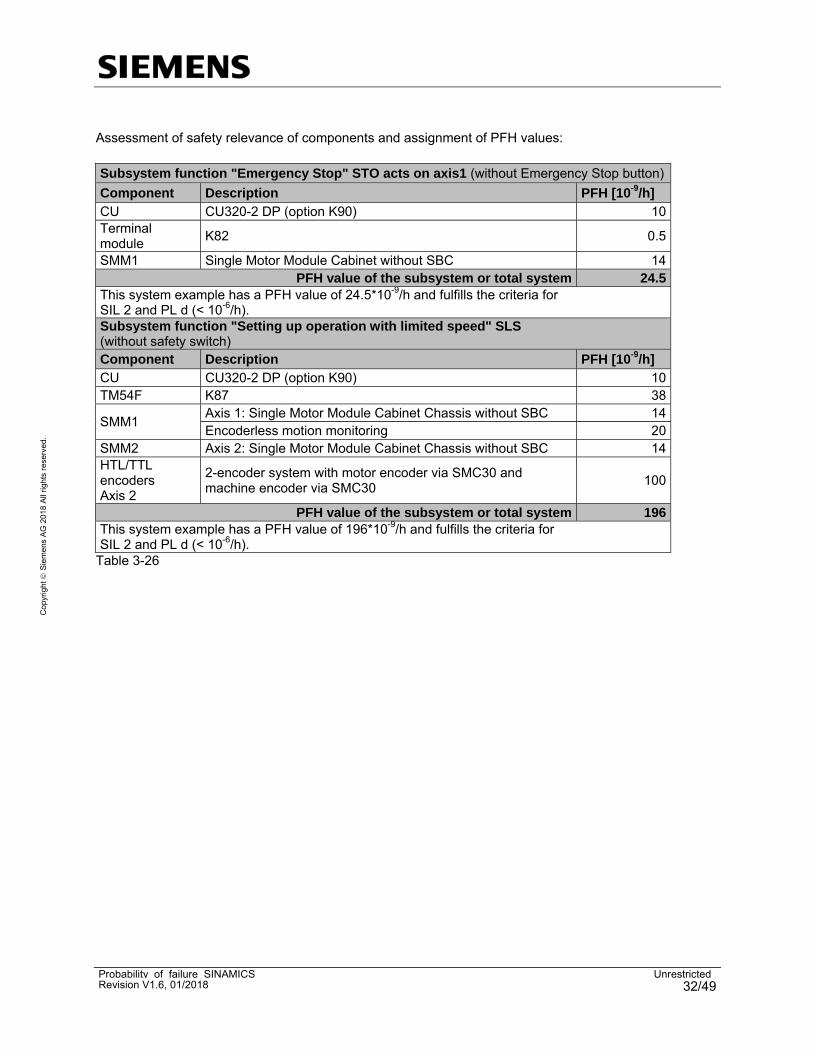
Assessment of safety relevance of components and assignment of PFH values: Subsystem function "Emergency Stop" STO acts on axis1 (without Emergency Stop button)
Component Description PFH [10-9/h] CU CU320-2 DP (option K90) 10Terminal module
K82 0.5
SMM1 Single Motor Module Cabinet without SBC 14PFH value of the subsystem or total system 24.5
This system example has a PFH value of 24.5*10-9/h and fulfills the criteria for SIL 2 and PL d (< 10-6/h). Subsystem function "Setting up operation with limited speed" SLS (without safety switch) Component Description PFH [10-9/h] CU CU320-2 DP (option K90) 10TM54F K87 38
SMM1 Axis 1: Single Motor Module Cabinet Chassis without SBC 14Encoderless motion monitoring 20
SMM2 Axis 2: Single Motor Module Cabinet Chassis without SBC 14HTL/TTL encoders Axis 2
2-encoder system with motor encoder via SMC30 and machine encoder via SMC30
100
PFH value of the subsystem or total system 196This system example has a PFH value of 196*10-9/h and fulfills the criteria for SIL 2 and PL d (< 10-6/h).
Table 3-26

Probability of failure SINAMICS UnrestrictedRevision V1.6, 01/2018 33/49
Cop
yrig
ht
Sie
me
ns A
G 2
018
All
righ
ts r
eser
ved.
3.14 SINAMICS S150
The following values can be used for Basic Functions and Extended Functions.
Product Order number PFH [10-9/h] PFD [10-4] Additional details
Converter
(CU320-2 DP + PM) 6SL3710-7Lxxx-xxx3 24 24 without SBC
Converter
(CU320-2 DP + PM) 6SL3710-7Lxxx-xxx3 25 25 with SBC
Converter
(CU320-2 PN + PM) 6SL3710-7Lxxx-xxx3-Z K95
24 24 without SBC
Converter
(CU320-2 PN + PM) 6SL3710-7Lxxx-xxx3-Z K95
25 25 with SBC
Encoderless motion monitoring without 20 20 --
Encoder evaluation SMC20
for sin/cos encoders
Option K48 26 26 1-encoder system
SMC30 Sensor Modules for HTL/TTL encoders Options K50 and K52 100 100
2-encoder system (value is valid for
both Sensor Modules)
Terminal Module for STO, SS1 Option K821) 0.5 0.5 --
Terminal Module TM54F Option K87 38 38 --
Safe Brake Adapter 230V AC Actuated 1/h
Option K88 2 2 for using SBC
Safe Brake Adapter 230V AC Actuated 1/min
Option K88 120 120 for using SBC
Table 3-27 1) maximum diagnostic test interval = 6 months Note: The Control Unit is included in the values for the S150 converter.

Probability of failure SINAMICS UnrestrictedRevision V1.6, 01/2018 34/49
Cop
yrig
ht
Sie
me
ns A
G 2
018
All
righ
ts r
eser
ved.
Configuration example:
Fig. 3-14 Assessment of safety relevance of components and assignment of PFH values: Subsystem function "Emergency Stop" SS1 time controlled (without Emergency Stop button) Component Description PFH [10-9/h] CU + PM S150 (CU320-2 + Power Module Chassis) without SBC 24Terminal module
Option K82 0.5
PFH value of the subsystem or total system 24.5This system example has a PFH value of 24.5*10-9/h and fulfills the criteria for SIL 2 and PL d (< 10-6/h). Subsystem function "Setting up operation with limited speed" SLS (without safety switch) Component Description PFH [10-9/h] CU + PM S150 (CU320-2 + Power Module Chassis) without SBC 24TM54F Option K87 38Encoder 1-encoder system with Sensor Modules SMC20 26
PFH value of the subsystem or total system 88This system example has a PFH value of 88*10-9/h and fulfills the criteria for SIL 2 and PL d (< 10-6/h).
Table 3-28

Probability of failure SINAMICS UnrestrictedRevision V1.6, 01/2018 35/49
Cop
yrig
ht
Sie
me
ns A
G 2
018
All
righ
ts r
eser
ved.
3.15 SINAMICS S210
The following values can be used for Basic Functions (STO, SS1, SBC).
Product Order number PFH [10-9/h] PFD [10-4]
S210 6SL3210-5HB10-xUFx 50 50
Table 3-29
Configuration example: The e-stop button in this example is connected to the F-DI of the failsafe controller. The activation of STO in the drives is transferred via PROFIsafe.
Figure 3-15 Assessment of safety relevance of components and assignment of PFH values:
Subsystem function "Emergency Stop" STO
Component Description PFH [10-9/h] S7 F-PLC incl. PROFIsafe S7 1500F 3
ET200MP SM526 F-DI 1
E-stop button SIRIUS 3SB3 0,429
Drive 1 S210 50
Drive 2 S210 50
Drive 3 S210 50
Drive 4 S210 50
Drive 5 S210 50
PFH value of the subsystem or total system 254,429This system example has a PFH value of 254,429*10-9/h and fulfills the criteria for SIL 2 and PL d (< 10-6/h).
Table 3-30

Probability of failure SINAMICS UnrestrictedRevision V1.6, 01/2018 36/49
Cop
yrig
ht
Sie
me
ns A
G 2
018
All
righ
ts r
eser
ved.
4 Safety-related parameters for SIMOTICS
4.1 Motors with encoder connection
All of the motors listed here have a DRIVE-CLiQ interface. The subsequently listed PFH values are valid for 1-encoder systems.
Product Order number PFH [10-9/h] Additional details
1FT6 1FT6xxx-xxxxx-xDxx 26 DRIVE-CLiQ
1FT6 1FT6xxx-xxxxx-xLxx 26 DRIVE-CLiQ
1FT6 1FT6xxx-xxxxx-xFxx 26 DRIVE-CLiQ
1FT7 1FT7xxx-xxxxx-xBxx 30 highly integrated DRIVE-CliQ interface (DQI)
1FT7 1FT7xxx-xxxxx-xCxx 30 highly integrated DRIVE-CliQ interface (DQI)
1FT7 1FT7xxx-xxxxx-xDxx 26 integrated DRIVE-CliQ interface (SMI)
1FT7 1FT7xxx-xxxxx-xFxx 26 integrated DRIVE-CliQ interface (SMI)
1FK7 (order number: a = 5; 7) 1FK7xxx-axxxx-xDxx 26 integrated DRIVE-CliQ interface (SMI)
1FK7 (order number: a = 5; 7) 1FK7xxx-axxxx-xFxx 26 integrated DRIVE-CliQ interface (SMI)
1FK7 (order number: a = 5; 7) 1FK7xxx-axxxx-xLxx 26 integrated DRIVE-CliQ interface (SMI)
1FK7 (order number: a = 2; 3; 4) 1FK7xxx-axxxx-xDxx 26 integrated DRIVE-CliQ interface (SMI)
1FK7 (order number: a = 2; 3; 4) 1FK7xxx-axxxx-xFxx 26 integrated DRIVE-CliQ interface (SMI)
1FK7 (order number: a = 2; 3; 4) 1FK7xxx-axxxx-xLxx 26 integrated DRIVE-CliQ interface (SMI)
1FK7 (order number: a = 2; 3; 4) 1FK7xxx-axxxx-xBxx 30 highly integrated DRIVE-CliQ interface (DQI)
1FK7 (order number: a = 2; 3; 4) 1FK7xxx-axxxx-xCxx 30 highly integrated DRIVE-CliQ interface (DQI)
1FK7 (order number: a = 2; 3; 4) 1FK7xxx-axxxx-xQxx 30 highly integrated DRIVE-CliQ interface (DQI)
1FK7 (order number: a = 2; 3; 4) 1FK7xxx-axxxx-xRxx 30 highly integrated DRIVE-CliQ interface (DQI)
1FG1 1FG1xxx-xQxxx-xxxx 30 hochintegrierte DRIVE-CLiQ-Schnittstelle (DQI)
1FG1 1FG1xxx-xRxxx-xxxx 30 hochintegrierte DRIVE-CLiQ-Schnittstelle (DQI)
1FW3 1FW3xxx-xBx6x-xxxx 30 highly integrated DRIVE-CliQ interface (DQI)
1FW3 1FW3xxx-xCx6x-xxxx 30 highly integrated DRIVE-CliQ interface (DQI)
1PH8 1PH8xxx-xDxxx-xxxx 26 DRIVE-CLiQ
1PH8 1PH8xxx-xFxxx-xxxx 26 DRIVE-CLiQ
1PH8 1PH8xxx-xVxxx-xxxx 26 DRIVE-CLiQ
1PH8 1PH8xxx-xUxxx-xxxx 26 DRIVE-CLiQ
1PH7 1PH7xxx-xDxxx-xxxx 26 DRIVE-CLiQ
1PH7 1PH7xxx-xFxxx-xxxx 26 DRIVE-CLiQ
1PH7 1PH7xxx-xQxxx-xxxx 26 DRIVE-CLiQ
1PH7 1PH7xxx-xVxxx-xxxx 26 DRIVE-CLiQ
1PL6 1PL6xxx-xDxxx-xxxx 26 DRIVE-CLiQ
1PL6 1PL6xxx-xFxxx-xxxx 26 DRIVE-CLiQ
1PL6 1PL6xxx-xQxxx-xxxx 26 DRIVE-CLiQ
Table 4-1 More information about useable Siemens motors without DRIVE-CliQ interface and –encoder you will find under: https://support.industry.siemens.com/cs/ww/en/view/33512621

Probability of failure SINAMICS UnrestrictedRevision V1.6, 01/2018 37/49
Cop
yrig
ht
Sie
me
ns A
G 2
018
All
righ
ts r
eser
ved.
For the calculation of the PFHd values of the motor holding brakes the B10d values are used.
Ordernumber Holding brake B10d
1FG1 SH36 to SH80 Standard holding brake option N23 20.000.000
1FG1 SH36 to SH63 Reinforced brake option N24 20.000.000
1FG1 SH80 to SH100 Reinforced brake option N24 16.000.000
1FG1 SH100 Standard holding brake option N23 16.000.000
1FK702x to 1FK708x Standard holding brake 20.000.000
1FK702x to 1FK706x Reinforced brake option N24 20.000.000
1FK708x to 1FK710x Reinforced brake option N24 16.000.000
1FK710x Standard holding brake 16.000.000
1FT703x to 1FT708x Standard holding brake 20.000.000
1FT710x Standard holding brake 16.000.000
1PH808x Mounted holding brake 8.000.000
1PH810x Mounted holding brake 7.000.000
1PH813x Mounted holding brake 6.000.000
1PH816x Mounted holding brake 5.000.000
Table 4-2 Note: The failure rate of the holding brakes depends on the frequency of the operation. According to ISO 13849-1 the constant dangerous failure rate (λd) during this service life is:
with IEC 62061: PFHd = λd * 1h

Probability of failure SINAMICS UnrestrictedRevision V1.6, 01/2018 38/49
Cop
yrig
ht
Sie
me
ns A
G 2
018
All
righ
ts r
eser
ved.
5 Safety-related parameters for SIMOTION
Product Order number PFH [10-9/h]
SIMOTION D410 DP 6AU1410-0AA00-0AA0 10
SIMOTION D410 PN 6AU1410-0AB00-0AA0 10
SIMOTION D410-2 DP 6AU1410-2AA00-0AA0 10
SIMOTION D410-2 DP/PN 6AU1410-2AD00-0AA0 10
SIMOTION D425 6AU1425-0AA00-0AA0 10
SIMOTION D425-2 DP 6AU1425-2AA00-0AA0 10
SIMOTION D425-2 DP/PN 6AU1425-2AD00-0AA0 10
SIMOTION D435 6AU1435-0AA00-0AA0 10
SIMOTION D435 6AU1435-0AA00-0AA1 10
SIMOTION D435-2 DP 6AU1435-2AA00-0AA0 10
SIMOTION D435-2 DP/PN 6AU1435-2AD00-0AA0 10
SIMOTION D445 6AU1445-0AA00-0AA0 10
SIMOTION D445-1 6AU1445-0AA00-0AA1 10
SIMOTION D445-2 DP/PN 6AU1445-2AD00-0AA0 10
SIMOTION D455-2 DP/PN 6AU1455-2AD00-0AA0 10
SIMOTION CX32 6SL3040-0NA00-0AA0 10
SIMOTION CX32-2 6AU1432-2AA00-0AA0 10
Table 5-1 The SINAMICS S120 drive components are listed in Chapter 3.10.

Probability of failure SINAMICS UnrestrictedRevision V1.6, 01/2018 39/49
Cop
yrig
ht
Sie
me
ns A
G 2
018
All
righ
ts r
eser
ved.
Configuration example:
Achse 3Achse 2Achse 1
D445-2
SMM1
M3~
Not-Halt TasterSTO
Motorgeber
DMM2/3
M3~
M3~
SMC20
Motor-geber
Motor-geber
Safety relevant
Nicht Safety relevant
Achse 5Achse 4
DMM4/5
M3~
M3~
SMC20
Motor-geber
Motor-geber
Achse 7
SMM7
M3~
Motor-geber
Achse 8
SMM8
M3~
Motor-geber
PE
Achse 9
SMM9
M3~
Motor-geber
Achse 6
Achse 10
SMM10
M3~
Motor-geber
CX32-2
SMM6
M3~
Motorgeber
ALM
Figure 5-1

Probability of failure SINAMICS UnrestrictedRevision V1.6, 01/2018 40/49
Cop
yrig
ht
Sie
me
ns A
G 2
018
All
righ
ts r
eser
ved.
Assessment of safety relevance of components and assignment of PFH values: Subsystem function "Emergency Stop" STO via Onboard terminals (without Emergency Stop button) Component Description PFH [10-9/h]
CX32-2 SIMOTION Controller Extension 10SMM7 Single Motor Module Booksize without SBC 10SMM8 Single Motor Module Booksize without SBC 10SMM9 Single Motor Module Booksize without SBC 10SMM10 Single Motor Module Booksize without SBC 10
PFH value of the subsystem or total system 50This system example has a PFH value of 50*10-9/h and fulfills the criteria for SIL 2 and PL d (< 10-6/h).
Tabelle 5-2 Subsystem function "Set-up operation with SLS" (Activation via PROFIsafe, without F-CPU and Sensorik) Component Description PFH [10-9/h] D445-2 Control Unit SIMOTION D445-2 10CX32-2 SIMOTION Controller Extension 10DMM2/3 Double Motor Module Booksize, 1x without SBC, 1x with SBC 14Encoder axis 2 Sensor Module Cabinet-Mounted SMC20 26Motor and encoder axis 3
Servomotor with integrated DRIVE-CliQ interface (SMI) 26
SMM6 Single Motor Module Booksize without SBC 10Motor and encoder axis 6
Servomotor with highly integrated DRIVE-CliQ interface (DQI) 30
SMM7 Single Motor Module Booksize without SBC 10Motor and encoder axis 7
Servomotor with highly integrated DRIVE-CliQ interface (DQI) 30
SMM8 Single Motor Module Booksize with SBC 14Motor and encoder axis 8
Servomotor with integrated DRIVE-CliQ interface (SMI) 26
SMM9 Single Motor Module Booksize without SBC 10Motor and encoder axis 9
Servomotor with highly integrated DRIVE-CliQ interface (DQI) 30
SMM10 Single Motor Module Booksize without SBC 10Motor and encoder axis 10
Servomotor with highly integrated DRIVE-CliQ interface (DQI) 30
PFH value of the subsystem or total system 286This system example has a PFH value of 2.86*10-7/h and fulfills the criteria for SIL 2 and PL d (< 10-6/h).
Tabelle 5-3

Probability of failure SINAMICS UnrestrictedRevision V1.6, 01/2018 41/49
Cop
yrig
ht
Sie
me
ns A
G 2
018
All
righ
ts r
eser
ved.
6 Safety-related parameters for SINUMERIK
6.1 SINUMERIK 840D sl
Product Order number PFH [10-9/h] Additional details
NCU 710.1 with PLC 317-2DP 6FC5371-0AA10-0AA0 661) SINUMERIK Safety Integrated
NCU 710.1 with PLC 317-2DP 6FC5371-0AA10-0AA0 10 SINAMICS Safety Integrated Basic Functions
NCU 710.2 with PLC 317-2DP 6FC5371-0AA10-0AA1 661) SINUMERIK Safety Integrated
NCU 710.2 with PLC 317-2DP 6FC5371-0AA10-0AA1 10 SINAMICS Safety Integrated Basic Functions
NCU 710.2 with PLC 317-2DP 6FC5371-0AA10-0AA2 661) SINUMERIK Safety Integrated
NCU 710.2 with PLC 317-2DP 6FC5371-0AA10-0AA2 10 SINAMICS Safety Integrated Basic Functions
NCU 710.3 PN with PLC 317-3PN/DP
6FC5371-0AA30-0AA0 661) SINUMERIK Safety Integrated
NCU 710.3 PN with PLC 317-3PN/DP
6FC5371-0AA30-0AA0 10 SINAMICS Safety Integrated Basic Functions
NCU 710.3 PN with
PLC 317-3PN/DP
6FC5371-0AA30-0AA1 661) SINUMERIK Safety Integrated
NCU 710.3 PN with
PLC 317-3PN/DP
6FC5371-0AA30-0AA1 10 SINAMICS Safety Integrated Basic Functions
NCU 710.3B PN with
PLC 317-3PN/DP
6FC5371-0AA30-0AB0 661) SINUMERIK Safety Integrated
NCU 710.3B PN with
PLC 317-3PN/DP
6FC5371-0AA30-0AB0 10 SINAMICS Safety Integrated Basic Functions
NCU 710.3B PN with
PLC 317-3PN/DP
6FC5371-0AA30-0AB0 141) SINUMERIK Safety Integrated plus
NCU 720.1 with PLC 317-2DP 6FC5372-0AA00-0AA0 661) SINUMERIK Safety Integrated
NCU 720.1 with PLC 317-2DP 6FC5372-0AA00-0AA0 10 SINAMICS Safety Integrated Basic Functions
NCU 720.2 with PLC 317-2DP 6FC5372-0AA00-0AA1 661) SINUMERIK Safety Integrated
NCU 720.2 with PLC 317-2DP 6FC5372-0AA00-0AA1 10 SINAMICS Safety Integrated Basic Functions
NCU 720.2 with PLC 317-2DP 6FC5372-0AA00-0AA2 661) SINUMERIK Safety Integrated
NCU 720.2 with PLC 317-2DP 6FC5372-0AA00-0AA2 10 SINAMICS Safety Integrated Basic Functions
NCU 720.2 PN with
PLC 317-3PN/DP
6FC5372-0AA01-0AA1 661) SINUMERIK Safety Integrated
NCU 720.2 PN with
PLC 317-3PN/DP
6FC5372-0AA01-0AA1 10 SINAMICS Safety Integrated Basic Functions
NCU 720.2 PN with
PLC 317-3PN/DP
6FC5372-0AA01-0AA2 661) SINUMERIK Safety Integrated
NCU 720.2 PN with
PLC 317-3PN/DP
6FC5372-0AA01-0AA2 10 SINAMICS Safety Integrated Basic Functions
NCU 720.3 PN with
PLC 317-3PN/DP
6FC5372-0AA30-0AA0 661) SINUMERIK Safety Integrated
NCU 720.3 PN with
PLC 317-3PN/DP
6FC5372-0AA30-0AA0 10 SINAMICS Safety Integrated Basic Functions
NCU 720.3 PN with PLC 317-3PN/DP
6FC5372-0AA30-0AA1 661) SINUMERIK Safety Integrated

Probability of failure SINAMICS UnrestrictedRevision V1.6, 01/2018 42/49
Cop
yrig
ht
Sie
me
ns A
G 2
018
All
righ
ts r
eser
ved.
NCU 720.3 PN with PLC 317-3PN/DP
6FC5372-0AA30-0AA1 10 SINAMICS Safety Integrated Basic Functions
NCU 720.3B PN with
PLC 317-3PN/DP
6FC5372-0AA30-0AB0 661) SINUMERIK Safety Integrated
NCU 720.3B PN with
PLC 317-3PN/DP
6FC5372-0AA30-0AB0 10 SINAMICS Safety Integrated Basic Functions
NCU 720.3B PN with
PLC 317-3PN/DP
6FC5372-0AA30-0AB0 141) SINUMERIK Safety Integrated plus
NCU 730.1 with PLC 317-2DP 6FC5373-0AA00-0AA0 661) SINUMERIK Safety Integrated
NCU 730.1 with PLC 317-2DP 6FC5373-0AA00-0AA0 10 SINAMICS Safety Integrated Basic Functions
NCU 730.2 with PLC 317-2DP 6FC5373-0AA00-0AA1 661) SINUMERIK Safety Integrated
NCU 730.2 with PLC 317-2DP 6FC5373-0AA00-0AA1 10 SINAMICS Safety Integrated Basic Functions
NCU 730.2 with PLC 317-2DP 6FC5373-0AA00-0AA2 661) SINUMERIK Safety Integrated
NCU 730.2 with PLC 317-2DP 6FC5373-0AA00-0AA2 10 SINAMICS Safety Integrated Basic Functions
NCU 730.2 PN with
PLC 319-3PN/DP
6FC5373-0AA01-0AA1 661) SINUMERIK Safety Integrated
NCU 730.2 PN with
PLC 319-3PN/DP
6FC5373-0AA01-0AA1 10 SINAMICS Safety Integrated Basic Functions
NCU 730.2 PN with PLC 319-3PN/DP
6FC5373-0AA01-0AA2 661) SINUMERIK Safety Integrated
NCU 730.2 PN with PLC 319-3PN/DP
6FC5373-0AA01-0AA2 10 SINAMICS Safety Integrated Basic Functions
NCU 730.3 PN with
PLC 317-3PN/DP
6FC5373-0AA30-0AA0 661) SINUMERIK Safety Integrated
NCU 730.3 PN with PLC 317-3PN/DP
6FC5373-0AA30-0AA0 10 SINAMICS Safety Integrated Basic Functions
NCU 730.3 PN with
PLC 317-3PN/DP
6FC5373-0AA30-0AA1 661) SINUMERIK Safety Integrated
NCU 730.3 PN with
PLC 317-3PN/DP
6FC5373-0AA30-0AA1 10 SINAMICS Safety Integrated Basic Functions
NCU 730.3 PN with
PLC 317-3PN/DP
6FC5373-0AA30-0AB0 661) SINUMERIK Safety Integrated
NCU 730.3 PN with
PLC 317-3PN/DP
6FC5373-0AA30-0AB0 10 SINAMICS Safety Integrated Basic Functions
NCU 730.3B PN with
PLC 317-3PN/DP
6FC5373-0AA31-0AB0 661) SINUMERIK Safety Integrated
NCU 730.3B PN with
PLC 317-3PN/DP
6FC5373-0AA31-0AB0 10 SINAMICS Safety Integrated Basic Functions
NCU 730.3B PN with
PLC 317-3PN/DP
6FC5373-0AA31-0AB0 141) SINUMERIK Safety Integrated plus
NUMERIC CONTROL EXTENSION NX10
6SL3040-0NC00-0AA0 10 --
NUMERIC CONTROL EXTENSION NX15
6SL3040-0NB00-0AA0 10 --
NUMERICAL CONTROL EXTENSION NX10.3
6SL3040-1NC00-0AA0 10 --
NUMERICAL CONTROL EXTENSION NX15.3
6SL3040-1NB00-0AA0 10 --
Table 6-1

Probability of failure SINAMICS UnrestrictedRevision V1.6, 01/2018 43/49
Cop
yrig
ht
Sie
me
ns A
G 2
018
All
righ
ts r
eser
ved.
The SINAMICS S120 drive components are listed in Chapter 3.10. 1) incl. 1 x 10-09 for PROFIsafe Configuration example:
Axis 6Axis 3Axis 2Axis 1
NCU
SMM1
M3~
Emergency Stop buttonSTO
Motor encoder Machine
encoder
ALM1 DMM2/3
M3~
M3~
SMC20SME20
Motor encoder
Motor encoder
SME25
Machine encoder
Safety relevant
Non-Safety relevant
Axis 5Axis 4
DMM4/5
M3~
M3~
SMC20
Motor encoder
Motor encoder
SME25
Machine encoder
SME20
Linear motor3~
Motor encoder
SMM6
Axis 10
SMM10
M3~
Motor encoder
SME25
Machine encoder
Axis 11
SMM11
M3~
Motor encoder
EP
Axis 12
SMM12
M3~
Motor encoder
Axis 13
SMM13
M3~
Motor encoder
Axis 7
SMM7
M3~
Motor encoder
EP
ALM1
Axis 9Axis 8
Machine encoder
DMM8/9
M3~
M3~
SMC20SME20
Motor encoder
Motor encoder
SME20
Machine encoder
NX1 NX2
Figure 6-1

Probability of failure SINAMICS UnrestrictedRevision V1.6, 01/2018 44/49
Cop
yrig
ht
Sie
me
ns A
G 2
018
All
righ
ts r
eser
ved.
Assessment of safety relevance of components and assignment of PFH values: Subsystem function "Emergency Stop" STO (without Emergency Stop button)
Component Description PFH [10-9/h] NCU SINUMERIK Safety Integrated 65NX1 Numeric Control Extension NX10 10
DMM2/3 Axis 2 and axis 3: Double Motor Module Booksize, both axes without SBC
12
Encoder axis 2 2-encoder system with motor encoder via SMC20 and machine encoder via SME20
7
Motor and encoder axis 3
Servomotor 1FT7 (1FT7xxx-xxxxx-xBxx) according to Chapter 4
30
SMM6 Single Motor Module Booksize without SBC 10Encoder axis 6 1-encoder system with motor encoder via SME20 26SMM7 Single Motor Module Booksize without SBC 10
DMM8/9 Axis 8 and axis 9: Double Motor Module Booksize, both axes without SBC
12
Encoder axis 8 2-encoder system with motor encoder via SMC20 and machine encoder via SME20
7
Motor and encoder axis 9
Servomotor 1FT7 (1FT7xxx-xxxxx-xBxx) according to Chapter 4
30
SMM10 Single Motor Module Booksize without SBC 10SMM11 Single Motor Module Booksize without SBC 10
PFH value of the subsystem or total system 239This system example has a PFH value of 239*10-9/h and fulfills the criteria for SIL 2 and PL d (< 10-6/h).
Table 6-2

Probability of failure SINAMICS UnrestrictedRevision V1.6, 01/2018 45/49
Cop
yrig
ht
Sie
me
ns A
G 2
018
All
righ
ts r
eser
ved.
6.2 SINUMERIK 828D
Product Order number PFH [10-9/h]
PPU 240.2 BASIC M 6FC5370-4AM20-0AA0 10
PPU 240.2 BASIC T 6FC5370-4AT20-0AA0 10
PPU 240.3 BASIC vertical 6FC5370-4AA30-0AA0 10
PPU 240.3 BASIC vertical 6FC5370-4AA30-0AA1 10
PPU 241.2 BASIC M 6FC5370-3AM20-0AA0 10
PPU 241.2 BASIC T 6FC5370-3AT20-0AA0 10
PPU 241.3 BASIC horizontal 6FC5370-3AA30-0AA0 10
PPU 241.3 BASIC horizontal 6FC5370-3AA30-0AA1 10
PPU 260.1 6FC5370-6AA00-0AA0 10
PPU 260.2 6FC5370-6AA20-0AA0 10
PPU 260.3 vertical 6FC5370-6AA30-0AA0 10
PPU 260.3 vertikal 6FC5370-6AA30-0AA1 10
PPU 261.1 6FC5370-5AA00-0AA0 10
PPU 261.2 6FC5370-5AA20-0AA0 10
PPU 261.3 horizontal 6FC5370-5AA30-0AA0 10
PPU 261.3 horizontal 6FC5370-5AA30-0AA1 10
PPU 280.1 6FC5370-8AA00-0AA0 10
PPU 280.2 6FC5370-8AA20-0AA0 10
PPU 280.3 vertical 6FC5370-8AA30-0AA0 10
PPU 280.3 vertikal 6FC5370-8AA30-0AA1 10
PPU 281.1 6FC5370-7AA00-0AA0 10
PPU 281.2 6FC5370-7AA20-0AA0 10
PPU 281.3 horizontal 6FC5370-7AA30-0AA0 10
PPU 281.3 horizontal 6FC5370-7AA30-0AA1 10
PPU 290.3 vertikal 6FC5370-8AA30-0BA0 10
NUMERIC CONTROL EXTENSION NX10
6SL3040-0NC00-0AA0 10
NUMERICAL CONTROL EXTENSION NX10.3
6Sl3040-1NC00-0AA0 10
NUMERICAL CONTROL EXTENSION NX15.3
6Sl3040-1NB00-0AA0 10
Table 6-3
The SINAMICS S120 drive components are listed in Chapter 3.10.

Probability of failure SINAMICS UnrestrictedRevision V1.6, 01/2018 46/49
Cop
yrig
ht
Sie
me
ns A
G 2
018
All
righ
ts r
eser
ved.
Configuration example:
Figure 6-2 Assessment of safety relevance of components and assignment of PFH values: Subsystem function "Setting up operation with limited speed" SLS (without safety switch) Component Description PFH [10-9/h]
828D SINUMERIK PPU 10Combi Power Module with 4 integrated power units 44
Encoder axis 1 2-encoder system with DRIVE-CLiQ motor encoder and machine encoder via SMC20
7
Motor and encoder axis 2
Servomotor 1FT7 (1FT7xxx-xxxxx-xBxx) according to Chapter 4
30
Motor and encoder axis 3
Servomotor 1FT7 (1FT7xxx-xxxxx-xBxx) according to Chapter 4
30
Encoder axis 4 2-encoder system with DRIVE-CLiQ motor encoder and machine encoder via SMC20
7
TM54F Terminal Module with F-IO 38PFH value of the subsystem or total system 166
This system example has a PFH value of 166*10-9/h and fulfills the criteria for SIL 2 and PL d (< 10-6/h).
Table 6-4

Probability of failure SINAMICS UnrestrictedRevision V1.6, 01/2018 47/49
Cop
yrig
ht
Sie
me
ns A
G 2
018
All
righ
ts r
eser
ved.
6.3 SINUMERIK 840D with SIMODRIVE 611D
Product Order number PFH [10-9/h]
NCU 561.4 6FC5356-0BB14-0AA0 25
NCU 561.5 6FC5356-0BB15-0AA0 25
NCU 561.5B 6FC5356-0BB15-0AB0 25
NCU 571.4 6FC5357-0BB14-0AA0 25
NCU 571.5 6FC5357-0BB15-0AA0 25
NCU 571.5B 6FC5357-0BB15-0AB0 25
NCU 572.4 6FC5357-0BB24-0AA0 25
NCU 572.5 6FC5357-0BB25-0AA0 25
NCU 572.5B 6FC5357-0BB25-0AB0 25
NCU 573.4 6FC5357-0BB34-0AA0 25
NCU 573.5 6FC5357-0BB35-0AA0 25
NCU 573.5B 6FC5357-0BB35-0AB0 25
1-axis control board
High Performance
6SN1118-0DJ23-0AA0 45
1-axis control board
High Performance
6SN1118-0DJ23-0AA1 45
1-axis control board High Performance
6SN1118-0DJ23-0AA2 45
2-axes control board
High Performance
6SN1118-0DK23-0AA0 60
2-axes control board
High Performance
6SN1118-0DK23-0AA1 60
2-axes control board High Performance
6SN1118-0DK23-0AA2 60
2-axes control board
High Standard
6SN1118-0DM33-0AA0 60
2-axes control board
High Standard
6SN1118-0DM33-0AA1 60
2-axes control board High Standard
6SN1118-0DM33-0AA2 60
Table 6-5
6.4 SINUMERIK handheld units
Product Order number PFH [10-9/h] B10d
HT 2, Emergency Stop command device (with connection box/module PN Basic)
6FC5303-0AA00-2AA0 -- 100.000
HT 2, Emergency Stop command device (with connection box PN Plus)
6FC5303-0AA00-2AA0 101 --
HT 2, enable button 6FC5303-0AA00-2AA0 135 --
HT 8, Emergency Stop command device (with connection box/module PN Basic)
6FC5403-0AA20-0AA0 -- 100.000
HT 8, Emergency Stop command device (with connection box/module PN Basic)
6FC5403-0AA20-1AA0 -- 100.000
HT 8, Emergency Stop command device (with connection box PN Plus)
6FC5403-0AA20-0AA0 101 --
Probability of failure SINAMICS UnrestrictedRevision V1.6, 01/2018 48/49
Cop
yrig
ht
Sie
me
ns A
G 2
018
All
righ
ts r
eser
ved.
HT 8, Emergency Stop command device (with connection box PN Plus)
6FC5403-0AA20-1AA0 101 --
HT 8, enable button 6FC5403-0AA20-0AA0 135 --
HT 8, enable button 6FC5403-0AA20-1AA0 135 --
HT 8, Emergency Stop command device (with connection box/module PN Basic)
6FC5403-0AA20-0AA1 -- 100.000
HT 8, Emergency Stop command device (with connection box/module PN Basic)
6FC5403-0AA20-1AA1 -- 100.000
HT 8, Emergency Stop command device (with connection box PN Plus)
6FC5403-0AA20-0AA1 101 --
HT 8, Emergency Stop command device (with connection box PN Plus)
6FC5403-0AA20-1AA1 101 --
HT 8, enable button 6FC5403-0AA20-0AA1 5,07 --
HT 8, enable button 6FC5403-0AA20-1AA1 5,07 --
Mini handheld unit, Emergency Stop command device
6FX2007-1AD03 -- 100.000
Mini handheld unit, Emergency Stop command device
6FX2007-1AD13 -- 100.000
Mini handheld unit, enable button 6FX2007-1AD03 -- 100.000
Mini handheld unit, enable button 6FX2007-1AD13 -- 100.000
Type B-MPI, Emergency Stop command 6FX2007-1AC04 -- 100.000 Type B-MPI, Emergency Stop command 6FX2007-1AC14 -- 100.000 Type B-MPI, Emergency Stop command 6FX2007-1AE04 -- 100.000 Type B-MPI, Emergency Stop command 6FX2007-1AE14 -- 100.000 Type B-MPI, enable button 6FX2007-1AC04 -- 100.000 Type B-MPI, enable button 6FX2007-1AC14 -- 100.000 Type B-MPI, enable button 6FX2007-1AE04 -- 100.000 Type B-MPI, enable button 6FX2007-1AE14 -- 100.000
Table 6-6
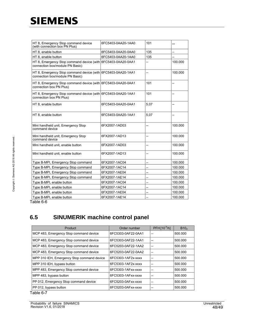
6.5 SINUMERIK machine control panel
Product Order number PFH [10-9/h] B10d
MCP 483, Emergency Stop command device 6FC5303-0AF22-0AA1 -- 500.000
MCP 483, Emergency Stop command device 6FC5303-0AF22-1AA1 -- 500.000 MCP 483, Emergency Stop command device 6FC5203-0AF22-1AA2 -- 500.000
MCP 483, Emergency Stop command device 6FC5203-0AF22-0AA2 -- 500.000
MPP 310 IEH, Emergency Stop command device 6FC5303-1AF2x-xxxx -- 500.000
MPP 310 IEH, bypass button 6FC5303-1AF2x-xxxx -- 500.000 MPP 483, Emergency Stop command device 6FC5303-1AFxx-xxxx -- 500.000
MPP 483, bypass button 6FC5303-1AFxx-xxxx -- 500.000
PP 012, Emergency Stop command device 6FC5203-0AFxx-xxxx -- 500.000 PP 012, bypass button 6FC5203-0AFxx-xxxx -- 500.000
Table 6-7

Probability of failure SINAMICS UnrestrictedRevision V1.6, 01/2018 49/49
Cop
yrig
ht
Sie
me
ns A
G 2
018
All
righ
ts r
eser
ved.
7 Calculation using the Safety Evaluation Tool The configuration examples listed in this document are provided as project for the Safety Evaluation Tool (SET). Open the attached file:
Save the attached file to the local hard disk of your computer Start the "Safety Evaluation Tool" application.
From the pull-down menu and the "Load" program item, load the file into the "Safety Evaluation Tool" application
Figure 7-1
8 Terminology / abbreviations Converter Complete unit with power unit and Control Unit EN European Standard IEC International Electrotechnical Commission ISO International Organization for Standardization Motor Module Inverter, 1-axis or 2-axis version PFD Probability of Failure on Demand PFH Probability of Failure per Hour PL Performance Level PM Power Module (power unit) SIL Safety Integrity Level SLS Safely Limited Speed STO Safe Torque Off
9 History
Version Date Change
V1.0 06/2013 First edition
V1.1 08/2014 Extension of devices
V1.2 02/2015 Extension of devices
V1.2.1 02/2015 Clarification G120
V1.3 04/2016 Extension of devices
V1.4 03/2017 Extension of devices
V1.5 06/2017 Extension of devices
V1.6 01/2018 Extension of devices
Table 9-1