sik binder //217 - linzeecraig.comlinzeecraig.com/ed...
TRANSCRIPT

SIK BINDER //217
6
SIK BINDER //218
CHAPTER 6Tier 1 Difficulty
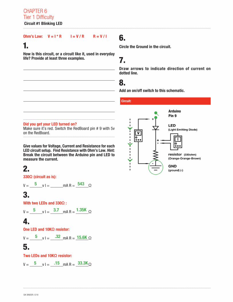
Ohm’s Law: V = I * R I = V / R R = V / I
How is this circuit, or a circuit like it, used in everyday life? Provide at least three examples.
Did you get your LED turned on? Make sure it’s red. Switch the RedBoard pin # 9 with 5v on the RedBoard.
Give values for Voltage, Current and Resistance for each LED circuit setup. Find Resistance with Ohm’s Law. Hint: Break the circuit between the Arduino pin and LED to measure the current.
330Ω (circuit as is): V = ______v I = ______mA R = ______Ω
With two LEDs and 330Ω : V = ______v I = ______mA R = ______Ω
One LED and 10KΩ resistor: V = ______v I = ______mA R = ______Ω
Two LEDs and 10KΩ resistor: V = ______v I = ______mA R = ______Ω
Circle the Ground in the circuit.
Draw arrows to indicate direction of current on dotted line.
Add an on/off switch to this schematic.
Circuit:
Circuit #1 Blinking LED
5 543
1.35K
15.6K
33.3K
3.7
.32
5
5
5 .15
ArduinoPin 9
SIK BINDER //219
What circuits or projects would you like to add LEDs to? List at least three reasons you might add LEDs to an existing circuit or product that you might use. For example: to indicate when a squirt gun is running low on water or to add a flashlight to your hat.
Circuit:
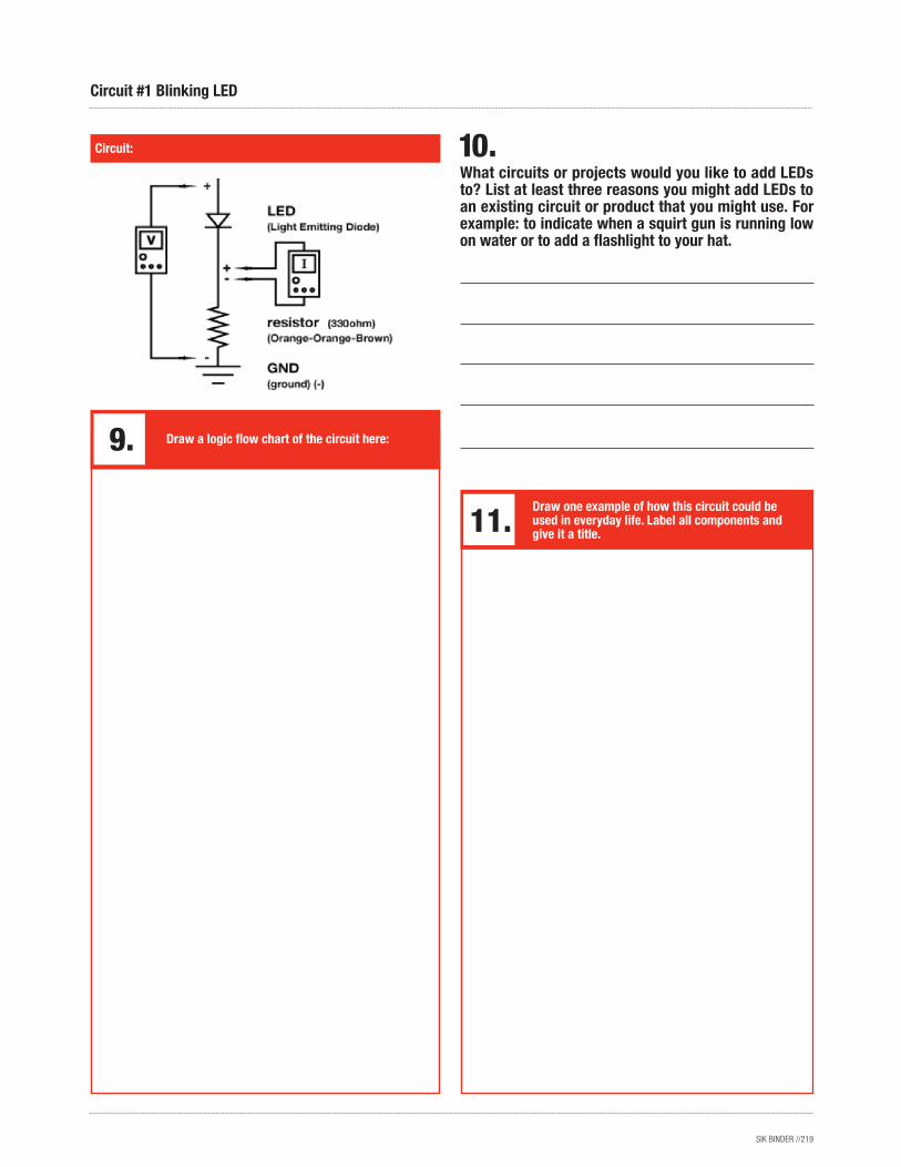
Draw a logic flow chart of the circuit here:
Draw one example of how this circuit could be used in everyday life. Label all components and give it a title.
Circuit #1 Blinking LED
SIK BINDER //220
Circuit:
CHAPTER 6Tier 1 Difficulty Circuit #2 Potentiometers
How is this circuit, or a circuit like it, used in everyday life? Provide at least three examples.
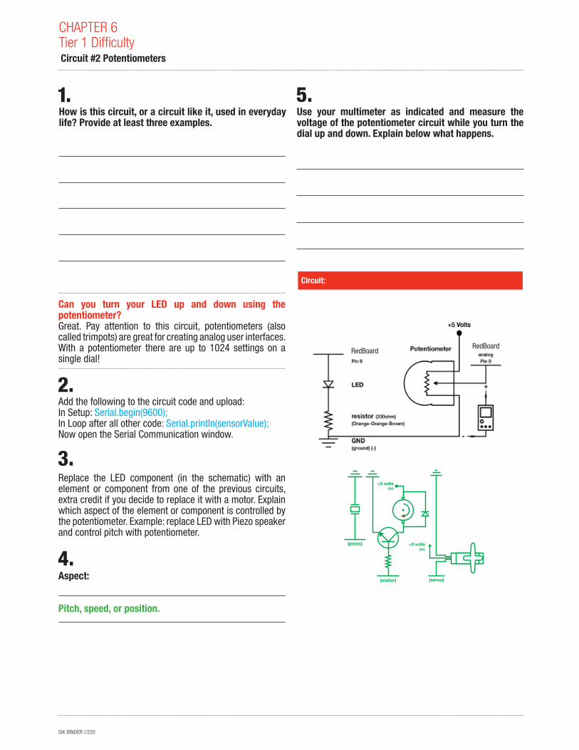
Can you turn your LED up and down using the potentiometer? Great. Pay attention to this circuit, potentiometers (also called trimpots) are great for creating analog user interfaces. With a potentiometer there are up to 1024 settings on a single dial!
Add the following to the circuit code and upload:In Setup: Serial.begin(9600);In Loop after all other code: Serial.println(sensorValue);Now open the Serial Communication window.
Replace the LED component (in the schematic) with an element or component from one of the previous circuits, extra credit if you decide to replace it with a motor. Explain which aspect of the element or component is controlled by the potentiometer. Example: replace LED with Piezo speaker and control pitch with potentiometer.
Aspect:
Use your multimeter as indicated and measure the voltage of the potentiometer circuit while you turn the dial up and down. Explain below what happens.
Pitch, speed, or position.
(servo)
(piezo)
(motor)
+5 volts(5V)
+5 volts(5V)
RedBoardRedBoard
SIK BINDER //221
Circuit:
Circuit #2 Potentiometers
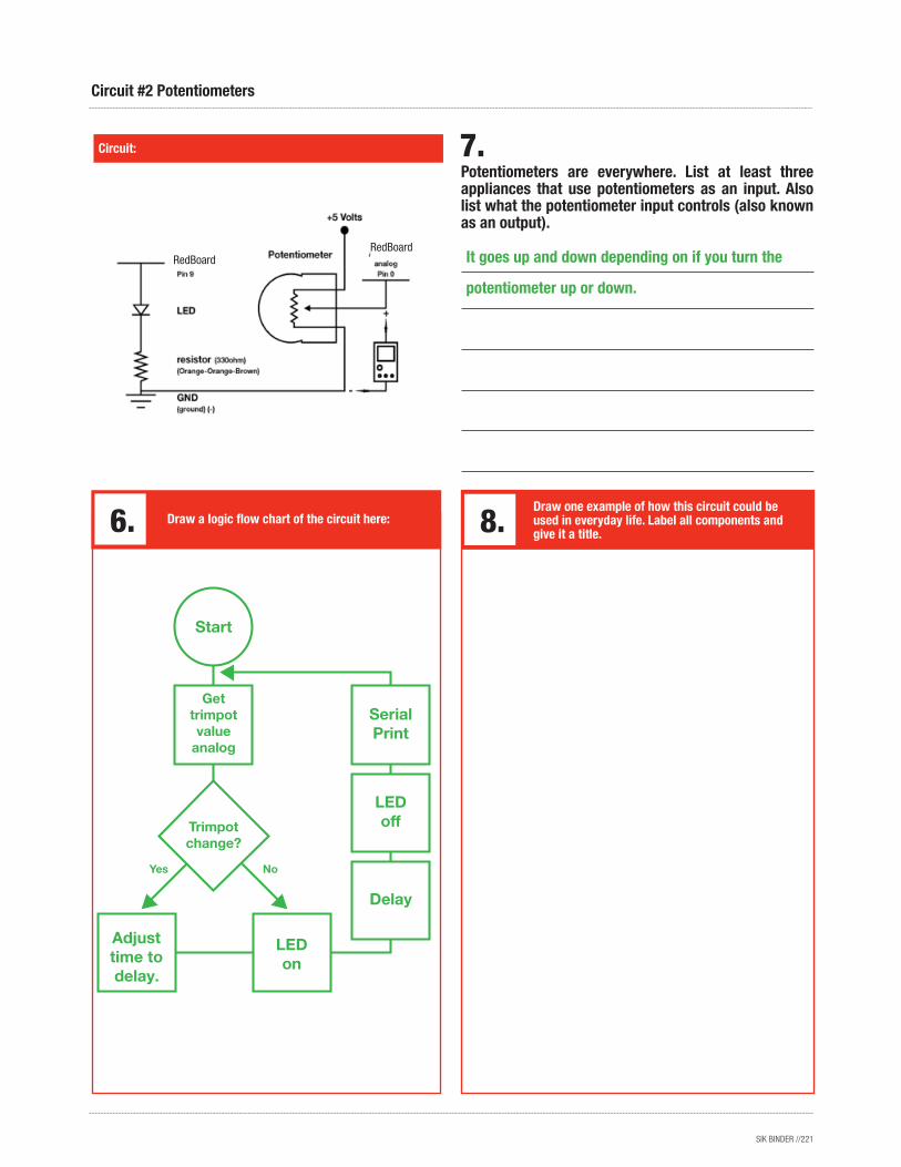
Potentiometers are everywhere. List at least three appliances that use potentiometers as an input. Also list what the potentiometer input controls (also known as an output).
Draw a logic flow chart of the circuit here:Draw one example of how this circuit could be used in everyday life. Label all components and give it a title.
It goes up and down depending on if you turn the
potentiometer up or down.
LED off
Serial Print
Delay
Adjust time to delay.
LED on
Start
Trimpot change?
Get trimpot value
analog
RedBoardRedBoard
SIK BINDER //222
How is this circuit, or a circuit like it, used in everyday life? Provide at least three examples.
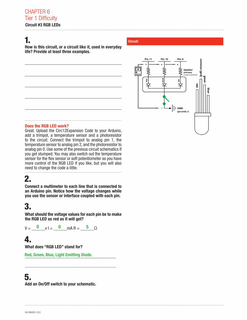
Does the RGB LED work? Great. Upload the Circ12Expansion Code to your Arduino, add a trimpot, a temperature sensor and a photoresistor to the circuit. Connect the trimpot to analog pin 1, the temperature sensor to analog pin 2, and the photoresistor to analog pin 0. Use some of the previous circuit schematics if you get stumped. You may also switch out the temperature sensor for the flex sensor or soft potentiometer so you have more control of the RGB LED if you like, but you will also need to change the code a little.
Connect a multimeter to each line that is connected to an Arduino pin. Notice how the voltage changes while you use the sensor or interface coupled with each pin.
What should the voltage values for each pin be to make the RGB LED as red as it will get?
V = ______v I = ______mA R = ______Ω
What does “RGB LED” stand for?
_________________________________________
_________________________________________
Add an On/Off switch to your schematic.
Circuit:
CHAPTER 6Tier 1 Difficulty Circuit #3 RGB LEDs
Red, Green, Blue, Light Emitting Diode.
50 0
SIK BINDER //223
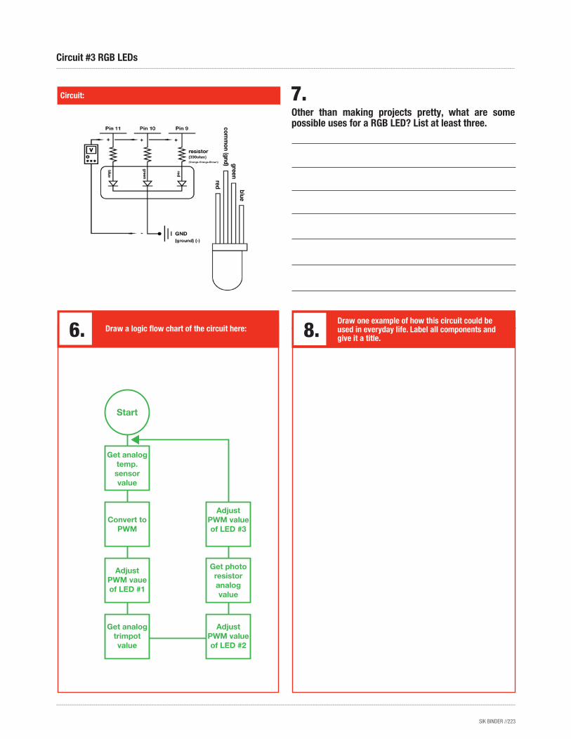
Other than making projects pretty, what are some possible uses for a RGB LED? List at least three.
Circuit:
Circuit #3 RGB LEDs
Draw a logic flow chart of the circuit here:
Get photo resistor analog value
Adjust PWM value of LED #3
Start
Get analog temp. sensor value
Convert to PWM
Adjust PWM vaue of LED #1
Get analog trimpot value
Adjust PWM value of LED #2
Draw one example of how this circuit could be used in everyday life. Label all components and give it a title.
SIK BINDER //224
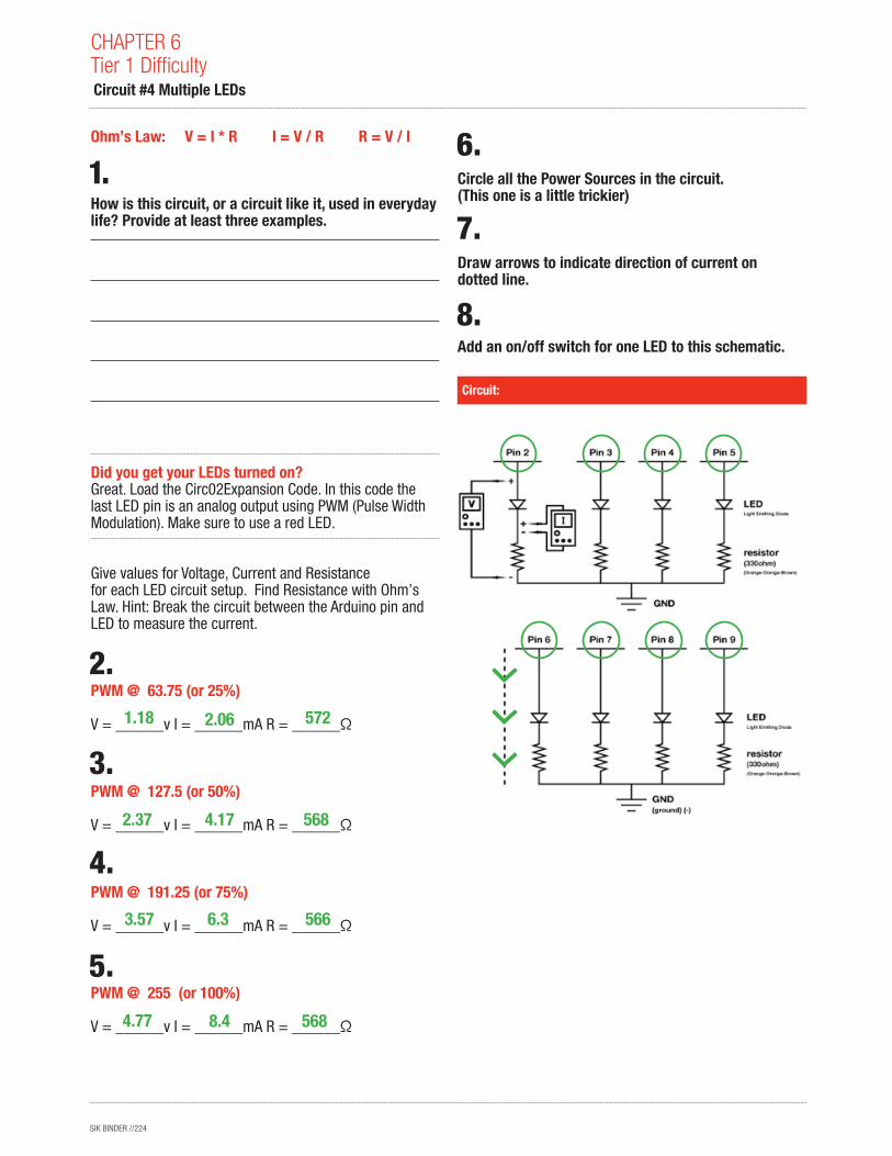
Ohm’s Law: V = I * R I = V / R R = V / I
How is this circuit, or a circuit like it, used in everyday life? Provide at least three examples.
Did you get your LEDs turned on? Great. Load the Circ02Expansion Code. In this code the last LED pin is an analog output using PWM (Pulse Width Modulation). Make sure to use a red LED.
Give values for Voltage, Current and Resistance for each LED circuit setup. Find Resistance with Ohm’s Law. Hint: Break the circuit between the Arduino pin and LED to measure the current.
PWM @ 63.75 (or 25%) V = ______v I = ______mA R = ______Ω
PWM @ 127.5 (or 50%) V = ______v I = ______mA R = ______Ω
PWM @ 191.25 (or 75%) V = ______v I = ______mA R = ______Ω
PWM @ 255 (or 100%) V = ______v I = ______mA R = ______Ω
Circle all the Power Sources in the circuit. (This one is a little trickier)
Draw arrows to indicate direction of current on dotted line.
Add an on/off switch for one LED to this schematic.
Circuit:
CHAPTER 6Tier 1 Difficulty Circuit #4 Multiple LEDs
568
566
568
572
4.77
3.57
2.37
1.18
8.4
6.3
4.17
2.06
SIK BINDER //225
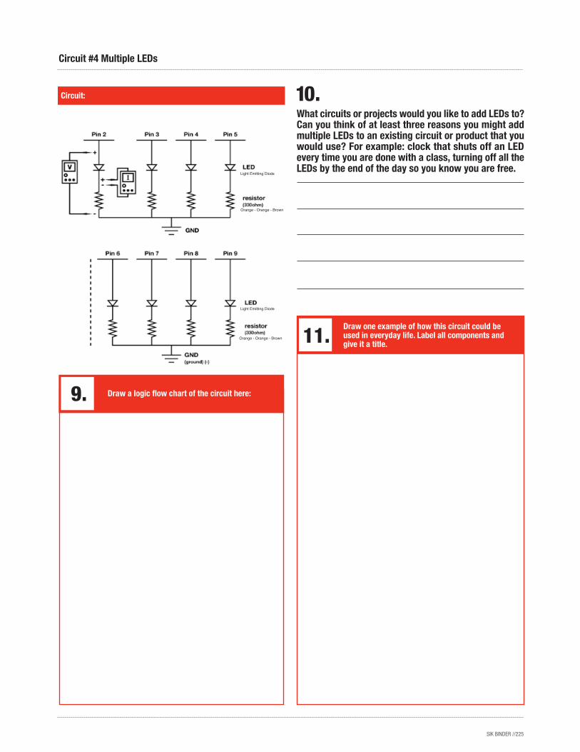
What circuits or projects would you like to add LEDs to? Can you think of at least three reasons you might add multiple LEDs to an existing circuit or product that you would use? For example: clock that shuts off an LED every time you are done with a class, turning off all the LEDs by the end of the day so you know you are free.
Circuit:
Circuit #4 Multiple LEDs
Draw a logic flow chart of the circuit here:
Draw one example of how this circuit could be used in everyday life. Label all components and give it a title.
Light Emitting Diode
Light Emitting Diode
Orange - Orange - Brown
Orange - Orange - Brown
SIK BINDER //226
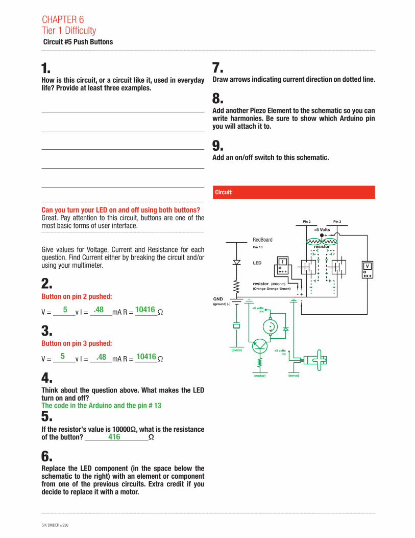
Give values for Voltage, Current and Resistance for each question. Find Current either by breaking the circuit and/or using your multimeter.
Button on pin 2 pushed: V = ______v I = ______mA R = ______Ω
Button on pin 3 pushed:
V = ______v I = ______mA R = ______Ω
Think about the question above. What makes the LED turn on and off?
If the resistor’s value is 10000Ω, what is the resistance of the button? _________________Ω
Replace the LED component (in the space below the schematic to the right) with an element or component from one of the previous circuits. Extra credit if you decide to replace it with a motor.
Circuit:
CHAPTER 6Tier 1 Difficulty Circuit #5 Push Buttons
How is this circuit, or a circuit like it, used in everyday life? Provide at least three examples.
Can you turn your LED on and off using both buttons? Great. Pay attention to this circuit, buttons are one of the most basic forms of user interface.
Draw arrows indicating current direction on dotted line.
Add another Piezo Element to the schematic so you can write harmonies. Be sure to show which Arduino pin you will attach it to.
Add an on/off switch to this schematic.
10416
10416
416
The code in the Arduino and the pin # 13
5
5
.48
.48
Arduino Pin 13
Pin 2
+5 Volts
resistor
Pin 3
LED
resistor(Orange-Orange-Brown)
GND(ground) (-)
(piezo)
(motor) (servo)
(330ohm)
+
-+5 volts
(5V)
+5 volts(5V)
RedBoard
SIK BINDER //227
Circuit:
Circuit #5 Push Buttons
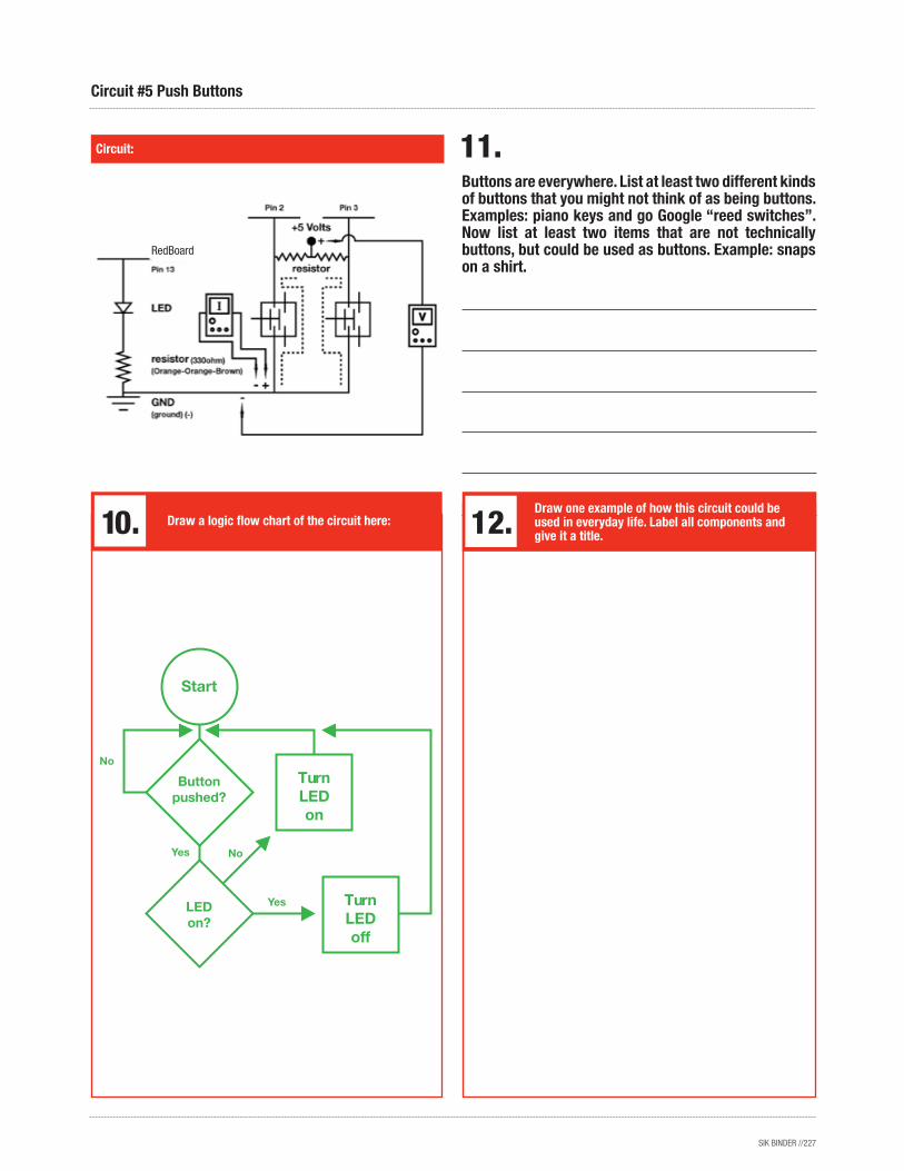
Buttons are everywhere. List at least two different kinds of buttons that you might not think of as being buttons. Examples: piano keys and go Google “reed switches”. Now list at least two items that are not technically buttons, but could be used as buttons. Example: snaps on a shirt.
Draw a logic flow chart of the circuit here:Draw one example of how this circuit could be used in everyday life. Label all components and give it a title.
Turn LED on
Turn LED off
Start
Button pushed?
LEDon?
RedBoard
SIK BINDER //228
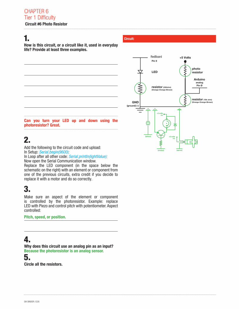
Can you turn your LED up and down using the photoresistor? Great.
Add the following to the circuit code and upload:In Setup: Serial.begin(9600);In Loop after all other code: Serial.println(lightValue);Now open the Serial Communication window.Replace the LED component (in the space below the schematic on the right) with an element or component from one of the previous circuits, extra credit if you decide to replace it with a motor and do so correctly.
Make sure an aspect of the element or component is controlled by the photoresistor. Example: replace LED with Piezo and control pitch with potentiometer. Aspect controlled:
Why does this circuit use an analog pin as an input?
Circle all the resistors.
Circuit:
CHAPTER 6Tier 1 Difficulty Circuit #6 Photo Resistor
How is this circuit, or a circuit like it, used in everyday life? Provide at least three examples.
Arduino Pin 9
Arduino
Pin Øanalog
LED
GND(ground) (-)
+5 Volts
resistor(Orange-Orange-Brown)
(330ohm)
photoresistor
resistor(Orange-Orange-Brown)
(10k ohm)
(servo)
(piezo)
(motor)
+5 volts(5V)
+5 volts(5V)
Because the photoresistor is an analog sensor.
Pitch, speed, or position.
RedBoard
SIK BINDER //229
Circuit:
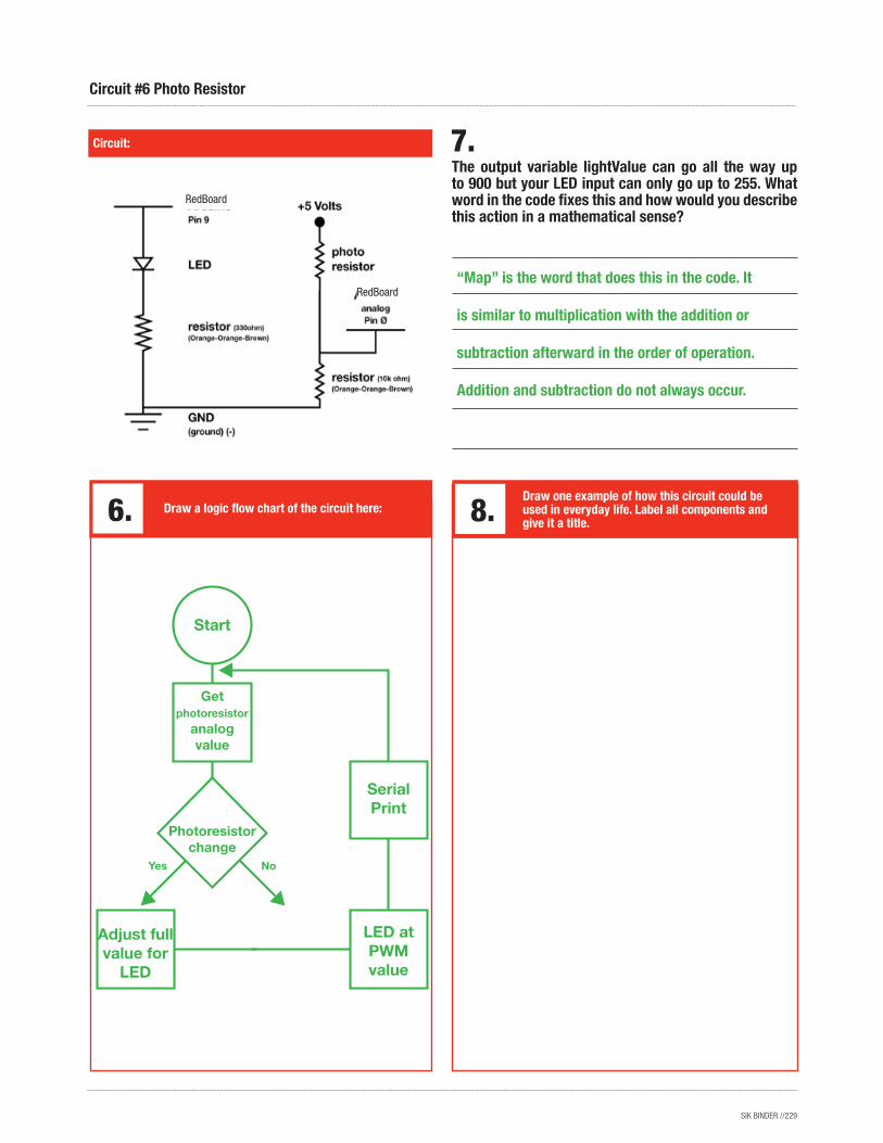
Circuit #6 Photo Resistor
The output variable lightValue can go all the way up to 900 but your LED input can only go up to 255. What word in the code fixes this and how would you describe this action in a mathematical sense?
Draw a logic flow chart of the circuit here:Draw one example of how this circuit could be used in everyday life. Label all components and give it a title.
Serial Print
LED at PWM value
Adjust full value for
LED
Start
Photoresistor change
Get photoresistor
analog value
“Map” is the word that does this in the code. It
is similar to multiplication with the addition or
subtraction afterward in the order of operation.
Addition and subtraction do not always occur.
RedBoard
RedBoard
SIK BINDER //230
Circuit:
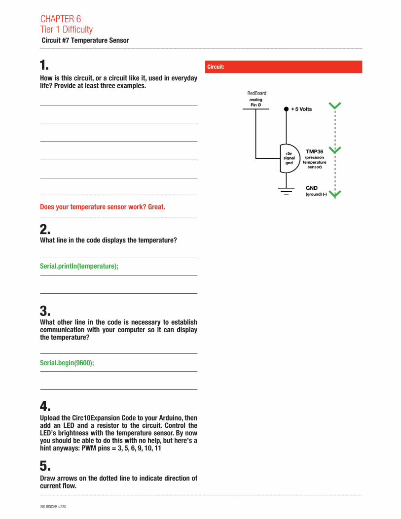
CHAPTER 6Tier 1 Difficulty Circuit #7 Temperature Sensor
How is this circuit, or a circuit like it, used in everyday life? Provide at least three examples.
Does your temperature sensor work? Great.
What line in the code displays the temperature?
What other line in the code is necessary to establish communication with your computer so it can display the temperature?
Upload the Circ10Expansion Code to your Arduino, then add an LED and a resistor to the circuit. Control the LED’s brightness with the temperature sensor. By now you should be able to do this with no help, but here’s a hint anyways: PWM pins = 3, 5, 6, 9, 10, 11
Draw arrows on the dotted line to indicate direction of current flow.
Serial.println(temperature);
Serial.begin(9600);
RedBoard
SIK BINDER //231
What ways, other than controlling an air conditioner, could a temperature sensor be useful? List at least three and explain what is controlled by the temperature sensor in each.
Circuit:
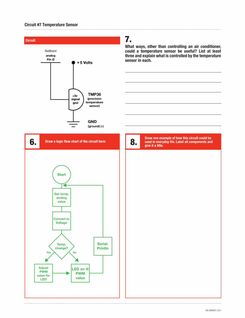
Circuit #7 Temperature Sensor
Draw a logic flow chart of the circuit here:Draw one example of how this circuit could be used in everyday life. Label all components and give it a title.
Serial. Println
LED on @ PWM value
Adjust PWM
value for LED
Start
Temp. change?
Get temp. analog value
Convert to Voltage
RedBoard
SIK BINDER //232
Ohm’s Law: V = I * R I = V / R R = V / I
How is this circuit, or a circuit like it, used in everyday life? Provide at least three examples.
Do you have your servo running? Great.
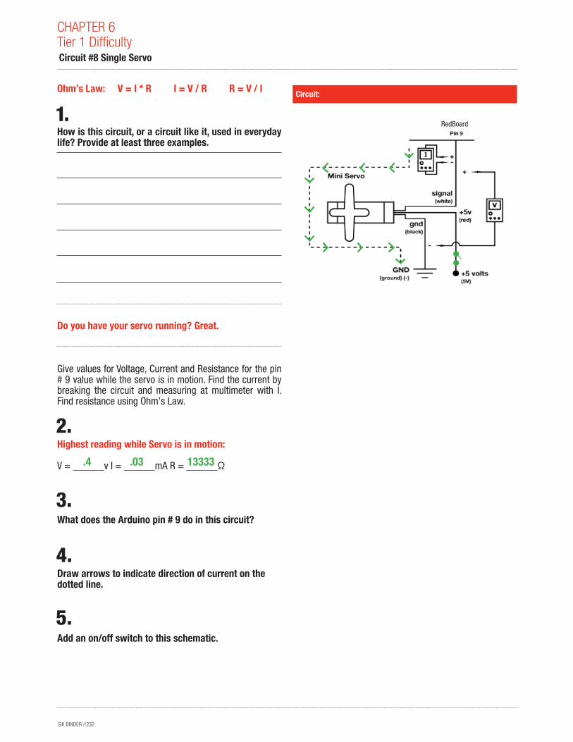
Give values for Voltage, Current and Resistance for the pin # 9 value while the servo is in motion. Find the current by breaking the circuit and measuring at multimeter with I. Find resistance using Ohm’s Law.
Highest reading while Servo is in motion: V = ______v I = ______mA R = ______Ω
What does the Arduino pin # 9 do in this circuit?
Draw arrows to indicate direction of current on the dotted line.
Add an on/off switch to this schematic.
Circuit:
CHAPTER 6Tier 1 Difficulty Circuit #8 Single Servo
13333.4 .03
RedBoard
SIK BINDER //233
A Servo can’t rotate continuously more than 360 degrees, as opposed to a motor which can turn all the way past 360 degrees as many times as you like. However, a servo remembers what its position is while a motor only knows if it is running forward or backwards. Can you think of any situations in which you would need a Servo instead of a motor? How about the other way around? Write three examples, at least one of each, below.
Circuit:
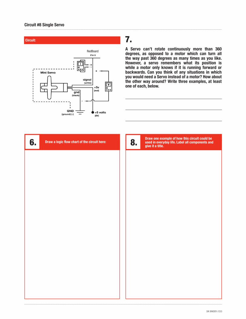
Circuit #8 Single Servo
Draw a logic flow chart of the circuit here:Draw one example of how this circuit could be used in everyday life. Label all components and give it a title.
RedBoard
SIK BINDER //234
Now we’re starting to work with some more complicated sensors. The flex sensor has tons of real world applications. List three and explain why you can’t use a regular potentiometer instead of a flex sensor. Example: use the sensor to measure the flex on a fishing pole and cut the line if the pole ever comes close to breaking. You could not use a potentiometer because it would be difficult to attach it.
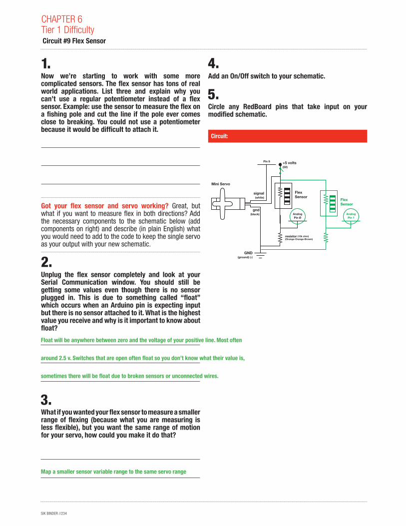
Got your flex sensor and servo working? Great, but what if you want to measure flex in both directions? Add the necessary components to the schematic below (add components on right) and describe (in plain English) what you would need to add to the code to keep the single servo as your output with your new schematic.
Unplug the flex sensor completely and look at your Serial Communication window. You should still be getting some values even though there is no sensor plugged in. This is due to something called “float” which occurs when an Arduino pin is expecting input but there is no sensor attached to it. What is the highest value you receive and why is it important to know about float?
What if you wanted your flex sensor to measure a smaller range of flexing (because what you are measuring is less flexible), but you want the same range of motion for your servo, how could you make it do that?
Circuit:
CHAPTER 6Tier 1 Difficulty Circuit #9 Flex Sensor
1.
2.
Add an On/Off switch to your schematic.
Circle any RedBoard pins that take input on your modified schematic.
resistor(Orange-Orange-Brown)
(10k ohm)
Mini Servo
FlexSensor
Pin 9
Pin ØAnalog
+5 volts(5V)
GND(ground) (-)
gnd(black)
signal(white)
Pin 1Analog
FlexSensor
Float will be anywhere between zero and the voltage of your positive line. Most often
around 2.5 v. Switches that are open often float so you don’t know what their value is,
sometimes there will be float due to broken sensors or unconnected wires.
Map a smaller sensor variable range to the same servo range
SIK BINDER //235
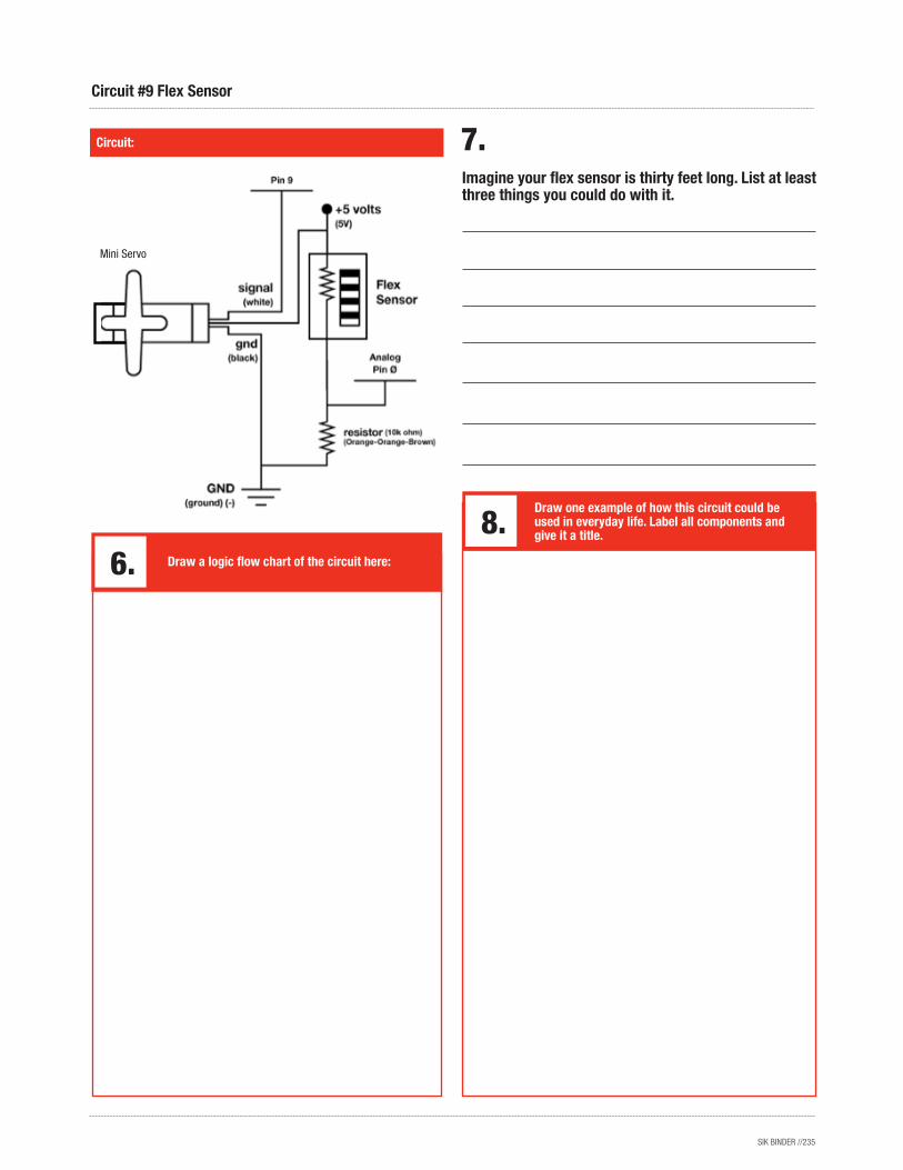
Imagine your flex sensor is thirty feet long. List at least three things you could do with it.
Circuit:
Circuit #9 Flex Sensor
Draw a logic flow chart of the circuit here:
Draw one example of how this circuit could be used in everyday life. Label all components and give it a title.
Mini Servo
SIK BINDER //236
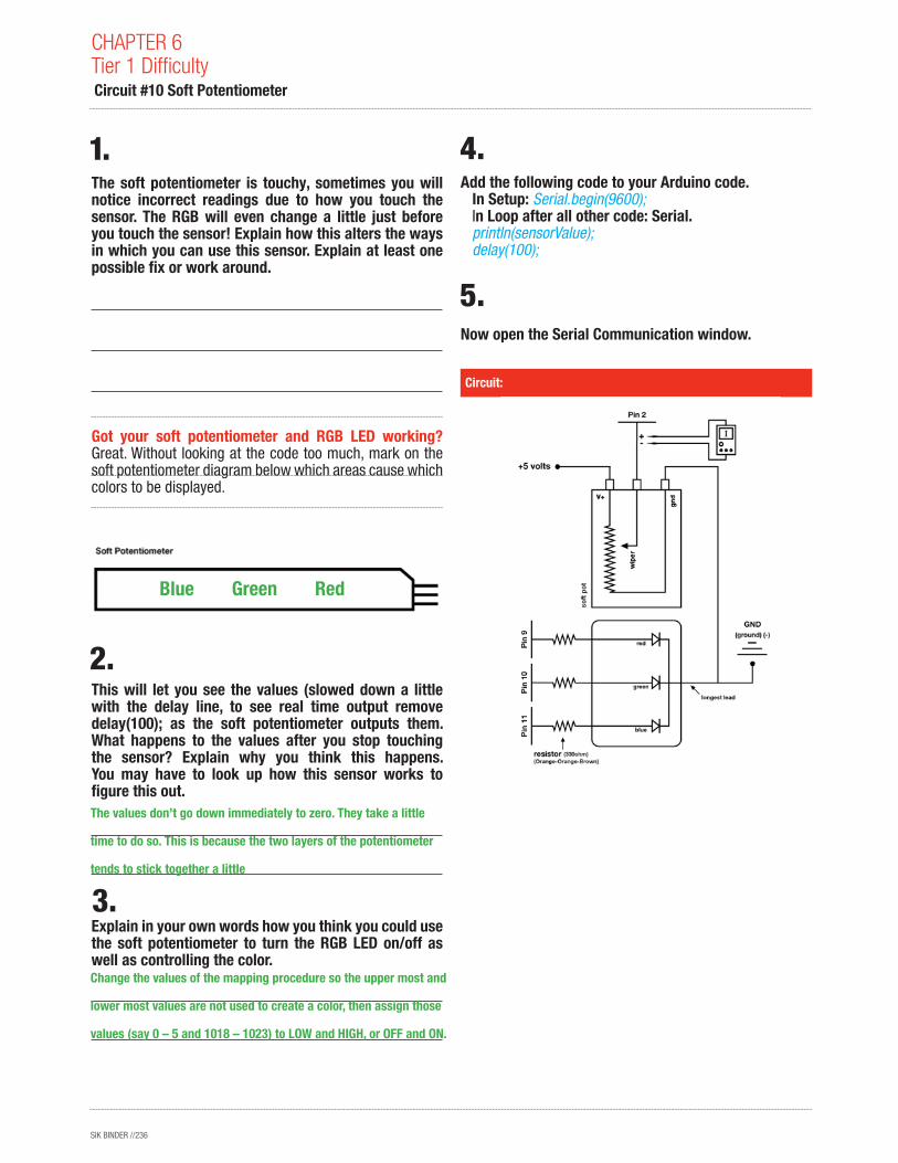
The soft potentiometer is touchy, sometimes you will notice incorrect readings due to how you touch the sensor. The RGB will even change a little just before you touch the sensor! Explain how this alters the ways in which you can use this sensor. Explain at least one possible fix or work around.
Got your soft potentiometer and RGB LED working? Great. Without looking at the code too much, mark on the soft potentiometer diagram below which areas cause which colors to be displayed.
This will let you see the values (slowed down a little with the delay line, to see real time output remove delay(100); as the soft potentiometer outputs them. What happens to the values after you stop touching the sensor? Explain why you think this happens. You may have to look up how this sensor works to figure this out.
Explain in your own words how you think you could use the soft potentiometer to turn the RGB LED on/off as well as controlling the color.
Add the following code to your Arduino code. In Setup: Serial.begin(9600); In Loop after all other code: Serial. println(sensorValue); delay(100);
Now open the Serial Communication window.
Circuit:
CHAPTER 6Tier 1 Difficulty Circuit #10 Soft Potentiometer
The values don’t go down immediately to zero. They take a little
time to do so. This is because the two layers of the potentiometer
tends to stick together a little
Change the values of the mapping procedure so the upper most and
lower most values are not used to create a color, then assign those
values (say 0 – 5 and 1018 – 1023) to LOW and HIGH, or OFF and ON.
Blue Green Red
SIK BINDER //237
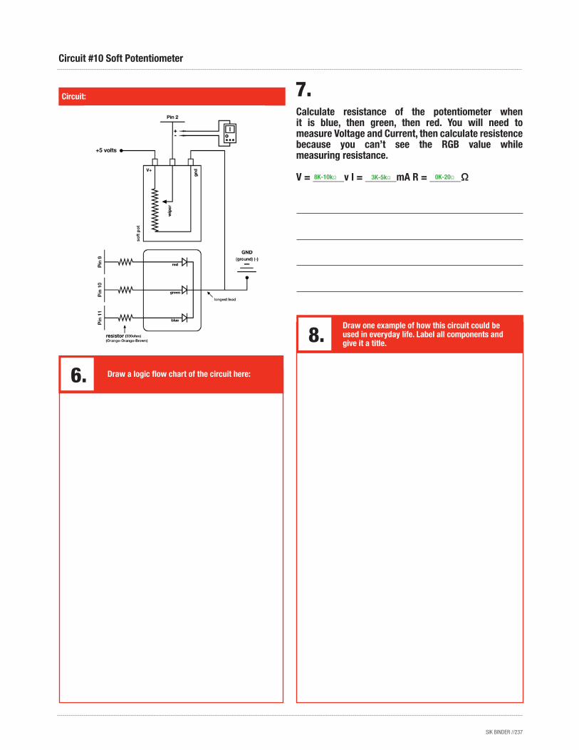
Calculate resistance of the potentiometer when it is blue, then green, then red. You will need to measure Voltage and Current, then calculate resistence because you can’t see the RGB value while measuring resistance.
V = ______v I = ______mA R = ______Ω
Circuit:
Circuit #10 Soft Potentiometer
Draw a logic flow chart of the circuit here:
Draw one example of how this circuit could be used in everyday life. Label all components and give it a title.
8K-10kΩ 3K-5kΩ 0K-20Ω

SIK BINDER //238
Ohm’s Law: V = I * R I = V / R R = V / I
How is this circuit, or a circuit like it, used in everyday life? Provide at least three examples.
Do you have the annoying song blaring out of your speaker? Upload Circ06Expansion Code to your RedBoard.
Give values for Voltage, Current and Resistance for each note value. Find Current by breaking the circuit and using your multimeter. Record voltage to the thousandths place. Calculate Resistance using Ohm’s Law.
Note A: V = ______v I = ______mA R = ______Ω
Note C:
V = ______v I = ______mA R = ______Ω
Note E:
V = ______v I = ______mA R = ______Ω
Note G:
V = ______v I = ______mA R = ______Ω
What does the Arduino pin # 9 do in this circuit?
Draw arrows indicating current direction on dotted line.
Add another Piezo Element to the schematic so you can write harmonies. Be sure to show which Arduino pin you will attach it to.
Add an on/off switch to this schematic.
Circuit:
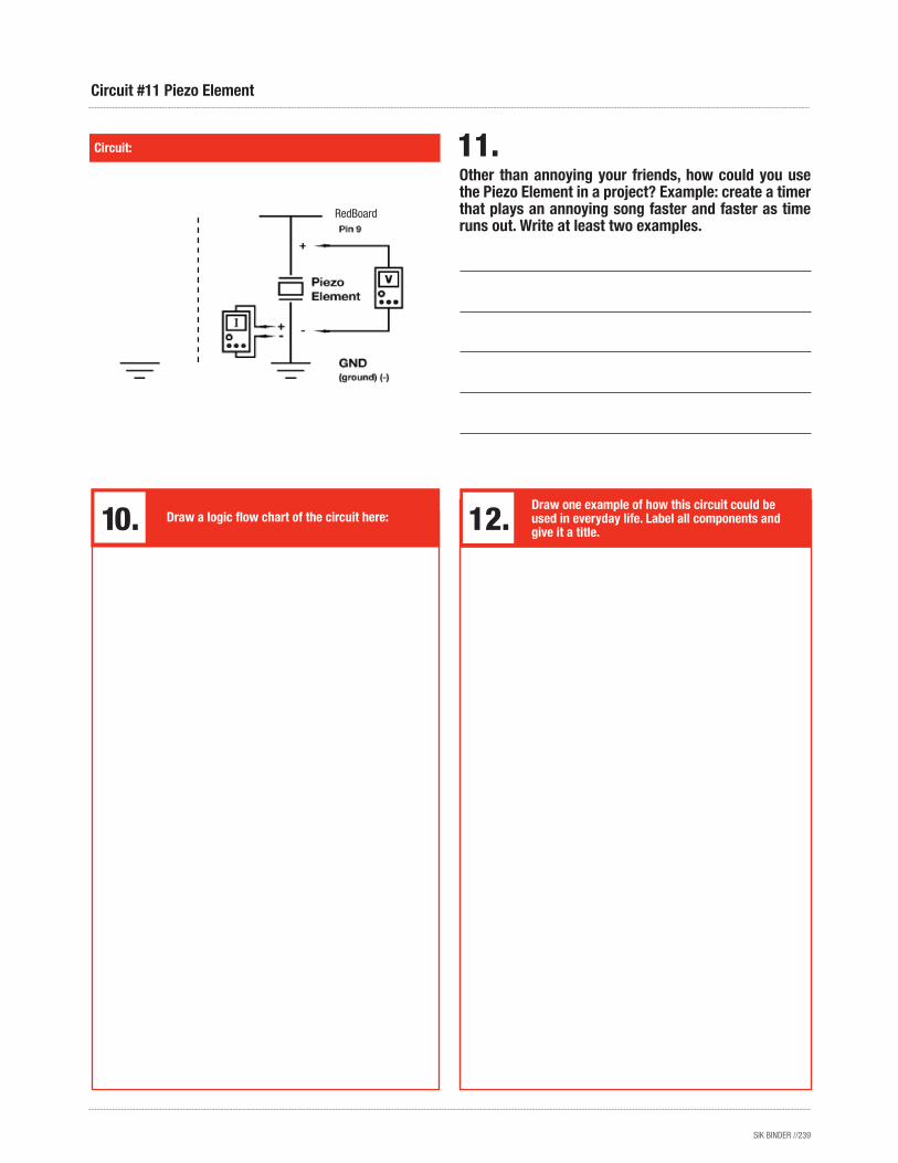
CHAPTER 6Tier 1 Difficulty Circuit #11 Piezo Element
18
18
18
18
.689
.681
.684
.686
39.2
38.7
38.8
39.1
ArduinoPin 3, 5, 6, 10, or 11
RedBoard
RedBoard
SIK BINDER //239
Other than annoying your friends, how could you use the Piezo Element in a project? Example: create a timer that plays an annoying song faster and faster as time runs out. Write at least two examples.
Circuit:
Circuit #11 Piezo Element
Draw a logic flow chart of the circuit here:Draw one example of how this circuit could be used in everyday life. Label all components and give it a title.
RedBoard
SIK BINDER //240
Ohm’s Law: V = I * R I = V / R R = V / I
How is this circuit, or a circuit like it, used in everyday life? Provide at least three examples.
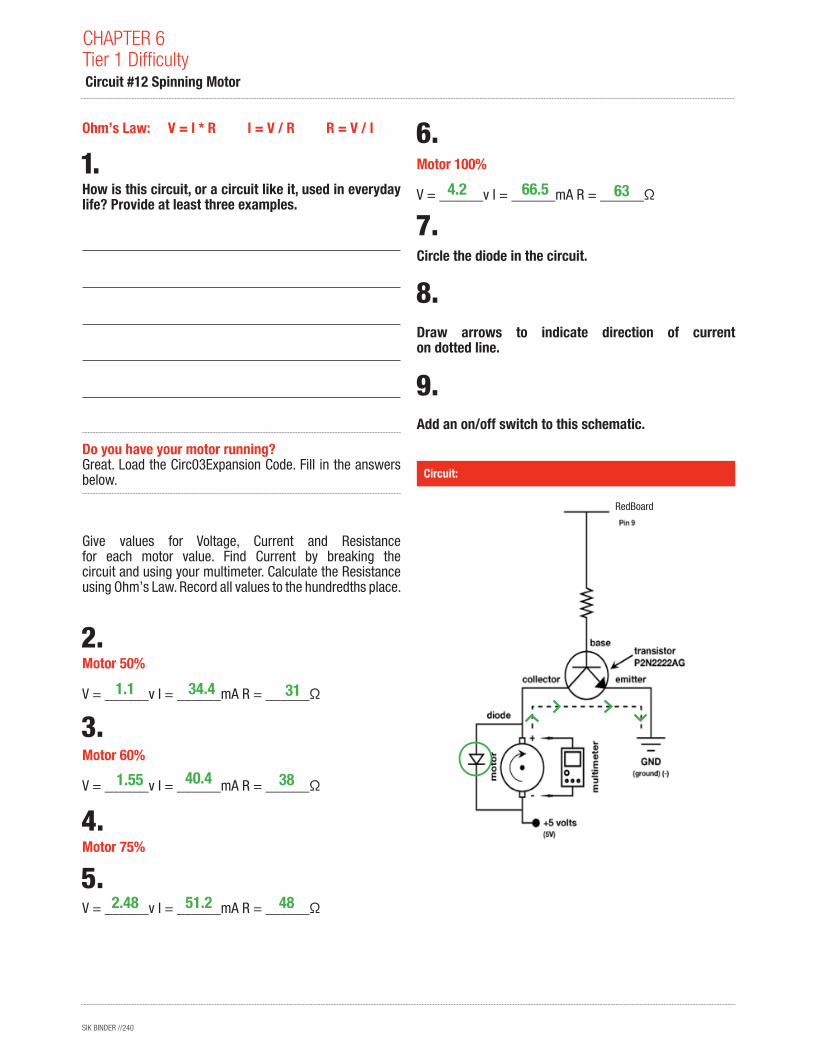
Do you have your motor running? Great. Load the Circ03Expansion Code. Fill in the answers below.
Give values for Voltage, Current and Resistance for each motor value. Find Current by breaking the circuit and using your multimeter. Calculate the Resistance using Ohm’s Law. Record all values to the hundredths place.
Motor 50% V = ______v I = ______mA R = ______Ω
Motor 60% V = ______v I = ______mA R = ______Ω
Motor 75%
V = ______v I = ______mA R = ______Ω
Motor 100% V = ______v I = ______mA R = ______Ω
Circle the diode in the circuit.
Draw arrows to indicate direction of current on dotted line.
Add an on/off switch to this schematic.
Circuit:
CHAPTER 6Tier 1 Difficulty Circuit #12 Spinning Motor
31
38
48
63
1.1
1.55
2.48
4.2
34.4
40.4
51.2
66.5
RedBoard
SIK BINDER //241
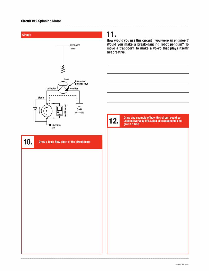
How would you use this circuit if you were an engineer? Would you make a break-dancing robot penguin? To move a trapdoor? To make a yo-yo that plays itself? Get creative.
Circuit:
Circuit #12 Spinning Motor
Draw a logic flow chart of the circuit here:
Draw one example of how this circuit could be used in everyday life. Label all components and give it a title.
RedBoard
SIK BINDER //242
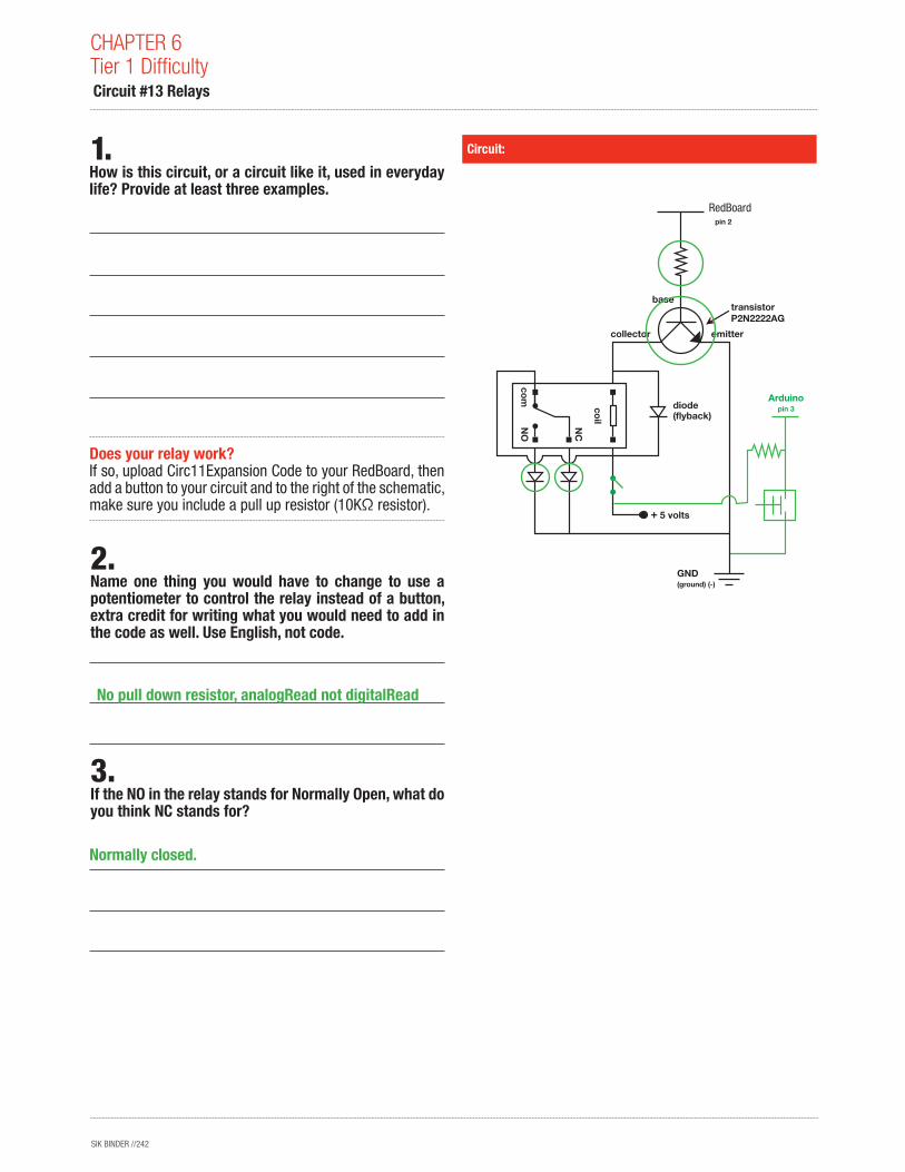
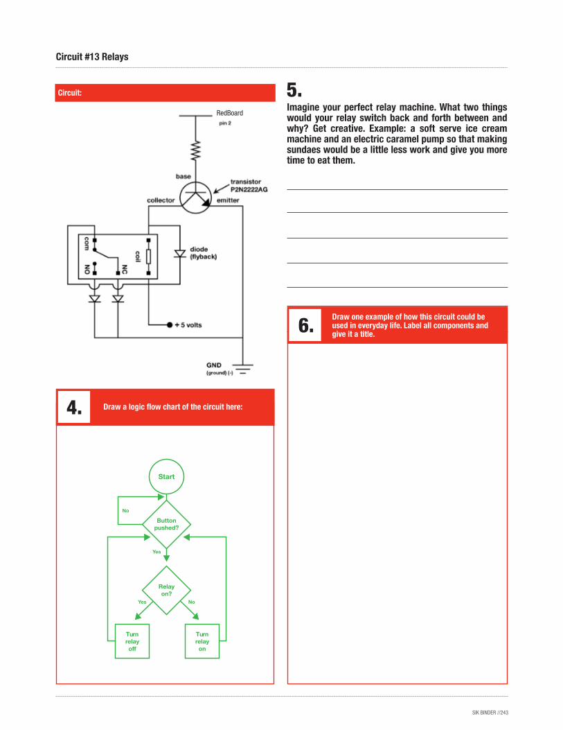
CHAPTER 6Tier 1 Difficulty Circuit #13 Relays
Circuit:
How is this circuit, or a circuit like it, used in everyday life? Provide at least three examples.
Does your relay work? If so, upload Circ11Expansion Code to your RedBoard, then add a button to your circuit and to the right of the schematic, make sure you include a pull up resistor (10KΩ resistor).
Name one thing you would have to change to use a potentiometer to control the relay instead of a button, extra credit for writing what you would need to add in the code as well. Use English, not code.
If the NO in the relay stands for Normally Open, what do you think NC stands for?
1.
3.
2.GND(ground) (-)
basetransistor P2N2222AG
collector
diode(flyback)
coilNC
NO
com
emitter
Arduino pin 2
Arduino pin 3
5 volts
No pull down resistor, analogRead not digitalRead
Normally closed.
RedBoard
SIK BINDER //243
Circuit #13 Relays
Imagine your perfect relay machine. What two things would your relay switch back and forth between and why? Get creative. Example: a soft serve ice cream machine and an electric caramel pump so that making sundaes would be a little less work and give you more time to eat them.
Circuit:
Draw a logic flow chart of the circuit here:
Draw one example of how this circuit could be used in everyday life. Label all components and give it a title.
Turn relay on
Turn relay off
Start
Relayon?
Button pushed?
RedBoard
SIK BINDER //244
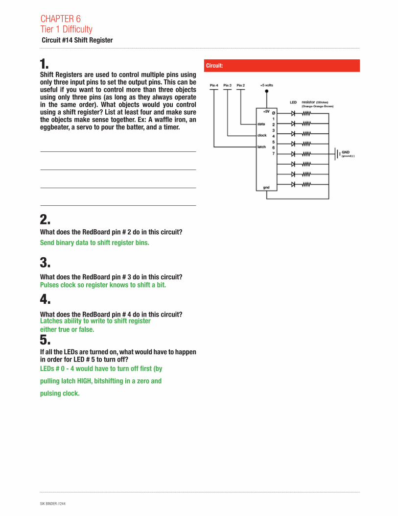
Shift Registers are used to control multiple pins using only three input pins to set the output pins. This can be useful if you want to control more than three objects using only three pins (as long as they always operate in the same order). What objects would you control using a shift register? List at least four and make sure the objects make sense together. Ex: A waffle iron, an eggbeater, a servo to pour the batter, and a timer.
What does the RedBoard pin # 2 do in this circuit?
What does the RedBoard pin # 3 do in this circuit?
What does the RedBoard pin # 4 do in this circuit?
If all the LEDs are turned on, what would have to happen in order for LED # 5 to turn off?
Circuit:
CHAPTER 6Tier 1 Difficulty Circuit #14 Shift Register
Send binary data to shift register bins.
Pulses clock so register knows to shift a bit.
Latches ability to write to shift register either true or false.
LEDs # 0 - 4 would have to turn off first (by
pulling latch HIGH, bitshifting in a zero and
pulsing clock.
SIK BINDER //245
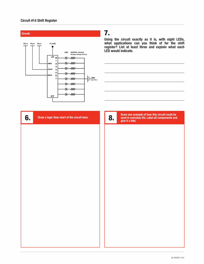
Using the circuit exactly as it is, with eight LEDs, what applications can you think of for the shift register? List at least three and explain what each LED would indicate.
Circuit:
Circuit #14 Shift Register
Draw a logic flow chart of the circuit here:Draw one example of how this circuit could be used in everyday life. Label all components and give it a title.
SIK BINDER //246
Soft potentiometers come in a bunch of shapes and sizes. Explain how you can combine multiple soft potentiometers to create a basic touchscreen interface with X and Y position output, or just go build one instead of explaining how it might work. You’ve finished the SIK, what are you waiting for? In fact, forget these guiding questions, if you want just use this page to brainstorm what your next project will be.
CHAPTER 6Tier 1 Difficulty Circuit #10 Soft Potentiometers

SIK BINDER //247
Circuit #10 Soft Potentiometers
SIK BINDER //248
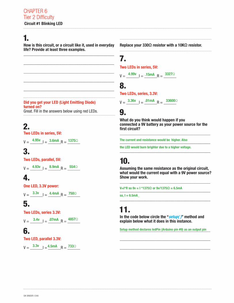
How is this circuit, or a circuit like it, used in everyday life? Provide at least three examples.___________________________________________
___________________________________________
___________________________________________
___________________________________________
___________________________________________
Did you get your LED (Light Emitting Diode) turned on? Great. Fill in the answers below using red LEDs.
Two LEDs in series, 5V: V = ______I = ______R = ______
Two LEDs, parallel, 5V: V = ______I = ______R = ______
One LED, 3.3V power: V = ______I = ______R = ______
Two LEDs, series 3.3V: V = ______I = ______R = ______
Two LED, parallel 3.3V:
V = ______I = ______R = ______
Replace your 330Ω resistor with a 10KΩ resistor.
Two LEDs in series, 5V: V = ______I = ______R = ______
Two LEDs, series, 3.3V:
V = ______I = ______R = ______
What do you think would happen if you conn ected a 9V battery as your power source for the first circuit? ___________________________________________
___________________________________________
___________________________________________
Assuming the same resistance as the original circuit, what would the current equal with a 9V power source? Show your work.___________________________________________
___________________________________________
___________________________________________
In the code below circle the “setup( )” method and explain below what it does in this instance.
___________________________________________
___________________________________________
___________________________________________
CHAPTER 6Tier 2 Difficulty Circuit #1 Blinking LED
1375Ω
554Ω
750Ω
4857Ω
733Ω
3327Ω
33600Ω
4.95v
4.93v
3.3v
3.4v
3.3v
4.99v
3.36v
3.6mA
8.9mA
4.4mA
.07mA
4.5mA
.15mA
.01mA
The current and resistance would be higher. Also
the LED would burn brighter due to a higher voltage.
Setup method declares ledPin (Arduino pin #9) as an output pin
V=I*R so 9v = I *1375Ω or 9v/1375Ω = 6.5mA
so, I = 6.5mA_
SIK BINDER //249
Circuit #1 Blinking LED
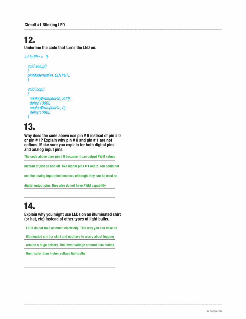
Underline the code that turns the LED on.
int ledPin = 9; void setup() { pinMode(ledPin, OUTPUT); } void loop() { analogWrite(ledPin, 200); delay(1000); analogWrite(ledPin, 0); delay(1000); }
Why does the code above use pin # 9 instead of pin # 0 or pin # 1? Explain why pin # 0 and pin # 1 are not options. Make sure you explain for both digital pins and analog input pins.
_________________________________________
_________________________________________
_________________________________________
_________________________________________
_________________________________________
Explain why you might use LEDs on an illuminated shirt (or hat, etc) instead of other types of light bulbs.
_________________________________________
_________________________________________
_________________________________________
_________________________________________
_________________________________________
LEDs do not take as much electricity. This way you can have an
illuminated shirt or skirt and not have to worry about lugging
around a huge battery. The lower voltage amount also makes
them safer than higher voltage lightbulbs
The code above uses pin # 9 because it can output PWM values
instead of just on and off like digital pins # 1 and 2. You could not
use the analog input pins because, although they can be used as
digital output pins, they also do not have PWM capability
SIK BINDER //250
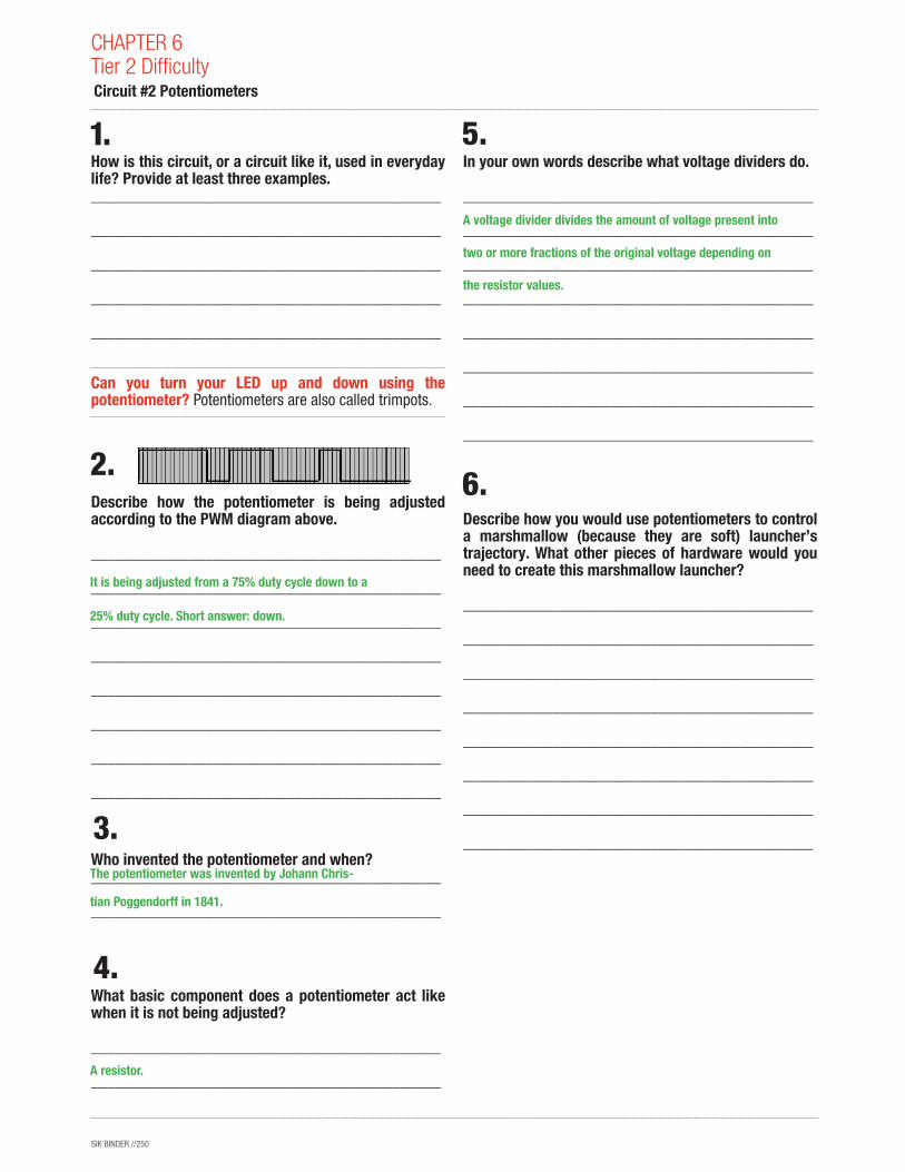
How is this circuit, or a circuit like it, used in everyday life? Provide at least three examples.___________________________________________
___________________________________________
___________________________________________
___________________________________________
___________________________________________
Can you turn your LED up and down using the potentiometer? Potentiometers are also called trimpots.
Describe how the potentiometer is being adjusted according to the PWM diagram above.
___________________________________________
___________________________________________
___________________________________________
___________________________________________
___________________________________________
___________________________________________
___________________________________________
___________________________________________
Who invented the potentiometer and when?___________________________________________
___________________________________________
What basic component does a potentiometer act like when it is not being adjusted?
___________________________________________
___________________________________________
In your own words describe what voltage dividers do.
___________________________________________
___________________________________________
___________________________________________
___________________________________________
___________________________________________
___________________________________________
___________________________________________
___________________________________________
Describe how you would use potentiometers to control a marshmallow (because they are soft) launcher’s trajectory. What other pieces of hardware would you need to create this marshmallow launcher?
___________________________________________
___________________________________________
___________________________________________
___________________________________________
___________________________________________
___________________________________________
___________________________________________
___________________________________________
CHAPTER 6Tier 2 Difficulty Circuit #2 Potentiometers
It is being adjusted from a 75% duty cycle down to a
25% duty cycle. Short answer: down.
The potentiometer was invented by Johann Chris-
tian Poggendorff in 1841.
A voltage divider divides the amount of voltage present into
two or more fractions of the original voltage depending on
the resistor values.
A resistor.
SIK BINDER //251
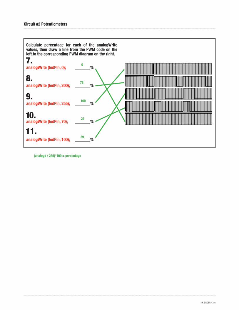
Calculate percentage for each of the analogWrite values, then draw a line from the PWM code on the left to the corresponding PWM diagram on the right.
analogWrite (ledPin, 0); _______%
analogWrite (ledPin, 200); _______%
analogWrite (ledPin, 255); _______%
analogWrite (ledPin, 70); _______%
analogWrite (ledPin, 100); _______%
Circuit #2 Potentiometers
0
78
100
27
39
(analog# / 255)*100 = percentage
SIK BINDER //252
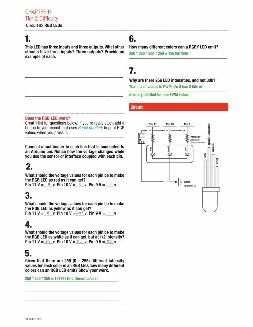
This LED has three inputs and three outputs. What other circuits have three inputs? Three outputs? Provide an example of each.
___________________________________________
___________________________________________
___________________________________________
___________________________________________
___________________________________________
Does the RGB LED work? Great. Hint for questions below: if you’re really stuck add a button to your circuit that uses Serial.println(); to print RGB values when you press it.
Connect a multimeter to each line that is connected to an Arduino pin. Notice how the voltage changes while you use the sensor or interface coupled with each pin.
What should the voltage values for each pin be to make the RGB LED as red as it can get?Pin 11 V =____v Pin 10 V =____v Pin 9 V =____v
What should the voltage values for each pin be to make the RGB LED as yellow as it can get?Pin 11 V =____v Pin 10 V =____v Pin 9 V =____v
What should the voltage values for each pin be to make the RGB LED as white as it can get, but at 1/2 intensity?Pin 11 V =____v Pin 10 V =____v Pin 9 V =____v
Given that there are 256 (0 – 255) different intensity values for each color in an RGB LED, how many different colors can an RGB LED emit? Show your work.
_________________________________________
_________________________________________
_________________________________________
How many different colors can a RGBY LED emit?
___________________________________________
Why are there 256 LED intensities, and not 300?
___________________________________________
Circuit:
CHAPTER 6Tier 2 Difficulty Circuit #3 RGB LEDs
0
2.5
0
0
2.5
2 to 3
5
2.5
5
256 * 256 * 256 = 16777216 different colors!
256 * 256 * 256 * 256 = 4294967296
That’s # of values in PWM b/c it has 8 bits of
memory allotted for one PWM value.
SIK BINDER //253
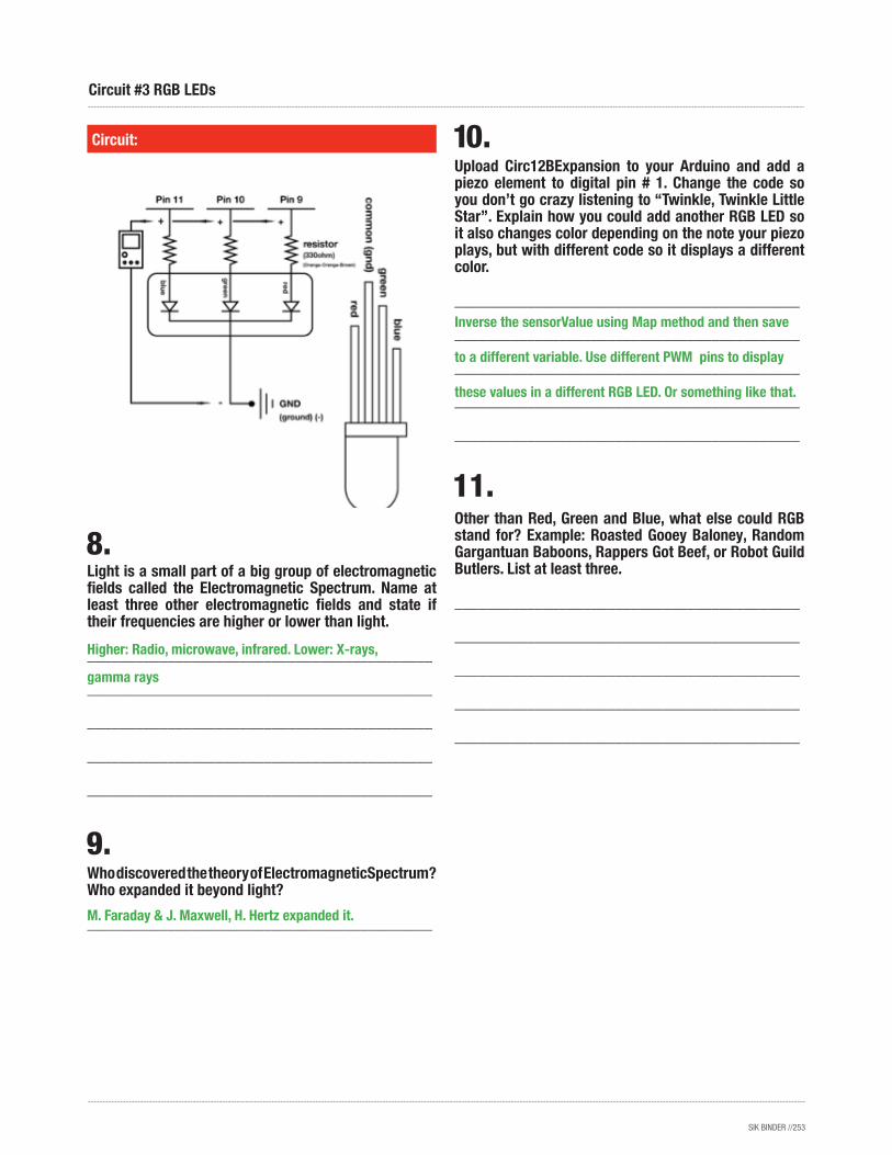
Light is a small part of a big group of electromagnetic fields called the Electromagnetic Spectrum. Name at least three other electromagnetic fields and state if their frequencies are higher or lower than light.
___________________________________________
___________________________________________
___________________________________________
___________________________________________
___________________________________________
Who discovered the theory of ElectromagneticSpectrum? Who expanded it beyond light?
___________________________________________
Circuit:
Circuit #3 RGB LEDs
Upload Circ12BExpansion to your Arduino and add a piezo element to digital pin # 1. Change the code so you don’t go crazy listening to “Twinkle, Twinkle Little Star”. Explain how you could add another RGB LED so it also changes color depending on the note your piezo plays, but with different code so it displays a different color.
___________________________________________
___________________________________________
___________________________________________
___________________________________________
___________________________________________
Other than Red, Green and Blue, what else could RGB stand for? Example: Roasted Gooey Baloney, Random Gargantuan Baboons, Rappers Got Beef, or Robot Guild Butlers. List at least three.
___________________________________________
___________________________________________
___________________________________________
___________________________________________
___________________________________________
Higher: Radio, microwave, infrared. Lower: X-rays,
gamma rays
Inverse the sensorValue using Map method and then save
to a different variable. Use different PWM pins to display
these values in a different RGB LED. Or something like that.
M. Faraday & J. Maxwell, H. Hertz expanded it.
SIK BINDER //254
How is this circuit, or a circuit like it, used in everyday life? Provide at least three examples._________________________________________
_________________________________________
_________________________________________
_________________________________________
_________________________________________
Did you get your LED turned on? Great. Now you are going to add a dimmer switch to your LED on pin # 9.
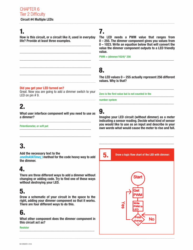
What user interface component will you need to use as a dimmer? _________________________________________
_________________________________________
_________________________________________
Add the necessary text to the oneOnAtATime( ) method for the code heavy way to add the dimmer.
There are three different ways to add a dimmer without changing or adding code. Try to find one of these ways without destroying your LED.
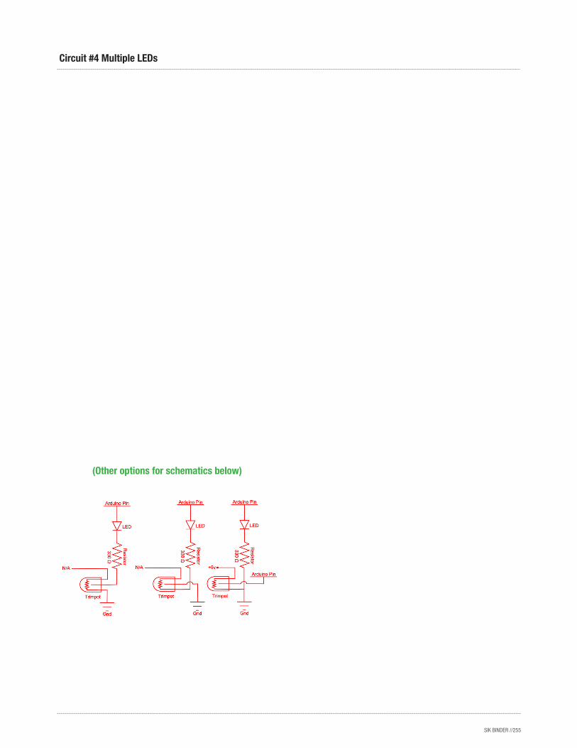
Draw a schematic of your circuit in the space to the right, adding your dimmer component so that it works. There are four different ways to do this.
What other component does the dimmer component in this circuit act as?
___________________________________________
The LED needs a PWM value that ranges from 0 – 255. The dimmer component gives you values from 0 – 1023. Write an equation below that will convert the value the dimmer component outputs to a LED friendly value.
___________________________________________
The LED values 0 – 255 actually represent 256 different values. Why is that?
___________________________________________
___________________________________________
___________________________________________
Imagine your LED circuit (without dimmer) as a meter indicating a sensor reading. Decide what kind of sensor you would like to use as an input and describe in your own words what would cause the meter to rise and fall.
___________________________________________
___________________________________________
Draw a logic flow chart of the LED with dimmer:
CHAPTER 6Tier 2 Difficulty Circuit #4 Multiple LEDs
Potentiometer, or soft pot
Resistor
PWM = (dimmer/1024)* 256
Zero is the first value but is not counted in the
number system
SIK BINDER //255
Circuit #4 Multiple LEDs
(Other options for schematics below)
SIK BINDER //256
How is this circuit, or a circuit like it, used in everyday life? Provide at least three examples.___________________________________________
___________________________________________
___________________________________________
___________________________________________
___________________________________________
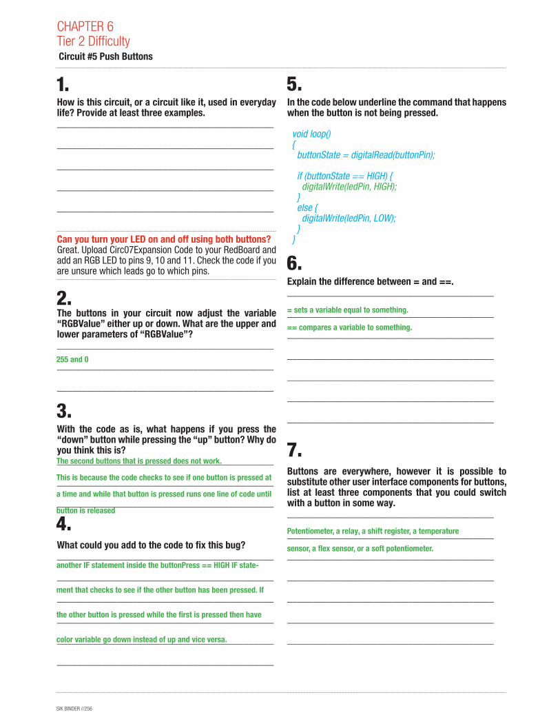
Can you turn your LED on and off using both buttons? Great. Upload Circ07Expansion Code to your RedBoard and add an RGB LED to pins 9, 10 and 11. Check the code if you are unsure which leads go to which pins.
The buttons in your circuit now adjust the variable “RGBValue” either up or down. What are the upper and lower parameters of “RGBValue”?___________________________________________
___________________________________________
___________________________________________
With the code as is, what happens if you press the “down” button while pressing the “up” button? Why do you think this is?___________________________________________
___________________________________________
___________________________________________
What could you add to the code to fix this bug?___________________________________________
___________________________________________
___________________________________________
___________________________________________
___________________________________________
___________________________________________
In the code below underline the command that happens when the button is not being pressed.
void loop() { buttonState = digitalRead(buttonPin);
if (buttonState == HIGH) { digitalWrite(ledPin, HIGH); } else { digitalWrite(ledPin, LOW); } }
Explain the difference between = and ==._________________________________________
_________________________________________
_________________________________________
_________________________________________
_________________________________________
_________________________________________
_________________________________________
Buttons are everywhere, however it is possible to substitute other user interface components for buttons, list at least three components that you could switch with a button in some way._________________________________________
_________________________________________
_________________________________________
_________________________________________
_________________________________________
_________________________________________
_________________________________________
CHAPTER 6Tier 2 Difficulty Circuit #5 Push Buttons
255 and 0
The second buttons that is pressed does not work.
This is because the code checks to see if one button is pressed at
a time and while that button is pressed runs one line of code until
button is released
Potentiometer, a relay, a shift register, a temperature
sensor, a flex sensor, or a soft potentiometer.
= sets a variable equal to something.
== compares a variable to something.
another IF statement inside the buttonPress == HIGH IF state-
ment that checks to see if the other button has been pressed. If
the other button is pressed while the first is pressed then have
color variable go down instead of up and vice versa.
SIK BINDER //257
Circuit #5 Push Buttons
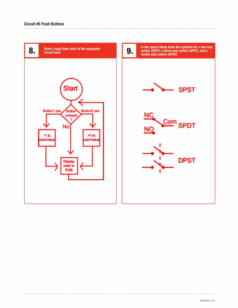
Draw a logic flow chart of the expanded circuit here:
In the space below draw the symbols for a two way switch (SPST), a three way switch (SPDT), and a double pole switch (DPST).
SIK BINDER //258
CHAPTER 6Tier 2 Difficulty
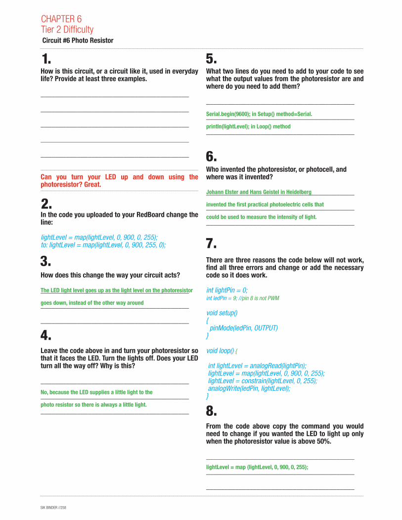
How is this circuit, or a circuit like it, used in everyday life? Provide at least three examples.
_________________________________________
_________________________________________
_________________________________________
_________________________________________
_________________________________________
Can you turn your LED up and down using the photoresistor? Great.
In the code you uploaded to your RedBoard change the line:
lightLevel = map(lightLevel, 0, 900, 0, 255); to: lightLevel = map(lightLevel, 0, 900, 255, 0);
How does this change the way your circuit acts?
_________________________________________
_________________________________________
_________________________________________
Leave the code above in and turn your photoresistor so that it faces the LED. Turn the lights off. Does your LED turn all the way off? Why is this?
_________________________________________
_________________________________________
_________________________________________
What two lines do you need to add to your code to see what the output values from the photoresistor are and where do you need to add them?
_________________________________________
_________________________________________
_________________________________________
Who invented the photoresistor, or photocell, and where was it invented?
_________________________________________
_________________________________________
_________________________________________
There are three reasons the code below will not work, find all three errors and change or add the necessary code so it does work.
int lightPin = 0; int ledPin = 9; //pin 8 is not PWM
void setup(){ pinMode(ledPin, OUTPUT)}
void loop() {
int lightLevel = analogRead(lightPin); lightLevel = map(lightLevel, 0, 900, 0, 255); lightLevel = constrain(lightLevel, 0, 255); analogWrite(ledPin, lightLevel); }
From the code above copy the command you would need to change if you wanted the LED to light up only when the photoresistor value is above 50%.
_________________________________________
_________________________________________
_________________________________________
Circuit #6 Photo Resistor
The LED light level goes up as the light level on the photoresistor
goes down, instead of the other way around
lightLevel = map (lightLevel, 0, 900, 0, 255);
No, because the LED supplies a little light to the
photo resistor so there is always a little light.
Serial.begin(9600); in Setup() method=Serial.
println(lightLevel); in Loop() method
Johann Elster and Hans Geistel in Heidelberg
invented the first practical photoelectric cells that
could be used to measure the intensity of light.
SIK BINDER //259
Circuit #6 Photo Resistor
Write below what you would need to change the command to so that it functions as described above.
_________________________________________
_________________________________________
_________________________________________
Photoresistors are great for light control, what else would you like to control with them? You can turn other circuits on or off by turning on your lights or opening your blinds. List at least three circuits.
_________________________________________
_________________________________________
_________________________________________
_________________________________________
_________________________________________
_________________________________________
_________________________________________
lightLevel = map (lightLevel, 450, 900, 0, 255);
Eyes (iris), morning glories (plants in general) and
Panamanian Golden Frog eggs (random!) I am sure
there are more too....
SIK BINDER //260
CHAPTER 6Tier 2 Difficulty
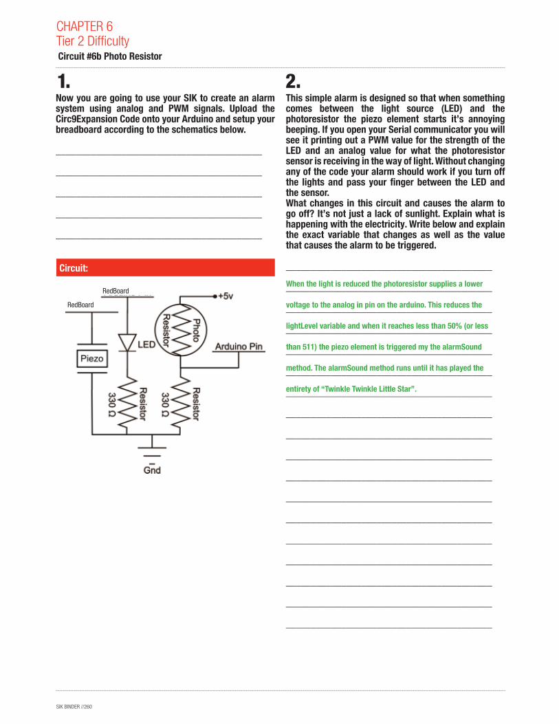
Now you are going to use your SIK to create an alarm system using analog and PWM signals. Upload the Circ9Expansion Code onto your Arduino and setup your breadboard according to the schematics below.
_________________________________________
_________________________________________
_________________________________________
_________________________________________
_________________________________________
This simple alarm is designed so that when something comes between the light source (LED) and the photoresistor the piezo element starts it’s annoying beeping. If you open your Serial communicator you will see it printing out a PWM value for the strength of the LED and an analog value for what the photoresistor sensor is receiving in the way of light. Without changing any of the code your alarm should work if you turn off the lights and pass your finger between the LED and the sensor.What changes in this circuit and causes the alarm to go off? It’s not just a lack of sunlight. Explain what is happening with the electricity. Write below and explain the exact variable that changes as well as the value that causes the alarm to be triggered.
_________________________________________
_________________________________________
_________________________________________
_________________________________________
_________________________________________
_________________________________________
_________________________________________
_________________________________________
_________________________________________
_________________________________________
_________________________________________
_________________________________________
_________________________________________
_________________________________________
_________________________________________
_________________________________________
_________________________________________
_________________________________________
Circuit:
Circuit #6b Photo Resistor
When the light is reduced the photoresistor supplies a lower
voltage to the analog in pin on the arduino. This reduces the
lightLevel variable and when it reaches less than 50% (or less
than 511) the piezo element is triggered my the alarmSound
method. The alarmSound method runs until it has played the
entirety of “Twinkle Twinkle Little Star”.
RedBoard
RedBoard
SIK BINDER //261
In order to make the alarm work during daylight you will need to be out of any direct lighting and you will need to change one of the values in the code. In the space below, write the line you changed in the code and explain why.
_________________________________________
_________________________________________
_________________________________________
_________________________________________
_________________________________________
_________________________________________
_________________________________________
_________________________________________
What component in the SIK do you think you could use to physically change the sensitivity of the photoresistor so you don’t have to change the code whenever the sunlight levels change? Explain how.
_________________________________________
_________________________________________
_________________________________________
_________________________________________
_________________________________________
_________________________________________
_________________________________________
Circuit #6b Photo Resistor
if(lightLevel < 511 { should be changed to if (lightLevel < 750{
so that the light doesn’t need to go down as much in order for
the alarmSound method to be triggered (value may be differ-
ent than 750). This is because there is ambient light that is not
emitted by the LED so we need to compensate for that.
You can use a potentiometer to change the resistance of
the photoresistor circuit. This way if there is more sunlight
you could turn up the potentiometer, thereby decreasing
the voltage the circuit emits and vice versa.
SIK BINDER //262
How is this circuit, or a circuit like it, used in everyday life? Provide at least three examples.
___________________________________________
___________________________________________
___________________________________________
___________________________________________
___________________________________________
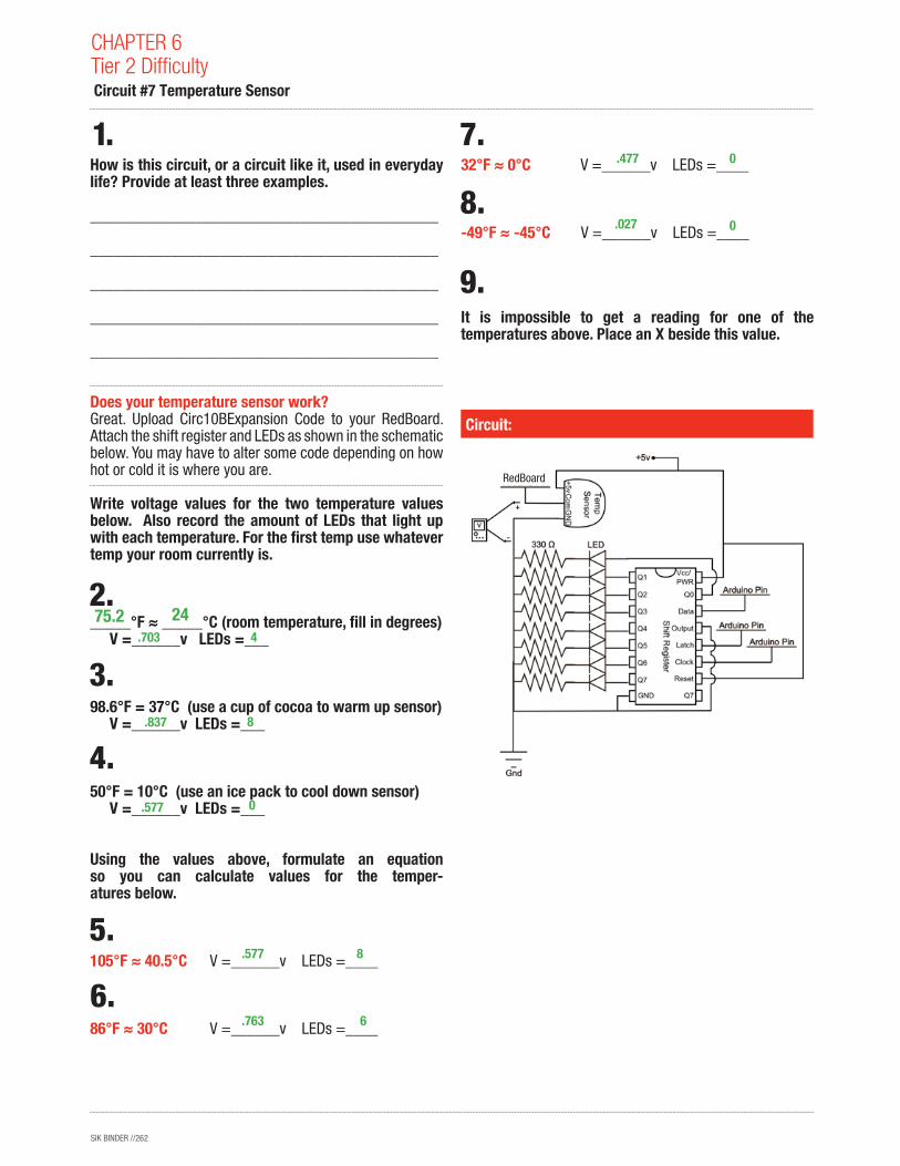
Does your temperature sensor work? Great. Upload Circ10BExpansion Code to your RedBoard. Attach the shift register and LEDs as shown in the schematic below. You may have to alter some code depending on how hot or cold it is where you are.
Write voltage values for the two temperature values below. Also record the amount of LEDs that light up with each temperature. For the first temp use whatever temp your room currently is.
_____°F ≈ _____°C (room temperature, fill in degrees) V =______v LEDs =___
98.6°F = 37°C (use a cup of cocoa to warm up sensor) V =______v LEDs =___
50°F = 10°C (use an ice pack to cool down sensor) V =______v LEDs =___
Using the values above, formulate an equation so you can calculate values for the temper- atures below.
105°F ≈ 40.5°C V =______v LEDs =____
86°F ≈ 30°C V =______v LEDs =____
32°F ≈ 0°C V =______v LEDs =____
-49°F ≈ -45°C V =______v LEDs =____
It is impossible to get a reading for one of the temperatures above. Place an X beside this value.
Circuit:
CHAPTER 6Tier 2 Difficulty Circuit #7 Temperature Sensor
.703
.837
.577
.577
.763
.477
.027
4
8
8
6
0
0
0
75.2 24
RedBoard
SIK BINDER //263
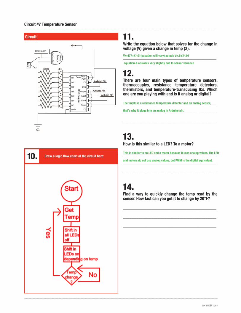
Write the equation below that solves for the change in voltage (V) given a change in temp (X).
___________________________________________
There are four main types of temperature sensors, thermocouples, resistance temperature detectors, thermistors, and temperature-transducing ICs. Which one are you playing with and is it analog or digital?
___________________________________________
___________________________________________
___________________________________________
How is this similar to a LED? To a motor?
___________________________________________
___________________________________________
___________________________________________
Find a way to quickly change the temp read by the sensor. How fast can you get it to change by 20°F?
___________________________________________
___________________________________________
___________________________________________
Circuit:
Circuit #7 Temperature Sensor
Draw a logic flow chart of the circuit here:
V≈.477+X*.01(equation will vary) actual: V=.5+X*.01
equation & answers vary slightly due to sensor variance
The tmp36 is a resistance temperature detector and an analog sensor,
that’s why it plugs into an analog in Arduino pin.
This is similar to an LED and a motor because it uses analog values. The LED
and motors do not use analog values, but PWM is the digital equivalent.
RedBoard
SIK BINDER //264
How is this circuit, or a circuit like it, used in everyday life? Provide at least three examples.___________________________________________
___________________________________________
___________________________________________
___________________________________________
___________________________________________
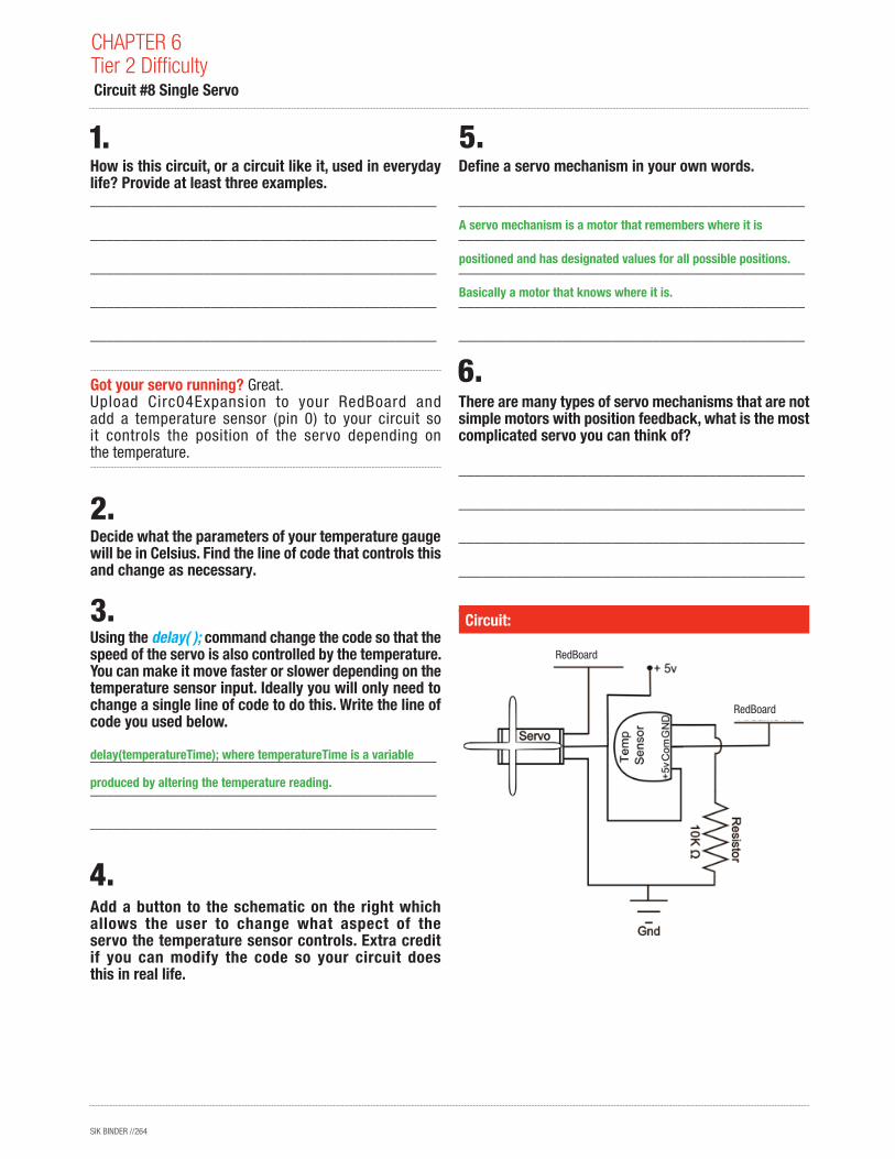
Got your servo running? Great. Upload Circ04Expansion to your RedBoard and add a temperature sensor (pin 0) to your circuit so it controls the position of the servo depending on the temperature.
Decide what the parameters of your temperature gauge will be in Celsius. Find the line of code that controls this and change as necessary.
Using the delay( ); command change the code so that the speed of the servo is also controlled by the temperature. You can make it move faster or slower depending on the temperature sensor input. Ideally you will only need to change a single line of code to do this. Write the line of code you used below.
___________________________________________
___________________________________________
___________________________________________
Add a button to the schematic on the right which allows the user to change what aspect of the servo the temperature sensor controls. Extra credit if you can modify the code so your circuit does this in real life.
Define a servo mechanism in your own words.
___________________________________________
___________________________________________
___________________________________________
___________________________________________
___________________________________________
There are many types of servo mechanisms that are not simple motors with position feedback, what is the most complicated servo you can think of?
___________________________________________
___________________________________________
___________________________________________
___________________________________________
___________________________________________Circuit:
CHAPTER 6Tier 2 Difficulty Circuit #8 Single Servo
delay(temperatureTime); where temperatureTime is a variable
produced by altering the temperature reading.
A servo mechanism is a motor that remembers where it is
positioned and has designated values for all possible positions.
Basically a motor that knows where it is.
RedBoard
RedBoard
SIK BINDER //265
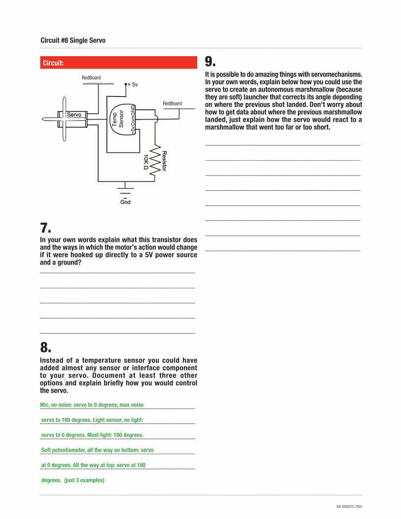
In your own words explain what this transistor does and the ways in which the motor’s action would change if it were hooked up directly to a 5V power source and a ground?___________________________________________
___________________________________________
___________________________________________
___________________________________________
___________________________________________
Instead of a temperature sensor you could have added almost any sensor or interface component to your servo. Document at least three other options and explain briefly how you would control the servo.
___________________________________________
___________________________________________
___________________________________________
___________________________________________
___________________________________________
Circuit:
Circuit #8 Single Servo
It is possible to do amazing things with servomechanisms. In your own words, explain below how you could use the servo to create an autonomous marshmallow (because they are soft) launcher that corrects its angle depending on where the previous shot landed. Don’t worry about how to get data about where the previous marshmallow landed, just explain how the servo would react to a marshmallow that went too far or too short.
___________________________________________
___________________________________________
___________________________________________
___________________________________________
___________________________________________
___________________________________________
___________________________________________
___________________________________________
Mic, no noise: servo to 0 degrees, max noise
servo to 180 degrees. Light sensor, no light:
servo to 0 degrees. Most light: 180 degrees.
Soft potentiometer, all the way on bottom: servo
at 0 degrees. All the way at top: servo at 180
degrees. (just 3 examples)
RedBoard
RedBoard
SIK BINDER //266
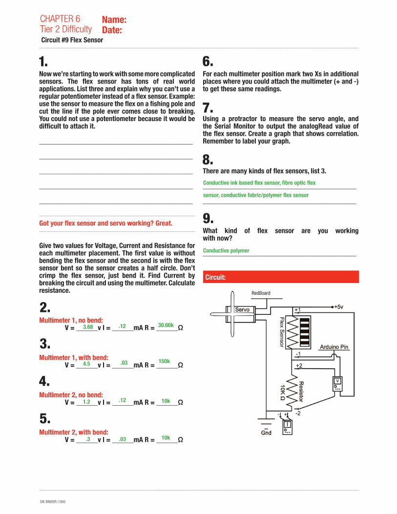
Now we’re starting to work with some more complicated sensors. The flex sensor has tons of real world applications. List three and explain why you can’t use a regular potentiometer instead of a flex sensor. Example: use the sensor to measure the flex on a fishing pole and cut the line if the pole ever comes close to breaking. You could not use a potentiometer because it would be difficult to attach it.
___________________________________________
___________________________________________
___________________________________________
___________________________________________
___________________________________________
Got your flex sensor and servo working? Great.
Give two values for Voltage, Current and Resistance for each multimeter placement. The first value is without bending the flex sensor and the second is with the flex sensor bent so the sensor creates a half circle. Don’t crimp the flex sensor, just bend it. Find Current by breaking the circuit and using the multimeter. Calculate resistance.
Multimeter 1, no bend: V = ______v I = ______mA R = ______Ω
Multimeter 1, with bend: V = ______v I = ______mA R = ______Ω
Multimeter 2, no bend: V = ______v I = ______mA R = ______Ω
Multimeter 2, with bend: V = ______v I = ______mA R = ______Ω
For each multimeter position mark two Xs in additional places where you could attach the multimeter (+ and -) to get these same readings.
Using a protractor to measure the servo angle, and the Serial Monitor to output the analogRead value of the flex sensor. Create a graph that shows correlation. Remember to label your graph.
There are many kinds of flex sensors, list 3.
___________________________________________
___________________________________________
What kind of flex sensor are you working with now?
___________________________________________
Circuit:
CHAPTER 6Tier 2 Difficulty Circuit #9 Flex Sensor
Name:Date:
3.68
4.5
1.2
.3
.12
.03
.12
.03
30.66k
150k
10k
10k
Conductive ink based flex sensor, fibre optic flex
sensor, conductive fabric/polymer flex sensor
Conductive polymer
RedBoard
SIK BINDER //267
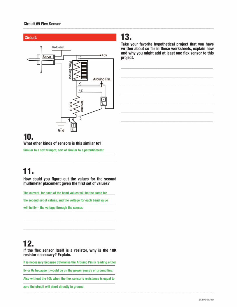
What other kinds of sensors is this similar to?
___________________________________________
___________________________________________
How could you figure out the values for the second multimeter placement given the first set of values?
___________________________________________
___________________________________________
___________________________________________
___________________________________________
___________________________________________
If the flex sensor itself is a resistor, why is the 10K resistor necessary? Explain.
___________________________________________
___________________________________________
___________________________________________
Take your favorite hypothetical project that you have written about so far in these worksheets, explain how and why you might add at least one flex sensor to this project.
___________________________________________
___________________________________________
___________________________________________
___________________________________________
___________________________________________
___________________________________________
___________________________________________
Circuit:
Circuit #9 Flex Sensor
The current for each of the bend values will be the same for
the second set of values, and the voltage for each bend value
will be 5v – the voltage through the sensor.
It is necessary because otherwise the Arduino Pin is reading either
5v or 0v because it would be on the power source or ground line.
Also without the 10k when the flex sensor’s resistance is equal to
zero the circuit will short directly to ground.
Similar to a soft trimpot, sort of similar to a potentiometer.
RedBoard
SIK BINDER //268
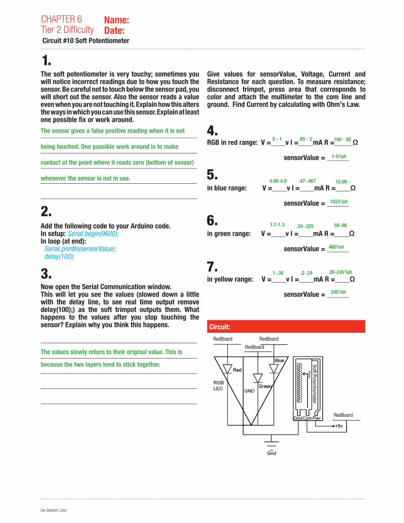
The soft potentiometer is very touchy; sometimes you will notice incorrect readings due to how you touch the sensor. Be careful not to touch below the sensor pad, you will short out the sensor. Also the sensor reads a value even when you are not touching it. Explain how this alters the ways in which you can use this sensor. Explain at least one possible fix or work around.
___________________________________________
___________________________________________
___________________________________________
___________________________________________
___________________________________________
Add the following code to your Arduino code.In setup: Serial.begin(9600);In loop (at end): Serial.println(sensorValue); delay(100);
Now open the Serial Communication window.This will let you see the values (slowed down a little with the delay line, to see real time output remove delay(100);) as the soft trimpot outputs them. What happens to the values after you stop touching the sensor? Explain why you think this happens.
___________________________________________
___________________________________________
___________________________________________
___________________________________________
___________________________________________
Give values for sensorValue, Voltage, Current and Resistance for each question. To measure resistance; disconnect trimpot, press area that corresponds to color and attach the multimeter to the com line and ground. Find Current by calculating with Ohm’s Law.
RGB in red range: V =____v I =____mA R =_____Ω
sensorValue = ______
in blue range: V =____v I =____mA R =____Ω
sensorValue = ______
in green range: V =____v I =____mA R =____Ω
sensorValue = ______
in yellow range: V =____v I =____mA R =____Ω
sensorValue = ______
Circuit:
CHAPTER 6Tier 2 Difficulty Circuit #10 Soft Potentiometer
Name:Date:
The sensor gives a false positive reading when it is not
being touched. One possible work around is to make
contact at the point where it reads zero (bottom of sensor)
whenever the sensor is not in use.
The values slowly return to their original value. This is
because the two layers tend to stick together.
5 - 1
4.99-4.9
1.7-1.3
1-.36
.05 - 2
.47-.467
.34-.325
.2-.24
100 - 50
10.6K -
5K-4K
2K-245’ish
1-0’ish
1023’ish
460’ish
245’ish
RedBoard RedBoard
RedBoard
RedBoard
SIK BINDER //269
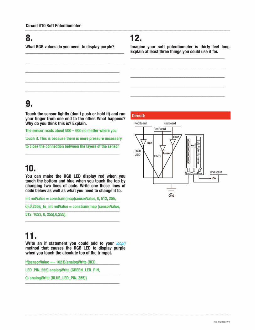
What RGB values do you need to display purple?___________________________________________
___________________________________________
_________________________________________
_________________________________________
_________________________________________
Touch the sensor lightly (don’t push or hold it) and run your finger from one end to the other. What happens? Why do you think this is? Explain.
_________________________________________
_________________________________________
_________________________________________
You can make the RGB LED display red when you touch the bottom and blue when you touch the top by changing two lines of code. Write one these lines of code below as well as what you need to change it to.
_________________________________________
_________________________________________
_________________________________________
Write an if statement you could add to your loop() method that causes the RGB LED to display purple when you touch the absolute top of the trimpot.
_________________________________________
_________________________________________
_________________________________________
Imagine your soft potentiometer is thirty feet long. Explain at least three things you could use it for._________________________________________
_________________________________________
_________________________________________
_________________________________________
_________________________________________
Circuit #10 Soft Potentiometer
Circuit:
The sensor reads about 500 – 600 no matter where you
touch it. This is because there is more pressure necessary
to close the connection between the layers of the sensor
int redValue = constrain(map(sensorValue, 0, 512, 255,
0),0,255);_to_int redValue = constrain(map (sensorValue,
512, 1023, 0, 255),0,255);
if(sensorValue == 1023){analogWrite (RED_
LED_PIN, 255) analogWrite (GREEN_LED_PIN,
0) analogWrite (BLUE_LED_PIN, 255)}
RedBoard RedBoard
RedBoard
RedBoard
SIK BINDER //270
How is this circuit, or a circuit like it, used in everyday life? Provide at least three examples.___________________________________________
___________________________________________
___________________________________________
___________________________________________
___________________________________________
Got your incredibly annoying song blaring out of your tiny speaker? Great.
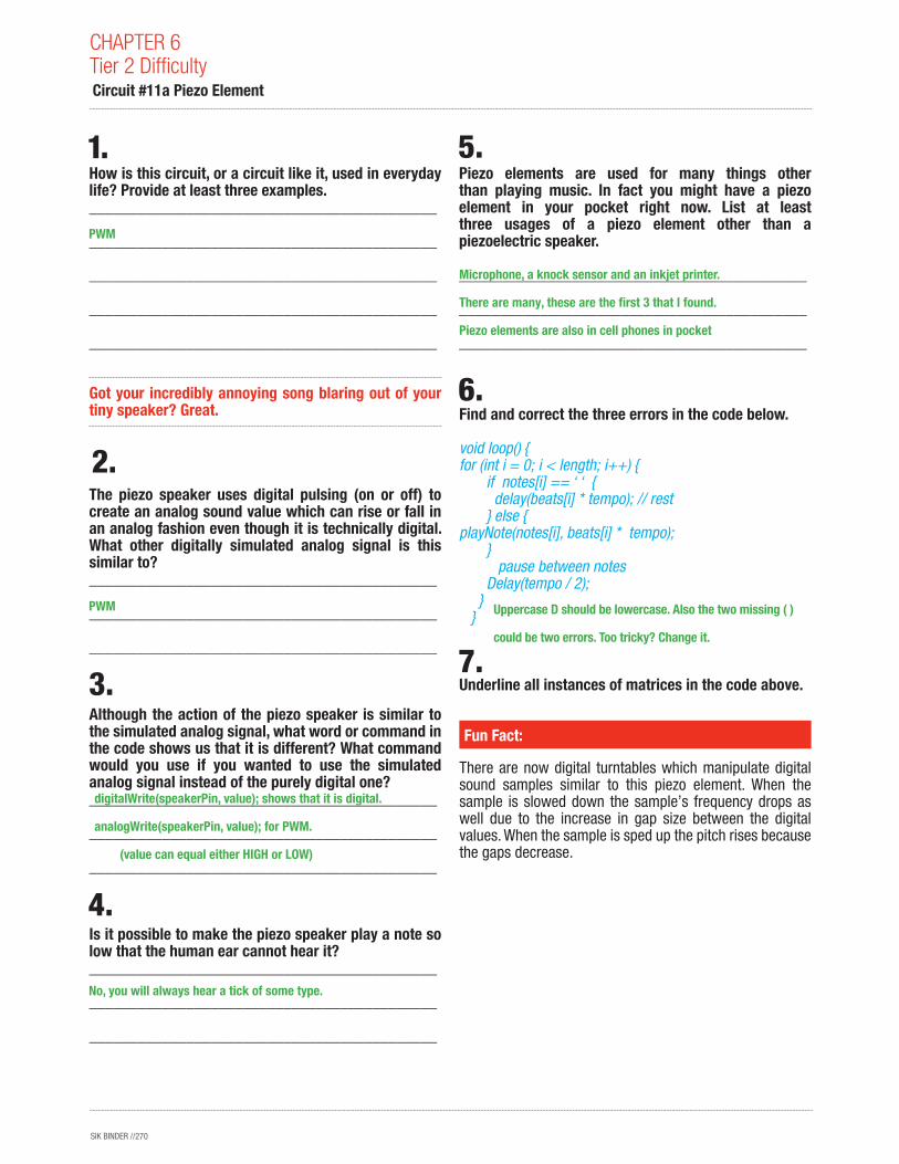
The piezo speaker uses digital pulsing (on or off) to create an analog sound value which can rise or fall in an analog fashion even though it is technically digital. What other digitally simulated analog signal is this similar to?___________________________________________
___________________________________________
___________________________________________
Although the action of the piezo speaker is similar to the simulated analog signal, what word or command in the code shows us that it is different? What command would you use if you wanted to use the simulated analog signal instead of the purely digital one?___________________________________________
___________________________________________
___________________________________________
Is it possible to make the piezo speaker play a note so low that the human ear cannot hear it?___________________________________________
___________________________________________
___________________________________________
Piezo elements are used for many things other than playing music. In fact you might have a piezo element in your pocket right now. List at least three usages of a piezo element other than a piezoelectric speaker.
___________________________________________
___________________________________________
___________________________________________
Find and correct the three errors in the code below.
void loop() {for (int i = 0; i < length; i++) { if notes[i] == ‘ ‘ { delay(beats[i] * tempo); // rest } else {playNote(notes[i], beats[i] * tempo); } pause between notes Delay(tempo / 2); } }
Underline all instances of matrices in the code above.
There are now digital turntables which manipulate digital sound samples similar to this piezo element. When the sample is slowed down the sample’s frequency drops as well due to the increase in gap size between the digital values. When the sample is sped up the pitch rises because the gaps decrease.
Fun Fact:
CHAPTER 6Tier 2 Difficulty Circuit #11a Piezo Element
PWM
PWM
digitalWrite(speakerPin, value); shows that it is digital.
analogWrite(speakerPin, value); for PWM.
(value can equal either HIGH or LOW)
Microphone, a knock sensor and an inkjet printer.
There are many, these are the first 3 that I found.
Piezo elements are also in cell phones in pocket
Uppercase D should be lowercase. Also the two missing ( )
could be two errors. Too tricky? Change it.
No, you will always hear a tick of some type.
SIK BINDER //271
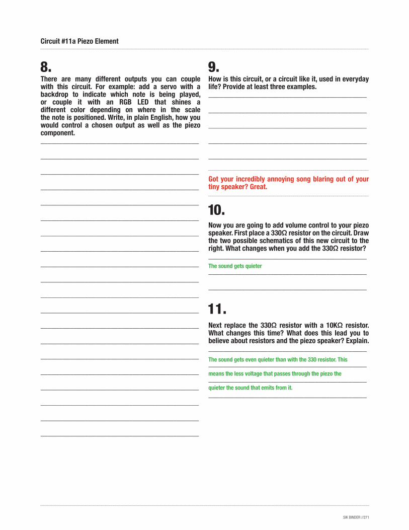
How is this circuit, or a circuit like it, used in everyday life? Provide at least three examples.___________________________________________
___________________________________________
___________________________________________
___________________________________________
___________________________________________
Got your incredibly annoying song blaring out of your tiny speaker? Great.
Now you are going to add volume control to your piezo speaker. First place a 330Ω resistor on the circuit. Draw the two possible schematics of this new circuit to the right. What changes when you add the 330Ω resistor?___________________________________________
___________________________________________
___________________________________________
Next replace the 330Ω resistor with a 10KΩ resistor. What changes this time? What does this lead you to believe about resistors and the piezo speaker? Explain.___________________________________________
___________________________________________
___________________________________________
___________________________________________
There are many different outputs you can couple with this circuit. For example: add a servo with a backdrop to indicate which note is being played, or couple it with an RGB LED that shines a different color depending on where in the scale the note is positioned. Write, in plain English, how you would control a chosen output as well as the piezo component.___________________________________________
___________________________________________
___________________________________________
___________________________________________
___________________________________________
___________________________________________
___________________________________________
___________________________________________
___________________________________________
___________________________________________
___________________________________________
___________________________________________
___________________________________________
___________________________________________
___________________________________________
___________________________________________
___________________________________________
___________________________________________
___________________________________________
___________________________________________
Circuit #11a Piezo Element
The sound gets quieter
The sound gets even quieter than with the 330 resistor. This
means the less voltage that passes through the piezo the
quieter the sound that emits from it.
SIK BINDER //272
CHAPTER 6Tier 2 Difficulty Circuit #11 Piezo Element
Now replace the resistor with the potentiometer. Measure the resistance of the potentiometer and write below the lowest resistance value it can be set to and the highest resistance value it can be set to.
Lowest resistance: _______________ Ω
Highest resistance: _______________ Ω
But wait! Can’t we just turn down the volume using a lower PWM value in the code? Why are we changing resistors when it’s so much easier to just rewrite the code a little? Find the line of code you will need to change to try using PWM to control the volume instead of a resistor and write it below.
___________________________________________
___________________________________________
___________________________________________
Now actually change the code and listen to the results. Can’t hear any difference? Try using a lower PWM value. You should definitely notice a difference now. That’s different from changing the volume right? Now use your potentiometer to change the PWM value of the piezo speaker circuit. You will need to change the code to do this. Write the three essential lines of code you used to make this happen below, don’t forget semicolons. (Hint, one of them is a variable declaration before the setup() method.)___________________________________________
___________________________________________
___________________________________________
Does your piezo speaker turn off when you turn your potentiometer all the way one way? This is because the analog values go up to 1023 but the PWM only go to 255. You can use the map() method to fix this. Write the line of code which will fix the problem below. (If it still turns off with map, make sure your PWM value never goes all the way down to zero.)
___________________________________________
___________________________________________
___________________________________________
The effect that changing the PWM has on “Twinkle, Twinkle Little Star” is kind of like an effect that many musicians use in on their instruments in modern music. What is that effect?___________________________________________
___________________________________________
___________________________________________
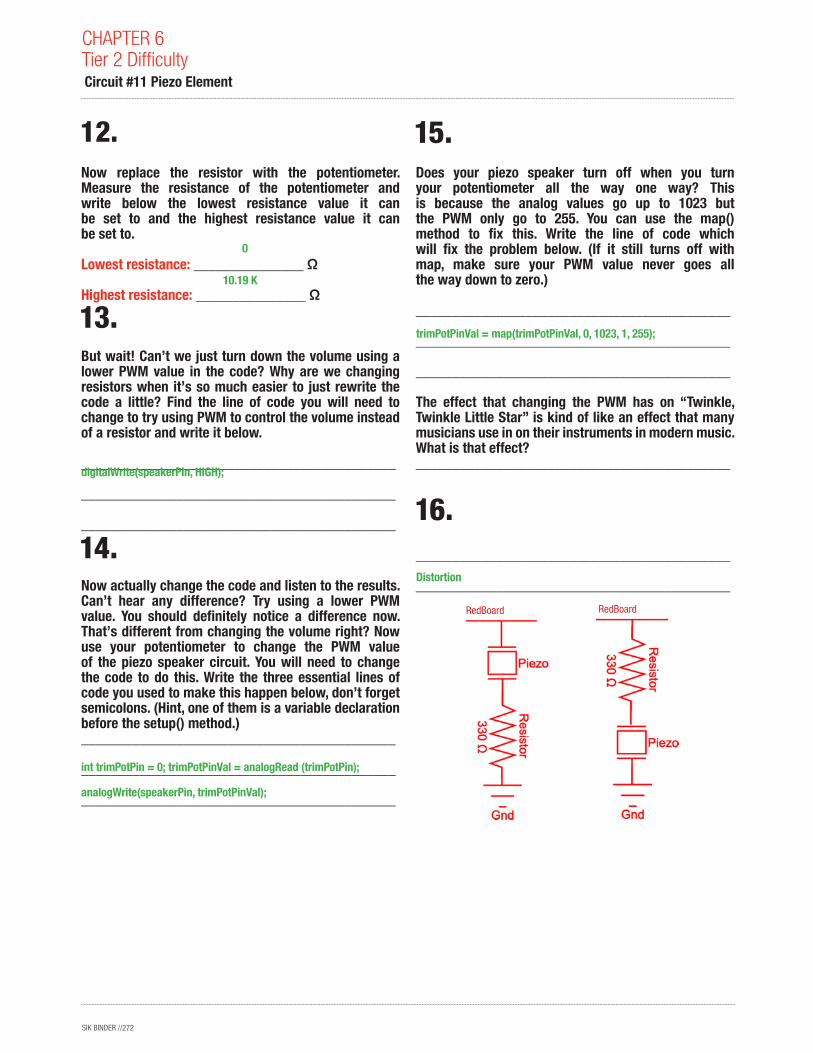
16.
int trimPotPin = 0; trimPotPinVal = analogRead (trimPotPin);
analogWrite(speakerPin, trimPotPinVal);
trimPotPinVal = map(trimPotPinVal, 0, 1023, 1, 255);
Distortion
digitalWrite(speakerPin, HIGH);
0
10.19 K
RedBoard RedBoard

SIK BINDER //273
Circuit #11b Piezo Element
SIK BINDER //274
How is this circuit, or a circuit like it, used in everyday life? Provide at least three examples.___________________________________________
___________________________________________
___________________________________________
___________________________________________
___________________________________________
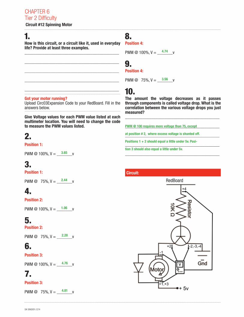
Got your motor running? Upload Circ03Expansion Code to your RedBoard. Fill in the answers below.
Give Voltage values for each PWM value listed at each multimeter location. You will need to change the code to measure the PWM values listed.
Position 1: PWM @ 100%, V = _______v
Position 1: PWM @ 75%, V = _______v
Position 2: PWM @ 100%, V = _______v
Position 2: PWM @ 75%, V = _______v
Position 3:
PWM @ 100%, V = _______v
Position 3:
PWM @ 75%, V = _______v
Position 4:
PWM @ 100%, V = _______v
Position 4:
PWM @ 75%, V = _______v
The amount the voltage decreases as it passes through components is called voltage drop. What is the correlation between the various voltage drops you just measured?___________________________________________
___________________________________________
___________________________________________
___________________________________________
___________________________________________
Circuit:
CHAPTER 6Tier 2 Difficulty Circuit #12 Spinning Motor
3.65
2.44
1.06
2.28
4.76
4.81
4.74
3.56
PWM @ 100 requires more voltage than 75, except
at position # 2, where excess voltage is shunted off.
Positions 1 + 2 should equal a little under 5v. Posi-
tion 3 should also equal a little under 5v.
RedBoard
SIK BINDER //275
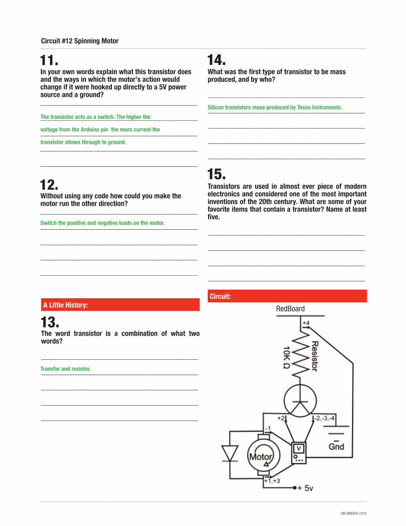
The word transistor is a combination of what two words?
___________________________________________
___________________________________________
___________________________________________
___________________________________________
___________________________________________
Circuit:A Little History:
Circuit #12 Spinning Motor
In your own words explain what this transistor does and the ways in which the motor’s action would change if it were hooked up directly to a 5V power source and a ground?___________________________________________
___________________________________________
___________________________________________
___________________________________________
___________________________________________
Without using any code how could you make the motor run the other direction?___________________________________________
___________________________________________
___________________________________________
___________________________________________
___________________________________________
What was the first type of transistor to be mass produced, and by who?
___________________________________________
___________________________________________
___________________________________________
___________________________________________
___________________________________________
Transistors are used in almost ever piece of modern electronics and considered one of the most important inventions of the 20th century. What are some of your favorite items that contain a transistor? Name at least five.
___________________________________________
___________________________________________
___________________________________________
___________________________________________
The transistor acts as a switch. The higher the
voltage from the Arduino pin the more current the
transistor allows through to ground.
Switch the positive and negative leads on the motor.
Transfer and resistor.
Silicon transistors mass produced by Texas Instruments.
RedBoard
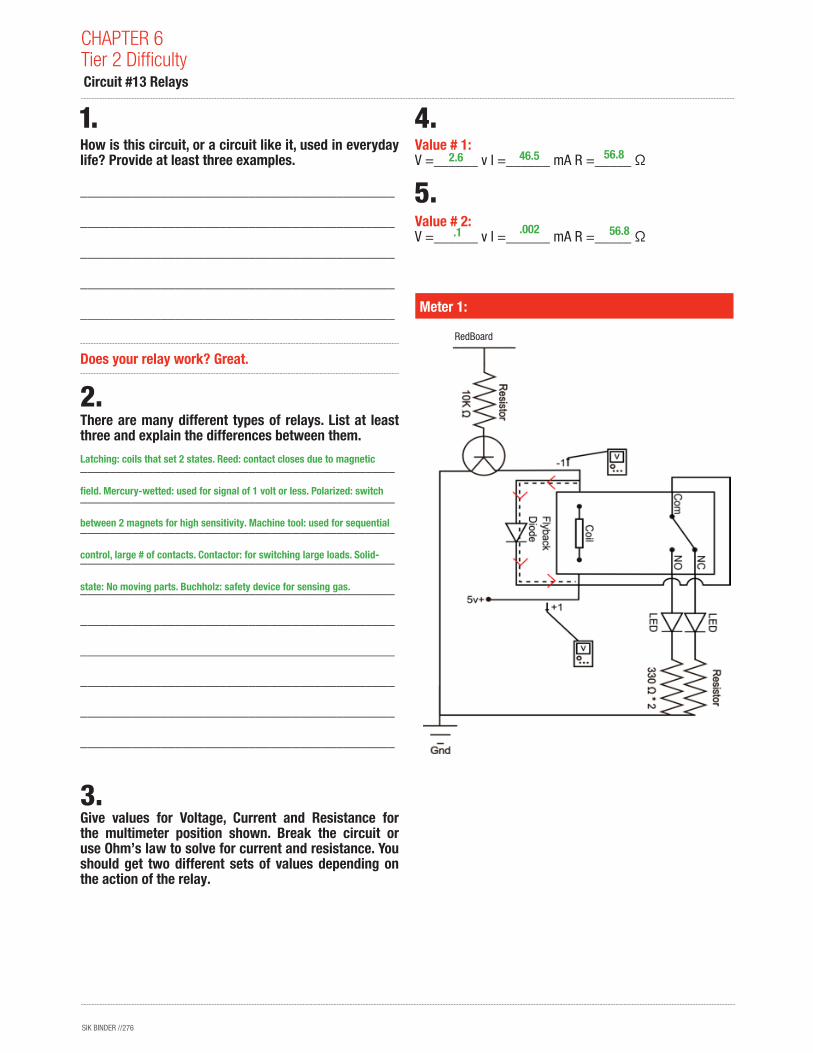
SIK BINDER //276
How is this circuit, or a circuit like it, used in everyday life? Provide at least three examples.
___________________________________________
___________________________________________
___________________________________________
___________________________________________
___________________________________________
Does your relay work? Great.
There are many different types of relays. List at least three and explain the differences between them.
___________________________________________
___________________________________________
___________________________________________
___________________________________________
___________________________________________
___________________________________________
___________________________________________
___________________________________________
___________________________________________
___________________________________________
Give values for Voltage, Current and Resistance for the multimeter position shown. Break the circuit or use Ohm’s law to solve for current and resistance. You should get two different sets of values depending on the action of the relay.
Value # 1: V =______ v I =______ mA R =_____ Ω
Value # 2: V =______ v I =______ mA R =_____ Ω
Meter 1:
CHAPTER 6Tier 2 Difficulty Circuit #13 Relays
2.6
.1
46.5
.002
56.8
56.8
Latching: coils that set 2 states. Reed: contact closes due to magnetic
field. Mercury-wetted: used for signal of 1 volt or less. Polarized: switch
between 2 magnets for high sensitivity. Machine tool: used for sequential
control, large # of contacts. Contactor: for switching large loads. Solid-
state: No moving parts. Buchholz: safety device for sensing gas.
RedBoard
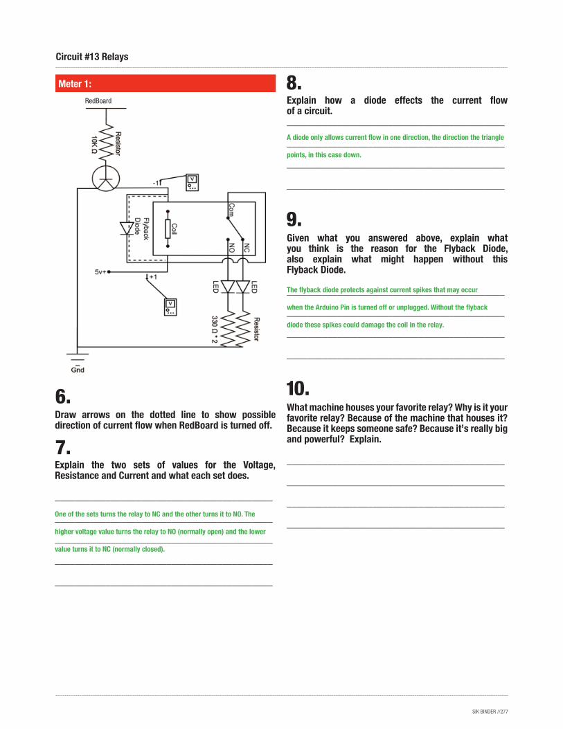
SIK BINDER //277
Explain the two sets of values for the Voltage, Resistance and Current and what each set does.
___________________________________________
___________________________________________
___________________________________________
___________________________________________
___________________________________________
Meter 1:
Draw arrows on the dotted line to show possible direction of current flow when RedBoard is turned off.
Circuit #13 Relays
Explain how a diode effects the current flow of a circuit.___________________________________________
___________________________________________
___________________________________________
___________________________________________
Given what you answered above, explain what you think is the reason for the Flyback Diode, also explain what might happen without this Flyback Diode.
___________________________________________
___________________________________________
___________________________________________
___________________________________________
What machine houses your favorite relay? Why is it your favorite relay? Because of the machine that houses it? Because it keeps someone safe? Because it’s really big and powerful? Explain.
___________________________________________
___________________________________________
___________________________________________
___________________________________________One of the sets turns the relay to NC and the other turns it to NO. The
higher voltage value turns the relay to NO (normally open) and the lower
value turns it to NC (normally closed).
A diode only allows current flow in one direction, the direction the triangle
points, in this case down.
The flyback diode protects against current spikes that may occur
when the Arduino Pin is turned off or unplugged. Without the flyback
diode these spikes could damage the coil in the relay.
RedBoard
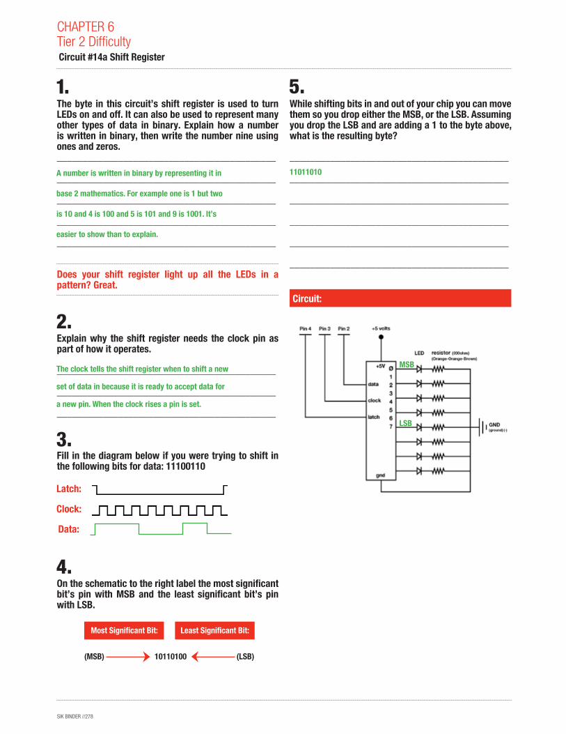
SIK BINDER //278
The byte in this circuit’s shift register is used to turn LEDs on and off. It can also be used to represent many other types of data in binary. Explain how a number is written in binary, then write the number nine using ones and zeros.___________________________________________
___________________________________________
___________________________________________
___________________________________________
___________________________________________
Does your shift register light up all the LEDs in a pattern? Great.
Explain why the shift register needs the clock pin as part of how it operates.
___________________________________________
___________________________________________
___________________________________________
Fill in the diagram below if you were trying to shift in the following bits for data: 11100110
On the schematic to the right label the most significant bit’s pin with MSB and the least significant bit’s pin with LSB.
While shifting bits in and out of your chip you can move them so you drop either the MSB, or the LSB. Assuming you drop the LSB and are adding a 1 to the byte above, what is the resulting byte?
___________________________________________
___________________________________________
___________________________________________
___________________________________________
___________________________________________
___________________________________________
Circuit:
Latch:
Clock:
Data:
Most Significant Bit: Least Significant Bit:
10110100(MSB) (LSB)
CHAPTER 6Tier 2 Difficulty Circuit #14a Shift Register
A number is written in binary by representing it in
base 2 mathematics. For example one is 1 but two
is 10 and 4 is 100 and 5 is 101 and 9 is 1001. It’s
easier to show than to explain.
The clock tells the shift register when to shift a new
set of data in because it is ready to accept data for
a new pin. When the clock rises a pin is set.
11011010
MSB
LSB
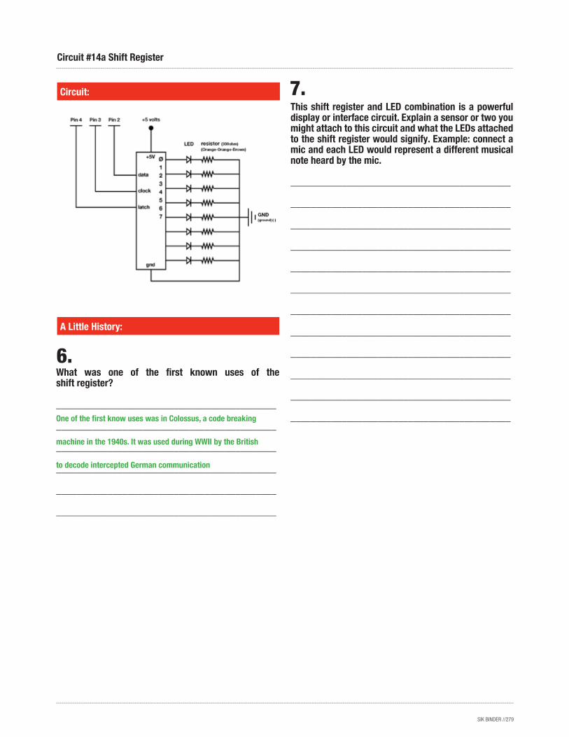
SIK BINDER //279
This shift register and LED combination is a powerful display or interface circuit. Explain a sensor or two you might attach to this circuit and what the LEDs attached to the shift register would signify. Example: connect a mic and each LED would represent a different musical note heard by the mic.
___________________________________________
___________________________________________
___________________________________________
___________________________________________
___________________________________________
___________________________________________
___________________________________________
___________________________________________
___________________________________________
___________________________________________
___________________________________________
___________________________________________
What was one of the first known uses of the shift register?
___________________________________________
___________________________________________
___________________________________________
___________________________________________
___________________________________________
___________________________________________
Circuit:
A Little History:
Circuit #14a Shift Register
One of the first know uses was in Colossus, a code breaking
machine in the 1940s. It was used during WWII by the British
to decode intercepted German communication
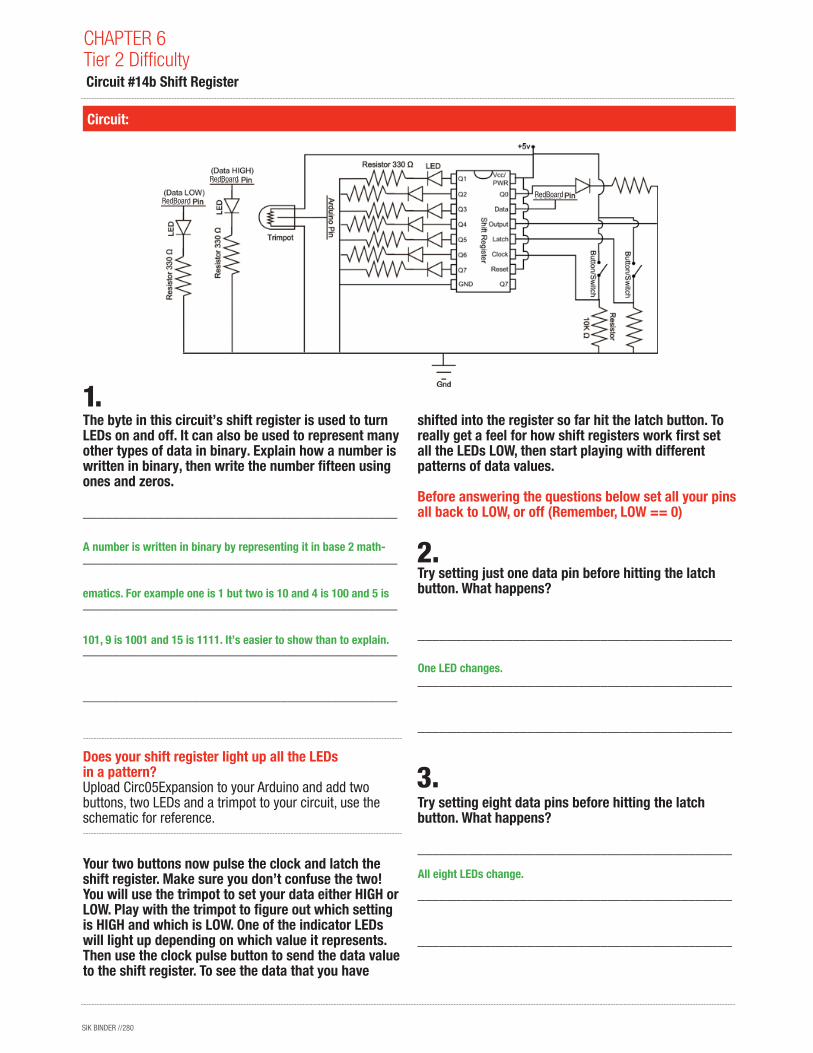
SIK BINDER //280
The byte in this circuit’s shift register is used to turn LEDs on and off. It can also be used to represent many other types of data in binary. Explain how a number is written in binary, then write the number fifteen using ones and zeros.
___________________________________________
___________________________________________
___________________________________________
___________________________________________
___________________________________________
Does your shift register light up all the LEDs in a pattern? Upload Circ05Expansion to your Arduino and add two buttons, two LEDs and a trimpot to your circuit, use the schematic for reference.
Your two buttons now pulse the clock and latch the shift register. Make sure you don’t confuse the two! You will use the trimpot to set your data either HIGH or LOW. Play with the trimpot to figure out which setting is HIGH and which is LOW. One of the indicator LEDs will light up depending on which value it represents. Then use the clock pulse button to send the data value to the shift register. To see the data that you have
shifted into the register so far hit the latch button. To really get a feel for how shift registers work first set all the LEDs LOW, then start playing with different patterns of data values.
Before answering the questions below set all your pins all back to LOW, or off (Remember, LOW == 0)
Try setting just one data pin before hitting the latch button. What happens?
___________________________________________
___________________________________________
___________________________________________
Try setting eight data pins before hitting the latch button. What happens?
___________________________________________
___________________________________________
___________________________________________
Circuit:
CHAPTER 6Tier 2 Difficulty Circuit #14b Shift Register
A number is written in binary by representing it in base 2 math-
ematics. For example one is 1 but two is 10 and 4 is 100 and 5 is
101, 9 is 1001 and 15 is 1111. It’s easier to show than to explain.
One LED changes.
All eight LEDs change.
RedBoard
RedBoard
RedBoard
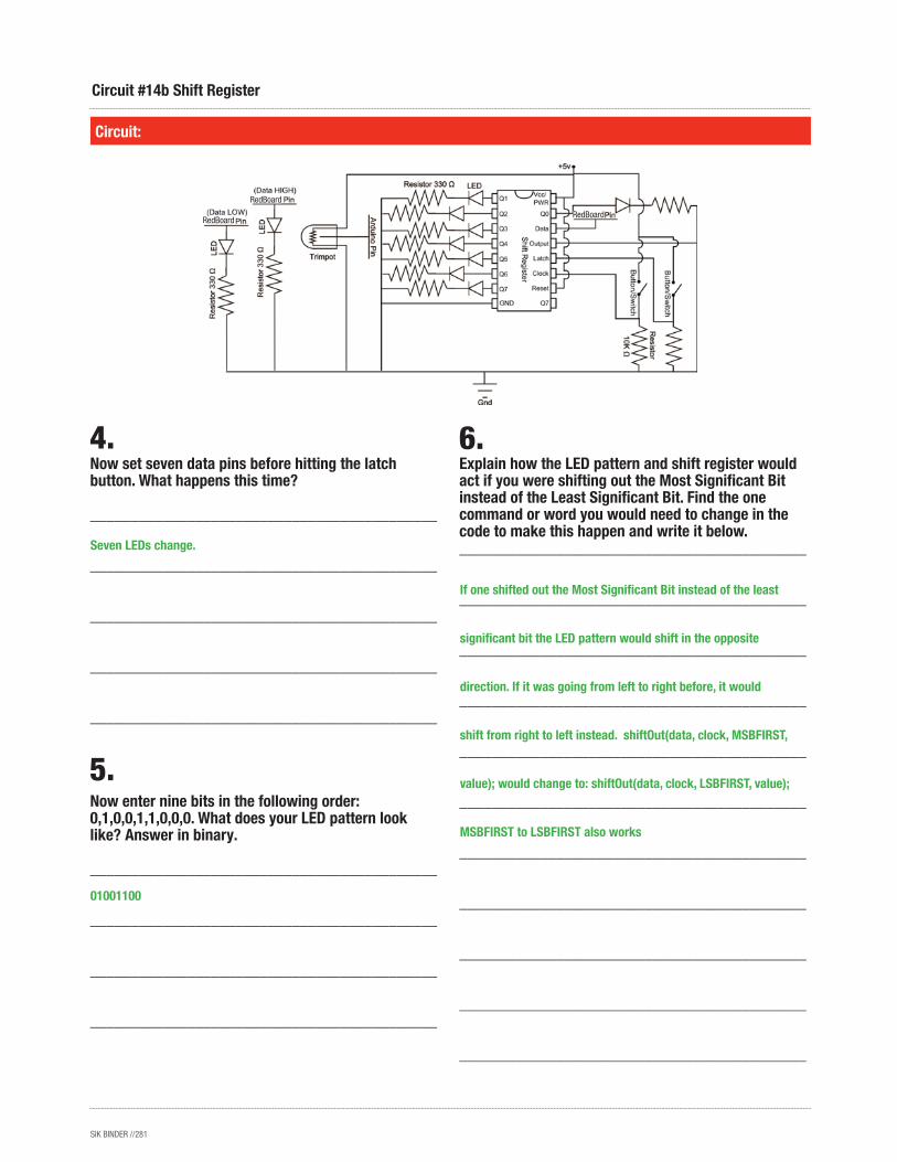
SIK BINDER //281
Now set seven data pins before hitting the latch button. What happens this time?
___________________________________________
___________________________________________
___________________________________________
___________________________________________
___________________________________________
Now enter nine bits in the following order: 0,1,0,0,1,1,0,0,0. What does your LED pattern look like? Answer in binary.
___________________________________________
___________________________________________
___________________________________________
___________________________________________
Explain how the LED pattern and shift register would act if you were shifting out the Most Significant Bit instead of the Least Significant Bit. Find the one command or word you would need to change in the code to make this happen and write it below. ___________________________________________
___________________________________________
___________________________________________
___________________________________________
___________________________________________
___________________________________________
___________________________________________
___________________________________________
___________________________________________
___________________________________________
___________________________________________
Circuit:
Circuit #14b Shift Register
01001100
If one shifted out the Most Significant Bit instead of the least
significant bit the LED pattern would shift in the opposite
direction. If it was going from left to right before, it would
shift from right to left instead. shiftOut(data, clock, MSBFIRST,
value); would change to: shiftOut(data, clock, LSBFIRST, value);
MSBFIRST to LSBFIRST also works
Seven LEDs change.
RedBoard
RedBoard
RedBoard
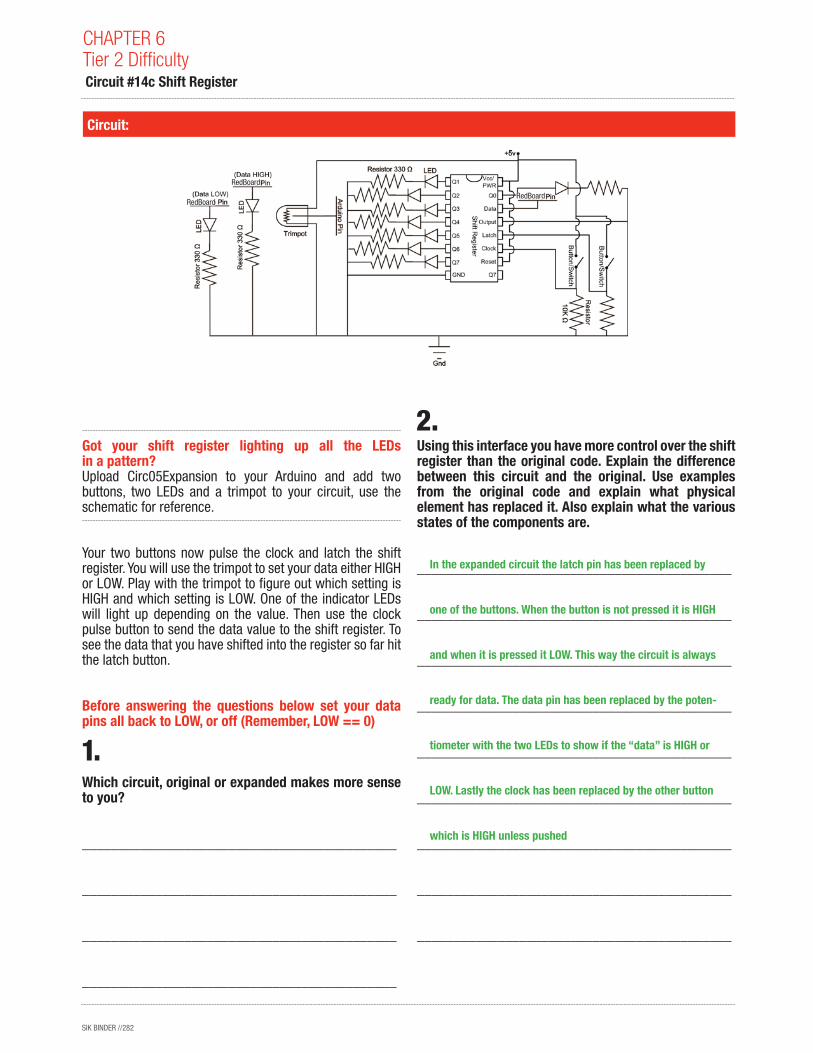
SIK BINDER //282
Got your shift register lighting up all the LEDs in a pattern? Upload Circ05Expansion to your Arduino and add two buttons, two LEDs and a trimpot to your circuit, use the schematic for reference.
Your two buttons now pulse the clock and latch the shift register. You will use the trimpot to set your data either HIGH or LOW. Play with the trimpot to figure out which setting is HIGH and which setting is LOW. One of the indicator LEDs will light up depending on the value. Then use the clock pulse button to send the data value to the shift register. To see the data that you have shifted into the register so far hit the latch button.
Before answering the questions below set your data pins all back to LOW, or off (Remember, LOW == 0)
Which circuit, original or expanded makes more sense to you?
___________________________________________
___________________________________________
___________________________________________
___________________________________________
Using this interface you have more control over the shift register than the original code. Explain the difference between this circuit and the original. Use examples from the original code and explain what physical element has replaced it. Also explain what the various states of the components are.
___________________________________________
___________________________________________
___________________________________________
___________________________________________
___________________________________________
___________________________________________
___________________________________________
___________________________________________
___________________________________________
Circuit:
CHAPTER 6Tier 2 Difficulty Circuit #14c Shift Register
In the expanded circuit the latch pin has been replaced by
one of the buttons. When the button is not pressed it is HIGH
and when it is pressed it LOW. This way the circuit is always
ready for data. The data pin has been replaced by the poten-
tiometer with the two LEDs to show if the “data” is HIGH or
LOW. Lastly the clock has been replaced by the other button
which is HIGH unless pushed
RedBoard
RedBoard
RedBoard
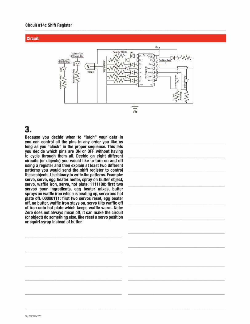
SIK BINDER //283
Circuit:
Circuit #14c Shift Register
Because you decide when to “latch” your data in you can control all the pins in any order you like as long as you “clock” in the proper sequence. This lets you decide which pins are ON or OFF without having to cycle through them all. Decide on eight different circuits (or objects) you would like to turn on and off using a register and then explain at least two different patterns you would send the shift register to control these objects. Use binary to write the patterns. Example: servo, servo, egg beater motor, spray on butter object, servo, waffle iron, servo, hot plate. 1111100: first two servos pour ingredients, egg beater mixes, butter sprays on waffle iron which is heating up, servo and hot plate off. 00000111: first two servos reset, egg beater off, no butter, waffle iron stays on, servo tilts waffle off of iron onto hot plate which keeps waffle warm. Note: Zero does not always mean off, it can make the circuit (or object) do something else, like reset a servo position or squirt syrup instead of butter.
___________________________________________
___________________________________________
___________________________________________
___________________________________________
___________________________________________
___________________________________________
___________________________________________
___________________________________________
___________________________________________
___________________________________________
___________________________________________
___________________________________________
___________________________________________
___________________________________________
___________________________________________
___________________________________________
RedBoard
RedBoard
RedBoard

SIK BINDER //284
Soft potentiometers come in a bunch of shapes and sizes. Explain how you could combine two soft potentiometers, two servos and a slingshot to create a machine that launches marshmallows (because they are soft) towards wherever the two soft potentiometers tell it to, include a schematic or logic flow chart in the blank section .... or just go build one instead of explaining how it might work. You’ve finished the SIK, what are you waiting for? In fact, forget these guiding questions, if you want just use this page to brainstorm what your next project will be.
CHAPTER 6Tier 2 Difficulty Circuit #10 Soft Potentiometers
Name:Date:

SIK BINDER //285
Circuit #10 Soft Potentiometers

SIK BINDER //286
We know by now that PWM is represented in Arduino language as a value somewhere between 0 and 255. We also know that the PWM signal is just the RedBoard turning the PWM pin ON, or HIGH, then LOW, or OFF, a bunch of times really, really fast. The thing is the computer can turn the signal HIGH and LOW a lot faster than a human can follow. So what does the PWM signal look like to us and how can we measure it? Good question. Upload the PWM Expansion Code to your Arduino, attach PWM pin # 9 to ground on your breadboard and measure the voltage between the two wires. Switch values and reload the code as necessary to fill in the table below.
What is the equation you use to convert the percentage to PWM values and back again?
_________________________________________________________________________________________
_________________________________________________________________________________________
_________________________________________________________________________________________
_________________________________________________________________________________________
Why does the PWM value only go up to 255 if it represents 256 different values?
_________________________________________________________________________________________
_________________________________________________________________________________________
Often you will use analog sensors with your digital microprocessor. These analog sensors are even more difficult than the PWM signal. They talk to the microprocessor in 1024 little pieces!
What is the equation you use to convert the percentage to analog values and back again?
_________________________________________________________________________________________
_________________________________________________________________________________________
Fill in the table below:
Fill in the table below:
CHAPTER 6Tier 2 Difficulty PWM
Name:Date:
25.5 51.0 76.5 102.0 152.5 178.5 204.0 229.5
(%val * 255) = PWM value
Map(%val, 0, 100, 0 , 255)= convertedValue (variable name) convertedValue may differ
(%val * 1023) = analog value
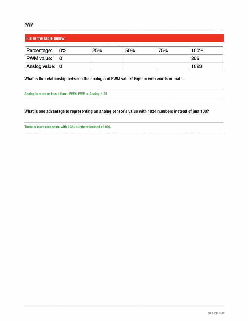
SIK BINDER //287
Fill in the table below:
What is the relationship between the analog and PWM value? Explain with words or math.
_________________________________________________________________________________________
_________________________________________________________________________________________
What is one advantage to representing an analog sensor’s value with 1024 numbers instead of just 100?
_________________________________________________________________________________________
_________________________________________________________________________________________
PWM
Analog is more or less 4 times PWM. PWM ≈ Analog * .25
There is more resolution with 1024 numbers instead of 100.
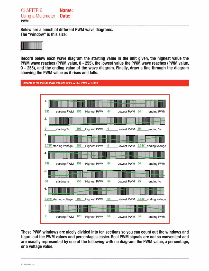
SIK BINDER //288
CHAPTER 6Using a Multimeter
Name:Date:
Below are a bunch of different PWM wave diagrams. The “window” is this size:
Record below each wave diagram the starting value in the unit given, the highest value the PWM wave reaches (PWM value, 0 - 255), the lowest value the PWM wave reaches (PWM value, 0 - 255), and the ending value of the wave diagram. Finally, draw a line through the diagram showing the PWM value as it rises and falls.
These PWM windows are nicely divided into ten sections so you can count out the windows and figure out the PWM values and percentages easier. Real PWM signals are not so convenient and are usually represented by one of the following with no diagram: the PWM value, a percentage, or a voltage value.
Remember for the SIK PWM values: 100% = 255 PWM = 1.8mV
PWM
1. _______starting PWM
______Highest PWM
_______Lowest PWM
_______ending PWM
2. _______starting %
______Highest PWM
_______Lowest PWM
_______ending %
3. _____starting voltage
______Highest PWM
_______Lowest PWM
______ending voltage
4. _______starting PWM
______Highest PWM
_______Lowest PWM
_______ending PWM
5. _______starting %
______Highest PWM
_______Lowest PWM
_______ending %
6. _____starting voltage
______Highest PWM
_______Lowest PWM
______ending voltage
7. _______starting PWM
______Highest PWM
_______Lowest PWM
_______ending PWM
0
1.26V
50
192
3.78V
0
255
128
192
255
192
255
192
255
64
64
64
64
0
0
64
64
2.53V
25
64
5.05V
75
64
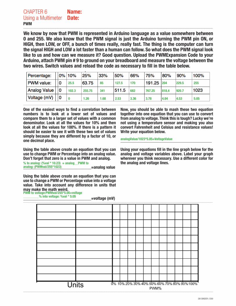
SIK BINDER //289
CHAPTER 6Using a Multimeter
Name:Date:
PWM
We know by now that PWM is represented in Arduino language as a value somewhere between 0 and 255. We also know that the PWM signal is just the Arduino turning the PWM pin ON, or HIGH, then LOW, or OFF, a bunch of times really, really fast. The thing is the computer can turn the signal HIGH and LOW a lot faster than a human can follow. So what does the PWM signal look like to us and how can we measure it? Good question. Upload the PWMExpansion Code to your Arduino, attach PWM pin # 9 to ground on your breadboard and measure the voltage between the two wires. Switch values and reload the code as necessary to fill in the table below.
One of the easiest ways to find a correlation between numbers is to look at a lower set of values and compare them to a larger set of values with a common denominator. Look at all the values for 10% and then look at all the values for 100%. If there is a pattern it should be easier to see it with these two set of values simply because they are different by a factor of 10, or one decimal place.
Using the table above create an equation that you can use to change PWM or Percentage into an analog value. Don’t forget that zero is a value in PWM and analog.
________________________________=analog value
Using the table above create an equation that you can use to change a PWM or Percentage value into a voltage value. Take into account any difference in units that may make the math weird.
________________________________=voltage (mV)
Now, you should be able to mash these two equation together into one equation that you can use to convert from analog to voltage. Think this is tough? Lucky we’re not using a temperature sensor and making you also convert Fahrenheit and Celsius and resistance values! Write your equation below.
___________________________________________
Using your equations fill in the line graph below for the analog and voltage variables above. Label your graph wherever you think necessary. Use a different color for the analog and voltage lines.
25.5 85 127.5 170 204 229.5 255
102.3 255.75 341 682 767.25 818.4 920.7
0 1.26 1.68 2.53 3.36 3.78 4.04 4.53 5.05
% to analog: (%val * 10.23) = analog__PWM to analog: (PWMval/255*1023)
PWM to voltage:PWMval/255*5.05=voltage _________% into voltage: %val * 5.05
analogValue/1023*5.05=VoltageValue
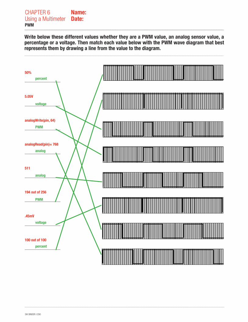
SIK BINDER //290
percent
voltage
PWM
analog
analog
PWM
voltage
percent
50%
_________________________________________
5.05V
_________________________________________
analogWrite(pin, 64)
_________________________________________
analogRead(pin)= 768
_________________________________________
511
_________________________________________
194 out of 256
_________________________________________
.45mV
_________________________________________
100 out of 100
_________________________________________
Write below these different values whether they are a PWM value, an analog sensor value, a percentage or a voltage. Then match each value below with the PWM wave diagram that best represents them by drawing a line from the value to the diagram.
CHAPTER 6Using a Multimeter
Name:Date:
PWM