sik binder //11 - valley central high school · sik binder //15 // series series parallel //...
TRANSCRIPT

SIK BINDER //11
SIK BINDER //12
2Electrical

SIK BINDER //13
Electrical
SIK BINDER //14
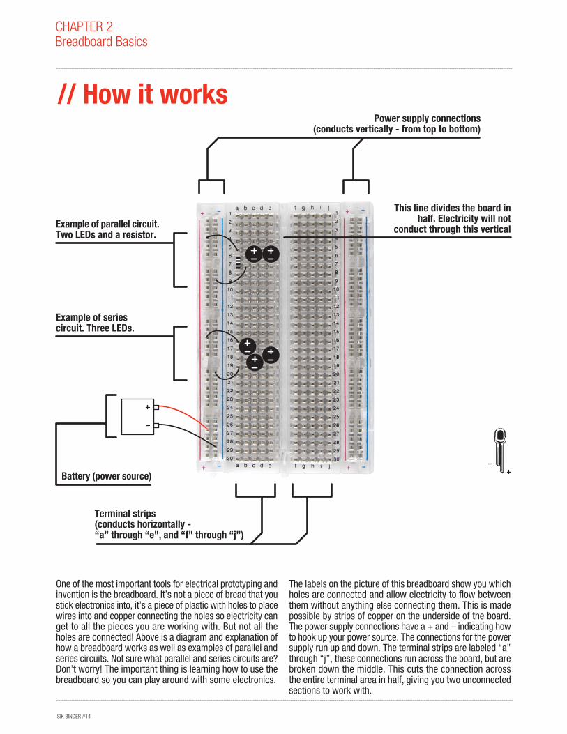
Example of parallel circuit.Two LEDs and a resistor.
Example of series circuit. Three LEDs.
Battery (power source)
Terminal strips(conducts horizontally -“a” through “e”, and “f” through “j”)
Power supply connections(conducts vertically - from top to bottom)
This line divides the board in half. Electricity will not
conduct through this vertical
CHAPTER 2Breadboard Basics
// How it works
One of the most important tools for electrical prototyping and invention is the breadboard. It’s not a piece of bread that you stick electronics into, it’s a piece of plastic with holes to place wires into and copper connecting the holes so electricity can get to all the pieces you are working with. But not all the holes are connected! Above is a diagram and explanation of how a breadboard works as well as examples of parallel and series circuits. Not sure what parallel and series circuits are? Don’t worry! The important thing is learning how to use the breadboard so you can play around with some electronics.
The labels on the picture of this breadboard show you which holes are connected and allow electricity to flow between them without anything else connecting them. This is made possible by strips of copper on the underside of the board. The power supply connections have a + and – indicating how to hook up your power source. The connections for the power supply run up and down. The terminal strips are labeled “a” through “j”, these connections run across the board, but are broken down the middle. This cuts the connection across the entire terminal area in half, giving you two unconnected sections to work with.

SIK BINDER //15
// SeriesSeries
// Parallel Parallel
Because the copper plating below the power supply connections and the terminal connections conduct electricity there are many different ways to hook up the same circuit and make it work. All that matters is that the electricity can flow through the entire circuit from power (+) to ground (-).
This is an example of the same two circuits from the previous page hooked up in different ways that still work the same. There are many differences between this picture and the previous one. First of all, at the very top there is a wire connecting the positive (+) power terminal on the left with the positive (+) power terminal on the right. Now it is possible to supply power to your circuits from either side of the board. That’s why this example of a parallel circuit has a red wire stretching all the way to the positive (+) power terminal on the right side. What would you do if you wanted to use the ground (-) power terminal on the right side of the board?
Another thing that has changed in the parallel circuit example is the position of the resistor. In the previous image, the resistor went from the row with the negative LED connections to the row below with a wire connecting that f inal row to the ground (-) power terminal. This is an example of tossing out a wire because you can use the wires coming out of components to plug directly into the power terminals. You can do the same thing with your LEDs if you like, try it out.
Lastly, the positions of the LEDs have changed in both examples. This is because it doesn’t matter where the LEDs are positioned to the left or right (columns “a” through “e”), as long as they are plugged into the correct rows (up and down).
CHAPTER 2Breadboard
Name:Date:

SIK BINDER //16
Here are some quick questions to make sure you understand the breadboard:1. Circle the power terminals below, make sure you get all of them.
2. Draw wires to complete six LED circuits that will work. Each circuit needs either a total of three LEDs or two LEDs and a resistor. Use all power terminals at least once and don’t forget to hook up your battery.
3. Inside the dotted lines draw lines to show where electricity will conduct without plugging anything else in.
CHAPTER 2Breadboard
Name:Date:
SIK BINDER //17
CHAPTER 2Analog and Digital
Name:Date:
All of the electrical signals that the RedBoard works with are either Analog or Digital. It is extremely important to understand the difference between these two types of signal and how to manipulate the information these signals represent.
// Analog A continuous stream of information with values between and including 0% and 100%.
Humans perceive the world in analog. Everything we see and hear is a continuous transmission of information to our senses. The temperatures we perceive are never 100% hot or 100% cold, they are constantly changing between our ranges of acceptable temperatures. This continuous stream is what defines analog data. Digital information, the complementary concept to Analog, estimates analog data using only ones and zeros.
In the world of Arduino an analog signal is simply a signal that can be HIGH (on), LOW (off) or anything in between these two states. This means an Analog signal has a voltage value that can be anything between 0V and 5V (unless you mess with the Analog Reference pin). Analog allows you to send output or receive input about devices that run at percentages as well as on and off. The RedBoard does this by sampling the voltage signal sent to these pins and comparing it to a voltage reference signal (5V). Depending on the voltage of the Analog signal when compared to the Analog Reference signal the RedBoard then assigns a numerical value to the signal somewhere between 0 (0%) and 1023 (100%). The digital system of the RedBoard can then use this number in calculations and sketches.
To receive Analog Input the Arduino uses Analog pins # 0 - # 5. These pins are designed for use with components that output Analog information and can be used for Analog
Input. There is no setup necessary and to read them use the command: analogRead(pinNumber);where pinNumber is the Analog In pin to which the the Analog component is connected. The analogRead command will return a number including or between 0 and 1023.
The RedBoard also has the capability to output a digital signal that acts as an Analog signal, this signal is called Pulse Width Modulation (PWM). Digital Pins # 3, # 5, # 6, # 9, # 10 and #11 have PWM capabilities. To output a PWM signal use the command: analogWrite(pinNumber, value); where pinNumber is a Digital Pin with PWM capabilities and value is a number between 0 (0%) and 255 (100%). On the Arduino UNO PWM pins are signified by a ~ sign. For more information on PWM see the PWM worksheets or S.I.K. circuit 12.
Examples of Analog:
Values: Temperature, volume level, speed, time, light, tide level, the list goes on....Sensors: Temperature sensor, Photoresistor, Microphone, Turntable, Speedometer, etc....
Things to Remember about Analog:
Analog Input uses the Analog In pins, Analog Output uses the PWM pinsTo receive an Analog signal use: analogRead(pinNumber); To be able to send a PWM signal use: analogWrite(pinNumber, value); Analog Input values range from 0 to 1023 (1024 values because it uses 10 bits, 210)PWM Output values range from 0 to 255 (256 values because it uses 8 bits, 28)
Analog
SIK BINDER //18
CHAPTER 2Analog and Digital
Name:Date:
All of the electrical signals that the RedBoard works with are either Analog or Digital. It is extremely important to understand the difference between these two types of signal and how to manipulate the information these signals represent.
// Digital An electronic signal transmitted as binary code that can be either the presence or absence of current, high and low voltages or short pulses at a particular frequency.
Humans perceive the world in analog, but robots, computers and circuits use Digital. A digital signal is a signal that has only two states. These states can vary depending on the signal, but simply defined the states are ON or OFF, never in between.
Digital signals are used for everything with the exception of Analog Input. Depending on the voltage of the Arduino the ON or HIGH of the Digital signal will be equal to the system voltage, while the OFF or LOW signal will always equal 0V. This is a fancy way of saying that on a 5V RedBoard the HIGH signals will be a little under 5V and on a 3.3V RedBoard the HIGH signals will be a little under 3.3V.
To receive or send Digital signals the Arduino uses Digital pins # 0 - # 13. You may also setup your Analog In pins to act as Digital pins. To set up Analog In pins as Digital pins use the command: pinMode(pinNumber, value); where pinNumber is an Analog pin (A0 – A5) and value is either INPUT or OUTPUT. To setup Digital pins use the same command but reference a Digital pin for pinNumber instead of an Analog In pin. Digital pins default as input, so really you only need to set them to OUTPUT in pinMode. To read these pins use the command:
digitalRead(pinNumber); where pinNumber is the Digital pin to which the Digital component is connected. The digitalRead command will return either a HIGH or a LOW signal. To send a Digital signal to a pin use the command: digitalWrite(pinNumber, value); where pinNumber is the number of the pin sending the signal and value is either HIGH or LOW.
The RedBoard also has the capability to output a Digital signal that acts as an Analog signal, this signal is called Pulse Width Modulation (PWM). Digital Pins # 3, # 5, # 6, # 9, # 10 and #11 have PWM capabilities. To output a PWM signal use the command: analogWrite(pinNumber, value); where pinNumber is a Digital Pin with PWM capabilities and value is a number between 0 (0%) and 255 (100%). For more information on PWM see the PWM worksheets or S.I.K. circuit 12.
Examples of Digital:
Values: On/Off, Men’s room/Women’s room, pregnancy, consciousness, the list goes on....Sensors/Interfaces: Buttons, Switches, Relays, CDs, etc....
Things to Remember about Digital:
Digital Input/Output uses the Digital pins, but Analog In pins can be used as DigitalTo receive a Digital signal use: digitalRead(pinNumber); To be able to send a Digital signal use: digitalWrite(pinNumber, value); Digital Input and Output are always either HIGH or LOW / ON or OFF.
Digital
SIK BINDER //19
CHAPTER 2Analog and Digital
Name:Date:
All of the electrical signals that the RedBoard works with are either input or output. It is extremely important to understand the difference between these two types of signal and how to manipulate the information these signals represent.
// Input SignalsA signal entering an electrical system, in this case a micro-controller. Input to the RedBoard pins can come in one of two forms; Analog Input or Digital Input. Analog Input enters your RedBoard through the Analog In pins # 0 - # 5. These signals originate from analog sensors and interface devices. These analog sensors and devices use voltage levels to communicate their information instead of a simple yes (HIGH) or no (LOW). For this reason you cannot use a digital pin as an input pin for these devices. Analog Input pins are used only for receiving Analog signals. It is only possible to read the Analog Input pins so there is no command necessary in the setup( ) function to prepare these pins for input. To read the Analog Input pins use the command: analogRead(pinNumber); where pinNumber is the Analog Input pin number. This function will return an Analog Input reading between 0 and 1023. A reading of zero corresponds to 0 Volts and a reading of 1023 corresponds to 5 Volts. These voltage values are emitted by the analog sensors and interfaces. If you have an Analog Input that could exceed Vcc + .5V you may change the voltage that 1023 corresponds to by using the Aref pin. This pin sets the maximum voltage parameter your Analog Input pins can read. The Aref pin's preset value is 5V.
Digital Input can enter your RedBoard through any of the Digital Pins # 0 - # 13. Digital Input signals are either HIGH (On, 5V) or LOW (Off, 0V). Because the Digital pins can be
used either as input or output you will need to prepare the RedBoard to use these pins as inputs in your setup( )function. To do this type the command: pinMode(pinNumber, INPUT); inside the curly brackets of the setup( ) function where pinNumber is the Digital pin number you wish to declare as an input. You can change the pinMode in the loop( )function if you need to switch a pin back and forth between input and output, but it is usually set in the setup( )function and left untouched in the loop( )function. To read the Digital pins set as inputs use the command: digitalRead(pinNumber); where pinNumber is the Digital Input pin number.
Input can come from many different devices, but each device's signal will be either Analog or Digital, it is up to the user to figure out which kind of input is needed. Hook up the hardware and then type the correct code to properly use these signals.
Things to Remember about Input:
Input is either Analog or Digital, make sure to use the correct pins depending on type.To take an Input reading use analogRead(pinNumber); (for analog)Or digitalRead(pinNumber); (for digital)Digital Input needs a pinMode command such as pinMode(pinNumber, INPUT);Analog Input varies from 0 to 1023Digital Input is always either HIGH or LOW
Examples of Input:
Push Buttons, Potentiometers, Photoresistors, Flex Sensors
Input
SIK BINDER //20
CHAPTER 2Analog and Digital
Name:Date:
All of the electrical signals that the Arduino works with are either input or output. It is extremely important to understand the difference between these two types of signal and how to manipulate the information these signals represent.
// Output Signals A signal exiting an electrical system, in this case a micro-controller.
Output to the RedBoard pins is always Digital, however there are two different types of Digital Output; regular Digital Output and Pulse Width Modulation Output (PWM). Output is only possible with Digital pins # 0 - # 13. The Digital pins are preset as Output pins, so unless the pin was used as an Input in the same sketch, there is no reason to use the pinMode command to set the pin as an Output. Should a situation arise where it is necessary to reset a Digital pin to Output from Input use the command: pinMode(pinNumber, OUTPUT); where pinNumber is the Digital pin number set as Output. To send a Digital Output signal use the command: digitalWrite(pinNumber, value); where pinNumber is the Digital pin that is outputting the signal and value is the signal. When outputting a Digital signal value can be either HIGH (On) or LOW (Off).
Digital Pins # 3, # 5, # 6, # 9, # 10 and #11 have PWM capabilities. This means you can Output the Digital equivalent of an Analog signal using these pins. To Output a PWM signal use the command: analogWrite(pinNumber, value); where pinNumber is a Digital Pin with PWM capabilities and
value is a number between 0 (0%) and 255 (100%). For more information on PWM see the PWM worksheets or S.I.K. circuit 12.
Output can be sent to many different devices, but it is up to the user to figure out which kind of Output signal is needed, hook up the hardware and then type the correct code to properly use these signals.
Things to remember about Output:
Output is always DigitalThere are two kinds of Output: regular Digital or PWM (Pulse Width Modulation)To be able to send an Output signal use: analogWrite(pinNumber, value); (for analog) or digitalWrite(pinNumber, value); (for digital)Output pin mode is set using the pinMode command: pinMode(pinNumber, OUTPUT);Regular Digital Output is always either HIGH or LOWPWM Output varies from 0 to 255
Examples of Output:
Light Emitting Diodes (LED's), Piezoelectric Speakers, Servo Motors
Output

SIK BINDER //21
CHAPTER 2Programming Concepts, Input/Output Activity
Purpose: Group activity teaching the concepts of input and output as used in Arduino Programming and Physical Computing. Text formatted like this denotes actual Arduino code.
Materials: Three to five different sized balls and a white/chalk board big enough so the whole room can see it.
Vocabulary to be explained prior to activity:
input: A pin mode that intakes information.output: A pin mode that sends information.digitalRead: Command used to get a HIGH or LOW value from a digital input pin.analogRead: Command used to get a value between or including 0 and 1023 from an analog input pin.digitalWrite: Command used to send a HIGH or LOW value to an output pin.analogWrite: Command used to send a PWM value to an output pin simulating an analog output.PWM: A value between 0 and 255 representing a digital signal simulating an analog output. Used with analogWrite.HIGH: Electrical signal present (5V for Uno). Also ON or True in boolean logic.LOW: No electrical signal present (0V). Also OFF or False in boolean logic.
Preparation: Divide the class in quarters, assign each group the following names: Sensors, Input Pins, Output Pins, and Output Components. Arrange the groups in lines in this order about ten to twenty feet apart (or farther if the students are older). The students at the front of each line are Code, their job is to write the Arduino code corresponding to the signal received by their team on the chalk board or white board. Distribute the balls so that each student in the Sensor line has at least one of each size. The smallest balls (tennis or bouncy balls) represent the smallest signal a sensor can send to the RedBoard, LOW. The largest balls represent the largest signal a sensor can send, HIGH. The ball or balls of medium size represent PWM values depending on size.
Activity: To start the activity ask the Code student in the Sensor line to tell the class what kind of sensors the Sensor line represents (photoresistor, potentiometer, flex sensor, etc...) and write on the board what the sensor value is. The sensor value corresponds to the sensor type. For example, if the sensor type is photoresistor then “sunny day” might be written to signal a HIGH signal or “really cloudy” might be written to signal a smaller PWM value.
Each student in the Sensor line then throws the corresponding sized ball to a student in the Input Pin line. Once all the Input Pins have caught their “signals” the Code student in the Input Pin line writes the analogRead or digitalRead value they think corresponds to the signal.
Once the analogRead value has been written on the board the Input Pin line throws the balls to the Output Pin line. The Code student in that line writes the analogWrite or digitalWrite value they think corresponds to the signal on the board and the balls are thrown to the Output Components.
Once all the Output Components catch their balls the Code student tells the class what type of output component the Output Component line represents and the Output Components strike a pose depending on the signal they received. In the example below poses for LEDs and Servos are shown, but students should be encouraged to make up their own output poses or actions. For example, to represent a HIGH value with motor component outputs students might run in place as fast as they can.
Once the Output Component line has finished, the balls are thrown back to the Sensor line, the Code students are replaced by another student in their line and the process starts over. Once every student has had a chance to be the Code student the lines should switch so eventually everyone has a chance to play each part of the input/output process.
This version of the input/output activity is the simplest form of the activity. If students are comfortable with this version and want more of a challenge there are many ways to complicate the activity.
Give the Output line a set of balls as well as the Sensor line and place a piece of code between the Input and Output lines. The code should be a map command switching the Output signal. For example use: map(signal, 0, 1023, 255, 0); so that the Output line must throw a large ball (HIGH signal) when the Input line receives a small ball (LOW signal). You can then switch this code through out the game.
Get rid of the Code students and have the Sensor line choose which ball they will throw. Each student can yell out what their line's value equals depending on the size of the ball they catch. This version is a little more fun but will also be a little more chaotic.

SIK BINDER //22
Once all the Output Components catch their balls the Code student tells the class what type of output component the Output Component line represents and the Output Components strike a pose depending on the signal they received. In the example below poses for LEDs and Servos are shown, but students should be encouraged to make up their own output poses or actions. For example, to represent a HIGH value with motor component outputs students might run in place as fast as they can.
Once the Output Component line has finished, the balls are thrown back to the Sensor line, the Code students are replaced by another student in their line and the process starts over. Once every student has had a chance to be the Code student the lines should switch so eventually everyone has a chance to play each part of the input/output process.
This version of the input/output activity is the simplest form of the activity. If students are comfortable with this version and want more of a challenge there are many ways to complicate the activity.
Give the Output line a set of balls as well as the Sensor line and place a piece of code between the Input and Output lines. The code should be a map command switching the Output signal. For example use:
map(signal, 0, 1023, 255, 0); so that the Output line must throw a large ball (HIGH signal) when the Input line receives a small ball (LOW signal). You can then switch this code through out the game.
Get rid of the Code students and have the Sensor line choose which ball they will throw. Each student can yell out what their line's value equals depending on the size of the ball they catch. This version is a little more fun but will also be a little more chaotic.
CHAPTER 2Programming Concepts, Input/Output Activity
Activity}
Code
Sensors Input Pins Output Pins Output Components
SMALL
MEDIUM-SMALL
MEDIUM
MEDIUM-LARGE
LARGE
// LOW
// HIGH
// PWM VALUE 1
// PWM VALUE 2
// PWM VALUE 3
Additional thoughts: This is a great activity just prior to computer lab time. Instead of having kids bouncing off the monitors they will be calmer and ready to sit still applying the
concepts they just solidified through physical activity. This is great for kinesthetic learners in particular.

SIK BINDER //23
For the most part in computer language one means ON and zero means OFF. This keeps things nice and simple, but what if you want to turn something halfway ON so that it is not all the way ON and not all the way OFF? You can't just use a decimal because digital technology only understands ones and zeros. For this reason some of the pins on your Arduino are labeled PWM or Pulse Width Modulation pins. This means you can send a bunch of ones and zeros real quick and the Arduino board will read these ones and zeros as an average somewhere between one and zero. The red line in the diagrams represent the average. See tables to the right.
Luckily a lot of the work has been done for you so you don't have to figure out the actual patterns of ones and zeros. All you have to do is pick a number between 0 and 255 and type the command analogWrite. The number zero means the pin is set fully off, the number 255 means the pin is set fully on, and all other numbers set the pin to values between ON (100% or 255) and OFF (0% or 0). You can use PWM on any pin labeled PWM and do not need to set the pin mode before sending an analogWrite command.
How do you think a PWM signal will affect each of these components compared to a 1 or a 0?
LED:
Motor:
Piezo:
CHAPTER 2PWM
Name:Date:
Draw a line through these two charts to show where you believe the PWM value should be.
There are many concepts outside of electrical engineering that are similar to Pulse Width Modulation. Can you list at least three and explain what is being modulated?
PWM signal at 25% PWM signal at 50%
PWM signal rising from 25% - 75%PWM signal at 75%

SIK BINDER //24
Below are five different PWM windows. A PWM signal is simply a bunch of PWM windows one after another. Some are missing labels and some are missing diagrams. Please fill in the blanks on the middle three.
Below are three different metaphors for a PWM window and a PWM signal. Write the physical item that represents the window and the item or items that represents the signal. Then estimate the PWM percent.
GG G
High (ON)Low (OFF)
PWM percent 0%(No wave)
PWM percentage PWM percent 50%(Draw in window)
PWM percent 75%(Draw in window)
PWM percent 100%(No wave)
Window:
Signal percentage: Signal percentage: Signal percentage:
Window: Window:
CHAPTER 2PWM
Name:Date:
Computers and microprocessors only understand two things, ON and OFF. These are represented in a few different ways. There is ON and OFF, One and Zero, or HIGH and LOW. Ones and Zeros are used in the computer language Binary, HIGH and LOW are used with electricity, ON and OFF are plain old human speak.
But what if we want to turn something digital less than 100% ON? Then we use something called PWM, or Pulse Width Modulation. The way your Arduino microprocessor does this is by turning the electricity on a PWM pin ON and then OFF very quickly. The longer the electricity is ON the closer the PWM value is to 100%. This is very useful for controlling a bunch of stuff. For example: the brightness of a light bulb, volume of sound, or the speed of a motor. These are very basic examples, what else might you need to control that is not only ON or OFF? Explain at least two examples.
A microprocessor creates a PWM signal by using a built in clock. The microprocessor measures a certain amount of time (also called a window or a period) and turns the PWM pin ON (or HIGH) for the first part of this window and then OFF (or LOW) near the end of the window. The window is filled up with a different length ON (or HIGH) signal depending on the PWM value. If the PWM value is 50% then the PWM signal is ON (or HIGH) for half of the window. If the PWM value is 25% then the PWM signal is ON (or HIGH) for a quarter of the window. The only time the window will not have a LOW value is if the PWM signal is turned completely ON the whole time and therefore equal to 100% ON. The opposite is true as well, if the PWM signal is set to 0% or OFF, then there will not be any HIGH value at the beginning of the window. Explain in your own words what a PWM window is.