siemens hrc fuse type 3na3
DESCRIPTION
SIEMENS HRC Fuse Type 3NA3TRANSCRIPT


Contents
Technical description ............................................................................................................... 1
Selection & Ordering Data* ..................................................................................................... 6
Characteristic Curves .............................................................................................................. 11
Dimensions* ......................................................................................................................... 15
* Include Accessories - Fuse Base, Fuse Puller & Isolating Link

1
LV HRC Fuses
Technical descriptionLow-Voltage fuses
3NA3 LV HRC fuses are available in 5 different sizes from 2 to 630 A.
The main part of the LV HRC fuses is the fuse-element of high-grade copper. Theimportant factors are the resistance value per meter, the material thickness and thedimensional accuracy. Three criteria decisive in the production of the fuse-elementsare:
• Accurate cutting and punching
• Precise application of the solder deposit
• Accurate and concentric insertion of the fuse-element in the fuse body.
Where several fuse-elements are involved, these are fitted exactly parallel to eachother in the fuse body. This ensures adequate cooling of the individual arcs. Theprecision of the parallel arrangement can be verified by observing the beads ofmolten metal after the fuse has switched off a short circuit. The fuse-element mustnot be too close to the wall of the fuse body as otherwise there is no protectivelayer of sand. If the arc were to touch the wall of the fuse body, the fuse mightburst or blow.
The fuse-elements of 3NA3 fuses are of operating class gG and of copper. The useof silver-plated or pure silver fuse-elements is not required for physical reasons.
Oxidation, also called scaling of copper, which reduces the cross-section of thefuse-element, occurs only at a temperature of approx. 350 0C. In the time/currentrange within which a fuse operates, however, only temperatures of 1800C to 2400Care attained. Hence safe tripping is ensured with this fuse element.
Short data description3NA3 LV HRC Fuses
Standards IS 13703 Part 2 Section 1 (1993); IEC269-2-1
Dimensions IS 13703; IEC 269
Operating class gG
Rated voltage AC 500V/DC 440V (DC 250V for size 00)
Rated current range 2 to 630A
Rated breaking capacity AC 120kA / DC 100kA (50kA for size 00)
Mounting position as desired but preferably vertical
Resistance to climate -30°C to +50°C at 95% relative humidity

2
Applications
Fuses are primarily used for the protection of cables and conductors againstoverload and short-circuit currents, and are also suitable for the protection ofequipment and systems. Some of the important applications are:
• Due to high selectivity 3NA3 HRC fuses are used in radial and ring networks
• For back-up protection of MCBs
• For protection of motor circuits in which operational short-term overloads andshort-circuits occur
• Short circuit protection for switching devices such as contactors and circuit-breakers
The field of application for fuses include industrial installations, power supplyutilities, equipment manufacturers, switchboards and control panels.
Technical descriptionLow-Voltage fuses
Quality assurance withLV HRC fuse links
The foundation for the stipulated high quality is laid as early as the stages ofproduct development, planning of the means of production, as well as the selectionof materials and their procurement. During production, there are certain majorinspection stages:
• Material and parts receiving inspection
• Assembly inspection
• Final inspection
Advantages
• Consistently high quality LV HRC fuses
• Least stresses to downstream equipments during short circuit due to lower letthrough current
• Low power losses resulting in high economy and minimal heating
• Safe and reliable breaking capacity from the smallest and dangerous overloadcurrent up to the largest short-circuit current
• Finely graded selectivity level for the optimal use of cable cross sections
• Reliable even after continuous operation over a long period
• High resistance to ageing thus avoiding unnecessary operational faults
• Constant characteristics even under different temperature conditions
• Wide range of practical accessories
• Approved in many countries of the world

3
Material and parts receiving inspection
Particular attention is paid to maintain the specification and dimensional accuracy ofthe fuse-element, which is the main part of a fuse link. For example, the thicknessof the copper strip is within a tolerance of a few thousandths of a millimeter, toensure high discrimination. The fuse bodies are subjected to a bursting test todetermine their strength. Even the sand used has a certain grain size, and arechemically pure which leads to reliable operation of the LV HRC fuse links even athigh short-circuit currents up to 120 kA.
Assembly inspection
The copper strip is necked by punching under electronic control to form the narrowsections. The solder deposit is then applied to the fuse-elements by a specialproven process. The location and quality of the solder deposit are thoroughlychecked since they are mainly responsible for the overload and characteristicstability. The fuse-elements are fitted on fully mechanized and electronicallycontrolled assembly lines, which are of modular design. A reference/actual valuecomparison is made at numerous checkpoints. The electronic test units integratedin the individual modules check every assembly step, including the quality of thesand filling, the internal resistance of the fuse link and the position of the contactpieces. The mechanical insertion of the fuse-element assembly ensures that itsposition in the ceramic insulating body is exactly concentric. Finally, every fuse-linkis inspected visually for satisfactory appearance.
Final inspection
The final inspection is performed according to statistical measures. The aim is todetermine whether the originally stipulated design properties have been satisfied.These include not only meeting the relevant specifications, outlined in standardsbut also the requirements likely to be encountered under severe conditions inpractice.
Technical descriptionLow-Voltage fuses
Selectivity
In an installation, as a rule, several fuses are connected in series. Selectivityensures that in an emergency, only the plant in the faulty circuit is disconnected,and not the entire operation. Siemens fuses with operating class gG for a ratedvoltage up to ~230V are mutually selective in the ratio 1:1.25, i.e. from rated currenttype to rated current type. This is due to the much lower tolerance range, ±5% ofthe time/current characteristics curve. The standard requires a ratio limit of 1:1.6,which our fuses clearly exceed. The cable sizes due to the smaller rated currentscan also be reduced.
Quality assurance withLV HRC fuse links
(Continuation)

4
Technical descriptionLow-Voltage fuses
Current limitation
Along with a reliable rated breaking capacity the current limiting effect i.e. letthrough current of fuse links can have a significant influence on the economy of aninstallation.
During the interruption of a short-circuit by a fuse, the short-circuit current alsoflows through the upstream fuses. The short-circuit current is limited by thenetwork impedance.
By the simultaneous melting of all narrow parts of the fuse element partialelectrical arcs lying in series assure quick breaking with greater current limitation.The current limitation is therefore, influenced substantially by the quality ofmanufacture, for which Siemens fuses is known for.
This strong current limiting property of 3NA3 protects the system for excessiveloads everytime.
Co-ordination for cableand line protection
To ensure co-ordination of fuses with regard to cable and line protection duringoverload, according to DIN 0100 part 430, the following conditions apply:
(1) IIIIIB ≤ IIIIIN ≤ I I I I Iz (Nominal current range)
(2) IIIII2 ≤ 1.45 x IIIIIN (Tripping range)
IIIIIB: Operating current of the circuit
IIIIIN: Nominal current of selected protective device
IIIIIZ: Permissible current loading capacity at given operating conditions for the cableor line
IIIII2: Tripping current of the protective device under determined conditions (large testcurrent)
The factor 1.45 is an internationally accepted compromise between utilisation andlevel of protection for a conductor, when considering the disconnection limits andthe possible protective device (e.g. fuses).
Breaking capacity
The fuses distinguish themselves with their high rated breaking capacity of atleast120kA which is achieved through:
– Fuse element design and manufacturing process
– Precise positioning of fuse element inside the fuse body
– Chemical purity, grain size and density of the quartz sand
– Resistance to pressure and temperature change on the ceramic fuse body
The basic requirements and circuit data for the testing, i.e. voltage, load factor,switching angle etc. are detailed in the international (IEC 269) standards and Indianstandard IS 13703.

5
Technical descriptionLow-Voltage fuses
The economy of a fuse depends considerably on the rated watt loss. This shouldbe kept as low as possible by minimal self-heating capability. In order to achieve alow watt loss, the fuse element should be as thick as possible, however to ensurea high rated breaking capacity, a thin fuse element that ensures safe arc quenchingis required. Siemens fuses when considering their high breaking capacity, havetheir rated power losses kept as low as possible.
These values lie far below the limits specified in the standards. That means minimalheating, reliable breaking capacity and high economy.
Rated watt loss
Load carrying capacityat higher ambienttemperatures
Test rig according to IEC 269
According to IEC 269, the shape of the time/current characteristic of LV HRC fuselinks is referred to an ambient temperature of 20 0C ±5% 0C. When being used at ahigher ambient temperature (see diagram), a lower load carrying capacity should beanticipated. For example, at an ambient temperature of 50 0C, a LV HRC fuse linkshould be loaded with only 90% of the rated current. The short-circuit behaviour isnot affected by a higher ambient temperature.
Siemens fuse links of the operating class gG completely conform with thesupplementary parts of the standard IEC 269, the condition being:
“Disconnection with IIIII2 = 1.45 x IIIIIN for the conventional continuous test under theparticular test requirements according to the named supplementary part ofstandard IEC 269”.
A direct co-ordination is therefore possible.
Co-ordination for cableand line protection
(Continuation)

6
LV HRC Fuses
Selection & Ordering DataLow-Voltage Fuses
LV HRC fuse links
• According to IEC 269/IS 13703
• Rated voltage: AC 500 V/DC 440 V
• Exception: Size 00 with DC 250 V
• Operating class gG
• Finely graded selectivity
• Rated breaking capacity (AC): 120 kA
Size Rating Order Std. Pkg. Weight ReplacesNo. (Nos.) per unit. 3NA1 type
A Kg.
00c 2 1) 3NA3 8027Y 3/9 0.130 3NA1 008
4 1) 3NA3 8047Y 3NA1 009
6 1) 3NA3 8017Y 3NA1 011
10 1) 3NA3 8037Y 3NA1 012
00c 16 1) 3NA3 8057Y 3/9 0.130 3NA1 013
20 1) 3NA3 8077Y 3NA1 014
25 1) 3NA3 8107Y 3NA1 015
32 1) 3NA3 8127Y 3NA1 001
00c 50 1) 3NA3 8207Y 3/9 0.130 3NA1 017
63 1) 3NA3 8227Y 3NA1 018
80 1) 3NA3 8247Y 3NA1 020
1001) 3NA3 8307Y 3NA1 021
00 1252) 3NA3 8327Y 3/9 0.220 3NA1 010
1602) 3NA3 8367Y –
� For dimension drawings, see page 15.1) With reduced dimensions according to IEC 269; width: 21 mm.2) This design is manufactured according to IEC 269 and meets the operating class gG for cable and
conductor protection.

7
LV HRC Fuses
Selection & Ordering DataLow-Voltage Fuses
LV HRC fuse links (Continuation)
Size Rating Order Std. Pkg. Weight ReplacesNo. (Nos.) per unit 3NA1 type
A kg
1 32 – – – 3NA1 201
50 3NA3 1207Y 1/10 0.300 3NA1 217
63 3NA3 1227Y 3NA1 218
80 3NA3 1247Y 3NA1 220
1 100 3NA3 1307Y 1/10 0.300 3NA1 221
125 3NA3 1327Y 3NA1 222
160 3NA3 1367Y 3NA1 224
1 200 3NA3 1407Y 1/10 0.440 3NA1 225
224 – – – 3NA1 226
250 3NA3 1447Y 3NA1 227
2 315 3NA3 2527Y 1/10 0.650 3NA1 330
355 – – – 3NA1 331
400 3NA3 2607Y 3NA1 332
3 315 3NA3 3527Y 1/10 0.650 –
400 3NA3 3607Y –
425 – – – 3NA1 433
500 3NA3 3657Y 1/10 1.000 3NA1 434
630 3NA3 3727Y 3NA1 436
� For dimension drawings, see page 15.
Note: The new 3NA3 fuses can also be fitted in the fuse bases of 3NA1.

8
LV HRC Fuse Bases
Fuse bases are available in four different ratings corresponding to different sizes offuse links. They consist of an insulated base on which lyra contacts are fixed. Fuselinks can be removed under live conditions. The fuse bases can be supplied eitherwith screw terminals or plug in terminal connection.
The fuse bases are manufactured in accordance with IEC 269 & IS 13703
Rated voltage : AC 690 V/DC 440V
Special Characteristics :
• Low contact resistance due to silver plated lyra contacts• Easy handling due to special shape of lyra contacts• Constant contact pressure ensures reliable current conduction
Conductor Order Std. Pkg. Weight- cross section No. (Nos.) per unit
upto mm2 kg
• Size 00Rated current 160 A(Suitable for fuselink ofsize 00c/00)Single pole
With screw in connection 95 3NH3 030 1 0.235
Selection & Ordering DataLow-Voltage Fuses
With plug-in connection 6 to 70 3NH3 032 1 0.266
� For dimensional drawings, see pages 16 & 17.

9
LV HRC Fuse Bases
(Continuation)
Selection & Ordering DataLow-Voltage Fuses
Conductor Order Std. Pkg. Weight- cross section No. (Nos.) per unit
upto mm2 kg
• Size 1Rated current 250 ASingle poleWith screw in connection 150 3NH3 230 1 0.789
• Size 2Rated current 400 ASingle poleWith screw in connection 300 3NH3 330 1 0.843
• Size 3Rated current 630 ASingle poleWith screw in connection 2x40x5 3NH3 430 1 1.100
� For dimensional drawings, see pages 16 & 17.

10
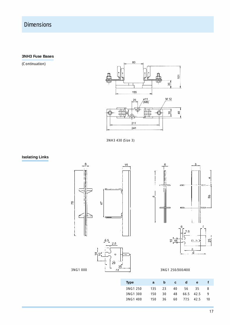
Isolating Links
Together with fuse bases, these isolating links can effectively be used to serve asremovable links in feeders instead of isolators.
These are made of silver plated copper alloy in one piece and are similar inconstruction to the ribbed contact knife of the fuse link.
Rating Order No. Std. Pkg. WeightUnit (Nos.) per unit
(Kg)
160 3NG1 000 1 0.075
250 3NG1 250 1 0.175
400 3NG1 300 1 0.260
630 3NG1 400 1 0.280
Fuse PullerType 3NX1 010, 3NX1 011suitable for all sizes offuse links and isolatinglinks.
Selection & Ordering DataLow-Voltage Fuses
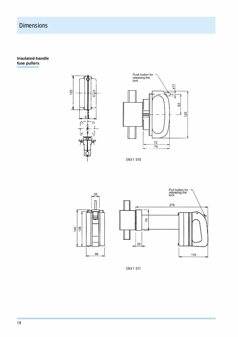
Fuse Pullers
Fuse puller with special insulated handle makes it possible to change fuses evenunder live conditions (on load). A mechanical lock provided on the fuse pullerprevents the fuse link from drapping out the puller. The fuse link can be released bymerely pressing the push button provided on a fuse puller.
Order No. Std. Pkg. WeightUnit (Nos.) per unit
(Kg)
Fuse Puller 3NX1 010 1 0.205
3NX 1 011 1 0.560
3NX1 010
3NX1 011� For dimensional drawings, see pages 17 & 18.

11
Range3NA3 8
Size00c/00
Operating classgG
Rated voltageAC 500 V / DC 250 V
Rated current2 - 160 A
LV HRC Fuse Links Time-current characteristic chart
Peak let-through current chart
Characteristic Curves
Pre
-arc
ing
time
(sec
)
Effective short circuit current (A)
Effective short circuit current (A)
Max
imum
Let
Thr
ough
Cur
rent
(A)
� Peak short circuitcurrent withmaximum DCcomponent
� Peak short circuitcurrent without DCcomponent

12
Range3NA3 1
Size1
Operating classgG
Rated voltageAC 500 V / DC 440 V
Rated current50 - 250 A
LV HRC Fuse Links Time-current characteristic chart
Peak let-through current chart
Characteristic Curves
Pre
-arc
ing
time
(sec
)
Effective short circuit current (A)
Effective short circuit current (A)
Max
imum
Let
Thr
ough
Cur
rent
(A)
� Peak short circuitcurrent withmaximum DCcomponent
� Peak short circuitcurrent without DCcomponent

13
Range3NA3 2
Size2
Operating classgG
Rated voltageAC 500 V / DC 440 V
Rated current315 - 400 A
LV HRC Fuse Links Time-current characteristic chart
Peak let-through current chart
Characteristic Curves
Pre
-arc
ing
time
(sec
)
Effective short circuit current (A)
Effective short circuit current (A)
Max
imum
Let
Thr
ough
Cur
rent
(A)
� Peak short circuitcurrent withmaximum DCcomponent
� Peak short circuitcurrent without DCcomponent

14
LV HRC Fuse Links Time-current characteristic chart
Peak let-through current chart
Range3NA3 3
Size3
Operating classgG
Rated voltageAC 500 V / DC440 V
Rated current315 - 630 A
Characteristic Curves
Pre
-arc
ing
time
(sec
)
Effective short circuit current (A)
Effective short circuit current (A)
Max
imum
Let
Thr
ough
Cur
rent
(A)
� Peak short circuitcurrent withmaximum DCcomponent
� Peak short circuitcurrent without DCcomponent

15
LV HRC fuse links
Sizes 1 2 3
Type 3NA3 1 3NA3 2 3NA3 3
a1 135 150 150
a2 71.5 71.5 71.5
a3 65 65 65
b 21 30 36
c1 40 48 60
c2 9 9 9
d 3 3 3
e1 46 57 70
e2 46 57 70
e3 25 25 25
f 8.5 11.5 12
Size: 00c Size: 00
3NA3 1 2 & 3
3NA3 8.. 3NA3 8..
Dimensions

16
Dimensions
3NH3 Fuse Bases
3NH3 030 (Size 00)
3NH3 330 (Size 2)3NH3 230 (Size 1)
3NH3 032 (Size 00)
17
3NG1 000 3NG1 250/300/400
Dimensions
Type a b c d e f
3NG1 250 135 23 40 56 35 8
3NG1 300 150 30 48 66.5 42.5 9
3NG1 400 150 36 60 77.5 42.5 10
3NH3 430 (Size 3)
Isolating Links
3NH3 Fuse Bases
(Continuation)
18
Insulated-handlefuse pullers
3NX1 010
Dimensions
3NX1 011

19
Notes

20
Notes

21

Your Partners
• Bhubaneshwar 751007335, Shahidnagar, Orissa� +91 674 522839
• Baroda 39000943, Vivekanand SocietyMakarpura Road, Opp. ONGC Office� +91 0265 658213
• Bokaro 827001110, 1st floorCo-operative ColonyBokaro Steel City� +91 6542 46185
• Cochin 682016Preethi Building1st floor, M G RoadErnakulam� +91 484 380201, 380506Fax +91 484 371564
• Durg 491001MIG-258, PadmanabhpurMadhya Pradesh� +91 788 320337
• Durgapur 713216A-32, Abanindranath Bithi, 1st FloorNon-company, City Centre, W.B.�/Fax +91 6542 46185
• Guwahati 781019C/o Mr. Mahendranath Chamua,Kahilipara, KalyaninagarAssam� +91 361 620332
• Hardwar 249403H-18, Shivalik NagarPhase II, B.H.E.L.Ranipur� +91 133 440767
• Indore 45200178, Anand NagarChitawad Road� +91 731 402341Fax +91 731 400735
• Jaipur 302017B-310, Malviya NagarHari Marg, Rajasthan�/Fax +91 141 521967
• Jallandhar 144001958-C, Urban Estates Phase IIJallandhar City� +91 181 463201
• Kanpur 208002Flat No 3 House No 3/254Classic Apartment, Vishnupuri, U.P.�/Fax +91 512 561773
• Kolhapur 416008Deo Datta, Plot No. 9Ideal Co-op. Hsg. SocietySagarmal�/Fax +91 231 652209
• LucknowC-447, Indra Nagar� +91 522 351773
• Ludhiana 14100167, Defence Colony (Shamsher Nagar)BRS Nagar� +91 161 457199
• Madurai 625003E-212, Santhanam RoadT.V.S. Nagar� +91 452 673388
• Nagpur 440 025F1 Gulmohar Apartment,1st FloorOpp. Sonegaon Police StationWarda Road� +91 712 260697Fax +91 712 260698
• Nashik 422002Flat No 3, Bldg No 63Santoshi BuildingUshakiran Society,Triambak Road�/Fax +91 253 311029
• Panchkula 134401902, Sector 16� +91 172 578902, 666602Fax +91 172 578903
• Rourkela 769006Post Box No 51, F/1 Sector 2� +91 661 546504, 542897Fax +91 661 542897
• Shaktinagar 231222Panchwati Guest HouseKota Basti, Uttar Pradesh� +91 544 638167Fax +91 544 632518
• Vadodara 390009130 Vijay Nagar, Tarsali� +91 265 647509
• Visakhapatnam 530002SF-2 Door No. 57-11-14/10Mahalaxmi Enclave,Maddilapalem (Isakathota)Near Krishna College� +91 891 539601
Registered & Corporate Office:
130 Pandurang Budhkar MargWorli, Mumbai 400018� +91 22 4934080, 4934161Fax +91 22 4950552
Sales Offices:• Ahmedabad 380009
1st Floor, Shanti ChamberTerapanth Marg, Navrangpura� +91 79 6581803, 6580594Fax +91 79 6586103
• Bangalore 561229No. 84, Keonics Electronics CityHosur Road� +91 80 8521122-29Fax +91 80 8521180
• Calcutta 70007843 Shanti PalliEastern Metropolitan Bypass� +91 33 4421134, 4421135Fax +91 33 4421137
• Chennai 600034144, Mahatma Gandhi Road� +91 44 823 1826/1124Fax +91 44 825 5731/5728
• Coimbatore 641018No 29 First FloorAddis Street, Grey Town� +91 422 380908, 380270Fax +91 422 380271
• Mumbai 400018130 Pandurang Budhkar Marg,Worli� +91 22 4934080, 4934161Fax +91 22 4931358
• New Delhi 1100024A, Ring Road, I.P. Estate� +91 11 3738589, 3738594Fax +91 11 3314178
• Pune 411004Vasant Vihar, 1205/2/6 Shirole RoadShivajinagar� +91 20 5539577/9760Fax +91 20 5539758
• Secunderabad 5000259-1-87/119/2 1st FloorSt. John’s Road� +91 40 7702552, 7704544Fax +91 40 7702951
Resident Sales Engineers• Aurangabad 431005
5, Navyug Colony, Padampura� +91 240 388203
• Bhopal 46201610, Ranjit Apts., Shalimar EnclaveE/3, Arera Colony Extn.� +91 755 555956/7Fax +91 755 557295
Marketing Office:
Standard Products DivisionElectrical Installation TechnologyThane Belapur RoadThane 400601� +91 22 7600074Fax +91 22 7600074
Siemens LtdET-01-107-003
'Product development is a continuous process. Consequentlythe data indicated in this folder is subject to change withoutprior notice. For latest issue contact our Sales Office.'
Visit the Siemens AG ET website at :http://www.ad.siemens.de/et 01