siemens digital industries software integrated
TRANSCRIPT

Executive summaryElectrical systems are rapidly growing, regardless of the industry or application. The increasing size of electrical networks can raise the cost of vehicle development two-fold due to the innate cost of the additional wiring and components and the time and resources required to design an ever more complex system. ECAD-MCAD integration supports the develop-ment of mechatronic products that are growing in both demand and complexity. The increased visibility between domains is critical for cross-functional design teams to maximize efficiency and produce high quality products on shrinking timelines.
Siemens Digital Industries Software
siemens.com/vesys
Integrated electromechanical wire harness design

White paper | Integrated electromechanical wire harness design
2Siemens Digital Industries Software
Introduction
Electrical systems are rapidly growing, regardless of the industry or application. The increasing size of electrical networks can raise the cost of vehicle development two-fold due to the innate cost of the additional wiring and components and the time and resources required to design an ever more complex system. That complexity can spell even greater problems during revisions and re-designs. As there are more pathways and circuits, the likelihood of induced errors rises.
These errors can be incredibly costly as well. Errors in the electrical systems or wiring harness, or the integra-tion of these systems into the vehicle can lead to incor-rect functionality or, worse, danger to the customer. For instance, a failure in electro-mechanical co-design can cause the wiring harness to rub on mechanical compo-nents, creating an electrical short that inflates the air-bags unexpectedly. In addition to the cost of identifying and recalling affected vehicles, the manufacturer may also be fined for such an error, costing additional money and hurting brand image.
In particular, electrical and mechanical integrations are increasingly critical as products become more electro-mechanical in nature. With advances in technology comes demand for more complex electrical and mechanical designs. As noted above, this complexity creates significant challenges for each respective design team on their own. But when the product is electrome-chanical in nature, such as an electrical wire harness, mechanical and electrical designers must account for needs and challenges across both domains.
For example, mechanical designers need to verify the physical space constraints of the harness, which are affected by the bundling thickness and, therefore, finalized wiring content (figure 1). Likewise, the electri-cal designers rely on real-world wire lengths to conduct voltage drop analysis and fuse sizing calculations to ensure the correct circuit behavior. And the harness designer needs to reproduce the 3D harness topology in 2D and combine it with electrical data. If the 2D harness is just a derivative of the 3D harness, why should it need to be recreated from scratch?
Figure 1. In traditional flows, electrical and mechanical designers are often isolated from critical information contained in the other domain.

White paper | Integrated electromechanical wire harness design
3Siemens Digital Industries Software
Modern tools address today’s challenges
In the attempt to address these issues, new E/E systems and wiring harness tools are built to facilitate collabora-tion to reduce design costs, design cycles and risk. A design flow incorporating modern tools, such as VeSys from Siemens Digital Industries Software, supports collaboration and concurrent design between the elec-trical and mechanical domains (figure 2). The mechani-cal designer defines the harness geometry and fixtures along with reserving space in the vehicle or machine. Meanwhile, the electrical designer masters the electrical content for the system, creating the needed wiring diagrams and conducting analyses along the way. The mechanical and electrical disciplines can work indepen-dent of each other, but can easily pass data back and forth as it becomes available. Then, the harness designer combines the MCAD and electrical data to fully define the electromechanical harness product.
These interactions enhance the visibility between the ECAD and MCAD domains, supporting the co-design of mechatronic or electromechanical products. As a result, the impacts of electrical and mechanical-specific deci-sions on the other domain are better understood, improving the overall design quality. In addition, the data exchange supported by modern tools eliminates the need to manually transfer data between the envi-ronments, saving considerable design time and reduc-ing the potential for manually-induced errors.
Figure 2. Digitalization allows the electrical and mechanical domains to work closely together with greater insight.

White paper | Integrated electromechanical wire harness design
4Siemens Digital Industries Software
Direct connections remove domain silos
In-depth example
These robust integration capabilities are enabled via two key constructs. First, a framework of cross-domain bridges and adapters handle the exchange of informa-tion between MCAD tools and the electrical design environment. Second, APIs from each MCAD application are used to develop plugins that are deployed within the MCAD products. These plugins ensure a seamless integration of the data between the tools. VeSys, for example, supports integrations with CREO, NX, Solid Edge, Solid Works and CATIA V5.
In this example, we will walk through the various ways in which contemporary electrical systems and wiring harness engineering solutions can integrate with their mechanical counterparts.
To begin, we will focus on the exchange of data between the harness designer, electrical engineer and the mechanical engineer. As we will see, the wiring information from the electrical and wiring harness solution will be bridged out to the mechanical domain as a wiring PLM XML file. Once the data has been exported to the MCAD tool, connectors will be auto assigned, and wires will be routed automatically.
Initially the MCAD design contains no electrical content, only the bundles and connectors that have been added by the mechanical designer. A direct connection between the tools can be established with the push of a button, enabling the real-time import and export of data. In this case, the mechanical design will receive electrical data in a wiring PLM XML file. An integrated filter mechanism allows the user to select the specific harness designs to exchange. The electrical engineer
For NX and Solid Edge, an advanced data exchange enables real-time data import and export as well as cross-highlighting for ease of use and analysis during wiring and harness design. The functionality automati-cally switches between wiring mode and harness mode exchange as needed within the same application. Any selected objects in the MCAD solution will be cross-highlighted in the electrical diagram and vice-versa. For example, selecting a wire in the electrical solution will cross-highlight the corresponding shortest route path and devices that the wire connects to in the mechanical environment.
selects just the driver-side door design and exports the electrical content to the mechanical tool. A report shows the number of connectors, splices and wires that were passed.
The MCAD tool is now populated with the electrical data (figure 3). With this data, the mechanical engineer can
Figure 3. The electrical designer exports wiring data to the MCAD environment.

White paper | Integrated electromechanical wire harness design
5Siemens Digital Industries Software
automatically assign the needed connectors and manu-ally assign any remaining components, such as splice locations. The automatic assignment of connectors can be done by part number or any other component attri-bute. Then, the mechanical designer can automatically route the wires at the component level (figure 4). The automated flow of data between design tools provided the mechanical designer with all the data required to assign connector part numbers and route wires. As a result, the mechanical designer was able to quickly and accurately replicate the connectivity from the wiring diagram, saving considerable time over manual and error-prone methods.
Figure 4. With the electrical data, the mechanical designer is able to automatically route wiring at the component level.
Now that the mechanical designer has routed the wires in the driver door harness, they have been updated with accurate lengths according to the three-dimensional constraints of the physical design. This is valuable infor-mation with which electrical designers can conduct additional analysis and further verify electrical behavior. This time, we will pass data from the mechanical solu-tion back to the electrical domain.
With the ECAD and MCAD tools already connected, the electrical designer simply needs to import the needed
data from the mechanical environment. As with the export done earlier, a report is provided to describe the data that has been brought back into the electrical environment. All the wires in the ECAD solution have now been updated with correct lengths from the mechanical design. This will allow the electrical designer to perform more accurate voltage drop analy-sis and fuse sizing calculations.
With VeSys and NX, from Siemens Digital Industries Software, the electrical designer can take advantage of intelligent cross-probing between the electrical and mechanical environments to further verify that all data transfers have occurred correctly. An object of interest, such as a specific connector, can be selected, highlight-ing it and any related connectivity in both tools (figure 5). This provides the designer with a visual indication of how each component is wired. Individual wires can also be selected to identify how they will traverse the har-ness and the context of the larger parent assembly. Cross-probing and the transfer of accurate wiring data can help the electrical engineer to catch and fix poten-tial issues early before they are propagated down-stream, where they become immensely expensive.
Figure 5. Intelligent cross-probing allows designers to quickly view objects in both the electrical and mechanical environments, and highlights any related connectivity.
White paper | Integrated electromechanical wire harness design
6Siemens Digital Industries Software
Harness synchronization
Next, we will see how the two-dimensional harness design in the electrical tool can synchronize with the physical harness from the mechanical environment.
The process is started by importing the 3D harness topology from the mechanical tool via a PLM XML file. The ECAD tool receives this data and flattens the har-ness to produce a 2D diagram. The content that is trans-ferred from the mechanical environment to the harness engineering tool is dependent on the preferred flow of the company. Some may prefer to first rout wires in the mechanical design tool before harness integration. Others may choose to only import the 3D harness topol-ogy from the mechanical tool while getting the electri-cal content from the electrical design. In this example, the mechanical environment has only exported the 3D harness topology.
VeSys offers a number of options that allow designers to control how data is exchanged between the mechan-ical and harness tools. For example, various choices for the type of import enable the designer to update the harness with the option to preserve electrical content, replace all content in the current design or only replace wires and multi-cores.
Bridge options provide further control. The tool can automatically center and scale the harness as well as define margins to fit the designer’s desired border. Next, a configurable auto-link function controls how matches are made between external and internal har-ness data, while a translation feature controls the trans-lation of both part numbers and codes, which influ-ences how component data is updated during bridge operations. Finally, an automated change policy man-ages differences between the mechanical and electrical designs when bridging in harness data.
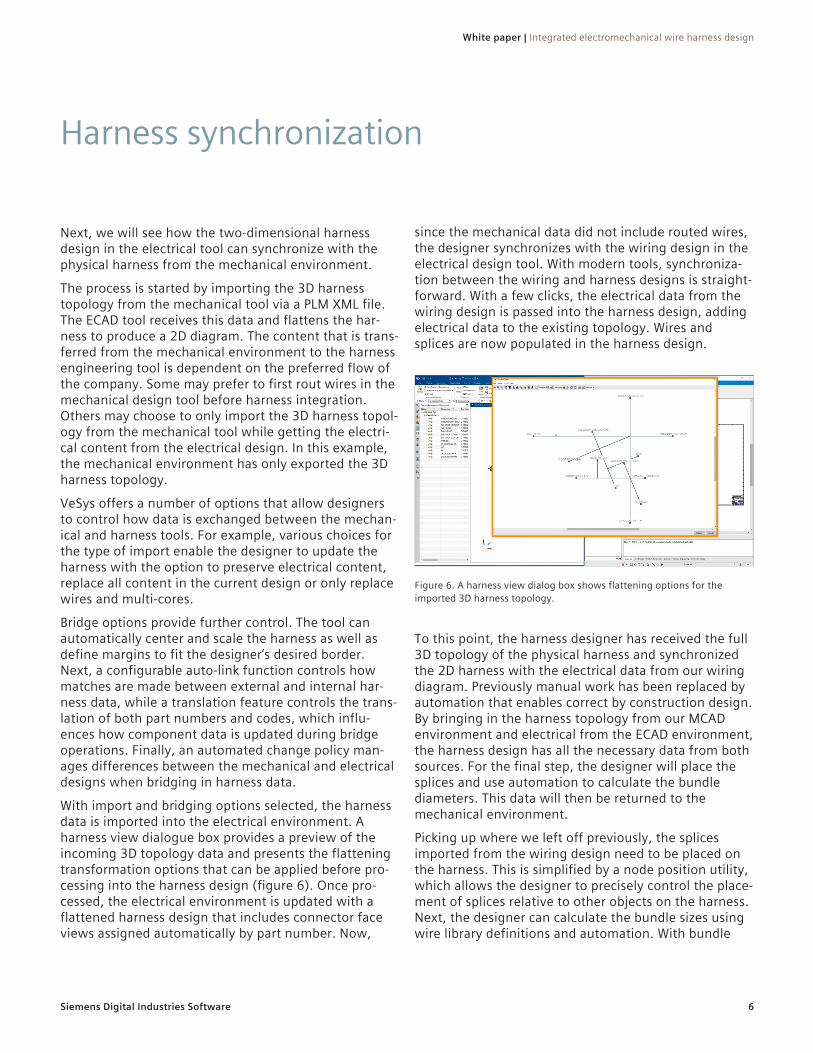
With import and bridging options selected, the harness data is imported into the electrical environment. A harness view dialogue box provides a preview of the incoming 3D topology data and presents the flattening transformation options that can be applied before pro-cessing into the harness design (figure 6). Once pro-cessed, the electrical environment is updated with a flattened harness design that includes connector face views assigned automatically by part number. Now,
since the mechanical data did not include routed wires, the designer synchronizes with the wiring design in the electrical design tool. With modern tools, synchroniza-tion between the wiring and harness designs is straight-forward. With a few clicks, the electrical data from the wiring design is passed into the harness design, adding electrical data to the existing topology. Wires and splices are now populated in the harness design.
Figure 6. A harness view dialog box shows flattening options for the imported 3D harness topology.
To this point, the harness designer has received the full 3D topology of the physical harness and synchronized the 2D harness with the electrical data from our wiring diagram. Previously manual work has been replaced by automation that enables correct by construction design. By bringing in the harness topology from our MCAD environment and electrical from the ECAD environment, the harness design has all the necessary data from both sources. For the final step, the designer will place the splices and use automation to calculate the bundle diameters. This data will then be returned to the mechanical environment.
Picking up where we left off previously, the splices imported from the wiring design need to be placed on the harness. This is simplified by a node position utility, which allows the designer to precisely control the place-ment of splices relative to other objects on the harness. Next, the designer can calculate the bundle sizes using wire library definitions and automation. With bundle

White paper | Integrated electromechanical wire harness design
7Siemens Digital Industries Software
diameters calculated, the harness designer is ready to pass data back to the mechanical tool. After exporting the harness data, bundle solids are computed based on diameter data from the harness design tool, and auto-matically added to the 3D harness in the MCAD solution (figure 7). Splices are also automatically added based on their locations in the harness design that were defined using the node position utility.
Figure 7. Bundle solids are automatically created in the MCAD environment based on data from the ECAD solution.
Here, the designer can make use of cross-probing again to help verify the data came over correctly. It’s also possible for the mechanical designer to make modifica-tions to the splice positioning and transfer the changes back to the electrical and harness tool. During this data
transfer, the designer chooses to preserve electrical content so that all the ECAD data in the existing design is only added to or updated, but not deleted. The mechanical engineer now has accurate bundle diam-eters and splice positions to work with, allowing them to perform interference studies to determine if the harness will successfully fit within the target application enclosure. If any further updates are required to the 3D harness, the changes can be easily passed back to the electrical and harness solution to update the design.
In this example, we have explored the various integra-tions between VeSys and NX, exchanging both wiring and harness data (figure 8). The underlying advantages provided by ECAD-MCAD integration can be found throughout the flow, reducing errors, speeding up design time and enhancing collaboration between both domains.
Figure 8. The example above examined a cross-domain flow of data between modern ECAD and MCAD solutions.
ECAD-MCAD integration supports the development of mechatronic products that are growing in both demand and complexity. The increased visibility between domains is critical for cross-functional design teams to maximize efficiency. Likewise, advanced automation in both design and the handling of data exchange
provides designers more time to focus on design valida-tion and innovation, both of which improve overall design quality. With both electrical and mechanical portions of the design being of equal importance, fully understanding both aspects will, in the end, result in a better product.
The power of electrical-mechanical integration

siemens.com/software© 2021 Siemens. A list of relevant Siemens trademarks can be found here. Other trademarks belong to their respective owners.
83732-C2 5/21 H
About Siemens Digital Industries SoftwareSiemens Digital Industries Software is driving transfor-mation to enable a digital enterprise where engineer-ing, manufacturing and electronics design meet tomor-row. The Xcelerator™ portfolio, the comprehensive and integrated portfolio of software and services from Siemens Digital Industries Software, helps companies of all sizes create and leverage a comprehensive digital twin that provides organizations with new insights, opportunities and levels of automation to drive innova-tion. For more information on Siemens Digital Industries Software products and services, visit siemens.com/software or follow us on LinkedIn, Twitter, Facebook and Instagram. Siemens Digital Industries Software – Where today meets tomorrow.
Siemens Digital Industries Software
HeadquartersGranite Park One 5800 Granite Parkway Suite 600 Plano, TX 75024 USA +1 972 987 3000
AmericasGranite Park One 5800 Granite Parkway Suite 600 Plano, TX 75024 USA +1 314 264 8499
EuropeStephenson House Sir William Siemens Square Frimley, Camberley Surrey, GU16 8QD +44 (0) 1276 413200
Asia-PacificUnit 901-902, 9/FTower B, Manulife Financial Centre223-231 Wai Yip Street, Kwun TongKowloon, Hong Kong +852 2230 3333