fred mendonça - siemens digital industries...
TRANSCRIPT
Turbomachinery Applications with STAR-CCM+
Fred MendonçaFred MendonçaTurbomachinery Sector Manager
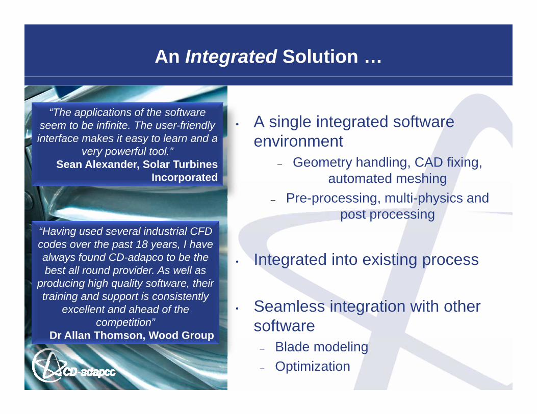
An Integrated Solution …
• A single integrated software “The applications of the software
seem to be infinite. The user-friendly g genvironment
– Geometry handling, CAD fixing, automated meshing
seem to be infinite. The user friendly interface makes it easy to learn and a
very powerful tool.”Sean Alexander, Solar Turbines
Incorporated automated meshing
– Pre-processing, multi-physics and post processing
co po ated
“Having used several industrial CFD
• Integrated into existing process
Having used several industrial CFD codes over the past 18 years, I have always found CD-adapco to be the best all round provider. As well as
producing high quality software their
• Seamless integration with other software
producing high quality software, their training and support is consistently
excellent and ahead of the competition”
Dr Allan Thomson, Wood Group– Blade modeling– Optimization
Dr Allan Thomson, Wood Group
… from interaction Across the Industry
STAR-Konferenz Deutschland 2009, Berlin 9-10 Nov. 2009
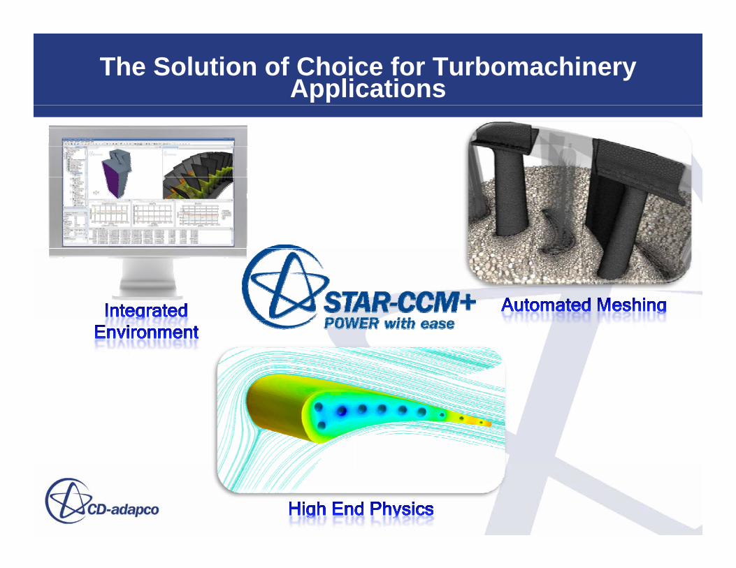
The Solution of Choice for TurbomachineryApplications
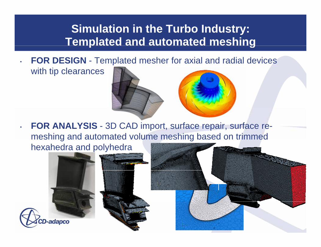
Simulation in the Turbo Industry:Templated and automated meshingp g
• FOR DESIGN - Templated mesher for axial and radial devices with tip clearances
• FOR ANALYSIS - 3D CAD import, surface repair, surface re-meshing and automated volume meshing based on trimmedmeshing and automated volume meshing based on trimmed hexahedra and polyhedra
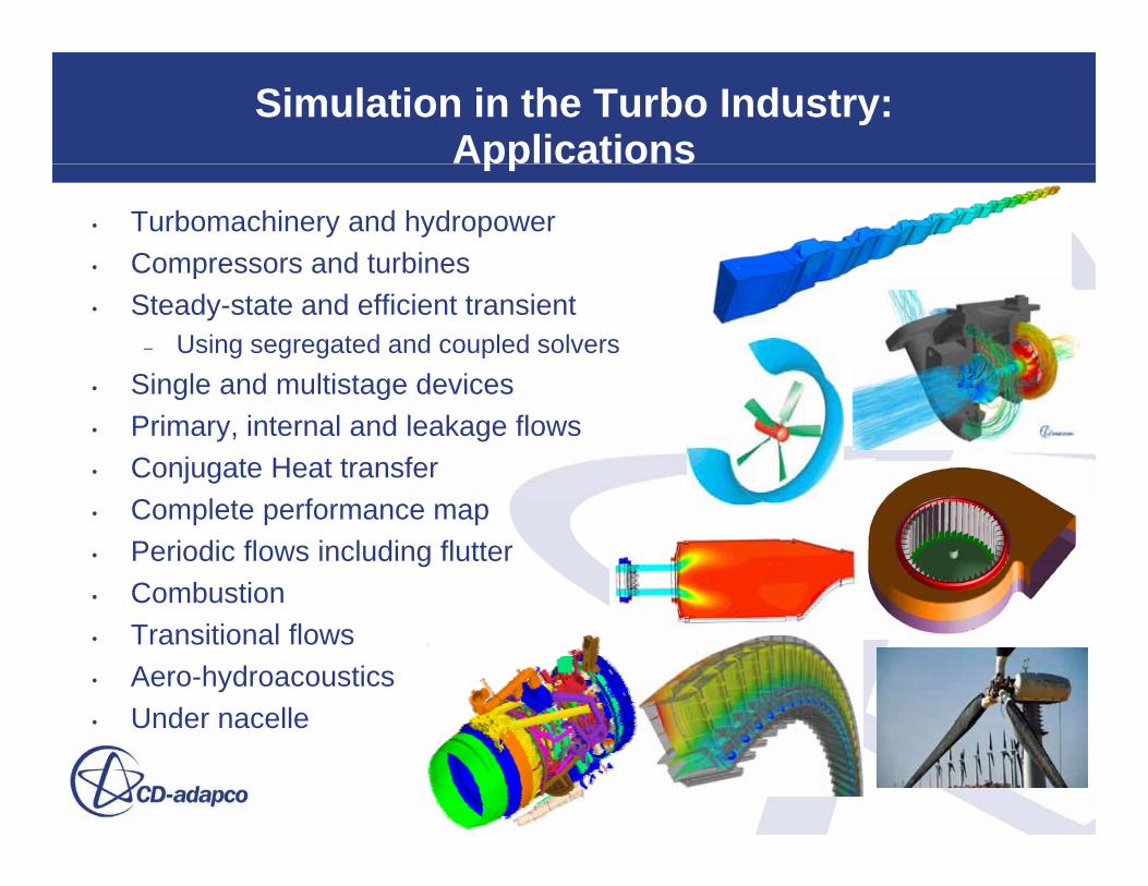
Simulation in the Turbo Industry:Applicationspp
• Turbomachinery and hydropower• Compressors and turbinesp• Steady-state and efficient transient
– Using segregated and coupled solvers• Single and multistage devices• Single and multistage devices• Primary, internal and leakage flows• Conjugate Heat transfer
C l t f• Complete performance map• Periodic flows including flutter• Combustion• Transitional flows• Aero-hydroacoustics• Under nacelle• Under nacelle
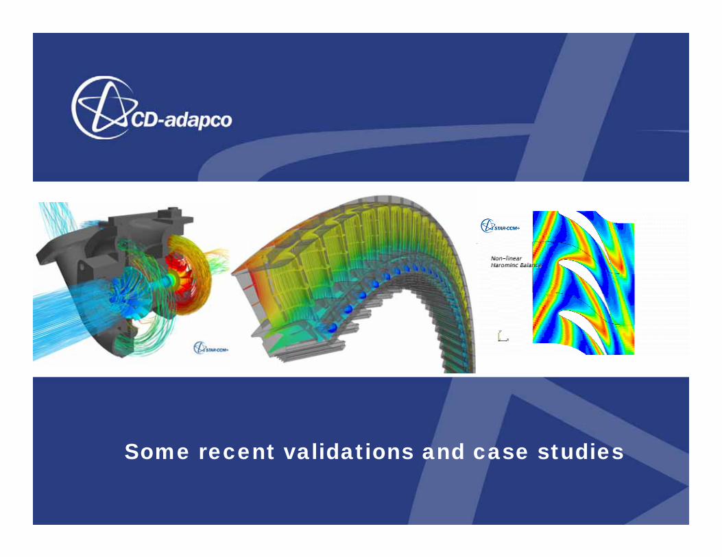
Some recent validations and case studiesSome recent validations and case studies
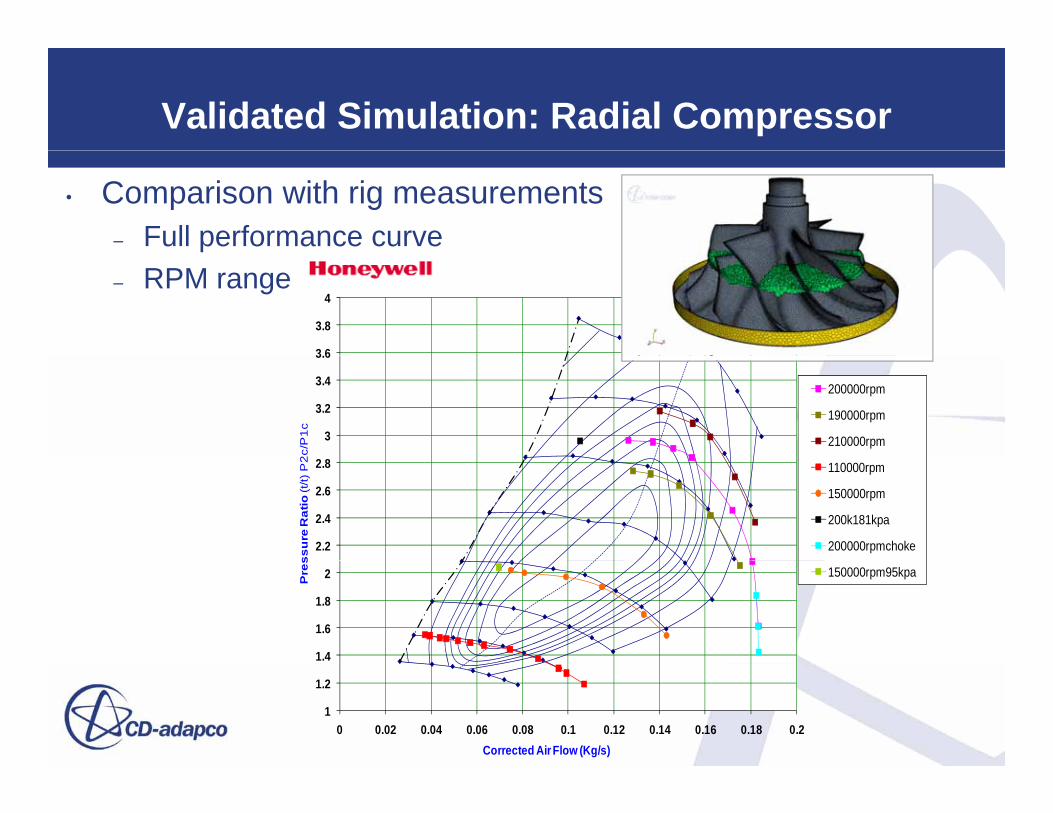
Validated Simulation: Radial Compressor
• Comparison with rig measurements– Full performance curve
3 6
3.8
4– RPM range
3
3.2
3.4
3.6
2c/
P1
c
200000rpm
190000rpm
210000rpm
2.2
2.4
2.6
2.8
ssu
re R
atio
(t/t)
P2
110000rpm
150000rpm
200k181kpa
200000rpmchoke
1.4
1.6
1.8
2Pre
s
150000rpm95kpa
1
1.2
0 0.02 0.04 0.06 0.08 0.1 0.12 0.14 0.16 0.18 0.2Corrected Air Flow (Kg/s) �
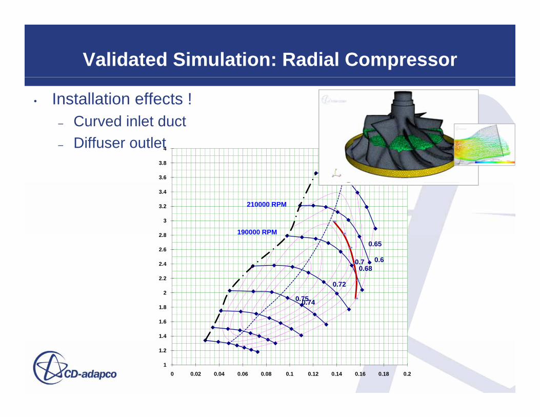
Validated Simulation: Radial Compressor
• Installation effects !– Curved inlet duct
3.6
3.8
4– Diffuser outlet
190000 RPM
210000 RPM
2 8
3
3.2
3.4
0.6
0.65
0.680.7
0.722.2
2.4
2.6
2.8
0.740.75
1.4
1.6
1.8
2
1
1.2
0 0.02 0.04 0.06 0.08 0.1 0.12 0.14 0.16 0.18 0.2

Validated Simulation: Axial Compressor
• NASA Rotor37 – AGARD-AR-355– Comparison of High-Re and Low-Re wall resolution– Comparison of turbulence models
Pressure ratio
Isentropic efficiencyIsentropic efficiency
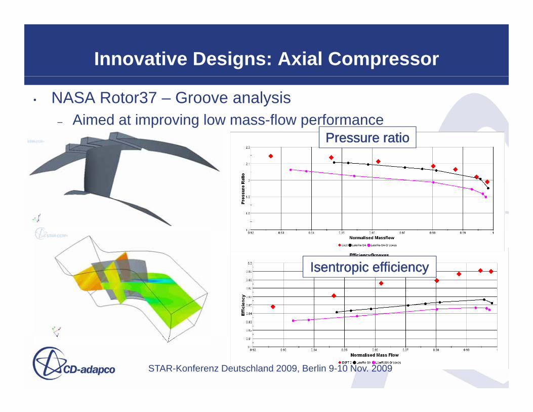
Innovative Designs: Axial Compressor
• NASA Rotor37 – Groove analysis– Aimed at improving low mass-flow performance
Pressure ratio
Isentropic efficiency
STAR-Konferenz Deutschland 2009, Berlin 9-10 Nov. 2009

AITEB-2 WP4.2 turbine blade end-wall cooling
• Solution Timescales from “blind start”– CAD to CHT Polyhedral mesh : 3 HOURS– CHT Polyhedral Volume solution : 2 DAYS– Hexahedral solution (fluid only) : 3rd DAY
CAD
Volume Meshes
CAD
Solutions
Surface remesh
STAR-Konferenz Deutschland 2009, Berlin 9-10 Nov. 2009

Blade Pressure DistributionAITEB-2 WP4.2 turbine blade end-wall cooling
1.1 Blade outer wall plane at z = 96.8%
Blade Outer wall Absolute Pressure Comparison
0 8
0.9
1
0.6
0.7
0.8
Ps
/ P01
0.4
0.5
CFD - FLUENT (Non-Conjugate)EXPERIMENT
0.2
0.3
0.025 0.045 0.065 0.085 0.105 0.125
EXPERIMENTCFD - CCM+ (Conjugate)CFD - CCM+ (Non-Conjugate)
X-Coordinate (m)
STAR-Konferenz Deutschland 2009, Berlin 9-10 Nov. 2009
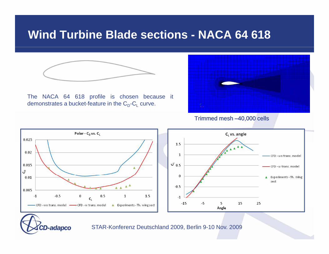
Wind Turbine Blade sections - NACA 64 618
The NACA 64 618 profile is chosen because itdemonstrates a bucket-feature in the CD-CL curve.
Trimmed mesh – 40,000 cells
STAR-Konferenz Deutschland 2009, Berlin 9-10 Nov. 2009
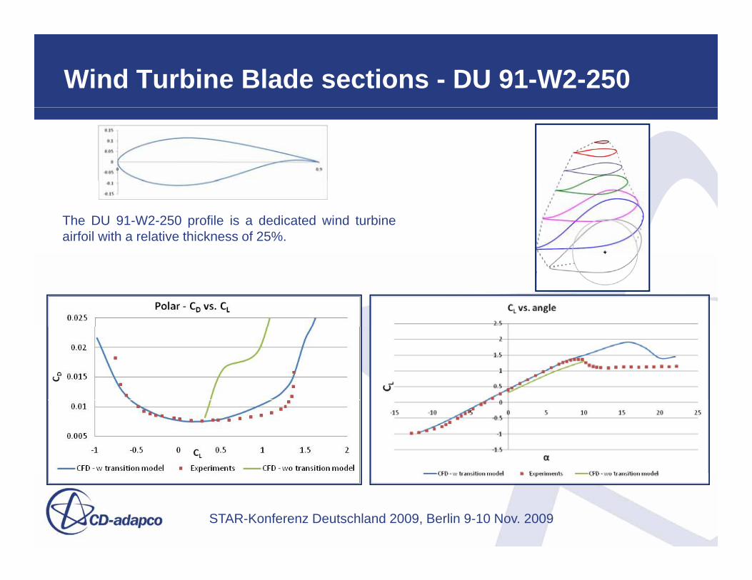
Wind Turbine Blade sections - DU 91-W2-250
The DU 91-W2-250 profile is a dedicated wind turbineairfoil with a relative thickness of 25%.
STAR-Konferenz Deutschland 2009, Berlin 9-10 Nov. 2009

Harmonic Balance – Rational for fast transient analysis of periodic flows
• Devices are commonly multi-row and multi-stage• Stator/mounts and rotors commonly have unequal
pitchespitches
• Steady-state methods “mix-out” or “freeze” the interaction between stator and rotor This is inaccurateinteraction between stator and rotor. This is inaccurate, but efficient
• Transient methods overcome the inaccuracies by sliding the mesh at the interface between stator andsliding the mesh at the interface between stator and rotor. This is accurate, but inefficient, especially when the number of stators and rotors are unequal
• Harmonic Balance, specifically for periodic flowsaffords both benefits of efficiency and accuracy. Typically costs 1/10th of equivalent transient
C rrent implementation is for ideal gases onl• Current implementation is for ideal gases only
STAR-Konferenz Deutschland 2009, Berlin 9-10 Nov. 2009

Harmonic Balance: Stator-Rotor Wake Interaction
• D4 compressor
• Hodson turbine
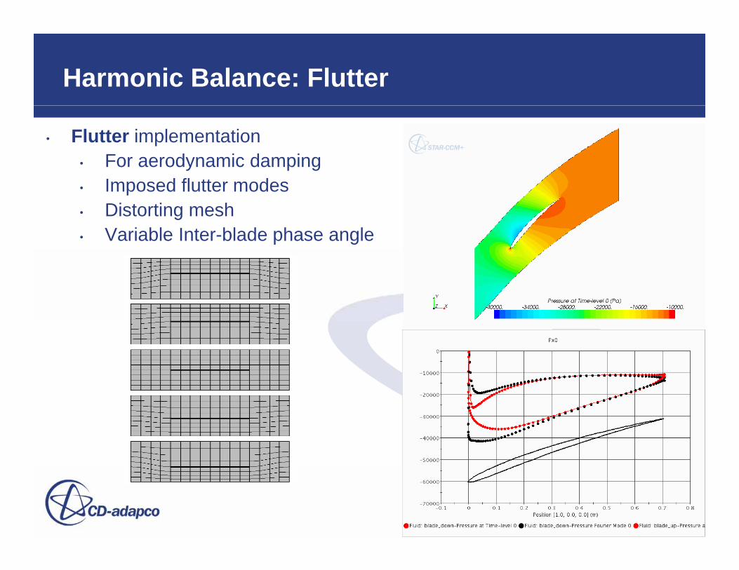
Harmonic Balance: Flutter
• Flutter implementation• For aerodynamic damping• Imposed flutter modes• Distorting mesh• Variable Inter-blade phase angle
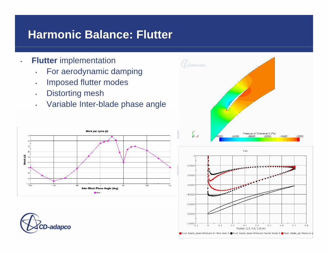
Harmonic Balance: Flutter
• Flutter implementation• For aerodynamic damping• Imposed flutter modes• Distorting mesh• Variable Inter-blade phase angle
Summary
• 1st level2nd Level
• CD-adapco continues to pursue – 2nd Level
» 3rd Level- 4th Level
• Integrated, Automated, Innovativesolutions for the Turbomachinery Industry
Many thanks for your AttentionMany thanks for your Attention