sidc report57
TRANSCRIPT
SIDCInternship Report
Submitted to:Project Director SIDC
Submitted by:
Adeel Arif, 2nd year, BSc. Chemical EngineeringUniversity of Engineering and Technology
Lahore
Supervisors: Engg. Amjad Farooq
Start Date of Internship: 2nd August, 2015End Date of Internship: 27th August, 2015

Page | 1
SIDC Internship Report
Preface
The report encloses the work done during summer internship program at SportsIndustries Development Center (SIDC). The brief description of all the processesthat are being carried out in SIDC are documented in the report. The report is dividedinto sections for ease of study. Moreover each and every machine and apparatus usedhere is explicitly explained to encourage the learners towards its study. At last thesafety remedies of each and every section are listed and possible suggestions aregiven to improve the quality of work.
I tried my best to keep the report simple yet technical. Hope I succeed in my attempt.
Adeel Arif
Page | 2
SIDC Internship Report
Acknowledgment
This report would not come to an end if I had not gained a lot of help from the wholestaff working in SIDC cheerful environment. SIDC working environment is quietmotivate. Everyone here tries his best to accomplish the task assigned to him withintime and thus stress never comes in the way.
I would really thank to Engg. Shakeel and Engg. EhsanUllah for their guidance anddelivering some technical knowledge helpful for me in future. Not only guiding mebut listening to my ideas and encouraging me on my work. I am also indebted to mySupervisor Engg. Amjad Farooq who seemed to have solutions to all my problemsand always enforcing me into the working environment.
Adeel Arif
Page | 3
SIDC Internship Report
Abstract
The report presents the following tasks completed during Summer Internshipprogram in SIDC
Manufacturing of football bladder from Raw Rubber batches Yarn winding and panel printing techniques Quality Control of each step carried in SIDC
All these workings were analyzed great fully and final product either it was Footballor Basketball was according to the FIFA Standards. Quality and Control departmentanalyzed the final product and minor errors of upto 10% were ignored and more ofit were rejected.The corporative environment and inter linking of all sections in SIDC helps to makea furnished and neat product. This environment in SIDC would be helpful for growthof its reputation in the market in future.
Adeel Arif
Page | 4
SIDC Internship Report
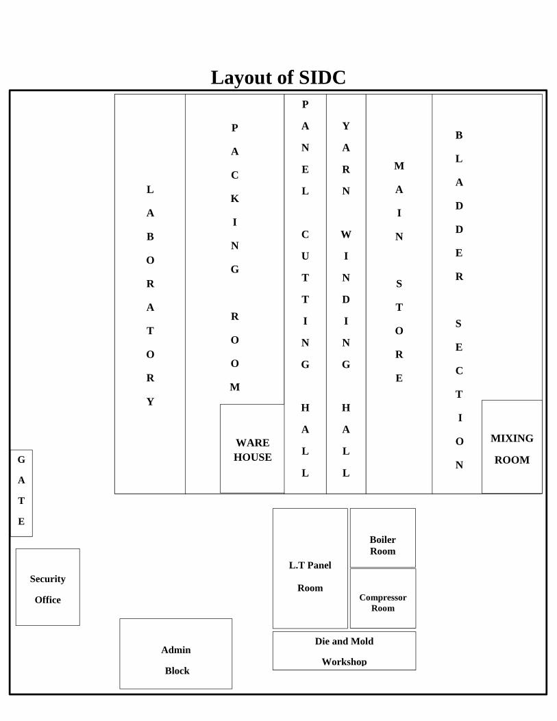
Layout of SIDC
Security
Office
Admin
Block
L.T Panel
Room
BoilerRoom
CompressorRoom
Die and Mold
Workshop
L
A
B
O
R
A
T
O
R
Y
P
A
C
K
I
N
G
R
O
O
M
WAREHOUSE
P
A
N
E
L
C
U
T
T
I
N
G
H
A
L
L
Y
A
R
N
W
I
N
D
I
N
G
H
A
L
L
M
A
I
N
S
T
O
R
E
B
L
A
D
D
E
R
S
E
C
T
I
O
N
MIXING
ROOMG
A
T
E
Page | 5
SIDC Internship Report
Table of ContentsIntroduction.................................................................................................................................................9
Project Objectives ................................................................................................................................... 9
Technological Aspects Of The Project .................................................................................................. 9
Estimated Project Cost ...........................................................................................................................9
Rubber: An Introduction .........................................................................................................................10
Classification of Rubber .......................................................................................................................10
Rubber Processing ....................................................................................................................................11
Some Basic Terminologies used in Rubber Industries ..........................................................................12
A Brief Description of Chemicals used in SIDC Processing Centre.....................................................13
I. Fillers..............................................................................................................................................13
II. Activator ....................................................................................................................................13
III. Accelerators ...............................................................................................................................14
IV. Rubber Sprayed Powder ..........................................................................................................14
V. Glue Paste ......................................................................................................................................14
Boiler Section.............................................................................................................................................15
Boilers used in SIDC .............................................................................................................................15
Types of Boilers .....................................................................................................................................16
Boiler Working......................................................................................................................................19
Safety Remedy for Boiler Use ..............................................................................................................20
Use of Boiler in SIDC............................................................................................................................21
Water Treatment of Boiler Feed Water..................................................................................................22
Hard Water............................................................................................................................................22
Soft Water..............................................................................................................................................22
Effects of using Untreated Hard Water ..............................................................................................22
Types of water treatment .....................................................................................................................23
Water Softening Mechanism................................................................................................................23
Resin Bed Regeneration .......................................................................................................................24
Compressor Room ....................................................................................................................................25
Types of Air Compressors ....................................................................................................................25
Screw Compressor ................................................................................................................................25
Main Components of Compressed Air Systems .................................................................................26
Page | 6
SIDC Internship Report
Brief Description of Compression System Components....................................................................27
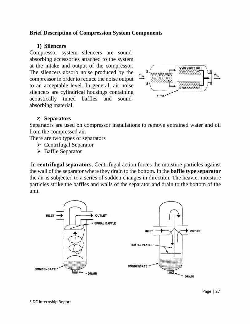
1) Silencers .....................................................................................................................................27
2) Separators ..................................................................................................................................27
3) Receivers ....................................................................................................................................28
4) Intercoolers and Aftercoolers ..................................................................................................28
5) Dryers.........................................................................................................................................29
Safety Remedy for Use of Air Compression System ..........................................................................30
Use of Air Compression System in SIDC............................................................................................30
Bladder Section .........................................................................................................................................31
Process Description Of Bladder Manufacturing................................................................................32
Machinery used in Bladder Section & Mixing Room ........................................................................33
1. Raw Rubber Cutter ..................................................................................................................33
2. Dispersion Mixer .......................................................................................................................33
3. Two Roll Mill.............................................................................................................................34
4. Four Roll Rubber Calendar .....................................................................................................36
5. Powder Spray & Cutting Machine ..........................................................................................37
6. Valve Hole Punch Machine ......................................................................................................37
7. Pneumatic Valve Seat stamp Machine ....................................................................................37
8. Bladder Forming Machine .......................................................................................................38
9. Bladder Vulcanizing Machine..................................................................................................38
10. Pin Cutting Machine .............................................................................................................39
11. Pin Inserting Machine ..........................................................................................................39
Yarn Winding Hall ...................................................................................................................................40
Purpose of Yarn Winding ....................................................................................................................40
Yarn Winding Machine ........................................................................................................................40
Carcass Bladder ....................................................................................................................................40
Panel Cutting Room..................................................................................................................................41
1) Football Sheet ....................................................................................................................................41
2) Panel Printing Machine ....................................................................................................................41
3) High Frequency Embossing Machine .............................................................................................41
4) Edge Turning Machine.....................................................................................................................42
5) Auto lamination Machine .................................................................................................................42
Page | 7
SIDC Internship Report
Basket Ball Manufacturing ......................................................................................................................43
Introduction...........................................................................................................................................43
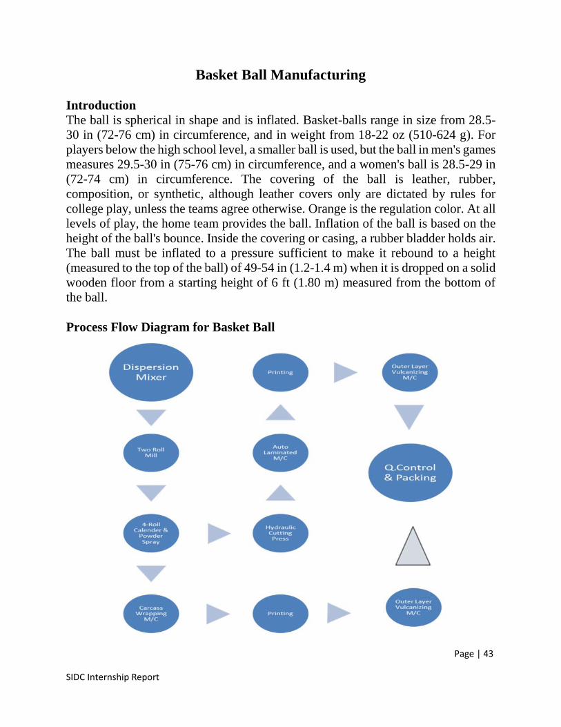
Process Flow Diagram for Basket Ball................................................................................................43
Process Description ...............................................................................................................................44
Labouratory Setup....................................................................................................................................45
Introduction...........................................................................................................................................45
List of Machines and Apparatus in Laboratory ................................................................................45
Description and Working of Machines ...............................................................................................46
1. Moving Die Rheometer .............................................................................................................46
2. Plasticity Tester .........................................................................................................................49
3. Demattie Flex Cracking Machine ............................................................................................49
4. Scott Volumeter.........................................................................................................................49
5. Sphericity Testing Machine......................................................................................................50
6. Compression Rebound Tester..................................................................................................50
7. Water Absorbtion Unit.............................................................................................................50
8. Air Inflator ................................................................................................................................50
9. Rotational Viscometer ..............................................................................................................51
10. Tensile Testing Machine .......................................................................................................51
11. Programmable Ball Mill .......................................................................................................52
12. Duro Meter (Hardness Testing Machine) ...........................................................................52
13. Vaccum Oven ........................................................................................................................53
14. Discloration Meter ................................................................................................................53
15. Nozzle Testing Machine........................................................................................................54
16. Ball Rebounce Tester ............................................................................................................54
17. Sample Cutting Press............................................................................................................54
18. Compression Testing Machine.............................................................................................54
19. Shooter Machine ...................................................................................................................54
Recommendations .....................................................................................................................................55
References..................................................................................................................................................56

Page | 8
SIDC Internship Report
Page | 9
SIDC Internship Report
Introduction
Sports Industries Development Center (SIDC), Sialkot is a joint initiative of Ministryof Industries & Production (MoI&P), Small Medium Enterprise DevelopmentAuthority (SMEDA) and Sialkot Chamber of Commerce & Industry (SCC&I) tohelp sports good sector to adopt new technology of mechanized thermo laminatedballs by providing training, common facilities and technical advisory services alongwith mold machinery services.
Project ObjectivesThe key objective of the Project inter-alia mentioned below is to facilitate localindustry in developing mechanized ball. Actually, mechanized ball is a newtechnology in Sialkot and to provide the facilitation to develop Mechanized ThermoLaminated Balls, this Project is deemed necessary. Pakistan has large manufacturingunits of hand-stitched balls, while technology is being shifted on mechanized thermolaminated balls. This centre will help developing prototype balls for local industry,get their staff trained and subsequently local manufacturers will replace theirexisting set up of hand stitched ball with mechanized thermo laminated balls.
Technological Aspects Of The Project• The project will be implemented on Transfer of Technology (ToT) basis includingPlant / Equipment & Machinery, Erection, Installation, Training, Prototypedevelopment and manufacturing of 10,000 mechanized thermo laminated balls bythe supplier through their experts.• The Thermo-Laminated ball will be developed / manufactured through thismachinery, where Poly Urethane, Rubber, Pigments, Fillers, Yarn and adhesivecompounds will be used as a raw material.• The center will help produce mechanized thermo laminated balls (Soccer, Volleyand Basket Ball of International Standards). Pakistan has only captured market ofSoccer Ball so far, but SIDC will help local industry to explore the heavy marketsof Volley / Basket Balls, which is yet to be discovered.
Estimated Project Cost
The estimated cost of this project is Rs. 435.637 Million.
Page | 10
SIDC Internship Report
Rubber: An IntroductionRubber, an elastic substance obtained from the sap of certain tropical plants(natural rubber) or derived from petroleum and natural gas (synthetic rubber).Because of its elasticity, resilience, and toughness, rubber is the basic constituentof the tires used in automotive vehicles, aircraft, and bicycles. More than half of allrubber produced goes into automobile tires; the rest goes into mechanical partssuch as gaskets, belts, and hoses, as well as consumer products such as shoes,clothing, furniture, and toys.
Classification of RubberThere are two main types of rubber
Natural Rubber Synthetic Rubber
Natural Rubber
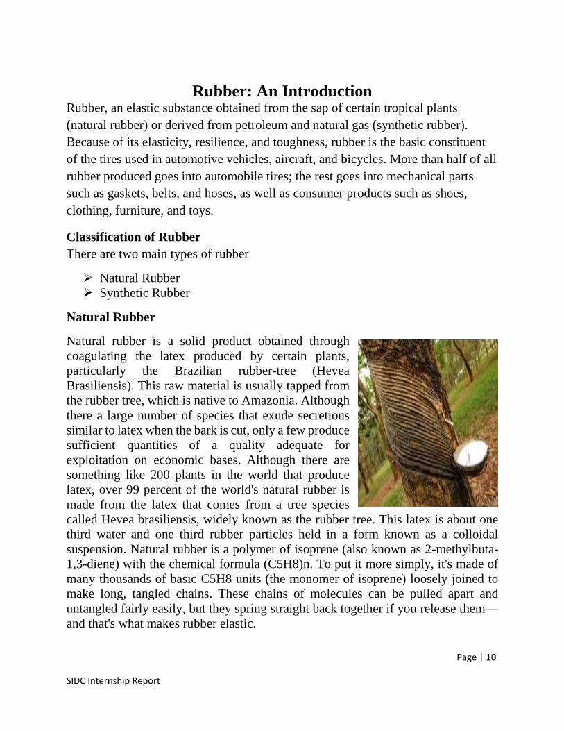
Natural rubber is a solid product obtained throughcoagulating the latex produced by certain plants,particularly the Brazilian rubber-tree (HeveaBrasiliensis). This raw material is usually tapped fromthe rubber tree, which is native to Amazonia. Althoughthere a large number of species that exude secretionssimilar to latex when the bark is cut, only a few producesufficient quantities of a quality adequate forexploitation on economic bases. Although there aresomething like 200 plants in the world that producelatex, over 99 percent of the world's natural rubber ismade from the latex that comes from a tree speciescalled Hevea brasiliensis, widely known as the rubber tree. This latex is about onethird water and one third rubber particles held in a form known as a colloidalsuspension. Natural rubber is a polymer of isoprene (also known as 2-methylbuta-1,3-diene) with the chemical formula (C5H8)n. To put it more simply, it's made ofmany thousands of basic C5H8 units (the monomer of isoprene) loosely joined tomake long, tangled chains. These chains of molecules can be pulled apart anduntangled fairly easily, but they spring straight back together if you release them—and that's what makes rubber elastic.
Page | 11
SIDC Internship Report
Synthetic Rubber
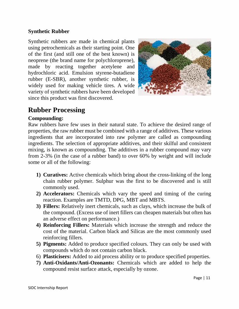
Synthetic rubbers are made in chemical plantsusing petrochemicals as their starting point. Oneof the first (and still one of the best known) isneoprene (the brand name for polychloroprene),made by reacting together acetylene andhydrochloric acid. Emulsion styrene-butadienerubber (E-SBR), another synthetic rubber, iswidely used for making vehicle tires. A widevariety of synthetic rubbers have been developedsince this product was first discovered.
Rubber ProcessingCompounding:Raw rubbers have few uses in their natural state. To achieve the desired range ofproperties, the raw rubber must be combined with a range of additives. These variousingredients that are incorporated into raw polymer are called as compoundingingredients. The selection of appropriate additives, and their skilful and consistentmixing, is known as compounding. The additives in a rubber compound may varyfrom 2-3% (in the case of a rubber band) to over 60% by weight and will includesome or all of the following:
1) Curatives: Active chemicals which bring about the cross-linking of the longchain rubber polymer. Sulphur was the first to be discovered and is stillcommonly used.
2) Accelerators: Chemicals which vary the speed and timing of the curingreaction. Examples are TMTD, DPG, MBT and MBTS.
3) Fillers: Relatively inert chemicals, such as clays, which increase the bulk ofthe compound. (Excess use of inert fillers can cheapen materials but often hasan adverse effect on performance.)
4) Reinforcing Fillers: Materials which increase the strength and reduce thecost of the material. Carbon black and Silicas are the most commonly usedreinforcing fillers.
5) Pigments: Added to produce specified colours. They can only be used withcompounds which do not contain carbon black.
6) Plasticisers: Added to aid process ability or to produce specified properties.7) Anti-Oxidants/Anti-Ozonants: Chemicals which are added to help the
compound resist surface attack, especially by ozone.
Page | 12
SIDC Internship Report
Some Basic Terminologies used in Rubber Industries
Mastication, mixing, shaping, curing, vulcanizing are commonly heard terms inrubber processing industries. Following is the detailed information of this terms
1) MasticationIt is the process of breaking down long molecular chains of rubber like polymers toreduce the viscosity of polymer up to the level where other ingredients may be addedeasily. Mastication and softening are usually carried out in batches. The operation isdone either in large enclosed mixing machines or on rubber mills. The prominentexample of an enclosed machine is the Banbury mixer.
2) MixingMixing can be defined as the process of blending various compounding ingredientsof heterogeneous nature and make the combination into homogeneous nature. Thisis achieved either by an internal mixer, where the compound is mixed by twomeshing rotors in an enclosed case; or by open mill mixing, adding the ingredientscarefully into the “nip” between two steel rollers. The result of either process is abatch of uncured rubber compound.
3) ShapingShaping of the mixture into the desired form takes place in several ways. Extrudersare used to produce long continuous products such as tubing, tire treads, and wirecoverings. They are also used to produce various profiles that can later be cut tolength. Four roll calendars are used to make sheets of desired thickness as in case ofbladder forming.
4) Curing/VulcanizingCuring is carried out in pressurized steel molds, which are heated by steam orelectricity to temperatures at which the interlinking reaction takes place. Typicalcure conditions are several minutes at a temperature of 160 °C and 1 MPa pressure.Because heat penetrates rubber slowly, thick articles must be allowed longer curingtimes, up to several hours, at lower temperatures. Other methods of curing the rubbermix after it has been shaped include steam heating in autoclaves, microwaveirradiation, and passage through a heated bath of molten metal salts or a fluidizedbed. In these cases curing is carried out at near atmospheric pressure.
Page | 13
SIDC Internship Report
A Brief Description of Chemicals used in SIDC Processing Centre
I. Fillers
Stearic AcidIt is also called Rubber Grade. It is a solution of 35% stearic, 50% palmitic acid, 9%oleic acid and 7% miscellaneous saturated compounds. It is used as dispersing agentand accelerator activator in rubber compounds. It facilitates dispersion of pigmentsand fillers and improve processing. It facilitate mold flow and is commonly addedto raw rubber to prevent it from hardness. Its ratio is set to 1% i.e. 100g in 1 kgrubber batch.
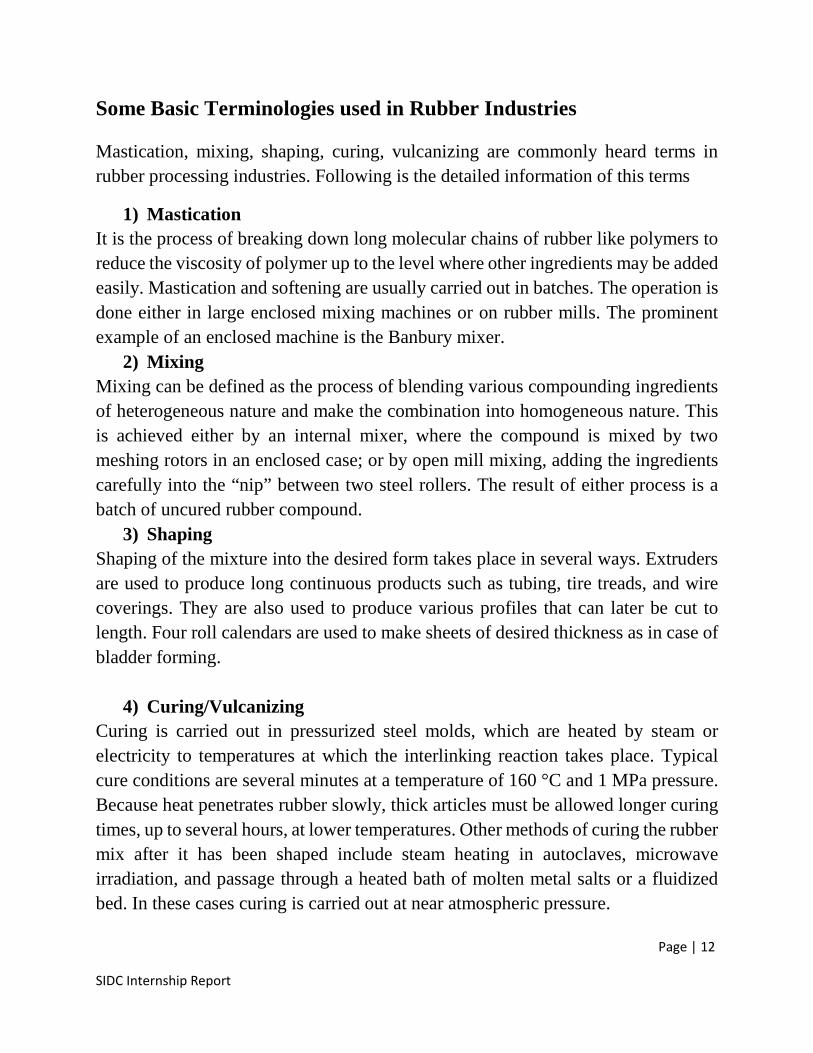
Carbon BlackIt is one of the fillers used in rubber processingindustries. It imparts special strength to rubbercompounds and avoid them from wear andtear also it give blackish colour to rubbercompounds. It is available in various gradesaccording to pour size standard but N330 andN550 are used in SIDC.
CCRCalcium Carbonate Refined is also one of the fillers used in rubber processing. Itimparts strength to rubber compounds and provide extra fineness to their surface.Moreover it also helps in maintaining the weight of rubber compounds and prove tobe economical. That is why it is added in higher percentage i.e. 200%, means 2kg in1 kg of rubber batch.
II. Activator
Zinc OxideIt is used as an activator which bring about the cross-linking of the long chain rubberpolymer and enhances the active site of rubber to take part in reaction effectively. Itis added 0.1% i.e. 1g in I kg rubber batch.
Page | 14
SIDC Internship Report
III. Accelerators
MBTIts chemical name is 2-mercapto benzothiazole. It is one of the commonly usedaccelerators used in rubber processing and act as Sulphur donors to boost up thecross linking of long polymer rubber chains. It is added 1g in 1 kg rubber batch.
MBTSChemically called 2,2-Dithiobis(benzothiazole). It helps in aiding vulcanization andact as Sulphur donor. It is also added 1g in 1kg rubber batch. Generally added toboost up rubber polymer chain cross linking.
IV. Rubber Sprayed Powder
VulkasilIt is a white amorphous powder and is chemically called reinforced precipitatedsilica. It does not allow rubber sheets to stick together and imparts strength to rubbercompounds when sparkled.
V. Glue Paste
Latex GlueIt is a milky exudate from certain plants that coagulates on exposure to air. It act asa glue and helps in binding rubber panels and sheets together firmly. It is used as asolution of 50% latex and 50% water.
Page | 15
SIDC Internship Report
Boiler Section
Boilers are pressure vessels designed to heat water or produce steam, which can thenbe used to provide space heating or service water heating to a building. In mostcommercial building heating applications, the heating source in the boiler is a naturalgas fired burner. Oil fired burners and electric resistance heaters can be used as well.Steam is preferred over hot water in some applications, including absorption cooling,kitchens, laundries, sterilizers, and steam driven equipment.
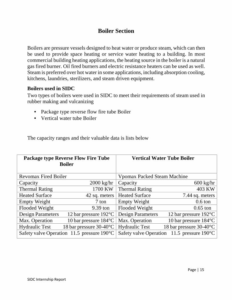
Boilers used in SIDCTwo types of boilers were used in SIDC to meet their requirements of steam used inrubber making and vulcanizing
Package type reverse flow fire tube Boiler Vertical water tube Boiler
The capacity ranges and their valuable data is lists below
Package type Reverse Flow Fire TubeBoiler
Vertical Water Tube Boiler
Revomax Fired Boiler Vpomax Packed Steam MachineCapacity 2000 kg/hr Capacity 600 kg/hrThermal Rating 1700 KW Thermal Rating 403 KWHeated Surface 42 sq. meters Heated Surface 7.44 sq. metersEmpty Weight 7 ton Empty Weight 0.6 tonFlooded Weight 9.39 ton Flooded Weight 0.65 tonDesign Parameters 12 bar pressure 192°C Design Parameters 12 bar pressure 192°CMax. Operation 10 bar pressure 184°C Max. Operation 10 bar pressure 184°CHydraulic Test 18 bar pressure 30-40°C Hydraulic Test 18 bar pressure 30-40°CSafety valve Operation 11.5 pressure 190°C Safety valve Operation 11.5 pressure 190°C
Page | 16
SIDC Internship Report
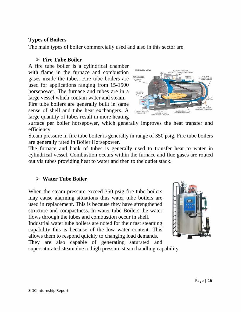
Types of BoilersThe main types of boiler commercially used and also in this sector are
Fire Tube BoilerA fire tube boiler is a cylindrical chamberwith flame in the furnace and combustiongases inside the tubes. Fire tube boilers areused for applications ranging from 15-1500horsepower. The furnace and tubes are in alarge vessel which contain water and steam.Fire tube boilers are generally built in samesense of shell and tube heat exchangers. Alarge quantity of tubes result in more heatingsurface per boiler horsepower, which generally improves the heat transfer andefficiency.Steam pressure in fire tube boiler is generally in range of 350 psig. Fire tube boilersare generally rated in Boiler Horsepower.The furnace and bank of tubes is generally used to transfer heat to water incylindrical vessel. Combustion occurs within the furnace and flue gases are routedout via tubes providing heat to water and then to the outlet stack.
Water Tube Boiler
When the steam pressure exceed 350 psig fire tube boilersmay cause alarming situations thus water tube boilers areused in replacement. This is because they have strengthenedstructure and compactness. In water tube Boilers the waterflows through the tubes and combustion occur in shell.Industrial water tube boilers are noted for their fast steamingcapability this is because of the low water content. Thisallows them to respond quickly to changing load demands.They are also capable of generating saturated andsupersaturated steam due to high pressure steam handling capability.
Page | 17
SIDC Internship Report
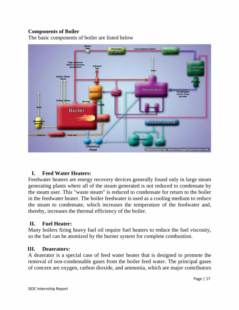
Components of BoilerThe basic components of boiler are listed below
I. Feed Water Heaters:Feedwater heaters are energy recovery devices generally found only in large steamgenerating plants where all of the steam generated is not reduced to condensate bythe steam user. This "waste steam" is reduced to condensate for return to the boilerin the feedwater heater. The boiler feedwater is used as a cooling medium to reducethe steam to condensate, which increases the temperature of the feedwater and,thereby, increases the thermal efficiency of the boiler.
II. Fuel Heater:Many boilers firing heavy fuel oil require fuel heaters to reduce the fuel viscosity,so the fuel can be atomized by the burner system for complete combustion.
III. Deaerators:A deaerator is a special case of feed water heater that is designed to promote theremoval of non-condensable gases from the boiler feed water. The principal gasesof concern are oxygen, carbon dioxide, and ammonia, which are major contributors
Page | 18
SIDC Internship Report
to boilers, and steam and condensate piping corrosion problems. In small steamplants, a portion of the steam generated by the boiler is used to operate the deaeratorif "waste steam" is not available. Failure to maintain and properly operate thedeaerator can lead to early failure of the boiler, steam using equipment, and the steamand condensate piping.
IV. Pumps:In most hot water systems, the system circulating pumps are electric motor-driven,end suction centrifugal pumps. In steam systems, the condensate return pumps aretypically electric motor-driven, end suction, centrifugal or turbine-type pumps. Feedwater pumps are generally electric motor-driven, multiple-stage, end suctioncentrifugal pumps. The shutoff head of the pump must be greater than the steam orhot water system operating pressure.
V. Combustion Air Blowers:In many packaged boiler installations, the combustion air fan is designed andprovided by the boiler manufacturer and is integral with the boiler housing. Ininstallations where a stand-alone fan is provided, low-pressure centrifugal blowersare commonly used. An important characteristic of the blower is the ability tomaintain a relatively constant air pressure over a wide range of airflows.
VI. Flue:Flues (boiler firebox exhaust duct or boiler discharge stack) must be large enough toconduct the products of combustion away from the boiler with a minimum of ductfriction loss. Flues may be fabricated from any material suitable for the operatingtemperature and pressure. Common materials of construction associated withpackaged boiler installations are carbon steel and stainless steel.
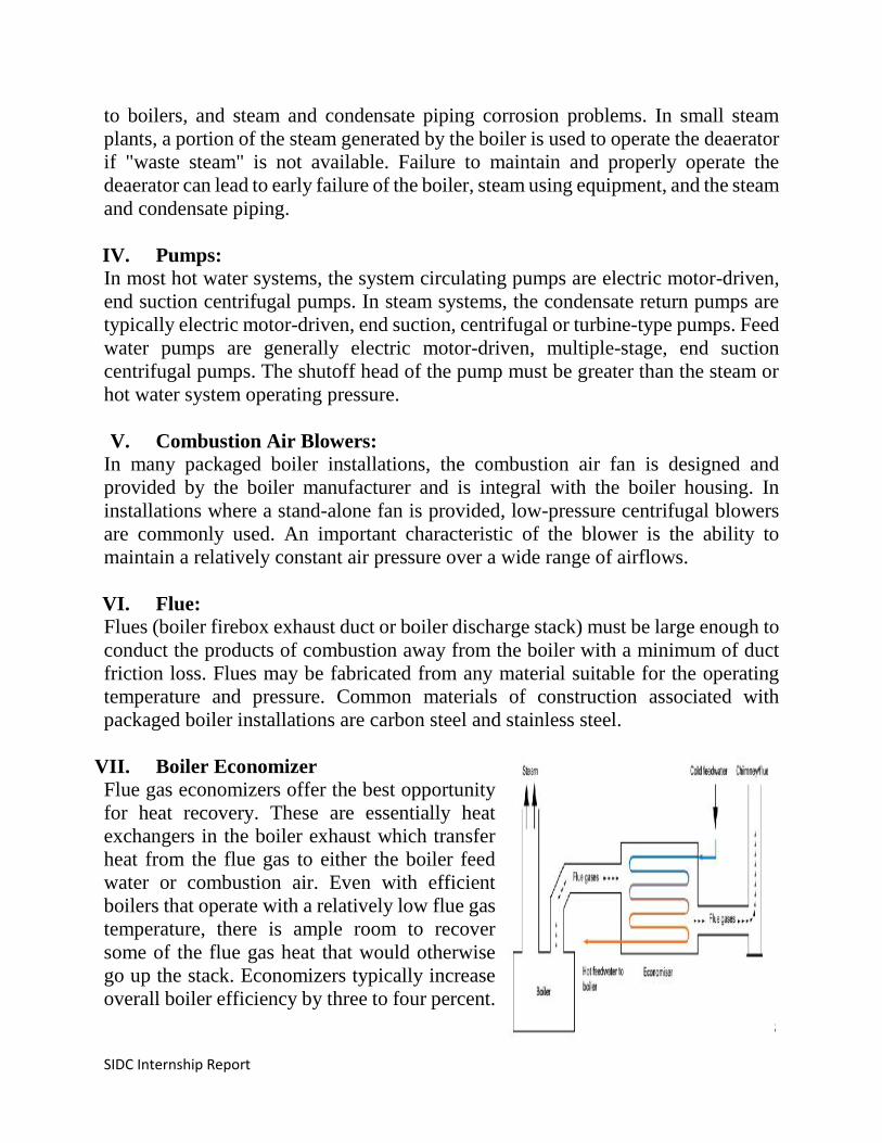
VII. Boiler EconomizerFlue gas economizers offer the best opportunityfor heat recovery. These are essentially heatexchangers in the boiler exhaust which transferheat from the flue gas to either the boiler feedwater or combustion air. Even with efficientboilers that operate with a relatively low flue gastemperature, there is ample room to recoversome of the flue gas heat that would otherwisego up the stack. Economizers typically increaseoverall boiler efficiency by three to four percent.

Page | 19
SIDC Internship Report
Condensing economizers use the same principle, but further reduce the flue-gastemperature, which improves the boiler system efficiency further.
VIII. Steam Traps:Steam traps are installed throughout steam systems to remove condensate (spentsteam), air, and non-condensable gases from the steam system. There are five typesof steam traps in general use now a days.
IX. Boiler Blowdown:Blowdown of steam boilers is very often a highly neglected or abused aspect ofroutine boiler room maintenance. The purpose of boiler blowdown is to controlsolids in the boiler water. Blowdown protects boiler surfaces from severe scaling orcorrosion problems that can result otherwise.
There are two types of boiler blowdowns: ''continuous'' and ''manual''.a) Continuous blowdown uses a calibrated valve and a blowdown tap near the
boiler water surface. As the name implies, it continuously takes water fromthe top of the boiler at a predetermined rate. A continuous blowdown is anoptional feature and may not be included on your steam boiler; however, allsteam boilers should include a means for manual blowdown as standardequipment.
b) Manual blowdowns are accomplished through tapings at the bottom of theboiler. These openings allow for the removal of solids that settle at the bottomof the boiler. Manual blowdown is also used to keep water level controldevices and cutoffs clean of any solids that would interfere with theiroperation. All steam boilers require manual blowdown whether or not theyare supplied with continuous blowdowns.
Boiler WorkingBoth gas and oil fired boilers use controlled combustion of the fuel to heat water.The burner mixes the fuel and oxygen together and, with the assistance of an ignitiondevice, provides a platform for combustion. This combustion takes place in thecombustion chamber, and the heat that it generates is transferred to the water throughthe heat exchanger. Controls regulate the ignition, burner firing rate, fuel supply, airsupply, exhaust draft, water temperature, steam pressure, and boiler pressure. Hotwater produced by a boiler is pumped through pipes and delivered to equipmentthroughout the building, which can include hot water coils in air handling units,service hot water heating equipment, and terminal units. Steam boilers produce
Page | 20
SIDC Internship Report
steam that flows through pipes from areas of high pressure to areas of low pressure,unaided by an external energy source such as a pump. Steam utilized for heating canbe directly utilized by steam using equipment or can provide heat through a heatexchanger that supplies hot water to the equipment.
Safety Remedy for Boiler UseBoiler is one of the critical equipment of process industries so its maintenance andsafety must be the first priority to avoid any technical and human loss.
Monitor the Boiler GaugesIt is possible that a leak will develop in the hot water distribution loop. Such leakswill increase the system’s energy and water consumption, and may also result inwater damage. Hot water and steam distribution systems should be provided withmake-up water to replace any steam or water that is lost through a leak in the system.This will provide an easy way to ensure the system is fully charged with water at alltimes. It is best practice to install a meter on the make-up line to the system. Themeter should be read weekly to check for unexpected losses of water from thesystem. In steam systems, it is a best practice to monitor make-up water volumedaily. As steam leaks from the system, additional make-up water is required toreplace the loss. Monitoring the make-up water will ensure that you are maximizingthe return of condensate, thereby reducing the need for make-up water.
Seasonal OperationIf a steam or hot water system is not used for a portion of the year, shutting thesystem down can result in significant savings. Maintaining a boiler at its operatingtemperature consumes energy equivalent to its standby losses. In the case of a hotwater system, energy use may also include pump operation.
Keep the Boiler cleanAny residue, such as soot or scale that coats the heat transfer surfaces of the boilerwill reduce its efficiency and also increase the likelihood of equipment failure.Cleaning this surface according to manufacturer’s recommendations is important tomaintaining optimum boiler performance and equipment life. Residue that coats thetubes of a boiler will interfere with heat transfer and elevate the flue gas temperature.If incomplete combustion occurs, the resulting soot accumulates on the combustionside of the tubes. Similarly, poor water treatment practices can result in scaleaccumulation on the water side of the tubes. A layer of soot or scale only 0.03 inchesthick can reduce heat transfer by 9.5%. A layer 0.18 inches thick can reduce heattransfer by 69%.
Page | 21
SIDC Internship Report
Minimize boiler BlowdownHaving too many total dissolved solids (TDS’s) in the boiler water can cause scaleand reduce boiler efficiency. Therefore, it is necessary to maintain the solids belowcertain limits. As TDS concentration increases, it becomes more likely that thedissolved solids will precipitate out of the water and form scale. Draining of thewater, called boiler blowdown, is required to remove some of those dissolved solidsand keep the TDS concentration below the level where they will precipitate.Consistent and frequent small volume blowdowns is a better practice than infrequenthigh volume blowdowns, because it conserves energy, water, and chemicals.
Inspect and Repair InsulationInsulation is critical for steam and condensate piping. Un-insulated pipes, valves, orfittings carry a heavy energy penalty Steam, condensate, and hot water pipes in airconditioned spaces produce a double penalty if un-insulated because the heat lossfrom the pipes must be removed by additional air conditioning.
Use of Boiler in SIDCSteam produced by boilers used in SIDC is saturated steam which is used in varioussteps of rubber to football making process.
Steam is used to heat up the rolls of two roll mixer, 4 roll calendar and kneadermixer to soften the batch of rubber so that it can easily be processed. The settemperature of rolls in two roll mixer is 4.-50°C whereas in four roll calendarand kneader mixer is between 80-90°C.
In rubber curing section steam is used to heat the curing machine to 160°C tomake neat joints of rubber pieces together.
In die cut bladder machine the steam generated is used to heat up the die thatwill afterwards make the mold of rubber. Temperature set to this machine is60-70°C.
In auto laminated machine where two halves of football are joint together withbladder inside and football attains its complete shape, steam is used to heat upthe die to 160°C so that strong joints may be formed between two halves.
Page | 22
SIDC Internship Report
Water Treatment of Boiler Feed WaterWater is an excellent solvent in which many compounds readily dissolve. It is alsoan excellent medium for transporting suspended and colloidal material. However,the presence of these impurities and contaminants makes appropriate water treatmentand conditioning regimes essential to provide water of a suitable quality for theeffective operation of steam boiler plant and systems.The water used in steam boilers can be supplied from many different sources andwill contain various contaminants and impurities. If water is used directly in steamboilers without treatment, then these contaminants and impurities can cause foulingof heat-transfer surfaces and corrosion, leading ultimately to plant failure.
Hard WaterHard water is water that contains more dissolved minerals than ordinary water. Hardwater contains mainly calcium and magnesium salts and these result in scaleformation.
Soft WaterSoft water is preferable for use in boiler plant because it has fewer dissolved solids,so it needs less treatment.
Effects of using Untreated Hard WaterFoaming, due to high levels of total dissolved solids (TDS) and alkalinity in theboiler water, can also cause operational problems, such as salt deposits and pipeworkcorrosion.Poor water treatment and boiler-water conditioning can:• Reduce the steam-generating efficiency of boiler plant through fouling ofwater-side, heat-transfer surfaces and increased blowdown.• Increase the cost of routine boiler cleaning operations (chemical andmechanical) and the need to repair/replace corroded parts.• Result in carry over and reduced heat delivered to components using thesteam system.• Result in catastrophic plant failure if sustained over a significant period
Page | 23
SIDC Internship Report
Types of water treatmentWater treatment is generally divided into two forms:
• External treatment – applied before the water enters the boiler to remove ormodify problem mineral salts. SP 502 (a neutralizer) was used in SIDC boiler feedwater tank which donot allow scale to build up, moreover tri sodium phosphate andtactic acid were used which remove scaling and donot allow scale to stick to thetubes respectively.• Internal treatment (sometimes referred to as boiler water conditioning) –chemicals are added directly to the feed or boiler water to prevent scale formationand corrosion.
Water Softening Mechanism
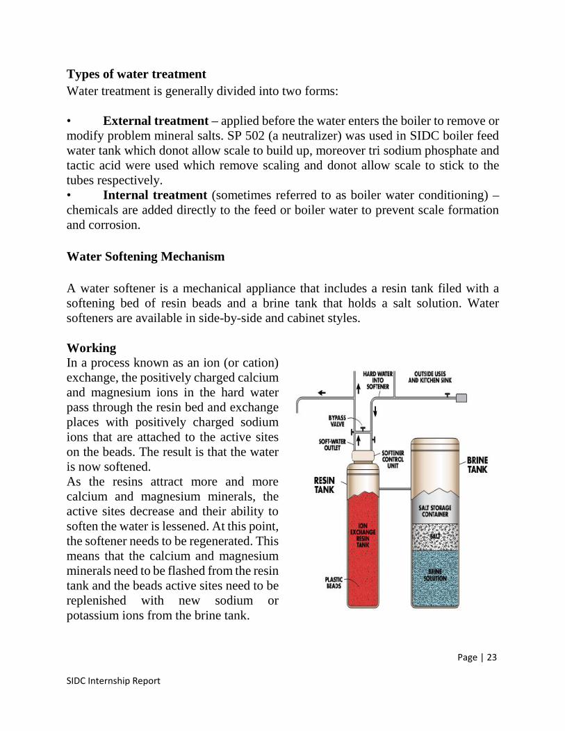
A water softener is a mechanical appliance that includes a resin tank filed with asoftening bed of resin beads and a brine tank that holds a salt solution. Watersofteners are available in side-by-side and cabinet styles.
WorkingIn a process known as an ion (or cation)exchange, the positively charged calciumand magnesium ions in the hard waterpass through the resin bed and exchangeplaces with positively charged sodiumions that are attached to the active siteson the beads. The result is that the wateris now softened.As the resins attract more and morecalcium and magnesium minerals, theactive sites decrease and their ability tosoften the water is lessened. At this point,the softener needs to be regenerated. Thismeans that the calcium and magnesiumminerals need to be flashed from the resintank and the beads active sites need to bereplenished with new sodium orpotassium ions from the brine tank.
Page | 24
SIDC Internship Report
Resin Bed Regeneration
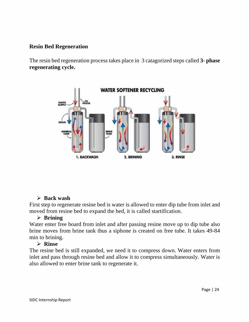
The resin bed regeneration process takes place in 3 catagorized steps called 3- phaseregenerating cycle.
Back washFirst step to regenerate resine bed is water is allowed to enter dip tube from inlet andmoved from resine bed to expand the bed, it is called startification. Brining
Water enter free board from inlet and after passing resine move up to dip tube alsobrine moves from brine tank thus a siphone is created on free tube. It takes 49-84min to brining. Rinse
The resine bed is still expanded, we need it to compress down. Water enters frominlet and pass through resine bed and allow it to compress simultaneously. Water isalso allowed to enter brine tank to regenerate it.
Page | 25
SIDC Internship Report
Compressor Room
Compressed air is a form of power that has many important uses in industrialactivities. Air compressor plants are used to provide an adequate quantity ofcompressed air at sufficient pressure to various points of application. Industrialplants use compressed air throughout their production operations, which is producedby compressed air units ranging from 5 horsepower (hp) to over 50,000 hp.
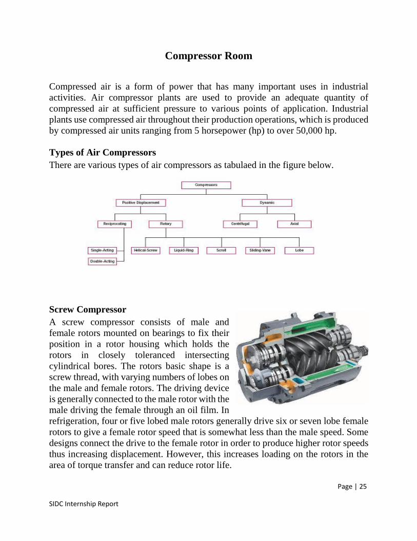
Types of Air CompressorsThere are various types of air compressors as tabulaed in the figure below.
Screw CompressorA screw compressor consists of male andfemale rotors mounted on bearings to fix theirposition in a rotor housing which holds therotors in closely toleranced intersectingcylindrical bores. The rotors basic shape is ascrew thread, with varying numbers of lobes onthe male and female rotors. The driving deviceis generally connected to the male rotor with themale driving the female through an oil film. Inrefrigeration, four or five lobed male rotors generally drive six or seven lobe femalerotors to give a female rotor speed that is somewhat less than the male speed. Somedesigns connect the drive to the female rotor in order to produce higher rotor speedsthus increasing displacement. However, this increases loading on the rotors in thearea of torque transfer and can reduce rotor life.
Page | 26
SIDC Internship Report
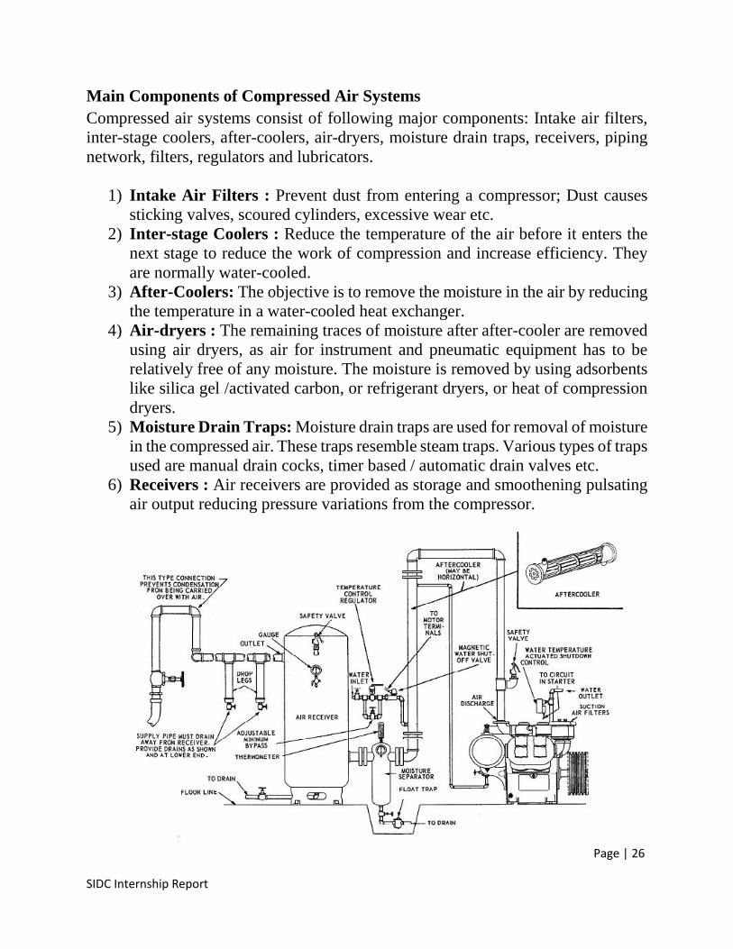
Main Components of Compressed Air SystemsCompressed air systems consist of following major components: Intake air filters,inter-stage coolers, after-coolers, air-dryers, moisture drain traps, receivers, pipingnetwork, filters, regulators and lubricators.
1) Intake Air Filters : Prevent dust from entering a compressor; Dust causessticking valves, scoured cylinders, excessive wear etc.
2) Inter-stage Coolers : Reduce the temperature of the air before it enters thenext stage to reduce the work of compression and increase efficiency. Theyare normally water-cooled.
3) After-Coolers: The objective is to remove the moisture in the air by reducingthe temperature in a water-cooled heat exchanger.
4) Air-dryers : The remaining traces of moisture after after-cooler are removedusing air dryers, as air for instrument and pneumatic equipment has to berelatively free of any moisture. The moisture is removed by using adsorbentslike silica gel /activated carbon, or refrigerant dryers, or heat of compressiondryers.
5) Moisture Drain Traps: Moisture drain traps are used for removal of moisturein the compressed air. These traps resemble steam traps. Various types of trapsused are manual drain cocks, timer based / automatic drain valves etc.
6) Receivers : Air receivers are provided as storage and smoothening pulsatingair output reducing pressure variations from the compressor.
Page | 27
SIDC Internship Report
Brief Description of Compression System Components
1) SilencersCompressor system silencers are sound-absorbing accessories attached to the systemat the intake and output of the compressor.The silencers absorb noise produced by thecompressor in order to reduce the noise outputto an acceptable level. In general, air noisesilencers are cylindrical housings containingacoustically tuned baffles and sound-absorbing material.
2) SeparatorsSeparators are used on compressor installations to remove entrained water and oilfrom the compressed air.There are two types of separators Centrifugal Separator Baffle Separator
In centrifugal separators, Centrifugal action forces the moisture particles againstthe wall of the separator where they drain to the bottom. In the baffle type separatorthe air is subjected to a series of sudden changes in direction. The heavier moistureparticles strike the baffles and walls of the separator and drain to the bottom of theunit.
Page | 28
SIDC Internship Report
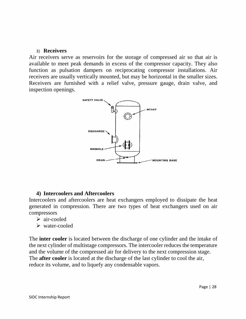
3) ReceiversAir receivers serve as reservoirs for the storage of compressed air so that air isavailable to meet peak demands in excess of the compressor capacity. They alsofunction as pulsation dampers on reciprocating compressor installations. Airreceivers are usually vertically mounted, but may be horizontal in the smaller sizes.Receivers are furnished with a relief valve, pressure gauge, drain valve, andinspection openings.
4) Intercoolers and AftercoolersIntercoolers and aftercoolers are heat exchangers employed to dissipate the heatgenerated in compression. There are two types of heat exchangers used on aircompressors air-cooled water-cooled
The inter cooler is located between the discharge of one cylinder and the intake ofthe next cylinder of multistage compressors. The intercooler reduces the temperatureand the volume of the compressed air for delivery to the next compression stage.The after cooler is located at the discharge of the last cylinder to cool the air,reduce its volume, and to liquefy any condensable vapors.
Page | 29
SIDC Internship Report
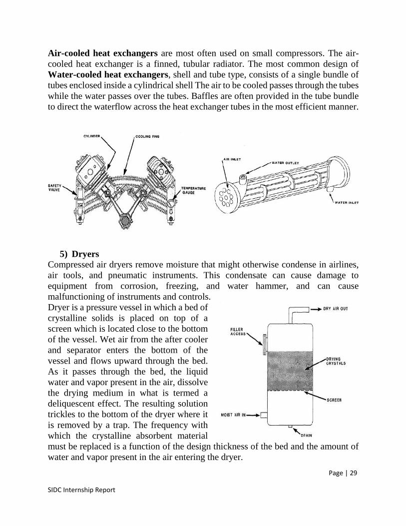
Air-cooled heat exchangers are most often used on small compressors. The air-cooled heat exchanger is a finned, tubular radiator. The most common design ofWater-cooled heat exchangers, shell and tube type, consists of a single bundle oftubes enclosed inside a cylindrical shell The air to be cooled passes through the tubeswhile the water passes over the tubes. Baffles are often provided in the tube bundleto direct the waterflow across the heat exchanger tubes in the most efficient manner.
5) DryersCompressed air dryers remove moisture that might otherwise condense in airlines,air tools, and pneumatic instruments. This condensate can cause damage toequipment from corrosion, freezing, and water hammer, and can causemalfunctioning of instruments and controls.Dryer is a pressure vessel in which a bed ofcrystalline solids is placed on top of ascreen which is located close to the bottomof the vessel. Wet air from the after coolerand separator enters the bottom of thevessel and flows upward through the bed.As it passes through the bed, the liquidwater and vapor present in the air, dissolvethe drying medium in what is termed adeliquescent effect. The resulting solutiontrickles to the bottom of the dryer where itis removed by a trap. The frequency withwhich the crystalline absorbent materialmust be replaced is a function of the design thickness of the bed and the amount ofwater and vapor present in the air entering the dryer.
Page | 30
SIDC Internship Report
Safety Remedy for Use of Air Compression System
Good and proper maintenance practices will dramatically improve the performanceefficiency of a compressor system. Following are a few tips for efficient operationand maintenance of industrial compressed air systems:
1. Lubrication: Compressor oil pressure should be visually checked daily, andthe oil filter changed monthly.
2. Air Filters: The inlet air filter can easily become clogged, particularly industy environments. Filters should be checked and replaced regularly.
3. Condensate Traps: Many systems have condensate traps togather and (forthose traps fitted with a float operated valve) flush condensate from thesystem. Manual traps should be periodically opened and re-closed to drain anyaccumulated fluid; automatic traps should be checked to verify they are notleaking compressed air.
4. Air Dryers: Drying air is energy-intensive. For dryers, inspect and replacepre filters regularly as these dryers often have small internal passages that canbecome plugged with contaminants. Dryers require an effective oil-removalfilter on their inlets, as they will not function well if lubricating oil from thecompressor coats the desiccant. The temperature of deliquescent dryersshould be kept below 100°F to avoid increased consumption of the desiccantmaterial, which should be replenished every 3-4 months depending on the rateof depletion.
Use of Air Compression System in SIDCThe use of compressed air in SIDC can be analyzed by following facts
The bladder and football are inflated using compressed air. Much of the machinery is pneumatic i.e. panel cutting machine, hole punching
machine, tikra press etc. Almost all machines have pistons and plungers i.e. curing machine,
vulcanizing machine, kneader mixer etc. that are either pneumatic orhydraulic.
Page | 31
SIDC Internship Report
Bladder SectionThe bladder section of SIDC comprises of various pneumatic, hydraulic, electropneumatic, steam and electric heater machines which take part somewhere inrubber to bladder production process and are listed below
Raw Rubber Cutter Kneader Machine/Dispersion Mixer Two Roll Mill Four Roller Calendar Powder Spray & Rubber Slice Cutting Machine Valve Hole Punching Machine Pneumatic Valve Seat Stamp Machine Hydraulic Bladder Forming Machine Bladder Vulcanizing Machine Pin Cutting Machine Pin Inserting Machine
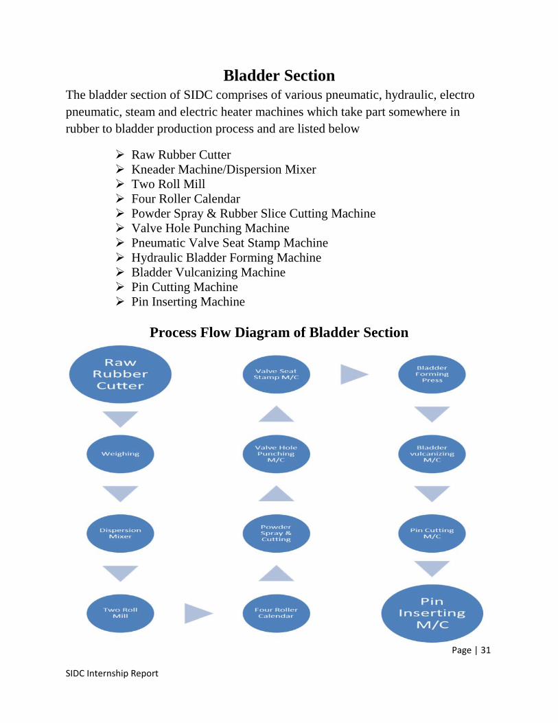
Process Flow Diagram of Bladder Section
Page | 32
SIDC Internship Report
Process Description of Bladder ManufacturingThe Raw rubber is available in the packing of bales so it is necessary to cut the bales;this is done by using Raw Rubber cutter. After the cutting of rubber into pieces theRubber & the other chemicals are weighed as per the formulation.
Working in Mixing RoomThe dispersion mixer is used for mixing after achieving the required temperature byusing steam the weighed chemicals are fed to the dispersion mixer the amount offeeding material begin from half load to full load. According to the material and craftrequirement of consumer the mixing time is adjusted.If the temperature increased beyond the set value an alarm starts indicating & needsthe circulation of cooling water. After completing the mixing the mixing chambertilt at an angle of 140° & the master batch is discharged from the chamber.The master batch from the dispersion mixer is fed to the two roll mill for furthermixing of accelerators etc. The two roll mill is also used for plastication prior tomixing in the dispersion mixer.
Working in Bladder SectionThe final batch prepared at two roll mill is fed to the four roller calendar for sheetingpurpose. The gap of the rollers is adjusted as per the thickness of sheet required.The sheet is rolled to the powder spray & cutting machine it’s a triple action machinei.e. Cooling, powder spray & Cutting, the speed of this machine is synchronized withthe calendar speed.The sheet is cooled via cooling water through cooling roller. The powder is sprayedthrough the powder box & spare powder is cleaned through powder brush. Finallythe desired length of sheet is cut through heated knife cutter.The sheet is transported to the next stage of hole punching. The hole punch machineis used to produce the hole in bladder rubber sheet.After the hole punching the sheet transported to valve seat stamp machine, thismachine is used to stamp-paste a valve onto the bladder sheet. The valve insertedsheet is cut into bladder on bladder forming machine as per the required size.The vulcanization of bladder is done on bladder vulcanization machine. Thismachine adopts steam heating and water cooling. After vulcanization the pin isinserted in the bladder through which the football is inflated.
Page | 33
SIDC Internship Report
Machinery used in Bladder Section & Mixing Room
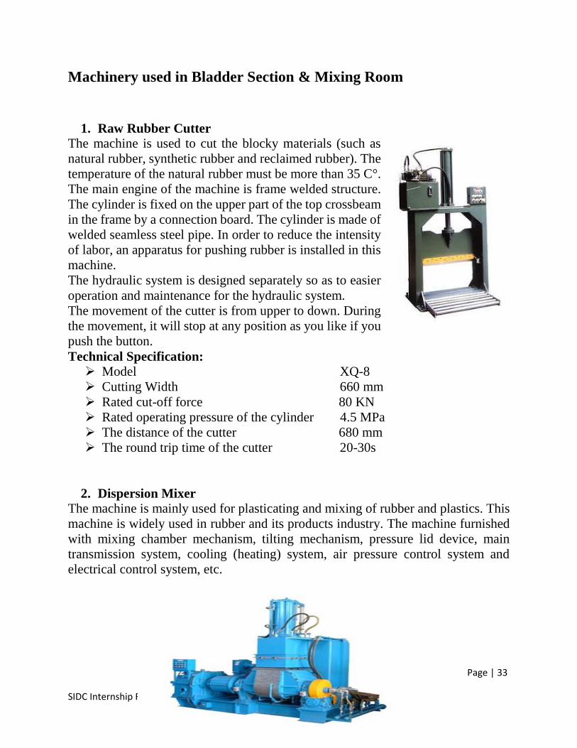
1. Raw Rubber CutterThe machine is used to cut the blocky materials (such asnatural rubber, synthetic rubber and reclaimed rubber). Thetemperature of the natural rubber must be more than 35 C°.The main engine of the machine is frame welded structure.The cylinder is fixed on the upper part of the top crossbeamin the frame by a connection board. The cylinder is made ofwelded seamless steel pipe. In order to reduce the intensityof labor, an apparatus for pushing rubber is installed in thismachine.The hydraulic system is designed separately so as to easieroperation and maintenance for the hydraulic system.The movement of the cutter is from upper to down. Duringthe movement, it will stop at any position as you like if youpush the button.Technical Specification: Model XQ-8 Cutting Width 660 mm Rated cut-off force 80 KN Rated operating pressure of the cylinder 4.5 MPa The distance of the cutter 680 mm The round trip time of the cutter 20-30s
2. Dispersion MixerThe machine is mainly used for plasticating and mixing of rubber and plastics. Thismachine is widely used in rubber and its products industry. The machine furnishedwith mixing chamber mechanism, tilting mechanism, pressure lid device, maintransmission system, cooling (heating) system, air pressure control system andelectrical control system, etc.
Page | 34
SIDC Internship Report
The mixing chamber is mainly working part of the machine, Material of formulationcalculate is fed to closeness mixing chamber from feeding mouth behind themachine, in the case of pressure and limited temperature, through these actives ofmix blend, mixing , squeeze, slice, etc. Motive of rotor comes from main drivingsystem, The top ram moves up or down rectangular slide way which it is fixed upperthe mixing chamber through the piston rod stretch and contract, it is controlled bypneumatic system. The inner of mixing chamber, rotor and top ram are hollowstructure. The cooling & heating water could pass through them, so rubber materialwill be mixed and plasticed under the fit temperature through cooling & heatingwater controlled, so quality of products should be assured. Mixing chamber can tilt140° under the tilting motor driving; it is convenient to automatic discharge andrecharge color.Technical Specification:
Total capacity of mixing chamber 125L Effective capacity of mixing 55 L Rotor speed(Front/Rear) 30/24.5r/min Main motor rate power 75KW Tilting motor rate power 2.2 KW Mixing chamber tilting angle 140° Pressure of compressed air 0.6-0.8MPa Pressure of cooling water 0.2-0.4MPa Pressure of steam 0.5-0.8 MPa Overall dimensions ( L×W×H) 3280×1930×3070mm Weight 7800 Kg
3. Two Roll MillThe machine is to be used for Raw rubber plasticating and mixing, warm-up orsheeting of rubber. It is general equipment in rubber industry.This is a double roll rubber-mixing machine. It consists of motor, reducer, speed-ratio gears, front and rear rolls, bearings, frame, cover, bed plate, roller gap adjustingdevice, emergency stop device, roll temperature adjust device, lubricating deviceand material tray, etc.Front and rear rolls are parallel mounted into the bearing of the machine frame. Bydriven of the motor, via the reducer, speed ratio gears, the front and rear rolls rotatetoward each other so that rubber-mixing is start. The rolls are made from chilled castalloy iron, the structure of the roll is hollowed, can go through steam and coolingwater, to adjust the roller surface temperature. Its surface possesses the higherhardness and fineness. Roll spacing adjusting is carried out by means of the reverseof hand wheel makes the thread rod drive front bearing base movement. The roll pin
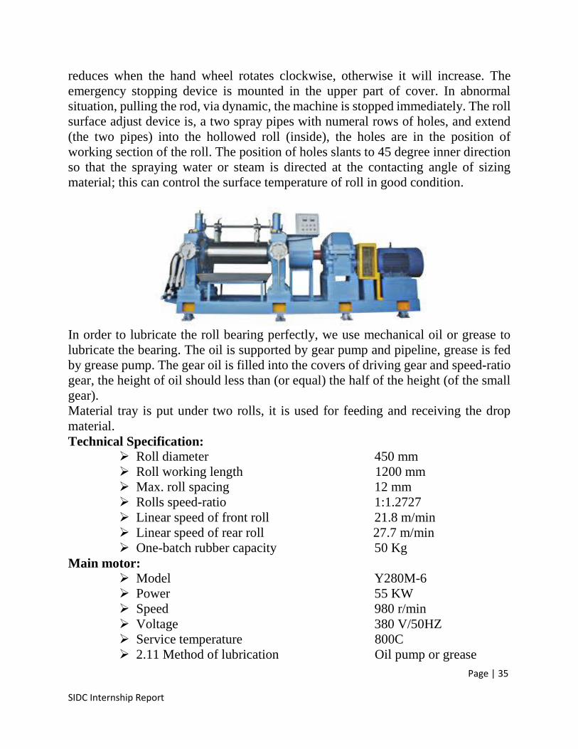
Page | 35
SIDC Internship Report
reduces when the hand wheel rotates clockwise, otherwise it will increase. Theemergency stopping device is mounted in the upper part of cover. In abnormalsituation, pulling the rod, via dynamic, the machine is stopped immediately. The rollsurface adjust device is, a two spray pipes with numeral rows of holes, and extend(the two pipes) into the hollowed roll (inside), the holes are in the position ofworking section of the roll. The position of holes slants to 45 degree inner directionso that the spraying water or steam is directed at the contacting angle of sizingmaterial; this can control the surface temperature of roll in good condition.
In order to lubricate the roll bearing perfectly, we use mechanical oil or grease tolubricate the bearing. The oil is supported by gear pump and pipeline, grease is fedby grease pump. The gear oil is filled into the covers of driving gear and speed-ratiogear, the height of oil should less than (or equal) the half of the height (of the smallgear).Material tray is put under two rolls, it is used for feeding and receiving the dropmaterial.Technical Specification:
Roll diameter 450 mm Roll working length 1200 mm Max. roll spacing 12 mm Rolls speed-ratio 1:1.2727 Linear speed of front roll 21.8 m/min Linear speed of rear roll 27.7 m/min One-batch rubber capacity 50 Kg
Main motor: Model Y280M-6 Power 55 KW Speed 980 r/min Voltage 380 V/50HZ Service temperature 800C 2.11 Method of lubrication Oil pump or grease
Page | 36
SIDC Internship Report
2.12 Overall dimension(L×W×H) 5405×1740×1790mm 2.13 Weight 11400 Kg
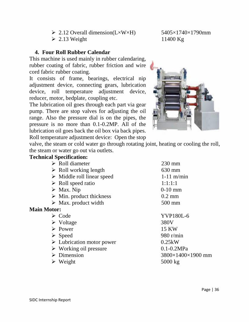
4. Four Roll Rubber CalendarThis machine is used mainly in rubber calendaring,rubber coating of fabric, rubber friction and wirecord fabric rubber coating.It consists of frame, bearings, electrical nipadjustment device, connecting gears, lubricationdevice, roll temperature adjustment device,reducer, motor, bedplate, coupling etc.The lubrication oil goes through each part via gearpump. There are stop valves for adjusting the oilrange. Also the pressure dial is on the pipes, thepressure is no more than 0.1-0.2MP. All of thelubrication oil goes back the oil box via back pipes.Roll temperature adjustment device: Open the stopvalve, the steam or cold water go through rotating joint, heating or cooling the roll,the steam or water go out via outlets.Technical Specification:
Roll diameter 230 mm Roll working length 630 mm Middle roll linear speed 1-11 m/min Roll speed ratio 1:1:1:1 Max. Nip 0-10 mm Min. product thickness 0.2 mm Max. product width 500 mm
Main Motor: Code YVP180L-6 Voltage 380V Power 15 KW Speed 980 r/min Lubrication motor power 0.25kW Working oil pressure 0.1-0.2MPa Dimension 3800×1400×1900 mm Weight 5000 kg
Page | 37
SIDC Internship Report
5. Powder Spray & Cutting MachineThe final sheet from the calendar is transported to the powder spray & cutting unit.This machine has three functions i.e. cooling, powder spray & cutting. The rubbersheet is cooled down via cooling water and after that powder is sprayed on the sheetby passing the sheet through a powder box, the extra powder is wiped through thebrushes. At the end, the sheet is cut as per the required length through the blade, theblade has auxiliary heating for easy & convenient operation.Technical Specification:
Motor Power 1.65 KW Heating Power 700 W Dimension 3650x1200x1300 mm
6. Valve Hole Punch MachineThe machine is used to produce hole in bladder rubber sheet (Natural Rubber,Synthetic Rubber & reclaimed Rubber). The hole then accommodates valve seat inthem. The temperature of the natural rubber based bladder sheet must be at ambienttemperature.The operation of this machine is fully pneumatic. In order to operate the machinefirst of all open the instrument air to energize the machine & check the pressure ofinstrument air is between 0.15 to 0.8 MPa. Put the bladder rubber sheets beneath theplunger and press the push button, keep the button pressed until the plunger isthrough the sheet, duration of pressing the button depends on the number of sheets.More sheets more will be the duration.Technical Specification:
Type WX-2 Serial No. 0138103 Contour dimension 1500X500X800 mm Plunger hole punch dia. 15 mm Operating pressure of plunger 0.15~08 MPa Weight 180 kg
7. Pneumatic Valve Seat stamp MachineThis machine is used to stamp-paste a valve into the bladder sheet that has alreadybeen through from the valve hole punch machine concentrically. The seat thenaccommodates the nozzle through which the football is inflated. The machine iswelded to a bed/table. There are six working stations on a bed. The operation ofmachine is electro-pneumatic.First of all instrument air is opened to energize the machine, the pressure should bein between 0.15 to 0.80 MPa. The bladder sheets that are through from the hole
Page | 38
SIDC Internship Report
punch machine are placed concentrically beneath the plunger and then put valve ontothe bladder sheet. Put both hands on the push buttons and press them simultaneously.Keep the button pressed until the plunger stamps the seats well on the sheets.Duration of pressing the button will depend upon the quality of stamping ifunsatisfied; repeat the procedure with a longer duration.
Technical Specification: Contour dimension 2500x453x855 mm Plunger valve seat stem diameter 18 mm Operating pressure of plunger 0.15~0.8 MPa Weight 310 kg Electrical consumption 0.1 KW
8. Bladder Forming MachineThis machine is used to cut the raw bladder from the rubber sheet. The machineadopts hydraulic transmission, and four column structure, good guidance, oilcylinder installed on the platform, hydraulic pump adopts double pump structure.Uses the low pressure large flow and high pressure small flow pump, combiningaction quickly. Hot plate temperature is controlled by electric heating. The sheet isfolded as per the folding method of the knife mold, press the start button. The sheetwill be cut into hollow rubber bladder.Technical Specification:
Oil pump pressure 8-12 Mpa Heating power 2KW Dimension 1500x1350x1550 mm Weight 1050 Kg
9. Bladder Vulcanizing MachinePneumatic carcass vulcanization machine is used for vulcanization of rubber balland carcass.This machine adopts steam heating and water cooling, heating process is soft,uniform temperature distribution, good curing effect. The mechanical transmission,simple structure, reliable operation, high degree of automation.Put bladder into the mold ( molds are opening, press the clamping button on thestation, so the electric solenoid valve, compressed air into the main the upper end ofthe cylinder, the piston descends, driven by the upper mold clamping immediately.Compressed air goes to front of the locking cylinder. A lever is driven to motivatethe rotation of locking pin to lock up the cylinder. In the mean time travelling switchis motivated, vulcanization timing is recorded. Bladder starts to exhaust and
Page | 39
SIDC Internship Report
countdown exhausting time. Unlock the locking pin, the main cylinder goes up whentime is up, opening the molds. Each position repeats the same procedure.Technical Specification:
Air Pressure 0.5-1.6 MPa Steam Pressure 0.4-0.8 MPa Dimension 3400x800x1850 mm Weight 1350 Kg
10.Pin Cutting MachineThe operation process of this machine is as follow;Greater than or equal 0.4 MPa pressure turned the gas source, and make sure thatthere is compressed air in the pipe. Make sure the power indicator is displayedcorrectly. Depress the foot switch, observe the positioning cylinder and cylinder borestab whether to return in situ. When the two cylinder return in situ, adjust the airnozzle which in side of the throttle valve, the air nozzle there is adequate airflow.Depress the foot switch, the machine start working. Work is completed lift the footswitch. Off the air and power supply.
11.Pin Inserting MachinePin inserting machine is used for opening a hole on the air pin for inflation. Thecylinder installed on the bracket, cylinder on the piston rod is equipped with a bluntneedle, needle punching on three sides into edge. Valve core to be included in thelower die, the foot pedal switch, cylinder piston rod drives the blunt needle drop, acut blunt needle to the valve core.Technical Specification:
Air Pressure 0.3-0.6 MPa Dimension 1000x380x1500 mm
Page | 40
SIDC Internship Report
Yarn Winding HallThe standard weight of bladder which come from bladder section is 210-240g andit also depends upon the consumer.After bladder is vulcanized, it is sent to yarn winding section where yarn is warnon the bladder.
Purpose of Yarn WindingThe sole purpose of yarn winding is Not to allow bladder to become DE shaped when inflated To control the size of bladder To impart extra strength to bladder
Yarn Winding MachinePVA 38 yarn is used in SIDC which is winded on bladders to enhance their strengthand sphericity. An electronic machine with gear system is used to wind yarn onbladder. WX-D Coiling machine is used to wind yarn on bladder. Bladder is held ina cup shaped chamber and various rolls rotate the bladder along with winding yarnon it. The set weight of yarn is 30g which is to be winded on bladder.A latex glue is used from which yarn after passing is winded on ball. Latex used inyarn winding hall is a solution of 50% latex and 50% water. This glue help in stickingof yarn together and do not allow the threads to be loosen. The weight of latex isagain set to be 10g to meet the weight standards of ball.Heating conveyors are used to firmly stick glue on bladder winding. Temperature ofthese conveyors is 60-70°C.
Carcass BladderThe completely finished yarn winded bladder is called carcass bladder. It is free fromDE shaping and has improved sphericity and strength.
Now this carcass bladder can be inflated to 0.6 bar air pressure and send to panelcutting room where panels would be sticking on it.
Page | 41
SIDC Internship Report
Panel Cutting Room
The outer look of football i.e. patches of rexin are made and printed in this sectionor we may say that the finished shape of football take place in this section.
1) Football SheetFootball sheet is made from three basic ingredients Rexin Cloth Eva Foam
Rexin is at the top, eva foam at bottom and cloth is sandwich between the two. Thesethree ingredients are stick together by a strong glue solution i.e. 50% latex glue soln.One meter length sheets are made from which patches of 6 footballs would be cutout. The thickness of sheet is maintained at 4.3mm. Eva 3mm, rexin 1mm and clothis 0.3mm.The Eva foam provides shock absorption effect to ball when shooted. Rexin is usedto add charming appearance to ball. The purpose of using cloth in between eva andrexin is that
It provides strength to ball Do not allow ball to wear out Protects Eva foam from damage.
2) Panel Printing MachineAfter sheet is made it is sent for printing various designs on it. A positive is made ofa printed sketch and by using auto screen printer machine or by manual printing,sketches are drawn on ball.
3) High Frequency Embossing MachineA high frequency embossing machine is also available here which is designed toemboss various patterns or tags on the panels. It works on simple principle, a plungeris at the top, the design to be embossed is fed to it, the plunger simply punch thepanel and pattern is embossed on it.Panels are cut in two basic patterns Pentagonal Hexagonal
Page | 42
SIDC Internship Report
Hexa or Penta shaped dies are provided and by using hydraulic cutting press panelsare taken out of the sheet. The ball is designed such that in between 5 hexagonalpanels a pentagonal panel is adjusted. It helps in providing Roundness to ball Strength to ball
4) Edge Turning MachineAfter the panels are cut out they are flat and cannot be put in operation until andunless they are made curved and their edges are turned. This is done via Panelturning machine. The angle of turned edges is set to be 80-90°. A panel shaped dieis provided in machine and a high pressure plunger presses panel down so the desiredshape is achieved.
5) Auto lamination MachineThe panels of ball are stick together using latex glue. Two halves of football aremade from panel. These two halves are placed in auto laminated machine withcarcass bladder inside them. It is then baked at 160°C for 2-3 min, suction is providedinside the die which allow the two halves to stick together firmly and at last finalfootball is made.
The final football must have the weight of 420-440 g.
Page | 43
SIDC Internship Report
Basket Ball Manufacturing
IntroductionThe ball is spherical in shape and is inflated. Basket-balls range in size from 28.5-30 in (72-76 cm) in circumference, and in weight from 18-22 oz (510-624 g). Forplayers below the high school level, a smaller ball is used, but the ball in men's gamesmeasures 29.5-30 in (75-76 cm) in circumference, and a women's ball is 28.5-29 in(72-74 cm) in circumference. The covering of the ball is leather, rubber,composition, or synthetic, although leather covers only are dictated by rules forcollege play, unless the teams agree otherwise. Orange is the regulation color. At alllevels of play, the home team provides the ball. Inflation of the ball is based on theheight of the ball's bounce. Inside the covering or casing, a rubber bladder holds air.The ball must be inflated to a pressure sufficient to make it rebound to a height(measured to the top of the ball) of 49-54 in (1.2-1.4 m) when it is dropped on a solidwooden floor from a starting height of 6 ft (1.80 m) measured from the bottom ofthe ball.
Process Flow Diagram for Basket Ball
Page | 44
SIDC Internship Report
Process DescriptionIn the manufacturing of a basketball, all balls contain a bladder with an inflationvalve, a carcass, and a cover material. The following lists the procedure in producinga basketball:
1. Sheets of butyl rubber are cut into shapes, and bonded together with aninflation valve in a mold under high temperature and pressure. Butylrubber is used instead of other rubber materials because of its superiorability to hold air.
2. The inflated bladder is coated with a heat-curing adhesive and wound witha nylon or polyester thread like a ball of string. Nylon is more durable, yetmore expensive, material than polyester. Generally, a "nylon wound"basketball is a better quality basketball than one which is "nylon/polyesterwound" or "polyester wound."
3. In forming the carcass, two bowl-like pieces -- called "half shells" -- ofpartially-cured natural rubber are molded. These half shells are placed overeach half of the wound bladder, placed in a hot mold, and cured underpressure. For a rubber basketball, a special mold with a textured surfaceforms the pebbles in the rubber during the molding operation. Thisoperation produces the finished rubber basketball. For leather andsynthetic leather balls, the finished carcass is black, round, and smoothexcept for raised ridges for the channels.
4. For leather and synthetic leather basketballs, pieces of material -- calledpanels -- are die cut. The panels are shaved down in thickness in anoperation called "splitting," which brings the material in at the properweight for game play. After splitting, the edge of the panels are tapered ina shaving operation called "skiving", so that the panels lay down next tothe channel and provide a place for gripping the ball. Finally, the panelsare hot stamped with the desired logos.
5. For leather and synthetic leather basketballs, adhesive is applied to thecarcass and the back of the skived panels. The panels are then applied byhand -- eight panels in all. The assembled ball is then put into a mold andinflated to 80-100 lb. of pressure for a short period of time, and then theair pressure is reduced to the specified pressure of 7-9 lb. This operation -- called "molding" -- presses all of the parts together to provide a tight bond
Page | 45
SIDC Internship Report
Labouratory Setup
IntroductionSIDC as its name indicates is not only a production center but also a Research andDevelopment Center which make aware its clients of the new researches andtechnologies. The sole purpose of this laboratory section is to experiment newtechniques and improve the older one. Laboratory is decorated with all kind ofrubber related testing and modern computerized automated machines which servethe key role in quality inspection and innovating new techniques.
List of Machines and Apparatus in LaboratoryFollowing is the list of machines and apparatus available in SIDC laboratory section
1. Moving Die Rheometer2. Plasticity Tester3. Demattie Flex Cracking Machine4. Scott Volumeter5. Sphericity Testing Machine6. Compression Rebound Tester7. Water Absobtion Unit8. Air Inflator9. Rotational Viscometer10.Tensile Testing Machine11.Programmable Ball Mill12.Duro Meter13.Vacuum Oven14.Discoloration Meter15. Nozzle Testing Machine16. Ball Rebounce Tester17. Sample Cutting Press18. Compression Testing Machine19. Shooter Machine
Page | 46
SIDC Internship Report
Description and Working of MachinesThe basic description and working of each machine is given with respect to themachines mentioned above.
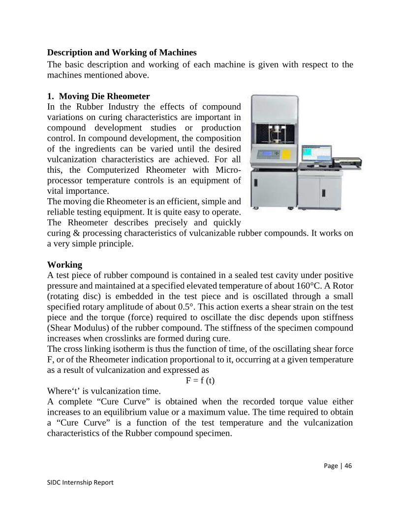
1. Moving Die RheometerIn the Rubber Industry the effects of compoundvariations on curing characteristics are important incompound development studies or productioncontrol. In compound development, the compositionof the ingredients can be varied until the desiredvulcanization characteristics are achieved. For allthis, the Computerized Rheometer with Micro-processor temperature controls is an equipment ofvital importance.The moving die Rheometer is an efficient, simple andreliable testing equipment. It is quite easy to operate.The Rheometer describes precisely and quicklycuring & processing characteristics of vulcanizable rubber compounds. It works ona very simple principle.
WorkingA test piece of rubber compound is contained in a sealed test cavity under positivepressure and maintained at a specified elevated temperature of about 160°C. A Rotor(rotating disc) is embedded in the test piece and is oscillated through a smallspecified rotary amplitude of about 0.5°. This action exerts a shear strain on the testpiece and the torque (force) required to oscillate the disc depends upon stiffness(Shear Modulus) of the rubber compound. The stiffness of the specimen compoundincreases when crosslinks are formed during cure.The cross linking isotherm is thus the function of time, of the oscillating shear forceF, or of the Rheometer indication proportional to it, occurring at a given temperatureas a result of vulcanization and expressed as
F = f (t)Where‘t’ is vulcanization time.A complete “Cure Curve” is obtained when the recorded torque value eitherincreases to an equilibrium value or a maximum value. The time required to obtaina “Cure Curve” is a function of the test temperature and the vulcanizationcharacteristics of the Rubber compound specimen.
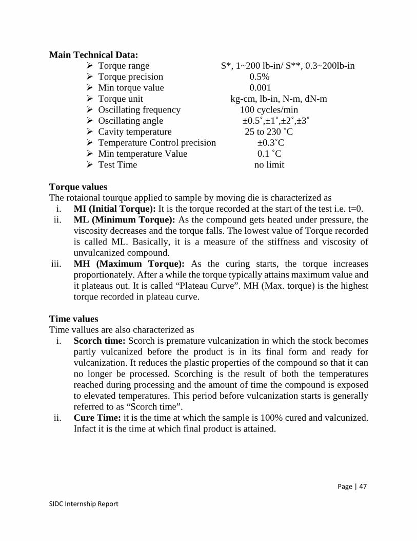
Page | 47
SIDC Internship Report
Main Technical Data: Torque range S*, 1~200 lb-in/ S**, 0.3~200lb-in Torque precision 0.5% Min torque value 0.001 Torque unit kg-cm, lb-in, N-m, dN-m Oscillating frequency 100 cycles/min Oscillating angle ±0.5˚,±1˚,±2˚,±3˚ Cavity temperature 25 to 230 ˚C Temperature Control precision ±0.3˚C Min temperature Value 0.1 ˚C Test Time no limit
Torque valuesThe rotaional tourque applied to sample by moving die is characterized as
i. MI (Initial Torque): It is the torque recorded at the start of the test i.e. t=0.ii. ML (Minimum Torque): As the compound gets heated under pressure, the
viscosity decreases and the torque falls. The lowest value of Torque recordedis called ML. Basically, it is a measure of the stiffness and viscosity ofunvulcanized compound.
iii. MH (Maximum Torque): As the curing starts, the torque increasesproportionately. After a while the torque typically attains maximum value andit plateaus out. It is called “Plateau Curve”. MH (Max. torque) is the highesttorque recorded in plateau curve.
Time valuesTime vallues are also characterized as
i. Scorch time: Scorch is premature vulcanization in which the stock becomespartly vulcanized before the product is in its final form and ready forvulcanization. It reduces the plastic properties of the compound so that it canno longer be processed. Scorching is the result of both the temperaturesreached during processing and the amount of time the compound is exposedto elevated temperatures. This period before vulcanization starts is generallyreferred to as “Scorch time”.
ii. Cure Time: it is the time at which the sample is 100% cured and valcunized.Infact it is the time at which final product is attained.

Page | 48
SIDC Internship Report
The graphical data of rheometer gives value of scorch and cure time asa) ts2 (Induction time). After attaining minimum torque, during cure phase, as
the torque rises, ts2 is scorch time for viscosity to rise 2 units above ML.b) ts5 (Scorch time). It is the time for viscosity (torque) to rise 5 units above
ML. Both ts2 are ts5 are measures of processing safetyc) tc50 (Optimum cure time). It is the time at which 50% of cure has taken
place.d) tc90 (Optimum Cure time). It is the time at which 90% of cure has taken
place.
The graphical representation of results from rheograph is as below:
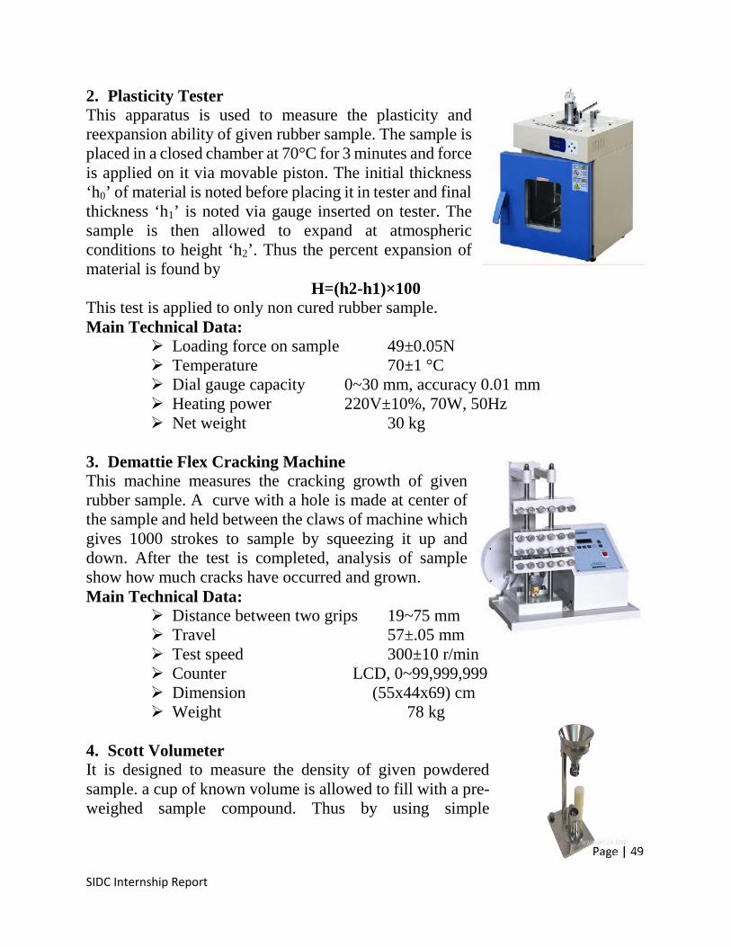
Page | 49
SIDC Internship Report
2. Plasticity TesterThis apparatus is used to measure the plasticity andreexpansion ability of given rubber sample. The sample isplaced in a closed chamber at 70°C for 3 minutes and forceis applied on it via movable piston. The initial thickness‘h0’ of material is noted before placing it in tester and finalthickness ‘h1’ is noted via gauge inserted on tester. Thesample is then allowed to expand at atmosphericconditions to height ‘h2’. Thus the percent expansion ofmaterial is found by
H=(h2-h1)×100This test is applied to only non cured rubber sample.Main Technical Data:
Loading force on sample 49±0.05N Temperature 70±1 °C Dial gauge capacity 0~30 mm, accuracy 0.01 mm Heating power 220V±10%, 70W, 50Hz Net weight 30 kg
3. Demattie Flex Cracking MachineThis machine measures the cracking growth of givenrubber sample. A curve with a hole is made at center ofthe sample and held between the claws of machine whichgives 1000 strokes to sample by squeezing it up anddown. After the test is completed, analysis of sampleshow how much cracks have occurred and grown.Main Technical Data:
Distance between two grips 19~75 mm Travel 57±.05 mm Test speed 300±10 r/min Counter LCD, 0~99,999,999 Dimension (55x44x69) cm Weight 78 kg
4. Scott VolumeterIt is designed to measure the density of given powderedsample. a cup of known volume is allowed to fill with a pre-weighed sample compound. Thus by using simple
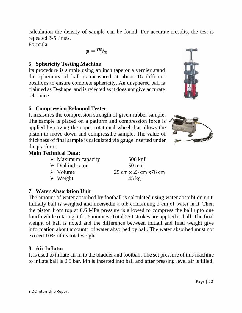
Page | 50
SIDC Internship Report
calculation the density of sample can be found. For accurate rresults, the test isrepeated 3-5 times.Formula = ⁄5. Sphericity Testing MachineIts procedure is simple using an inch tape or a vernier standthe sphericity of ball is measured at about 16 differentpositions to ensure complete sphericity. An unsphered ball isclaimed as D-shape and is rejected as it does not give accuraterebounce.
6. Compression Rebound TesterIt measures the compression strength of given rubber sample.The sample is placed on a patform and compression force isapplied bymoving the upper rotational wheel that allows thepiston to move down and compressthe sample. The value ofthickness of final sample is calculated via gauge inserted underthe platform.Main Technical Data:
Maximum capacity 500 kgf Dial indicator 50 mm Volume 25 cm x 23 cm x76 cm Weight 45 kg
7. Water Absorbtion UnitThe amount of water absorbed by football is calculated using water absorbtion unit.Initially ball is weighed and imersedin a tub comtaining 2 cm of water in it. Thenthe piston from top at 0.6 MPa pressure is allowed to compress the ball upto onefourth while rotating it for 6 minutes. Total 250 strokes are applied to ball. The finalweight of ball is noted and the difference between initiall and final weight giveinformation about amountt of water absorbed by ball. The water absorbed must notexceed 10% of its total weight.
8. Air InflatorIt is used to inflate air in to the bladder and football. The set pressure of this machineto inflate ball is 0.5 bar. Pin is inserted into ball and after pressing level air is filled.
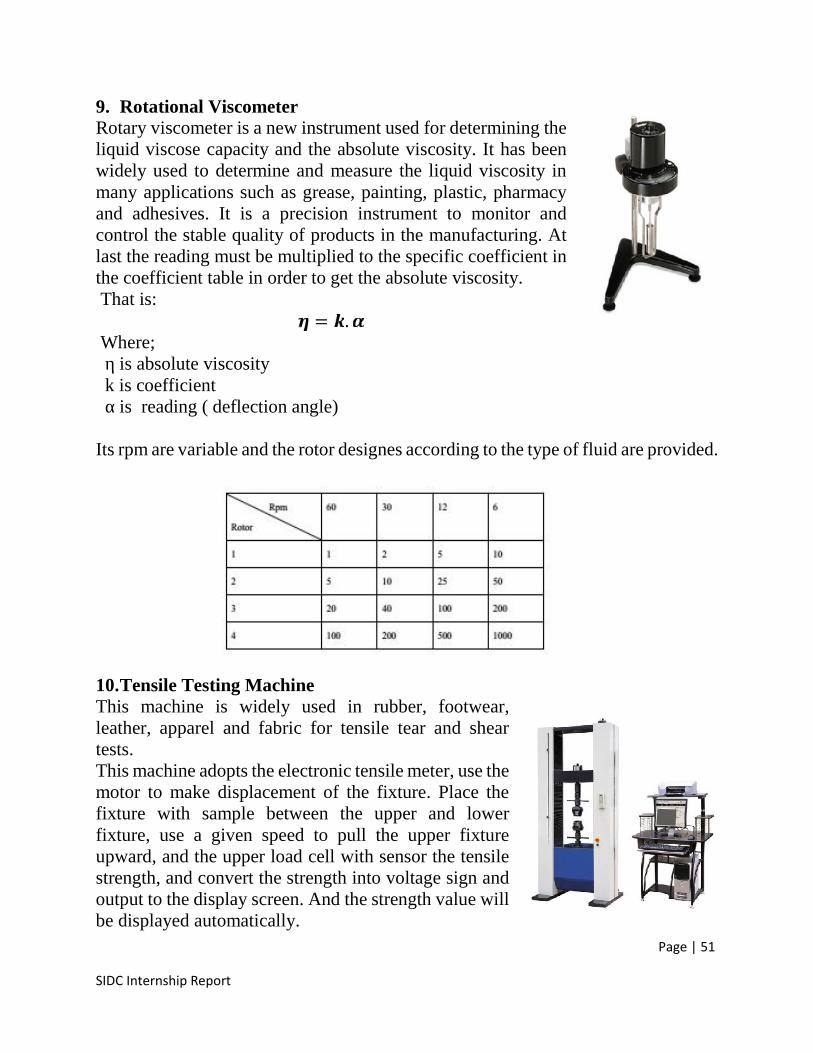
Page | 51
SIDC Internship Report
9. Rotational ViscometerRotary viscometer is a new instrument used for determining theliquid viscose capacity and the absolute viscosity. It has beenwidely used to determine and measure the liquid viscosity inmany applications such as grease, painting, plastic, pharmacyand adhesives. It is a precision instrument to monitor andcontrol the stable quality of products in the manufacturing. Atlast the reading must be multiplied to the specific coefficient inthe coefficient table in order to get the absolute viscosity.That is: = .Where;η is absolute viscosityk is coefficientα is reading ( deflection angle)
Its rpm are variable and the rotor designes according to the type of fluid are provided.
10.Tensile Testing MachineThis machine is widely used in rubber, footwear,leather, apparel and fabric for tensile tear and sheartests.This machine adopts the electronic tensile meter, use themotor to make displacement of the fixture. Place thefixture with sample between the upper and lowerfixture, use a given speed to pull the upper fixtureupward, and the upper load cell with sensor the tensilestrength, and convert the strength into voltage sign andoutput to the display screen. And the strength value willbe displayed automatically.
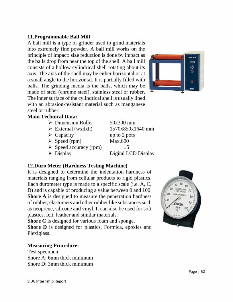
Page | 52
SIDC Internship Report
11.Programmable Ball MillA ball mill is a type of grinder used to grind materialsinto extremely fine powder. A ball mill works on theprinciple of impact: size reduction is done by impact asthe balls drop from near the top of the shell. A ball millconsists of a hollow cylindrical shell rotating about itsaxis. The axis of the shell may be either horizontal or ata small angle to the horizontal. It is partially filled withballs. The grinding media is the balls, which may bemade of steel (chrome steel), stainless steel or rubber.The inner surface of the cylindrical shell is usually linedwith an abrasion-resistant material such as manganesesteel or rubber.Main Technical Data:
Dimension Roller 50x300 mm External (wxdxh) 1570x850x1640 mm Capacity up to 2 pots Speed (rpm) Max.600 Speed accuracy (rpm) ±5 Display Digital LCD Display
12.Duro Meter (Hardness Testing Machine)It is designed to determine the indentation hardness ofmaterials ranging from cellular products to rigid plastics.Each durometer type is made to a specific scale (i.e. A, C,D) and is capable of producing a value between 0 and 100.Shore A is designed to measure the penetration hardnessof rubber, elastomers and other rubber like substances suchas neoprene, silicone and vinyl. It can also be used for softplastics, felt, leather and similar materials.Shore C is designed for various foam and sponge.Shore D is designed for plastics, Formica, epoxies andPlexiglass.
Measuring Procedure:Test specimenShore A: 6mm thick minimumShore D: 3mm thick minimum
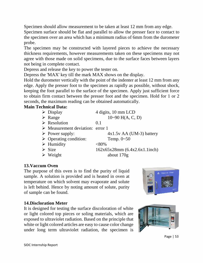
Page | 53
SIDC Internship Report
Specimen should allow measurement to be taken at least 12 mm from any edge.Specimen surface should be flat and parallel to allow the presser face to contact tothe specimen over an area which has a minimum radius of 6mm from the durometerprobe.The specimen may be constructed with layered pieces to achieve the necessarythickness requirements, however measurements taken on these specimens may notagree with those made on solid specimens, due to the surface faces between layersnot being in complete contact.Depress and release the key to power the tester on.Depress the 'MAX' key till the mark MAX shows on the display.Hold the durometer vertically with the point of the indenter at least 12 mm from anyedge. Apply the presser foot to the specimen as rapidly as possible, without shock,keeping the foot parallel to the surface of the specimen. Apply just sufficient forceto obtain firm contact between the presser foot and the specimen. Hold for 1 or 2seconds, the maximum reading can be obtained automatically.Main Technical Data:
Display 4 digits, 10 mm LCD Range 10~90 H(A, C, D) Resolution 0.1 Measurement deviation: error 1 Power supply: 4x1.5v AA (UM-3) battery Operating condition: Temp. 0~50 Humidity <80% Size 162x65x28mm (6.4x2.6x1.1inch) Weight about 170g
13.Vaccum OvenThe purpose of this oven is to find the purity of liquidsample. A solution is provided and is heated in oven attemperature on which solvent may evaporate and soluteis left behind. Hence by noting amount of solute, purityof sample can be found.
14.Discloration MeterIt is designed for testing the surface discoloration of whiteor light colored top pieces or soling materials, which areexposed to ultraviolet radiation. Based on the principle thatwhite or light colored articles are easy to cause color changeunder long term ultraviolet radiation, the specimen is
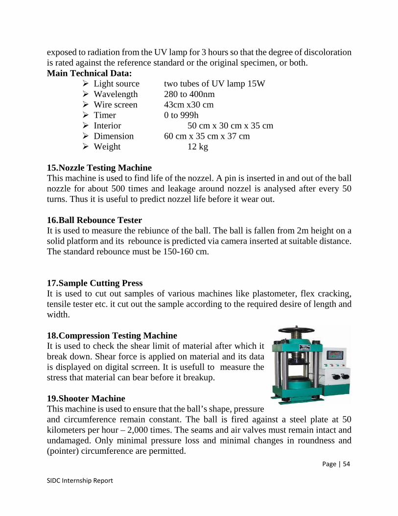
Page | 54
SIDC Internship Report
exposed to radiation from the UV lamp for 3 hours so that the degree of discolorationis rated against the reference standard or the original specimen, or both.Main Technical Data:
Light source two tubes of UV lamp 15W Wavelength 280 to 400nm Wire screen 43cm x30 cm Timer 0 to 999h Interior 50 cm x 30 cm x 35 cm Dimension 60 cm x 35 cm x 37 cm Weight 12 kg
15.Nozzle Testing MachineThis machine is used to find life of the nozzel. A pin is inserted in and out of the ballnozzle for about 500 times and leakage around nozzel is analysed after every 50turns. Thus it is useful to predict nozzel life before it wear out.
16.Ball Rebounce TesterIt is used to measure the rebiunce of the ball. The ball is fallen from 2m height on asolid platform and its rebounce is predicted via camera inserted at suitable distance.The standard rebounce must be 150-160 cm.
17.Sample Cutting PressIt is used to cut out samples of various machines like plastometer, flex cracking,tensile tester etc. it cut out the sample according to the required desire of length andwidth.
18.Compression Testing MachineIt is used to check the shear limit of material after which itbreak down. Shear force is applied on material and its datais displayed on digital scrreen. It is usefull to measure thestress that material can bear before it breakup.
19.Shooter MachineThis machine is used to ensure that the ball’s shape, pressureand circumference remain constant. The ball is fired against a steel plate at 50kilometers per hour – 2,000 times. The seams and air valves must remain intact andundamaged. Only minimal pressure loss and minimal changes in roundness and(pointer) circumference are permitted.
Page | 55
SIDC Internship Report
Recommendations
The bladder sections muust be properly vantilated to avoid andy suffocationof worker working there.
Some machines in bladder hall are temperature sensitive, so properconditioning must be provided to make quality standards product.
Each curing machines must have its own exaust fan so that the machine maynot heat up beyond limits and worker operating it may not suffocate.
The complete bladder section must be made duust proof because tiny dustparticles can alter the quality of product .
Labouratory section must have air sealed enviornment to carry out sensitivereeadings greatfully.
Boiler section and compressor section must be made far away from workingarea to limit the hazards of danger.
A complete boiler understander must be hired so that he may tackle thealarming situation effectively.
The workers must be trained properly with regular intervals with the latesttechniques of bladder and football making. For this purpose an engineer orfootball related person must be hired whose sole purpose must be to be awareof lateest technology and teach them to the workers.
Page | 56
SIDC Internship Report
References
1. https://www.wbdg.org/ccb/NAVFAC/OPER/mo206.pdf
2. https://www.americantrainco.com/pdfs/studyguide-bo.pdf
3. http://www.moeschle.de/files/upload/S350_engl.pdf
4. http://www.iisrp.com/WebPolymers/00Rubber_Intro.pdf
5. http://wwwme.nchu.edu.tw/~CIM/courses/Manufacturing%20Processes/Ch14-Rubber-Wiley.pdf
6. http://www.uotechnology.edu.iq/depmaterials/lecture/thirdclass/RubberTechnology3.pdf
7. http://www.brcil.com/common/downloads/technical/Rolling_Mill_Rolls.pdf
8. http://www.chemfilt.com/PDF%20Files/SIGMA%20KNEADER.pdf
9. http://ir.library.oregonstate.edu/xmlui/bitstream/handle/1957/5199/Basic_Water_ocr.pdf
10.http://www.gibitre.it/Eng/Pdf/MoreRheoMd.pdf
11.http://researchcommons.waikato.ac.nz/bitstream/handle/10289/8094/A%20new%20method.pdf?sequence=1
12.http://4tsi.com/wp-content/uploads/2012/10/What-is-Durometer.pdf
13.http://www.akrochem.com/pdf/product/rubber_chemicals/accelerator_mbt.pdf
14.http://www.akrochem.com/pdf/product/rubber_chemicals/accelerator_mbts.pdf