shuffling of keypad for securing electronic gadgets
DESCRIPTION
it is a project done on securing electronic gadgets using shuffling of keypads rather than using mechanical keysTRANSCRIPT
Virtual Shuffling of Keypad for Electronic Gadgets
1. INTRODUCTION
The purpose of this project is to implement the novel idea which can be used to
design the keypad access system whose key arrangements will get change every time when
we use the keypad. Nowadays, in ATM there are more chances of password being recognized
by the people standing behind us or sometimes they intentionally note our password and try
to guess it. In ATM whenever we want to withdraw the money we have to enter the pin code
and get access to our account. But people behind us intentionally observe our finger
movements and try to guess the password, only thing they have to do is pick pocketing and
snatch the ATM card. Already they have guessed the finger movements and they will try
with this pin code and get the money.
Here we need a novel security access system which provides better security for the
ATM access systems. Our idea is to implement the shuffling keypad whose keypad
arrangements will get change every time when we use it. Every time we use the keypad next
time we get the different layout.
In today’s world all keypad based access authentication system there are chances of
password being overseen by any third persons who are standing near us. Low lying persons
can purposely note our finger movements on the keypad and try to guess the password.
Especially in ATM counter whenever we want to withdraw money we have to enter pin and
then get access to our account. But if someone sees how we are entering the password they
can make out our pin then only thing is they have to get our ATM card for that they can do
pick pocketing or they can assault us and snatch the ATM card now as already they have
finger movements of ours in the mind they can enter our pin and withdraw the money. This
problem was also described in Bangalore mirror news paper of 5th September 2011. Even by
using various chemical agents, such as phenolphthalein and fluorescent light theft is easily
possible.
Dept. of E&C, S.S.I.T, TUMKUR 2011-2012 Page No.1
Virtual Shuffling of Keypad for Electronic Gadgets
Not only in ATM, we are using keypads at many places and our own finger
movements are putting our security at risk, for this problem we have come up with an
innovative solution of shuffling keypad which will confuse the culprits and they would not be
able to detect the password from our finger movements on the keypad. Our idea is to
implement a shuffling keypad whose key arrangement will change after every use, even if in
last use the password was not accepted. Every time we use the keypad next time we will get
different layout.
Figure 1.1: Shuffling keypad layout
Dept. of E&C, S.S.I.T, TUMKUR 2011-2012 Page No.2

Virtual Shuffling of Keypad for Electronic Gadgets
1.1 Objective:
Security playing an important role in present world and everybody want to be safe in
life. Here the main objective of our project is to design a novel keypad access system whose
keypad arrangement will change after every use. Every time when we make the use of the
keypad next time the keypad arrangement will get shuffle and we will get different layout of
keypad.
1.2 Motivation:
In present world we are using keypads at many places and our own finger movements
are putting our security at risk, for this problem we have come up with an innovative solution
of shuffling keypad which will confuse the culprits and they would not be able to detect the
password from our finger movements on the keypad.
Our idea is to implement a shuffling keypad whose key arrangement will change after
every use, even if in last use the password was not accepted. Every time we use the keypad
next time we will get different layout.
1.3 Problem Statement:
In ATM there are more chances of password being recognized by the people standing
behind us or sometimes they intentionally note our password and try to guess it. This leads to
theft of money. What method can be used to prevent from it?
1.4 Solution to the Problem:
By using virtual shuffling keypad we can secure the password used in ATM or any
other electronic gadgets. After every transaction the keypad gets shuffled and this leads to
more secure authentication.
Dept. of E&C, S.S.I.T, TUMKUR 2011-2012 Page No.3
Virtual Shuffling of Keypad for Electronic Gadgets
1.5 Methodology:
The waterfall model is a sequential design process, often used in software
development process, in which progress is seen as flowing steadily downwards. The design
and development of our project work is done with the help of following procedures:
1. Requirements
2. Design
3. Construction
4. Coding & Testing
5. Implementation
Figure1.2: Waterfall model
The virtual shuffling of keypad is mainly designed either on resistive touch screen or
mechanical key pad. A graphical LCD is provided to the user which uses in order to enter the
password for their required purposes. After the user enters the password, the keypad
available to it changes automatically and a new modified keypad is now available to the
second user. The user enters the password with the help of keypad on the touch screen; the
main system recognizes it and then changes the whole matrix of the keypad with the help of
micro-controllers which will be now active for the next user.
The purpose of using waterfall development is that it allows for departmentalization
and managerial control. Development moves from concept through design, implementation,
testing, installation, troubleshooting, and ends up at operation and maintenance.
Dept. of E&C, S.S.I.T, TUMKUR 2011-2012 Page No.4
Virtual Shuffling of Keypad for Electronic Gadgets
2. LITERATURE SURVEY
A touch screen is an electronic visual display that can detect the presence and location
of a touch within the display area. Thus this technology is widely used all over the world in
many areas such as ATM’s, Bank lockers etc for security purposes. But this touch screen
technology used for security also has some loop holes. So in order to overcome this
drawback, we will use the shuffling of the keypad after every use by the user. Here are some
of the technologies which are helpful for the security.
Resistive Touch Screen Technology
Here we describe a new interface system for a fast resistive X-Y 4-wire touch screen.
The system enables the determination of both X-Y position and the touch-point resistance.
The interface uses advanced measurement techniques, including three-signal auto-calibration,
synchronous detection and two-port measurement. The interface electronics has been
designed to interface between the touch-screen sensor and a PC, using the Universal Serial
Bus (USB) protocol. The X-Y position interface uses a very linear relaxation oscillator,
which converts X-Y position and touch-point resistance signals to a period-modulated signal.
A microcontroller is used to read out the modulated signal, to control the switches
and to send the information to the USB interface device. The USB interface device is used to
communicate between the microcontrollers with any device with USB protocol, such as a
PC. A phase-locked-loop is included in the USB interface to multiply from 6 MHz to 48
MHz, for the USB communication.[1]
Capacitive Touch Screen Technology
This is a highly area-efficient controller for capacitive touch screen panels (TSPs)
being proposed. The proposed controller uses a 10-bit successive approximation register
analog-to-digital converter (SAR ADC) with an adder to compensate for the capacitance
variation in the TSP and for the offset voltage variation in the charge amplifier of the sensing
circuit. By using the proposed compensation method, the area of the controller can be
Dept. of E&C, S.S.I.T, TUMKUR 2011-2012 Page No.5
Virtual Shuffling of Keypad for Electronic Gadgets
reduced by 90.3% of the area of the conventional controllers. The measurement results
showed that the signal-to-noise ratio (SNR) of the controller increases from 12.5 to 21.3 dB
after compensation. Also, its spatial jitter decreases from ±1.5 to ±0.46 mm, which is 7% of
the sensor pitch of 8 mm.[2]
USARTs (Universal Synchronous Asynchronous Receiver Transmitter)
These are serial chips on our PC motherboard (or on an internal modem card). The
USART function may also be done on a chip that does other things as well. On older
computers like many 486's, the chips were on the disk IO controller card. Still older
computers have dedicated serial boards. The USARTs purpose is to convert bytes from the
PC's parallel bus to a serial bit-stream. The cable going out of the serial port is serial and has
only one wire for each direction of flow. The serial port sends out a stream of bits, one bit at
a time. Conversely, the bit stream that enters the serial port via the external cable is converted
to parallel bytes that the computer can understand. USARTs deal with data in byte-sized
pieces, which is conveniently also the size of ASCII character.[3]
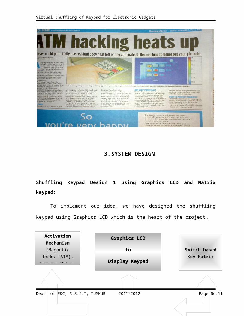
“BANGALORE MIRROR” paper showing ATM hacking
Dept. of E&C, S.S.I.T, TUMKUR 2011-2012 Page No.6

Virtual Shuffling of Keypad for Electronic Gadgets
3. SYSTEM DESIGN
Shuffling Keypad Design 1 using Graphics LCD and Matrix keypad:
To implement our idea, we have designed the shuffling keypad using Graphics LCD
which is the heart of the project.
Figure 3.1: Implementation of Shuffling keypad using switch Matrix and Graphics LCD
DESCRIPTION
Graphic LCD is 128X64 pixel, each pixel is programmable so we can make image of layout
of keys as discussed earlier in introduction.
MICROCONTROLLER: We are using P89V51RD2 as our core microcontroller which
controls all the other components including keypad and graphics LCD this microcontroller is
based on 8051 but with extended memory and peripherals
Mechanism: To demonstrate the security feature we have implemented relay control system to give demo of lock/door open and close to show whether the password is correct or not.
Dept. of E&C, S.S.I.T, TUMKUR 2011-2012 Page No.7
Activation Mechanism
(Magnetic locks (ATM), Stepper
Motor, Solenoid)
Graphics LCD
to
Display Keypad
Switch based Key Matrix
NXP P89V51RD2 MCU

Virtual Shuffling of Keypad for Electronic Gadgets
Matrix Keypad: This is 4X4 matrix switch based keypad with 16 keys, we have
implemented row column scan routine to detect which key is pressed
As in above implementation it’s seen that switches are kept separately and virtual
keypad is realized on Graphics LCD. Sometimes this can be little inconvenient, as key
correlation has to be done and corresponding switch has to be pressed after seeing the
display.
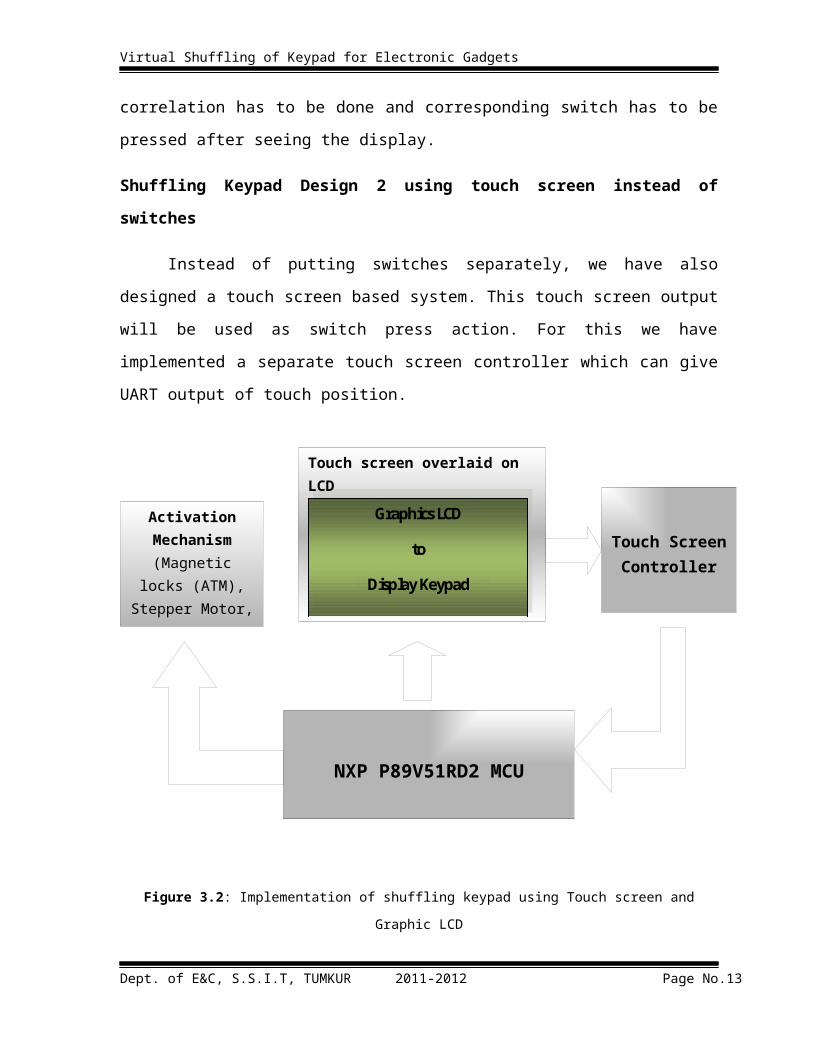
Shuffling Keypad Design 2 using touch screen instead of switches
Instead of putting switches separately, we have also designed a touch screen based
system. This touch screen output will be used as switch press action. For this we have
implemented a separate touch screen controller which can give UART output of touch
position.
Figure 3.2: Implementation of shuffling keypad using Touch screen and Graphic LCD
Dept. of E&C, S.S.I.T, TUMKUR 2011-2012 Page No.8
NXP P89V51RD2 MCU
Activation Mechanism
(Magnetic locks (ATM), Stepper
Motor, Solenoid)
Graphics LCD
to
Display Keypad
Touch screen overlaid on LCD Graphics LCD
to
Display Keypad
Touch Screen Controller

General Purpose MCU
Resistive Touch ScreenSwitch/
Multiplexer
ADC
Virtual Shuffling of Keypad for Electronic Gadgets
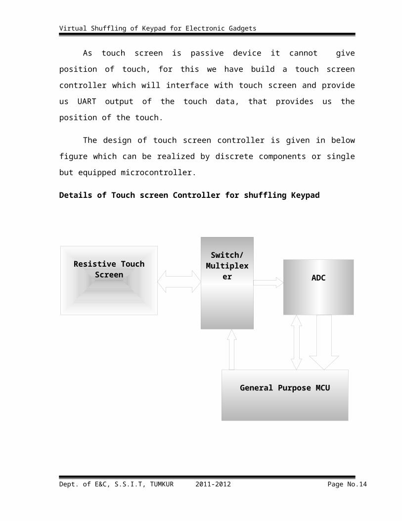
As touch screen is passive device it cannot give position of touch, for this we have
build a touch screen controller which will interface with touch screen and provide us UART
output of the touch data, that provides us the position of the touch.
The design of touch screen controller is given in below figure which can be realized
by discrete components or single but equipped microcontroller.
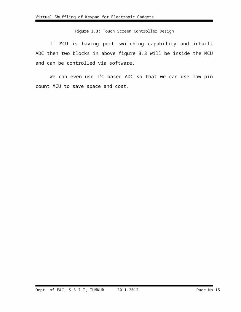
Details of Touch screen Controller for shuffling Keypad
Figure 3.3: Touch Screen Controller Design
If MCU is having port switching capability and inbuilt ADC then two blocks in above
figure 3.3 will be inside the MCU and can be controlled via software.
We can even use I2C based ADC so that we can use low pin count MCU to save
space and cost.
Dept. of E&C, S.S.I.T, TUMKUR 2011-2012 Page No.9

Virtual Shuffling of Keypad for Electronic Gadgets
4. HARDWARE REQUIREMENT
4.1 MICROCONTROLLER (P89V51RD2)
Computer in its simplest form needs at least 3 basic blocks: CPU, I/O and the
RAM/ROM. The integrated form of CPU is the microprocessor. As the use of
microprocessors in control applications increased, development of microcontroller unit or
MCU took shape, wherein CPU, I/O and some limited memory on a single chip was
fabricated. Intention was to reduce the chip count as much as possible. We decided to use
P89V51RD2 microcontroller.
The P89V51RD2 are 80C51 microcontrollers with 64 KB flash and 1024 B of data
RAM. A key feature of the P89V51RD2 is its X2 mode option. The design engineer can
choose to run the application with the conventional 80C51 clock rate (12 clocks per machine
cycle) or select the X2 mode (six clocks per machine cycle) to achieve twice the throughput
at the same clock frequency. Another way to benefit from this feature is to keep the same
performance by reducing the clock frequency by half, thus dramatically reducing the EMI.
The flash program memory supports both parallel programming and in serial ISP.
Parallel programming mode offers gang-programming at high speed, reducing programming
costs and time to market. ISP allows a device to be reprogrammed in the end product under
software control. The capability to field/update the application firmware makes a wide range
of applications possible. The P89V51RD2 is also capable of IAP, allowing the flash program
memory to be reconfigured even while the application is running.
Figure 4.1: Microcontroller P89V51RD2
Dept. of E&C, S.S.I.T, TUMKUR 2011-2012 Page No.10
Virtual Shuffling of Keypad for Electronic Gadgets
4.1.1 Features:
1. 80C51 Central Processing Unit
2. 5 V Operating voltage from 0 to 40 MHz
3. 64 KB of on-chip Flash program memory with ISP (In-System Programming) and
IAPb (In-Application Programming)
4. SPI (Serial Peripheral Interface) and enhanced UART
5. Supports 12-clock (default) or 6-clock mode selection via software or ISP
6. Four 8-bit I/O ports with three high-current Port 1 pins
7. Three 16-bit timers/counters
8. Programmable Watchdog timer (WDT)
9. Eight interrupt sources with four priority levels
10. TTL- and CMOS-compatible logic levels
11. Brown-out detection
12. Low power mode
13. PDIP40, PLCC44 and TQFP44 packages
14. Low EMI mode (ALE inhibit)
15. Second DPTR register
Dept. of E&C, S.S.I.T, TUMKUR 2011-2012 Page No.11

Virtual Shuffling of Keypad for Electronic Gadgets
4.1.2 Block Diagram:
Figure 4.2: Block Diagram of P89V51RD2 Microcontroller
Dept. of E&C, S.S.I.T, TUMKUR 2011-2012 Page No.12
Virtual Shuffling of Keypad for Electronic Gadgets
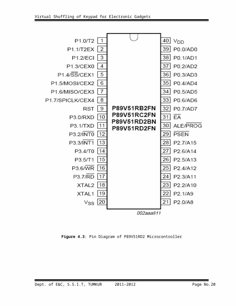
4.1.3 Pin Diagram:
Figure 4.3: Pin Diagram of P89V51RD2 Microcontroller
Dept. of E&C, S.S.I.T, TUMKUR 2011-2012 Page No.13
Virtual Shuffling of Keypad for Electronic Gadgets
4.1.4 Pin description of P89CV51RXX:
Port-0: Port-0 is an 8-bit open drain bidirectional I/O port. Port-0 pins that have ‘1’s written
to them float, and in this state can be used as high-impedance inputs. Port-0 is also the
multiplexed low-order address and data bus during accesses to external code and data
memory. In this application, it uses strong internal pull-ups when transitioning to ‘1’s. Port-0
also receives the code bytes during the external host mode programming, and outputs the
code bytes during the external host mode verification. External pull-ups are required during
program verification or as a general purpose I/O port.
Port-1: Port-1 is an 8-bit bidirectional I/O port with internal pull-ups. The Port-1 pins are
pulled high by the internal pull-ups when ‘1’s are written to them and can be used as inputs
in this state. As inputs, Port-1 pins that are externally pulled LOW will source current (IIL)
because of the internal pull-ups. P1.5, P1.6, P1.7 have high current drive of 16 mA. Port-1
also receives the low-order address bytes during the external host mode programming and
verification.
Port-2: Port-2 is an 8-bit bidirectional I/O port with internal pull-ups. Port-2 pins are pulled
HIGH by the internal pull-ups when ‘1’s are written to them and can be used as inputs in this
state. As inputs, Port-2 pins that are externally pulled LOW will source current (IIL) because
of the internal pull-ups. Port-2 sends the high-order address byte during fetches from external
program memory and during accesses to external Data Memory that use 16-bit address
(MOVX@DPTR). In this application, it uses strong internal pull-ups when transitioning to
‘1’s. Port-2 also receives some control signals and a partial of high-order address bits during
the external host mode programming and verification.
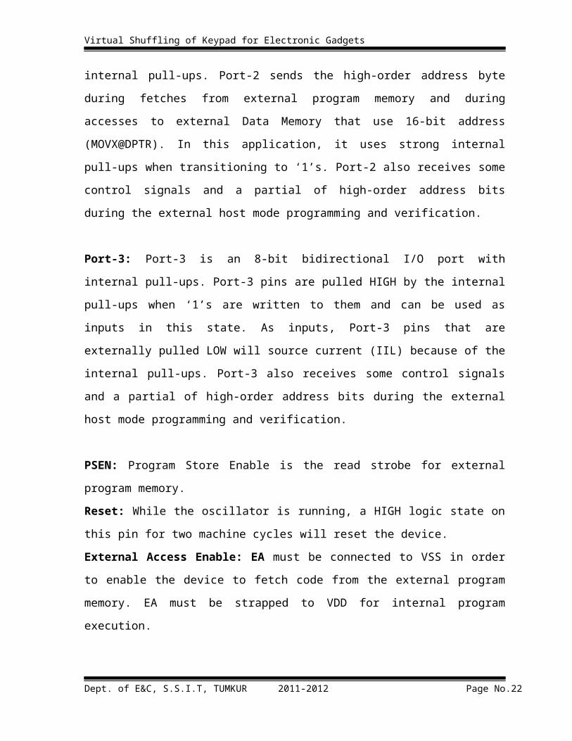
Port-3: Port-3 is an 8-bit bidirectional I/O port with internal pull-ups. Port-3 pins are pulled
HIGH by the internal pull-ups when ‘1’s are written to them and can be used as inputs in this
state. As inputs, Port-3 pins that are externally pulled LOW will source current (IIL) because
of the internal pull-ups. Port-3 also receives some control signals and a partial of high-order
address bits during the external host mode programming and verification.
Dept. of E&C, S.S.I.T, TUMKUR 2011-2012 Page No.14
Virtual Shuffling of Keypad for Electronic Gadgets
PSEN: Program Store Enable is the read strobe for external program memory.
Reset: While the oscillator is running, a HIGH logic state on this pin for two machine cycles
will reset the device.
External Access Enable: EA must be connected to VSS in order to enable the device to
fetch code from the external program memory. EA must be strapped to VDD for internal
program execution.
Address Latch Enable: ALE is the output signal for latching the low byte of the address
during an access to external memory. This pin is also the programming pulse input (PROG)
for flash programming.
Crystal 1: Input to the inverting oscillator amplifier and input to the internal clock generator
circuits.
Crystal 2: Output from the inverting oscillator amplifier.
VCC: Supply voltage.
GND: Ground.
Dept. of E&C, S.S.I.T, TUMKUR 2011-2012 Page No.15
Virtual Shuffling of Keypad for Electronic Gadgets
The additional feature of Port3
Table 4.1: Additional feature of Port3
4.2 Graphic LCD
4.2.1 Introduction
JHD12864J is a light weight, low power consumption liquid crystal graphic display.
The module measures 54.0x50.0mm only. Supply voltage is 5V matching the voltage for
most microcontrollers. The LCD controller is Samsung KS0108B.
Figure 4.4: Graphic LCD
Unlike most character-based LCDs which use 4-bit data bus, JHD12864J module uses
8-bit data bus (DB0 – DB7). Nevertheless, it is a straight forward module comparing to other
LCD series like T6963C1. JHD12864J is split logically in half with controller #1 (CS1)
driving the left half of the display, and controller #2 (CS2) driving the right half. Each
Dept. of E&C, S.S.I.T, TUMKUR 2011-2012 Page No.16

Virtual Shuffling of Keypad for Electronic Gadgets
controller must be addressed independently. The page addresses, 0-7, specify one of the 8
horizontal pages which are 8 bits (1 byte) high. A drawing of the display and how it is
mapped to the refresh memory is shown below.
Figure 4.5: Map of LCD pixel
Dept. of E&C, S.S.I.T, TUMKUR 2011-2012 Page No.17

Virtual Shuffling of Keypad for Electronic Gadgets
4.2.2 Block Diagram:
Figure 4.6: Block Diagram of Graphic LCD
Dept. of E&C, S.S.I.T, TUMKUR 2011-2012 Page No.18

Virtual Shuffling of Keypad for Electronic Gadgets
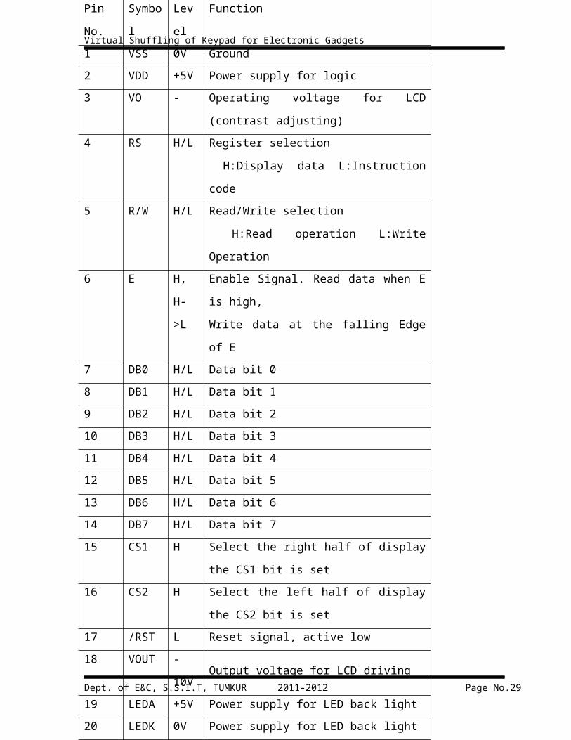
4.2.3 Pin Description:
This LCD has 20 lines interfacing which are described below:
Table 4.2: Pin description of Graphic LCD
Dept. of E&C, S.S.I.T, TUMKUR 2011-2012 Page No.19
Pin
No.
Symbol Level Function
1 VSS 0V Ground
2 VDD +5V Power supply for logic
3 VO - Operating voltage for LCD (contrast adjusting)
4 RS H/L Register selection
H:Display data L:Instruction code
5 R/W H/L Read/Write selection
H:Read operation L:Write Operation
6 E H,
H->L
Enable Signal. Read data when E is high,
Write data at the falling Edge of E
7 DB0 H/L Data bit 0
8 DB1 H/L Data bit 1
9 DB2 H/L Data bit 2
10 DB3 H/L Data bit 3
11 DB4 H/L Data bit 4
12 DB5 H/L Data bit 5
13 DB6 H/L Data bit 6
14 DB7 H/L Data bit 7
15 CS1 H Select the right half of display the CS1 bit is set
16 CS2 H Select the left half of display the CS2 bit is set
17 /RST L Reset signal, active low
18 VOUT -10V Output voltage for LCD driving
19 LEDA +5V Power supply for LED back light
20 LEDK 0V Power supply for LED back light
Virtual Shuffling of Keypad for Electronic Gadgets
4.2.4 Display Control Instruction:
The display control instructions control the internal state of KS0108B. The instruction is received from MPU to KS0108B for display control. The following table shows various instructions:
Table 4.3: Display Control Instructions of GLCD
Instructions RS RW DB7 DB6 DB5 DB4 DB3 DB2 DB1 DB0 FunctionRead Display data
1 1 Read dataRead data(DB7:0) from display data RAM
Write display data 1 0 Write data
Write data(DB7:0) into display data RAM
Status Read0 1 Busy 0 ON/
OFFRe- set
0 0 0 0
Read the internal status BUSY0: Ready1:In operationON/OFF0:Display on1:Display offRESET0: Normal1: Reset
Set Address0 0 0 1 Y Address(0-63)
Set Y address in Y address counter
Set display Start Line 0 0 1 1 Display Start line(0-63)
Indicate the display data RAM displayed at the top of the screen.
Set Address0 0 1 0 1 1 1 Page(0-7)
Set X address in X address counter
Display ON/OFF 0 0 0 0 1 1 1 1 1 1/0
Control the display ON/OFF.(1/0)
Dept. of E&C, S.S.I.T, TUMKUR 2011-2012 Page No.20

Virtual Shuffling of Keypad for Electronic Gadgets
Display ON/OFF:
The display data appears when D is 1 and disappears when D is 0. Though the data is
not on the screen with D=0, it remains in the display data RAM. Therefore, we can make it
appear by changing D=0 into D=1.
RS R/W DB7 DB6 DB5 DB4 DB3 DB2 DB1 DB00 0 0 0 1 1 1 1 1 D
Set Address(Y Address):
Y address (AC0~AC5) of the display data RAM is set in the Y address counter. An
address is set by instruction and increased by 1 automatically by read or write operation of
display data.
RS R/W DB7 DB6 DB5 DB4 DB3 DB2 DB1 DB00 0 0 1 AC5 AC4 AC3 AC2 AC1 AC0
Set Page(X Address):
X address (AC0~AC2) of the display data Ram is set in the X address register.
Writing or reading to or from MPU is executed in this specified page until the next page is
set.
RS R/W DB7 DB6 DB5 DB4 DB3 DB2 DB1 DB00 0 1 0 1 1 1 AC2 AC1 AC0
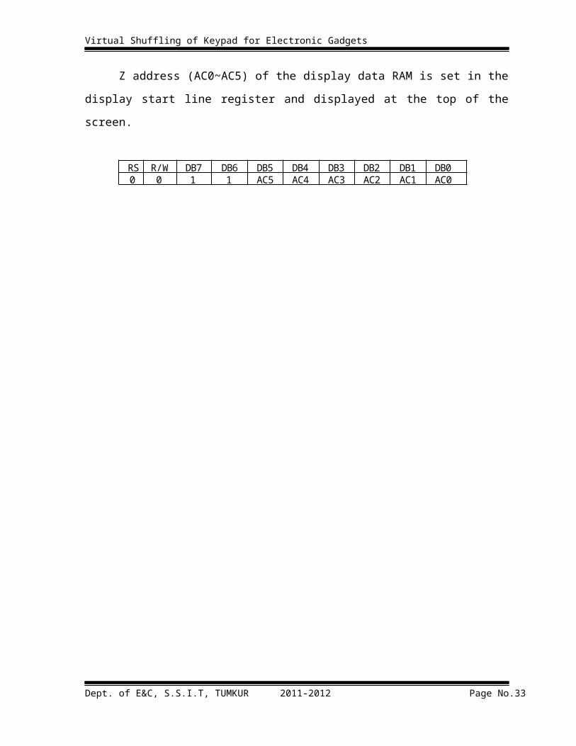
Display Start Line (Z Address):
Z address (AC0~AC5) of the display data RAM is set in the display start line register
and displayed at the top of the screen.
RS R/W DB7 DB6 DB5 DB4 DB3 DB2 DB1 DB00 0 1 1 AC5 AC4 AC3 AC2 AC1 AC0
Dept. of E&C, S.S.I.T, TUMKUR 2011-2012 Page No.21
Virtual Shuffling of Keypad for Electronic Gadgets
Status Read:
BUSY
When BUSY is 1, the chip is executing internal operation and no instruction are accepted.
When BUSY is 0, the chip ready to accept any instruction.
ON/OFF
When ON/OFF is 1, the display is off.
When ON/OFF is 0, the display is on.
RESET
When RESET is 1, the system is being initialized. In this condition no instruction except
status read can be accepted.
When RESET is 0, initializing has finished and the system is in normal operation condition.
RS R/W DB7 DB6 DB5 DB4 DB3 DB2 DB1 DB01 0 BUSY 0 ON/OFF RESET 0 0 0 0
Write Display Data:
Write data (D7~D0) into the display data RAM. After writing instruction, Y address
is increased by 1 automatically.
RS R/W DB7 DB6 DB5 DB4 DB3 DB2 DB1 DB01 0 D7 D6 D5 D4 D3 D2 D1 D0
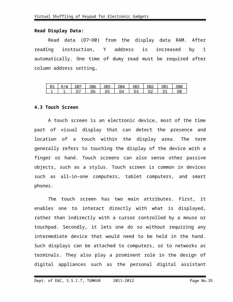
Read Display Data:
Read data (D7~D0) from the display data RAM. After reading instruction, Y address
is increased by 1 automatically. One time of dumy read must be required after column
address setting.
RS R/W DB7 DB6 DB5 DB4 DB3 DB2 DB1 DB01 1 D7 D6 D5 D4 D3 D2 D1 D0
Dept. of E&C, S.S.I.T, TUMKUR 2011-2012 Page No.22

Virtual Shuffling of Keypad for Electronic Gadgets
4.3 Touch Screen
A touch screen is an electronic device, most of the time part of visual display that can
detect the presence and location of a touch within the display area. The term generally refers
to touching the display of the device with a finger or hand. Touch screens can also sense
other passive objects, such as a stylus. Touch screen is common in devices such as all-in-one
computers, tablet computers, and smart phones.
The touch screen has two main attributes. First, it enables one to interact directly with
what is displayed, rather than indirectly with a cursor controlled by a mouse or touchpad.
Secondly, it lets one do so without requiring any intermediate device that would need to be
held in the hand. Such displays can be attached to computers, or to networks as terminals.
They also play a prominent role in the design of digital appliances such as the personal
digital assistant (PDA), satellite navigation devices, mobile phones, and video games.
4.3.1 Types of Touch Screen
1. Resistive Touch screen
2. Capacitive Touch Screen
3. Surface Acoustic Touch Screen
4. Infrared Touch Screen
4.3.2 Resistive Touch Screen
A resistive touch screen panel is composed of several layers, the most important of
which are two thin, electrically conductive layers separated by a narrow gap.
Figure 4.7: Resistive Touch Screen
Dept. of E&C, S.S.I.T, TUMKUR 2011-2012 Page No.23

Virtual Shuffling of Keypad for Electronic Gadgets
When an object, such as a finger, presses down on a point on the panel's outer surface
the two metallic layers become connected at that point. The panel then behaves as a pair of
voltage dividers with connected outputs. This causes a change in the electrical current, which
is registered as a touch event and sent to the controller for processing.
There are various resistive touch screens available like 4wire, 5wire, 6wire and
8wires touch screen in various sizes. Most popular one is 4wire and 5wire touch screen.
4.3.3 Four Wire Resistive Touch Screen
In our project we have used 4 wire Resistive touch screens. Resistive 4-wire and 5-
wire touch systems belong to the most popular and most common touch screen technologies.
Their market share is about 75%, mainly due to their low costs and simple interface
electronics. Resistive System can be found in various mobile applications including PDAs
and Smart phones.
Advantages in using Resistive touch screens:
Resistive touch screens are easily available as most of mobiles and other portable
devices use this kind of touch screen.
Interfacing to resistive touch screens is easier compared to other touch screens.
Resistive touch screen are cheaper compared to other input devices.
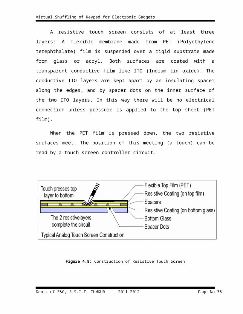
Construction of Resistive Touch screen:
A resistive touch screen consists of at least three layers: A flexible membrane made
from PET (Polyethylene terephthalate) film is suspended over a rigid substrate made from
glass or acryl. Both surfaces are coated with a transparent conductive film like ITO (Indium
tin oxide). The conductive ITO layers are kept apart by an insulating spacer along the edges,
and by spacer dots on the inner surface of the two ITO layers. In this way there will be no
electrical connection unless pressure is applied to the top sheet (PET film).
When the PET film is pressed down, the two resistive surfaces meet. The position of
this meeting (a touch) can be read by a touch screen controller circuit.
Dept. of E&C, S.S.I.T, TUMKUR 2011-2012 Page No.24

Virtual Shuffling of Keypad for Electronic Gadgets
Figure 4.8: Construction of Resistive Touch Screen
Before going to understand how to measure X and Y position first we have to understand
how connections are made is top and bottom layer and coating configuration.
Figure 4.9: Coating of both layer and connection of touch screen.
Dept. of E&C, S.S.I.T, TUMKUR 2011-2012 Page No.25

Virtual Shuffling of Keypad for Electronic Gadgets
4.3.4 Measuring X and Y Position:
Now we will understand how to measure X and Y position by providing correct connections
to different layers.
Figure 4.10: Measuring X position
Figure 4.11: Measuring Y position.
Dept. of E&C, S.S.I.T, TUMKUR 2011-2012 Page No.26

Virtual Shuffling of Keypad for Electronic Gadgets
After understanding above two procedures we have concluded following table for
connections for x any y position measurement.
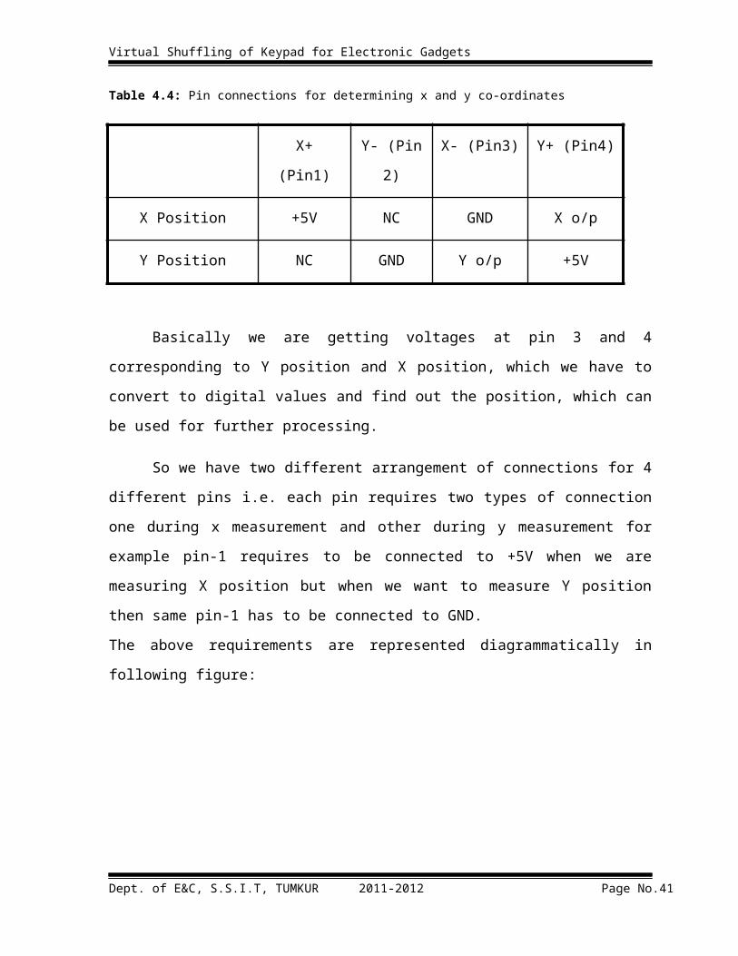
Table 4.4: Pin connections for determining x and y co-ordinates
X+ (Pin1) Y- (Pin 2) X- (Pin3) Y+ (Pin4)
X Position +5V NC GND X o/p
Y Position NC GND Y o/p +5V
Basically we are getting voltages at pin 3 and 4 corresponding to Y position and X
position, which we have to convert to digital values and find out the position, which can be
used for further processing.
So we have two different arrangement of connections for 4 different pins i.e. each pin
requires two types of connection one during x measurement and other during y measurement
for example pin-1 requires to be connected to +5V when we are measuring X position but
when we want to measure Y position then same pin-1 has to be connected to GND.
The above requirements are represented diagrammatically in following figure:
Figure 4.12: Switching Requirement for X and Y position measurement (Left side connections for X
measurement and Right side connections for Y measurement).
4.4 Switch/Multiplexer (CD4053):
Dept. of E&C, S.S.I.T, TUMKUR 2011-2012 Page No.27

Virtual Shuffling of Keypad for Electronic Gadgets
CD4053 is a triple-2 channel multiplexer that is used but it has only 3 switches and
we need four so we have to use 2 of such IC. Hence we are using 3 switches/mux from 1 st
CD4053 and 1(pin4) from 2nd CD4053 remaining 2 switches/mux of 2nd CD4053 are free.
These X and Y positions are analog voltages so to get positions we need to convert them into
digital using ADC as these are two values so we need multichannel ADC which are little
costlier than single channel ADC. So we have done optimization on this issue using one more
switch/mux from 2nd CD4053 as it is having two switches/mux left , out of that one we have
used to multiplex the X and Y position into single channel X/Y output which goes to ADC
for conversion.
As can be seen in the following figure: This IC has 3 switches X, Y and Z and two
poles of each are X0 X1, Y0 Y1, and Z0 Z1 when control A, B and C are low X Y and Z are
connected to X0 Y0 and Z0, and when A B and C are high X, Y and Z are connected to X1
Y1 and Z1. 4th switch is used from 2nd CD4053 IC.
Figure 4.13: Pin diagram of CD4053 Switch/Mux
After understanding the working of IC we have designed following circuit:
Dept. of E&C, S.S.I.T, TUMKUR 2011-2012 Page No.28
Virtual Shuffling of Keypad for Electronic Gadgets
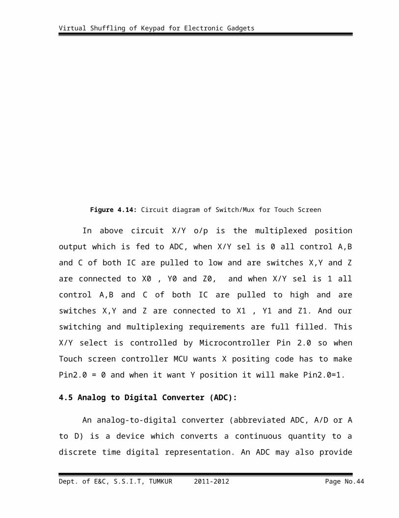
Figure 4.14: Circuit diagram of Switch/Mux for Touch Screen
In above circuit X/Y o/p is the multiplexed position output which is fed to ADC,
when X/Y sel is 0 all control A,B and C of both IC are pulled to low and are switches X,Y
and Z are connected to X0 , Y0 and Z0, and when X/Y sel is 1 all control A,B and C of both
IC are pulled to high and are switches X,Y and Z are connected to X1 , Y1 and Z1. And our
switching and multiplexing requirements are full filled. This X/Y select is controlled by
Microcontroller Pin 2.0 so when Touch screen controller MCU wants X positing code has to
make Pin2.0 = 0 and when it want Y position it will make Pin2.0=1.
4.5 Analog to Digital Converter (ADC):
An analog-to-digital converter (abbreviated ADC, A/D or A to D) is a device which
converts a continuous quantity to a discrete time digital representation. An ADC may also
provide an isolated measurement. The reverse operation is performed by a digital-to-analog
converter (DAC). Typically, an ADC is an electronic device that converts an input analog
voltage or current to a digital number proportional to the magnitude of the voltage or current.
Dept. of E&C, S.S.I.T, TUMKUR 2011-2012 Page No.29

Virtual Shuffling of Keypad for Electronic Gadgets
The Analog-to-Digital Converter (A/D Converter or ADC) has both analog and digital
functions , therefore it is a mixed-signal device.
4.5.1 Successive Approximation ADC (ADC0804):
In our project we have used ADC0804 which is Successive Approximation type of
ADC. We have used this one because it is low cost, easy to interface, widely available and
has low conversion time of 100µs.
The ADC0804 is CMOS 8-bit successive approximation A/D converters that uses a
differential potentiometric ladder similar to the 256R products. These converters are designed
to allow operation with any microcontroller or microprocessor directly driving the data bus.
These A/Ds appear like memory locations or I/O ports to the microprocessor and no
interfacing logic is needed. Differential analog voltage inputs allow increasing the common-
mode rejection and offsetting the analog zero input voltage value. In addition, the voltage
reference input can be adjusted to allow encoding any smaller analog voltage span to the full
8 bits of resolution.
4.5.2 Features:
1. Compatible with any MCU so no interfacing logic needed - access time - 135 ns
2. Easy interface to all microprocessors or microcontroller, or operates "stand alone"
3. Differential analog voltage inputs
4. Logic inputs and outputs meet both MOS and TTL voltage level specifications
5. Works with 2.5V (LM336) voltage reference
6. On-chip clock generator
7. 0V to 5V analog input voltage range with single 5V supply
8. No zero adjust required
9. 0.3[Prime] standard width 20-pin DIP package
10. 20-pin molded chip carrier or small outline package
11. Operates ratio metrically or with 5 VDC, 2.5 VDC, or analog span adjusted voltage
reference
Dept. of E&C, S.S.I.T, TUMKUR 2011-2012 Page No.30

Virtual Shuffling of Keypad for Electronic Gadgets
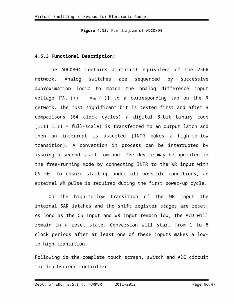
Figure 4.15: Pin diagram of ADC0804
4.5.3 Functional Description:
The ADC0804 contains a circuit equivalent of the 256R network. Analog switches
are sequenced by successive approximation logic to match the analog difference input
voltage [VIN (+) − VIN (−)] to a corresponding tap on the R network. The most significant bit
is tested first and after 8 comparisons (64 clock cycles) a digital 8-bit binary code (1111 1111
= full-scale) is transferred to an output latch and then an interrupt is asserted (INTR makes a
high-to-low transition). A conversion in process can be interrupted by issuing a second start
command. The device may be operated in the free-running mode by connecting INTR to the
WR input with CS =0. To ensure start-up under all possible conditions, an external WR pulse
is required during the first power-up cycle.
On the high-to-low transition of the WR input the internal SAR latches and the shift
register stages are reset. As long as the CS input and WR input remain low, the A/D will
remain in a reset state. Conversion will start from 1 to 8 clock periods after at least one of
these inputs makes a low-to-high transition.
Dept. of E&C, S.S.I.T, TUMKUR 2011-2012 Page No.31

Virtual Shuffling of Keypad for Electronic Gadgets
Following is the complete touch screen, switch and ADC circuit for Touchscreen controller:
Figure 4.16: Switch/Mux and ADC for Touch Screen Controller
This ADC is configure to work in interrupt mode, MCU first selects X/Y of switch
then it gives write pulse to ADC, then ADC will make INTR pin low after conversion is over
after sensing this pin low condition MCU gives RD signal and reads the digital value of X/Y
position at Port-0.
Dept. of E&C, S.S.I.T, TUMKUR 2011-2012 Page No.32
Virtual Shuffling of Keypad for Electronic Gadgets
4.6 Serial Communication and Interfacing:
Serial Communication is the process of sending one bit data at a time sequentially,
over a communication channel or computer bus. Integrated circuits are more expensive when
they have more pins. To reduce the number of pins in a package, many ICs use a serial bus to
transfer data when speed is not important. Some examples of such low-cost serial buses
include RS232, SPI, I²C, UNI/O, and 1-Wire. In this project we have used I2C bus protocol
for interfacing between different chips such as serial EEPROM and RTC, and RS232 bus
protocol for interfacing to RFID Reader, GSM Modem and PC.
4.6.1 RS-232(Recommended Standard 232):
RS-232 is an asynchronous serial transfer mechanism. The ‘RS-232’ standard includes
details of:
The protocol to be used for data transmission.
The voltages to be used on the signal lines.
The connectors to be used to link equipment together.
Overall, the standard is comprehensive and widely used, at data transfer rates of up to
around 115 or 330 kbits / second (115 / 330 k baud). Data transfer can be over distances of
15 metres or more. Figure-4.17 shows how the original data is reorganized with a start bit
added at the beginning of the data transmission and at the end, an optional parity bit, and up
to two stop bits. Also, the order of bit transmission is LSB of the data byte first and MSB of
the data byte last. Once the data to be transmitted is lined up as in Figure-4.17, it is time to
consider how it is physically transmitted over wires, what the voltage levels are, and what the
duration of each transmission is.
The transmitter and receiver of data use a fixed data rate, called the bit rate. Most
common bit rates are 300, 600, 1200, 1800, 2000, 2400, 4800, 9600, and 19200 bits per
second. Bit rate is the time for which one bit (out of the 10 or so bits) is available at the
output (or input).The bit data to be transmitted is converted to RS-232 standard voltage level
before putting it on the wires. The legal voltage limits are illustrated in Figure
Dept. of E&C, S.S.I.T, TUMKUR 2011-2012 Page No.33

Virtual Shuffling of Keypad for Electronic Gadgets
Figure 4.17: How the data is reorganized and extra bit attachments added to the original bit sequence in
asynchronous serial data transmission
Figure 4.18: Voltage levels on the RS-232 serial transmission.
In our project we have used MAX232 IC in which there are 2 Line Drivers and 2 Line
Receivers. Line Drivers converts TTL RS232 and Line Receivers converts RS232 TTL
4.6.2 I2C (Standard Inter-IC Bus):
Standard I2C devices operate up to 100kbps, while fast-mode devices operate at up to
400Kbps. I2C is appropriate for interfacing to devices on a single board, and can be stretched
across multiple boards inside a closed system, but not much further. I2C is a two-wire serial
bus, as shown in Figure-4.19. The two I2C signals are serial data (SDA) and serial clock
(SCL). Together, these signals make it possible to support serial transmission of 8-bit bytes
of data-7-bit device addresses plus control bits-over the two-wire serial bus.
Dept. of E&C, S.S.I.T, TUMKUR 2011-2012 Page No.34
Virtual Shuffling of Keypad for Electronic Gadgets
Figure 4.19: I2C two lines in total
The device that initiates a transaction on the I2C bus is termed the master. The master
normally controls the clock signal. A device being addressed by the master is called a slave.
The master transmits the device address of the intended slave at the beginning of every
transaction. Each slave is responsible for monitoring the bus and responding only to its own
address.
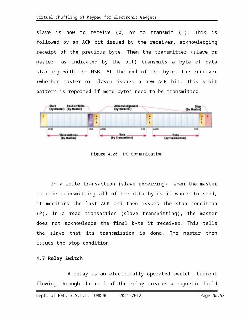
As you can see in below figure-4.20, the master begins the communication by issuing
the start condition (S). The master continues by sending a unique 7-bit slave device address,
with the most significant bit (MSB) first. The eighth bit after the start, read/not-write (),
specifies whether the slave is now to receive (0) or to transmit (1). This is followed by an
ACK bit issued by the receiver, acknowledging receipt of the previous byte. Then the
transmitter (slave or master, as indicated by the bit) transmits a byte of data starting with the
MSB. At the end of the byte, the receiver (whether master or slave) issues a new ACK bit.
This 9-bit pattern is repeated if more bytes need to be transmitted.
Figure 4.20: I2C Communication
Dept. of E&C, S.S.I.T, TUMKUR 2011-2012 Page No.35

Virtual Shuffling of Keypad for Electronic Gadgets
In a write transaction (slave receiving), when the master is done transmitting all of the
data bytes it wants to send, it monitors the last ACK and then issues the stop condition (P). In
a read transaction (slave transmitting), the master does not acknowledge the final byte it
receives. This tells the slave that its transmission is done. The master then issues the stop
condition.
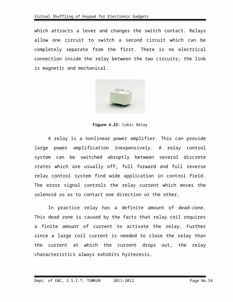
4.7 Relay Switch
A relay is an electrically operated switch. Current flowing through the coil of the relay
creates a magnetic field which attracts a lever and changes the switch contact. Relays allow
one circuit to switch a second circuit which can be completely separate from the first. There
is no electrical connection inside the relay between the two circuits; the link is magnetic and
mechanical.
Figure 4.22: Cubic Relay
A relay is a nonlinear power amplifier. This can provide large power amplification
inexpensively. A relay control system can be switched abruptly between several discrete
states which are usually off, full forward and full reverse relay control system find wide
application in control field. The error signal controls the relay current which moves the
solenoid so as to contact one direction or the other.
In practice relay has a definite amount of dead-zone. This dead zone is caused by the
facts that relay coil requires a finite amount of current to activate the relay. Further since a
large coil current is needed to close the relay than the current at which the current drops out,
the relay characteristics always exhibits hysteresis.
Dept. of E&C, S.S.I.T, TUMKUR 2011-2012 Page No.36

Virtual Shuffling of Keypad for Electronic Gadgets
5. SOFTWARE REQUIREMENTS
5.1 Flash Magic
Flash Magic is a PC tool for programming flash based microcontrollers from NXP
using a serial or Ethernet protocol while in the target hardware. In 5 simple setups one can
program the chip with cheap serial cables, it supports many devices, and it has numerous
features all the details can be obtained from http://www.flashmagictool.com/ which is official
site for Flash Magic tool.
We have used flash magic for loading programs in P89V51RD2 our microcontroller
which has serial boot loader facility following screen shots describes the method to load the
program in the chip.
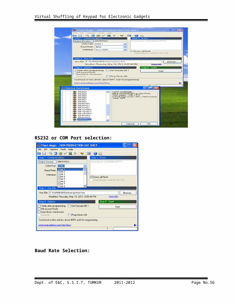
Device Selection:
Dept. of E&C, S.S.I.T, TUMKUR 2011-2012 Page No.37
Virtual Shuffling of Keypad for Electronic Gadgets
RS232 or COM Port selection:
Baud Rate Selection:
Dept. of E&C, S.S.I.T, TUMKUR 2011-2012 Page No.38

Virtual Shuffling of Keypad for Electronic Gadgets
Choosing relevant hardware configuration for our microcontroller board
Select the correct hex file which is to be loaded into the microcontroller and then click
on start you will be asked by software to reset the chip once you reset it will enter into
boot loader mode and program will be serially download in to the microcontroller.
Dept. of E&C, S.S.I.T, TUMKUR 2011-2012 Page No.39

Virtual Shuffling of Keypad for Electronic Gadgets
5.2 HyperTerminal:
HyperTerminal is an application you can use in order to connect your computer to
other remote systems. These systems include other computers, bulletin board systems,
servers, Telnet sites, and online services. However, you would need a modem, an Ethernet
connection, or a null modem cable before you can use HyperTerminal. In our case we are
using it to read and write the RS232 port of PC, the same port was used to connect to
Modem.
HyperTerminal has many features not only it sends and receives character over serial
or TCP connection it can also connect to remoter system with telnet or it can send or receive
files. In our application we use it in testing of our system by sending various strings and
numbers to PC via RS232 connection following images will guide you to setup
HyperTerminal for testing and debugging purpose.
HyperTerminal can be invoked by clicking on its icon, it is found in StartAccessories
CommunicationsHyperTerminal.
5.3 KEIL
KEIL µVision is the name of the software dedicated to the development and testing
of a family of microcontrollers based on 8051 technology, like the 89S52 which we are going
to use along this tutorial. We can download an evaluation version of KEIL at their website:
http://www.keil.com/c51/. Most versions share merely the same interface, this tutorial uses
KEIL C51 µVision 3 with the C51 compiler v8.05a.
To create a project, write and test the source code, following steps is to be followed:
Open Keil and start a new project.
Choose a name for new project, separate folder is created where all the files of
the project will be stored.
From the list at the left, seek for the brand name PHILIPS, then under
PHILIPS, select P89V51RD2. The P89V51RD2 will be called THE 'Target
device', which is the final destination of the source code.
Dept. of E&C, S.S.I.T, TUMKUR 2011-2012 Page No.40
Virtual Shuffling of Keypad for Electronic Gadgets
Click File New and then in window appeared a box named 'Text1' is present
where the code is to be written.
Click File Save as and a file name is chosen for the source code ending with
the letter '.c'.
After right-clicking on 'source group 1', click on 'Add files to group...', then
by browsing the file it is added to 'source group 1'.
HEX file is generated by right-clicking on target 1, Options for target
'target 1', then under the 'output' tab, by checking the box 'generate HEX
file'. This step is very important as the HEX file is the compiled output of the
project that is going to be transferred to the microcontroller.
Source code is to be written, then before testing the source code, we have to
compile and correct eventual syntax errors in the source code. In KEIL IDE,
this step is called 'rebuild all targets.
If after rebuilding the targets, the 'output window' shows that there is 0 error,
then test the performance of the code. In keil, like in most development
environment, this step is called Debugging.
Click on the 'Run' icon and the execution of the program will start.
Dept. of E&C, S.S.I.T, TUMKUR 2011-2012 Page No.41

Virtual Shuffling of Keypad for Electronic Gadgets
5. FLOW CHART
Dept. of E&C, S.S.I.T, TUMKUR 2011-2012 Page No.42

Virtual Shuffling of Keypad for Electronic Gadgets
6. SOURCE CODE
/* GLCD Controller */
#include<REG51F.H>
#include<string.h>
#include<stdio.h>
#include<glcd.h>
#define BUAD_1200 0xE8
#define BUAD_2400 0xF4
#define BUAD_4800 0xFA
#define BUAD_9600 0xFD
//Pin assignments for GLCD
sbit GLCD_DI = P0^0; //GLCD DATA-1/Instruction-0 Register select
pin4
sbit GLCD_RW = P0^1; //GLCD Read-1 Write-0 Select pin5
sbit GLCD_EN = P0^2; //GLCD Enable/strobe pin6
sbit GLCD_CS1 = P0^3; //GLCD Chip select 2 pin15
sbit GLCD_CS2 = P0^4; //GLCD chip select 1 pin16
sbit GLCD_RST = P0^5; //GLCD Read/Write pin17
//#define RF_BUS P2 //RF Rx Bus (MSB only)
#define GLCD_BUS P1 //GLCD 8bit DATA BUS DB0-DB7 pin7-14 1-
GND 2-VCC 19-^^^^--VCC 20-GND
Dept. of E&C, S.S.I.T, TUMKUR 2011-2012 Page No.43
Virtual Shuffling of Keypad for Electronic Gadgets
// Pin assignments for devices sbit dev_acs = P2^0;//
//Constants for GLCD
#define GLCD_Data 1
#define GLCD_Cmd 0
#define GLCD_Disp_ON 0x3F
#define GLCD_Disp_OFF 0x3E
//Software delay constants
#define XTAL 11.059200 //Crystal frequency
#define XDIVIDER 12.0 //Machine cycle Divider
#define delay_1ms 125 * (XTAL/XDIVIDER) //Counts for 1ms
void serial_init(unsigned char baud);
void delayms(unsigned int);
void delay1ms(void);
void delay_us(unsigned int);
//Graphic LCD related low level
void GLCD_write(unsigned char ,bit);
void GLCD_init();
void GLCD_clear();
void GLCD_right();
void GLCD_left();
Dept. of E&C, S.S.I.T, TUMKUR 2011-2012 Page No.44

Virtual Shuffling of Keypad for Electronic Gadgets
void GLCD_puts(unsigned char *,unsigned char,unsigned char,unsigned char);
void GLCD_putchar(unsigned char,unsigned char);
void GLCD_setxy(unsigned char,unsigned char);
//void GLCD_test();
//Display related
void WelcomeScreen();
void accessGranted();
void accessDenied();
void EnterPass();
void EnterGesture();
void Createline1();
void Createline3();
void Createline5();
void Createline7();
void CreateButton(unsigned char x,unsigned char y,unsigned char k);
void Shuffle(unsigned char);
code unsigned char TxtWelcome[]= "WELCOME TO VSK1";
code unsigned char TxtInstruct[]="SHUFFLING KEYBOARD";
code unsigned char TxtPassword[]= "Enter PASSWORD";
code unsigned char TxtPass[]= "ACCESS GRANTED";
code unsigned char TxtFail[]= "ACCESS DENIED";
Dept. of E&C, S.S.I.T, TUMKUR 2011-2012 Page No.45

Virtual Shuffling of Keypad for Electronic Gadgets
//code unsigned char TxtGesture[]= "Enter GESTURE";
//code unsigned char TxtWait[]= "PLEASE WAIT.....";
code unsigned char font5x7[] = {
0x00, 0x00, 0x00, 0x00, 0x00,// (space)
0x00, 0x00, 0x5F, 0x00, 0x00,// !
0x00, 0x07, 0x00, 0x07, 0x00,// "
0x14, 0x7F, 0x14, 0x7F, 0x14,// #
0x24, 0x2A, 0x7F, 0x2A, 0x12,// $
0x23, 0x13, 0x08, 0x64, 0x62,// %
0x36, 0x49, 0x55, 0x22, 0x50,// &
0x00, 0x05, 0x03, 0x00, 0x00,// '
0x00, 0x1C, 0x22, 0x41, 0x00,// (
0x00, 0x41, 0x22, 0x1C, 0x00,// )
0x08, 0x2A, 0x1C, 0x2A, 0x08,// *
0x08, 0x08, 0x3E, 0x08, 0x08,// +
0x00, 0x50, 0x30, 0x00, 0x00,// ,
0x08, 0x08, 0x08, 0x08, 0x08,// -
0x00, 0x30, 0x30, 0x00, 0x00,// .
0x20, 0x10, 0x08, 0x04, 0x02,// /
0x3E, 0x51, 0x49, 0x45, 0x3E,// 0
0x00, 0x42, 0x7F, 0x40, 0x00,// 1
Dept. of E&C, S.S.I.T, TUMKUR 2011-2012 Page No.46
Virtual Shuffling of Keypad for Electronic Gadgets
0x42, 0x61, 0x51, 0x49, 0x46,// 2
0x21, 0x41, 0x45, 0x4B, 0x31,// 3
0x18, 0x14, 0x12, 0x7F, 0x10,// 4
0x27, 0x45, 0x45, 0x45, 0x39,// 5
0x3C, 0x4A, 0x49, 0x49, 0x30,// 6
0x01, 0x71, 0x09, 0x05, 0x03,// 7
0x36, 0x49, 0x49, 0x49, 0x36,// 8
0x06, 0x49, 0x49, 0x29, 0x1E,// 9
0x00, 0x36, 0x36, 0x00, 0x00,// :
0x00, 0x56, 0x36, 0x00, 0x00,// ;
0x00, 0x08, 0x14, 0x22, 0x41,// <
0x14, 0x14, 0x14, 0x14, 0x14,// =
0x41, 0x22, 0x14, 0x08, 0x00,// >
0x02, 0x01, 0x51, 0x09, 0x06,// ?
0x32, 0x49, 0x79, 0x41, 0x3E,// @
0x7E, 0x11, 0x11, 0x11, 0x7E,// A
0x7F, 0x49, 0x49, 0x49, 0x36,// B
0x3E, 0x41, 0x41, 0x41, 0x22,// C
0x7F, 0x41, 0x41, 0x22, 0x1C,// D
0x7F, 0x49, 0x49, 0x49, 0x41,// E
0x7F, 0x09, 0x09, 0x01, 0x01,// F
Dept. of E&C, S.S.I.T, TUMKUR 2011-2012 Page No.47

Virtual Shuffling of Keypad for Electronic Gadgets
0x3E, 0x41, 0x41, 0x51, 0x32,// G
0x7F, 0x08, 0x08, 0x08, 0x7F,// H
0x00, 0x41, 0x7F, 0x41, 0x00,// I
0x20, 0x40, 0x41, 0x3F, 0x01,// J
0x7F, 0x08, 0x14, 0x22, 0x41,// K
0x7F, 0x40, 0x40, 0x40, 0x40,// L
0x7F, 0x02, 0x04, 0x02, 0x7F,// M
0x7F, 0x04, 0x08, 0x10, 0x7F,// N
0x3E, 0x41, 0x41, 0x41, 0x3E,// O
0x7F, 0x09, 0x09, 0x09, 0x06,// P
0x3E, 0x41, 0x51, 0x21, 0x5E,// Q
0x7F, 0x09, 0x19, 0x29, 0x46,// R
0x46, 0x49, 0x49, 0x49, 0x31,// S
0x01, 0x01, 0x7F, 0x01, 0x01,// T
0x3F, 0x40, 0x40, 0x40, 0x3F,// U
0x1F, 0x20, 0x40, 0x20, 0x1F,// V
0x7F, 0x20, 0x18, 0x20, 0x7F,// W
0x63, 0x14, 0x08, 0x14, 0x63,// X
0x03, 0x04, 0x78, 0x04, 0x03,// Y
0x61, 0x51, 0x49, 0x45, 0x43,// Z
0x00, 0x00, 0x7F, 0x41, 0x41,// [
Dept. of E&C, S.S.I.T, TUMKUR 2011-2012 Page No.48
Virtual Shuffling of Keypad for Electronic Gadgets
0x02, 0x04, 0x08, 0x10, 0x20,// "\"
0x41, 0x41, 0x7F, 0x00, 0x00,// ]
0x04, 0x02, 0x01, 0x02, 0x04,// ^
0x40, 0x40, 0x40, 0x40, 0x40,// _
0x00, 0x01, 0x02, 0x04, 0x00,// `
0x20, 0x54, 0x54, 0x54, 0x78,// a
0x7F, 0x48, 0x44, 0x44, 0x38,// b
0x38, 0x44, 0x44, 0x44, 0x20,// c
0x38, 0x44, 0x44, 0x48, 0x7F,// d
0x38, 0x54, 0x54, 0x54, 0x18,// e
0x08, 0x7E, 0x09, 0x01, 0x02,// f
0x08, 0x14, 0x54, 0x54, 0x3C,// g
0x7F, 0x08, 0x04, 0x04, 0x78,// h
0x00, 0x44, 0x7D, 0x40, 0x00,// i
0x20, 0x40, 0x44, 0x3D, 0x00,// j
0x00, 0x7F, 0x10, 0x28, 0x44,// k
0x00, 0x41, 0x7F, 0x40, 0x00,// l
0x7C, 0x04, 0x18, 0x04, 0x78,// m
0x7C, 0x08, 0x04, 0x04, 0x78,// n
0x38, 0x44, 0x44, 0x44, 0x38,// o
0x7C, 0x14, 0x14, 0x14, 0x08,// p
Dept. of E&C, S.S.I.T, TUMKUR 2011-2012 Page No.49

Virtual Shuffling of Keypad for Electronic Gadgets
0x08, 0x14, 0x14, 0x18, 0x7C,// q
0x7C, 0x08, 0x04, 0x04, 0x08,// r
0x48, 0x54, 0x54, 0x54, 0x20,// s
0x04, 0x3F, 0x44, 0x40, 0x20,// t
0x3C, 0x40, 0x40, 0x20, 0x7C,// u
0x1C, 0x20, 0x40, 0x20, 0x1C,// v
0x3C, 0x40, 0x30, 0x40, 0x3C,// w
0x44, 0x28, 0x10, 0x28, 0x44,// x
0x0C, 0x50, 0x50, 0x50, 0x3C,// y
0x44, 0x64, 0x54, 0x4C, 0x44,// z
0x00, 0x08, 0x36, 0x41, 0x00,// {
0x00, 0x00, 0x7F, 0x00, 0x00,// |
0x00, 0x41, 0x36, 0x08, 0x00,// }
0x08, 0x08, 0x2A, 0x1C, 0x08,// ->
0x08, 0x1C, 0x2A, 0x08, 0x08, // <-
0xff, 0xff, 0xff, 0xff, 0xff,
};
//Global
unsigned char xp,pswd[5]="3591";
unsigned char cur_comb=0;
unsigned char key_cur[12]={'1','2','3','4','5','6','7','8','9','0','Y','N'};
Dept. of E&C, S.S.I.T, TUMKUR 2011-2012 Page No.50

Virtual Shuffling of Keypad for Electronic Gadgets
code unsigned char key_shuffle[16][12]=
{
'1','2','3','4','5','6','7','8','9','0','Y','N',
'2','1','4','3','6','5','8','7','0','9','N','Y',
'3','2','1','6','5','4','9','7','8','N','Y','0',
'4','3','2','1','7','8','6','5','N','Y','0','9',
'1','5','8','Y','2','4','3','6','9','N','7','0',
'2','6','9','N','3','5','4','7','0','1','8','Y',
'3','7','0','1','4','6','5','8','Y','2','9','N',
'4','8','Y','2','5','7','6','9','N','3','0','1',
'5','9','N','3','6','8','7','0','1','4','Y','2',
'6','0','1','4','7','9','8','Y','2','5','N','3',
'7','Y','2','5','8','0','9','N','3','6','1','4',
'8','N','3','4','9','Y','0','1','6','7','2','5',
'9','1','4','5','0','N','Y','2','7','8','3','6',
'0','2','5','8','Y','1','N','3','6','9','4','7',
'Y','3','6','7','N','2','1','4','9','0','5','8',
'N','4','7','0','1','3','2','5','8','Y','6','9',
};
Dept. of E&C, S.S.I.T, TUMKUR 2011-2012 Page No.51

Virtual Shuffling of Keypad for Electronic Gadgets
//Global variable
unsigned char ser_data;
bit ser_rx=0;
void serial_rx(void) interrupt 4 using 1
{
if(RI)
{
RI=0;
if((SBUF>='A')&&(SBUF<='L'))
{
ser_data=SBUF-'A';
ser_rx=1;
}
}
if(TI)
TI=0;
}
void main()
{
unsigned char key_inp[5],key_count=0;
bit refresh=0,wake_up=1;
Dept. of E&C, S.S.I.T, TUMKUR 2011-2012 Page No.52
Virtual Shuffling of Keypad for Electronic Gadgets
dev_acs=0;
GLCD_init();
WelcomeScreen();
delayms(2000);
GLCD_init();
WelcomeScreen();
serial_init(BUAD_9600);
cur_comb=5;
//GLCD_clear();
while(1)
{
if(ser_rx)
{
ser_rx=0;
if(wake_up)
{
wake_up=0;
refresh=1; //Open up keyboard
}
Dept. of E&C, S.S.I.T, TUMKUR 2011-2012 Page No.53
Virtual Shuffling of Keypad for Electronic Gadgets
else
{
key_inp[key_count]=key_cur[ser_data];
//GLCD_left();
//GLCD_setxy(0,20);
//GLCD_putchar(key_inp[key_count],0);
key_count++;
if(key_count==4)
{
key_inp[key_count]=0x00;
ES=0;
key_count=0;
if(strcmp(key_inp,pswd)==0)
{
dev_acs=1;
accessGranted();
delayms(5000);
dev_acs=0;
}
else
{
Dept. of E&C, S.S.I.T, TUMKUR 2011-2012 Page No.54

Virtual Shuffling of Keypad for Electronic Gadgets
accessDenied();
delayms(2000);
}
WelcomeScreen();
wake_up=1;
RI=0;
ES=1;
}
}
}
if(refresh==1)
{
refresh=0;
Shuffle(cur_comb);
cur_comb++;
if(cur_comb==16)
cur_comb=0;
}
}
}
Dept. of E&C, S.S.I.T, TUMKUR 2011-2012 Page No.55
Virtual Shuffling of Keypad for Electronic Gadgets
void Shuffle(unsigned char comb)
{
unsigned char i;
EnterPass();
GLCD_left();
GLCD_setxy(0,0);
xp=0;
GLCD_putchar('0'+comb,0);//key layout no
for(i=0;i<12;i++)
key_cur[i]=key_shuffle[comb][i];
for(i=0;i<12;i++)
CreateButton((i%4+1),(i/4)*2,key_cur[i]); //CreateButton1(k1);
//CreateButton2(k2);//CreateButton3(k3);
}
void WelcomeScreen()
{
GLCD_clear();
GLCD_left();
GLCD_puts(TxtWelcome,(unsigned char)strlen(TxtWelcome),15,3);
GLCD_puts(TxtInstruct,(unsigned char)strlen(TxtInstruct),15,5);
}
Dept. of E&C, S.S.I.T, TUMKUR 2011-2012 Page No.56

Virtual Shuffling of Keypad for Electronic Gadgets
void accessGranted()
{
GLCD_clear();
GLCD_left();
GLCD_puts(TxtPass,(unsigned char)strlen(TxtPass),15,4);
//GLCD_puts(TxtInstruct,(unsigned char)strlen(TxtInstruct),15,5);
}
void accessDenied()
{
GLCD_clear();
GLCD_left();
GLCD_puts(TxtFail,(unsigned char)strlen(TxtFail),15,4);
//GLCD_puts(TxtInstruct,(unsigned char)strlen(TxtInstruct),15,5);
}
void EnterPass()
{
GLCD_clear();
GLCD_left();
GLCD_puts(TxtPassword,(unsigned char)strlen(TxtPassword),25,0);
Createline1();
Createline3();
Dept. of E&C, S.S.I.T, TUMKUR 2011-2012 Page No.57

Virtual Shuffling of Keypad for Electronic Gadgets
Createline5();
Createline7();
}//0 32
void CreateButton(unsigned char x,unsigned char y,unsigned char k)
{
unsigned int i;
if(x<=2)
GLCD_left();
else
GLCD_right();
switch(x)
{
case 1: x=0;
break;
case 2: x=32;
break;
case 3: x=0;
break;
case 4: x=32;
break;
}
Dept. of E&C, S.S.I.T, TUMKUR 2011-2012 Page No.58

Virtual Shuffling of Keypad for Electronic Gadgets
//Line 2 (Text line)
GLCD_setxy(x,y+2);
for(i=0;i<(6*1);i++)
{
GLCD_write(0x00,GLCD_Data);
}
for(i=0;i<(5*1);i++)
{
GLCD_write(0xff,GLCD_Data);
}
//Digit
GLCD_write(0x00,GLCD_Data);
GLCD_write(0x00,GLCD_Data);
xp=0;
GLCD_putchar(k,y+2);
GLCD_write(0x00,GLCD_Data);
GLCD_write(0x00,GLCD_Data);
for(i=0;i<(5*1);i++)
{
GLCD_write(0xff,GLCD_Data);
} }
Dept. of E&C, S.S.I.T, TUMKUR 2011-2012 Page No.59

Virtual Shuffling of Keypad for Electronic Gadgets
//LINE 1
void Createline1()
{
unsigned int i;
GLCD_left();
//line1 digit 1st
GLCD_setxy(0,1);
for(i=0;i<(6*1);i++)
{
GLCD_write(0x00,GLCD_Data);
}
for(i=0;i<(5*1);i++)
{
GLCD_write(0xfc,GLCD_Data);
}
for(i=0;i<(9*1);i++)
{
GLCD_write(0x3c,GLCD_Data);
}
for(i=0;i<(5*1);i++)
{
Dept. of E&C, S.S.I.T, TUMKUR 2011-2012 Page No.60

Virtual Shuffling of Keypad for Electronic Gadgets
GLCD_write(0xfc,GLCD_Data);
}
//line1 digit 2nd
GLCD_setxy(32,1);
for(i=0;i<(6*1);i++)
{
GLCD_write(0x00,GLCD_Data);
}
for(i=0;i<(5*1);i++)
{
GLCD_write(0xfc,GLCD_Data);
}
for(i=0;i<(9*1);i++)
{
GLCD_write(0x3c,GLCD_Data);
}
for(i=0;i<(5*1);i++)
{
GLCD_write(0xfc,GLCD_Data);
}
Dept. of E&C, S.S.I.T, TUMKUR 2011-2012 Page No.61

Virtual Shuffling of Keypad for Electronic Gadgets
GLCD_right();
//line1 Digit 3rd
GLCD_setxy(0,1);
for(i=0;i<(6*1);i++)
{
GLCD_write(0x00,GLCD_Data);
}
for(i=0;i<(5*1);i++)
{
GLCD_write(0xfc,GLCD_Data);
}
for(i=0;i<(9*1);i++)
{
GLCD_write(0x3c,GLCD_Data);
}
for(i=0;i<(5*1);i++)
{
GLCD_write(0xfc,GLCD_Data);
}
Dept. of E&C, S.S.I.T, TUMKUR 2011-2012 Page No.62

Virtual Shuffling of Keypad for Electronic Gadgets
//line1 Digit 4th
GLCD_setxy(32,1);
for(i=0;i<(6*1);i++)
{
GLCD_write(0x00,GLCD_Data);
}
for(i=0;i<(5*1);i++)
{
GLCD_write(0xfc,GLCD_Data);
}
for(i=0;i<(9*1);i++)
{
GLCD_write(0x3c,GLCD_Data);
}
for(i=0;i<(5*1);i++)
{
GLCD_write(0xfc,GLCD_Data);
}
}
Dept. of E&C, S.S.I.T, TUMKUR 2011-2012 Page No.63
Virtual Shuffling of Keypad for Electronic Gadgets
//LINE 3
void Createline3()
{
unsigned int i;
GLCD_left();
//line 3 digit 1st
GLCD_setxy(0,3);
for(i=0;i<(6*1);i++)
{
GLCD_write(0x00,GLCD_Data);
}
for(i=0;i<(5*1);i++)
{
GLCD_write(0xf3,GLCD_Data);
}
for(i=0;i<(9*1);i++)
{
GLCD_write(0x33,GLCD_Data);
}
for(i=0;i<(5*1);i++)
{
Dept. of E&C, S.S.I.T, TUMKUR 2011-2012 Page No.64
Virtual Shuffling of Keypad for Electronic Gadgets
GLCD_write(0xf3,GLCD_Data);
}
//line 3 digit 2nd
GLCD_setxy(32,3);
for(i=0;i<(6*1);i++)
{
GLCD_write(0x00,GLCD_Data);
}
for(i=0;i<(5*1);i++)
{
GLCD_write(0xf3,GLCD_Data);
}
for(i=0;i<(9*1);i++)
{
GLCD_write(0x33,GLCD_Data);
}
for(i=0;i<(5*1);i++)
{
GLCD_write(0xf3,GLCD_Data);
}
Dept. of E&C, S.S.I.T, TUMKUR 2011-2012 Page No.65
Virtual Shuffling of Keypad for Electronic Gadgets
GLCD_right();
//line 3 digit 3rd
GLCD_setxy(0,3);
for(i=0;i<(6*1);i++)
{
GLCD_write(0x00,GLCD_Data);
}
for(i=0;i<(5*1);i++)
{
GLCD_write(0xf3,GLCD_Data);
}
for(i=0;i<(9*1);i++)
{
GLCD_write(0x33,GLCD_Data);
}
for(i=0;i<(5*1);i++)
{
GLCD_write(0xf3,GLCD_Data);
}
Dept. of E&C, S.S.I.T, TUMKUR 2011-2012 Page No.66
Virtual Shuffling of Keypad for Electronic Gadgets
//line 3 digit 4th
GLCD_setxy(32,3);
for(i=0;i<(6*1);i++)
{
GLCD_write(0x00,GLCD_Data);
}
for(i=0;i<(5*1);i++)
{
GLCD_write(0xf3,GLCD_Data);
}
for(i=0;i<(9*1);i++)
{
GLCD_write(0x33,GLCD_Data);
}
for(i=0;i<(5*1);i++)
{
GLCD_write(0xf3,GLCD_Data);
}
}
Dept. of E&C, S.S.I.T, TUMKUR 2011-2012 Page No.67

Virtual Shuffling of Keypad for Electronic Gadgets
//LINE 5
void Createline5()
{
unsigned int i;
GLCD_left();
//Line 5 digit 1st
GLCD_setxy(0,5);
for(i=0;i<(6*1);i++)
{
GLCD_write(0x00,GLCD_Data);
}
for(i=0;i<(5*1);i++)
{
GLCD_write(0xf3,GLCD_Data);
}
for(i=0;i<(9*1);i++)
{
GLCD_write(0x33,GLCD_Data);
}
for(i=0;i<(5*1);i++)
{
Dept. of E&C, S.S.I.T, TUMKUR 2011-2012 Page No.68
Virtual Shuffling of Keypad for Electronic Gadgets
GLCD_write(0xf3,GLCD_Data);
}
//Line 5 digit 2nd
GLCD_setxy(32,5);
for(i=0;i<(6*1);i++)
{
GLCD_write(0x00,GLCD_Data);
}
for(i=0;i<(5*1);i++)
{
GLCD_write(0xf3,GLCD_Data);
}
for(i=0;i<(9*1);i++)
{
GLCD_write(0x33,GLCD_Data);
}
for(i=0;i<(5*1);i++)
{
GLCD_write(0xf3,GLCD_Data);
}
Dept. of E&C, S.S.I.T, TUMKUR 2011-2012 Page No.69

Virtual Shuffling of Keypad for Electronic Gadgets
GLCD_right();
//Line 5 digit 3rd
GLCD_setxy(0,5);
for(i=0;i<(6*1);i++)
{
GLCD_write(0x00,GLCD_Data);
}
for(i=0;i<(5*1);i++)
{
GLCD_write(0xf3,GLCD_Data);
}
for(i=0;i<(9*1);i++)
{
GLCD_write(0x33,GLCD_Data);
}
for(i=0;i<(5*1);i++)
{
GLCD_write(0xf3,GLCD_Data);
}
Dept. of E&C, S.S.I.T, TUMKUR 2011-2012 Page No.70
Virtual Shuffling of Keypad for Electronic Gadgets
//Line 5 digit 4th
GLCD_setxy(32,5);
for(i=0;i<(6*1);i++)
{
GLCD_write(0x00,GLCD_Data);
}
for(i=0;i<(5*1);i++)
{
GLCD_write(0xf3,GLCD_Data);
}
for(i=0;i<(9*1);i++)
{
GLCD_write(0x33,GLCD_Data);
}
for(i=0;i<(5*1);i++)
{
GLCD_write(0xf3,GLCD_Data);
}
}
Dept. of E&C, S.S.I.T, TUMKUR 2011-2012 Page No.71
Virtual Shuffling of Keypad for Electronic Gadgets
//LINE 8
void Createline7()
{
unsigned int i;
GLCD_left();
//Line 8 digit 1st
GLCD_setxy(0,7);
for(i=0;i<(6*1);i++)
{
GLCD_write(0x00,GLCD_Data);
}
for(i=0;i<(19*1);i++)
{
GLCD_write(0x07,GLCD_Data);
}
//Line 8 digit 2nd
GLCD_setxy(32,7);
for(i=0;i<(6*1);i++)
{
GLCD_write(0x00,GLCD_Data);
}
Dept. of E&C, S.S.I.T, TUMKUR 2011-2012 Page No.72

Virtual Shuffling of Keypad for Electronic Gadgets
for(i=0;i<(19*1);i++)
{
GLCD_write(0x07,GLCD_Data);
}
GLCD_right();
//Line 8 digit 3rd
GLCD_setxy(0,7);
for(i=0;i<(6*1);i++)
{
GLCD_write(0x00,GLCD_Data);
}
for(i=0;i<(19*1);i++)
{
GLCD_write(0x07,GLCD_Data);
}
//Line 8 digit 4th
GLCD_setxy(32,7);
for(i=0;i<(6*1);i++)
{
GLCD_write(0x00,GLCD_Data);
}
Dept. of E&C, S.S.I.T, TUMKUR 2011-2012 Page No.73

Virtual Shuffling of Keypad for Electronic Gadgets
for(i=0;i<(19*1);i++)
{
GLCD_write(0x07,GLCD_Data);
} }
void GLCD_puts(unsigned char *str,unsigned char len,unsigned char x,unsigned char y)
{
unsigned char i,x1;
if(x<63)
GLCD_left();
else
GLCD_right();
x=x+0x40;
xp=x;
y=y+0xB8;
x1=x + (12 - (x-0x40)/5);
GLCD_write(x,GLCD_Cmd);
GLCD_write(y,GLCD_Cmd);
for(i=0;i<len;i++,x++)
{
GLCD_putchar(str[i],y); }
GLCD_write(GLCD_Disp_ON,GLCD_Cmd);
Dept. of E&C, S.S.I.T, TUMKUR 2011-2012 Page No.74

Virtual Shuffling of Keypad for Electronic Gadgets
}
void GLCD_putchar(unsigned char c,unsigned char y)
{
unsigned char i;
unsigned int a;
a=(c-0x20)*5;
for(i=0;i<5;i++,xp++)
{
if(xp==128)
{
xp=0x40;
GLCD_write(GLCD_Disp_ON,GLCD_Cmd);
GLCD_right();
GLCD_write(GLCD_Disp_OFF,GLCD_Cmd);
GLCD_write(0x40,GLCD_Cmd);
GLCD_write(y,GLCD_Cmd);
GLCD_write(GLCD_Disp_ON,GLCD_Cmd);
}
if(xp==1)
xp=0;
GLCD_write(font5x7[a++],GLCD_Data);
}
Dept. of E&C, S.S.I.T, TUMKUR 2011-2012 Page No.75

Virtual Shuffling of Keypad for Electronic Gadgets
//printf("\nx2=%d",(int)x);
}
void GLCD_left()
{
GLCD_CS2=0;
GLCD_CS1=1;
}
void GLCD_right()
{
GLCD_CS2=1;
GLCD_CS1=0;
}
//Clear GLCD
void GLCD_clear()
{
unsigned char i;
unsigned char j;
GLCD_write(GLCD_Disp_OFF,GLCD_Cmd);
GLCD_left();
for(j=0xB8;j<0xC0;j++)
{
Dept. of E&C, S.S.I.T, TUMKUR 2011-2012 Page No.76
Virtual Shuffling of Keypad for Electronic Gadgets
GLCD_write(0x40,GLCD_Cmd);
GLCD_write(j,GLCD_Cmd);
for(i=0;i<64;i++)
GLCD_write(0x00,GLCD_Data);
}
GLCD_right();
for(j=0xB8;j<0xC0;j++)
{
GLCD_write(0x40,GLCD_Cmd);
GLCD_write(j,GLCD_Cmd);
for(i=0;i<64;i++)
GLCD_write(0x00,GLCD_Data);
}
GLCD_write(GLCD_Disp_ON,GLCD_Cmd);
}
//Init serial port for given baud rate
void serial_init(unsigned char baud)
{
SCON = 0x50; /* SCON: mode 1, 8-bit UART, enable reciever */
TMOD = 0x20; /* TMOD: timer 1, mode 2, 8-bit reload */
TH1 = baud; /* TH1: argument BAUD_XXXX @ 11.0592MHz */
Dept. of E&C, S.S.I.T, TUMKUR 2011-2012 Page No.77
Virtual Shuffling of Keypad for Electronic Gadgets
TL1 = baud;
TR1 = 1; /* TR1: timer 1 run */
TI = 0; /* TI: set TI to send first char of UART */
RI = 0;
EA =1;
ES = 1;
}
void delayms(unsigned int m)
{
for(;m!=0x00;m--)
delay1ms();
}
void delay1ms(void)
{
unsigned int n = delay_1ms;
for (;n!=0x00;n--);
}
void delay_us(unsigned int u)
{
for (;u!=0x00;u--);
}
Dept. of E&C, S.S.I.T, TUMKUR 2011-2012 Page No.78

Virtual Shuffling of Keypad for Electronic Gadgets
8. ADVANTAGES & DISADVANTAGES
8.1 Advantages:
1. Keypad based access or security systems are prone to password leaks in various ways
and this is improved to great extent in our security system.
2. As we use the ATM, after every transaction the keypad arrangements will get change
which makes confusion to the thief to guess the pin codes.
3. As the key pad get shuffle after every use the developed access system is more secure
as compared with the existing ATM access system.
4. We can use this shuffling keypad access system for defense applications where the
existing keypad access system can be replaced with this shuffling system.
5. For defense so many weapon rooms are there to store missiles, arms, guns etc where
they use normal keypad access system, which is prone to password leaks. Using
shuffling keypad it can be made more secured.
8.2 Disadvantages:
1. The shuffling keypad system is costlier as compared to the existing access system.
2. Here the use of touch screen interface makes the system more complex as we have to
write the more complex algorithms to process the data to the controller.
Dept. of E&C, S.S.I.T, TUMKUR 2011-2012 Page No.79
Virtual Shuffling of Keypad for Electronic Gadgets
9. APPLICATIONS AND FUTURE SCOPE
9.1 Applications:
1. Security systems are playing a important role in present world and it will keep on
growing in US almost every house has some sort of Security or Alarm system, our
system has straight forward use wherever security is required.
2. Use in Access control system, in many places, companies, or organizations some
regions are restricted and its access is limited to authorized personals only in such
places our system is very useful. Only one or two gestures we make on screen and we
are allowed to go in secured area.
3. In bank lockers, electronic safe and similar our system is can be used because of its
compact size and easy interface.
4. In defense so many weapons rooms are there, missiles, tanks, air craft for all of them
code locks are there which can be replaced by our security system.
9.2 Future Scope:
1. By adding the GSM technology a SMS can be sent to the mobile of the respective
card holders if that ATMs password is entered wrongly three times.
2. Even it can be synchronized with the local server which can generate an e-mail and
send it to the respective card holders.
Dept. of E&C, S.S.I.T, TUMKUR 2011-2012 Page No.80

Virtual Shuffling of Keypad for Electronic Gadgets
10.CONCLUSION
The virtual shuffling of keypad would lead to a more secure authentication of the use
of password in ATM’s or any other electronic gadgets. This can lead to decrease in theft of
important materials like money in ATM’s or in bank lockers. This method can provide a
great help for the people in day to day life.
With the implementation of this prototype, it will lead to a great technological
advancement. This project will overcome the loophole which prevails in the current system.
This will cease the increase in the day to day thefts. It can also be used by the countries to
protect their arms and ammunitions which will safeguard their respective countries from
being targeted by their enemies.
Thus taking the above advantages into the consideration, the sooner it gets
implemented the better it is for the society. This prototype if implemented, it will prove to be
a stepping stone in the 21st century. Hence it provides a greater authentication to the module.
Dept. of E&C, S.S.I.T, TUMKUR 2011-2012 Page No.81
Virtual Shuffling of Keypad for Electronic Gadgets
11. BIBLIOGRAPHY
[1] http://ieeexplore.ieee.org/xpl/freeabs_all.jsp?arnumber=1037318
[2] http://ieeexplore.ieee.org/iel5/30/5505923/05506047.pdf%3Farnumber%3D5506047&sa=U&ei=-
6_wTrb0JO-gmQXS0NWAAg&ved=0CAgQFjAC&client=internal-uds-cse&usg=AFQjCNHmF6oOjVLWlm-
Q_zMf88v50V1rsg
[3] The 8051 Microcontroller by Kenneth J. Ayala
[4] I2C Manual: http://www.nxp.com/documents/application_note/AN10216.pdf
[5] I2C Serial EEPROM Interfacing: www.atmel.com/atmel/acrobat/doc0507.pdf
[6] www.keil.com/c51/
[7] The 8051 microcontroller by I. Scott MacKenzie, Raphael C.-W. Phan.
[8] C and the 8051 by Thomas W. Schultz
Dept. of E&C, S.S.I.T, TUMKUR 2011-2012 Page No.82

Virtual Shuffling of Keypad for Electronic Gadgets
SNAPSHOT
Dept. of E&C, S.S.I.T, TUMKUR 2011-2012 Page No.83