sheet metal rolling using two roller...
TRANSCRIPT
IJITE Vol.04 Issue-01, (January, 2016) ISSN: 2321-1776 International Journal in IT and Engineering, Impact Factor- 4.747
A Monthly Double-Blind Peer Reviewed Refereed Open Access International e-Journal - Included in the International Serial Directories
International Journal in IT and Engineering http://www.ijmr.net.in email id- [email protected] Page 1
SHEET METAL ROLLING USING TWO ROLLER POWERED MACHINE
V.Deepika Satya Bhanu
P.G Student,
Department of Mechanical Engineering,
Sri Indu College of Engineering & Technology,
Hyderabad, India.
Dr P Mallesham
Principal,
Department Mechanical Engineering,
Sri Indu College of Engineering & Technology,
Hyderabad, India
ABSTRACT
In Sheet Metal working industry a wide range of power and hand
operated machines are being used. As the sheet metal industry is a
large and growing industry different types of machines are used for
different operations. Rolling is a fabricating process in which the
metal, plastic, paper, glass, etc. is passed through a pair (or pairs)
of rolls. There are two types of rolling process, flat and profile
rolling. In flat rolling the final shape of the product is either
classed as sheet (typically thickness less than 3 mm, also called
"strip") or plate (typically thickness more than 3 mm). In profile
rolling the final product may be a round rod or other shaped bar,
such as a structural section (beam, channel, joist etc). In this study,
different metals are been rolled by using two roller electrically
powered rolling machine and its properties are being analyzed.
The influence of rolling process parameters such as sheet
thickness, sheet width, , Elongation, Reduction in thickness on the
Strip and shape and its profile have been investigated.
KEYWORDS
Electrically powered machine, Roll Pass Design Calculations,
Strain calculations.
INTRODUCTION
Sheet Metal industry is a large and growing industry. There are
many special purposes machines used in this industry to-day. The
proper selection of the machines depends upon the type of the work
under-taken by the particular industry. There are many examples of
Sheet Metal work, which can be seen in our everyday lives. The
metals generally used for Sheet Metal work include black iron
sheet, copper sheet, tin plate, aluminum plate, stainless sheet and
brass sheet.
My project the “SHEET METAL ROLLING USING TWO
ROLLER POWERED MACHINE” finds huge application in Sheet
Metal industry. Rolling is a metal forming process in
which metal stock is passed through one or more pairs of rolls to
reduce the thickness and to make the thickness uniform. Rolling
operation can be done on hand or power operated rolling machines.
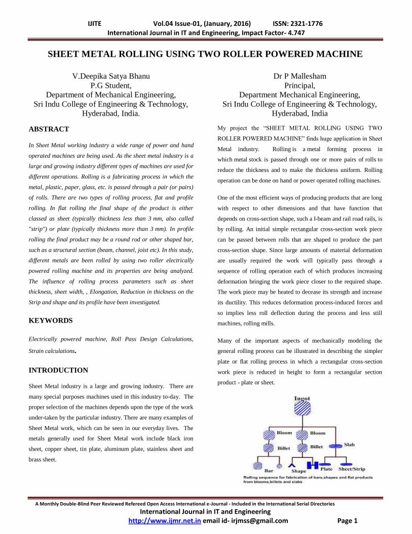
One of the most efficient ways of producing products that are long
with respect to other dimensions and that have function that
depends on cross-section shape, such a I-beam and rail road rails, is
by rolling. An initial simple rectangular cross-section work piece
can be passed between rolls that are shaped to produce the part
cross-section shape. Since large amounts of material deformation
are usually required the work will typically pass through a
sequence of rolling operation each of which produces increasing
deformation bringing the work piece closer to the required shape.
The work piece may be heated to decease its strength and increase
its ductility. This reduces deformation process-induced forces and
so implies less roll deflection during the process and less still
machines, rolling mills.
Many of the important aspects of mechanically modeling the
general rolling process can be illustrated in describing the simpler
plate or flat rolling process in which a rectangular cross-section
work piece is reduced in height to form a rectangular section
product - plate or sheet.

IJITE Vol.04 Issue-01, (January, 2016) ISSN: 2321-1776 International Journal in IT and Engineering, Impact Factor- 4.747
A Monthly Double-Blind Peer Reviewed Refereed Open Access International e-Journal - Included in the International Serial Directories
International Journal in IT and Engineering http://www.ijmr.net.in email id- [email protected] Page 2
GRAIN STRUCTURE IN ROLLING
When the wrought or cast product gets hot rolled, the grain
structure, which is coarse grained, becomes finer in size, but
elongated along the direction of rolling. This type of textured grain
structure results in directional property [anisotropy] for the rolled
product. In order to refine the grains, heat treatment is performed
immediately after rolling, which results in recrystallization after
rolling.
Fig 2 Grain structure
FORMING PROCESS
Forming processes are those in which the shape of a
metal piece is changed by plastic deformation .Forming processes
are commonly classified into hot-working and cold-working
operations.
Typical forming processes are:
Rolling
Extrusion
Forging
Drawing
ROLLING
Rolling is a process of reduction of the cross-sectional
area or shaping a metal piece through the deformation caused by a
pair of rotating in opposite directions metal rolls.
Rolling is the plastic deformation of materials caused by
compressive force applied through a set of rolls. The cross section
of the work piece is reduced by the process. The material gets
squeezed between a pair of rolls, as a result of which the thickness
gets reduced and the length gets increased.
A machine used for rolling metal is called rolling mill. A typical
rolling mill consists of a pair of rolls driven by an electric motor
transmitting a torque through a gear and pair of cardans. The rolls
are equipped with bearings and mounted in a stand with a screw-
down mechanism.
Fig 3 Rolling Mill
BASIC ROLLING PROCESS
• Heated metal is passed between two rolls that rotate in
opposite directions
• Gap between rolls is less than thickness of entering metal
Rolls rotate with surface velocity that exceeds speed of
incoming metal, friction along the contact interface acts
to propel the metal forward.
• Metal is squeezed and elongates result in decrease of the
cross-sectional area.
• Amount of deformation in a single pass depends on the
friction conditions along the interface.
• If too much material flow is demanded, rolls cannot
advance the material and simply skid over its surface.
Too little deformation per pass results in excessive
production cost.
IJITE Vol.04 Issue-01, (January, 2016) ISSN: 2321-1776 International Journal in IT and Engineering, Impact Factor- 4.747
A Monthly Double-Blind Peer Reviewed Refereed Open Access International e-Journal - Included in the International Serial Directories
International Journal in IT and Engineering http://www.ijmr.net.in email id- [email protected] Page 3
DESCRIPTION OF THE MACHINE
The Sheet Metal Rolling Machine works according to the principle
of two point bending. The rotation of the driven rolls being utilized
to feed the metal through the rolls by means of the frictional forces
present between the surface of the rolls and sheet. No lubricant is
used at its presence interference with the ability to grip. Sheet
Metal Rolling Machine essentially consists of two rollers, used to
manufacture circular components like cylinders. Sheet Metal
Rolling Machine is classified into two types based on the
arrangement of the rollers. They are as follows.
1. Pinch type machine
2. Pyramidal type machine
This machine is of pyramidal type here only the bottom roll is
driven the top roll serves as an idler and rotates on friction with the
work metal blank.
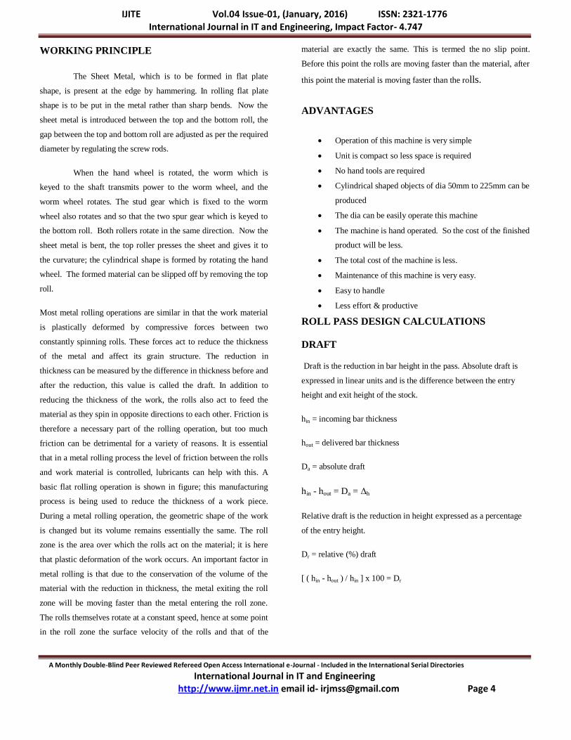
MANUAL ROLLING MACHINE
Fig 4 Manual Rolling Machine
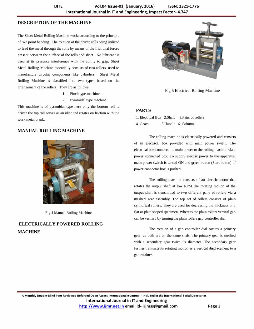
ELECTRICALLY POWERED ROLLING
MACHINE
Fig 5 Electrical Rolling Machine
PARTS
1. Electrical Box 2.Shaft 3.Pairs of rollers
4. Gears 5.Handle 6. Column
The rolling machine is electrically powered and consists
of an electrical box provided with main power switch. The
electrical box connects the main power to the rolling machine via a
power connected box. To supply electric power to the apparatus,
main power switch is turned ON and green button (Start button) of
power connector box is pushed.
The rolling machine consists of an electric motor that
rotates the output shaft at low RPM.The rotating motion of the
output shaft is transmitted to two different pairs of rollers via a
meshed gear assembly. The top set of rollers consists of plain
cylindrical rollers. They are used for decreasing the thickness of a
flat or plate shaped specimen. Whereas the plain rollers vertical gap
can be verified by turning the plain rollers gap controller dial.
The rotation of a gap controller dial rotates a primary
gear, as both are on the same shaft. The primary gear is meshed
with a secondary gear twice its diameter. The secondary gear
further transmits its rotating motion as a vertical displacement to a
gap retainer.
IJITE Vol.04 Issue-01, (January, 2016) ISSN: 2321-1776 International Journal in IT and Engineering, Impact Factor- 4.747
A Monthly Double-Blind Peer Reviewed Refereed Open Access International e-Journal - Included in the International Serial Directories
International Journal in IT and Engineering http://www.ijmr.net.in email id- [email protected] Page 4
WORKING PRINCIPLE
The Sheet Metal, which is to be formed in flat plate
shape, is present at the edge by hammering. In rolling flat plate
shape is to be put in the metal rather than sharp bends. Now the
sheet metal is introduced between the top and the bottom roll, the
gap between the top and bottom roll are adjusted as per the required
diameter by regulating the screw rods.
When the hand wheel is rotated, the worm which is
keyed to the shaft transmits power to the worm wheel, and the
worm wheel rotates. The stud gear which is fixed to the worm
wheel also rotates and so that the two spur gear which is keyed to
the bottom roll. Both rollers rotate in the same direction. Now the
sheet metal is bent, the top roller presses the sheet and gives it to
the curvature; the cylindrical shape is formed by rotating the hand
wheel. The formed material can be slipped off by removing the top
roll.
Most metal rolling operations are similar in that the work material
is plastically deformed by compressive forces between two
constantly spinning rolls. These forces act to reduce the thickness
of the metal and affect its grain structure. The reduction in
thickness can be measured by the difference in thickness before and
after the reduction, this value is called the draft. In addition to
reducing the thickness of the work, the rolls also act to feed the
material as they spin in opposite directions to each other. Friction is
therefore a necessary part of the rolling operation, but too much
friction can be detrimental for a variety of reasons. It is essential
that in a metal rolling process the level of friction between the rolls
and work material is controlled, lubricants can help with this. A
basic flat rolling operation is shown in figure; this manufacturing
process is being used to reduce the thickness of a work piece.
During a metal rolling operation, the geometric shape of the work
is changed but its volume remains essentially the same. The roll
zone is the area over which the rolls act on the material; it is here
that plastic deformation of the work occurs. An important factor in
metal rolling is that due to the conservation of the volume of the
material with the reduction in thickness, the metal exiting the roll
zone will be moving faster than the metal entering the roll zone.
The rolls themselves rotate at a constant speed, hence at some point
in the roll zone the surface velocity of the rolls and that of the
material are exactly the same. This is termed the no slip point.
Before this point the rolls are moving faster than the material, after
this point the material is moving faster than the rolls.
ADVANTAGES
Operation of this machine is very simple
Unit is compact so less space is required
No hand tools are required
Cylindrical shaped objects of dia 50mm to 225mm can be
produced
The dia can be easily operate this machine
The machine is hand operated. So the cost of the finished
product will be less.
The total cost of the machine is less.
Maintenance of this machine is very easy.
Easy to handle
Less effort & productive
ROLL PASS DESIGN CALCULATIONS
DRAFT
Draft is the reduction in bar height in the pass. Absolute draft is
expressed in linear units and is the difference between the entry
height and exit height of the stock.
hin = incoming bar thickness
hout = delivered bar thickness
Da = absolute draft
hin - hout = Da = Δh
Relative draft is the reduction in height expressed as a percentage
of the entry height.
Dr = relative (%) draft
[ ( hin - hout ) / hin ] x 100 = Dr
IJITE Vol.04 Issue-01, (January, 2016) ISSN: 2321-1776 International Journal in IT and Engineering, Impact Factor- 4.747
A Monthly Double-Blind Peer Reviewed Refereed Open Access International e-Journal - Included in the International Serial Directories
International Journal in IT and Engineering http://www.ijmr.net.in email id- [email protected] Page 5
ELONGATION
Elongation is the increase in length of the stock due to the
reduction in area. Elongation usually defines the total elongation
from billet to product, or in a specific section of the mill, for
example the roughing mill or finishing block.
Ain = beginning cross sectional area
Aout = ending cross sectional area
Et = total elongation
Ain / Aout = Et
AVERAGE ELONGATION
Average elongation is the average elongation per stand through the
whole mill. It can also be applied to certain sections of the mill,
e.g., the average reduction through the roughing mill.
Ea = average elongation
n = number of passes
n√ ( Ain / Aout) = Eave
The billet elongates or gets longer after each pass. The total volume
of the bar remains the same. If the cross section of the bar is
reduced, then the length must increase. Therefore the final bar
length (Lfinal) is the billet length (Lbillet) multiplied by the average
elongation multiplied by the number of stands:
Lfinal = Lbillet x Ea(Stand 1) x Ea (Stand 2) x Ea (Stand 3) x Ea (Stand
4) x ..... Ea (Stand n)
Lfinal = Lbillet x Ea(Number of Stands)
REDUCTION
Reduction is the decrease in area from stand to stand and is
expressed as a percentage of the entry area.
[ ( Ain - Aout ) / Ain ] x 100 = R
Average reduction is the average reduction per stand through the
whole mill, or through certain sections of the mill, e.g., the average
reduction through the roughing mill.
[ 1 - ( 1 / ( n√ ( Ain / Aout )) ] x 100 = Rave
Given that the reduction is the percent change in cross sectional
area:
R = [ ( Ain - Aout ) / Ain ] x 100
R = [ ( Ain / Ain - Aout / Ain) ] x 100
R = [ ( 1 - Aout / Ain) ] x 100
SPREAD
Absolute Spread is the change in width between the stock entering
and leaving a stand.
bin = input width
bout = delivered width
Δb = spread
bout - bin = Δb
Spread is dependent on several factors including
• draft,
• roll diameter,
• stock temperature,
• roll material,
• and material being rolled
For a given stock size and reduction, the bigger the roll diameter
the greater the spread; the lower the temperature, the greater the
spread.
Formulae for calculating spread
øn = new roll diameter
ød = discard roll diameter
Rn = new roll radius
Rd = discard roll radius
Tafel and Sedlaczak
Δb = ( Δh x bin x √( bin x Rn ) ) / ( 3 x ( bin2 + ( hin x hout ) )
Koncewicz
Δb = 0.66 x ( Δh / ( hin x hout ) ) x √( Δh x Rn ) )
Wusatowski
IJITE Vol.04 Issue-01, (January, 2016) ISSN: 2321-1776 International Journal in IT and Engineering, Impact Factor- 4.747
A Monthly Double-Blind Peer Reviewed Refereed Open Access International e-Journal - Included in the International Serial Directories
International Journal in IT and Engineering http://www.ijmr.net.in email id- [email protected] Page 6
d = øn0.556
∂ = -10-1.269 x ( bin / hin ) x d
bout = bin x ( hout / hin ) ∂
CONTACT OF ANGLE
The enclosed angle between a line from the point where the stock
first contacts the roll to the center of the roll and the vertical
centerline of the rolls is the angle of contact(sometimes referred to
as the bite angle).
For a given roll diameter and gap setting, the contact angle will
increase as the incoming stock height increases until a point is
reached where the rolls will not grip, or „bite‟ the stock.
The limiting bite angle will depend upon the friction between the
stock and the rolls. The friction at the roll bar interface is
dependent on:
roll material,
stock grade,
bar temperature,
roll speed,
and the surface condition of the roll.
COEFFIECIENT OF FRICTION
The maximum bite angle is related to the coefficient of friction.
The following formulae calculate the coefficient of friction based
on the temperature of the bar.
FOR STEEL ROLLS
T = bar temperature ( °F )
μ = 1.06 - (0.000278 x T )
FOR IRON ROLLS
μ = 0.8 x ( 1.06 - (0.000278 x T ) )
MAXIMUM BITE ANGLE
Cmax = tan-1 ( u )
MAXIMUM BITE ANGLE
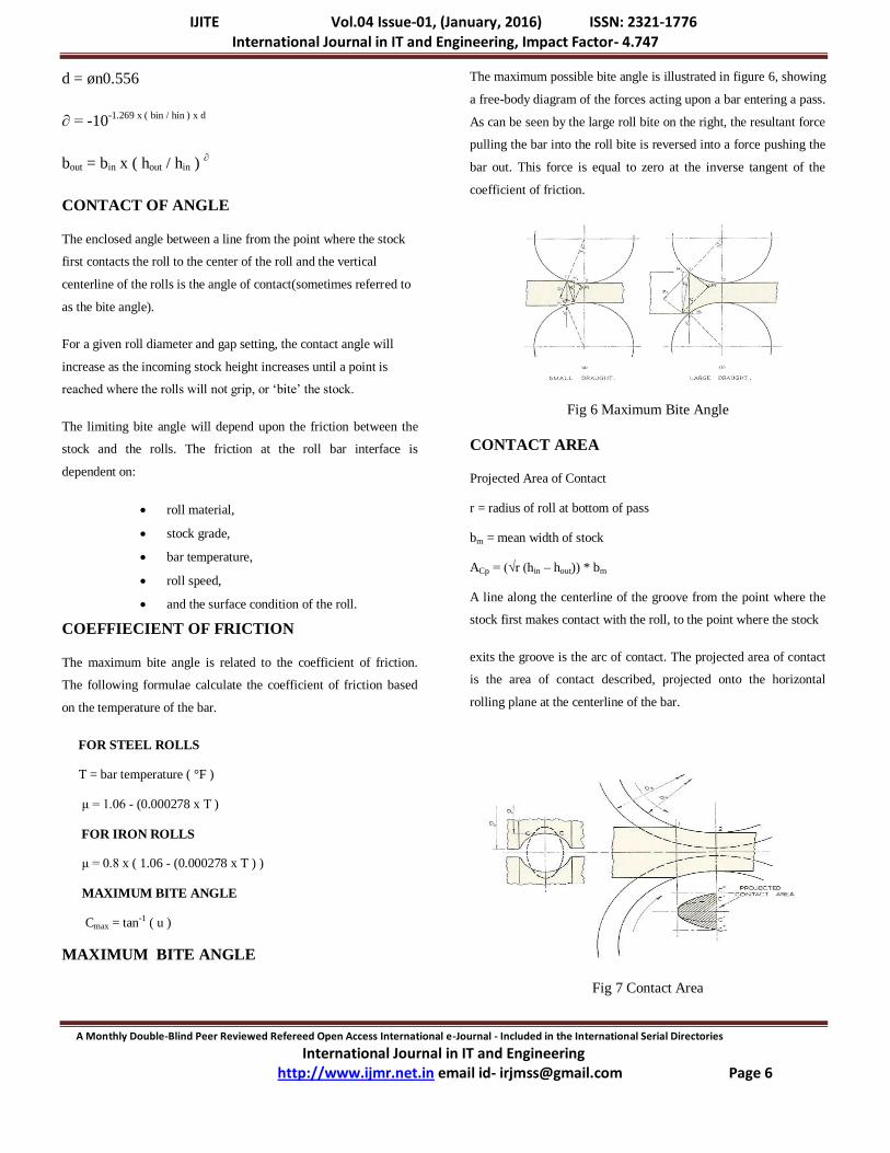
The maximum possible bite angle is illustrated in figure 6, showing
a free-body diagram of the forces acting upon a bar entering a pass.
As can be seen by the large roll bite on the right, the resultant force
pulling the bar into the roll bite is reversed into a force pushing the
bar out. This force is equal to zero at the inverse tangent of the
coefficient of friction.
Fig 6 Maximum Bite Angle
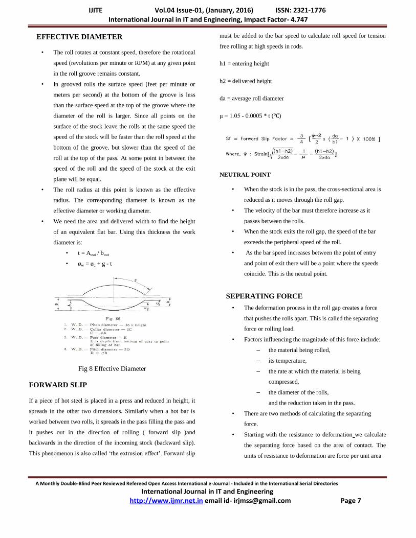
CONTACT AREA
Projected Area of Contact
r = radius of roll at bottom of pass
bm = mean width of stock
ACp = (√r (hin – hout)) * bm
A line along the centerline of the groove from the point where the
stock first makes contact with the roll, to the point where the stock
exits the groove is the arc of contact. The projected area of contact
is the area of contact described, projected onto the horizontal
rolling plane at the centerline of the bar.
Fig 7 Contact Area
IJITE Vol.04 Issue-01, (January, 2016) ISSN: 2321-1776 International Journal in IT and Engineering, Impact Factor- 4.747
A Monthly Double-Blind Peer Reviewed Refereed Open Access International e-Journal - Included in the International Serial Directories
International Journal in IT and Engineering http://www.ijmr.net.in email id- [email protected] Page 7
EFFECTIVE DIAMETER
• The roll rotates at constant speed, therefore the rotational
speed (revolutions per minute or RPM) at any given point
in the roll groove remains constant.
• In grooved rolls the surface speed (feet per minute or
meters per second) at the bottom of the groove is less
than the surface speed at the top of the groove where the
diameter of the roll is larger. Since all points on the
surface of the stock leave the rolls at the same speed the
speed of the stock will be faster than the roll speed at the
bottom of the groove, but slower than the speed of the
roll at the top of the pass. At some point in between the
speed of the roll and the speed of the stock at the exit
plane will be equal.
• The roll radius at this point is known as the effective
radius. The corresponding diameter is known as the
effective diameter or working diameter.
• We need the area and delivered width to find the height
of an equivalent flat bar. Using this thickness the work
diameter is:
• t = Aout / bout
• øw = øc + g - t
Fig 8 Effective Diameter
FORWARD SLIP
If a piece of hot steel is placed in a press and reduced in height, it
spreads in the other two dimensions. Similarly when a hot bar is
worked between two rolls, it spreads in the pass filling the pass and
it pushes out in the direction of rolling ( forward slip )and
backwards in the direction of the incoming stock (backward slip).
This phenomenon is also called „the extrusion effect‟. Forward slip
must be added to the bar speed to calculate roll speed for tension
free rolling at high speeds in rods.
h1 = entering height
h2 = delivered height
da = average roll diameter
μ = 1.05 - 0.0005 * t (℃)
NEUTRAL POINT
• When the stock is in the pass, the cross-sectional area is
reduced as it moves through the roll gap.
• The velocity of the bar must therefore increase as it
passes between the rolls.
• When the stock exits the roll gap, the speed of the bar
exceeds the peripheral speed of the roll.
• As the bar speed increases between the point of entry
and point of exit there will be a point where the speeds
coincide. This is the neutral point.
SEPERATING FORCE
• The deformation process in the roll gap creates a force
that pushes the rolls apart. This is called the separating
force or rolling load.
• Factors influencing the magnitude of this force include:
– the material being rolled,
– its temperature,
– the rate at which the material is being
compressed,
– the diameter of the rolls,
and the reduction taken in the pass.
• There are two methods of calculating the separating
force.
• Starting with the resistance to deformation we calculate
the separating force based on the area of contact. The
units of resistance to deformation are force per unit area

IJITE Vol.04 Issue-01, (January, 2016) ISSN: 2321-1776 International Journal in IT and Engineering, Impact Factor- 4.747
A Monthly Double-Blind Peer Reviewed Refereed Open Access International e-Journal - Included in the International Serial Directories
International Journal in IT and Engineering http://www.ijmr.net.in email id- [email protected] Page 8
Figure below illustrates this force applied to the rolls when rolling
flats.
Fig 9 Separating Force
• Starting with the motor power required, we calculate the
torque from the roll RPM, the separating force using the
moment arm from the centre of the contact area to find
the separating force.
TORQUE
• The torque is calculated by using the centroid of the
contact area as the point where the separating force is
applied.
• The distance from the roll centre to the centre of the
contact area is the moment arm.
– F = separating force
– d = moment arm
– Τ = F x d
– Power is work per unit time. Torque is
rotational work, rotation rate (RPM) is the rate
the work is applied. Starting at the motor, the
torque is found using the roll RPM.
Fig 10 Torque
RRPM = roll RPM
P = motor power
For metric units:
P = ( Tt * RRPM ) / 9.55
Tt = ( P * 9.55 ) / RRPM
RESULTS AND OBSERVATION
TABLE 1
Material: Alluminium
Length of the material: 100mm
Width of the material: 50 mm
Thickness of the material: 1mm
TABLE OF PERFORMANCE TESTS
No of passes
Gap Between the rollers(mm)
Change in Length of the material(mm)
Change in Width of the work/mm
Change in Thickness of the material /mm
Pass 1
Pass 2
Pass 3 Pass 4
Pass 5
Pass 6
1.25
1
0.75 0.5
0.25
0.25
100
109
122 145
226
332
50
50
50 51
52
52
1
1
1 0.8
0.6
0.4
STRAIN CALCULATION
S.NO ELONGATION STRAIN IN
WIDTH OF
THE
MATERIAL
STRAIN IN
THICKNESS
OF THE
MATERIAL
1 0 0 0
2 0.09 0 0
3 0.11 0 0
4 0.18 0.02 0.2
5 0.55 0.019 0.25
6 0.47 0 0.33
IJITE Vol.04 Issue-01, (January, 2016) ISSN: 2321-1776 International Journal in IT and Engineering, Impact Factor- 4.747
A Monthly Double-Blind Peer Reviewed Refereed Open Access International e-Journal - Included in the International Serial Directories
International Journal in IT and Engineering http://www.ijmr.net.in email id- [email protected] Page 9
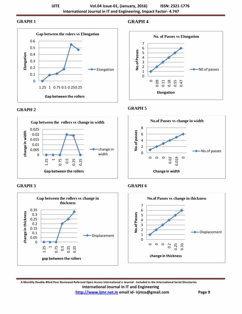
GRAPH 1
GRAPH 2
GRAPH 3
GRAPH 4
GRAPH 5
GRAPH 6
0
0.1
0.2
0.3
0.4
0.5
0.6
1.25 1 0.75 0.5 0.250.25
Elo
nga
tio
n
Gap between the rollers
Gap between the rolers vs Elongation
Elongation
0
0.005
0.01
0.015
0.02
0.025
1.25
1
0.75 0.
5
0.25
0.25
chan
ge in
wid
th
Gap between the rollers
Gap between the rollers vs change in width
change in width
00.05
0.10.15
0.20.25
0.30.35
1.2
5 1
0.7
5
0.5
0.2
5
0.2
5
cha
nge
in t
hic
kne
ss
gap between the rollers
Gap between the rollers vs change in
thickness
Displacement
01234567
0
0.09
0.11
0.18
0.55
0.47
No
.of P
asse
s
Elongation
No. of Passes vs Elongation
N0.of passes
0
2
4
6
8
0 0 0
0.0
2
0.01
9 0
No
.of p
asse
s
Change in width
No.of Passes vs change in width
No.of passes
01234567
0 0 0
0.2
0.25
0.33
No
.of P
asse
s
change in thickness
No.of Passes vs change in thickness
Displacement
IJITE Vol.04 Issue-01, (January, 2016) ISSN: 2321-1776 International Journal in IT and Engineering, Impact Factor- 4.747
A Monthly Double-Blind Peer Reviewed Refereed Open Access International e-Journal - Included in the International Serial Directories
International Journal in IT and Engineering http://www.ijmr.net.in email id- [email protected] Page 10
OBSERVATION
It is been observed from the above graphs that, length of the
material is increasing gradually with a slight difference in width
and thickness.
From pass 4 we can observe wavy edges. At pass 5 and pass 6 we
can observe that the edges are broken.
APPLICATIONS OF ALUMINUM SHEETS
Aluminium is also a popular metal used in sheet metal due to its
flexibility, wide range of options, cost effectiveness, and other
properties. The four most common aluminium grades available as
sheet metal are 1100-H14, 3003-H14, 5052-H32, and 6061-T6.
Grade 1100-H14 is commercially pure aluminium, highly chemical
and weather resistant. It is ductile enough for deep drawing and
weldable, but has low strength. It is commonly used in chemical
processing equipment, light reflectors, and jewellery.
Grade 3003-H14 is stronger than 1100, while maintaining the same
formability and low cost. It is corrosion resistant and weldable. It is
often used in stamping, spun and drawn parts, mail
boxes, cabinets, tanks, and fan blades.
Grade 5052-H32 is much stronger than 3003 while still maintaining
good formability. It maintains high corrosion resistance and
weldability. Common applications include electronic chassis, tanks,
and pressure vessels. Grade 6061-T6 is a common heat-treated
structural aluminium alloy. It is weldable, corrosion resistant, and
stronger than 5052, but not as formable. It loses some of its
strength when welded. It is used in modern aircraft structures.
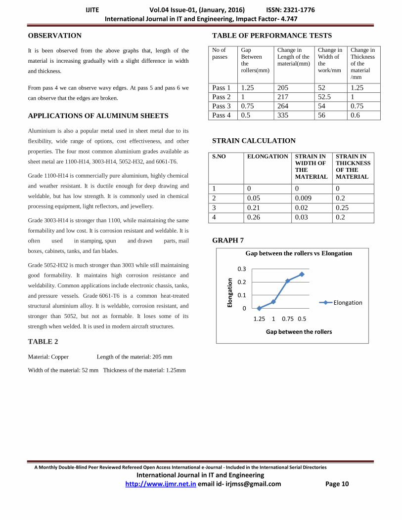
TABLE 2
Material: Copper Length of the material: 205 mm
Width of the material: 52 mm Thickness of the material: 1.25mm
TABLE OF PERFORMANCE TESTS
No of passes
Gap Between the rollers(mm)
Change in Length of the material(mm)
Change in Width of the work/mm
Change in Thickness of the material /mm
Pass 1 1.25 205 52 1.25
Pass 2 1 217 52.5 1
Pass 3 0.75 264 54 0.75
Pass 4 0.5 335 56 0.6
STRAIN CALCULATION
S.NO ELONGATION STRAIN IN
WIDTH OF
THE
MATERIAL
STRAIN IN
THICKNESS
OF THE
MATERIAL
1 0 0 0
2 0.05 0.009 0.2
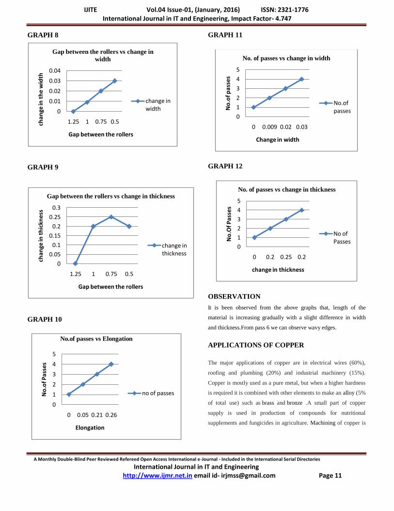
3 0.21 0.02 0.25
4 0.26 0.03 0.2
GRAPH 7
0
0.1
0.2
0.3
1.25 1 0.75 0.5
Elo
nga
tio
n
Gap between the rollers
Gap between the rollers vs Elongation
Elongation
IJITE Vol.04 Issue-01, (January, 2016) ISSN: 2321-1776 International Journal in IT and Engineering, Impact Factor- 4.747
A Monthly Double-Blind Peer Reviewed Refereed Open Access International e-Journal - Included in the International Serial Directories
International Journal in IT and Engineering http://www.ijmr.net.in email id- [email protected] Page 11
GRAPH 8
GRAPH 9
GRAPH 10
GRAPH 11
GRAPH 12
OBSERVATION
It is been observed from the above graphs that, length of the
material is increasing gradually with a slight difference in width
and thickness.From pass 6 we can observe wavy edges.
APPLICATIONS OF COPPER
The major applications of copper are in electrical wires (60%),
roofing and plumbing (20%) and industrial machinery (15%).
Copper is mostly used as a pure metal, but when a higher hardness
is required it is combined with other elements to make an alloy (5%
of total use) such as brass and bronze .A small part of copper
supply is used in production of compounds for nutritional
supplements and fungicides in agriculture. Machining of copper is
0
0.01
0.02
0.03
0.04
1.25 1 0.75 0.5chan
ge in
th
e w
idth
Gap between the rollers
Gap between the rollers vs change in
width
change in width
0
0.05
0.1
0.15
0.2
0.25
0.3
1.25 1 0.75 0.5
chan
ge in
th
ickn
ess
Gap between the rollers
Gap between the rollers vs change in thickness
change in thickness
0
1
2
3
4
5
0 0.05 0.21 0.26
No
.of P
asse
s
Elongation
No.of passes vs Elongation
no of passes
0
1
2
3
4
5
0 0.009 0.02 0.03
No
.of p
asse
s
Change in width
No. of passes vs change in width
No.of passes
0
1
2
3
4
5
0 0.2 0.25 0.2
No
.Of P
asse
s
change in thickness
No. of passes vs change in thickness
No of Passes
IJITE Vol.04 Issue-01, (January, 2016) ISSN: 2321-1776 International Journal in IT and Engineering, Impact Factor- 4.747
A Monthly Double-Blind Peer Reviewed Refereed Open Access International e-Journal - Included in the International Serial Directories
International Journal in IT and Engineering http://www.ijmr.net.in email id- [email protected] Page 12
possible, although it is usually necessary to use an alloy for
intricate parts to get good machinability characteristics.
RECENT TECHNOLOGIES
Heated Roll Rolling, and the suitability of this technique
for magnesium sheet production.
Asymmetric Cryorolling, which has potential for large-
scale industrial production of nanostructural materials
Variable-Gauge Rolling, used for production of flat
products with variable thicknesses
Through-width Vibration Rolling, used for fabrication of
ultrafine material sheets.
CONCLUSION
Flat rolling is a forming method which reduces the cross-
sectional area of the work piece, i.e. a semi-finished
product and enlarges its length. Furthermore, material
properties such as strength, toughness and surface
structure are enhanced.
It is been observed from the graphs that, as the gap
between the rollers decreases we can observe that length
of the material is increasing gradually with a slight
difference in width and thickness.
As the No. of passes increases we can observe that length
of the material is increasing gradually with a slight
difference in width and thicknes
REFERENCES
Manufacturing Engineer‟s reference book by
D KOSHAL Butterworth –Heinemann
Hot Rolling of steel William L. Roberts
Flat Rolling Fundamentals Vladimir B. Ginzburg, Robert
Ballas
Rolling Bearing Analysis,Tedric A. Harris.
Ginzburg, V.B. (1993). High quality steel rolling, theory
and practice, Chap. 9. Marcel-Dekker, New York,.