kinematic stability of roller pairs in free-rolling contact
TRANSCRIPT

NASA TECHNICAL NOTE
KINEMATIC STABILITY OF ROLLER PAIRS IN FREE-ROLLING CONTACT
Michuel Suvuge und Stuart H. Loewenthul I/
1 ' "
? rLewis Research Center 1 . I
NASA JJN ,D-8146 &
?.:TSi;f.J C O P Y : RETURN TO 2.F-VJL TECHNICAL LIBRARY
KIRTLAND AFB, M. M.
/ .
N A T I O N A L AERONAUTICS A N D SPACE A D M I N I S T R A T I O N W A S H I N G T O N , D. C. FEBRUARY 1976

--
TECH LIBRARY KAFB,NM
IIllillllHl11111IllUIll1llllllllllllllIIII .. -~ ~~
1. Report No. 2. Government Accession No.
NASA TN D-8146 4. Title and Subtitle
KINEMATIC STABILITY OF ROLLER PAIRS IN FREE -ROLLING CONTACT
7. Authods)
9. Performing organization Name and Address
NASA Lewis Research Center and U. S. Army Air Mobility R & D Laboratory Cleveland, Ohio 44135
12. Sponsoring Agency Name and Address
National Aeronautics and Space Administration Washington, D. C. 20546
16. Abstract
0333824
i 5. Report Date February 1976
6. Performing Organization Code
I 8. Performing Organization Report No.
10. Work Unit No.
505-04 11. Contract or Grant No.
13. Type of Report and Period Covered
Technical Note 14. Sponsoring Agency Code
A se t of generalized stability equations is developed for ro l le r pa i r s in free-rol l ing contact. A symmetr ic , dual-contact model was used. Four possible external contact profiles that possess continuous contacting sur faces were studied. It was found that kinematic stability would be insured i f the la rger radius of t ransverse curvature , in absolute value, and the smal ler rolling radius both exist on the ro l le r that has the apex of i t s conical sur face outboard of i t s main body. The stability c r i t e r i a developed are considered to be useful for assessing axial res t ra in t requirements for a variety of ro l le r mechanisms and in the selection of ro l le r contact geometry for traction dr ive devices.
17. Key Words (Suggested by Author(s)1 18. Oistribution Statement
Rollers; Roller kinematics; Roller dynamics; Unclassified - unlimited Dynamic stability; Roller mechanism; STAR category 37 ( r ev . ) Rotating bodies; Conical bodies; Kinematics; Stability
- .
19. Security Classif. (of this report1 20. Security Classif. (of this page)
Unclassified Unclassified
KINEMATIC STAB I L l l Y OF ROLLER PAIRS IN FREE-ROLLING CONTACT
by Michael Savage* and Stuart H. Loewenthal
Lewis Research Center and U. S. A r m y A i r Mobility R&D Laboratory
SUMMARY
A set of generalized stability equations is developed for roller pairs in free-rolling contact. A symmetric, dual-contact model was used. Four possible external contact profiles that possess continuous contacting surfaces were studied. These consisted of convex-convex, convex-straight, convex-concave, and straight-straight geometries. It was found that kinematic stability is insured if the larger radius of transverse curvature, in absolute value, and the smaller rolling radius coexist on the roller that has the apex of its conical surface outboard of its main body. If roller instability does develop, in the form of roller skewing, relative axial motion will occur in the direction of the roller end with the smaller rolling radius.
The stability criteria developed are considered to be useful for assessing axial restraint requirements for a variety of roller mechanisms and in the selection of roller contact geometry for traction drive devices.
INTRODUC TION
It is not well recognized that elastic cylindrical bodies that have been placed in rolling contact wil l produce axial motions no matter how carefully these elements have been manufactured or alined. Consideration of component axial motion and the control of attendant thrust forces has had a strong influence on the design of several mechanical devices. The most notable examples a re the design of railroad wheel-rail sets for lateral stability (refs. 1 to 3), the cambering of flat belt pulleys for self-centering action (ref. 4), the axial feed action of centerless grinding machines (ref. 5), the thrust capability of cylindrical roller bearings (ref. 6) and the axial stability of rollers in traction drives devices (ref. 7).
*Assistant Professor of Mechanical Engineering, Case Western Reserve University, Cleveland, Ohio; Summer Faculty Fellow at the Lewis Research Center in 1974.

The railroad wheel-rail contact typifies the contact that is common to many roller mechanisms in that the wheel and rail represent a pair of roller elements with the rail being a roller of infinite radius. The one major difference in the analysis and design of these contacts is that, in the case of the railroad wheel contact, the wheel sets must carry a significant mass (the railroad car) and must accelerate it in the axial direction as the train rounds a curve. Thus, in this case, the wheel-rail contact must be capable of reacting a large axial force. For this reason the wheels have a significant flange which is used to provide the required axial force from its contact with the rail. Since it is desirable that the wheels run true on the rails with little flange contact when the train is running straight, axial stability considerations become an important factor in their design.
The primary cause of axial motion of the wheel set is skewing. The flanges, which provide a kinetic support for the wheel set, are always on the inside of the wheels. This produces a wheel cone with its apex outside the wheel set. The effect of these cones is to provide a kinematic stabilization of the wheel set as it runs on the rails. Were the cones reversed, the wheel sets would oscillate wildly in an axial mode as the train moves down the track (ref. 1).
Two basic causes of roller axial motion a re identified in this study. These are skewing and externally applied axial thrust. Both causes can be converted into correcting mechanisms that will enable the rollers to roll true (i.e . , in their plane of contact without axial motion). The first correcting mechanism is kinematic; the second is kinetic. Although a kinetic o r force correction, in the form of a roller flange o r bumper, is sometimes required to insure that gross axial motion cannot occur, the kinematic correction is unquestionably more desirable. The kinematic correction, which results in self-centering action, can be implemented without seriously affecting either the mechanical efficiency o r durability of the contact. Axial motion that is not corrected kinematically will create significantly large thrust forces that have to be withheld by flanges or thrust bearings. The investigation conducted by Virabov (ref. 7) shows that even a minute misalinement between the contact and spin axes of interacting cylindrical rollers caused by unavoidable e r rors in the manufacture o r alinement of the rolling bodies will result in significant axial forces being generated. Tests results for a pair of 50millimeter (2-in. ) diameter steel rollers running dry (traction coefficient = 0.32) indicated that a roller skew angle of only 0.27' will produce a thrust force that is 24 percent of the normal load acting on the body. Obviously, roller flanges o r thrust bearings that a re required to operate continuously under such conditions would be unattractive from a system life and performance standpoint.
In a private communication to the authors, Dr. Veljko Milenkovic extended his work regarding the stability of a railroad wheel-rail contact (ref. 1)to the more generalized case of roller pairs in free-rolling contact. In this communication, he advocated the technique of using self-corrective geometries to promote roller stability. Milenkovic's
2

work gave incentive to the present investigation. The objective of the study reported herein was to establish a specific stability cri
terion for external roller pairs in free-rolling contact. Roller contact profiles that comply with this criterion will promote a self-correcting action of the roller pair that has been disturbed from parallelism.
C
R
r *
rl V
IVC/P
vP X,Y, Z
a
AU
P
0
SYMBOLS
center distance of transverse curvature (eq. (15)), cm (in.)
radial distance from spin axis of cylinder to the center of transverse curvature, cm (in.)
rolling radius, cm (in.)
nominal rolling radius of cylinder in plane 1at z = 0 (figs. 5 and 7), cm (in.)
tangential velocity, cm/sec (in. /sec)
velocity of cylinder a's center relative to pitch line, cm/sec (in./sec)
central tangential pitch line velocity, cm/sec (in./sec)
Cartesian coordinate system
inclination of contact normal from radial direction (figs. 4 to 6 and 7), deg
slip velocity, cm/sec (in. /sec)
radius of transverse curvature, cm (in. )
angular velocity of cylinder, rad/sec
Subscripts:
a cylinder a
b cylinder b
1 plane 1
2 plane 2
Superscripts:
a axial direction
t tagent ia l direction
3

KINEMATIC MODEL
Axial Motion
The contact of interest is that of two cylindrical elements rolling on each other. This can be modeled in one plane as a pair of rolling circles o r in a continuous series of parallel planes as a sequence of rolling circles rigidly attached to each other along the respective axes of the two cylinders. A kinematic analysis of the effects of misalinement require that at least two planes of contact be considered, such as the two planar model shown in figure 1.
In the model slight variations in rolling radii from the nominal radii ra and rb are considered. However, each cylinder is a rigid body, thus the planar rolling circles at each end of the cylinder must move as a single unit. In plane 1the pitch point velocity of cylinder b is given by
while in plane 2, it is
'2b = r2bWb
For cylinder a these two velocities would be
'la = rlaua
and
For no slip at plane 2
'2a = '2b
r2aua = r2bWb
o r
'2b a =-93
r ~ a
(3)
(4)
4
I

-
---
--
_.. .. .......... . .
In plane 1from equations (3) and (7),
- r2b "b
'la r2a
For no slippage also at plane 1
vlb =
and, from equations (l),(8), and (9),
lb - r2b wb r2 a
or
As shown in figure 2(a), if rlb/rla is greater than r2b/r2a and pwe rolling exists at
the contact in plane 2, then slippage will occur at the contact in plane 1. For the geometry shown, where r2a = r2b and rla < rlb, a slip velocity wil l be developed in the positive x direction between the contacting points on the roller surfaces. Thus,
AUl = Vlb - Vla
will be a positive slip velocity of roller b under roller a. Friction wil l convert this relative velocity into a tractive force that tends to skew cylinder a on cylinder b as shown in figure 2(b). This skewing wil l generate a component of the relative velocity of cylinder a's center with respect to the pitch point in the axial direction from plane 2 to plane 1. This velocity component is in the direction towards the smaller rolling radius circle. The tangential component of this relative velocity Vt c /P
is subtracted from the pitch line velocity V for the net circumferential motion. The axial component of this relative velocity Va c /P
remains unopposed. This produces a net axial motion of cylinder a with respect to cylinder b as indicated in figure 2(b) by the relative velocity vectors. Unopposed, this axial motion o r v'walking", which is a consequence of roller skewing, will continue until either a mechanical restraint is encountered or the rollers have become disengaged.
5

Stability Criterion
Kinematic stability is achieved when a roller pair, which is momentarily disturbed from its equilibrium position by an external force, is capable of returning to a neutral position only because of corrective geometry changes. If the geometry of the contact between the two cylinders is such that the inequality that initiates this axial motion is changed to the equality of equation (11)by the axial motion, then the contacts will be kinematically stable. Therefore, to achieve kinematic stability, the object is to select the roller geometry that tends to satisfy equation (11) after the roller has been disturbed.
The model chosen to evaluate the roller's tendency to return to equilibirium assumes the contacting surfaces at the roller ends to be both continuous and symmetric. Since these surfaces are rigidly connected, axial motion of one roller relative to the other wi l i cause equal but opposite changes of contacting radius ratio at the roller ends. Therefore, the total stability question of the roller pair can be studied by considering the contact geometry changes at one end only. In plane 1 a stabilizing condition exists when
where z denotes a shift of cylinder a to the right as indicated in figure 2. Since the contact geometry is symmetric, then in plane 2
The sign of the inequality appearing in equation (13) is a consequence of the roliers tendency to move axially in the direction towards the end that possesses the smaller rolling radius. For the example selected in figure 2(a), as roller a moves in the positive z direction relative to roller b, the radius ratio rlb/rla is required to decrease in value in order to restore equilibrium in accordance with equation (11). Considering the antisymmetric behavior of the contact occurring in plane 2, just the opposite change would be required; that is, r2b/r2a is required to increase in value to restore equality between the radius ratios at each end. These stability requirements are reflected by equations (13)and (14)as'shown.
As previously mentioned, for roller bodies with symmetric ends, it is sufficient to consider the stability characteristics of the contacting geometry at only one end. In the analysis that follows, the contact occurring at the plane 1 end or ihe end on the right side of the roller wil l be examined.
The compliance of an axially disturbed roller pair to the criterion described in equation (13)will cause the rollers to eventually approach a condition of pure rolling where
6
I I

equation (11)is satisfied. If the axes are still skewed at this point, further motion will cause r2b/r2ato become larger than rlb/rla, which will tend to skew the axes in the opposite direction. This correction would tend to return the cylinders to their stable equilibrium point of pure rolling where these ratios are equal. In practice, a damped oscillation would most likely result. A roller pair exhibiting this behavior would be considered to have both axial a s well as angular kinematic stability.
Basic Assumptions
The following analysis is based on several assumptions: (1)The axes of the rolling cylinders remain sufficiently parallel to enable the con
tact to be treated as though it occurred in one plane. Thus, skewing motion and its resultant axial motion are both small. Neither motion significantly affects the transverse rolling geometry model of this analysis.
(2) The skewing of one roller on another is primarily a second-order rolling phenomenon that can be modeled by considering two planes of rolling contact. The differential action between these two planes is treated a s the basic cause of roller skewing.
(3) The roller ends are symmetric so that antisymmetric behavior occurs in the two contact planes as the rollers shift axially.
The contacting surfaces can now be classified by their transverse curvatures as long as single-point contact is maintained between the two rollers at each end. The combinations that assure this are (as shown in fig. 3) (I) convex-convex, (11)convex-straight, (III)convex-concave, and (N)straight-straight. In the analysis to follow, the contact occurring at the right end of the rollers will be the plane 1contact.
KINEMATIC STABILITY
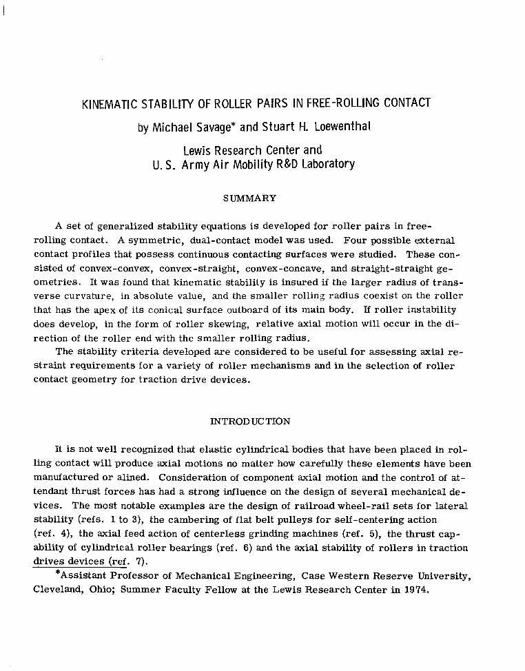
In the case of two convex surfaces, the axial motion will be such as to maintain the distance between the centers of transverse curvature, considering the geometric effect of skewing to be negligible. In the analysis to follow, p is the transverse radius of curvature, r is the rolling radius, and R is the radial distance from the roller's spin axis to the center of transverse curvature. If p cos a! is less than r, R is positive. The angle CY is the inclination of the contact normal from the radial direction. It is also the angle that describes the contact slope relative to the axial direction. In each of the cases examined, roller b will be the roller that has the apex of its conical surfaces outboard of its main body for positive a in plane 1.
Figure 4 shows two cylinders in contact, both of which have transverse convex surfaces. The a cylinder is shown in two adjacent positions to clarify the effect of the ax
7

--
ial motion dz on the contact geometry. In this case the effect is to increase a! by the angle da. I� C is defined as the center distance of transverse curvature, then
C = P a + &
and the slope angle a! is related to z by
and
The contact radii are given by
and
Thus
For stability
zsins!=-C
dc2 - 2 cos a! = " L
rla = Ra + pa cos a!
rlb = Rb + pb cos a!
- Rb 4 'Os a!
ria R, + pa COS a!
After some differentiation and the appropriate algebra,
The sign of this expression is controlled by (rlbpa - rlab) tan a!, which will indicate kinematic stability according to equation (13) when it is negative. For a positive a! (asdrawn in fig. 4) stability occurs when
8

. .. .. ....... .__.I___..___-- ..- I ...... ,,.
or
For positive a, the b roller will have the apex of i ts conical contact surface outboard of the roller ends as shown in figure 4. Since the transverse curvature of roller a is shown to be significantly smaller than that of roller b, kinematic stability can be ,
expected even though the rolling radii of both bodies are nearly the same. However, if the radii of transverse curvature happen to be nearly equal, the rolling radius of the b roller must be smaller than that of the mating roller a for definite kinematic stability. For the double convex contact, it can be stated that the kinematic stability is defined by the sign of equation (21).
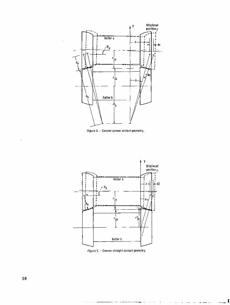
Figure 5 shows two rollers in contact: one has convex transverse curvature, and the other has a straight transverse profile. In this case C is infinite, so a slight modification is required in the previous analysis. Equation (19) still holds but the rolling radius of the straight coned roller becomes
* rib = rlb - (z - pa sin a!) tan a!
* where rlb is the nominal rolling radius of that roller at the plane in which z has a zero value. The ratio of rolling radii in plane 1becomes
* 'lb - 'lb - (z - pa sin a)tan CY
~- - ~
r la Ra + pacas a,
Note that in this case, the angle a,, the inclination of the contact, is constant with changes in z since the shape of the straight cone does not change along i ts surface. For stability in accordance with equation (13), differentiation of equation (25) yields
where stability is insured for this set of contacts as long as the angle a! is positive as drawn. Thus, the cone shaped roller must be the one with the apex outboard of its main body. In this case the radii of transverse curvature dictate stability, since one is infinite and the other is finite. This can be appreciated by setting 4 equal to infinity in equation (23).
9

The third case of roller combinations is shown in figure 6. Here roller a has cqvex transverse curvature along its contact surfaces, and roller b has concave transverse curvature. This condition makes negative and greater than pa in absolute value, so C from equation (15) is also negative. This also makes z negative for the geometry as shown but equation (21) is still applicable with the use of a negative radius of transverse curvature 43 for the concave surface. The sign is again de
2termined by (rlbpa - rla&) (tan a)/Crla where C is no longer positive definite. Since C is negative and a is positive for the geometry as drawn, stability is
defined by
or
Since pa is positive and 40 is negative by definition of the transverse curvature, the drawn geometry is stable for positive cy. A reversed cone slope, that is, negative a, would make this contact unstable. The railroad wheel-rail contact is in agreement with this criterion.
The last contact pair to be considered is that of two straight sided cylinders. Figure 7 illustrates this* condition. As in the second case, assign the nominal rolling* radii the symbols rla and rlb. The angle a is the cone half angle o r the inclination of the cone surface to the axes and z denotes the axial travel of cylinder a relative to b to the right. Unlike the previous cases no kinematically defined point of rolling contact exists to identify plane 1. Assume that this plane is located at the midpoint of the* * contact of the spool model. Thus rla and rlb become the radii at the contact center and
* zrla = rla - -tan a 2
* zrlb = rlb - -tan a 2
Note that both rolling radii decrease with relative axial travel z. Thus, the radius ratio becomes
* z - 2 t a n a
10

and
(rib - r )-tan a la 2
2r la
which is quite similar to equation (21). As before, the sign is controlled by (rib - ria) tan a! since r2 is always positive.la
As drawn, the angle a is positive and stability is defined by
Thus, a stable contact of straight sided cylinders would have the larger radius cylinder taper inward. Equal radii cylinders would be neutrally stable and thus have no restoring properties. Neutral stability exists for straight cylinders with no taper regardless of the value of the rolling radii. This is a direct consequence of tan a = 0, so that
for the taperless cylinders.
DISCUSSION
The analysis presented indicates that three basic parameters affect the kinematic stability of free-rolling conical roller pairs :
(1)half contact cone slope a!
(2) rolling radius rb/ra (3) transverse curvature ratio &/pa
The implications of the stability criteria for the cases examined are summarized in table I for positive and negative a. For rollers of equal rolling radii, the larger radius of transverse curvature must be on the roller whose half cones have apexes outside the roller as shown on roller b in each analysis. This is a factor in case I, and the dominant factor in cases II and III. It does not come into play in case IV because both rollers have the same radius of transverse curvature - infinity. A second factor is that the smaller of the two rolling radii must be on the half cone with an external apex. This interacts with the first consideration in case I, is not a factor in cases 11and III, and is the dominant stability factor in case IV. In all cases, if the larger radius of transverse curvature, in absolute value, and smaller rolling radius both exist on the roller that has the apex of its conical surface outboard of i ts main body, the stability of the contact is
11

insured. This is the situation fo r the railroad wheel-rail contact. Secondly, for all cases an equality in eqtuation (13) indicates a neutrally stable
geometry that does not by itself cause skewing or axial motion. However, as in the case of straight rollers, since no corrective action is present, instabilities may occur.
Finally, it can be stated that the stability criteria presented is only the start in indicating how roller pairs should be modified to inhibit skewing o r axial motion. The contact geometry of internal and external rolling cylinders and those clustered together should also be studied. A quantitative relation can be sought between the corrective action of these geometries and external thrust forces o r torques applied to the rollers. Extreme deviations from a straight cylindrical contact geometry in consideration of stability will most likely have an adverse effect on roller contact performance and durability due to an increase in the contact's sliding velocity. Thus, the selection of an optimum roller profile for a given application is usually a balanced compromise among several factors. The merit function should include minimum size, maximum efficiency, maximum durability, and maximum stability.
SUMMARYOF RESULTS
A set of generalized stability equations for conically shaped roller pairs in free-rolling contact have been developed. A symmetric, dual-contact model was used. Four possible contact profiles that possess continuous contacting surfaces were studied. The profiles examined were convex-convex, convex-straight, convex-concave, and straight-straight. The following results were obtained:
1. Axial and angular kinematic stability of a roller pair can be insured if the larger radius of transverse curvature, in absolute value, and the smaller rolling radius both exist on the roller that has the apex of its conical surface outboard of its main-body. The stability of roller pairs that do not conform to this geometric relationship must be assessed on a case by case basis in accordance with their transverse profiles and the stability criteria developed herein.
2. A result of roller kinematic instability is roller skewing. Skewing precipitates relative axial motion in the direction towards the roller end with the smaller rolling radius. The roller stability criteria presented can be used in assessing the axial restraint requirements for a variety of roller mechanisms and in particular, the selection
12

of roller contact geometry for traction drive devices where roller spatial stability is of major design importance.
Lewis Research Center, National Aeronautics and Space Administration,
Cleveland, Ohio, October 20, 1975 975-05.
REFERENCES
1. Milenkovic, V. : The Generalized Problem of Laterial Guidance Stability in Wheeled Vehicles. ASME Paper 70-Tran-17, Oct. 1970.
2. Wickens, A. H. : The Dynamics of Railway Vehicles on Straight Track: Fundamental Considerations of Lateral Stability. Proc. Inst. Mech. Eng., vol. 180, pt. 3F, 1965-1966, pp. 29-44.
3. Evensen, D. A. ; and Kaplan, A. : Some Problems of Wheel/Rail Interaction Associated with High-speed Trains. Bull. Int. Railway Congr. Assoc., Sept. 1969, pp. 513-542.
4. Swift, H. W.: Cambers for Belt Pulleys. Proc. Inst. Mech. Eng., vol. 122, June 1932, pp. 627-671.
5. Woodburg, Robert S. : History of the Grinding Machine. Massachusetts Inst. Tech. Press, 1959.
6. Korrenn, H. : The Axial Load-Carrying Capacity of Radial Cylindrical Roller Bearing. J. Lub. Tech., vol. 92, no. 1, Jan. 1970, pp. 129-137.
7. Virabov, R. V. : Znfluence of Shaft Misalignment on Friction-Drive Tractive Properties. Russian Eng. J., vol. 53, no. 7, 1973, pp. 20-24.
13

TABLE I. - SUMMARY OF GEOMETRIC RELATIONSHIPS
FOR THE KINEMATIC STABILITY OF FREE-ROLLING,
DUAL-CONTACT CONICAL ROLLERS
Case
I
11
111
1V
Contact geometry Stability cri teria
apositive cy Negative a
Convex-convex
Convex-straight (43 = a)
Convex -concave ( 'Pb l >Pa '
Straight-straight
'b ,, 43- ..ra Pa Stable
Stable
r .-. rba
-> - pb'b
ra Pa Unstable
Unstable
r < rb a
aPositive cy when roller main body. Negative a cone apex.
Plane 2
b has cone apex outboard of when roller b has inboard
A i r c l e al
'-'Ib
FiOllr@1. - Two-plane rolling model.
14

Y
t
(a) Differential slip velocity.
t "b t x
- 2
0)Skewing arid axial velocity generation.
Figure 2 - Roller kinematic instability.
(a) I. Convex-convex. 0)11. Convex-straight.
(c) 111. Convex-concave. (d) IV. Straight-straight.
Figure 3. - Roller contact geometries.
15
Displacedt ' oosition,7
Figure 5. - Convex-straight contact geometry.
16
. . . . . . , , . . . . . .. .. ,., ...., ,, ..-.-I

I
DisplacedIposition
I
. J
-a-
U Figure 6. - Convex-concave contact geometry.
a
plane
Figure 7. - Straight-straight contact geometry.
NASA-Langley, 1976 E-8419 17

NATIONAL AERONAUTICS AND SPACE ADMINISTRATION WASHINGTON. D.C. 20546
POSTAGE A N D FEES P A I D._ N A T I O N A L AERONAUTICS A N D
OFFlC I AL BUSI NESS SPACE A D M I N I S T R A T I O N PENALTY FOR PRIVATE USE w o o SPECIAL FOURTH-CLASS RATE 451
BOOK
240 001 C 1 U D 760123 50090305 D E P T O f THE A I R FLlRCE AF W t A P O N S L A R O P . A T O R Y A T T N : T E C H N I C A L L I B R A R Y SUL) K I K T L A N D A F R RIM 87117
If Uiidrlivernble (Section 158POSTMASTER : Postall A l a r i r i n l ) Do Not Return
“The aeronautical anL space uctivities of the United States shall be conducted so us to contribute . . . to the expansion of buman knowledge of phenomena in the atmosphere and sflace. T h e Administration shall provide for the widest practicable and appropriate disseminutiolz of information concerning its activities and the results thereof.”
-NATIONAL AERONAUTICSAND SPACEACT OF 1958 ’
NASA SCIENTIFIC AND TECHNICAL PUBLICATIONS TECHNICAL REPORTS: Scientific and technical information considered important, complete, and a lasting contribution to existing knowledge.u
TECHNICAL NOTES: Information less broad in scope but nevertheless of importance as a contribution to existing knowledge.
TECHNICAL MEMORANDUMS: Information receiving limited distribution because of preliminary data, security classification, or other reasons. Also includes conference proceedings with either limited or unlimited distribution. -CONTRACTOR REPORTS: Scientific and technical information generated under a NASA contract or grant and considered an important contribution to existing knowledge.
Details on the availability of these
TECHNICAL TRANSLATIONS: Information published in a foreign language cpnsidered to merit NASA distribution in Engi’ish:
PUBLICAT1oNS: Information derived from or of value to NASA activities. Publications include final reports of major projects, monographs, data compilations, handbooks, sourcebooks, and special bibliographies.
TECHNOLOGY UTILIZATION I
PUBLICATIONS: Information on technology used by NASA that may be of particular interest in commercial and other-non-aerospace applications. Publications include Tech Briefs, Technology Utilization Reports and Technology Surveys.
publications may be obtained from:
. SCIENTIFIC AND TECHNICAL INFORMATION OFFICE
N A T I O N A L A E R O N A U T I C S A N D SPACE A D M I N I S T R A T I O N Washington, D.C. 20546