series 1750 – 1753 and 1758 general purpose incubatorsphm.utoronto.ca/~ddubins/man/hotpack.pdf ·...
TRANSCRIPT

SERIES 1750 – 1753 and 1758
GENERAL PURPOSE INCUBATORS and
HUMIDITY CHAMBERS 33 CU. FT. CAPACITY
OPERATION / MAINTENANCE MANUAL
MODEL # ______________________ SERIAL # ______________________
935 Mearns Road Warminster, PA 18974 (800) 523-2327 001 (215) 672-7800 Internet: www.hotpack.com For Service, contact:
SP TechCare Phone: (877) 548-4666
001 (215) 672-7800 FAX: (877) 693-9273
001 (215) 672-1702 E-mail: [email protected]
Part Number: MAN251 Revision: C, 3-9-05

Hotpack 1750 – 1753 and 1758 Series Incubators / Humidity Chambers
Copyright © 2005, SP Industries.
All rights reserved.
WARNING: DO NOT STORE OR PROCESS FLAMMABLE MATERIALS This unit is not designed nor is it intended to be used for the purpose of processing or storage of materials that may contain volatile flammable solvents or that may emit flammable vapors during processing or storage.

i
IMPORTANT SYMBOLS USED IN THIS MANUAL
Within this manual, please read closely any warnings, instructions, and advice accompanied by the following symbols:
WARNING
INSTRUCTION
ADVICE
INJURY OR EVEN DEATH MAY RESULT IF A RECOMMENDATION MARKED
WITH THIS SYMBOL IS NOT HEEDED.
This symbol also indicates equipment safety compo-nents and safety features.
IMPORTANT INSTRUCTIONS
To prevent damage to chamber equipment and/or load, adhere to procedures marked by this icon.
PRACTICAL TIPS
These recommendations are intended to streamline control operation and prevent common operator errors.
ii
TABLE OF CONTENTS
FOREWORD ................................................................................. IV Inspection........................................................................................................... iv Warranty Information ........................................................................................ iv Service................................................................................................................ iv
1) INTRODUCTION / SPECIFICATIONS..........................................1
2) INSTALLATION...........................................................................3 Location and Placement...................................................................................... 3 Electrical Connection.......................................................................................... 3 Water Supply (Humidity-equipped units only).................................................. 5
3) COMPONENTS ...........................................................................7 Models 317502 & 317582 (Heat only) .............................................................. 7 Models 317512 & 317583 (Heat + Refrigeration)............................................. 8 Models 317522 & 417522 (Heat + Humidity)................................................... 9 Models 317532, 417532, & 417533 (Heat + Refrig. + Humidity) .................. 10 Rear View (Typical, Upper Rear Grille Removed) ......................................... 11 Top View (Typical, Canopy Removed)........................................................... 12 Inside Ceiling View (Typical, Panel Removed) ............................................... 12 Recorder Option................................................................................................ 13 Dryer Option ..................................................................................................... 13
4) OPERATION (93-SERIES CONTROLLER)..................................14 Start-Up............................................................................................................. 14 The Controller Interface.................................................................................... 14 Changing the Set Point Value ........................................................................... 17 Unlocking and Locking the Controller ............................................................. 17
Unlocking...................................................................................................... 18 Locking ......................................................................................................... 18
Setting the Deviation Alarm Band.................................................................... 19 Changing the Low Limit............................................................................... 19 Changing the High Limit .............................................................................. 19
Setting a Calibration Offset Value.................................................................... 20 Changing from Centigrade to Fahrenheit ......................................................... 21 Restoring Factory Default Parameter Settings.................................................. 21 Quick Reference: Hotpack / Watlow Series 93 Controller.............................. 22
5) MAINTENANCE ........................................................................24
6) TROUBLESHOOTING ...............................................................28 Deviation Alarms .............................................................................................. 28 Troubleshooting Table ...................................................................................... 28 Controller Error Code Messages....................................................................... 31

iii
APPENDICES
Appendix A: Operation & Setup Menus.......................................................... 34 Appendix B: Controller Default Settings (Typical)......................................... 35 Appendix C: Electrical Schematics & Parts Lists............................................ 37 Appendix D: Temperature / Humidity Data (Dryer-Equipped Units) ............. 48 Appendix E: Service Safety Assurance Form.................................................. 49

iv
FOREWORD
Inspection Before leaving our factory, each unit is certified by Hotpack’s Quality Assurance Department and carefully packed. Inspect all containers upon arrival for visible loss or damage, and report any damage on the carrier’s freight bill or express receipt. Failure to do so may void the carrier’s responsibility. Should concealed loss or shipping damage be observed after opening containers, have the carrier inspect the packaging within 15 days of delivery, and then file a claim with the carrier. Hotpack ships units with drop-recorder devices affixed (usually to the upper rear panel area). Read the device according to the directions labeled on the shipping container. If a recorder indicates that the unit has been dropped during shipment (typically a blue arrow in the direction of the drop), notify the carrier immediately. Hotpack will assist in claims, but must be notified immediately and sent a copy of the carrier’s inspection report.
Warranty Information The Hotpack Warranty card must be returned within ten (10) days after the unit has been placed in operation. If a problem or question regarding unit operation arises, please note it on the warranty card or contact SP TechCare via the telephone number listed below.
Service For service, or to order replacement parts, contact SP TechCare: Phone: 877) 548-4666. By Fax: (877) 693-9273. Hotpack products are engineered to provide many years of satisfactory service. Should a Hotpack product require servicing, trained service personnel are available from Hotpack’s Nationwide Service Network. When ordering replacement parts, please supply the unit’s model and serial number, plus all electrical information on the nameplate. Part numbers are listed in the Appendix section of this manual.

_____________________________________________________________________________ Hotpack Series 1750 – 1753 , 1758 Incubators & Humidity Chambers
1
INTRODUCTION / SPECIFICATIONS
Hotpack’s line of general purpose floor-model incubators and humidity chambers is designed to provide accurate, precise, and reliable control of temperature and humidity conditions. Their microprocessor-based P. I. D. controllers regulate heating, refrig-eration, and humidification systems as indicated in Table 1-1, “Specifications,” on the following page. Long-lasting nickel chromium heating elements are standard and efficient mechanical air convection maximizes chamber unifor-mity. An over-temperature safety limit thermostat prevents equipment or product load damage in the event of a malfunction. All interiors, shelves, shelf supports, and air ductwork are manu-factured of stainless steel. All exterior panels (excluding the control console and exterior door shell) are stainless steel. On humidity-equipped units, achievable humidity is a function of the controlled temperature, as indicated in the following chart:
On dryer-equipped units, achievable humidity is described in the Appendix section of this manual on page 48. Optional system components include:
• Two-pen circular chart recorder (°C, % R.H.). • Auxiliary dehumidification dryer. • Programmable ramp /soak microprocessor controller. • DI water cartridge system to maximize water quality. • High temperature decontamination cycle.
317532417532417533
317522417522
317532 417532 417533
+

_____________________________________________________________________________ Hotpack Series 1750 – 1753 , 1758 Incubators & Humidity Chambers
2
Table 1-1. Specifications.
MODEL 317502 3175821
317512 317583 1
317522 417522
317532 417532 417533
FEATURES 2 TT TT ++ RR TT ++ HH TT ++ RR ++ HH
TEMPERATURE RANGE
(& UNIFORMITY @ 2°C, 37°C, AND
50°C)
35 – 60°C ± 0.15°C @ 37°C ± 0.60°C @ 50°C
0 – 60°C
± 0.35°C @ 2°C ± 0.15°C @ 37°C± 0.60°C @ 50°C
35 – 70°C
± 0.15°C @ 37°C ± 0.60°C @ 50°C
0 – 70°C
± 0.35°C @ 2°C ± 0.15°C @ 37°C ± 0.60°C @ 50°C
–10 to 70°C
± 0.35°C @ 2°C ± 0.15°C @ 37°C± 0.60°C @ 50°C
HUMIDITY RANGE @ 25°C - - - - - - - - 20 to 98% RH
(± 2% control)
AMBIENT TEMPERATURE
These units are designed to operate to specification up to a maximum ambient temperature of 90°F (32°C).
CHAMBER VOLUME 33 cu. ft. (934 liters)
CHAMBER DIMENSIONS
(USABLE W x D x H)
36 x 27 x 60 in. 91 x 69 x 152 cm
NOTE: For 317582 and 317583, height is 62.5 in. (159 cm)
EXTERIOR DIMENSIONS
(W x D x H)
41 x 35 x 90 in. 104 x 89 x 229 cm
NOTE: For 317582 and 317583, height is 85.5 in. (217 cm)
SHELVES
Supplied: 4 Maximum: 19 Area (each): 6 sq. ft. ( 0.5 sq. meter)
NOTE: For 317582 and 317583, roller apparatus and shelves are optional.
ELECTRICAL SERVICE 3
1.1 kW, 115 V 60 Hz, 10 A
2.1 kW, 230 V 60 Hz, 9.5 A
2.0 kW, 115 V 60 Hz, 16 A
3.0 kW, 230 V 60 Hz, 13 A
3.0 kW, 230 V 60 Hz, 14 A
SHIPPING WEIGHT 1200 lbs., 544 kg 1400 lbs., 636 kg 1200 lbs., 544 kg 1600 lbs., 727 kg 1600 lbs., 727 kg
1 Identical to above model except door is designed to allow smooth entry of wheeled carts, etc.
2 T = Heating R = Refrigeration H = Humidification
3 Main Supply voltage should not exceed ±10% of normal voltage. Listed amperage is for base unit without options. Consult serial label on unit for your unit’s exact current draw. Plug-in units are Installation Category II. Units requiring hard-wired “terminal block” power connection are Category III.

_____________________________________________________________________________ Hotpack Series 1750 – 1753 , 1758 Incubators & Humidity Chambers
3
INSTALLATION
Location and Placement LIFTING AND TRANSPORTING — Lift and move the unit with a power or manual machine fork machine only. Do not attempt to lift the unit by hand. Avoid damaging the unit’s underside when inserting forks. AMBIENT CONDITIONS — Choose a site free from rapidly changing ambient temperature conditions (due to summer heat or window sun exposure, for example). On units without refrig-eration, the lowest achievable chamber temperature is a function of ambient temperature. VENTILATION — To assure proper ventilation, allow a mini-mum of 2 inches (5 cm) clearance between adjacent walls and the rear and side of the unit. If two units or more are positioned side by side, allow a minimum of 4 inches (10 cm) between cabinets. LEVELING — The unit should be leveled from both side-to-side and front-to-back by adjusting the unit’s adjustable leveling legs. No leg adjustment is available on units equipped with casters. OPTIONAL DRYER:
MG-90 Rotary-Bed Desiccant Dryer: Connect dryer hoses “A” and “B” to their correspondingly labeled ports on the rear of the unit. The other two dryer ports are for bed reactivation. The reactivation output port may be externally vented as required. See dryer manual.
P/N 222353 Compressed-Air-Powered Dryer: Refer to Addendum #048 for air-source requirements, air connection information, and other dryer information.
Electrical Connection
CAUTION Be sure that the power supply is the same voltage as specified on the nameplate.

_____________________________________________________________________________ Hotpack Series 1750 – 1753 , 1758 Incubators & Humidity Chambers
4
On units supplied with a power cable and three-prong (grounding) plug, the user should have the wall receptacle and circuit checked by a qualified electrician to ensure that the receptacle is properly grounded. It is the user’s responsibility to replace a two-prong (ungrounded) receptacle with a properly grounded three-prong wall receptacle. Ensure that the total current demand on the circuit to be used (including current demand from other apparatus) does not exceed the circuit’s capacity. Table 2-1. Electrical Requirements.
MODEL VOLTAGE SERVICE RATING
317522, 417522 115 Volt 20 Amp
317532, 417532, 417533 208 / 230 Volt 20 Amp
317502, 317582 115 Volt 15 Amp
317512, 317583 208 / 230 Volt 15 Amp
WARNINGS
• For personal safety, this unit must be properly grounded.
• On units supplied with a power cable and plug, set the power switch to the OFF position before plugging the power cord into the electrical outlet. Do not, under any circumstances, cut or remove the third prong (ground) from the power cord. Do not use a two-prong adapter plug.
• On units requiring a customer-supplied power con-nection, use only copper conductors, making all connec-tions in accordance with applicable schematics and local, state, and national electrical code regulations. During such installation, disconnect the electrical power supply and place a tag at the disconnect switch indicating that you are working on the circuit.

_____________________________________________________________________________ Hotpack Series 1750 – 1753 , 1758 Incubators & Humidity Chambers
5
Water Supply (Humidity-equipped units only) Chamber humidification equipment must be supplied with a reliable source of clean, demineralized, filtered, single-distilled or single deionized water. Water quality is the primary cause of premature humidifier failure, causing heater element failure by encrustation (with minerals from hard water) or corrosion (by DI water with excessive resistivity). Inadequate water quality can also damage the unit’s piping, chamber, and door. System malfunctions caused by poor water quality are excluded from warranty coverage. Water resistance must be within the range of 50 KΩ-cm to 1 MΩ-cm. Water silica level must be < 10 ppm. Hotpack does not recommend use of ultra-pure water (such as triple distilled, triple deionized, or high purity reverse osmosis water) because these increase the potential for stainless steel corrosion. Water pH should be > 6.5. Since the water quality used on this unit is beyond the manufac-turer’s control, Hotpack cannot assume responsibility for water-related damage or repairs to the humidification system or chamber (excluding defective materials or workmanship).1 WATER CONNECTION — Water for the vapor generator feeds the water reservoir float box located on the top of the unit (see page 12 for reservoir location). Remove the unit’s rear upper panel and pour approximately 500 ml (8 ounces) of water into the bottom of the water reservoir to create a seal in the drain line trap. Use 1/4" O.D. semi-rigid plastic tubing (Weatherhead P/N 24004 or equivalent) to connect the water supply line to the fitting at the rear top of the water reservoir.2 WATER PRESSURE — At least 25 PSI water pressure is recommended. Pressure should not exceed 60 PSI. Gravity feed systems may not be adequate. If you have any questions on the adequacy of the water supply line, contact SP TechCare. Reservoir water level is adjustable by rotating a screw located on the top of the reservoir’s float. Keep the reservoir’s water level 1-1/4" (3 cm) from the top of the tank to ensure submersion of the
1 On humidified units equipped with a Hotpack water demineralizing system, this disclaimer is waived and the humidification system components and work chamber are warranted for 12 months.
2 To remove the tubing from the fitting later, pull the tubing while pressing the fitting’s round collar.

_____________________________________________________________________________ Hotpack Series 1750 – 1753 , 1758 Incubators & Humidity Chambers
6
immersion heater and to prevent activation of the water level safety switch. If the water level is too low, the vapor generator safety limit may be activated, preventing higher humidity levels from being generated. Low water levels or an inconsistent water supply may damage the vapor generator. DRAIN — Models 317522, 317532, 417522, 417532, and 417533 are equipped with a condensate trough located in the base of the chamber. Connect the trough’s drain port to a suitable drain.

_____________________________________________________________________________ Hotpack Series 1750 – 1753 , 1758 Incubators & Humidity Chambers
7
COMPONENTS
Models 317502 & 317582 (Heat only) POWER SWITCH — This two-position rocker switch controls main power to the unit. TEMPERATURE CONTROLLER — This microprocessor-based controller allows the user to input values for temperature set point and tempera-ture deviation alarm. In normal operation, the upper LED readout displays actual chamber temperature while the lower LED readout dis-plays the temperature set point. INTAKE / EXHAUST CONTROL— When in the OPEN (Out) position, this vent control allows mixing of ambient air and chamber air. In the CLOSED (In) position, chamber air is isolated from ambient air.

_____________________________________________________________________________ Hotpack Series 1750 – 1753 , 1758 Incubators & Humidity Chambers
8
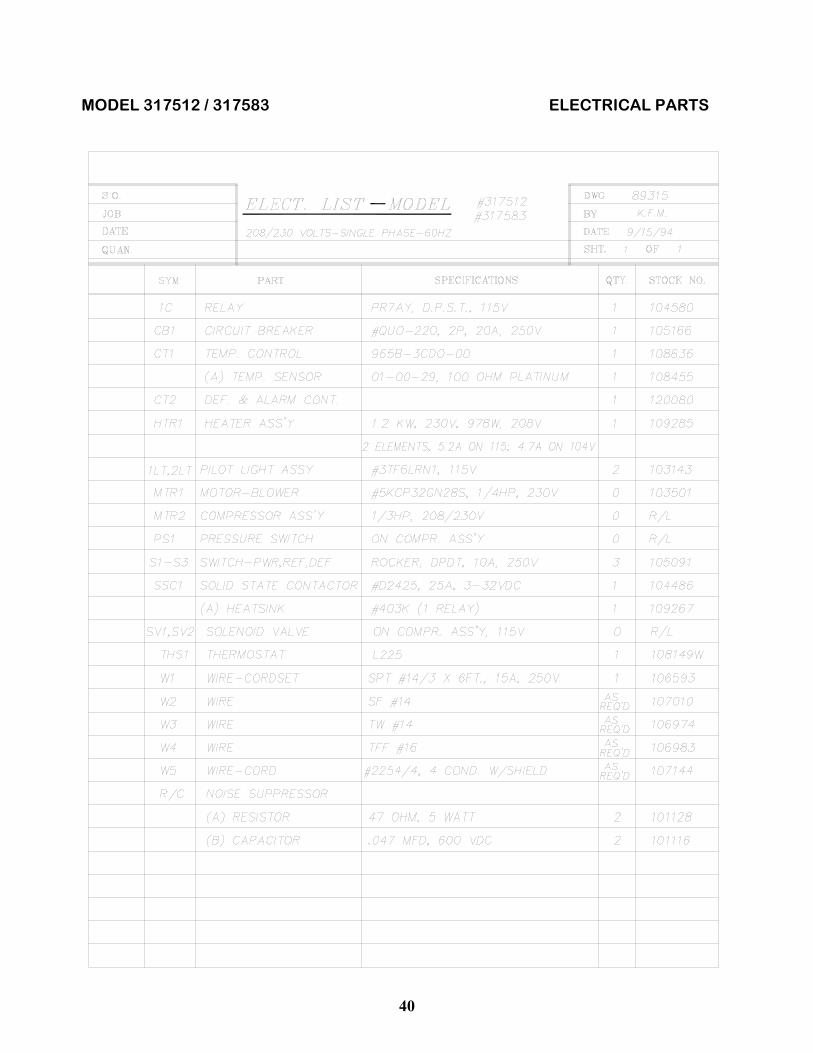
Models 317512 & 317583 (Heat + Refrigeration) POWER SWITCH — This two-position rocker switch controls main power to the unit. TEMPERATURE CONTROLLER — This microprocessor-based controller allows the user to input values for temperature set point and tempera-ture deviation alarm. In normal operation, the upper LED readout displays actual chamber temperature while the lower LED readout dis-plays the temperature set point. DEFROST SWITCH — This two-position switch activates the unit’s automatic defrost cycle timer circuit. When the unit is controlling to tem-peratures below 10°C (50°F), the defrost switch must be ON. The factory setting for this circuit is for two 8-minute defrost cycles per day. Settings are available for four cycles per day and 16-minute defrost cycles (see the electrical schematic). REFRIGERATION SWITCH — This two-position switch energizes the unit’s refrigeration system. It should be ON whenever the temperature set point is near or below the potential ambient temperature. INTAKE / EXHAUST CONTROL — When in the OPEN (Out) position, this vent control allows mixing of ambient air and chamber air. In the CLOSED (In) position, chamber air is isolated from ambient air.

_____________________________________________________________________________ Hotpack Series 1750 – 1753 , 1758 Incubators & Humidity Chambers
9
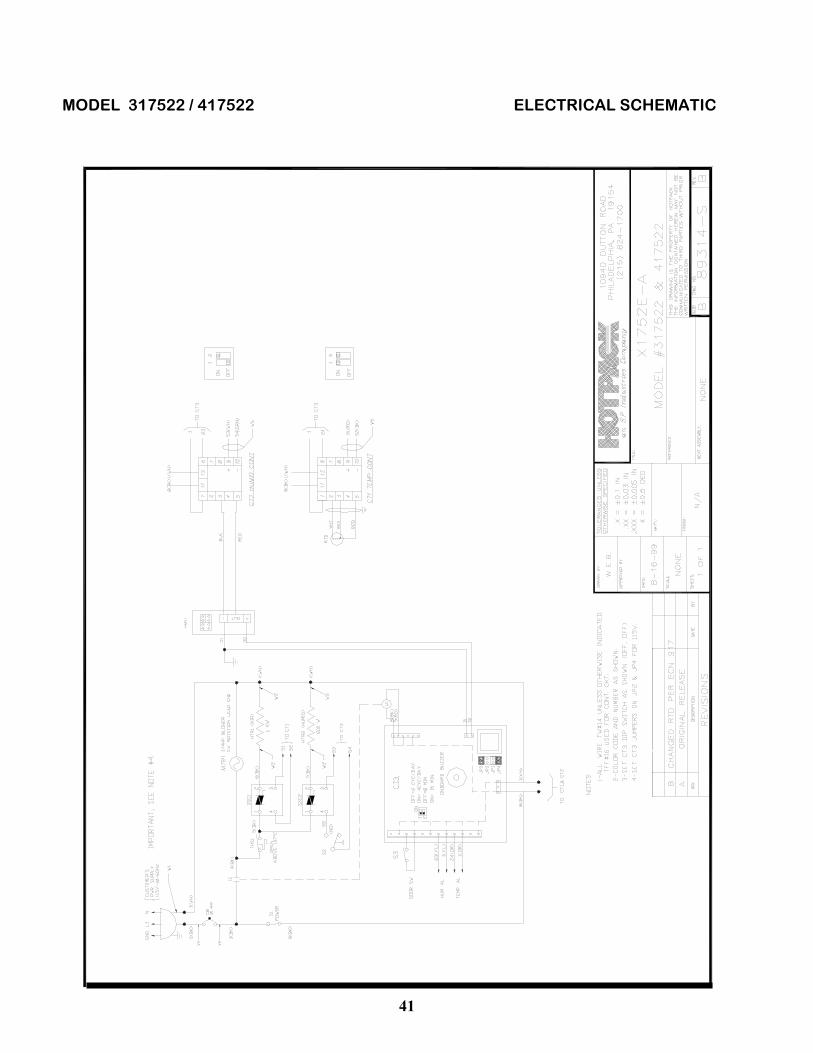
Models 317522 & 417522 (Heat + Humidity) POWER SWITCH — This two-position rocker switch controls main power to the unit. TEMPERATURE CONTROLLER — This microprocessor-based controller allows the user to input values for temperature set point and tempera-ture deviation alarm. In normal operation, the upper LED readout displays actual chamber temperature while the lower LED readout dis-plays the temperature set point. HUMIDITY CONTROLLER — This microprocessor-based controller allows the user to input values for humidity set point and humidity deviation alarm. In normal opera-tion, the upper LED readout displays actual chamber humidity while the lower LED displays the humidity set point. INTAKE / EXHAUST CONTROL — When in the OPEN (Out) position, this vent control allows mixing of ambient air and chamber air. In the CLOSED (In) position, chamber air is isolated from ambient air.

_____________________________________________________________________________ Hotpack Series 1750 – 1753 , 1758 Incubators & Humidity Chambers
10
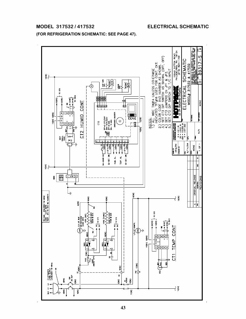
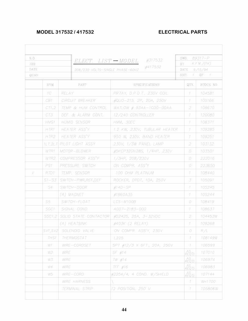
Models 317532, 417532, & 417533 (Heat + Refrig. + Humidity) POWER SWITCH — This two-position rocker switch controls main power to the unit. TEMPERATURE CONTROLLER — This microprocessor-based con-troller allows the user to input values for temperature set point and tem-perature deviation alarm. In normal operation, the upper LED readout displays actual chamber temperature while the lower LED readout dis-plays the temperature set point. HUMIDITY CONTROLLER — This microprocessor-based controller allows user input of values for humi-dity set point and humidity deviation alarm. In normal operation, the upper LED readout displays actual chamber humidity while the lower LED displays the humidity set point. DEFROST SWITCH — This two-position switch activates the unit’s automatic defrost cycle timer circuit. When the unit is controlling to tem-peratures below 10°C (50°F), the defrost switch must be ON. The factory setting for this circuit is for two 8-minute defrost cycles per day. Settings are available for four cycles per day and 16-minute defrost cycles (see the electrical schematic). REFRIGERATION SWITCH — This two-position switch energizes the unit’s refrigeration system. It should be ON whenever the temperature set point is near or below the potential ambient temperature.
INTAKE / EXHAUST CONTROL — When in the OPEN (Out) position, this vent control allows mixing of ambient air and chamber air. In the CLOSED (In) position, chamber air is isolated from ambient air.

_____________________________________________________________________________ Hotpack Series 1750 – 1753 , 1758 Incubators & Humidity Chambers
11
Rear View (Typical, Upper Rear Grille Removed)
Label (Humidified Units Only):
CAUTION Failure to maintain proper deionized water quality and pressure can DAMAGE this equipment and VOID the manufacturer’s warranty. To prevent damage to this equipment, connect only de-ionized water that meets these specifications:
• 25 – 60 PSI pressure. • pH: > 6.5 • Resistivity: 50k to 1 meg-ohm. • Silica Level: < 10 ppm.
Refer to the Operation / Maintenance manual for additional water quality and maintenance information.

_____________________________________________________________________________ Hotpack Series 1750 – 1753 , 1758 Incubators & Humidity Chambers
12
Top View (Typical, Canopy Removed)
Inside Ceiling View (Typical, Panel Removed)
1
1 Refrigeration-equipped models only. 2 Humidity-equipped models only. Typical position shown.
2
VAPOR GENERATOR ASSY (HUMIDIFIED UNITS ONLY)
_____________________________________________________________________________ Hotpack Series 1750 – 1753 , 1758 Incubators & Humidity Chambers
13
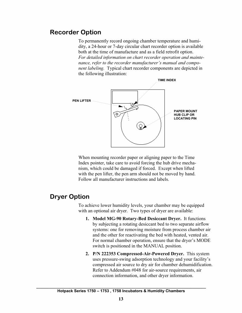
Recorder Option To permanently record ongoing chamber temperature and humi-dity, a 24-hour or 7-day circular chart recorder option is available both at the time of manufacture and as a field retrofit option. For detailed information on chart recorder operation and mainte-nance, refer to the recorder manufacturer’s manual and compo-nent labeling. Typical chart recorder components are depicted in the following illustration:
When mounting recorder paper or aligning paper to the Time Index pointer, take care to avoid forcing the hub drive mecha- nism, which could be damaged if forced. Except when lifted with the pen lifter, the pen arm should not be moved by hand. Follow all manufacturer instructions and labels.
Dryer Option To achieve lower humidity levels, your chamber may be equipped with an optional air dryer. Two types of dryer are available:
1. Model MG-90 Rotary-Bed Desiccant Dryer. It functions by subjecting a rotating desiccant bed to two separate airflow systems: one for removing moisture from process chamber air and the other for reactivating the bed with heated, vented air. For normal chamber operation, ensure that the dryer’s MODE switch is positioned in the MANUAL position.
2. P/N 222353 Compressed-Air-Powered Dryer. This system uses pressure-swing adsorption technology and your facility’s compressed air source to dry air for chamber dehumidification. Refer to Addendum #048 for air-source requirements, air connection information, and other dryer information.
TIME INDEX
PEN LIFTER
PAPER MOUNT HUB CLIP OR LOCATING PIN

_____________________________________________________________________________ Hotpack Series 1750 – 1753 , 1758 Incubators & Humidity Chambers
14
OPERATION (93-SERIES CONTROLLER)
Start-Up Press the control panel’s POWER switch to the ON position. Select settings for other panel switches and controls to suit the desired application as discussed for your model on pages 7 – 10. On humidity-equipped units, ensure the vaporizer’s water supply has been turned on. On MG-90 dryer-equipped units, ensure that the dryer’s MODE switch is in the MANUAL position. If an audible controller alarm occurs at start-up, the alarm can be silenced by pressing the INFINITY key once.
The Controller Interface The Watlow 93-Series microprocessor-based controller provides standard temperature and humidity control. This chapter describes the following controller operations:
1) Adjusting control temperature or humidity set point.
2) Locking and unlocking the software.
3) Setting the deviation alarm for temperature & humidity.
4) Setting the calibration offset for temperature & humidity.
5) Changing temperature display from Celsius to Fahrenheit.
The 93-Series Temperature / Humidity controller comprises the following controls and displays pictured in Figure 4-1 on the following page. The identical controller is used for both Temperature and Humidity. Figure 4-1 depicts a typical Default Display seen during normal operation (Upper Display = actual value; Lower Display = set point).
CAUTION The Watlow 93-Series controller permits modification of a large array of Setup and Operation parameters. To avoid making inadvertent parameter changes that could adversely affect unit operation, Hotpack recommends maintaining factory default settings for all menu parameters, especially configura-tion locking (LOC=3).
_____________________________________________________________________________ Hotpack Series 1750 – 1753 , 1758 Incubators & Humidity Chambers
15
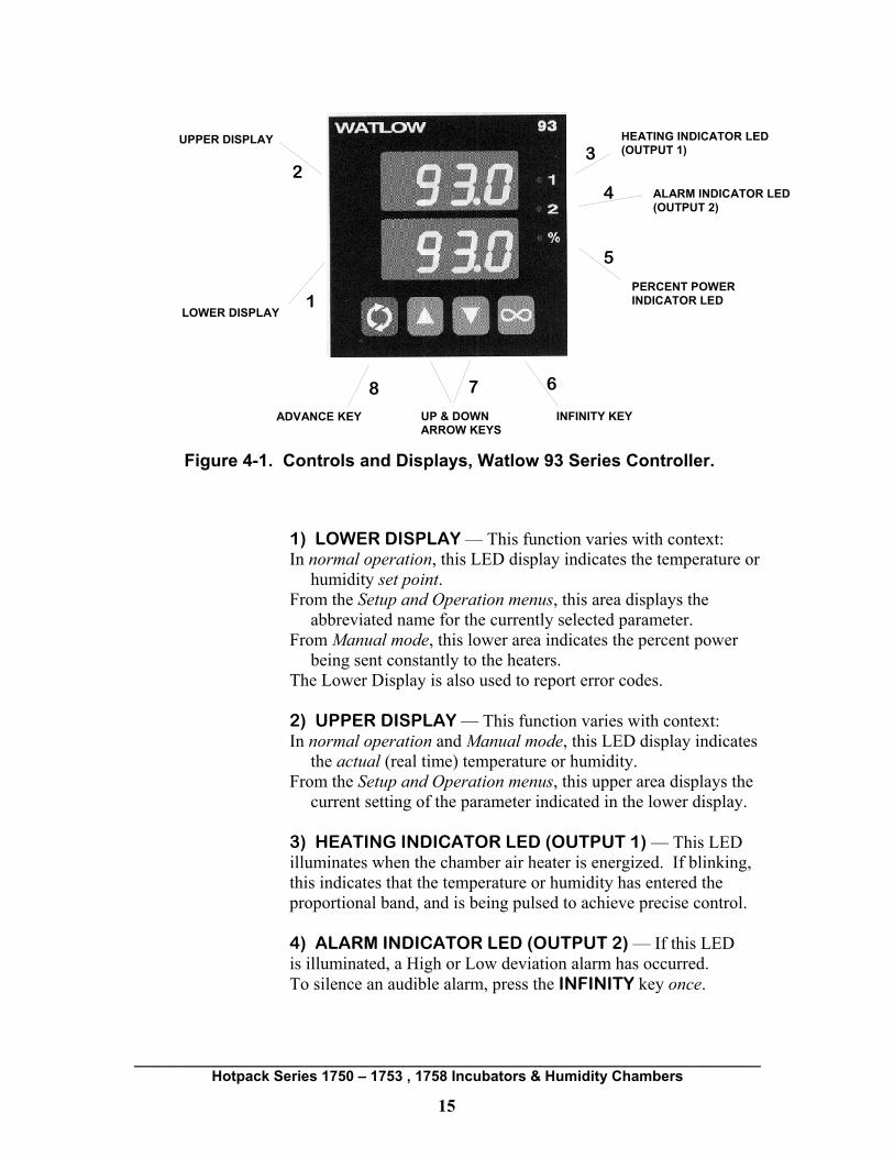
Figure 4-1. Controls and Displays, Watlow 93 Series Controller.
1) LOWER DISPLAY — This function varies with context: In normal operation, this LED display indicates the temperature or
humidity set point. From the Setup and Operation menus, this area displays the
abbreviated name for the currently selected parameter. From Manual mode, this lower area indicates the percent power
being sent constantly to the heaters. The Lower Display is also used to report error codes. 2) UPPER DISPLAY — This function varies with context: In normal operation and Manual mode, this LED display indicates
the actual (real time) temperature or humidity. From the Setup and Operation menus, this upper area displays the
current setting of the parameter indicated in the lower display. 3) HEATING INDICATOR LED (OUTPUT 1) — This LED illuminates when the chamber air heater is energized. If blinking, this indicates that the temperature or humidity has entered the proportional band, and is being pulsed to achieve precise control. 4) ALARM INDICATOR LED (OUTPUT 2) — If this LED is illuminated, a High or Low deviation alarm has occurred. To silence an audible alarm, press the INFINITY key once.
UPPER DISPLAY HEATING INDICATOR LED (OUTPUT 1)
ALARM INDICATOR LED (OUTPUT 2)
INFINITY KEY UP & DOWN ARROW KEYS
ADVANCE KEY
LOWER DISPLAY
PERCENT POWERINDICATOR LED 1
2 3
4
5
6 7 8

_____________________________________________________________________________ Hotpack Series 1750 – 1753 , 1758 Incubators & Humidity Chambers
16
5) PERCENT POWER INDICATOR LED — For normal operation this LED must be OFF, indicating that the unit is in Automatic (closed-loop) mode, controlling automatically to the set point. If this LED is ON, the unit is in Manual (open-loop) mode, applying constant heater power at the Percent Power level indi-cated in the Lower Display. In Manual mode the operator must attentively control Percent Power via the Up / Down arrow keys. To toggle between Automatic mode and Manual mode, press the Infinity key two times within 5 seconds while unlocked (LOC < 3). 6) INFINITY KEY — This key has two potential functions: A) Silencing Alarms, and B) Toggling between Automatic and Manual control modes. Under Hotpack default settings:
A) Press the Infinity key once to silence an audible alarm. By Hotpack factory defaults programming, deviation alarms are non-latching—that is, they self-silence without operator intervention when the chamber temperature subsequently re-enters the acceptable range. For more about deviation alarms see page 19.
B) Manual mode is inaccessible (LOC=3 under Setup). If the LOC parameter in the Setup menu has been changed from its factory default value of 3 to 0, 1, or 2, pressing the Infinity key twice within 5 seconds selects Manual mode. Repeating this two-press action returns the unit to Auto-matic mode. Used to supply a constant percent power to the heaters, Manual mode is a special function not ordi-narily recommended by Hotpack. See page 22, Note 2.
7) UP & DOWN ARROW KEYS — Vary with context: In normal operation, the arrow keys adjust the set point value
displayed in the Lower Display area. From within the Setup and Operation menus, the arrow keys select
from the range of available settings for the current parameter that is indicated in the Lower Display.
From Manual mode, the arrow keys adjust the percent power applied constantly to the heater element. Current percent power is displayed in the Lower Display area.
Pressing both the UP AND DOWN ARROW KEYS simulta-neously for 3 seconds displays the SETUP MENU followed by (for unlocked controllers only) the OPERATION MENU.

_____________________________________________________________________________ Hotpack Series 1750 – 1753 , 1758 Incubators & Humidity Chambers
17
8) ADVANCE KEY — This function varies with context: In normal operation with LOC=3 (locked) in Setup, the Advance
key is disabled. In the unlocked state (LOC = 0–2), the Advance key may be used at any time to access, scroll through, and make changes within the Operation menu.
From within the Setup and Operation menus, the Advance key is used to select menu parameters. The currently selected menu parameter appears in the Lower Display. If LOC=3, all menu parameters are displayed “read only.”
Hotpack strongly recommends maintaining LOC=3 in Setup.
Changing the Set Point Value To change the Temperature or Humidity set point during normal operation, press the UP OR DOWN ARROW KEY until the desired set point value appears in the Lower Display. Changes are self-entering after 5 seconds. NOTE: Changing the set point to a value that places the current actual chamber temperature outside the new deviation alarm band may activate an audible temperature deviation alarm. You can silence any alarm by pressing the Infinity key once.
Unlocking and Locking the Controller To change factory-set Operation menu parameters, the controller’s software security protection must first be unlocked. After desired changes have been made, Hotpack strongly advises re-locking the controller to protect against accidental changes.
CAUTION Changes to configuration locking (LOC) or other menu default settings can produce unexpected operational effects. Changes should be executed only by authorized personnel familiar with controller operation. Re-lock the controller after making changes. If unsure, contact Hotpack Service for assistance before making changes.
CAUTION Changing factory-set parameters is not recommended because incorrect settings could result in unexpected operation, alarms, or operational failure. Warranty coverage does not encompass chamber malfunction due to controller configuration errors.

_____________________________________________________________________________ Hotpack Series 1750 – 1753 , 1758 Incubators & Humidity Chambers
18
UNLOCKING
To unlock the controller:
1. Simultaneously press and hold the UP AND DOWN ARROW KEYS until LOC appears in the Lower Display, then release the keys. The Upper Display’s number indicates LOC status, with “3” representing the locked state. Any value less than 3 indicates an unlocked state.
2. Press the DOWN ARROW KEY until the Upper Display’s numerical value is 0. From this point, repeatedly pressing the ADVANCE key scrolls the displays first through the Setup menu, then the Operation menu. Changes may now be made to any parameters in these menus.
3. In the unlocked state, the ADVANCE key may be used at any time to access the Operation menu.
LOCKING
After changing parameter settings, protect them and prevent unintentional entry into Manual mode by locking the controller as follows:
1. If not already in the Setup menu, start from the Default Display (Upper Display = actual value; Lower Display = set point). If necessary, return to this display by repeatedly pressing the ADVANCE key.
2. Press and hold the UP AND DOWN ARROW KEYS simultaneously until LOC appears in the Lower Display, then release the keys. The Upper Display’s number indicates LOC status.
3. Press the UP or DOWN arrow key until LOC=3, which is the locked state. In the locked state, the ADVANCE key is inactive (except from the Setup menu) and both the Operation menu and Manual mode are inaccessible.
4. Press the ADVANCE key until the actual and set point conditions reappear on the displays.
_____________________________________________________________________________ Hotpack Series 1750 – 1753 , 1758 Incubators & Humidity Chambers
19
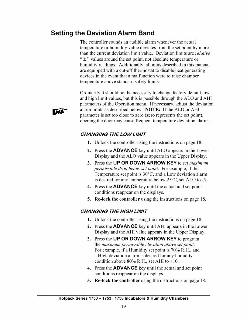
Setting the Deviation Alarm Band The controller sounds an audible alarm whenever the actual temperature or humidity value deviates from the set point by more than the current deviation limit value. Deviation limits are relative “ ± ” values around the set point, not absolute temperature or humidity readings. Additionally, all units described in this manual are equipped with a cut-off thermostat to disable heat generating devices in the event that a malfunction were to raise chamber temperature above standard safety limits. Ordinarily it should not be necessary to change factory default low and high limit values, but this is possible through the ALO and AHI parameters of the Operation menu. If necessary, adjust the deviation alarm limits as described below. NOTE: If the ALO or AHI parameter is set too close to zero (zero represents the set point), opening the door may cause frequent temperature deviation alarms.
CHANGING THE LOW LIMIT
1. Unlock the controller using the instructions on page 18.
2. Press the ADVANCE key until ALO appears in the Lower Display and the ALO value appears in the Upper Display.
3. Press the UP OR DOWN ARROW KEY to set maximum permissible drop below set point. For example, if the Temperature set point is 30°C, and a Low deviation alarm is desired for any temperature below 25°C, set ALO to -5.
4. Press the ADVANCE key until the actual and set point conditions reappear on the displays.
5. Re-lock the controller using the instructions on page 18. CHANGING THE HIGH LIMIT
1. Unlock the controller using the instructions on page 18. 2. Press the ADVANCE key until AHI appears in the Lower
Display and the AHI value appears in the Upper Display. 3. Press the UP OR DOWN ARROW KEY to program
the maximum permissible elevation above set point. For example, if a Humidity set point is 70% R.H., and a High deviation alarm is desired for any humidity condition above 80% R.H., set AHI to +10.
4. Press the ADVANCE key until the actual and set point conditions reappear on the displays.
5. Re-lock the controller using the instructions on page 18.

_____________________________________________________________________________ Hotpack Series 1750 – 1753 , 1758 Incubators & Humidity Chambers
20
Setting a Calibration Offset Value All Hotpack equipment is factory-calibrated with N.I.S.T-traceable instrumentation. However, it may at some future time become necessary to fine-tune Temperature or Humidity calibration on-site using the controller software’s Calibration Offset value. “Calibration Offset” is a unit correction for differences between unit-reported and instrument-reported measurements. Note: Contact SP TechCare if offset adjustment fails to resolve a humidity calibration problem. Qualified service personnel can perform a more in-depth humidity calibration. TO CALIBRATE CONTROLLER OFFSET:
1. Place an accurate standard-traceable temperature or humidity probe in the geometric center of the chamber, and allow the chamber to stabilize at the set point value for a minimum of 30 minutes.
2. Record both the unit-reported measurement and the instrument-reported measurement. Subtract the unit-reported value from the instrument-reported value, minding the sign of the result. You will use this result in a later calculation.
3. Unlock the controller using the instructions on page 18.
4. Press the ADVANCE key until CAL appears in the Lower Display and the current calibration offset value appears in the Upper Display. Record the current offset value in case it should ever require restoration.
5. Calculate the new calibration offset value by adding the result of Step 2’s subtraction to the current calibration offset value. Example: Unit Set Point = 40.0°C
Traceable instrument reading = 39.2°C Current calibration offset value = -0.4 Instrument value – Unit value = -0.8
6. Press the UP OR DOWN ARROW KEY to enter the new
calibration offset value. The new data is self-entering in 5 seconds.
7. Repeat steps 1 and 2 to verify that unit-reported and instrument-reported values are now in agreement.
8. Re-lock the controller using the instructions on page 18.
New calibration value to input: -1.2

_____________________________________________________________________________ Hotpack Series 1750 – 1753 , 1758 Incubators & Humidity Chambers
21
Changing from Centigrade to Fahrenheit This change is made through the Setup menu. WARNING: Changing the temperature unit may alter Operation and Setup Menu parameters. After changing temperature units, verify (and reset if necessary) all Operation and Setup menu parameters.
To change the temperature degree unit:
1. Unlock the controller using the instructions on page 18.
2. Use the ADVANCE key to move through the Setup menu until “C_F” appears in the lower display.
3. Use the UP OR DOWN ARROW KEY to select the desired temperature scale.
4. Press the ADVANCE key until the actual and set point conditions reappear on the displays.
5. Re-lock the controller using the instructions on page 18.
Restoring Factory Default Parameter Settings Except for the parameters discussed above, or for applications on which SP TechCare has been consulted, Hotpack does not recommend modifying factory-set Operation and Setup menu parameters. However, should it become necessary to do so, it is strongly suggested that changes be executed only by authorized personnel familiar with controller operation. Appendix A of this manual lists the parameters controlled by the Setup and Operation menus. Typical Hotpack factory-default settings for these parameters are included in Appendix B of this manual.1 Keep in mind that factory calibration offset values vary from unit to unit, and for this reason it is a good idea always to keep a record of the current calibration value(s) in your unit. After making changes, always protect parameter settings by selecting LOC=3 in the Setup menu.
1 Some parameter values listed will vary slightly among models.

Quick Reference: Hotpack / Watlow Series 93 Controller
From Key Effect If LOC=3 Effect If LOC=0
No effect.
Scrolls cyclically through the Operation Menu and Default Display.
or
Changes the Set Point.
Changes the Set Point.
Silences Audible Alarms.
ONE PRESS:
Silences Audible Alarms. TWO PRESSES in 5 SECS:
Toggles between Auto mode and Manual mode.2
DEFAULT DISPLAY1
Enters the Setup menu at the LOC parameter.
Enters the Setup Menu at the LOC parameter.
Scrolls once through Setup menu parameters (read only), then returns to the Default Display. Parameter changes are not permitted when LOC=3.
Scrolls once through the Setup Menu, then scrolls cyclically through the Default Display and Operation Menu parameters. SETUP
MENU
or
If LOC=3, changes to Setup menu parameters are not permitted. Displays are “read only.”
Selects setting for the Setup menu parameter shown in the Lower Display.
1 The Default Display shows the current condition in the Upper Window and the set point in the Lower Window. The default display indicates that the unit is operating in Auto Mode. 2 WARNING: In an unlocked state (LOC = 0, 1, or 2) it is possible to unintentionally press the Infinity key twice when silencing an alarm, activating Manual mode. In Manual mode, the Percent Power LED is ON continuously and the Lower Display shows the constant percent power being applied to the heater. Manual mode is an “Open Loop” system requiring the operator to attentively control Percent Power via the Up / Down arrow keys. To return to Auto mode from Manual mode, press the Infinity key two times fast.
∞
+
3 Secs.
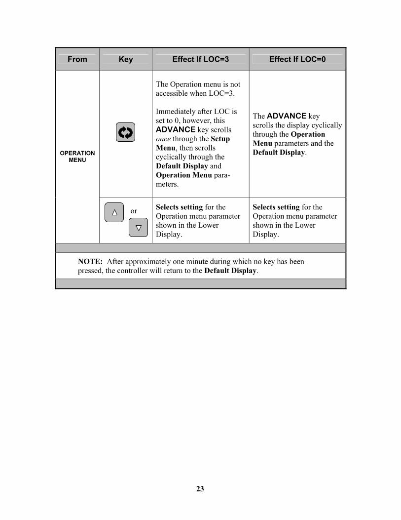
From Key Effect If LOC=3 Effect If LOC=0
The Operation menu is not accessible when LOC=3. Immediately after LOC is set to 0, however, this ADVANCE key scrolls once through the Setup Menu, then scrolls cyclically through the Default Display and Operation Menu para-meters.
The ADVANCE key scrolls the display cyclically through the Operation Menu parameters and the Default Display. OPERATION
MENU
Selects setting for the Operation menu parameter shown in the Lower Display.
Selects setting for the Operation menu parameter shown in the Lower Display.
NOTE: After approximately one minute during which no key has been pressed, the controller will return to the Default Display.
23
or

_____________________________________________________________________________ Hotpack Series 1750 – 1753 , 1758 Incubators & Humidity Chambers
24
MAINTENANCE
DOOR GASKETS — Periodic cleaning of the door gaskets is recommended. Although Hotpack gasket material resists degradation by oils and greases, accumulated dirt or deposits should be cleaned with a mild soapy detergent. CONDENSER / COMPRESSOR (Refrigerated units only) — Always keep the condenser / compressor components free from dust and dirt buildup, which can lower refrigeration efficiency.
Every three (3) months: Inspect the condenser / compressor equipment area.
Every six (6) months (or more frequently, if required): Vacuum, then clean this area.
CONDENSATE DRAIN (Humidified units only) — To keep the chamber’s bottom drain clean and free flowing:
Every three (3) months: Inspect drain.
Every six (6) months: To prevent growth and buildup that could form clogs, flush and clean the drain thoroughly.
DRYER (Dehumidification-equipped units only) — Follow directions in the dryer manufacturer’s manual. For the P/N 222353 Compressed-Air-Powered Dryer, see also Addendum #048 for more information. VAPOR GENERATOR MAINTENANCE (Humidified units only) — Buildup of concentrated impurities on the heating elem-ents can affect humidifier performance. Element longevity is directly related to water quality (see page 5 for specifications) and the performance of regular maintenance described below. Drain and clean the humidification system according to the following procedure (see pages 11 and 12 for component locations): Monthly Water Flush.
1. Turn off all power to the unit.
2. Turn off water supply.
3. Remove the upper rear cabinet panel, exposing the vapor generator and water reservoir area.
4. Drain the water reservoir by opening the drain valve located near the drain hose connection.
5. Close the drain valve.

_____________________________________________________________________________ Hotpack Series 1750 – 1753 , 1758 Incubators & Humidity Chambers
25
6. Pour 1 quart (950 ml) of system water into the reservoir.
7. Drain, then re-close the drain valve.
8. Repeat steps 6 and 7 at least three more times.
9. Restore water supply to the water reservoir.
10. Reinstall the cabinet panel and restart the unit.
Annual Acid Flush.
1. Turn off all power to the unit.
2. Turn off water supply.
3. Remove the upper rear cabinet panel, exposing the vapor generator and water reservoir area.
4. Drain the water reservoir by opening the drain valve located near the drain connection.
5. Close the drain valve.
6. Pour 1 quart (950 ml) of 8% phosphoric acid into the water reservoir and allow the solution to act for 15 minutes.
7. Drain, then re-close the drain valve.
8. Restore water supply to the water reservoir.
9. Drain and refill the water reservoir at least two more times before restoring the cabinet panel and restarting the unit.
Most humidity generator malfunctions are the result of inadequate water quality (hard water or water with too high a resistivity). If water is suspect, discontinue operating the unit until the water quality is verified. Continued use of out-of-specification water will damage the humidifier and void the warranty.
WARNING: To prevent injury, wear gloves and eye protec-tion and follow all safety instructions on the phosphoric acid container.

_____________________________________________________________________________ Hotpack Series 1750 – 1753 , 1758 Incubators & Humidity Chambers
26
____________________________________________________ STAINLESS STEEL CLEANING — Although stainless steel is corrosion resistant, it is not “corrosion proof.” Periodic main-tenance is required to prolong its life and appearance.
For regular cleaning, wipe stainless steel surfaces regularly with mild soapy water, rinsing and drying thoroughly. To clean rust-type discoloration, a more thorough cleaning may be necessary. To clean rust-type discoloration:
1. Prepare a solution of 20% nitric and 1.5 % hydrofluoric acid. If preferred, a 2 – 5% solution of warm oxalic acid may be used.
2. Swab solution over surface, allowing it to remain until all rust is loosened (usually 1-2 minutes). Immediately flush surface with clean water until all acid is removed.
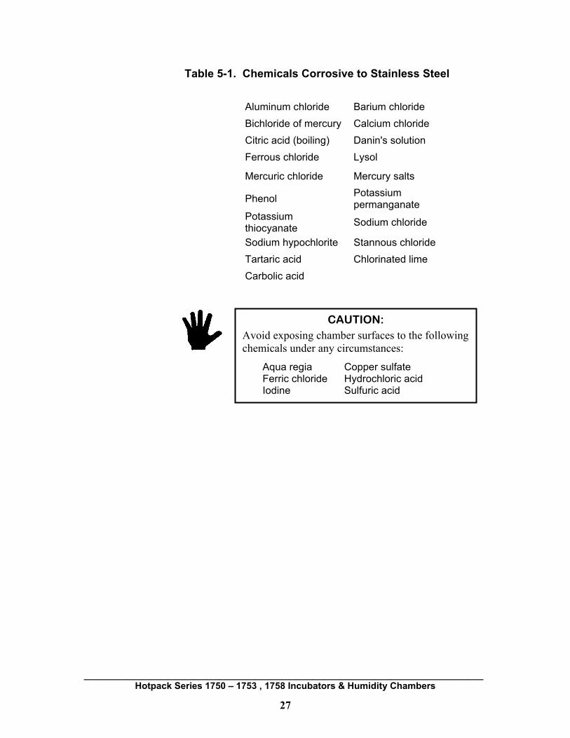
3. Re-flush and thoroughly dry all surfaces. STAINLESS STEEL PROTECTION — The chemicals listed in Table 5-1 will corrode stainless steel. Avoid exceeding four (4) hours of contact time between these chemicals and unit stainless steel surfaces. Immediately after contact, clean the stainless steel surface.
CAUTION: Wear protective clothing and gloves when working with any of the chemicals listed below. Always read the label on the container and follow the manufacturer's directions for safe use.
CAUTION: Work ONLY in a well-ventilated area.
_____________________________________________________________________________ Hotpack Series 1750 – 1753 , 1758 Incubators & Humidity Chambers
27
Table 5-1. Chemicals Corrosive to Stainless Steel
Aluminum chloride Barium chloride Bichloride of mercury Calcium chloride Citric acid (boiling) Danin's solution Ferrous chloride Lysol
Mercuric chloride Mercury salts
Phenol Potassium permanganate
Potassium thiocyanate Sodium chloride
Sodium hypochlorite Stannous chloride Tartaric acid Chlorinated lime Carbolic acid
CAUTION: Avoid exposing chamber surfaces to the following chemicals under any circumstances:
Aqua regia Copper sulfate Ferric chloride Hydrochloric acid Iodine Sulfuric acid

_____________________________________________________________________________ Hotpack Series 1750 – 1753 , 1758 Incubators & Humidity Chambers
28
TROUBLESHOOTING
Deviation Alarms An audible alarm with a lower display flashing “LO” or “HI” (alternating with the set point value) indicates that the actual temperature or humidity is outside a deviation limit set in the Operation menu. Setup and Operation menu parameters are configured at the Hotpack factory to provide unlatched deviation alarms with silencing enabled and with Manual mode lockout. Alarms self-silence/reset without operator intervention if the deviating temperature or humidity reenters acceptable range. To manually silence a deviation alarm (under the Hotpack factory default configuration) press the INFINITY key once. NOTE: If LOC has been changed to a number less than the Hotpack setting of 3, accidentally pressing the INFINITY key twice will place the unit into Manual mode (indicated by the % LED being solidly illumi-nated). If this occurs, restore the unit to Auto mode by pressing the INFINITY key two more times in quick succession. For more about Manual mode, see Note #2 on page 22.
Troubleshooting Table The following table lists possible problem situations and suggests probable causes and corrective actions. Should an error or mal-function persist, contact SP TechCare for assistance.
DANGER: Service should be performed only by qualified service personnel. Before servicing any electrical or mechanical components, disconnect the unit from its electrical power source. If electrical power is required for service, exercise extreme caution because line voltage is present even when the unit’s power switch is turned OFF.

_____________________________________________________________________________ Hotpack Series 1750 – 1753 , 1758 Incubators & Humidity Chambers
29
PROBLEM
POSSIBLE CAUSE
ACTION
External breaker tripped or fuse blown.
Reset breaker or replace fuse. Observe for recurrence. Assure that circuit amperage rating can accommodate all connected equipment.
Bad electrical connection.
Inspect power cable or hard-wired power connection (whichever is applicable).
UNIT WILL NOT FUNCTION.
Power problem. Check voltage supply.
Controller set point is set too low (heat is not necessary).
Verify set point value is correct.
UNIT FUNCTIONS WITHOUT HEAT.
No voltage present at power module. See electrical schematic. Check.
Controller set point is set too high (refrig-eration is unnecessary).
Verify set point value is correct.
REFRIG switch is in the OFF position. Turn REFRIG switch ON.
UNIT FUNCTIONS WITHOUT REFRIGERATION.
Unit is in defrost cycle. Allow defrost cycle to complete.

_____________________________________________________________________________ Hotpack Series 1750 – 1753 , 1758 Incubators & Humidity Chambers
30
PROBLEM
POSSIBLE CAUSE
ACTION
Humidity controller’s set point is set too low (humidification is unnecessary).
Verify set point value is correct.
Vapor generator water reservoir low, empty, or inadequately pressurized.
Check water level. Verify adequate water pressure is supplied to reservoir.
UNIT FUNCTIONS WITHOUT HUMIDITY.
Inadequate water quality.
Check water for conformance to specifications (see page 5), correct any water deficiency, and perform humidifier maintenance (see page 24). Discontinue operating the unit until the water problem is resolved. Continued use of out-of-specification water will damage the humidifier and void the warranty.
LOWER DISPLAY VALUE IS VERY DIFFERENT FROM SET POINT, “%” LED IS ON, AND CONTROL SEEMS UNREGULATED.
Unit is in Manual mode.
To return to Auto mode from Manual mode, press the INFINITY key two times in quick succession. For more about Manual mode, see Note #2 on page 22.
TEMPERATURE DEVIATION ALARM OFTEN SOUNDS WHEN DOOR IS OPENED.
“ALO” or “AHI” deviation alarm parameter is set too close to zero for your facility’s door-opening frequency or duration patterns.
Make the Low Limit parameter (ALO) more negative or the High Limit parameter (AHI) more positive in the Operation menu, as described on page 19.

_____________________________________________________________________________ Hotpack Series 1750 – 1753 , 1758 Incubators & Humidity Chambers
31
PROBLEM
POSSIBLE CAUSE
ACTION
LOWER DISPLAY SHOWS “ER #” MESSAGES (SEE BELOW).
Errors pertaining to sensor, memory, or other electronic malfunction.
Turn off power to the unit, wait a minute, then restore power. If the alarm recurs upon repowering, contact SP TechCare.
Measurement instrumen-tation not in calibration or not traceable to N.I.S.T. or other applicable standard.
Verify instrumentation accuracy and traceability.
The correct Calibration Offset value has been changed or lost through a memory failure.
The CAL parameter may be checked via the Operation menu, as described on page 20. If a record of Calibration Offset value has been kept, ensure that this value remains in memory. If incorrect, re-enter the correct CAL value.
TEMPERATURE OR HUMIDITY VERIFICATION DISAGREES WITH VALUE DISPLAYED.
A new Calibration Offset is necessary.
Calibrate the unit to a new Calibration Offset value as described on page 20.
Controller Error Code Messages Four dashes (----) appearing in the upper display indicates a controller error. The error code is visible in the lower display. Electrical noise (or a noise event), vibration, or excessive environ-mental moisture or temperature may cause controller errors to occur. If the cause of an error is not otherwise apparent, check for the above possibilities and correct if applicable.

_____________________________________________________________________________ Hotpack Series 1750 – 1753 , 1758 Incubators & Humidity Chambers
32
If any of the error messages described below persist after de-powering and then re-powering the unit, contact SP TechCare. The following error codes are reportable by the controller: ER2 — Sensor underrange error (applies only to temperature controllers). The sensor input generated a lower value than the allowable signal range or the A/D circuitry malfunctioned. ER4 — Configuration error. Possible microprocessor malfunction. ER5 — Non-volatile checksum error. The non-volatile memory checksum discovered a checksum error. Unless a momentary power interruption occurred while the unit was storing data, the non-volatile memory may be bad. ER6 — A/D underflow error. The most likely cause of this error is an open or reversed polarity sensor. ER7 — A/D overflow error. The most likely cause of this error is an open or reversed polarity sensor. For support, service, or to order replacement parts, contact SP TechCare:
Telephone: (877) 548-4666. Fax: (877) 693-9273.

_____________________________________________________________________________ Hotpack Series 1750 – 1753 , 1758 Incubators & Humidity Chambers
33
[THIS PAGE CONTAINS NO INFORMATION.]
_____________________________________________________________________________ Hotpack Series 1750 – 1753 , 1758 Incubators & Humidity Chambers
34
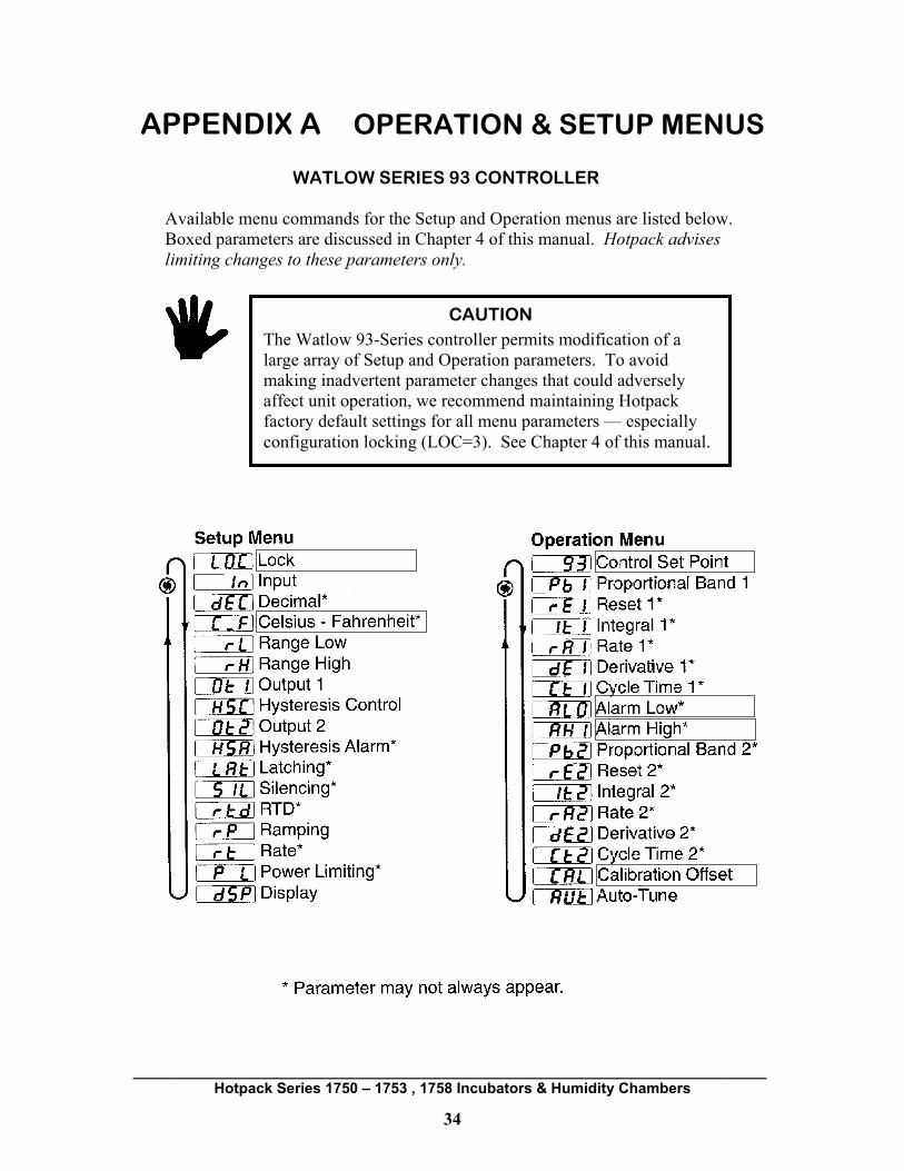
APPENDIX A OPERATION & SETUP MENUS
WATLOW SERIES 93 CONTROLLER Available menu commands for the Setup and Operation menus are listed below. Boxed parameters are discussed in Chapter 4 of this manual. Hotpack advises limiting changes to these parameters only.
CAUTION The Watlow 93-Series controller permits modification of a large array of Setup and Operation parameters. To avoid making inadvertent parameter changes that could adversely affect unit operation, we recommend maintaining Hotpack factory default settings for all menu parameters — especially configuration locking (LOC=3). See Chapter 4 of this manual.

_____________________________________________________________________________ Hotpack Series 1750 – 1753 , 1758 Incubators & Humidity Chambers
35
APPENDIX B: CONTROLLER DEFAULT SETTINGS (TYPICAL)
TEMPERATURE
Setup Menu Operation Menu Parameter Value Parameter Value
LOC 3 Pb1 2.0
In RT.D rE1 0.08
dEC - lt1 -
C_F C rA1 0.01
rL 00.0 dE1 -
rH 72.0 Ct1 1.0
Ot1 HT ALO -5.0
HSC 0.2 AHI 1.0
Ot2 DEA Pb2 -
HSA 0.1 rE2 -
Lat NLA lt2 -
SIL On rA2 -
rtd JIS dE2 -
rP OFF Ct2 -
rt - CAL 0.0*
PL 100.0 AUt 0
dSP Nor
∗ Note: The original factory offset value is specific to each individual unit. Record it for future reference.
_____________________________________________________________________________ Hotpack Series 1750 – 1753 , 1758 Incubators & Humidity Chambers
36
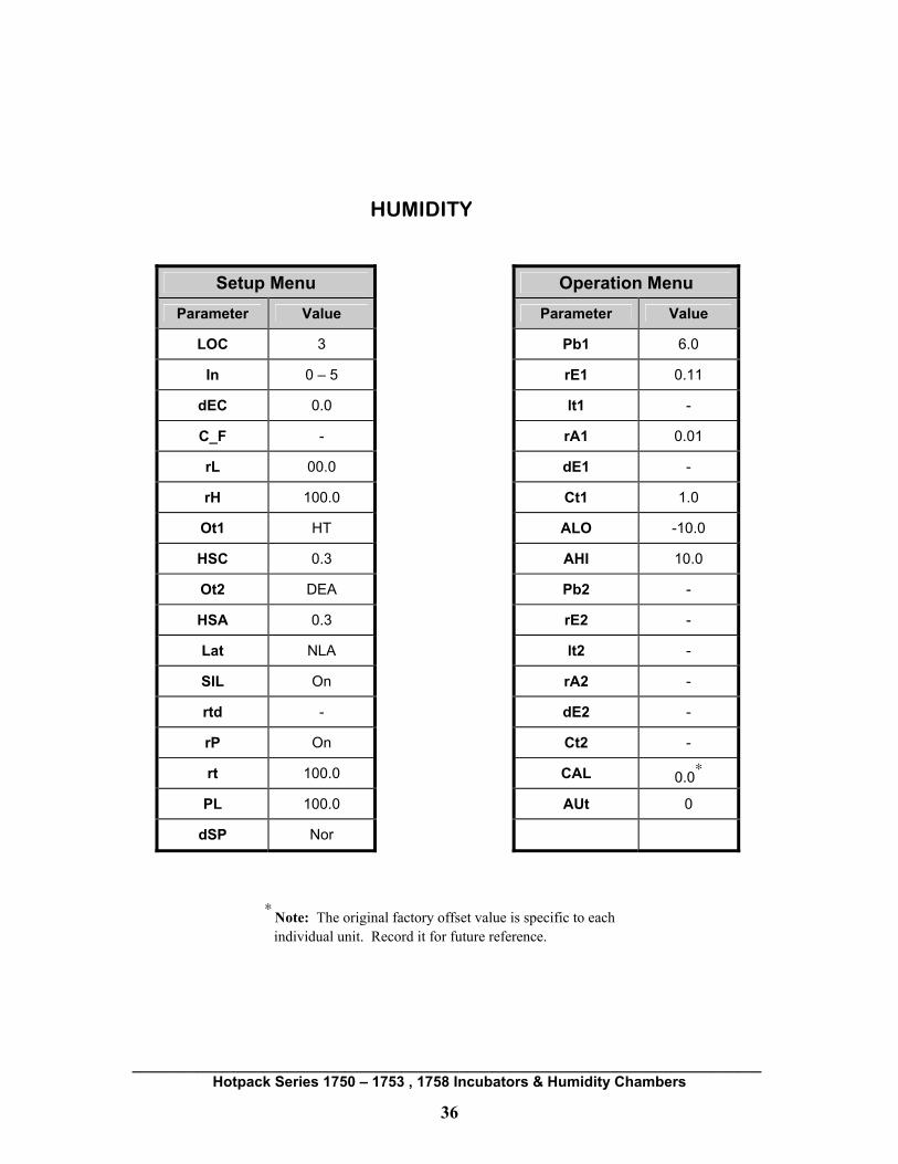
HUMIDITY
Setup Menu Operation Menu
Parameter Value Parameter Value
LOC 3 Pb1 6.0
In 0 – 5 rE1 0.11
dEC 0.0 lt1 -
C_F - rA1 0.01
rL 00.0 dE1 -
rH 100.0 Ct1 1.0
Ot1 HT ALO -10.0
HSC 0.3 AHI 10.0
Ot2 DEA Pb2 -
HSA 0.3 rE2 -
Lat NLA lt2 -
SIL On rA2 -
rtd - dE2 -
rP On Ct2 -
rt 100.0 CAL 0.0∗
PL 100.0 AUt 0
dSP Nor
∗ Note: The original factory offset value is specific to each individual unit. Record it for future reference.

37
APPENDIX C: ELECTRICAL SCHEMATICS & PARTS LISTS
MODEL 317502 / 317582 ELECTRICAL SCHEMATIC

38
MODEL 317502 / 317582 ELECTRICAL PARTS

39
MODEL 317512 / 317583 ELECTRICAL SCHEMATIC
(FOR REFRIGERATION SCHEMATIC: SEE PAGE 47).
40
MODEL 317512 / 317583 ELECTRICAL PARTS
41
MODEL 317522 / 417522 ELECTRICAL SCHEMATIC

42
MODEL 317522 / 417522 ELECTRICAL PARTS
43
MODEL 317532 / 417532 ELECTRICAL SCHEMATIC
(FOR REFRIGERATION SCHEMATIC: SEE PAGE 47).
44
MODEL 317532 / 417532 ELECTRICAL PARTS
45
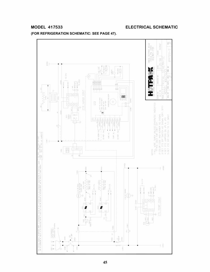
MODEL 417533 ELECTRICAL SCHEMATIC (FOR REFRIGERATION SCHEMATIC: SEE PAGE 47).

46
MODEL 417533 ELECTRICAL PARTS
47
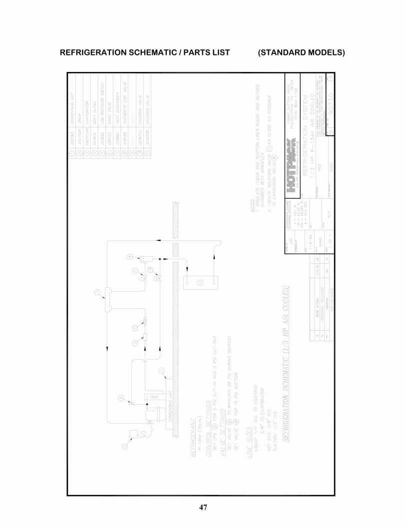
REFRIGERATION SCHEMATIC / PARTS LIST (STANDARD MODELS)

48
APPENDIX D: TEMPERATURE / HUMIDITY DATA (DRYER-EQUIPPED UNITS)
Units with a low-humidity option may be equipped with either an MG-90 rotary-bed desiccant dryer or P/N 222353 compressed-air-powered dryer. Typical empty-chamber performance for these units is presented below:
317532417532417533
317522417522
317532 417532 417533
+
MG-90 DRYER- EQUIPPED UNITS
MODELS MODELS
P/N 222353 COMPRESSED-AIR-POWERED DRYER
MG-90 REGENERATED ROTARY-BED DRYER

49
APPENDIX E: SERVICE SAFETY ASSURANCE FORM
Use this form to request authorization to return and/or process the following: ________________________ ________________________ _____________________ Model Name Model Number Serial Number Before HOTPACK issues authorization for return and/or processing of the product identified above, the following information must be provided by a qualified and responsible representative of your organization: Was the product ever exposed to (or did it ever contain) toxic, biohazardous, or otherwise harmful materials? YES_______ NO_______ If yes, please completely identify all such materials and answer the following questions:
( ) Poisonous Material ( ) Radioactive Material ( ) Corrosive Material ( ) Biological / Infectious Substance ( ) Mercury ( ) Flammable / Combustible Material ( ) Carcinogen ( ) Oxidizer ( ) Acetonitrile _____________________________ ( ) Other Material Types: Please supply Material Safety Data Sheets if available. (Use additional sheets if necessary):
_____________________________________________________________________________________________________
_____________________________________________________________________________________________________
Has the product been properly cleansed or treated so that it is now safe for human handling? YES___ NO___ Are there any additional safety precautions that should be taken? YES_____ (Describe in detail below) NO_____
____________________________________________________________________________________________________
____________________________________________________________________________________________________
HOTPACK relies on the accuracy and completeness of this information to protect our employees from injury by exposure to toxic, hazardous, infectious, or otherwise harmful materials. It is imperative that you provide HOTPACK with all necessary information. Name__________________________________ Signature_____________________________________
Title___________________________________ Date_________________________________________
Company_______________________________ Telephone / E-Mail_____________________________
Return or Fax to: HOTPACK ATT: SAFETY MANAGER 935 Mearns Road, Warminster, PA 18974 USA (877) 548-4666 / 001 (215) 672-7800 FAX: (877) 693-9273 / 001 (215) 672-1702 [email protected]
OFFICE USE ONLY REFERENCE JOB: ____________________ SANITIZATION REQUIRED: [ ] YES [ ] NO Reference PROCEDURE: ______________
SAFETY MGR: _______________________________ DATE:_______________________________
OPERATIONS MGR: _______________________________ DATE:_______________________________
Sanitization Safety Assurance Form HSP-01 Form 01 Revision: B 5/6/04

