section 00 0110 table of contents procurement and
TRANSCRIPT

Project No. 19-22812 Section 00 0110 - Page 1 of 2
Brown County Barkhausen Restroom Addition
SECTION 00 0110TABLE OF CONTENTS
PROCUREMENT AND CONTRACTING REQUIREMENTS1.01 DIVISION 00 -- PROCUREMENT AND CONTRACTING REQUIREMENTS
A. 00 0105 - Certifications PageB. 00 0110 - Table of Contents
SPECIFICATIONS2.01 DIVISION 01 -- GENERAL REQUIREMENTS
A. 01 3510 - Structural Testing and Special Inspection1. Attachment -- Structural Testing and Special Inspection Program Summary Schedule
2.02 DIVISION 02 -- EXISTING CONDITIONS 2.03 DIVISION 03 -- CONCRETE
A. 03 3000 - Cast-in-Place Concrete2.04 DIVISION 04 -- MASONRY 2.05 DIVISION 05 -- METALS
A. 05 5000 - Metal FabricationsB. 05 5213 - Pipe and Tube Railings
2.06 DIVISION 06 -- WOOD, PLASTICS, AND COMPOSITES A. 06 1000 - Rough CarpentryB. 06 1219 - Structural Insulated PanelsC. 06 1753 - Shop-Fabricated Wood TrussesD. 06 2000 - Finish CarpentryE. 06 4100 - Architectural Wood Casework
2.07 DIVISION 07 -- THERMAL AND MOISTURE PROTECTION A. 07 2100 - Thermal InsulationB. 07 2210 - Nailbase Insulation PanelsC. 07 2500 - Weather BarriersD. 07 3113 - Stone Coated Metal Roof ShinglesE. 07 4619 - Steel SidingF. 07 6200 - Sheet Metal Flashing and TrimG. 07 7123 - Manufactured Gutters and DownspoutsH. 07 9200 - Joint Sealants
2.08 DIVISION 08 -- OPENINGS A. 08 1113 - Hollow Metal Doors and FramesB. 08 1416 - Flush Wood DoorsC. 08 3100 - Access Doors and PanelsD. 08 4229 - Automatic EntrancesE. 08 5200 - Wood WindowsF. 08 6223 - Tubular SkylightsG. 08 7100 - Door HardwareH. 08 8000 - Glazing
2.09 DIVISION 09 -- FINISHES A. 09 0561 - Common Work Results for Flooring Preparation
ISS
UE
DA
TE
- 0
7/15
/201
9

Project No. 19-22812 Section 00 0110 - Page 2 of 2
Brown County Barkhausen Restroom Addition
B. 09 2116 - Gypsum Board AssembliesC. 09 3000 - TilingD. 09 6500 - Resilient FlooringE. 09 6700 - Fluid-Applied FlooringF. 09 7700 - Glassfiber Reinforced Plastic PanelsG. 09 9113 - Exterior PaintingH. 09 9123 - Interior Painting
2.10 DIVISION 10 -- SPECIALTIES A. 10 1400 - SignageB. 10 2113.19 - Plastic Toilet CompartmentsC. 10 2800 - Toilet, Bath, and Laundry AccessoriesD. 10 4400 - Fire Protection Specialties
2.11 DIVISION 11 -- EQUIPMENT 2.12 DIVISION 12 -- FURNISHINGS
A. 12 3600 - Countertops2.13 DIVISION 13 -- SPECIAL CONSTRUCTION 2.14 DIVISION 14 -- CONVEYING EQUIPMENT 2.15 DIVISION 21 -- FIRE SUPPRESSION 2.16 DIVISION 22 -- PLUMBING
A. 22 0010 - Basic Mechanical Plumbing RequirementsB. 22 0719 - Plumbing Piping InsulationC. 22 1005 - Plumbing PipingD. 22 1006 - Plumbing Piping SpecialtiesE. 22 3000 - Plumbing EquipmentF. 22 4000 - Plumbing Fixtures
2.17 DIVISION 23 -- HEATING, VENTILATING, AND AIR-CONDITIONING (HVAC) A. 23 0010 - Basic Mechanical HVAC RequirementsB. 23 0529 - Hangers and Supports for HVAC Piping and EquipmentC. 23 0593 - Testing, Adjusting, and Balancing for HVACD. 23 0713 - Duct InsulationE. 23 1126 - Facility Liquefied-Petroleum Gas PipingF. 23 3100 - HVAC Ducts and CasingsG. 23 3300 - Air Duct AccessoriesH. 23 3423 - HVAC Power VentilatorsI. 23 5400 - FurnacesJ. 23 6313 - Air Cooled Refrigerant Condensers
2.18 DIVISION 26 -- ELECTRICAL 2.19 DIVISION 27 -- COMMUNICATIONS 2.20 DIVISION 28 -- ELECTRONIC SAFETY AND SECURITY 2.21 DIVISION 31 -- EARTHWORK 2.22 DIVISION 32 -- EXTERIOR IMPROVEMENTS 2.23 DIVISION 33 -- UTILITIES
END OF SECTION
ISS
UE
DA
TE
- 0
7/15
/201
9

Project No. 19-22812 Section 00 0105 - Page 1 of 2
Brown County Barkhausen Restroom Addition
SECTION 00 0105CERTIFICATIONS PAGE
BROWN COUNTY BARKHAUSEN RESTROOM ADDITION SUAMICO, WISCONSIN - ISG NO. 19-22812
DATED THE 15TH DAY OF JULY, 2019
ISS
UE
DA
TE
- 0
7/15
/201
9

Project No. 19-22812 Section 00 0105 - Page 2 of 2
Brown County Barkhausen Restroom Addition
END OF SECTION
ISS
UE
DA
TE
- 0
7/15
/201
9
Project No. 19-22812 Section 01 3510 - Page 1 of 8
Brown County Barkhausen Restroom Addition
SECTION 01 3510STRUCTURAL TESTING AND SPECIAL INSPECTION
PART 1 GENERAL1.01 INTENT AND CONDITIONS
A. Intent1. Define and coordinate structural testing and special inspection services.2. Define and coordinate conventional testing and inspection services.3. Provide greater confidence that the specified work is constructed in compliance with the
contract documents and Chapter 17 of the 2015 International Building Code.4. Testing and Inspection services are intended to assist in determining probable compliance
of the work with requirements specified. These services do not relieve the Contractor ofresponsibility for compliance with the requirements of the contract documents.
B. Conditions1. If inspection of fabricator’s work is required, the Owner's representative may require
testing and inspection of the work at the plant, before shipment. Owner, Architect andStructural Engineer of Record (SER) reserve the right to reject material not complying withthe contract documents.
2. Testing and inspection shall be performed in accordance with the industry standard usedas the reference for the specific material or procedure unless other criteria are specified. In the absence of a referenced standard, tests shall be accomplished in accordance withgenerally accepted industry standards.
3. Work shall be checked as it progresses, but failure to detect any defective work ormaterials shall in no way prevent later rejection if defective work or materials arediscovered, nor shall it obligate Owner to accept such work.
1.02 RELATED REQUIREMENTSA. Refer to PART 3 for technical scope sections regarding specific qualifications, inspections,
tests, frequency and standards required.1.03 DEFINITIONS
A. Testing – Evaluation of systems, primarily requiring physical manipulation and analysis ofmaterials, in accordance with approved standards.
B. Inspection – Evaluation of systems, primarily requiring observation and engineering judgment.C. Structural Testing and Special Inspection – Structural Testing and Special Inspection Services
herein include items required by the 2015 International Building Code, and other items which inthe professional judgment of the Structural Engineer of Record, are critical to the integrity of thebuilding structure.
D. Conventional Testing and Inspection – Conventional Testing and Inspection Services hereindescribe those items not specially required by Code but may be considered essential to theproper performance of the building systems.
E. Architect of Record – The prime consultant in charge of overall design and coordination of theproject.
F. Structural Engineer of Record (SER) – The Licensed Engineer in responsible charge of thestructural design for the project.
G. Licensed Structural Engineer: – A professional engineer with education and experience in thedesign of structures similar to this project licensed to practice in the state in which the project islocated.
H. Testing Agency (TA) – The properly qualified firm performing testing services.I. Special Inspector (SI) – A properly qualified individual or firm performing special inspections.J. Building Official – The Officer or his duly authorized representative charged with the
administration and enforcement of the 2015 International Building Code.K. Continuous –The full-time observation of work requiring special inspection by an approved
special inspector who is present in the area where the work is being performed.
ISS
UE
DA
TE
- 0
7/15
/201
9
Project No. 19-22812 Section 01 3510 - Page 2 of 8
Brown County Barkhausen Restroom Addition
L. Periodic –The part-time or intermittent observation of work requiring special inspection by anapproved special inspector who is present in the area where the work is being performed.
1.04 REFERENCESA. ASTM E329-02 - Standard Specification for Agencies Engaged in the Testing and/or Inspection
of Materials Used in Construction.B. ASTM E43-02 - Standard Practice for Agencies Performing Nondestructive Testing.C. ASTM C1077-02 - Practice for Laboratories Testing Concrete and Concrete Aggregates for Use
in Construction and Criteria for Laboratory Evaluation.D. ASTM C1093-95 - Practice for Accreditation of Testing Agencies for Unit Masonry.E. ASTM D3740-01 - Practice for Minimum Requirements for Agencies Engaged in the Testing
and/or Inspection of Soil and Rock as Used in Engineering Design and Construction.F. AISC Steel Construction Manual 14th Edition (2010)G. 2015 International Building Code.H. See technical sections of PART 3 for specific references.
1.05 QUALIFICATIONSA. Testing Agency (TA) – The testing agency shall be an approved independent testing agency
acceptable to the Owner, Architect, SER and as noted below:1. Authorized to operate in the state in which the project is located and experienced with the
requirements and testing methods specified in the technical scope sections of PART 2.2. Meeting applicable requirements of Section 1.04 "References".3. Testing equipment shall be calibrated at reasonable intervals by devices of accuracy
traceable to either the National Bureau of Standards, or to accepted values of naturalphysical constants.
B. Special Inspector (SI) – The special inspector shall be under the direct supervision of aregistered civil/structural engineer, experienced with the type of work requiring structural testingand special inspection.1. The categories of special inspector are:
a. Special Inspector - Technical I, II, and III: Usually an employee of a testing agency.b. Special Inspector - Structural I and II: Preferably an employee of the SER's firm.
2. Unique special inspector requirements, for specific materials and system, are noted inrelated technical specification sections.
1.06 RESPONSIBILITIESA. Structural Testing and Special Inspection
1. Special Inspectors:a. Sign the Structural Testing and Special Inspection Summary Schedule in conjunction
with other responsible parties prior to commencement of construction.b. If requested, attend a pre-construction meeting to review the scope of structural
testing and special inspection.c. Test and/or inspect the work assigned for conformance with the building department
approved design drawings, specifications and applicable material and workmanshipprovisions of the Code. Perform testing and inspection in a timely manner to avoiddelay of work.
d. Bring discrepancies to the immediate attention of the contractor for correction, confirmthat they are corrected and, if uncorrected after a reasonable period of time, bring tothe attention of the Structural Engineer of Record, the Building Official, and to theArchitect.
e. Submit test and/or inspection reports to the Building Official, Contractor, the StructuralEngineer of Record, and other designated persons in accordance with the StructuralTesting and Special Inspection Summary Schedule.
f. Submit a final signed report stating whether the work requiring special inspection was,to the best of the inspector's knowledge, in conformance with the approved plans,specifications and the applicable workmanship provisions of the Code.
2. Testing Agency:
ISS
UE
DA
TE
- 0
7/15
/201
9

Project No. 19-22812 Section 01 3510 - Page 3 of 8
Brown County Barkhausen Restroom Addition
a. Sign the Structural Testing and Special Inspection Summary Schedule in conjunctionwith other responsible parties prior to commencement of construction.
b. If requested, attend a pre-construction meeting to review the scope of structuraltesting and special inspection.
c. When engaged as a special inspector, provide structural testing and specialinspection services as previously described.
3. Architect of Record (or other prime consultant):a. Complete and sign the Structural Testing and Special Inspection Summary Schedule
in conjunction with other responsible parties prior to commencement of construction. Provide a completed copy of the schedule to all signed parties including BuildingOfficial.
b. If appropriate, arrange and attend a pre-construction meeting to review the scope ofstructural testing and special inspection. Include Contractor, Building Official, SER,Testing Agency and other parties concerned.
c. Coordinate the flow of reports and related information to expedite resolution ofconstruction issues.
4. Structural Engineer of Record (SER):a. Identify items requiring structural testing and special inspection including special
cases.b. Define "type" of special inspector required for "description" of work indicated on the
structural testing and special inspection schedule.c. Complete and sign the Structural Testing and Special Inspection Summary Schedule
prior to commencement of construction.d. If requested, attend a pre-construction meeting to review the scope of structural
testing and special inspection.e. Review reports submitted by special inspectors.f. If engaged as a special inspector, provide structural testing and special inspection
services as previously described.5. Contractor:
a. Sign the Structural Testing and Special Inspection Summary Schedule in conjunctionwith other responsible parties prior to commencement of construction.
b. Coordinate efforts to gain signatures of all signing parties other than the Architect andStructural Engineer of Record (SER).
c. If requested, attend a pre-construction meeting to review the scope of structuraltesting and special inspection.
d. Post or make available the Structural Testing and Special Inspection SummarySchedule within its office at the job site. Also, provide adequate notification to thoseparties designated on the schedule so they may properly prepare for and scheduletheir work.
e. Provide the special inspectors access to the approved drawings and specifications atthe job site.
f. Review reports submitted by special inspectors.g. Retain at the job site all reports submitted by the special inspectors for review by the
building official upon request.h. Correct in a timely manner, deficiencies identified in inspection and/or testing reports.i. Provide the special inspector safe access to the work requiring inspection and/or
testing.j. Provide labor and facilities to provide access to the work and to obtain, handle and
deliver samples, to facilitate testing and inspection and for storage and curing of testsamples.
k. Verification of conformance of the work within specified construction tolerances issolely the Contractor's responsibility.
6. Fabricator:a. Sign the Structural Testing and Special Inspection Summary Schedule in conjunction
with other responsible parties prior to commencing construction.b. Submit a Certificate of Compliance to the Building Official, Special Inspector, and
Structural Engineer of Record that the work was performed in accordance with theapproved plans and specifications.
ISS
UE
DA
TE
- 0
7/15
/201
9

Project No. 19-22812 Section 01 3510 - Page 4 of 8
Brown County Barkhausen Restroom Addition
7. Building Official (Typical responsibilities noted for information only):a. Determine work, which in the Building Officials opinion, involves unusual hazards or
conditions in accordance with the 2015 International Building Code.b. Review special inspector qualifications.c. Accept and sign the completed Structural Testing and Special Inspection Summary
Schedule.d. Review all fabricators who perform work in their shop, which requires special
inspection.e. Review reports and recommendations submitted by the special inspectors.f. Review the "final signed reports" submitted by the special inspector(s). These
documents should be accepted and approved by the building department prior toissuance of a Certificate of Occupancy.
8. Owner:a. Establish direct funding to provide for cost of structural testing and special inspection
services.b. Provide special inspector with approved design drawings, specifications and approved
shop drawings.c. Provide special inspectors and testing agencies with full access to site at all times.d. Sign the Structural Testing and Special Inspection Summary Schedule in conjunction
with other responsible parties prior to commencement of construction.B. Conventional Testing and Inspection
1. Testing Agency:a. Test or inspect the work assigned, for conformance with building department
approved plans, specifications and applicable workmanship provisions of the 2015International Building Code.
b. Bring non-conforming items to the immediate attention of the Contractor, and ifuncorrected to the Architect of Record.
c. Submit test and/or inspection reports to the Architect of Record, the Contractor andother designated persons.
2. Contractor:a. Provide adequate notification to testing agency so they may properly prepare for and
schedule their work.b. Provide testing agency with access to the approved design drawings, approved shop
drawings and specifications at the job site.c. Correct in a timely manner, deficiencies identified in test and/or inspection reports.d. Provide testing agency with safe access to the work requiring testing and inspection.e. Provide labor and facilities to provide access to the work and to obtain and handle
samples, to facilitate testing and inspection and for storage and curing of testsamples.
f. Verification of conformance of the work within specified construction tolerances issolely the Contractor's responsibility.
3. Architect of Record (or other prime consultant):a. Coordinate the flow of reporting and related information to expedite resolution of
construction issues.C. Inspections by Building Official
1. Contractor shall provide adequate notice for inspections performed by the Building Official,as required by the 2015 International Building Code, and local ordinance.
D. Periodic Site Observations by Design Consultant1. Special structural testing and inspection, conventional testing and inspection, and periodic
inspections by the Building Official do not preclude the normal field involvement and siteobservations by Architect or Structural Engineer of Record, nor shall it relieve theContractor of any responsibility to complete the work in accordance with the approveddrawings and specifications.
E. Limits of Authority1. Testing agents and/or special inspectors may not waive or alter contract requirements, or
approve or accept any portion of the work unless specifically authorized by the Architect or
ISS
UE
DA
TE
- 0
7/15
/201
9

Project No. 19-22812 Section 01 3510 - Page 5 of 8
Brown County Barkhausen Restroom Addition
Structural Engineer of Record. They may not assume any duties of the Contractor, andthey have no authority to stop or reject "Work".
1.07 PAYMENTA. Owner shall directly employ and pay for services of the special inspectors to perform required
Structural Testing and Special Inspection.B. Owner shall employ and pay for services of the testing agency to perform required Conventional
Testing and Inspection.C. Unless noted otherwise, the Contractor shall provide and pay for all materials, samples,
mock-ups, and assemblies required for testing and inspection and shall pay for all shippingcosts related to delivery of this work. Testing agency will pay for shipping costs of samplestransported from site to lab.
D. If exploratory work is required to determine the cause of defects, the cost of such work shall bepaid by the Contractor, if the work is found to be defective, in the judgment of theArchitect/Engineer. Contractor shall reimburse the Owner for all costs incurred in this event.
E. Any tests required to qualify the Contractor, or the workmen for any phase of the work, shall beperformed at no additional cost to the Owner.
1.08 INSPECTION NOTICEA. Contractor shall provide minimum of 24 hours notice for all items requiring testing or inspection.
Items requiring testing and inspection services prior to or during placement shall not be placeduntil testing and inspection services are available. Items requiring testing and inspectionservices after placement shall not be enclosed or obscured until testing and inspection servicesare performed.
1.09 REPORTSA. Testing agency and/or special inspectors shall submit reports in accordance with the Structural
Testing and Special Inspection Summary Schedule and shall conduct and interpret tests andinspections and state in each report whether; (1) test specimens and observations comply withContract Documents, and specifically state any deviations, (2) record types and locations ofdefects found in work, (3) record work required and performed, to correct deficiencies.
B. Reports for structural testing and special inspection, shall be submitted in timely manner to theContractor, Building Official, SER, and Architect of Record.1. Submit reports for ongoing work, to provide the information noted below:
a. Date issued.b. Project title and number.c. Firm name and address.d. Name and signature of tester or inspector.e. Date and time of sampling.f. Date of test or inspection.g. Identification of product and specification section.h. Location in project, including elevations, grid location and detail.i. Type of test or inspections.j. Results of tests or inspections and interpretation of same.k. Observations regarding compliance with Contract Documents or deviations there
from.2. Submit a final signed report stating whether the work requiring special inspection was, to
the best of the inspector's knowledge, in conformance with the approved plans,specifications and the applicable workmanship provisions of the code.
C. Reports for conventional testing and inspection shall be submitted in a timely manner to theContractor and the Architect of Record.
1.10 FREQUENCY OF TESTING AND INSPECTIONA. For detailed requirements see technical sections of PART 3.
1.11 PROTECTION AND REPAIRA. Upon completion of testing, sample-taking, or inspection, the Contractor shall repair damaged
work and restore substrates and finishes to eliminate deficiencies, including deficiencies in the
ISS
UE
DA
TE
- 0
7/15
/201
9

Project No. 19-22812 Section 01 3510 - Page 6 of 8
Brown County Barkhausen Restroom Addition
visual qualities of exposed surfaces, as judged solely by the Architect/Engineer of Record. Protect work exposed by or for testing and/or inspection and protect repaired work. Repair andprotection is the Contractor's responsibility, regardless of the assignment of responsibility fortesting and/or inspection.
1.12 TESTS TO DEMONSTRATE QUALIFICATIONA. If the Contractor proposes a product material, method, or other system that has not been
pre-qualified, the Architect may require applicable tests, to establish a basis for acceptance orrejection. These tests will be paid for by the Contractor.
B. The Architect/Engineer of Record reserves the right to require certification or other proof thatthe system proposed, is in compliance with any tests, criteria or standards called for. Thecertificate shall be signed by a representative of an independent testing agency.
PART 2 MATERIALS (NOT USED)PART 3 SCOPE OF TESTING AND INSPECTION3.01 STRUCTURAL TESTING AND SPECIAL INSPECTION PROGRAM SUMMARY
A. The parties involved shall complete and sign the Structural Testing and Special InspectionSummary Schedule. The Program, including Summary Schedule, shall be submitted to thebuilding official for approval prior to issuance of a building permit. The competed scheduleincludes the following:1. A specific listing of the items requiring inspection and testing.2. The associated technical scope sections that define the applicable standards by which to
judge conformance with the approved plans and specifications in accordance with 2015International Building Code. The technical scope sections should also include the degreeor basis of inspection and testing; i.e., intermittent/will-call or full-time/continuous.
3. The frequency of reporting, i.e., weekly, monthly, per test/inspection, per floor, etc.4. The parties responsible for performing the inspection and testing work.5. The required acknowledgments by each designated party.
3.02 CONVENTIONAL TESTING AND INSPECTIONA. (Not Used)
3.03 STRUCTURAL TESTING AND SPECIAL INSPECTION STATEMENT OF SPECIALINSPECTIONSA. Refer to attached Program Summary Schedule for this project. It includes a schedule of
Special Inspection services applicable to this project and the identity of agencies to be retainedfor conducting these inspections and tests.
B. The Special Inspector shall keep records of all inspections and shall furnish inspection reportsto the Building Official, the Architect and Structural Engineer of Record. Discrepancies shall bebrought to the immediate attention of the Contractor for correction. If such discrepancies arenot corrected, the discrepancies shall be brought to the attention of the Building Official, theArchitect and SER. The Special Inspection program does not relieve the Contractor of his orher responsibilities.
C. Interim reports shall be submitted to the Building Official, Architect, and SER.D. A Final Report of Special Inspections documenting completion of all required Special
Inspections, testing and correction of any discrepancies noted in the inspections shall besubmitted prior to issuance of a Certificate of Use and Occupancy.
3.04 TECHNICAL SECTIONSA. Section 31 2200 - Earthwork - Grading, Excavation Filling
1. (Not Used)2. Definitions
a. Refer to PART 1 for standard definitions.b. Special Inspector – Technical
1) Technical I: Technician shall be under the direct supervision of a Technical III. Work shall be performed in a qualified geotechnical/testing laboratory.
ISS
UE
DA
TE
- 0
7/15
/201
9

Project No. 19-22812 Section 01 3510 - Page 7 of 8
Brown County Barkhausen Restroom Addition
2) Technical II: Technical with a minimum of 2 years experience, or a graduateengineer, and is an employee of a qualified and approved geotechnical/testinglaboratory, under the direct supervision of a Technical III.
3) Technical III: A civil/geotechnical engineer regularly engaged in this type of workwith a minimum of 4 years experience, licensed in the State in which the projectis located, and is an employee of a qualified and approved geotechnical/testinglaboratory. This licensed engineer shall review and approve all final field reports.
3. Structural Testing and Special Inspection Requirements (Item and Frequency andQualifications)a. Classification of materials used and encountered during construction per
ASTM:D2488 and ASTM:D2487. Technical Ib. Performance of laboratory testing of materials, as needed (Proctor, Sieve Analysis,
Atterberg Limits, Consolidation Test, etc.). Technical Ic. Field Density Tests: Technical Id. Provide periodic results of field compaction and laboratory work for general
compliance with Contract Documents and Geotechnical Reports. Technical Ie. Observe all subgrades/excavation bases below footings and slabs and verify design
bearing capacity is achieved. Technical IIf. Document presence of groundwater within excavations. Technical Ig. Provide reports of subgrade observations for general compliance with Contract
Documents and Geotechnical Report. Technical IIh. Verify cut and fill slopes as specified in the contract documents. Technical III
4. Conventional Testing and Inspections Requirementsa. Contractor shall verify that footings comply with frost depth requirements and shall
report any variances to the SER in a timely manner.B. Section 03 3000 - Cast-in-Place Concrete
1. Generala. Structural testing is required for all concrete. Thus, Special inspections as outlined
below are not required for the following items:1) Isolated spread footings of buildings three stories or less in height that are fully
supported on earth or rock.2) Strip footings of buildings three stories or less in height that are fully supported
on earth or rock, where the footings support walls of light frame construction, thefootings are designed in accordance with Table 1808.8, or the footing structuraldesign is based on a f 'c no greater than 2500 psi.
3) Non-structural slabs on grade, including prestressed slabs on grade wheneffective prestress in concrete is less than 150 pounds per square inch.
4) Concrete foundation walls constructed in accordance with Table 1807.1.6.2.2. Definitions
a. Refer to PART 1 for standard definitions.b. Special Inspector – Technical
1) Technical I: ACI Certified Grade I inspector. Inspector shall be employed by atesting laboratory, under the direct supervision of a Technical III.
2) Technical II: ACI Certified Grade II inspector. Inspector shall be employed by atesting laboratory, under the direct supervision of a Technical III.
3) Technical III: A civil/structural engineer regularly engaged in this type of work,with a minimum of 4 years experience and licensed in the State in which theproject is located and is an employee of a qualified and approved testinglaboratory. The licensed engineer shall review and approved all reports.
4) Testing laboratory shall have C.C.R.L. certification at the National Bureau ofStandards.
c. Special Inspector – Structural1) Structural I: Graduate civil/structural engineer, or other personnel acceptable to
the SER, with experience in the design of structural systems of this type. Inspections shall be performed under the direct supervision of a Structural II.
2) Structural II: Civil/structural engineer regularly engaged in the design ofstructural systems of this type, licensed in the State in which the project islocated. The licensed engineer shall review and approve all inspection reports.
ISS
UE
DA
TE
- 0
7/15
/201
9

Project No. 19-22812 Section 01 3510 - Page 8 of 8
Brown County Barkhausen Restroom Addition
3) Special Inspector - Structural may be an employee of the SER.3. Structural Testing and Special Inspection Requirements (Item and Frequency and
Qualifications)a. Sample and test all cast in place concrete; Technical I.
1) Prepare compression test specimens (ASTM C31), one set of four standardcylinders of concrete for each compressive strength test, mold and storecylinders for laboratory-cured specimens. Specimens shall be 4x8 cylindersexcept where an alternate size has been approved by the structural engineer.
2) Perform compressive strength tests (ASTM C39). One set of four cylinders foreach day's pour between one and 25 cubic yards. If a day's pour exceeds 25cubic yards, one set of four cylinders for each additional 50 cubic yards, orfraction thereof. One specimen at seven days, two at 28 days, and onespecimen retained in reserve for later testing if required. For post tensionedconcrete, make and test an additional cylinder at three days to verify strengthprior to stressing. (When frequency of testing will provide less than five strengthtests for a given class of concrete, conduct at least five strength tests fromrandomly selected batches. If fewer than five batches are used, conduct onetest from each batch.)
3) Slump (ASTM C143): One test at point of discharge for each set of compressiontest specimens; additional tests when concrete consistency appears to havechanged.
4) Air entrainment (ASTM C231): Test the first batch of air entrained concrete andone additional test for each set of compression test specimens.
5) Concrete Temperature: Test concrete temperature hourly when air temperatureis 40F and below and when 80F and above, and each time a set of compressiontest specimens is made.
b. On a periodic basis, perform concrete mix verification; Technical I.1) Verify mixer truck trip ticket conforms to approved mix design.2) Verify that total water added to mix on site does not exceed that allowed by
concrete mix design.3) Verify that concrete quality is indicative of adequate mixing time, consistency,
and relevant time limits. Technical Ic. On a continuous basis, inspect preparation and placement of all concrete.
1) Verify the following; Structural I:(a) Verify acceptable general condition of concrete base prior to placement.(b) Verify concrete has been sampled for required concrete tests.(c) Verify that concrete conveyance and depositing avoids segregation and
contamination.(d) Verify that concrete is properly consolidated.(e) Verify reinforcement remains at proper location.(f) Unless noted, inspections shall be on a continuous basis. Inspections may
be performed on a periodic basis for the following types of work:d. On a periodic basis, observe protection and curing methods for all concrete requiring
inspections as outlined above; Structural I:1) Verify specified curing procedures are followed.2) Verify specified hot and cold weather procedures are followed.
e. On a continuous basis, inspect all bolts installed in concrete prior to and duringconcrete placement; Structural I:1) Verify specified size, type, spacing, configuration, embedment, and quantity.2) Verify proper concrete placement and means have been taken to achieve
consolidation around all bolts.4. Conventional Testing and Inspection Requirements
a. (Not Used)END OF SECTION
ISS
UE
DA
TE
- 0
7/15
/201
9
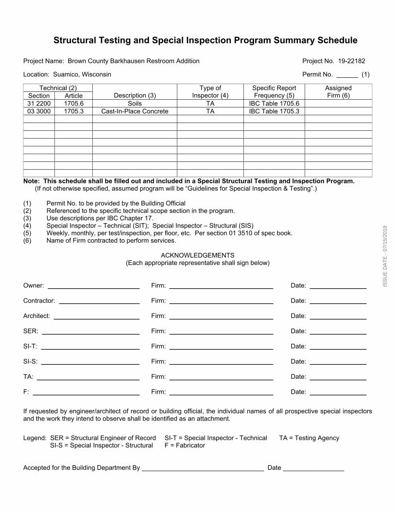
Structural Testing and Special Inspection Program Summary Schedule
Project Name: Brown County Barkhausen Restroom Addition Project No. 19-22182
Location: Suamico, Wisconsin Permit No. ______ (1)
Technical (2)Section Article Description (3)
Type ofInspector (4)
Specific ReportFrequency (5)
AssignedFirm (6)
31 2200 1705.6 Soils TA IBC Table 1705.603 3000 1705.3 Cast-In-Place Concrete TA IBC Table 1705.3
Note: This schedule shall be filled out and included in a Special Structural Testing and Inspection Program.(If not otherwise specified, assumed program will be “Guidelines for Special Inspection & Testing”.)
(1) Permit No. to be provided by the Building Official(2) Referenced to the specific technical scope section in the program.(3) Use descriptions per IBC Chapter 17.(4) Special Inspector – Technical (SIT); Special Inspector – Structural (SIS)(5) Weekly, monthly, per test/inspection, per floor, etc. Per section 01 3510 of spec book.(6) Name of Firm contracted to perform services.
ACKNOWLEDGEMENTS(Each appropriate representative shall sign below)
Owner: Firm: Date:
Contractor: Firm: Date:
Architect: Firm: Date:
SER: Firm: Date:
SI-T: Firm: Date:
SI-S: Firm: Date:
TA: Firm: Date:
F: Firm: Date:
If requested by engineer/architect of record or building official, the individual names of all prospective special inspectors and the work they intend to observe shall be identified as an attachment.
Legend: SER = Structural Engineer of Record SI-T = Special Inspector - Technical TA = Testing Agency SI-S = Special Inspector - Structural F = Fabricator
Accepted for the Building Department By __________________________________ Date _________________
ISS
UE
DA
TE
- 0
7/15
/201
9

ISS
UE
DA
TE
- 0
7/15
/201
9

Project No. 19-22812 Section 03 3000 - Page 1 of 8
Brown County Barkhausen Restroom Addition
SECTION 03 3000CAST-IN-PLACE CONCRETE
PART 1 GENERAL1.01 SECTION INCLUDES
A. Concrete formwork.B. Floors and slabs on grade.C. Concrete foundation walls.D. Concrete reinforcement.E. Joint devices associated with concrete work.F. Miscellaneous concrete elements, including bollards and stairs.G. Concrete curing.H. Concrete finishing.
1. Floor surfaces to be left exposed.1.02 RELATED REQUIREMENTS
A. Section 07 9200 - Joint Sealants: Products and installation for sealants and joint fillers for sawcut joints and isolation joints in slabs.
B. Section Division 22 - Plumbing Piping Specialties: Mechanical items for casting into concrete.C. Section Division 26 - Grounding and Bonding for Electrical Systems: Electrical items for casting
into concrete. Coordinate location with electrical contractor.D. Section Division 32 - Exterior Concrete Flatwork. Refer to concrete flatwork for all aspects of
exterior concrete flatwork except stoops, aprons, and any other concrete element bearing onthe building's foundation walls.
1.03 REFERENCE STANDARDSA. ACI 211.1 - Standard Practice for Selecting Proportions for Normal, Heavyweight, and Mass
Concrete; 1991 (Reapproved 2009).B. ACI 301 - Specifications for Structural Concrete; 2010 (Errata 2012).C. ACI 302.1R - Guide for Concrete Floor and Slab Construction; 2004 (Errata 2007).D. ACI 302.2R - Guide for Concrete Slabs that Receive Moisture-Sensitive Flooring MaterialsE. ACI 304R - Guide for Measuring, Mixing, Transporting, and Placing Concrete; 2000.F. ACI 305R - Hot Weather Concreting; 2010.G. ACI 306R - Cold Weather Concreting; 2010.H. ACI 308R - Guide to Curing Concrete; 2001 (Reapproved 2008).I. ACI 318 - Building Code Requirements for Structural Concrete and Commentary; 2011.J. ASTM A615/A615M - Standard Specification for Deformed and Plain Carbon-Steel Bars for
Concrete Reinforcement; 2016.K. ASTM C1602/C1602M - Standard Specification for Mixing Water Used in the Production of
Hydraulic Cement Concrete; 2012.L. ASTM C33/C33M - Standard Specification for Concrete Aggregates; 2016.M. ASTM C39/C39M - Standard Test Method for Compressive Strength of Cylindrical Concrete
Specimens; 2016b.N. ASTM C94/C94M - Standard Specification for Ready-Mixed Concrete; 2015.O. ASTM C109/C109M - Standard Test Method for Compressive Strength of Hydraulic Cement
Mortars (Using 2-in. or (50-mm) Cube Specimens); 2016a.P. ASTM C150/C150M - Standard Specification for Portland Cement; 2016.Q. ASTM C171 - Standard Specification for Sheet Materials for Curing Concrete; 2016.R. ASTM C173/C173M - Standard Test Method for Air Content of Freshly Mixed Concrete by the
Volumetric Method; 2014.
ISS
UE
DA
TE
- 0
7/15
/201
9

Project No. 19-22812 Section 03 3000 - Page 2 of 8
Brown County Barkhausen Restroom Addition
S. ASTM C260/C260M - Standard Specification for Air-Entraining Admixtures for Concrete; 2010a.T. ASTM C618 - Standard Specification for Coal Fly Ash and Raw or Calcined Natural Pozzolan
for Use in Concrete; 2015.U. ASTM C685/C685M - Standard Specification for Concrete Made by Volumetric Batching and
Continuous Mixing; 2014.V. ASTM C1059/C1059M - Standard Specification for Latex Agents for Bonding Fresh to
Hardened Concrete; 2013.W. ASTM C1240 - Standard Specification for Silica Fume Used in Cementitious Mixtures; 2014.X. ASTM E1155 - Standard Test Method for Determining F(F) Floor Flatness and F(L) Floor
Levelness Numbers; 1996 (Reapproved 2008).Y. ASTM E1643 - Standard Practice for Selection, Design, Installation and Inspection of Water
Vapor Retarders Used in Contact with Earth or Granular Fill Under Concrete Slabs; 2011.Z. ASTM E1745 - Standard Specification for Plastic Water Vapor Retarders Used in Contact with
Soil or Granular Fill under Concrete Slabs; 2011.1.04 SUBMITTALS
A. See Section 01 3000 - Administrative Requirements, for submittal procedures.B. Product Data: Submit manufacturers' data on manufactured products showing compliance with
specified requirements and installation instructions.C. Mix designs: Submit mix design for each mix showing compliance with specified requirements.D. Test Reports: Submit report for each test or series of tests specified.E. Manufacturer's Installation Instructions: For concrete accessories, indicate installation
procedures and interface required with adjacent construction.F. Project Record Documents: Accurately record actual locations of embedded utilities and
components that will be concealed from view upon completion of concrete work.1.05 QUALITY ASSURANCE
A. Perform work of this section in accordance with ACI 301 and ACI 318.B. Follow recommendations of ACI 305R when concreting during hot weather.C. Follow recommendations of ACI 306R when concreting during cold weather.
PART 2 PRODUCTS2.01 FORMWORK
A. Form Materials: Contractor's choice of standard products with sufficient strength to withstandhydrostatic head without distortion in excess of permitted tolerances.1. Form Facing for Exposed Finish Concrete: Contractor's choice of materials that will
provide smooth, stain-free final appearance.2. Form Coating: Release agent that will not adversely affect concrete or interfere with
application of coatings.3. Form Ties: Contractor's choice of standard product type that will leave no metal within
1-1/2 inches of concrete surface.2.02 REINFORCEMENT MATERIALS
A. Reinforcing Steel: ASTM A615/A615M, Grade 60 (60,000 psi).1. Type: Deformed billet-steel bars.2. Finish: Unfinished, unless otherwise indicated.
B. Reinforcement Accessories:1. Tie Wire: Annealed, minimum 16 gage, 0.0508 inch.2. Chairs, Bolsters, Bar Supports, Spacers: Sized and shaped for adequate support of
reinforcement during concrete placement.3. Do not use clay bricks or similar blocks/chunks of material as rebar chairs. Concrete
dobies as rebar chairs are acceptable.
ISS
UE
DA
TE
- 0
7/15
/201
9

Project No. 19-22812 Section 03 3000 - Page 3 of 8
Brown County Barkhausen Restroom Addition
2.03 CONCRETE MATERIALSA. Cement: ASTM C150/C150M, Type I - Normal Portland type.
1. Acquire cement for entire project from same source.B. Fine and Coarse Aggregates: ASTM C33/C33M.
1. Acquire aggregates for entire project from same source.2. Provide aggregate free of shale at all slab locations exposed to freeze/thaw action.
C. Fly Ash: ASTM C618, Class C or F.D. Calcined Pozzolan: ASTM C618, Class N.E. Silica Fume: ASTM C1240, proportioned in accordance with ACI 211.1.F. Water: ASTM C1602/C1602M; clean, potable, and not detrimental to concrete.
2.04 ADMIXTURESA. Chemical Admixture:
1. Manufacturers by concrete supplier:a. BASF: www.basf.com.b. Grace Construction Products: www.grace.com.c. Fritz-Pak: www.fritzpak.com.d. Mapei GRT: www.mapei.com.e. Sika Corporation U.S.: www.sika.com.f. Euclid Chemical: www.euclidchemical.com.g. Substitutions: See Section 01 6000 - Product Requirements.
B. Do not use chemicals that will result in soluble chloride ions in excess of 0.1 percent by weightof cement.
C. Admixtures shall comply with ASTM C494.D. Air Entrainment Admixture: ASTM C260/C260M.
2.05 ACCESSORY MATERIALSA. Underslab Vapor Barrier: Polyethylene or equivalent, complying with ASTM E 1745, Class A;
stated by manufacturer as suitable for installation in contact with soil or granular fill underconcrete slabs. The use of single ply polyethylene is prohibited.1. Acceptable Products:
a. Stego Wrap 15 mil, Class A by Stego Industries, LLC: www.stegoindustries.com.b. Griffolyn Vaporguard by Reef Industries, Inc.: www.reefindustries.com.c. Vaporflex 15 by Layfield, Inc.: www.layfieldgeosynthetics.com.d. WR Meadows 15 mil Perminator HP: www.wrmeadows.com.e. Substitutions: See Section 01 6000 - Product Requirements.
2. Vapor Barrier Accessories: Vapor retarder manufacturer's recommended tape, adhesive,mastic, prefabricated boots, etc., for sealing seams and penetrations in vapor barrier.
B. Non-Shrink Cementitious Grout: Premixed compound consisting of non-metallic aggregate,cement, water reducing and plasticizing agents.1. Minimum Compressive Strength at 48 Hours: 2,000 pounds per square inch.2. Minimum Compressive Strength at 28 Days: 7,000 pounds per square inch.
2.06 BONDING AND JOINTING PRODUCTSA. Latex Bonding Agent: Non-redispersible acrylic latex, complying with ASTM C1059 Type II.
1. Manufacturers:a. SpecChem, LLC; Strong Bond Acrylic Bonder: www.specchemllc.com/#sle.b. W. R. Meadows, Inc; ACRY-LOK-: www.wrmeadows.com/#sle.c. Substitutions: See Section 01 6000 - Product Requirements.
B. Expansion-Joint Filler: Polyethylene/polypropylene semi-rigid closed-cell backing complyingwith ASTM D 3575/ASTM D 8139/ASTM D 1751, 1/2 inch thick and full depth of slab less 1/2inch with peel-off feature. Provide product by BASF Construction Chemicals-Building Systems,W.R. Meadows, Namaco, or equivalent.1. Place peel-off feature at top of slab when sealants are specified. Remove peel-off portion
of expansion-joint filler prior to application of sealants.
ISS
UE
DA
TE
- 0
7/15
/201
9
Project No. 19-22812 Section 03 3000 - Page 4 of 8
Brown County Barkhausen Restroom Addition
2. Place peel off feature at bottom of slab when no sealants are specified.C. Slab Construction Joint Devices: Combination keyed joint form and screed, galvanized steel,
with rectangular or round knockout holes for conduit or rebar to pass through joint form at 6inches on center; ribbed steel stakes for setting.
2.07 CURING MATERIALSA. Liquid Membrane Curing Compound: ASTM C 309, Type 2, Class B, White Pigmented.
1. Product: L&M CURE R2 by Laticrete or approved equivalent.a. Other Approved Products:
1) SpecRez White by SpecChem.2. Application Locations: Exterior Concrete surfaces unless indicated otherwise. Finish
surfaces to a light broom finish prior to applying curing compound.B. Moisture-Retaining Sheet: ASTM C171.
1. White-burlap-polyethylene sheet, weighing not less than 3.8 ounces per square yard.2.08 CONCRETE MIX DESIGN
A. Proportioning Normal Weight Concrete: Comply with ACI 211.1 recommendations.B. Concrete Strength: Establish required average strength for each type of concrete on the basis
of field experience or trial mixtures, as specified in ACI 301.1. For trial mixtures method, employ independent testing agency acceptable to Architect for
preparing and reporting proposed mix designs.C. Admixtures: Add acceptable admixtures as recommended in ACI 211.1 and at rates
recommended or required by manufacturer.D. Materials In General: Do not use materials or combinations thereof that will result in a reaction
that is detrimental to the structural integrity or visual appearance of concrete.E. Normal Weight Concrete: Refer to structural notes on the drawings.
2.09 MIXINGA. On Project Site: Mix in drum type batch mixer, complying with ASTM C685/C685M. Mix each
batch not less than 1-1/2 minutes and not more than 5 minutes.B. Transit Mixers: Comply with ASTM C94/C94M.C. Adding Water: If concrete arrives on-site with slump less than suitable for placement, do not
add water that exceeds the maximum water-cement ratio or exceeds the maximum permissibleslump.
PART 3 EXECUTION3.01 EXAMINATION
A. Verify lines, levels, and dimensions before proceeding with work of this section.3.02 PREPARATION
A. Formwork: Comply with requirements of ACI 301. Design and fabricate forms to support allapplied loads until concrete is cured, and for easy removal without damage to concrete.
B. Verify that forms are clean and free of rust before applying release agent.C. Coordinate placement of embedded items with erection of concrete formwork and placement of
form accessories.D. Where new concrete is to be bonded to previously placed concrete, prepare existing surface by
cleaning and applying bonding agent in according to bonding agent manufacturer's instructions.1. Use latex bonding agent only for non-load-bearing applications.
E. In locations where new concrete is doweled to existing work, drill holes in existing concrete,insert steel dowels and pack solid with non-shrink grout.
F. Interior Slabs on Grade: Install vapor retarder under interior slabs on grade according to ASTME 1643 and manufacturer's written instructions; place sheets in position with longest dimensionparallel with direction of pour.1. Vapor Retarder Over Granular Fill: Install compactable granular fill before placing vapor
retarder as shown on the drawings. Do not use sand unless indicated otherwise.
ISS
UE
DA
TE
- 0
7/15
/201
9

Project No. 19-22812 Section 03 3000 - Page 5 of 8
Brown County Barkhausen Restroom Addition
2. Install vapor barrier in lieu of retarder at indicated locations. Refer to accessory materialsof this section.
3. Level and compact base material.4. Extend vapor barrier to the perimeter of the slab. If practicable, terminate it at the top of
the slab, otherwise (a) at a point acceptable to the Architect or (b) where obstructed byimpediments (such as dowels, waterstops, or any other site condition requiring earlytermination of the vapor barrier). At the point of termination, seal vapor barrier to thefoundation wall, grade beam or slab itself.
5. Lap joints minimum 6 inches and seal with manufacturer's recommended tape.6. Apply seam tape to a clean and dry vapor barrier.7. Seal joints, seams and penetrations watertight with manufacturer's recommended
products and follow manufacturer's written instructions.8. Avoid the use of non-permanent stakes driven through vapor retarder.9. If non-permanent stakes are driven through vapor retarder, repair as recommended by
vapor retarder manufacturer.10. Repair damaged vapor retarder before covering with vapor barrier material of similar (or
better) permeance, puncture and tensile.11. Install vapor barrier in lieu of retarder at indicated locations. Refer to accessory materials
of this section.3.03 INSTALLING REINFORCEMENT AND OTHER EMBEDDED ITEMS
A. Comply with requirements of ACI 301. Clean reinforcement of loose rust and mill scale, andaccurately position, support, and secure in place to achieve not less than minimum concretecoverage required for protection.
3.04 PLACING CONCRETEA. Place concrete in accordance with ACI 304R.B. Place concrete for floor slabs in accordance with ACI 302.1R.C. Ensure reinforcement, inserts, and other similar items will not be disturbed during concrete
placement.D. Finish floors level and flat, unless otherwise indicated, within the tolerances specified below.
3.05 SLAB JOINTINGA. Locate joints as indicated on drawings.
1. If no pattern is shown, contractor shall provide for 15 by 15 feet saw cut areas and shallcontact Engineer for exact locations of joints.
B. Anchor joint fillers and devices to prevent movement during concrete placement.C. Isolation Joints: Use preformed joint filler with removable top section for joint sealant, total
height equal to thickness of slab, set flush with top of slab.1. Install wherever necessary to separate slab from other building members, including
columns, walls, equipment foundations, footings, stairs, manholes, sumps, and drains.D. Saw Cut Contraction Joints: Saw cut joints before concrete begins to cool, within 24 hours after
placing; use 3/16 inch thick blade and cut at least 1 inch deep but not less than one quarter(1/4) the depth of the slab.1. Do not exceed 2 inches deep when/if slab thicknesses are greater than 8 inches.
E. Construction Joints: Where not otherwise indicated, use metal combination screed and keyform, with removable top section for joint sealant.
3.06 FLOOR FLATNESS AND LEVELNESS TOLERANCESA. Refer to structural notes on the drawings.
3.07 CONCRETE FINISHINGA. Repair surface defects, including tie holes, immediately after removing formwork.B. Unexposed Form Finish: Rub down or chip off fins or other raised areas 1/4 inch or more in
height.C. Exposed Form Finish: Rub down or chip off and smooth fins or other raised areas 1/4 inch or
more in height. Provide the following finishes only where/when indicated on the drawings:
ISS
UE
DA
TE
- 0
7/15
/201
9

Project No. 19-22812 Section 03 3000 - Page 6 of 8
Brown County Barkhausen Restroom Addition
1. Grout Cleaned Finish: Wet areas to be cleaned and apply grout mixture by brush or spray; scrub immediately to remove excess grout. After drying, rub vigorously with clean burlap,and keep moist for 36 hours.
D. Concrete Slabs: Finish to requirements of ACI 302.1R, and as follows:1. Other Surfaces to Be Left Exposed: Trowel as described in ACI 302.1R, minimizing
burnish marks and other appearance defects.a. Installation of sealant is recommended prior to installation of floor sealers to prevent
the need for cleaning of saw cut joints for proper sealant adhesion.b. Chemical Curer/Sealer/Dustproofer/Hardener(When Applicable): Apply product per
manufacturer's instructions after curing and protection procedures are complete.1) Acceptable Product:
(a) Laticrete: www.laticrete.com.(b) Product: L&M Dress & Seal; Acrylic Cure, Sealer, and Dustproofer.
(1) Location: Storage/mechanical/exposed areas not to receive otherfinishes.
(c) Product: L&M Seal Hard; Concrete Sealer, Densifier, Chemical Hardener.(1) Location: Garage/shop/warehouse type areas.
2) Other Acceptable Manufacturers:(a) Dayton Superior Corporation: www.daytonsuperior.com.(b) BASF Construction Chemicals-Building Systems:
www.buildingsystems.basf.com.(c) Ashford Formula by Curecrete Distribution, Inc: www.ashfordformula.com.(d) L.M. Scofield Company: www.scofield.com.(e) The Euclid Chemical Company: www.euclidchemical.com.
3) Substitutions: See Section 01 6000 - Product Requirements.E. In areas with floor drains, maintain floor elevation at walls; pitch surfaces uniformly to drains as
indicated on drawings.F. At exterior slabs, aprons, and other horizontal locations provide a light broom finish and liquid
membrane curing compound finish unless indicated otherwise.G. At interior slabs do not over trowel where concrete is to be left exposed to avoid slippery
surfaces when wet. Review finishing with Architect's representative prior to completing thework.
3.08 CURING AND PROTECTIONA. Comply with requirements of ACI 308R. Immediately after placement, protect concrete from
premature drying, excessively hot or cold temperatures, and mechanical injury.B. Maintain concrete with minimal moisture loss at relatively constant temperature for period
necessary for hydration of cement and hardening of concrete.C. Surfaces Not in Contact with Forms:
1. Initial Curing: Start as soon as free water has disappeared and before surface is dry. Keep continuously moist for not less than 7 days by saturated burlap unless notedotherwise.a. Saturated Burlap: Saturate burlap-polyethylene and place burlap-side down over floor
slab areas, lapping ends and sides; maintain in place.2. Final Curing: Begin after initial curing but before surface is dry.
3.09 FIELD QUALITY CONTROLA. An independent testing agency will perform field quality control tests, as specified in Section 01
4000 - Quality Requirements.B. Provide free access to concrete operations at project site and cooperate with appointed firm.C. Submit proposed mix design of each class of concrete to Architect for review prior to
commencement of concrete operations.D. Refer to Section 01 3510 - Structural Testing and Special Inspection Requirements for testing
requirements.
ISS
UE
DA
TE
- 0
7/15
/201
9

Project No. 19-22812 Section 03 3000 - Page 7 of 8
Brown County Barkhausen Restroom Addition
3.10 DEFECTIVE CONCRETEA. Test Results: The testing agency shall report test results in writing to Architect and Contractor
within 24 hours of test.B. Defective Concrete: Concrete not conforming to required lines, details, dimensions, tolerances
or specified requirements.1. Concrete damaged by the construction activities required to complete the Work of this
section shall also be considered defective concrete.C. Repair or replacement of defective concrete will be determined by the Architect. The cost of
additional testing shall be borne by Contractor when defective concrete is identified.D. Do not patch, fill, touch-up, repair, or replace exposed concrete except upon express direction
of Architect for each individual area.END OF SECTION
ISS
UE
DA
TE
- 0
7/15
/201
9

Project No. 19-22812 Section 03 3000 - Page 8 of 8
Brown County Barkhausen Restroom Addition
ISS
UE
DA
TE
- 0
7/15
/201
9

Project No. 19-22812 Section 05 5000 - Page 1 of 2
Brown County Barkhausen Restroom Addition
SECTION 05 5000METAL FABRICATIONS
PART 1 GENERAL1.01 SECTION INCLUDES
A. Shop fabricated steel items.1.02 RELATED REQUIREMENTS
A. Section 09 9113 - Exterior Painting: Paint finish.B. Section 09 9123 - Interior Painting: Paint finish.
1.03 REFERENCE STANDARDSA. ASTM A53/A53M - Standard Specification for Pipe, Steel, Black and Hot-Dipped, Zinc-Coated,
Welded and Seamless; 2012.B. ASTM A153/A153M - Standard Specification for Zinc Coating (Hot-Dip) on Iron and Steel
Hardware; 2016a.C. ASTM A307 - Standard Specification for Carbon Steel Bolts, Studs, and Threaded Rod 60 000
PSI Tensile Strength; 2014.D. ASTM A500/A500M - Standard Specification for Cold-Formed Welded and Seamless Carbon
Steel Structural Tubing in Rounds and Shapes; 2013.E. AWS A2.4 - Standard Symbols for Welding, Brazing, and Nondestructive Examination; 2012.F. AWS D1.1/D1.1M - Structural Welding Code - Steel; 2015.G. SSPC-Paint 15 - Steel Joist Shop Primer/Metal Building Primer; 1999 (Ed. 2004).H. SSPC-SP 2 - Hand Tool Cleaning; 1982 (Ed. 2004).
1.04 SUBMITTALSA. See Section 01 3000 - Administrative Requirements, for submittal procedures.B. Product Data: Provide data on all finishing products, including VOC content.C. Shop Drawings: Indicate profiles, sizes, connection attachments, reinforcing, anchorage, size
and type of fasteners, and accessories. Include erection drawings, elevations, and detailswhere applicable.1. Indicate welded connections using standard AWS A2.4 welding symbols. Indicate net weld
lengths.2. Indicate unit identification mark and location for each unique item.
PART 2 PRODUCTS2.01 MATERIALS - STEEL
A. Steel Tubing: ASTM A500/A500M, Grade B cold-formed structural tubing.B. Pipe: ASTM A 53/A 53M, Grade B Schedule 40, black finish.C. Bolts, Nuts, and Washers: ASTM A307, Grade A, galvanized to ASTM A153/A153M where
connecting galvanized components.D. Welding Materials: AWS D1.1/D1.1M; type required for materials being welded.E. Shop and Touch-Up Primer: SSPC-Paint 15, complying with VOC limitations of authorities
having jurisdiction.2.02 FABRICATION
A. Fit and shop assemble items in largest practical sections, for delivery to site.B. Mark each item with its identification mark. Use a non-permanent method at units that will
remain exposed; welding is not acceptable, it shall be ground smooth, filled, and primed by thesupplier at no additional cost to the Owner.
C. Fabricate items with joints tightly fitted and secured.D. Grind exposed joints flush and smooth with adjacent finish surface. Make exposed joints butt
tight, flush, and hairline. Ease exposed edges to small uniform radius.
ISS
UE
DA
TE
- 0
7/15
/201
9

Project No. 19-22812 Section 05 5000 - Page 2 of 2
Brown County Barkhausen Restroom Addition
E. Supply components required for anchorage of fabrications. Fabricate anchors and relatedcomponents of same material and finish as fabrication, except where specifically notedotherwise.
2.03 FABRICATED ITEMSA. Bollards: Steel pipe, concrete filled, crowned cap, as detailed; prime paint finish.B. Other items indicated on the drawings.
2.04 FINISHES - STEELA. Prime paint steel items.B. Prepare surfaces to be primed in accordance with SSPC-SP2 minimum.
1. Clean surfaces of rust, scale, grease, and foreign matter prior to finishing.2. Prime Painting: One coat.
a. Provide primer products indicated for surfaces to be primed and painted, Refer toSection 09 9113 - Exterior Painting and Section 09 9123 - Interior Painting.
2.05 FABRICATION TOLERANCESA. Squareness: 1/8 inch maximum difference in diagonal measurements.B. Maximum Offset Between Faces: 1/16 inch.C. Maximum Misalignment of Adjacent Members: 1/16 inch.D. Maximum Bow: 1/8 inch in 48 inches.E. Maximum Deviation From Plane: 1/16 inch in 48 inches.
2.06 CONCRETE ANCHORING SYSTEMSA. Approved Manufacturers/Products:
1. HILTI: www.us.hilti.com.2. MiTek: www.mitek-us.com.3. Powers: www.powers.com.4. Red Head: www.itwredhead.com.5. Simpson Strong-Tie: www.strongtie.com.
PART 3 EXECUTION3.01 EXAMINATION
A. Verify that field conditions are acceptable and are ready to receive work.3.02 PREPARATION
A. Clean and strip primed steel items to bare metal where site welding is required.B. Supply setting templates to the appropriate entities for steel items required to be cast into
concrete.3.03 INSTALLATION
A. Install items plumb and level, accurately fitted, free from distortion or defects.B. Provide for erection loads, and for sufficient temporary bracing to maintain true alignment until
completion of erection and installation of permanent attachments.C. Perform field welding in accordance with AWS D1.1/D1.1M.D. Obtain approval prior to site cutting or making adjustments not scheduled.E. After erection, prime welds, abrasions, and surfaces not shop primed, except surfaces to be in
contact with concrete.3.04 TOLERANCES
A. Maximum Variation From Plumb: 1/4 inch per story, non-cumulative.B. Maximum Offset From True Alignment: 1/4 inch.C. Maximum Out-of-Position: 1/4 inch.
END OF SECTION
ISS
UE
DA
TE
- 0
7/15
/201
9

Project No. 19-22812 Section 05 5213 - Page 1 of 2
Brown County Barkhausen Restroom Addition
SECTION 05 5213PIPE AND TUBE RAILINGS
PART 1 GENERAL1.01 SECTION INCLUDES
A. Stair railings and guardrails.1.02 RELATED REQUIREMENTS1.03 REFERENCE STANDARDS
A. ASTM A53/A53M - Standard Specification for Pipe, Steel, Black and Hot-Dipped, Zinc-Coated,Welded and Seamless; 2012.
B. ASTM A500/A500M - Standard Specification for Cold-Formed Welded and Seamless CarbonSteel Structural Tubing in Rounds and Shapes; 2013.
C. ASTM E985 - Standard Specification for Permanent Metal Railing Systems and Rails forBuildings; 2000 (Reapproved 2006).
PART 2 PRODUCTS2.01 RAILINGS - GENERAL REQUIREMENTS
A. Design, fabricate, and test railing assemblies in accordance with the most stringentrequirements of ASTM E985 and applicable local code.
B. Allow for expansion and contraction of members and building movement without damage toconnections or members.
C. Dimensions: See drawings for configurations and heights.D. Provide anchors and other components as required to attach to structure, made of same
materials as railing components unless otherwise indicated; where exposed fasteners areunavoidable provide flush countersunk fasteners.
E. Provide welding fittings to join lengths, seal open ends, and conceal exposed mounting boltsand nuts, including but not limited to elbows, T-shapes, splice connectors, flanges,escutcheons, and wall brackets.
2.02 STEEL RAILING SYSTEMA. Steel Tube: ASTM A500/A500M, Grade B cold-formed structural tubing.B. Steel Pipe: ASTM A 53/A 53M, Grade B Schedule 40, black finish.C. Welding Fittings: Factory- or shop-welded from matching pipe or tube; seams continuously
welded; joints and seams ground smooth.2.03 FABRICATION
A. Accurately form components to suit specific project conditions and for proper connection tobuilding structure.
B. Fit and shop assemble components in largest practical sizes for delivery to site.C. Fabricate components with joints tightly fitted and secured. Provide spigots and sleeves to
accommodate site assembly and installation.D. Welded Joints:
1. Exterior Components: Continuously seal joined pieces by continuous welds.2. Interior Components: Continuously seal joined pieces by continuous welds.3. Grind exposed joints flush and smooth with adjacent finish surface. Make exposed joints
butt tight, flush, and hairline. Ease exposed edges to small uniform radius.2.04 CONCRETE ANCHORING SYSTEMS
A. Approved Manufacturers/Products:1. HILTI: www.us.hilti.com.2. MiTek: www.mitek-us.com.3. Powers: www.powers.com.4. Red Head: www.itwredhead.com.5. Simpson Strong-Tie: www.strongtie.com.
ISS
UE
DA
TE
- 0
7/15
/201
9
Project No. 19-22812 Section 05 5213 - Page 2 of 2
Brown County Barkhausen Restroom Addition
PART 3 EXECUTION3.01 EXAMINATION
A. Verify that field conditions are acceptable and are ready to receive work.3.02 PREPARATION
A. Clean and strip primed steel items to bare metal where site welding is required.B. Supply items required to be cast into concrete with setting templates, for installation as work of
other sections.3.03 INSTALLATION
A. Install in accordance with manufacturer's instructions.B. Install components plumb and level, accurately fitted, free from distortion or defects, with tight
joints.C. Anchor railings securely to structure.
3.04 TOLERANCESA. Maximum Variation From Plumb: 1/4 inch per floor level, non-cumulative.B. Maximum Offset From True Alignment: 1/4 inch.C. Maximum Out-of-Position: 1/4 inch.
END OF SECTION
ISS
UE
DA
TE
- 0
7/15
/201
9

Project No. 19-22812 Section 06 1000 - Page 1 of 4
Brown County Barkhausen Restroom Addition
SECTION 06 1000ROUGH CARPENTRY
PART 1 GENERAL1.01 SECTION INCLUDES
A. Structural dimension lumber framing.B. Non-structural dimension lumber framing.C. Sheathing.D. Subflooring.E. Roofing nailers.F. Preservative treated wood materials.G. Miscellaneous framing and sheathing.H. Concealed wood blocking, nailers, and supports.I. Miscellaneous wood nailers, furring, and grounds.J. Optional Premanufactured Roof Sheathing & Insulation Panel Options.
1. Option 1: Refer to 06 1219 - Structural Insulated Panels.2. Option 2: Refer to 07 2210 - Nailbase Insulation Panels.3. Notes: Include and make adjustments to all related construction where premanufactured
panels are used in lieu of separate products for a complete installation. Account for leadtimes where premanufactured panels are used in lieu of separate Products to avoid delaysin project schedule.
4. New panels are to match existing height and or new construction shall work out so top ofnew roof sheathing aligns with existing roof sheathing.
1.02 REFERENCE STANDARDSA. AWC (WFCM) - Wood Frame Construction Manual for One- and Two-Family Dwellings; 2015.B. ASTM A153/A153M - Standard Specification for Zinc Coating (Hot-Dip) on Iron and Steel
Hardware; 2016a.C. AWPA U1 - Use Category System: User Specification for Treated Wood; 2012.D. PS 1 - Structural Plywood; 2009.E. PS 2 - Performance Standard for Wood-Based Structural-Use Panels; 2010.F. PS 20 - American Softwood Lumber Standard; 2010.G. WWPA G-5 - Western Lumber Grading Rules; 2011.
1.03 DELIVERY, STORAGE, AND HANDLINGA. General: Cover wood products to protect against moisture. Support stacked products to prevent
deformation and to allow air circulation. PART 2 PRODUCTS2.01 GENERAL REQUIREMENTS
A. Dimension Lumber: Comply with PS 20 and requirements of specified grading agencies.1. If no species is specified, provide any species graded by the agency specified; if no
grading agency is specified, provide lumber graded by any grading agency meeting thespecified requirements.
2. Grading Agency: Any grading agency whose rules are approved by the Board of Review,American Lumber Standard Committee (www.alsc.org) and who provides grading servicefor the species and grade specified; provide lumber stamped with grade mark unlessotherwise indicated.
2.02 DIMENSION LUMBER A. Grading Agency: Western Wood Products Association; WWPA G-5.B. Sizes: Nominal sizes as indicated on drawings, S4S.C. Moisture Content: S-dry or MC19.
ISS
UE
DA
TE
- 0
7/15
/201
9
Project No. 19-22812 Section 06 1000 - Page 2 of 4
Brown County Barkhausen Restroom Addition
1. Plates: MC15 or KD15.D. Stud Framing (2 by 2 through 2 by 6 ):
1. Grade: No. 2 & Btr.E. Joist, Rafter, and Small Beam Framing (2 by 6 through 4 by 16 ):F. Miscellaneous Framing, Blocking, Nailers, Grounds, and Furring:
1. Lumber: S4S, No. 2 or Standard Grade.2. Boards: Standard or No. 3.
2.03 LAMINATED LUMBER (STRUCTURAL COMPOSITE LUMBER)A. LVL materials: Laminated Veneer Lumber constructed of sheets of wood species or species
combinations coated with an exterior-type adhesive and in according to ICC EC ESR-1387.Provide products by TrusJoist or equivalent.1. E = 1,900,000 PSI2. FB = 2,600 PSI3. FV = 285 PSI
2.04 CONSTRUCTION PANELSA. Subflooring, T&G exterior glue plywood: Any PS 2 type, rated Sheathing.
1. Bond Classification: Exterior.2. Span Rating: 24.3. Performance Category: 3/4 PERF CAT.4. Installation: Review tile floor installation requirements of floor sheathing prior to installation
of subflooring.B. Roof Sheathing Lower, OSB: Any PS 2 type, rated Structural I Sheathing.
1. Bond Classification: Exposure 1.2. Span Rating: 24.3. Performance Category: 1/2 PERF CAT.
C. Roof Sheathing Upper, OSB: Any PS 2 type, rated Structural I Sheathing.1. Bond Classification: Exposure 1.2. Span Rating: 24.3. Performance Category: 5/8 PERF CAT.
D. Wall Sheathing, Plywood: Any PS 2 type.1. Bond Classification: Exposure 1.2. Grade: Structural I Sheathing.3. Span Rating: 16.4. Performance Category: 1/2 PERF CAT.5. Edge Profile: Square edge.
E. Miscellaneous Applications:1. Plywood Concealed From View But Located Within Exterior Enclosure: PS 1, C-C
Plugged or better, Exterior grade.2. Plywood Exposed to View But Not Exposed to Weather: PS 1, A-D, or better.3. Other Locations: PS 1, C-D Plugged or better.4. Electrical Component Mounting: APA rated sheathing, fire retardant treated.
2.05 ACCESSORIESA. Fasteners and Anchors:
1. Metal and Finish: Hot-dipped galvanized steel complying with ASTM A153/A153M forhigh humidity and preservative-treated wood locations, unfinished steel elsewhere.
2. Drywall Screws: Bugle head, hardened steel, power driven type, length three timesthickness of sheathing.
B. Sill Gasket on Top of Foundation Wall: 1/4 inch thick, plate width, closed cell plastic foam fromcontinuous rolls.
C. Subfloor Adhesives: Waterproof, air cure type, cartridge dispensed.
ISS
UE
DA
TE
- 0
7/15
/201
9

Project No. 19-22812 Section 06 1000 - Page 3 of 4
Brown County Barkhausen Restroom Addition
2.06 FACTORY WOOD TREATMENTA. Treated Lumber and Plywood: Comply with requirements of AWPA U1 - Use Category System
for wood treatments determined by use categories, expected service conditions, and specificapplications. 1. Preservative-Treated Wood: Provide lumber and plywood marked or stamped by an
ALSC-accredited testing agency, certifying level and type of treatment in accordance withAWPA standards.
B. Preservative Treatment:1. Manufacturers:
a. Arch Wood Protection, Inc: www.wolmanizedwood.com.b. Viance, LLC: www.treatedwood.com.c. Substitutions: See Section 01 6000 - Product Requirements.
PART 3 EXECUTION3.01 INSTALLATION - GENERAL
A. All wood exposed to or in contact with masonry or concrete shall be Preservative TreatedWood.
B. Where treated wood is used on interior, provide temporary ventilation during and immediatelyafter installation sufficient to remove indoor air contaminants.
C. Securely install blocking, size within 1/16 of required dimension, and install plumb and level.3.02 FRAMING INSTALLATION
A. Set structural members level, plumb, and true to line. Discard pieces with defects that wouldlower required strength or result in unacceptable appearance of exposed members.
B. Make provisions for temporary construction loads, and provide temporary bracing sufficient tomaintain structure in true alignment and safe condition until completion of erection andinstallation of permanent bracing.
C. Install structural members full length without splices unless otherwise specifically detailed.D. Comply with member sizes, spacing, and configurations indicated, and fastener size and
spacing indicated, but not less than required by applicable codes and AWC (WFCM) WoodFrame Construction Manual.
E. Construct double joist headers at floor and ceiling openings and under wall stud partitions thatare parallel to floor joists; use metal joist hangers unless otherwise detailed.
F. Frame wall openings with two or more studs at each jamb; support headers on cripple studs.3.03 BLOCKING, NAILERS, AND SUPPORTS
A. Provide framing and blocking members as indicated or as required to support finishes, fixtures,specialty items, and trim.
B. In walls, provide blocking attached to studs as backing and support for wall-mounted items,unless item can be securely fastened to two or more studs or other method of support isexplicitly indicated.
C. Provide the following specific non-structural framing and blocking:1. Cabinets and shelf supports.2. Wall brackets.3. Handrails.4. Grab bars.5. Towel and bath accessories.6. Wall-mounted door stops.7. Wall paneling and trim.8. Joints of rigid wall coverings that occur between studs.9. Wall mounted TVs.10. All other items indicated on the drawings and in the specifications.
3.04 INSTALLATION OF CONSTRUCTION PANELSA. Subflooring: Screw and glue to framing; staples are not permitted.
ISS
UE
DA
TE
- 0
7/15
/201
9

Project No. 19-22812 Section 06 1000 - Page 4 of 4
Brown County Barkhausen Restroom Addition
B. Roof Sheathing: Secure panels with long dimension perpendicular to framing members, withends staggered and over firm bearing.1. At long edges use sheathing clips where joints occur between roof framing members.2. Nail panels to framing; staples are not permitted.
C. Wall Sheathing: Secure with long dimension perpendicular to wall studs, with ends over firmbearing and staggered, using nails or screws.
3.05 TOLERANCESA. Framing Members: 1/4 inch from true position, maximum.B. Variation from Plane (Other than Floors): 1/4 inch in 10 feet maximum, and 1/4 inch in 30 feet
maximum.3.06 CLEANING
A. Do not leave any wood, shavings, sawdust, etc. on the ground or buried in fill. B. Prevent sawdust and wood shavings from entering the storm drainage system.
END OF SECTION
ISS
UE
DA
TE
- 0
7/15
/201
9

Project No. 19-22812 Section 06 1219 - Page 1 of 4
Brown County Barkhausen Restroom Addition
SECTION 06 1219STRUCTURAL INSULATED PANELS
PART 1 GENERAL1.01 SECTION INCLUDES
A. Optional structural insulated panels for walls and roofs in lieu of separate wood and insulationsheathing components as indicated. Refer to 06 1000 - Rough Carpentry.
B. Fasteners and adhesives.C. Accessories.
1.02 RELATED REQUIREMENTSA. Section 06 1000 - Rough Carpentry: Bearing support, stud framing, field-fabricated panel
connections, miscellaneous blocking and nailers.B. Section 07 3113 - Stone Coated Metal Roof Shingles: Underlayment over structural insulated
roof panel.1.03 REFERENCE STANDARDS
A. ASTM A153/A153M - Standard Specification for Zinc Coating (Hot-Dip) on Iron and SteelHardware; 2016a.
B. ASTM C177 - Standard Test Method for Steady-State Heat Flux Measurements and ThermalTransmission Properties by Means of the Guarded-Hot-Plate Apparatus; 2013.
C. ASTM C578 - Standard Specification for Rigid, Cellular Polystyrene Thermal Insulation; 2015a.D. ASTM D2559 - Standard Specification for Adhesives for Bonded Structural Wood Products for
Use Under Exterior Exposure Conditions; 2012a, with Editorial revision (2016).E. ASTM F1667 - Standard Specification for Driven Fasteners: Nails, Spikes, and Staples; 2017.F. ICC-ES AC05 - Acceptance Criteria for Sandwich Panel Adhesives; 2009, with Editorial
Revision (2015).G. PS 1 - Structural Plywood; 2009.H. PS 2 - Performance Standard for Wood-Based Structural-Use Panels; 2010.
1.04 ADMINISTRATIVE REQUIREMENTSA. Preinstallation Meeting: Conduct a preinstallation meeting one week prior to the start of the
work of this section; require attendance by all affected installers.1.05 SUBMITTALS
A. See Section 01 3000 - Administrative Requirements, for submittal procedures.B. Shop Drawings: Fully dimensioned fabrication and installation details for structural insulated
panels. Indicate dimensions, materials, connections and arrangement of joints. Includeanchorage, size and type of fasteners, and accessories.1. Include calculations that indicate compliance with the applicable building code and the
structural insulated panel manufacturer's requirements.2. Include seal of Professional Engineer registered in the State in which the Project is located
on drawings and calculations.3. Clearly indicate the load and capacity assumptions selected. Include copies of any
calculations.C. Design Data: As required by authorities having jurisdiction. Provide panel base reactions. The
foundation system will be designed from the provided reactions.D. Manufacturer's Qualification Statement.E. Warranty: Submit manufacturer warranty and ensure that forms have been completed in
Owner's name and registered with manufacturer.1.06 QUALITY ASSURANCE
A. Designer Qualifications: Perform design under direct supervision of a Professional Engineerexperienced in design of this type of work and licensed in the State in which the Project islocated.
ISS
UE
DA
TE
- 0
7/15
/201
9

Project No. 19-22812 Section 06 1219 - Page 2 of 4
Brown County Barkhausen Restroom Addition
B. Manufacturer Qualifications: Company specializing in manufacturing products specified in thissection, with not less than five years of documented experience.1. Member of Structural Insulated Panel Association (SIPA).
1.07 DELIVERY, STORAGE, AND HANDLINGA. Deliver structural insulated panels in manufacturer's packaging, if any, and with manufacturer
labels and markings intact.B. Cover structural insulated panels with waterproof covering during transportation and storage.
Keep dry.C. Protect edges of wood construction panels and foam cores.D. Fully support structural insulated panels off the ground.E. Do not lift structural insulated panels by wood construction panel layer.
1.08 WARRANTYA. See Section 01 7800 - Closeout Submittals, for additional warranty requirements.B. Correct defective Work within a five year period after Date of Substantial Completion.C. Provide twenty year manufacturer warranty on structural insulated panel material and
workmanship.PART 2 PRODUCTS2.01 MANUFACTURERS
A. Structural Insulated Panels:1. Enercept: www.enercept.com.2. Energy Panel Structures, Inc: www.epsbuildings.com.3. Extreme Panel Technologies, Inc: www.extremepanel.com.4. PorterSIPs: www.portersips.com.5. Premier SIPs: www.premiersips.com.6. R-Control SIP/Foam-Control EPS: www.r-control.com.7. Substitutions: See Section 01 6000 - Product Requirements.
2.02 STRUCTURAL INSULATED PANELSA. Structural Insulated Panels: Provide structural insulated panels capable of withstanding design
loads including dead load, live load, snow, wind load, and seismic load.B. Structural Insulated Roof Panels: Oriented strand board construction panel laminated to both
sides of rigid expanded polystyrene (EPS) insulation board.2.03 MATERIALS
A. Oriented Strand Board: 7/16 inch thick, APA Exposure 1, DOC PS-2 span rating 24/16,minimum.
B. Expanded Polystyrene (EPS) Insulation Board: Complies with ASTM C578.1. Type and Board Density: Type XI, 0.70 pcf (12 kg/cu m), minimum.2. Type and Thermal Resistance, R-value (RSI-value): Type XI, 3.1 (0.55) per 1 inch
thickness at 75 degrees F mean temperature using ASTM C177 test method.2.04 ACCESSORIES
A. Fasteners and Anchors:1. Metal and Finish: Hot-dipped galvanized steel per ASTM A153/A153M for high humidity
and preservative-treated wood locations, primed steel elsewhere.PART 3 EXECUTION3.01 EXAMINATION
A. Examine foundations, sills, framing and other surfaces to receive structural insulated panels. Verify conditions suitable for installation. Report unsatisfactory conditions to Architect. Do notproceed with structural insulated panel work until unsatisfactory conditions corrected.
3.02 PREPARATIONA. Coordinate installation of rough carpentry members specified in other sections.
ISS
UE
DA
TE
- 0
7/15
/201
9

Project No. 19-22812 Section 06 1219 - Page 3 of 4
Brown County Barkhausen Restroom Addition
3.03 INSTALLATIONA. Install structural insulated panels in accordance with manufacturer's instructions.
1. Comply with manufacturer's written recommendation for number, size and placement offasteners.
2. Join structural insulated panel edges according to manufacturer's written recommendation.B. Restrictions:
1. Do not over cut oriented strand board or plywood face when field-cutting openings.2. Do not install electrical chases inside structural insulated panels without consulting
manufacturer and obtaining written recommendations.3. Do not install plumbing inside structural insulated panels without consulting manufacturer
and obtaining written recommendations.4. Protect structural insulated panel core from solvents and solvent vapors.
C. Prevent damage to structural insulated panels.D. Install structural insulated panels plumb, square and true to line.E. Seal panel joints with manufacturer's recommended sealant.F. Repair or replace damaged panels.
3.04 PROTECTIONA. Do not leave panels exposed to moisture. Remove wet panels or allow to dry completely before
installation of sealants, tape, weather barrier and siding or other veneer.B. Protect installed structural insulated panels from subsequent construction operations.C. Cover top and edges of unfinished panel work. Protect from weather and prevent accumulation
of water in cores.END OF SECTION
ISS
UE
DA
TE
- 0
7/15
/201
9

Project No. 19-22812 Section 06 1219 - Page 4 of 4
Brown County Barkhausen Restroom Addition
ISS
UE
DA
TE
- 0
7/15
/201
9

Project No. 19-22812 Section 06 1753 - Page 1 of 2
Brown County Barkhausen Restroom Addition
SECTION 06 1753SHOP-FABRICATED WOOD TRUSSES
PART 1 GENERAL1.01 SECTION INCLUDES
A. Shop fabricated wood trusses for roof and floor framing.B. Bridging, bracing, and anchorage.
1.02 RELATED REQUIREMENTSA. Section 06 1000 - Rough Carpentry: Installation requirements for miscellaneous framing.B. Section 06 1000 - Rough Carpentry: Material requirements for blocking, bridging, plates, and
miscellaneous framing.1.03 REFERENCE STANDARDS
A. ASTM A653/A653M - Standard Specification for Steel Sheet, Zinc-Coated (Galvanized) orZinc-Iron Alloy-Coated (Galvannealed) by the Hot-Dip Process; 2015.
B. TPI 1 - National Design Standard for Metal-Plate-Connected Wood Truss Construction; 2007and errata.
C. TPI BCSI 1 - Building Component Safety Information Booklet: The Guide to Good Practice forHandling, Installing & Bracing of Metal Plate Connected Wood Trusses; 2011.
D. TPI DSB-89 - Recommended Design Specification for Temporary Bracing of Metal PlateConnected Wood Trusses; 1989.
1.04 SUBMITTALSA. See Section 01 3000 - Administrative Requirements, for submittal procedures.B. Product Data: Manufacturer's data sheets on plate connectors, bearing plates, and metal
bracing components.C. Shop Drawings: Show truss configurations, sizes, spacing, size and type of plate connectors,
cambers, framed openings, bearing and anchor details, and bridging and bracing.1. Include identification of engineering software used for design.2. Provide shop drawings stamped or sealed by design engineer.
1.05 QUALITY ASSURANCEA. Designer Qualifications: Perform design by or under direct supervision of a Professional
Structural Engineer experienced in design of this Work and licensed in the State in which theProject is located.
B. Fabricator Qualifications: Company specializing in manufacturing the products specified in thissection with minimum five years of documented experience.
1.06 DELIVERY, STORAGE, AND HANDLINGA. Handle and erect trusses in accordance with TPI BCSI 1.B. Store trusses in vertical position resting on bearing ends.
PART 2 PRODUCTS2.01 MANUFACTURERS
A. Truss Plate Connectors:1. Alpine, an ITW Company: www.alpineitw.com.2. MiTek Industries, Inc: www.mii.com.3. Substitutions: See Section 01 6000 - Product Requirements.
2.02 TRUSSESA. Wood Trusses: Designed and fabricated in accordance with TPI 1 and TPI DSB-89 to achieve
structural requirements indicated.1. Design Floor Live and Dead Load: Deflection limited to 1/360. See drawings for loading.2. Design Roof Live and Dead Load: Deflection limited to 1/240. See drawings for loading.
ISS
UE
DA
TE
- 0
7/15
/201
9

Project No. 19-22812 Section 06 1753 - Page 2 of 2
Brown County Barkhausen Restroom Addition
2.03 MATERIALSA. Lumber:
1. Species: SPF or better.2. Grade: RIS (GR), Grade Min. No. 2.3. Moisture Content: Between 7 and 9 percent.4. Lumber fabricated from old growth timber is not permitted.
B. Steel Connectors: Hot-dipped galvanized steel sheet, ASTM A653/A653M Structural Steel (SS)Grade 33/230, with G90/Z275 coating; die stamped with integral teeth; thickness as indicated.
C. Truss Bridging: Type, size and spacing recommended by truss manufacturer.2.04 ACCESSORIES
A. Wood Blocking, Bridging, Plates, and Miscellaneous Framing: Softwood lumber,Spruce/Pine/Fir, construction grade, 19 percent maximum and 7 percent minimum moisturecontent.
B. Fasteners: Hot-dip galvanized steel, type to suit application.C. Joist Hangers: Hot dipped galvanized steel, sized to suit framing conditions. Simpson, USP, or
approved equivalent.PART 3 EXECUTION3.01 EXAMINATION
A. Verify that field measurements are as indicated.B. Verify that supports and openings are ready to receive trusses.
3.02 PREPARATIONA. Coordinate placement of bearing items.
3.03 ERECTIONA. Install trusses in accordance with manufacturer's instructions and TPI DSB-89 and TPI BCSI 1;
maintain a copy of each TPI document on site until installation is complete.B. Set members level and plumb, in correct position.C. Make provisions for erection loads, and for sufficient temporary bracing to maintain structure
plumb, and in true alignment until completion of erection and installation of permanent bracing.D. Do not field cut or alter structural members without approval of Architect.E. Install permanent bridging and bracing.F. Install headers and supports to frame openings required.G. Frame openings between trusses with lumber in accordance with Section 06 1000.H. Coordinate placement of decking with work of this section.I. After erection, touch-up galvanized surfaces with zinc primer.
3.04 TOLERANCESA. Framing Members: 1/4 inch maximum, from true position.
END OF SECTION
ISS
UE
DA
TE
- 0
7/15
/201
9

Project No. 19-22812 Section 06 2000 - Page 1 of 4
Brown County Barkhausen Restroom Addition
SECTION 06 2000FINISH CARPENTRY
PART 1 GENERAL1.01 SECTION INCLUDES
A. Finish carpentry items.B. Wood casings and moldings.C. Hardware and attachment accessories.
1.02 RELATED REQUIREMENTSA. Section 09 9113 - Exterior Painting: Painting of finish carpentry items.B. Section 09 9123 - Interior Painting: Painting of finish carpentry items.C. Section 09 9000 - Painting and Coating: Painting and finishing of finish carpentry items.
1.03 REFERENCE STANDARDSA. ANSI A135.4 - American National Standard for Basic Hardboard; 2012.B. ANSI A208.1 - American National Standard for Particleboard; 2009.C. AWI/AWMAC/WI (AWS) - Architectural Woodwork Standards; 2014.D. AWMAC/WI (NAAWS) - North American Architectural Woodwork Standards, U.S. Version 3.0;
2016.E. BHMA A156.9 - American National Standard for Cabinet Hardware; 2010.F. HPVA HP-1 - American National Standard for Hardwood and Decorative Plywood; 2009.G. PS 1 - Structural Plywood; 2009.
1.04 ADMINISTRATIVE REQUIREMENTSA. Coordinate the work with installation of associated and adjacent components.B. Sequence installation to ensure utility connections are achieved in an orderly and expeditious
manner.1.05 SUBMITTALS
A. See Section 01 3000 - Administrative Requirements for submittal procedures.B. Product Data:
1. Provide instructions for attachment hardware and finish hardware.C. Shop Drawings: Indicate materials, component profiles, fastening methods, jointing details, and
accessories.1. Scale of Drawings: 1-1/2 inch to 1 foot, minimum.2. Provide the information required by AWI/AWMAC/WI (AWS) or AWMAC/WI (NAAWS).
1.06 DELIVERY, STORAGE, AND HANDLINGA. Protect work from moisture damage.
PART 2 PRODUCTS2.01 FINISH CARPENTRY ITEMS
A. Quality Standard: Custom Grade, in accordance with AWI/AWMAC/WI (AWS) or AWMAC/WI(NAAWS), unless noted otherwise.
B. Surface Burning Characteristics: Provide materials having fire and smoke properties asrequired by applicable code.
C. Manufacturers:1. Ferche Millwork, Inc: www.ferche.com.2. Glacial Wood Products, Inc: www.glacialwood.net.3. Crown Heritage: www.stairparts.com.4. Architectural Millwork: www.archmillwork.com.5. A&A Millwork: www.aamillwork.com.6. Substitutions: See Section 01 6000 - Product Requirements.
ISS
UE
DA
TE
- 0
7/15
/201
9

Project No. 19-22812 Section 06 2000 - Page 2 of 4
Brown County Barkhausen Restroom Addition
2.02 WOOD-BASED COMPONENTSA. Wood fabricated from old growth timber is not permitted.
2.03 LUMBER MATERIALSA. Softwood Lumber: Indicated species, plain sawn, maximum moisture content of 6 percent; with
vertical grain, of quality suitable for transparent finish.B. Hardwood Lumber: Indicated species, plain sawn, maximum moisture content of 6 percent;
with vertical grain, of quality suitable for transparent finish.2.04 SHEET MATERIALS
A. Softwood Plywood, Not Exposed to View: Any face species, veneer core; PS 1 Grade A-B, gluetype as recommended for application.
B. Softwood Plywood, Exposed to View: Face species as indicated, plain sawn, veneer core; PS 1Grade A-B, glue type as recommended for application.
C. Hardwood Plywood: Face species as indicated, plain sawn, book matched, veneer core; HPVAHP-1, Front Face Grade AA, Back Face Grade 1, glue type as recommended for application.
D. Particleboard: ANSI A208.1; Composed of wood chips, sawdust, or flakes of medium density,made with waterproof resin binders; of grade to suit application; sanded faces.
E. Hardboard: ANSI A135.4; Pressed wood fiber with resin binder, Class 1 - Tempered, 1/4 inchthick, smooth one side (S1S).
2.05 FASTENINGSA. Fasteners: Of size and type to suit application; no special finish in concealed locations and zinc
plated finish in exposed locations.B. Concealed Joint Fasteners: Threaded steel.
2.06 ACCESSORIESA. Lumber for Shimming and Blocking: Softwood lumber of SPF species.B. Wood Filler: Solvent base, tinted to match surface finish color.
2.07 HARDWAREA. Hardware: Comply with BHMA A156.9.
2.08 SITE FINISHING MATERIALSA. Finishing: Field finished as specified in Section 09 9123.
2.09 FABRICATIONA. Shop assemble work for delivery to site, permitting passage through building openings.B. When necessary to cut and fit on site, provide materials with ample allowance for cutting.
Provide trim for scribing and site cutting.2.10 SHOP FINISHING
A. Sand work smooth and set exposed nails and screws.B. Apply wood filler in exposed nail and screw indentations.C. On items to receive transparent finishes, use wood filler that matches surrounding surfaces and
is of type recommended for the applicable finish.D. Finish work in accordance with AWI/AWMAC/WI (AWS) or AWMAC/WI (NAAWS), Section 5 -
Finishing for grade specified and as follows:1. Transparent:
a. Manufacturer's Standard.b. Stain: As selected by Architect.c. Sheen: Semigloss.
PART 3 EXECUTION3.01 EXAMINATION
A. Verify adequacy of backing and support framing.
ISS
UE
DA
TE
- 0
7/15
/201
9

Project No. 19-22812 Section 06 2000 - Page 3 of 4
Brown County Barkhausen Restroom Addition
B. Verify mechanical, electrical, and building items affecting work of this section are placed andready to receive this work.
3.02 INSTALLATIONA. Install work in accordance with AWI/AWMAC/WI (AWS) or AWMAC/WI (NAAWS) requirements
for grade indicated.B. Set and secure materials and components in place, plumb and level.C. Carefully scribe work abutting other components, with maximum gaps of 1/32 inch. Do not use
additional overlay trim to conceal larger gaps.D. Install components with nails, set exposed nails, and apply matching wood filler.
3.03 PREPARATION FOR SITE FINISHINGA. Set exposed fasteners. Apply wood filler in exposed fastener indentations. Sand work smooth.B. Site Finishing: See Section 09 9113 and 09 9123.
3.04 TOLERANCESA. Maximum Variation from True Position: 1/16 inch.B. Maximum Offset from True Alignment with Abutting Materials: 1/32 inch.
END OF SECTION
ISS
UE
DA
TE
- 0
7/15
/201
9

Project No. 19-22812 Section 06 2000 - Page 4 of 4
Brown County Barkhausen Restroom Addition
ISS
UE
DA
TE
- 0
7/15
/201
9

Project No. 19-22812 Section 06 4100 - Page 1 of 4
Brown County Barkhausen Restroom Addition
SECTION 06 4100ARCHITECTURAL WOOD CASEWORK
PART 1 GENERAL1.01 SECTION INCLUDES
A. Specially fabricated cabinet units.B. Cabinet hardware.C. Preparation for installing utilities.
1.02 RELATED REQUIREMENTSA. Section 06 1000 - Rough Carpentry: Support framing, grounds, and concealed blocking.
1.03 REFERENCE STANDARDSA. AWI/AWMAC/WI (AWS) - Architectural Woodwork Standards; 2014.B. AWMAC/WI (NAAWS) - North American Architectural Woodwork Standards, U.S. Version 3.0;
2016.C. BHMA A156.9 - American National Standard for Cabinet Hardware; 2010.D. NEMA LD 3 - High-Pressure Decorative Laminates; 2005.
1.04 SUBMITTALSA. See Section 01 3000 - Administrative Requirements, for submittal procedures.B. Shop Drawings: Indicate materials, component profiles, fastening methods, jointing details, and
accessories.1. Scale of Drawings: 1-1/2 inch to 1 foot, minimum.2. Provide the information required by AWI/AWMAC/WI (AWS) or AWMAC/WI (NAAWS).
C. Product Data: Provide data for hardware accessories.D. Verification Samples: For each finish product specified, minimum size 6 inches square,
representing actual product, color, texture, and patterns.1.05 QUALITY ASSURANCE
A. Fabricator Qualifications: Company specializing in fabricating the products specified in thissection with minimum five years of documented experience.
1.06 DELIVERY, STORAGE, AND HANDLINGA. Protect units from moisture damage.
1.07 FIELD CONDITIONSA. During and after installation of custom cabinets, maintain temperature and humidity conditions
in building spaces at same levels planned for occupancy.PART 2 PRODUCTS2.01 CABINETS
A. Quality Standard: Custom Grade, in accordance with AWI/AWMAC/WI (AWS) or AWMAC/WI(NAAWS), unless noted otherwise.
2.02 WOOD-BASED COMPONENTSA. Hardwood Lumber: NHLA; Graded in accordance with, Grade II/Custom; average moisture
content of 5-10 percent; species as follows:2.03 PANEL MATERIALS
A. Particleboard: ANSI A208.1; medium density industrial type as specified in AWI/AWMACArchitectural Woodwork Quality Standards Illustrated, composed of wood chips bonded withinterior grade adhesive under heat and pressure; sanded faces; thickness as required; use forconcealed components.
B. Medium Density Fiberboard (MDF): ANSI A208.2; type as specified in AWI/AWMACArchitectural Woodwork Quality Standards Illustrated; composed of wood fibers pressurebonded with interior grade adhesive to suit application; sanded faces; thickness as required.1. Use as backing for plastic laminate unless otherwise indicated.
ISS
UE
DA
TE
- 0
7/15
/201
9

Project No. 19-22812 Section 06 4100 - Page 2 of 4
Brown County Barkhausen Restroom Addition
C. Plywood for Non-Decorative Purposes: NIST PS 1, Interior rated adhesives, core of wood pliesfrom listed species unless otherwise indicated, thickness as indicated or as required byapplication.
D. Hardboard: AHA A135.4; Pressed wood fiber with resin binder, Class 1 - Tempered, 1/4 inchthick, smooth two sides (S2S); use for drawer bottoms, dust panels, and other componentsindicated on drawings.
2.04 LAMINATE MATERIALSA. Manufacturers:
1. Wilsonart: www.wilsonart.com.2. Substitutions: See Section 01 6000 - Product Requirements.
B. High Pressure Decorative Laminate (HPDL): NEMA LD 3, types as recommended for specificapplications.
C. Provide specific types as indicated.1. Horizontal Surfaces: HGS, 0.048 inch nominal thickness, color and finish as selected by
Architect from manufacturers full range of colors.2. Vertical Surfaces: VGS, 0.028 inch nominal thickness, color and finish as selected by
Architect from manufacturers full range of colors.3. Cabinet Liner: CLS, 0.020 inch nominal thickness, color and finish as selected by
Architect from manufacturers full range of colors.2.05 ACCESSORIES
A. Adhesive: Type recommended by fabricator to suit application.B. Plastic Edge Banding: Extruded PVC, flat shaped; smooth finish; with or without self-locking
serrated tongue; of width to match component thickness.1. Color: Match adjacent plastic laminate.2. Materials Thickness:
a. Door and Drawer Edges: 0.118 inches.b. Other Edges: 0.018 inches.
3. Use at exposed sheet material edges and perimeter of all doors and drawers.4. Products:
a. WoodTape by Doellken-Woodtape: www.doellken-woodtape.com.b. Canplast: www.canplast.com.c. Rehau: www.rehau.com.d. PVC Bumper Molding by Patwin Plastics: www.patwin.com.
C. Bolts, Nuts, Washers, Lags, Pins, and Screws: Of size and type to suit application; galvanizedor chrome-plated finish in concealed locations and stainless steel or chrome-plated finish inexposed locations.
D. Concealed Joint Fasteners: Threaded steel.E. Grommets: Standard plastic grommets for cut-outs, in color as selected by Architect.
2.06 HARDWAREA. Hardware: BHMA A156.9, types as recommended by fabricator for quality grade specified.B. Locking Shelf Supports: Standard side-mounted system using multiple holes for pin supports
with locking clips, clear finish, for nominal 1 inch spacing adjustments.1. Product: 8705CL 1/4" Pin Shelf Lock for 3/4" Shelf, Finish Clear manufactured by
www.hardwareresources.com.C. Drawer and Door Pulls: "U" shaped wire pull, steel with satin finish, 4 inch centers.D. Cabinet Locks: Keyed cylinder, two keys per lock, master keyed, steel with satin finish.E. Drawer Slides:
1. Type: Full extension.2. Static Load Capacity: 100 lbs minimum.3. Mounting: Side mounted.4. Stops: Integral type.5. Features: Provide self closing/stay closed type.
ISS
UE
DA
TE
- 0
7/15
/201
9

Project No. 19-22812 Section 06 4100 - Page 3 of 4
Brown County Barkhausen Restroom Addition
6. Manufacturers:a. Accuride International, Inc; Model 3832EC: www.accuride.com.b. Grass America Inc: www.grassusa.com/#sle.c. Hettich America, LP; Quadro: www.hettich.com/sle.d. Knape & Vogt Manufacturing Company; Model 6505: www.knapeandvogt.com/#sle.e. Substitutions: See Section 01 6000 - Product Requirements.
F. Hinges: European style concealed self-closing type, steel with polished finish.1. Manufacturers:
a. Grass America Inc; Nexis: www.grassusa.com.b. Hardware Resources; 22855-000: www.hardwareresources.com/#sle.c. Hettich America, LP; Sensys: www.hettich.com/sle.d. Julius Blum, Inc; Clip top Blumotion: www.blum.com.e. Substitutions: See Section 01 6000 - Product Requirements.
2.07 FABRICATIONA. Cabinet Style: Flush overlay.B. Cabinet Doors and Drawer Fronts: Flush style.C. Drawer Construction Technique: As specified in AWI/AWMAC Architectural Woodwork Quality
Standards Illustrated.D. Assembly: Shop assemble cabinets for delivery to site in units easily handled and to permit
passage through building openings.1. Provide separate base to be installed and leveled prior to cabinet installation.
E. Finished Ends: Finish ends of all casework not hidden by permanent construction; includinglocations adjacent to appliances and removable lowers cabinets.
F. Edging: Fit shelves, doors, and exposed edges with specified edging. Do not use more thanone piece for any single length.
G. Fitting: When necessary to cut and fit on site, provide materials with ample allowance forcutting. Provide matching trim for scribing and site cutting.
H. Plastic Laminate: Apply plastic laminate finish in full uninterrupted sheets consistent withmanufactured sizes. Fit corners and joints hairline; secure with concealed fasteners. Slightlybevel arises. Locate counter butt joints minimum 2 feet from sink cut-outs.
I. Provide cutouts for plumbing fixtures. Verify locations of cutouts from on-site dimensions. Sealcut edges.
PART 3 EXECUTION3.01 EXAMINATION
A. Verify adequacy of backing and support framing.B. Verify location and sizes of utility rough-in associated with work of this section.
3.02 INSTALLATIONA. Set and secure custom cabinets in place, assuring that they are rigid, plumb, and level.
1. Set separate base, plumb, level, and secure rigidly in-place prior to setting cabinets.B. Use fixture attachments in concealed locations for wall mounted components.C. Use concealed joint fasteners to align and secure adjoining cabinet units.D. Carefully scribe casework abutting other components, with maximum gaps of 1/32 inch. Do not
use additional overlay trim for this purpose.E. Secure cabinets to floor using appropriate angles and anchorages.F. Countersink anchorage devices at exposed locations. Conceal with solid wood plugs of species
to match surrounding wood; finish flush with surrounding surfaces.3.03 ADJUSTING
A. Adjust installed work.B. Adjust moving or operating parts to function smoothly and correctly.
ISS
UE
DA
TE
- 0
7/15
/201
9

Project No. 19-22812 Section 06 4100 - Page 4 of 4
Brown County Barkhausen Restroom Addition
3.04 CLEANINGA. Clean casework, counters, shelves, hardware, fittings, and fixtures.
END OF SECTION
ISS
UE
DA
TE
- 0
7/15
/201
9

Project No. 19-22812 Section 07 2100 - Page 1 of 4
Brown County Barkhausen Restroom Addition
SECTION 07 2100THERMAL INSULATION
PART 1 GENERAL1.01 SECTION INCLUDES
A. Board insulation at perimeter foundation wall, over roof deck, and over roof sheathing.B. Batt insulation and vapor retarder in exterior wall construction.C. Batt insulation for filling perimeter window and door shim spaces and crevices in exterior walls.D. Foundation insulation protection at grade.E. Foam-In-Place Expanding Foam Insulation.
1.02 RELATED REQUIREMENTSA. Section 06 1000 - Rough Carpentry: Installation requirements for board insulation over steep
slope roof sheathing or roof structure.B. Section 06 1000 - Rough Carpentry: Requirements and references to optional premanufactured
roof sheathing & insulation panel systems in lieu of separate products specified.1.03 REFERENCE STANDARDS
A. ASTM C578 - Standard Specification for Rigid, Cellular Polystyrene Thermal Insulation; 2015a.B. ASTM C665 - Standard Specification for Mineral-Fiber Blanket Thermal Insulation for Light
Frame Construction and Manufactured Housing; 2012.C. ASTM C1289 - Standard Specification for Faced Rigid Cellular Polyisocyanurate Thermal
Insulation Board; 2014.D. ASTM E84 - Standard Test Method for Surface Burning Characteristics of Building Materials;
2016.E. ASTM E136 - Standard Test Method for Behavior of Materials in a Vertical Tube Furnace At 750
Degrees C; 2016.1.04 SUBMITTALS
A. See Section 01 3000 - Administrative Requirements, for submittal procedures.B. Product Data: Provide data on product characteristics, performance criteria, and product
limitations.1.05 FIELD CONDITIONS
A. Do not install insulation adhesives when temperature or weather conditions are detrimental tosuccessful installation.
PART 2 PRODUCTS2.01 APPLICATIONS
A. Insulation at Perimeter of Foundation: Extruded polystyrene (XPS) board.B. Insulation Over Roof Deck: Polyisocyanurate board.C. Insulation at other locations indicated on the drawings: As indicated.
2.02 FOAM BOARD INSULATION MATERIALSA. Extruded Polystyrene (XPS) Board Insulation: Complies with ASTM C578 with either natural
skin or cut cell surfaces.1. Flame Spread Index (FSI): Class A - 0 to 25, when tested in accordance with ASTM E84.2. Smoke Developed Index (SDI): 450 or less, when tested in accordance with ASTM E84.3. Type and Thermal Resistance, R-value: Type IV, 5.0 (0.88) per 1 inch thickness at 75
degrees F mean temperature.4. Board Size: 48 x 96 inch.5. Board Thickness: 2 inches.6. Board Edges: Square.7. Thermal Conductivity (k factor) at 75 degrees F: 0.18.8. Compressive Resistance: 15 psi.
ISS
UE
DA
TE
- 0
7/15
/201
9

Project No. 19-22812 Section 07 2100 - Page 2 of 4
Brown County Barkhausen Restroom Addition
9. Board Density: 1.3 lb/cu ft.10. Installation Locations:
a. Natural Skin Surfaces: All locations unless indicated otherwise.b. Cut Cell Surfaces: Locations at grade where parging is indicated.
11. Manufacturers:a. Dow Chemical Company: www.dowbuildingsolutions.com/#sle.b. Owens Corning Corporation: www.ocbuildingspec.com/#sle.c. Kingspan Insulation LLC: www.trustgreenguard.com.d. Diversifoam Products: www.diversifoam.com.
12. Substitutions: See Section 01 6000 - Product Requirements.B. Polyisocyanurate (ISO) Board Insulation with Facers Both Sides: Rigid cellular foam, complying
with ASTM C1289.1. Classifications:
a. Type II:1) Class 1 - Faced with glass fiber reinforced cellulosic felt facers on both major
surfaces of core foam.2) Compressive Strength: Classes 1-2-3, Grade 2 - 20 psi (138 kPa), minimum.3) Thermal Resistance, R-value: At 1-1/2 inch thick; Class 1, Grades 1-2-3 - 8.4
(1.48) at 75 degrees F.2. Board Size: 48 inch by 96 inch.3. Board Edges: Square.4. Manufacturers:
a. Atlas Roofing Corporation: www.atlasroofing.com.b. Carlisle Coatings & Waterproofing, Inc: www.carlisleccw.com/sle.c. Firestone Building Products, LLC: www.firestonebpco.com.d. GAF: www.gaf.com/sle.e. GenFlex Roofing Systems, LLC: www.genflex.com.f. Johns Manville: www.jm.com/sle.g. Rmax Inc: www.rmax.com.h. Versico, a division of Carlisle Construction Materials Inc: www.versico.com.i. Hunterpanels: www.hpanel.com.
5. Substitutions: See Section 01 6000 - Product Requirements.2.03 BATT INSULATION MATERIALS
A. Where batt insulation is indicated, either glass fiber or mineral fiber batt insulation may be used,at Contractor's option.
B. Glass Fiber Batt Insulation: Flexible preformed batt or blanket, complying with ASTM C665;friction fit.1. Flame Spread Index: 25 or less, when tested in accordance with ASTM E84.2. Smoke Developed Index: 450 or less, when tested in accordance with ASTM E84.3. Combustibility: Non-combustible, when tested in accordance with ASTM E136, except for
facing, if any.4. Formaldehyde Content: Zero.5. Facing: Unfaced.6. Manufacturers:
a. CertainTeed Corporation: www.certainteed.com.b. Johns Manville: www.jm.com.c. Owens Corning Corporation: www.ocbuildingspec.com/#sle.
C. Mineral Fiber Batt Insulation: Flexible or semi-rigid preformed batt or blanket, complying withASTM C665; friction fit; unfaced flame spread index of 0 (zero) when tested in accordance withASTM E84.1. Smoke Developed Index: 450 or less, when tested in accordance with ASTM E84.2. Manufacturers:
a. Johns Manville: www.jm.com/#sle.b. Knauf Insulation: www.knaufinsulation.com/#sle.c. ROCKWOOL (ROXUL, Inc): www.rockwool.com/#sle.d. Thermafiber, Inc: www.thermafiber.com/#sle.
ISS
UE
DA
TE
- 0
7/15
/201
9

Project No. 19-22812 Section 07 2100 - Page 3 of 4
Brown County Barkhausen Restroom Addition
e. Substitutions: See Section 01 6000 - Product Requirements.2.04 FOUNDATION INSULATION PROTECTION AT GRADE
A. Product: InsulGuard Foundation Insulation Protection System;www.weatherblocsystems.com/Insul-Guard.1. Color: Concrete Grey.2. Accessories: Provide all accessories for a complete system.
2.05 FOAM-IN-PLACE EXPANDING FOAM INSULATION:A. Product: Great Stuff Pro window and door by Dow or approved equivalent.
2.06 ACCESSORIESA. Sheet Vapor Retarder: Clear polyethylene film for above grade application, 6 mil thick.B. Tape: Polyethylene self-adhering type, 2 inch wide.C. Adhesive: Type recommended by insulation manufacturer for application.
PART 3 EXECUTION3.01 EXAMINATION
A. Verify that substrate, adjacent materials, and insulation materials are dry and that substrates areready to receive insulation.
B. Verify substrate surfaces are flat, free of honeycomb, fins, irregularities, or materials orsubstances that may impede adhesive bond.
3.02 BOARD INSTALLATION AT FOUNDATION PERIMETERA. Apply adhesive to back of boards:
1. By methods approved by board and adhesive manufacturers.B. Install boards horizontally on foundation perimeter.C. Cut and fit insulation tightly to protrusions or interruptions to the insulation plane.
3.03 BOARD INSTALLATION OVER LOW SLOPE ROOF DECK3.04 BOARD INSTALLATION OVER STEEP SLOPE ROOF SHEATHING OR ROOF STRUCTURE
A. Installation of board insulation over steep slope roof structure or roof sheathing is specified inSection 06 1000.
3.05 BATT INSTALLATIONA. Install insulation and vapor retarder in accordance with manufacturer's instructions.B. Install in exterior wall spaces without gaps or voids. Do not compress insulation.C. Trim insulation neatly to fit spaces. Insulate miscellaneous gaps and voids.D. Fit insulation tightly in cavities and tightly to exterior side of mechanical and electrical services
within the plane of the insulation.E. At wood framing, place vapor retarder on warm side of insulation by stapling at 6 inches on
center. Lap and seal sheet retarder joints over member face.F. Tape seal tears or cuts in vapor retarder.G. Extend vapor retarder tightly to full perimeter of adjacent window and door frames and other
items interrupting the plane of the membrane. Tape seal in place.3.06 FOUNDATION INSULATION PROTECTION AT GRADE
A. Install foundation insulation protection in accordance with manufacturer's instructions.3.07 FOAM-IN-PLACE INSTALLATION
A. Install foam-in-place expanding spray foam insulation in accordance with manufacturer'sinstructions.1. Install at miscellaneous locations as indicated on the drawings.
B. Remove excess materials once product is cured to provide a clean finish look at all locations.
ISS
UE
DA
TE
- 0
7/15
/201
9

Project No. 19-22812 Section 07 2100 - Page 4 of 4
Brown County Barkhausen Restroom Addition
3.08 PROTECTIONA. Do not permit installed insulation to be damaged prior to its concealment.
END OF SECTION
ISS
UE
DA
TE
- 0
7/15
/201
9

Project No. 19-22812 Section 07 2210 - Page 1 of 4
Brown County Barkhausen Restroom Addition
SECTION 07 2210NAILBASE INSULATION PANELS
PART 1 GENERAL1.01 SECTION INCLUDES
A. Section includes nailbase insulation panel system in lieu of separate wood and insulationsheathing components as indicated. Refer to 06 1000 - Rough Carpentry.
1.02 RELATED SECTIONSA. Section 06 1000 - Rough Carpentry: Installation requirements for board insulation over steep
slope roof sheathing or roof structure.B. Section 06 1000 - Rough Carpentry: Requirements and references to optional premanufactured
roof sheathing & insulation panel systems in lieu of separate products specified.C. Section 07 3113 - Stone Coated Metal Roof Shingles: Underlayment over structural insulated
roof panel.1.03 REFERENCES
A. ASTM C 209 - Methods of Testing Insulating Board, Structural and Decorative.B. ASTM C 1289 - Specifications for Faced Rigid Cellular Polyisocyanurate Thermal Insulating
Board.C. ASTM D 1621 - Test Methods for Compressive Properties of Rigid Cellular Plastics.D. ASTM D 2126 - Test Method for Response of Rigid Cellular Plastics to Thermal and Humid
Aging.E. ASTM E 96 - Test Method for Water Vapor Transmission of Materials.F. CAN/ULC S770 - Standard Test Method for Determination of Long Term Thermal Resistance of
Closed Cell Plastic Thermal Insulating.G. UL 1256 - Fire Test of Roof Deck Constructions.H. PS2-92 - Performance Standard for Wood-based Structural-use Panels.I. FM 4450 - Class I Insulated Steel Deck Roofs.J. FM 4470 - Class I Roof Covers (Foam Core Only).K. FM Class 1 approval for steel roof deck constructions, Class 1 Fire and I-60 and I-90 wind
storm classifications.1.04 SYSTEM DESCRIPTION
A. Physical properties (Foam Core):1. Compressive Strength: ASTM D 1621 and ASTM C 1289, Type V, 20 psi minimum for
Grade 2 or 25 psi minimum for Grade 3.2. Dimensional Stability: ASTM D 2126, 2 percent linear change (7 days).3. Moisture Vapor Transmission: ASTM E 96, < 1 perm.4. Water Absorption: ASTM C 209, < 1 percent by volume.5. Service Temperature: Minus 100 degrees to 250 degrees F.6. Foam core flame spread index of 75 or less and smoke developed of 450 or less when
tested in accordance with ASTM E 84.B. Foam Core R Values: Based on LTTR (Long Term Thermal Resistance) in accordance with
ASTM C 1289.C. UL Assemblies: Insulated steel deck assemblies - UL 1256 (nos. 120, 123).D. UL Assemblies: Insulated steel deck assemblies - UL 1256 (nos. 120, 123) TGDY. R20624
Shingle Deck Accessory; H-Shield Nail Base roof insulation is classified for use with any ClassA, B, or C asphalt glass mat or asphalt organic shingles, standing seam metal or tile roofcoverings.
E. FM Class 1 (Low Slope) approval for steel roof deck constructions, Class 1 Fire and I-60 andI-90 wind storm classifications.
ISS
UE
DA
TE
- 0
7/15
/201
9

Project No. 19-22812 Section 07 2210 - Page 2 of 4
Brown County Barkhausen Restroom Addition
1.05 SUBMITTALSA. Submit under provisions of Section 01 3000 - Administrative Requirements, for submittal
procedures..B. Product Data: Manufacturer's data sheets on nailbase insulation panels and fasteners to be
used, including:1. Preparation instructions and recommendations.2. Storage and handling requirements and recommendations.3. Installation methods.
C. Verification Samples: For each finish product specified, two samples, representing actualproduct.1. Submit 6 by 6 inch samples of each board type required.2. Submit samples of each fastener type required.
D. Manufacturer's Certificate: Certify nailbase insulation panels will conform to specifiedperformance requirements.
1.06 QUALITY ASSURANCEA. Manufacturer Qualifications: Manufacturer shall be a company that regularly manufactures
polyisocyanurate and fully assembles nailbase insulation panels in-house with no outsidefabrication operations.
1.07 DELIVERY, STORAGE, AND HANDLINGA. Store products in accordance with the manufacturer recommendations.B. Store product on a solid flat foundation and elevate a minimum of 4 inches above the finished
surface.C. For on-site storage longer than two weeks, slit packaging on 4 sides to allow the product to
breathe, and then completely covered with a breathable tarpaulin.D. Protect insulation from open flame and keep dry at all times.
1.08 PROJECT CONDITIONSA. Install only as much insulation as can be covered the same day by a completed roof covering
material.PART 2 PRODUCTS2.01 MANUFACTURERS
A. Acceptable Manufacturer: Hunter Panels, 15 Franklin Street, Portland, Maine 04101. ASD.Phone: (207) 761-5678 or (888) 746-1114. Fax: (877) 775-1769. E-mail: [email protected].
B. Substitutions: Not permitted.C. Requests for substitutions will be considered in accordance with provisions of Section 01 6000.
2.02 PANEL CONSTRUCTIONA. Panels shall consist of a top layer of APA/TECO rated Oriented Strand Board (OSB) core that is
laminated, on-line, to a bottom layer of fiber-reinforced facers (GRF) polyisocyanurate foaminsulation.1. Polyisocyanurate foam insulation shall conform to ASTM C 1289, Type V.2. Compressive Strength: 20 pounds per square inch (138 kPa) Grade 2.3. OSB Top layer substrate shall conform to PS2 and shall be as follows:
a. OSB:1) Type:
(a) Standard sheathing grade.2) Thickness:
(a) 5/8 inch.b. Edge detail:
1) Rabbeted.
ISS
UE
DA
TE
- 0
7/15
/201
9
Project No. 19-22812 Section 07 2210 - Page 3 of 4
Brown County Barkhausen Restroom Addition
2.03 PANEL TYPESA. H-Shield-NB panels 5/8 inch OSB or plywood shall be 47-1/2 inches by 95-1/2 inches with an
overall thickness, R-value, and flute spanability as follows:1. Thickness as necessary in combination with structural roof sheathing, and in coordination
to structure height, to match existing roof sheathing.2.04 PANEL FASTENERS
A. Fasteners shall be FM Approved Hunter Panel SIP/WD Panel fasteners for wood deckapplication. Fasteners have a 3/16 inch shank, and are corrosion resistant with oversizedheads. Length of fasteners shall be as recommended by Hunter Panels. Use of 2 inch roundplates are not required. See the Hunter Panels application guide for instructions.1. Fasteners shall penetrate the plywood deck a minimum of 1 inch.
PART 3 EXECUTION3.01 EXAMINATION
A. Do not begin installation until substrates have been properly prepared.B. Verify deck, adjacent materials, and structural backing is dry and ready to receive insulation.C. Verify deck surface is flat, free of fins, protrusions and irregularities.D. If deck preparation is the responsibility of another installer, notify Architect of unsatisfactory
preparation before proceeding.3.02 PREPARATION
A. Clean surfaces thoroughly prior to installation.3.03 INSTALLATION
A. Install in accordance with manufacturer's instructions.B. For application onto solid wood decking with a minimum of 15 fasteners Hunter SIP/WD
Fasteners per 4 foot by 8 foot panel. For application onto plywood decks with framing at 16inches o.c. or 32 inches requires a minimum of 16 fasteners Hunter SIP/WD Fasteners per 4foot by 8 foot panel. Fasteners shall not extend through or disfigure the bottom of the wooddecking.
C. Only install enough H-Shield-NB per day that can be covered the same day by a completed roofcovering material.
D. Use only UL or FM approved synthetic underlayment over nailbase insulation panels. The use of15 or 30 pound roofing felt is not recommended.
3.04 PROTECTIONA. Protect installed products until completion of project.B. Touch-up, repair or replace damaged products before Substantial Completion.C. Cover the top and edges of unfinished roof panel work to protect it from the weather and to
prevent accumulation of water in the cores of the panels.END OF SECTION
ISS
UE
DA
TE
- 0
7/15
/201
9

Project No. 19-22812 Section 07 2210 - Page 4 of 4
Brown County Barkhausen Restroom Addition
ISS
UE
DA
TE
- 0
7/15
/201
9

Project No. 19-22812 Section 07 2500 - Page 1 of 2
Brown County Barkhausen Restroom Addition
SECTION 07 2500WEATHER BARRIERS
PART 1 GENERAL1.01 SECTION INCLUDES
A. Air Barriers: Materials that form a system to stop passage of air through exterior walls, jointsbetween exterior walls and roof, and joints around frames of openings in exterior walls.
1.02 RELATED REQUIREMENTSA. Section 07 6200 - Sheet Metal Flashing and Trim: Metal flashings installed in conjunction with
weather barriers.B. Section 07 9200 - Joint Sealants: Sealing building expansion joints.
1.03 DEFINITIONSA. Air Barrier: Air tight barrier made of material that is relatively air impermeable but water vapor
permeable, both to the degree specified, with sealed seams and with sealed joints to adjacentsurfaces. Note: For the purposes of this specification, vapor impermeable air barriers areclassified as vapor retarders.
1.04 REFERENCE STANDARDSA. ASTM D1970/D1970M - Standard Specification for Self-Adhering Polymer Modified Bituminous
Sheet Materials Used as Steep Roofing Underlayment for Ice Dam Protection; 2013.B. ASTM E84 - Standard Test Method for Surface Burning Characteristics of Building Materials;
2016.C. ASTM E96/E96M - Standard Test Methods for Water Vapor Transmission of Materials; 2016.D. ASTM E2178 - Standard Test Method for Air Permeance of Building Materials; 2013.
1.05 SUBMITTALSA. See Section 01 3000 - Administrative Requirements, for submittal procedures.B. Product Data: Provide data on material characteristics and system components.C. Manufacturer's Installation Instructions: Indicate preparation and installation methods.
1.06 FIELD CONDITIONSA. Maintain temperature and humidity recommended by the materials manufacturers before,
during and after installation.PART 2 PRODUCTS2.01 WEATHER BARRIER ASSEMBLIES
A. Air Barrier:1. On outside surface of sheathing of exterior walls use air barrier sheet, mechanically
fastened type.2.02 AIR BARRIER MATERIALS (WATER VAPOR PERMEABLE AND WATER-RESISTIVE)
A. Air Barrier Sheet, Mechanically Fastened:1. Air Permeance: 0.004 cubic feet per minute per square foot, maximum, when tested in
accordance with ASTM E2178.2. Water Vapor Permeance: 5 perms, minimum, when tested in accordance with ASTM
E96/E96M Procedure A (desiccant procedure).3. Ultraviolet and Weathering Resistance: Approved in writing by manufacturer for minimum
of 4 month weather exposure.4. Surface Burning Characteristics: Flame spread index of 25 or less, and smoke developed
index of 50 or less, when tested in accordance with ASTM E84.5. Seam and Perimeter Tape: Polyethylene self adhering type, mesh reinforced, 2 inches
wide, compatible with sheet material; unless otherwise specified.6. Products:
a. DuPont Company; Tyvek HomeWrap: www.dupont.com.b. Fiberweb, Inc; Typar MetroWrap: www.typar.com/#sle.c. Fortifiber Building Systems Group; WeatherSmart: www.fortifiber.com/#sle.
ISS
UE
DA
TE
- 0
7/15
/201
9

Project No. 19-22812 Section 07 2500 - Page 2 of 2
Brown County Barkhausen Restroom Addition
d. VaproShield, LLC; WrapShield: www.vaproshield.com.e. DOW; Weathermate Plus Housewrap: www.dow.com.f. Barricade Building Products; Barricade Plus: www.barricadebp.com.g. Benjamin Obdyke; HydroGap Drainable Housewrap: www.benjaminobdyke.com.h. Grip Rite; Commercial Grade Weather Barrier: www.grip-rite.com.i. TamlynWrap; Drainable Housewrap: www.tamlynwrap.com.j. Substitutions: See Section 01 6000 - Product Requirements.
2.03 ACCESSORIESA. Flexible Flashing: Self-adhesive sheet flashing complying with ASTM D1970/D1970M, except
slip resistance requirement is waived if not installed on a roof.B. Seam Tape: As recommended by the weather barrier manufacturer.
PART 3 EXECUTION3.01 EXAMINATION
A. Verify that surfaces and conditions are ready to accept the work of this section.B. Verify that all openings and penetrations are in place and ready for the work of this section. It is
the responsibility of the contractor of this section to repair new penetrations at the cost of thecontractor who created new penetrations after the work of this section was completed.
3.02 INSTALLATIONA. Install materials in accordance with manufacturer's instructions.B. Air Barriers: Install continuous air tight barrier over surfaces indicated, with sealed seams and
with sealed joints to adjacent surfaces.C. Mechanically Fastened Sheets - On Exterior:
1. Install sheets shingle-fashion to shed water, with seams generally horizontal.2. Overlap seams as recommended by manufacturer but at least 6 inches. 3. Overlap at outside and inside corners as recommended by manufacturer but at least 12
inches.4. For applications specified to be air tight, seal seams, laps, penetrations, tears, and cuts
with self-adhesive tape; use only large-headed, gasketed fasteners recommended by themanufacturer.
5. Install air barrier and vapor retarder UNDER jamb flashings.6. Install head flashings under weather barrier.7. At openings to be filled with frames having nailing flanges, wrap excess sheet into
opening; at head, seal sheet over flange and flashing.D. Openings and Penetrations in Exterior Weather Barriers:
1. Install flashing over sills, covering entire sill frame member, extending at least 5 inchesonto weather barrier and at least 6 inches up jambs; mechanically fasten stretched edges.
2. At openings to be filled with frames having nailing flanges, seal head and jamb flangesusing a continuous bead of sealant compressed by flange and cover flanges with sealingtape at least 4 inches wide; do not seal sill flange.
3. At openings to be filled with non-flanged frames, seal weather barrier to all sides ofopening framing, using flashing at least 9 inches wide, covering entire depth of framing.
4. At head of openings, install flashing under weather barrier extending at least 2 inchesbeyond face of jambs; seal weather barrier to flashing.
5. At interior face of openings, seal gap between window/door frame and rough framing,using joint sealant over backer rod.
6. Service and Other Penetrations: Form flashing around penetrating item and seal toweather barrier surface.
3.03 PROTECTIONA. Do not leave materials exposed to weather longer than recommended by manufacturer.
END OF SECTION
ISS
UE
DA
TE
- 0
7/15
/201
9

Project No. 19-22812 Section 07 3113 - Page 1 of 4
Brown County Barkhausen Restroom Addition
SECTION 07 3113STONE COATED METAL ROOF SHINGLES
PART 1 GENERAL1.01 SUMMARY
A. Related Documents: Provisions established within General and Supplementary Conditions ofthe Contract, Division 01 – General Requirements, and the Drawings are collectively applicableto this Section.
B. Section Includes: Formed metal roofing panels with colored stone chip finish.C. Associated metal flashings.D. Related Sections:
1. Division 06 Section “Rough Carpentry” for framing and sheathing.2. Division 07 Section "Sheet Metal Flashing and Trim" for metal flashing, gutters, and
downspouts.3. Section 07 9200 - Sealants: Field-applied sealants.4. Section 09 9113 - Exterior Painting: Painting of roof accessories.
1.02 SUBMITTALSA. See Section 01 3000 - Administrative Requirements, for submittal procedures.B. Product Data: Include construction details, material descriptions, dimensions of individual
components and profiles, finishes, fasteners, accessories, and manufacturers writteninstallation instructions.
C. Shop Drawings: Include roof plans and elevations; sections at hips, ridges, gables, valleys, andeaves; and details of components, accessories, and attachments to other work.
D. Samples for Initial Selection: Manufacturer's color charts and samples consisting of units orsections of units showing the full range of colors, textures, and patterns available for each typeof shingle indicated.
1.03 QUALITY ASSURANCEA. Regulatory Requirements:
1. Conform to applicable building code for roof assembly fire hazard requirements.2. Conform to building code for minimum wind uplift resistance.
1.04 REFERENCESA. Fire-Test-Response Characteristics: Provide Shingle with fire-test-response characteristics
indicated, as determined per test method ASTM E108 – Test for Fire Resistance of RoofCovering Materials, for application and slopes indicated.1. Fire-Test Exposure: Class A.
B. ASTM A792/A792M: Sheet Steel, Aluminum-Zinc Alloy Coated by the Hot Dip Process,Structural (physical) Quality.
C. UL 1897 and UL 580: Wind Uplift Resistance of Roof Assemblies.D. ASTM C920: Specification for Elastomeric Joint Sealants.E. Impact Resistance: UL 2218, Class 4.F. Appraisal Certificates:
1. International Code Council (ICC), Whittier California, Report No. ESR 1483.2. Underwriters Laboratories, Inc., Northbrook, Illinois, USA File No. R14710.3. Canadian Construction Materials Center, Ottawa, Ontario, CCMC#13085-R.
G. Texas Department of Insurance Report RC-280 – Wind Resistance.1.05 DELIVERY, STORAGE, AND HANDLING
A. Store and handle roofing materials to ensure dryness. Store in a dry, well-ventilated, weathertight place. Protect from corrosion, staining and traffic and wind damage. Store rolls of felt andother sheet materials on end on pallets or another raised surface.
ISS
UE
DA
TE
- 0
7/15
/201
9

Project No. 19-22812 Section 07 3113 - Page 2 of 4
Brown County Barkhausen Restroom Addition
1.06 WARRANTYA. Manufacturing Warranty: Written, transferable, limited warranty provided by Roofing Systems,
covering manufacturing defects/excessive granule loss. Refer to warranty for specifics.1. Warranty Period: 50 years from date of Substantial Completion.2. Wind Warranty: 120 mph winds, full warranty period.3. Hail Penetration: Full warranty period.
PART 2 PRODUCTS2.01 MANUFACTURER
A. Acceptable Manufacturer: Boral Roofing; 7575 Irvine Center Drive, Suite 100, Irvine, CA 92618-2930. ASD. Tel: (949) 585-8200. Toll Free Tel: 800-571-TILE (8453); Fax: (949)756-2401. Web: www.boralroof.com.
B. Basis of Design: Granite-Ridge Shingle by Boral, color to match existing.C. Requests for substitutions will be considered in accordance with provisions of Section 01 6000.
2.02 ACCESSORIESA. Sheet Metal Materials: Aluminum-Zinc Alloy Coated Steel sheet: ASTM A 792/A 792M, Class
AZ50 coating designation; minimum Grade 37.B. Underlayment: ASTM D1970/1970M; self-adhering, polymer-modified, bituminous sheet
underlayment; 60 mils thick. Provide primer when recommended by underlaymentmanufacturer.1. Manufacturers:
a. Certainteed Corporation; Product Winterguard.b. Substitutions: See Section 01 6000 - Product Requirements.
C. Sealant: One-part elastomeric polyurethane, sealant as recommended in writing by panelmanufacturer. Where sealant will be exposed, provide in color to match panels.1. Standard: ASTM C920-86.
D. Fasteners: Screws: Minimum No. 9 hex (1/4” diameter) by 1-1/2” long minimum, corrosionresistant, black or color coordinated to match the panels where visible.
E. Ridge Vent Material: Manufacturers standard.F. Permanent Roof Anchors: Miller RA40, RA41, and RA45 Permanent Roof Anchor and
accessories; quantity, locations, and type as recommended by manufacturer.PART 3 EXECUTION3.01 EXAMINATION
A. Examine substrate and conditions for compliance with requirements for maximum moisturecontent, soundness of roof deck and other conditions affecting performance of metal roofing. Damaged, rotted or loose roofing materials shall be removed and the substrate corrected forre-roofing applications. Proceed with installation only after unsatisfactory conditions have beencorrected.
3.02 PREPARATIONA. Clean substrate of any projections and substances detrimental to metal panel roofing. Cover
knotholes or other minor voids in substrate with sheet metal flashing secured with roofing nails.B. Coordinate installation of metal shingles with roof deck, flashing and other adjoining work to
ensure proper sequencing. Do not install roofing until vent stacks and other penetrationsthrough roofing have been installed, are securely fastened and flashing is in place.
C. Inspect and verify exterior stucco and EIFS wall enclosures are completed.3.03 INSTALLATION
A. General: Comply with manufacturer’s written instructions for products and applicationsindicated, unless more stringent requirements apply.
B. Permanent Roof Anchors: Install in accordance with manufacturers instructions.C. Underlayment: Apply number of plies required by governing code, but at least one ply, with
each ply overlapping the ply below at least 6 inches and ends lapped at least 18 inches.
ISS
UE
DA
TE
- 0
7/15
/201
9

Project No. 19-22812 Section 07 3113 - Page 3 of 4
Brown County Barkhausen Restroom Addition
1. Omit felt underlayment at areas of perimeter underlayment. Lap felt underlayment overperimeter underlayment as recommended by manufacturer, but not less than 2 inches.
D. Perimeter Underlayment: Apply minimum 24 inches wide layer of perimeter underlayment alongentire perimeter of surface to receive metal shingles, including at eaves, ridges, edges, hips,valley, skylights, dormers, and around projections through roof. Perimeter underlayment aminimum of 36 inches inside exterior wall line at edges.
E. Valleys: Install in accordance with manufacturer’s instructions with a minimum 6 inch overlap indirection of flow.
F. Flashing: Install as indicated on approved submittals and in accordance with manufacturer’swritten instructions.
G. Shingle Panels: Install Shingle, accessories, flashing, and hip and ridge level and plumb. Usefasteners per above specifications.1. Using the recommended offset, the first course of panels lock into the Shingle Starter Clip
w/ Drip Edge.2. The second course of panels start at the rake edge, valley or hip with a panel that is 28
inches in length, panel exposure is 25 inches, measured from the left side of the panel.3. Position the panel into the top clip of the panels on the course below. The center of each
field panel will be placed directly above the overlap of the panels on the previous course.4. Make sure the top clips of each panel are flush. The maximum allowable gap should be
3/16 inches.5. Once the panel is in position, firmly push (by hand or foot) on the panel in the area that
overlaps the joint of the two panels below. This will help position the panel for fastenerplacement.
6. After positioning the panel, firmly push (by hand or foot) on the left side of the panel until itis locked firmly into the clip-lock of the panel on the course below. Install a fastener in theupper left corner straight down through the panel.
7. Firmly push (by hand or foot) on the right side of the panel and make sure it is locked intothe previously installed panel. Install a fastener in the upper right portion of the panel.Placing this fastener at a slight upward angle (45°) will help draw the shingle panel into theproper locking position. Complete the installation with 2 additional fasteners straight downinto the panel.
8. Fasten each panel with minimum 4 fasteners along top edge of panel.9. Cut and slot in panels that will terminate at the Shingle Rake/Gable Channel or at the
Valley in accordance with the manufacturer’s instructions.H. Hip and Ridge: Install Shingle Hip and Ridge along hips, ridges and rakes as indicated on
approved submittals and in accordance with manufacturers written instructions. Bend and foldexposed ends of hips ridges and neatly, cap with an end cap or a piece of similar material.
3.04 CLEANING AND PROTECTIONA. Damaged Units: Replace panels and other components of the work that have been dented,
damaged or have deteriorated beyond successful repair by finish touchup with acrylic coatingand stone chip granules.
B. Cleaning: After completing installation, remove any debris from the roof.C. Foot Traffic: Avoid walking on side laps.
END OF SECTIONIS
SU
E D
AT
E -
07/
15/2
019

Project No. 19-22812 Section 07 3113 - Page 4 of 4
Brown County Barkhausen Restroom Addition
ISS
UE
DA
TE
- 0
7/15
/201
9

Project No. 19-22812 Section 07 4619 - Page 1 of 2
Brown County Barkhausen Restroom Addition
SECTION 07 4619STEEL SIDING
PART 1 GENERAL1.01 SECTION INCLUDES
A. Steel siding and trim.1.02 RELATED REQUIREMENTS
A. Section 06 1000 - Rough Carpentry: Siding substrate.B. Section 07 2500 - Weather Barriers. Weather barrier under siding.C. Section 07 6200 - Sheet Metal Flashing and Trim: Other related flashing and accessories.
1.03 SUBMITTALSA. See Section 01 3000 - Administrative Requirements, for submittal procedures.B. Product Data: Manufacturer's data sheets on each product to be used, including:
1. Preparation instructions and recommendations.2. Storage and handling requirements and recommendations.3. Installation methods.
C. Samples: Provide samples in colors specified, not less than 12 inches in length.D. Color Charts: Where colors are not specified, provide samples of manufacturer's entire color
line for selection.1.04 QUALITY ASSURANCE
A. Installer Qualifications: Not less than five years of experience with products specified.1.05 DELIVERY, STORAGE, AND HANDLING
A. Store products in manufacturer's unopened packaging until ready for installation.B. Store and dispose of solvent-based materials, and materials used with solvent-based materials,
in accordance with requirements of local authorities having jurisdiction.PART 2 PRODUCTS2.01 MANUFACTURERS
A. Rollex: www.rollex.com.B. EDCO: www.edcoproducts.com.C. ABC Seamless: www.abcseamless.com.D. Substitutions: See Section 01 6000 - Product Requirements.
2.02 MATERIALSA. General Requirements:
1. Siding: Comply with ASTM A653.B. Horizontal Steel Siding:
1. Thickness: 0.0172 inch (29 gauge), minimum; Zinc coated (hot dipped galvanized).2. Finish: PVC, 4 mils dry film thickness, minimum.3. Color: As selected by Architect from manufacturers full range of available colors.4. Profile: Match Existing.5. Length: 12 feet, minimum.
C. Accessories: Provide coordinating accessories made of same material as required for completeand proper installation whether or not specified or specifically shown on the drawings.1. Color: As selected by Architect from manufacturers full range of available colors.2. Length:
a. Corner Posts: 10 feet, minimum.b. Other Trim: 12.5 feet, minimum.
D. Fasteners: As recommend by siding manufacturer; length as required to penetrate framing atleast 3/4 inch.
ISS
UE
DA
TE
- 0
7/15
/201
9

Project No. 19-22812 Section 07 4619 - Page 2 of 2
Brown County Barkhausen Restroom Addition
E. Exterior Soffit Vents/Fascia/Gutter & Downspouts: Refer to Section 07 6200 - Sheet MetalFlashing and Trim: Manufactured Accessories.
PART 3 EXECUTION3.01 EXAMINATION
A. Examine substrate conditions before beginning installation; verify dimensions and acceptabilityof substrate.
B. Verify that weather barrier has been installed over substrate completely and correctly.C. Do not proceed with installation until unacceptable conditions have been corrected.D. If substrate preparation is the responsibility of another installer, notify Architect of unsatisfactory
preparation before proceeding.3.02 INSTALLATION
A. Install siding, soffit, and trim in accordance with manufacturer's printed installation instructions.B. Attach securely to framing, not sheathing, with horizontal components true to level and vertical
components true to plumb, providing a weather resistant installation.C. Clean dirt from surface of installed products, using mild soap and water.
3.03 PROTECTIONA. Protect installed products until completion of project.B. Touch-up, repair or replace damaged products before Substantial Completion.
END OF SECTION
ISS
UE
DA
TE
- 0
7/15
/201
9

Project No. 19-22812 Section 07 6200 - Page 1 of 2
Brown County Barkhausen Restroom Addition
SECTION 07 6200SHEET METAL FLASHING AND TRIM
PART 1 GENERAL1.01 SECTION INCLUDES
A. Fabricated sheet metal items, including flashings, counterflashings, downspouts, and otheritems indicated on the drawings.
B. Sealants for joints within sheet metal fabrications.1.02 RELATED REQUIREMENTS
A. Section 06 1000 - Rough Carpentry: Wood nailers for sheet metal work.B. Section 07 7123 - Manufactured Gutters and Downspouts.C. Section 07 9200 - Joint Sealants: Sealing non-lap joints between sheet metal fabrications and
adjacent construction.1.03 REFERENCE STANDARDS
A. AAMA 2605 - Voluntary Specification, Performance Requirements and Test Procedures forSuperior Performing Organic Coatings on Aluminum Extrusions and Panels; 2013.
B. ASTM A653/A653M - Standard Specification for Steel Sheet, Zinc-Coated (Galvanized) orZinc-Iron Alloy-Coated (Galvannealed) by the Hot-Dip Process; 2015.
C. ASTM D4586/D4586M - Standard Specification for Asphalt Roof Cement, Asbestos-Free; 2007(Reapproved 2012).
D. CDA A4050 - Copper in Architecture - Handbook; current edition.E. SMACNA (ASMM) - Architectural Sheet Metal Manual; 2012.F. NRCA's ANSI/SPRI ES-1 - American National Standard for Edge Systems Used with Low Slope
Roof Systems - Certification Listing for Shop-fabricated Edge Metal Flashings; 2003.1.04 SUBMITTALS
A. See Section 01 3000 - Administrative Requirements, for submittal procedures.B. Shop Drawings: Indicate material profile, jointing pattern, jointing details, fastening methods,
flashings, terminations, and installation details.C. Samples: Submit two samples 8 by 8 inch in size illustrating metal finish color.
1.05 QUALITY ASSURANCEA. Perform work in accordance with SMACNA (ASMM) and CDA A4050 requirements and
standard details, except as otherwise indicated.B. Fabricator and Installer Qualifications: Company specializing in sheet metal work with 5 years
of documented experience.1.06 DELIVERY, STORAGE, AND HANDLING
A. Stack material to prevent twisting, bending, and abrasion, and to provide ventilation. Slopemetal sheets to ensure drainage.
B. Prevent contact with materials that could cause discoloration or staining.PART 2 PRODUCTS2.01 SHEET MATERIALS
A. Galvanized Steel: ASTM A653/A653M, with G90/Z275 zinc coating; minimum 24 gage,(0.0239 inch) thick base metal.1. Do not use unfinished galvanized steel flashings in finished locations, interior or exterior,
unless specifically indicated.B. Pre-Finished Galvanized Steel: ASTM A653/A653M, with G90/Z275 zinc coating; minimum 24
gage, (0.0239) inch thick base metal, shop pre-coated with PVDF coating.1. PVDF (Polyvinylidene Fluoride) Coating: Superior Performance Organic Finish, AAMA
2605; multiple coat, thermally cured fluoropolymer finish system.2. Color: As selected by Architect from manufacturer's full colors.
ISS
UE
DA
TE
- 0
7/15
/201
9

Project No. 19-22812 Section 07 6200 - Page 2 of 2
Brown County Barkhausen Restroom Addition
3. Face Heights: Flashings 8 inch or less shall be a minimum of 24 gauge, over 8 inch shallbe 22 gauge, or as indicated on the drawings. Continuously supported flashing over 8inches may be 24 gauge unless noted otherwise.
2.02 FABRICATIONA. Form sections true to shape, accurate in size, square, and free from distortion or defects.B. Form pieces in longest possible lengths.C. Hem exposed edges on underside 1/2 inch; miter and seam corners.D. Form material with flat lock seams, except where otherwise indicated; at moving joints, use
sealed lapped, bayonet-type or interlocking hooked seams.E. Fabricate corners from one piece with minimum 18 inch long legs; seam for rigidity, seal with
sealant.2.03 ACCESSORIES
A. Fasteners: Galvanized steel, with soft neoprene washers.B. Primer: Zinc chromate type.C. Sealant: Type specified in Section 07 9200.D. Plastic Cement: ASTM D4586/D4586M, Type I.
PART 3 EXECUTION3.01 EXAMINATION
A. Verify roof openings, curbs, pipes, sleeves, ducts, and vents through roof are solidly set, regletsin place, and nailing strips located.
B. Verify roofing termination and base flashings are in place, sealed, and secure.3.02 INSTALLATION
A. Install manufactured products according to manufacturers instructions including all accessorycomponents to create a complete system.
B. Secure flashings in place using concealed fasteners.C. Apply sealant between metal flashings and felt flashings.D. Fit flashings tight in place; make corners square, surfaces true and straight in planes, and lines
accurate to profiles.E. Seal metal joints watertight.
END OF SECTION
ISS
UE
DA
TE
- 0
7/15
/201
9

Project No. 19-22812 Section 07 7123 - Page 1 of 2
Brown County Barkhausen Restroom Addition
SECTION 07 7123MANUFACTURED GUTTERS AND DOWNSPOUTS
PART 1 GENERAL1.01 SECTION INCLUDES
A. Pre-finished galvanized steel gutters and downspouts.B. Gutter Screens and attachment accessories.C. Precast concrete splash pads.
1.02 SUBMITTALSA. See Section 01 3000 - Administrative Requirements, for submittal procedures.B. Product Data: Provide data on prefabricated components.C. Shop Drawings: Indicate locations, configurations, jointing methods, fastening methods,
locations, and installation details.1.03 DELIVERY, STORAGE, AND HANDLING
A. Stack material to prevent twisting, bending, or abrasion, and to provide ventilation. Slope todrain.
B. Prevent contact with materials that could cause discoloration, staining, or damage.PART 2 PRODUCTS2.01 MANUFACTURERS
A. Basis of Design: 6 Inch Half Round Gutters & Gutter Accessories of Paint Grip Steel, Shop orFactory finish white prior to installation. Plain Round Downspouts.
B. Gutters and Downspouts:1. Gutter Supply: www.guttersupply.com.2. Substitutions: See Section 01 6000 - Product Requirements.
2.02 ACCESSORIESA. Hangers: Half Round Rival Hanger or equivalent to accommodate roof and fascia angles while
maintaining a level installation of the gutters.B. Screens: 6 Inch Steel Hinged Gutter Screens.C. Splash Pads: Precast concrete type, size and profiles indicated; minimum 3000 psi at 28 days,
with minimum 5 percent air entrainment.2.03 FABRICATION
A. Form gutters and downspouts of profiles and size indicated.B. Fabricate with required connection pieces.C. Form sections square, true, and accurate in size, in maximum possible lengths, free of
distortion or defects detrimental to appearance or performance. Allow for expansion at joints.D. Hem exposed edges of metal.E. Fabricate gutter and downspout accessories; seal watertight.
2.04 FINISHESA. Primer Coat: Finish concealed side of metal sheets with primer compatible with finish system,
as recommended by finish system manufacturer.B. Factory/Shop Paint: Finish gutters, downspouts, hangers, end caps, exposed fastener heads
and all other exposed components white. Paint shall be SW Direct to Metal or Equivalent.PART 3 EXECUTION3.01 EXAMINATION
A. Verify existing conditions before starting work.B. Verify that surfaces are ready to receive work.
ISS
UE
DA
TE
- 0
7/15
/201
9
Project No. 19-22812 Section 07 7123 - Page 2 of 2
Brown County Barkhausen Restroom Addition
3.02 INSTALLATIONA. Install gutters, downspouts, and accessories in accordance with manufacturer's instructions.B. Set splash pans under downspouts.
END OF SECTION
ISS
UE
DA
TE
- 0
7/15
/201
9

Project No. 19-22812 Section 07 9200 - Page 1 of 4
Brown County Barkhausen Restroom Addition
SECTION 07 9200JOINT SEALANTS
PART 1 GENERAL1.01 SECTION INCLUDES
A. Nonsag gunnable joint sealants.B. Self-leveling pourable joint sealants.C. Joint backings and accessories.
1.02 REFERENCE STANDARDSA. ASTM C834 - Standard Specification for Latex Sealants; 2014.B. ASTM C920 - Standard Specification for Elastomeric Joint Sealants; 2014.C. ASTM C1193 - Standard Guide for Use of Joint Sealants; 2013.D. ASTM C1330 - Standard Specification for Cylindrical Sealant Backing for Use with Cold
Liquid-Applied Sealants; 2002 (Reapproved 2013).1.03 SUBMITTALS
A. See Section 01 3000 - Administrative Requirements, for submittal procedures.B. Product Data for Sealants: Submit manufacturer's technical data sheets for each product to be
used, that includes the following.1. Physical characteristics, including movement capability, VOC content, hardness, cure time,
and color availability.2. List of backing materials approved for use with the specific product.3. Substrates that product is known to satisfactorily adhere to and with which it is compatible.4. Substrates the product should not be used on.
C. Product Data for Accessory Products: Submit manufacturer's technical data sheet for eachproduct to be used, including physical characteristics, installation instructions, andrecommended tools.
D. Color Cards for Selection: Where sealant color is not specified, submit manufacturer's colorcards showing standard colors available for selection.
E. Samples for Verification: Where custom sealant color is specified, obtain directions fromArchitect and submit at least two physical samples for verification of color of each requiredsealant.
1.04 QUALITY ASSURANCEA. Manufacturer Qualifications: Company specializing in manufacturing the products specified in
this section with minimum five years documented experience.B. Installer Qualifications: Company specializing in performing the work of this section and with at
least five years of documented experience.1.05 WARRANTY
A. See Section 01 7800 - Closeout Submittals, for additional warranty requirements.B. Correct defective work within a five year period after Date of Substantial Completion.C. Warranty: Include coverage for installed sealants and accessories that fail to achieve
watertight seal, exhibit loss of adhesion or cohesion, or do not cure.PART 2 PRODUCTS2.01 MANUFACTURERS
A. Base Manufacturer: Tremco Global Sealants: www.tremcosealants.com.B. Other Acceptable Manufacturers:
1. Master Builders Solutions by BASF: www.master-builders-solutions.basf.us/en-us.2. Bostik Inc: www.bostik-us.com.3. Manus Products, Inc.: www.manus.net.4. Pecora Corporation: www.pecora.com.5. PSI, Polymeric Systems, Inc.: www.polymericsystems.com.
ISS
UE
DA
TE
- 0
7/15
/201
9

Project No. 19-22812 Section 07 9200 - Page 2 of 4
Brown County Barkhausen Restroom Addition
6. Red Devil: www.reddevil.com.7. Sherwin-Williams Company: www.sherwin-williams.com.8. Sika Corporation US: usa.sika.com.9. W.R.Meadows: www.wrmeadows.com.10. Substitutions: See Section 01 6000 - Product Requirements.
2.02 JOINT SEALANT APPLICATIONSA. Scope:
1. Exterior Joints: Seal open joints, whether or not the joint is indicated on drawings, unlessspecifically indicated not to be sealed. Exterior joints to be sealed include, but are notlimited to, the following items.a. Wall expansion and control joints.b. Joints between door, window, and other frames and adjacent construction.c. Joints between different exposed materials.d. Openings below ledge angles in masonry.e. Other joints indicated below.
2. Interior Joints: Do not seal interior joints unless specifically indicated to be sealed. Interiorjoints to be sealed include, but are not limited to, the following items.a. Joints between door, window, and other frames and adjacent construction.b. Other joints indicated below.c. Other joints where indicated on the drawings.
3. Do not seal the following types of joints.a. Intentional weepholes in masonry.b. Joints indicated to be treated with manufactured expansion joint cover or some other
type of sealing device.c. Joints where sealant is specified to be provided by manufacturer of product to be
sealed.d. Joints where installation of sealant is specified in another section.e. Joints between suspended panel ceilings/grid and walls.
B. Exterior Joints: Use nonsag polyurethane sealant, unless otherwise indicated.1. Control and Expansion Joints in Concrete Paving: Self-leveling polyurethane
"traffic-grade" sealant.C. Interior Joints: Use nonsag polyurethane sealant, unless otherwise indicated.
1. Wall and Ceiling Joints in Non-Wet Areas: Acrylic emulsion latex sealant.2. Joints between Fixtures in Wet Areas and Floors, Walls, and Ceilings: Mildew-resistant
silicone sealant; Refer to colors below.D. Interior Wet Areas: Bathrooms, restrooms, kitchens, food service areas, and food processing
areas; fixtures in wet areas include plumbing fixtures, food service equipment, countertops,cabinets, and other similar items.
2.03 JOINT SEALANTS - GENERALA. Colors: Color shall be selected by the Architect from manufacturer's full range unless
specifically indicated to be a specific color.2.04 NONSAG JOINT SEALANTS
A. Mildew-Resistant Silicone Sealant: ASTM C920, Grade NS, Uses M and A; single component,mildew resistant; not expected to withstand continuous water immersion or traffic.1. Manufacturers:
a. Tremsil 200 manufactured by Tremco Commercial Sealants.b. Substitutions: See Section 01 6000 - Product Requirements.
B. Polyurethane Sealant: ASTM C920, Grade NS, Uses M and A; single or multicomponent; notexpected to withstand continuous water immersion or traffic.1. Movement Capability: Plus and minus 25 percent, minimum.2. Manufacturers:
a. Dymonic FC or Dymeric 240 FC manufactured by Tremco Commercial Sealants.b. Sonolastic NP1 or NP2 manufactured by Master Builders Solutions by BASF.c. Substitutions: See Section 01 6000 - Product Requirements.
ISS
UE
DA
TE
- 0
7/15
/201
9

Project No. 19-22812 Section 07 9200 - Page 3 of 4
Brown County Barkhausen Restroom Addition
C. Acrylic Emulsion Latex: Water-based; ASTM C834, single component, non-staining,non-bleeding, non-sagging; not intended for exterior use.1. Manufacturers:
a. TremFlex 834 manufactured by Tremco Commercial Sealants.b. Substitutions: See Section 01 6000 - Product Requirements.
2.05 SELF-LEVELING SEALANTSA. Self-Leveling Polyurethane Sealant: ASTM C920, Grade P, Uses M and A; single or
multicomponent; explicitly approved by manufacturer for traffic exposure; not expected towithstand continuous water immersion .1. Movement Capability: Plus and minus 25 percent, minimum.2. Manufacturers:
a. THC-901, Vulkem 445SSL (also Dymonic FC, or Dymeric 240 FC) manufactured byTremco Commercial Sealants.
b. MasterSeal SL 1, SL 2 (also NP 1, or NP 2 manufactured by Master BuildersSolutions by BASF.
c. Substitutions: See Section 01 6000 - Product Requirements.2.06 ACCESSORIES
A. Backer Rod: Cylindrical cellular foam rod with surface that sealant will not adhere to,compatible with specific sealant used, and recommended by backing and sealantmanufacturers for specific application.1. Type for Joints Not Subject to Pedestrian or Vehicular Traffic: ASTM C1330; Type B -
Bi-Cellular Polyethylene.2. Type for Joints Subject to Pedestrian or Vehicular Traffic: ASTM C1330; Type C - Closed
Cell Polyethylene.3. Closed Cell and Bi-Cellular: 25 to 33 percent larger in diameter than joint width.
B. Backing Tape: Self-adhesive polyethylene tape with surface that sealant will not adhere to andrecommended by tape and sealant manufacturers for specific application.
C. Masking Tape: Self-adhesive, nonabsorbent, non-staining, removable without adhesiveresidue, and compatible with surfaces adjacent to joints and sealants.
D. Joint Cleaner: Non-corrosive and non-staining type, type recommended by sealantmanufacturer; compatible with joint forming materials.
E. Primers: Type recommended by sealant manufacturer to suit application; non-staining.PART 3 EXECUTION3.01 EXAMINATION
A. Verify that joints are ready to receive work.B. Verify that backing materials are compatible with sealants.C. Verify that backer rods are of the correct size.
3.02 PREPARATIONA. Remove loose materials and foreign matter that could impair adhesion of sealant.B. Clean joints, and prime as necessary, in accordance with manufacturer's instructions.C. Perform preparation in accordance with manufacturer's instructions and ASTM C1193.D. Mask elements and surfaces adjacent to joints from damage and disfigurement due to sealant
work; be aware that sealant drips and smears may not be completely removable.3.03 INSTALLATION
A. Perform work in accordance with sealant manufacturer's requirements for preparation ofsurfaces and material installation instructions.
B. Perform installation in accordance with ASTM C1193.C. Measure joint dimensions and size joint backers to achieve width-to-depth ratio, neck
dimension, and surface bond area as recommended by manufacturer, except where specificdimensions are indicated.
ISS
UE
DA
TE
- 0
7/15
/201
9

Project No. 19-22812 Section 07 9200 - Page 4 of 4
Brown County Barkhausen Restroom Addition
D. Install bond breaker backing tape where backer rod cannot be used.E. Install sealant free of air pockets, foreign embedded matter, ridges, and sags, and without
getting sealant on adjacent surfaces.F. Do not install sealant when ambient temperature is outside manufacturer's recommended
temperature range, or will be outside that range during the entire curing period, unlessmanufacturer's approval is obtained and instructions are followed.
G. Nonsag Sealants: Tool surface concave, unless otherwise indicated; remove masking tapeimmediately after tooling sealant surface.
H. Concrete Floor Joint Filler: After full cure, shave joint filler flush with top of concrete slab.3.04 CLEANING
A. Clean adjacent soiled surfaces.3.05 PROTECTION
A. Protect sealants until cured.END OF SECTION
ISS
UE
DA
TE
- 0
7/15
/201
9

Project No. 19-22812 Section 08 1113 - Page 1 of 4
Brown County Barkhausen Restroom Addition
SECTION 08 1113HOLLOW METAL DOORS AND FRAMES
PART 1 GENERAL1.01 SECTION INCLUDES
A. Non-fire-rated hollow metal doors and frames.B. Thermally insulated hollow metal doors with frames.C. Accessories, including glazing.
1.02 RELATED REQUIREMENTSA. Section 08 7100 - Door Hardware.B. Section 08 8000 - Glazing: Glass for doors and borrowed lites.C. Section 09 9113 - Exterior Painting: Field painting.D. Section 09 9123 - Interior Painting: Field painting.
1.03 REFERENCE STANDARDSA. ADA Standards - Americans with Disabilities Act (ADA) Standards for Accessible Design; 2010.B. ANSI/SDI A250.4 - Test Procedure and Acceptance Criteria for Physical Endurance for Steel
Doors, Frames and Frame Anchors; 2011.C. ANSI/SDI A250.8 - Specifications for Standard Steel Doors and Frames (SDI-100); 2014.D. ANSI/SDI A250.10 - Test Procedure and Acceptance Criteria for Prime Painted Steel Surfaces
for Steel Doors and Frames; 2011.E. ASTM A653/A653M - Standard Specification for Steel Sheet, Zinc-Coated (Galvanized) or
Zinc-Iron Alloy-Coated (Galvannealed) by the Hot-Dip Process; 2015.F. ASTM A1008/A1008M - Standard Specification for Steel, Sheet, Cold-Rolled, Carbon,
Structural, High-Strength Low-Alloy, High-Strength Low-Alloy with Improved Formability,Solution Hardened, and Bake Hardenable; 2016.
G. ASTM A1011/A1011M - Standard Specification for Steel, Sheet and Strip, Hot-Rolled, Carbon,Structural, High-Strength Low-Alloy, High-Strength Low-Alloy with Improved Formability, andUltra-High Strength; 2015.
H. ASTM E84 - Standard Test Method for Surface Burning Characteristics of Building Materials;2016.
I. BHMA A156.115 - American National Standard for Hardware Preparation in Steel Doors andSteel Frames; 2014.
J. ICC A117.1 - Accessible and Usable Buildings and Facilities; 2009.K. NAAMM HMMA 830 - Hardware Selection for Hollow Metal Doors and Frames; 2002.L. NAAMM HMMA 831 - Hardware Locations for Hollow Metal Doors and Frames; 2011.M. NAAMM HMMA 840 - Guide Specifications for Installation and Storage of Hollow Metal Doors
and Frames; 2007.1.04 SUBMITTALS
A. See Section 01 3000 - Administrative Requirements, for submittal procedures.B. Product Data: Materials and details of design and construction, hardware locations,
reinforcement type and locations, anchorage and fastening methods, and finishes; and onecopy of referenced standards/guidelines.
C. Shop Drawings: Details of each opening, showing elevations, glazing, frame profiles, and anyindicated finish requirements.
1.05 QUALITY ASSURANCEA. Manufacturer Qualifications: Company specializing in manufacturing the products specified in
this section with minimum five years documented experience.B. Maintain at project site copies of reference standards relating to installation of products
specified.
ISS
UE
DA
TE
- 0
7/15
/201
9

Project No. 19-22812 Section 08 1113 - Page 2 of 4
Brown County Barkhausen Restroom Addition
1.06 DELIVERY, STORAGE, AND HANDLINGA. Comply with NAAMM HMMA 840 or ANSI/SDI A250.8 (SDI-100) in accordance with specified
requirements.B. Protect with resilient packaging; avoid humidity build-up under coverings; prevent corrosion and
adverse effects on factory applied painted finish.PART 2 PRODUCTS2.01 MANUFACTURERS
A. Hollow Metal Doors and Frames:1. Ceco Door; Curries or Fleming, an Assa Abloy Group company: www.assaabloydss.com.2. De La Fontaine Inc: www.delafontaine.com/#sle.3. Republic Doors, an Allegion brand: www.republicdoor.com/#sle.4. Steelcraft, an Allegion brand: www.allegion.com/sle.5. Technical Glass Products: www.tgpamerica.com.6. Mesker: www.meskerdoor.com.7. Substitutions: See Section 01 6000 - Product Requirements.
2.02 DESIGN CRITERIAA. Requirements for Hollow Metal Doors and Frames:
1. Steel used for fabrication of doors and frames shall comply with one or more of thefollowing requirements; Galvannealed steel conforming to ASTM A653/A653M, cold-rolledsteel conforming to ASTM A1008/A1008M, or hot-rolled pickled and oiled (HRPO) steelconforming to ASTM A1011/A1011M, Commercial Steel (CS) Type B for each.
2. Accessibility: Comply with ICC A117.1 and ADA Standards.3. Door Top Closures: Flush end closure channel, with top and door faces aligned.4. Door Edge Profile: Beveled, both sides.5. Typical Door Face Sheets: Flush.6. Glazed Lights: Non-removable stops on non-secure side; sizes and configurations as
indicated on drawings. Style: Flush.7. Hardware Preparations, Selections and Locations: Comply with NAAMM HMMA 830 and
NAAMM HMMA 831 or BHMA A156.115 and ANSI/SDI A250.8 (SDI-100) in accordancewith specified requirements.
8. Zinc Coating for Typical Interior and/or Exterior Locations: Provide metal componentszinc-coated (galvanized) and/or zinc-iron alloy-coated (galvannealed) by the hot-dipprocess in accordance with ASTM A653/A653M, with manufacturer's standard coatingthickness, unless noted otherwise for specific hollow metal doors and frames.
B. Combined Requirements: If a particular door and frame unit is indicated to comply with morethan one type of requirement, comply with the specified requirements for each type; forinstance, an exterior door that is also indicated as being sound-rated must comply with therequirements specified for exterior doors and for sound-rated doors; where two requirementsconflict, comply with the most stringent.
2.03 HOLLOW METAL DOORSA. Door Finish: Factory primed and field finished.B. Exterior Doors: Thermally insulated.
1. Based on SDI Standards: ANSI/SDI A250.8 (SDI-100).a. Level 3 - Extra Heavy-duty.b. Physical Performance Level A, 1,000,000 cycles; in accordance with ANSI/SDI
A250.4.c. Model 2 - Seamless.d. Door Face Metal Thickness: 16 gage, 0.053 inch, minimum.e. Zinc Coating: A60/ZF180 galvannealed coating; ASTM A653/A653M.
2. Door Core Material: Polystyrene, 1 lbs/cu ft minimum density.a. Foam Plastic Insulation: Manufacturer's standard board insulation with maximum
flame spread index (FSI) of 75, and maximum smoke developed index (SDI) of 450 inaccordance with ASTM E84, and completely enclosed within interior of door.
3. Door Thickness: 1-3/4 inch, nominal.
ISS
UE
DA
TE
- 0
7/15
/201
9

Project No. 19-22812 Section 08 1113 - Page 3 of 4
Brown County Barkhausen Restroom Addition
C. Interior Doors, Non-Fire Rated:1. Based on SDI Standards: ANSI/SDI A250.8 (SDI-100).
a. Level 2 - Heavy-duty.b. Physical Performance Level B, 500,000 cycles; in accordance with ANSI/SDI A250.4.c. Model 1 - Full Flush.d. Door Face Metal Thickness: 18 gage, 0.042 inch, minimum.
2. Core Material: Polystyrene, 1 lbs/cu ft minimum density.3. Door Thickness: 1-3/4 inch, nominal.
2.04 HOLLOW METAL FRAMESA. Comply with standards and/or custom guidelines as indicated for corresponding door in
accordance with applicable door frame requirements.B. Frame Finish: Same as hollow metal door.C. Exterior Door Frames: Full profile/continuously welded type.
1. Galvanizing: Components hot-dipped zinc-iron alloy-coated (galvannealed) in accordancewith ASTM A653/A653M, with A60/ZF180 coating.
2. Frame Metal Thickness: 14 gage, 0.067 inch, minimum.3. Weatherstripping: Separate, see Section 08 7100.
D. Interior Door Frames, Non-Fire Rated: Face welded type.1. Frame Metal Thickness: 16 gage, 0.053 inch, minimum.
E. Frames Depth: Size frame depth to accommodate wall assembly thickness and to allow properattachment to assembly components.
2.05 FINISHESA. Primer: Rust-inhibiting, complying with ANSI/SDI A250.10, door manufacturer's standard.B. Finish: Paint in field. Color as selected/indicated by the Architect.
2.06 ACCESSORIESA. Glazing: As specified in Section 08 8000, factory installed.B. Grout for Frames: Portland cement grout with maximum 4 inch slump for hand troweling;
thinner pumpable grout is prohibited.C. Silencers: Resilient rubber, fitted into drilled hole; provide three on strike side of single door,
three on center mullion of pairs, and two on head of pairs without center mullions.D. Temporary Frame Spreaders: Provide for factory- or shop-assembled frames.
PART 3 EXECUTION3.01 EXAMINATION
A. Verify existing conditions before starting work.B. Verify that opening sizes and tolerances are acceptable.C. Verify that finished walls are in plane to ensure proper door alignment.
3.02 PREPARATIONA. Coat inside of frames to be installed in masonry or to be grouted, with bituminous coating, prior
to installation.B. Fill exterior doors and doors between heated and unconditioned space with foam-in-place
insulation. Product: Great Stuff Pro window and door by Dow or approved equivalent.3.03 INSTALLATION
A. Install doors and frames in accordance with manufacturer's instructions and relatedrequirements of specified door and frame standards or custom guidelines indicated.
B. Coordinate frame anchor placement with wall construction.C. Grout frames in masonry construction, using hand trowel methods; brace frames so that
pressure of grout before setting will not deform frames.D. Install door hardware as specified in Section 08 7100.E. Comply with glazing installation requirements of Section 08 8000.
ISS
UE
DA
TE
- 0
7/15
/201
9

Project No. 19-22812 Section 08 1113 - Page 4 of 4
Brown County Barkhausen Restroom Addition
3.04 TOLERANCESA. Maximum Diagonal Distortion: 1/16 inch measured with straight edge, corner to corner.
3.05 ADJUSTINGA. Adjust for smooth and balanced door movement.
3.06 SCHEDULEA. Refer to Door and Frame Schedule on the drawings.
END OF SECTION
ISS
UE
DA
TE
- 0
7/15
/201
9

Project No. 19-22812 Section 08 1416 - Page 1 of 4
Brown County Barkhausen Restroom Addition
SECTION 08 1416FLUSH WOOD DOORS
PART 1 GENERAL1.01 SECTION INCLUDES
A. Flush wood doors; flush and flush glazed configuration; non-rated.1.02 RELATED REQUIREMENTS
A. Section 08 1113 - Hollow Metal Doors and Frames.B. Section 08 7100 - Door Hardware.C. Section 08 8000 - Glazing.
1.03 REFERENCE STANDARDSA. AWI/AWMAC/WI (AWS) - Architectural Woodwork Standards; 2014.B. AWMAC/WI (NAAWS) - North American Architectural Woodwork Standards, U.S. Version 3.0;
2016.1.04 SUBMITTALS
A. See Section 01 3000 - Administrative Requirements, for submittal procedures.B. Shop Drawings: Show doors and frames, elevations, sizes, types, swings, undercuts, beveling,
blocking for hardware, factory machining, factory finishing, cutouts for glazing and other details.C. Samples: Submit two samples of door veneer, 4 by 4 inch in size illustrating wood grain, stain
color, and sheen.D. Specimen warranty.E. Warranty, executed in Owner's name.
1.05 DELIVERY, STORAGE, AND HANDLINGA. Package, deliver and store doors in accordance with specified quality standard.B. Accept doors on site in manufacturer's packaging. Inspect for damage.C. Protect doors with resilient packaging sealed with heat shrunk plastic. Do not store in damp or
wet areas; or in areas where sunlight might bleach veneer. Seal top and bottom edges withtinted sealer if stored more than one week. Break seal on site to permit ventilation.
1.06 WARRANTYA. See Section 01 7800 - Closeout Submittals, for additional warranty requirements.B. Interior Doors: Provide manufacturer's warranty for the life of the installation.C. Include coverage for delamination of veneer, warping beyond specified installation tolerances,
defective materials, and telegraphing core construction.PART 2 PRODUCTS2.01 MANUFACTURERS
A. Wood Veneer Faced Doors:1. Eggers Industries: www.eggersindustries.com.2. Graham Wood Doors: www.grahamdoors.com.3. Marshfield DoorSystems, Inc: www.marshfielddoors.com.4. VT Industries: www.vtindustries.com.5. Mohawk Flush Doors, Inc: www.mohawkdoors.com.6. Oshkosh Door Company: www.oshkoshdoor.com.7. Masonite: www.masonite.com.8. Substitutions: See Section 01 6000 - Product Requirements.
2.02 DOORS A. Doors: Refer to drawings for locations and additional requirements.
1. Quality Standard: Custom Grade, Heavy Duty performance, in accordance withAWI/AWMAC/WI (AWS) or AWMAC/WI (NAAWS), unless noted otherwise.
2. Wood Veneer Faced Doors: 5-ply unless otherwise indicated.
ISS
UE
DA
TE
- 0
7/15
/201
9
Project No. 19-22812 Section 08 1416 - Page 2 of 4
Brown County Barkhausen Restroom Addition
B. Interior Doors: 1-3/4 inches thick unless otherwise indicated; flush construction.1. Provide solid core doors at each location.2. Wood veneer facing with factory transparent finish at all wood door locations.
2.03 DOOR AND PANEL CORESA. Non-Rated Solid Core and 20 Minute Rated Doors: Type structural composite lumber core
(SCLC), plies and faces as indicated.2.04 DOOR FACINGS
A. Veneer Facing for Transparent Finish: wood species as scheduled on the drawings, veneergrade in accordance with quality standard indicated, plain sliced (flat cut), with book matchbetween leaves of veneer, running match of spliced veneer leaves assembled on door or panelface; unless otherwise indicated.1. Vertical Edges: Same species as face veneer.2. "Pair Match" each pair of doors; "Set Match" pairs of doors within 10 feet of each other
when doors are closed.B. Facing Adhesive: Type I - waterproof.
2.05 DOOR CONSTRUCTIONA. Fabricate doors in accordance with door quality standard specified.B. Cores Constructed with stiles and rails: C. Glazed Openings: Non-removable stops on non-secure side; sizes and configurations as
indicated on drawings.D. Factory machine doors for hardware other than surface-mounted hardware, in accordance with
hardware requirements and dimensions.E. Factory fit doors for frame opening dimensions identified on shop drawings, with edge
clearances in accordance with specified quality standard.F. Provide edge clearances in accordance with the quality standard specified.
2.06 FACTORY FINISHING - WOOD VENEER DOORSA. Finish work in accordance with AWI/AWMAC/WI (AWS) or AWMAC/WI (NAAWS), Section 5 -
Finishing for grade specified and as follows:1. Transparent:
a. System - 5, Varnish, Conversion.b. Stain: As selected by Architect.c. Sheen: Semigloss.
B. Factory finish doors in accordance with approved sample.C. Seal door top edge with color sealer to match door facing.
1. This requirement only applies when top edge is visible from elevated areas.2.07 ACCESSORIES
A. Hollow Metal Door Frames: As specified in Section 08 1113.B. Glazing: As specified in Section 08 8000.C. Door Hardware: As specified in Section 08 7100.
PART 3 EXECUTION3.01 INSTALLATION
A. Install doors in accordance with manufacturer's instructions and specified quality standard.B. Factory-Finished Doors: Do not field cut or trim; if fit or clearance is not correct, replace door.C. Use machine tools to cut or drill for hardware.D. Coordinate installation of doors with installation of frames and hardware.
3.02 TOLERANCESA. Conform to specified quality standard for fit and clearance tolerances.B. Conform to specified quality standard for telegraphing, warp, and squareness.
ISS
UE
DA
TE
- 0
7/15
/201
9

Project No. 19-22812 Section 08 1416 - Page 3 of 4
Brown County Barkhausen Restroom Addition
3.03 ADJUSTINGA. Adjust doors for smooth and balanced door movement.B. Adjust closers for full closure.
3.04 SCHEDULE - SEE DRAWINGSEND OF SECTION
ISS
UE
DA
TE
- 0
7/15
/201
9

Project No. 19-22812 Section 08 1416 - Page 4 of 4
Brown County Barkhausen Restroom Addition
ISS
UE
DA
TE
- 0
7/15
/201
9
Project No. 19-22812 Section 08 3100 - Page 1 of 2
Brown County Barkhausen Restroom Addition
SECTION 08 3100ACCESS DOORS AND PANELS
PART 1 GENERAL1.01 SECTION INCLUDES
A. Wall access door and frame units.B. Ceiling access door and frame units.
1.02 SUBMITTALSA. See Section 01 3000 - Administrative Requirements, for submittal procedures.B. Product Data: Provide sizes, types, finishes, hardware, scheduled locations, and details of
adjoining work.C. Manufacturer's Installation Instructions: Indicate installation requirements and rough-in
dimensions.PART 2 PRODUCTS2.01 ACCESS DOORS AND PANELS ASSEMBLIES2.02 WALL AND CEILING MOUNTED UNITS
A. Basis of Design (Where Applicable):1. Type AP-1: UF-5000 by ACUDOR; Steel Trim, Steel Flush Face.2. Type AP-2: UF-5040 by ACUDOR; Drywall Flange, Steel Flush Face.
B. Manufacturers:1. ACUDOR Products Inc: www.acudor.com/#sle.2. Babcock-Davis: www.babcockdavis.com.3. Bilco Co: www.bilco.com.4. Cendrex, Inc: www.cendrex.com/#sle.5. Dur-Red Products: www.dur-red.com.6. Elmdor Access Doors: www.elmdorstoneman.com.7. JL Industries, Inc: www.jlindustries.com.8. Karp Associates, Inc: www.karpinc.com.9. Milcor, Inc: www.milcorinc.com.10. Substitutions: See Section 01 6000 - Product Requirements.
PART 3 EXECUTION3.01 EXAMINATION
A. Verify that rough openings are correctly sized and located.3.02 INSTALLATION
A. Install units in accordance with manufacturer's instructions.B. Install frames plumb and level in openings, and secure units rigidly in place.C. Position units to provide convenient access to concealed equipment when necessary.
END OF SECTION
ISS
UE
DA
TE
- 0
7/15
/201
9

Project No. 19-22812 Section 08 3100 - Page 2 of 2
Brown County Barkhausen Restroom Addition
ISS
UE
DA
TE
- 0
7/15
/201
9
Project No. 19-22812 Section 08 4229 - Page 1 of 4
Brown County Barkhausen Restroom Addition
SECTION 08 4229AUTOMATIC ENTRANCES
PART 1 GENERAL1.01 SECTION INCLUDES
A. Packaged power-operated door assemblies of following types:1. Swinging type.
B. Operators for doors provided in other sections.C. Controllers, actuators and safety devices.D. Maintenance.
1.02 REFERENCE STANDARDSA. BHMA A156.10 - American National Standard for Power Operated Pedestrian Doors; 2011.B. BHMA A156.19 - American National Standard for Power Assist and Low Energy Power
Operated Doors; 2013.C. ITS (DIR) - Directory of Listed Products; current edition.D. NFPA 70 - National Electrical Code; Most Recent Edition Adopted by Authority Having
Jurisdiction, Including All Applicable Amendments and Supplements.E. NFPA 101 - Life Safety Code; Most Recent Edition Adopted by Authority Having Jurisdiction,
Including All Applicable Amendments and Supplements.F. UL (DIR) - Online Certifications Directory; current listings at database.ul.com.G. UL 325 - Standard for Door, Drapery, Gate, Louver, and Window Operators and Systems;
Current Edition, Including All Revisions.1.03 SUBMITTALS
A. See Section 01 3000 - Administrative Requirements, for submittal procedures.B. Shop Drawings:
1. Indicate layout and dimensions; head, jamb, and sill conditions; elevations; components,anchorage, recesses, materials, and finishes, electrical characteristics and connectionrequirements.
2. Identify installation tolerances required, assembly conditions, routing of service lines andconduit, and locations of operating components and boxes.
C. Product Data: Provide data on system components, sizes, features, and finishes.D. Manufacturer's Installation Instructions: Indicate special procedures, perimeter conditions
requiring special attention, and manufacturer's hardware and component templates.E. Maintenance Data: Include manufacturer's parts list and maintenance instructions for each type
of hardware and operating component.F. Warranty: Submit manufacturer warranty and ensure that forms have been completed in
Owner's name and registered with manufacturer.G. Maintenance Materials: Furnish the following for Owner's use in maintenance of project.
1. Wrenches and other tools required for maintenance of equipment.1.04 QUALITY ASSURANCE
A. Manufacturer Qualifications: Company specializing in manufacturing products specified in thissection, with not less than 5 years of documented experience, and a member of AAADM.
B. Installer Qualifications: Company specializing in performing work of the type specified and withat least 5 years documented experience.
1.05 WARRANTYA. See Section 01 7800 - Closeout Submittals, for additional warranty requirements.B. Provide two year manufacturer warranty.
ISS
UE
DA
TE
- 0
7/15
/201
9

Project No. 19-22812 Section 08 4229 - Page 2 of 4
Brown County Barkhausen Restroom Addition
PART 2 PRODUCTS2.01 MANUFACTURERS
A. Swinging Automatic Entrance Door Assemblies:1. ASSA ABLOY Entrance Solutions; Besam SW200i: www.besam-usa.com/#sle.2. Horton Automatics; HD Swing 4100 Series: www.hortondoors.com.3. NABCO Entrances Inc; Product __________: www.nabcoentrances.com.4. Stanley Access Technologies; Product ___________: www.stanleyaccess.com.5. record-usa; 6100 Series (Low-Energy): www.recorddoors.com/#sle.6. Automated Door Solutions by LaForce: www.automateddoorsolutions.com.7. Gyro Tech
B. Door Operators for Swing Doors Specified in Other Sections:1. Stanley Security Solutions; Product Magic-Force Series Operator:
www.stanleysecuritysolutions.com.2. Substitutions: See Section 01 6000 - Product Requirements.
2.02 POWER OPERATED DOORSA. Power Operated Doors: Provide products that comply with NFPA 101 and requirements of
authorities having jurisdiction; provide equipment selected for actual door weight and for lightpedestrian traffic, unless otherwise indicated.1. Swinging Door Operators: Fully adjustable for opening and closing speeds, checking
speeds, and hold-open time; in the event of power failure, disengage operator allowingdoor to function as a door with a spring closer.
2. Packaged Door Assemblies: Provide components by single manufacturer,factory-assembled, including doors, frames, operators, actuators, and safeties.a. Finish exposed equipment components to match door and frame finish.
B. Swinging Doors with Full Power Operators: Comply with BHMA A156.10; safeties required.1. Comply with UL 325; acceptable evidence of compliance includes UL (DIR) or ITS (DIR)
listing or test report by testing agency acceptable to authorities having jurisdiction.2. Force Required to Set Door in Motion When Unpowered: 30 pound-force, maximum,
measured at 1 inch from the latch edge of the door at any point in the closing cycle.C. Operators:
1. Electric Operators: 3/16 hp minimum, self-contained.2.03 AUTOMATIC ENTRANCE DOOR ASSEMBLIES2.04 OPERATORS FOR SWINGING DOORS PROVIDED BY OTHERS
A. Door Operator: Electric, surface mounted overhead.1. Operation: Full-power open, spring close operation.2. Variable speed control for opening and closing cycles.
2.05 CONTROLLERS, ACTUATORS, AND SAFETIESA. Controller: Provide microprocessor operated controller for each door.B. Comply with BHMA A156.10 for actuator and safety types and zones.C. Push Button Actuator: Standard momentary contact type, wall mounted, surface; stainless steel
escutcheon plate.1. Push plates/covers shall cover electrical box entirely; provide and install mud rings or other
required accessory for smaller push plates/covers.D. Swinging Door Safety Device: Door-mounted proximity detector device arranged to prevent
operation of door when persons or obstructions are in the swing zone.2.06 ELECTRICAL CHARACTERISTICS AND COMPONENTS
A. Electrical Characteristics:1. 3/16 hp.
B. Wiring Terminations: Provide terminal lugs to match branch circuit conductor quantities, sizes,and materials indicated. Enclose terminal lugs in terminal box sized to NFPA 70.
C. Disconnect Switch: Factory mount disconnect switch in control panel.
ISS
UE
DA
TE
- 0
7/15
/201
9

Project No. 19-22812 Section 08 4229 - Page 3 of 4
Brown County Barkhausen Restroom Addition
PART 3 EXECUTION3.01 EXAMINATION
A. Verify that surfaces are ready to receive work and dimensions are as indicated on shopdrawings.
B. Verify that electric power is available and is of the correct characteristics.3.02 INSTALLATION
A. Install equipment in accordance with manufacturer's instructions.B. Provide for thermal expansion and contraction of door and frame units and live and dead loads
that may be transmitted to operating equipment.C. Provide for dimensional distortion of components during operation.D. Coordinate installation of components with related and adjacent work; level and plumb.
3.03 ADJUSTINGA. Adjust door equipment for correct function and smooth operation.
3.04 CLEANINGA. Remove temporary protection, clean exposed surfaces.
3.05 CLOSEOUT ACTIVITIESA. Demonstrate operation, operating components, adjustment features, and lubrication
requirements.3.06 MAINTENANCE
A. Provide service and maintenance of operating equipment for one year from Date of SubstantialCompletion, at no extra charge to Owner.
END OF SECTION
ISS
UE
DA
TE
- 0
7/15
/201
9

Project No. 19-22812 Section 08 4229 - Page 4 of 4
Brown County Barkhausen Restroom Addition
ISS
UE
DA
TE
- 0
7/15
/201
9

Project No. 19-22812 Section 08 5200 - Page 1 of 4
Brown County Barkhausen Restroom Addition
SECTION 08 5200WOOD WINDOWS
PART 1 GENERAL1.01 SECTION INCLUDES
A. Factory fabricated wood windows to match existing window appearance.B. Glazing.C. Grills.D. Operating hardware.E. Insect screens.F. Perimeter sealant.G. Wood trim for exterior finishing.H. Shutters.
1.02 RELATED REQUIREMENTSA. Section 07 9200 - Joint Sealants: Sealing joints between frames and adjacent construction.B. Section 08 8000 - Glazing.C. Section 09 9123 - Interior Painting: Site finishing wood surfaces.
1.03 REFERENCE STANDARDSA. AAMA/WDMA/CSA 101/I.S.2/A440 - North American Fenestration Standard/Specification for
windows, doors, and skylights; 2011.B. ASTM F588 - Standard Test Methods for Measuring the Forced Entry Resistance of Window
Assemblies, Excluding Glazing Impact; 2014.1.04 SUBMITTALS
A. See Section 01 3000 - Administrative Requirements, for submittal procedures.B. Product Data: Show component dimensions.C. Shop Drawings: Indicate opening dimensions.D. Warranty Documentation: Submit manufacturer warranty and ensure that forms have been
completed in Owner's name and registered with manufacturer.1.05 DELIVERY, STORAGE, AND HANDLING
A. Protect factory finished surfaces with wrapping. Do not use adhesive papers or sprayedcoatings that bond when exposed to sunlight or weather.
1.06 FIELD CONDITIONSA. Do not install sealants when ambient temperature is less than 40 degrees F.B. Maintain this minimum temperature during and after installation of sealants.
1.07 WARRANTYA. See Section 01 7800 - Closeout Submittals, for additional warranty requirements.B. Correct defective Work within a five year period after Date of Substantial Completion.C. Provide five year manufacturer warranty for insulated glass units from seal failure, interpane
dusting or misting, and replacement of same.D. Warranty: Include coverage for the following:
1. Degradation of color finish.2. Delamination or separation of finish cladding from window member.
PART 2 PRODUCTS2.01 MANUFACTURERS
A. Basis of Design: Match Existing Windows.B. Aluminum Clad Wood Windows:
1. Andersen Windows, Inc: www.andersenwindows.com/#sle.
ISS
UE
DA
TE
- 0
7/15
/201
9

Project No. 19-22812 Section 08 5200 - Page 2 of 4
Brown County Barkhausen Restroom Addition
2. Pella Corporation: www.pellacommercial.com/#sle.3. Weather Shield Manufacturing, Inc: www.weathershield.com/#sle.4. Substitutions: See Section 01 6000 - Product Requirements.
2.02 WOOD WINDOWSA. Wood Windows: Wood frame and sash, factory fabricated and assembled.
1. Configuration: As indicated on drawings.2. Factory glazed; dry glazing method.
2.03 COMPONENTSA. Glazing: Double glazed, clear, Low-E coated, argon filled, with glass thicknesses as
recommended by manufacturer for specified wind conditions.B. Frames: 4-1/2 inch wide by 2 inch deep profile; flush solid wood glass stops of screw fastened
type, sloped for wash.C. Operable Sash Weatherstripping: Wool pile; permanently resilient, profiled to effect weather
seal.D. Fasteners: Stainless steel.E. Sealant and Backing Materials: As specified in Section 07 9200 of types as indicated.F. Accessories: Provide related flashings, and anchorage and attachment devices.G. Sealant for Setting Sills, Stools, Aprons, and Sill Flashing: Non-curing butyl type.
2.04 MATERIALSA. Sealant and Backing Materials: As specified in Section 07 9200 of Types described below.
1. Perimeter Sealant: Type As recommended by Window Manufacturer.2.05 ACCESSORIES
A. Sash lock: Lever handle with cam lock.B. Operator: Lever action handle fitted to projecting sash arms with limit stops; baked enamel
finish.2.06 ACCESSORIES
A. Sill Pans Flashing: Jamsill Guard, Dow Weathermate Sill Pan or equivalent.PART 3 EXECUTION3.01 EXAMINATION
A. Verify wall openings and adjoining air and vapor seal materials are ready to receive work of thissection.
3.02 INSTALLATIONA. Install windows in accordance with manufacturer's instructions.B. Attach window frame and shims to perimeter opening to accommodate construction tolerances
and other irregularities.C. Align window plumb and level, free of warp or twist. Maintain dimensional tolerances and
alignment with adjacent work.D. Install sills, stools, aprons, and _____.E. Provide thermal isolation where components penetrate or disrupt building insulation. Pack
fibrous insulation in shim spaces at perimeter of assembly to maintain continuity of thermalbarrier.
F. Coordinate attachment and seal of perimeter air and vapor barrier materials.G. Install operating hardware.H. Install glass and infill panels in accordance with Section 08 8000.I. Install perimeter sealant and backing materials in accordance with Section 07 9200.
3.03 TOLERANCESA. Maximum Variation from Level or Plumb: 1/16 inch per 3 ft non-cumulative or 1/8 inch per 10 ft,
whichever is less.
ISS
UE
DA
TE
- 0
7/15
/201
9

Project No. 19-22812 Section 08 5200 - Page 3 of 4
Brown County Barkhausen Restroom Addition
3.04 ADJUSTINGA. Adjust hardware for smooth operation and secure weathertight closure.
3.05 CLEANINGA. Remove protective material from factory finished surfaces.B. Wash surfaces by method recommended and acceptable to window manufacturer; rinse and
wipe surfaces clean.C. Remove excess glazing sealant by moderate use of mineral spirits or other solvent acceptable
to sealant manufacturer.END OF SECTION
ISS
UE
DA
TE
- 0
7/15
/201
9

Project No. 19-22812 Section 08 5200 - Page 4 of 4
Brown County Barkhausen Restroom Addition
ISS
UE
DA
TE
- 0
7/15
/201
9

Project No. 19-22812 Section 08 6223 - Page 1 of 2
Brown County Barkhausen Restroom Addition
SECTION 08 6223TUBULAR SKYLIGHTS
PART 1 GENERAL1.01 SECTION INCLUDES
A. Tubular skylights, consisting of skylight dome, reflective tube, and diffuser assembly.1.02 REFERENCE STANDARDS
A. AAMA/WDMA/CSA 101/I.S.2/A440 - North American Fenestration Standard/Specification forwindows, doors, and skylights; 2011.
B. ASTM B209 - Standard Specification for Aluminum and Aluminum-Alloy Sheet and Plate; 2014.C. ASTM B209M - Standard Specification for Aluminum and Aluminum-Alloy Sheet and Plate
(Metric); 2014.D. ASTM D635 - Standard Test Method for Rate of Burning and/or Extent and Time of Burning of
Plastics in a Horizontal Position; 2014.E. ASTM D1929 - Standard Test Method for Determining Ignition Temperature of Plastics; 2014.F. ASTM E84 - Standard Test Method for Surface Burning Characteristics of Building Materials;
2016.G. ASTM E108 - Standard Test Methods for Fire Tests of Roof Coverings; 2011.H. UL 790 - Standard for Standard Test Methods for Fire Tests of Roof Coverings; Current Edition,
Including All Revisions.1.03 SUBMITTALS
A. See Section 01 3000 - Administrative Requirements, for submittal procedures.1.04 DELIVERY, STORAGE, AND HANDLING
A. Store products in manufacturer's unopened packaging until ready for installation.B. Store and dispose of solvent-based materials, and materials used with solvent-based materials,
in accordance with requirements of local authorities having jurisdiction.PART 2 PRODUCTS2.01 MANUFACTURERS
A. Solatube International, Inc: www.solatube.com/sle.B. Tubular Skylight Inc: www.tubular-skylight.com.C. Sunpath by Versico: www.versico.com.D. Substitutions: See Section 01 6000 - Product Requirements.
2.02 TUBULAR SKYLIGHTSA. Tubular Skylights: Transparent roof-mounted skylight dome and curb, reflective tube, and
ceiling level diffuser assembly, transferring sunlight to interior spaces.1. Fabrication and assembly of components is by single manufacturer.2. Non-Metal Parts: Flammability less than the following.
a. Roof-Top Components: Class B when tested in accordance with ASTM E108 or UL790.
b. Combustibility - Light Transmitting Parts: Minimum 2.5 inches/min (ICC Class CC-2),when tested in accordance with ASTM D635.
B. Performance Requirements: Provide products that comply with the following:1. Grade: 1 requirements for specific tubular skylight:
a. Product Type: Tubular Daylighting Device, Closed Ceiling (TDDCC).2. Design to withstand the following loads without breakage or permanent damage to any
parts, when tested in accordance with ASTM E330/E330M:a. No permanent deflection in excess of 0.2 percent of span.b. Live load of 100 psf on dome with safety factor of 3.
3. Thermal Movement: Fabricate to allow for thermal movement resulting from temperaturedifferential from minus 30 to 180 degrees F.
ISS
UE
DA
TE
- 0
7/15
/201
9

Project No. 19-22812 Section 08 6223 - Page 2 of 2
Brown County Barkhausen Restroom Addition
4. Flammability: Non-metal parts complying with the following:a. Roof-Top Components: Class B when tested in accordance with ASTM E108 or UL
790.b. Self-Ignition Temperature: Greater than 650 degrees F, when tested in accordance
with ASTM D1929.c. Smoke Developed Index: Maximum of 450, when tested in accordance with ASTM
E84; or maximum rating of 75, when tested in accordance with ASTM D2843.d. Combustibility - Non-Light Transmitting Parts: Minimum 2.5 inches/min (ICC Class
CC-2), when tested in accordance with ASTM D635.C. Roof Assemblies: Transparent, UV and impact resistant dome with flashing base supporting
dome and top of tube.1. Glazing: Acrylic plastic, 1/8 inch minimum thickness.2. Dome Ring: Attached to top of base section; 0.090 inch nominal thickness injection
molded high impact ABS; to prevent thermal bridging between base flashing and tubingand channel condensed moisture out of tubing; weather seal of medium density pileweather stripping.
D. Reflective Tube: ASTM B209 (ASTM B209M) aluminum sheet, thickness between 0.015 inchand 0.020 inch.
E. Diffuser Assemblies: Supporting light transmitting surface at bottom termination of tube, withcompression seal to minimize condensation and bug or dirt infiltration.1. Ceiling Ring: Edge trim for ceiling opening; injection molded high impact ABS.2. Diffuser Trim: Edge and attachment trim for diffuser lens; injection molded high impact
ABS.3. Lens: Flush frosted lens.4. Lens Material: Acrylic plastic.5. Visible Light Transmission (VLT): 90 percent, minimum.6. Seal: Closed cell EPDM foam rubber.
2.03 ACCESSORIESA. Fasteners: Same material as metals being fastened, non-magnetic steel, non-corrosive metal
of type recommended by manufacturer, or injection molded nylon.B. Sealant: Elastomeric, silicone or polyurethane; compatible with materials being sealed.
PART 3 EXECUTION3.01 EXAMINATION
A. Do not begin installation until substrates have been properly prepared.B. If substrate preparation is the responsibility of another installer, notify Architect of unsatisfactory
preparation before proceeding.3.02 PREPARATION
A. Clean surfaces thoroughly prior to installation.B. Prepare surfaces using the methods recommended by the manufacturer for achieving the best
result for the substrate under the project conditions.3.03 INSTALLATION
A. Install in accordance with manufacturer's written instructions.B. Set roof assembly flashing in continuous bead of sealant.C. Seal joints exposed to weather in accordance with sealant manufacturer's written instructions.D. Conduct field test for water tightness; conduct water test in presence of Architect. Correct
defective work and re-test until satisfactory.3.04 PROTECTION
A. Protect installed products until completion of project.B. Touch-up, repair or replace damaged products before Date of Substantial Completion.
END OF SECTION
ISS
UE
DA
TE
- 0
7/15
/201
9

Project No. 19-22812 Section 08 7100 - Page 1 of 10
Brown County Barkhausen Restroom Addition
SECTION 08 7100DOOR HARDWARE
PART 1 GENERAL1.01 SECTION INCLUDES
A. Hardware for wood and hollow metal doors.B. Electrically operated and controlled hardware.C. Thresholds.D. Weatherstripping and gasketing.
1.02 RELATED REQUIREMENTSA. Section 08 1113 - Hollow Metal Doors and Frames.B. Section 08 1416 - Flush Wood Doors.C. Section 08 4229 - Automatic Entrances.
1.03 REFERENCE STANDARDSA. ADA Standards - Americans with Disabilities Act (ADA) Standards for Accessible Design; 2010.B. BHMA A156.1 - American National Standard for Butts and Hinges; 2013.C. BHMA A156.2 - American National Standard for Bored and Preassembled Locks & Latches;
2011.D. BHMA A156.4 - American National Standard for Door Controls - Closers; 2013.E. BHMA A156.5 - American National Standard for Cylinders and Input Devices for Locks; 2014.F. BHMA A156.6 - American National Standard for Architectural Door Trim; 2010.G. BHMA A156.8 - American National Standard for Door Controls - Overhead Stops and Holders;
2010.H. BHMA A156.16 - American National Standard for Auxiliary Hardware; 2013.I. BHMA A156.18 - American National Standard for Materials and Finishes; 2012.J. BHMA A156.21 - American National Standard for Thresholds; 2014.K. BHMA A156.22 - American National Standard for Door Gasketing and Edge Seal Systems,
Builders Hardware Manufacturers Association; 2012.L. BHMA A156.23 - American National Standard for Electromagnetic Locks; 2010.M. BHMA A156.28 - American National Standard for Recommended Practices for Mechanical
Keying Systems; 2013.N. DHI (KSN) - Keying Systems and Nomenclature; 1989.O. DHI (LOCS) - Recommended Locations for Architectural Hardware for Standard Steel Doors
and Frames; 2004.P. DHI WDHS.3 - Recommended Locations for Architectural Hardware for Flush Wood Doors;
1993; also in WDHS-1/WDHS-5 Series, 1996.Q. ICC A117.1 - Accessible and Usable Buildings and Facilities; 2009.R. NFPA 70 - National Electrical Code; Most Recent Edition Adopted by Authority Having
Jurisdiction, Including All Applicable Amendments and Supplements.S. NFPA 101 - Life Safety Code; Most Recent Edition Adopted by Authority Having Jurisdiction,
Including All Applicable Amendments and Supplements.T. NFPA 105 - Standard for Smoke Door Assemblies and Other Opening Protectives; 2016.U. UL (DIR) - Online Certifications Directory; current listings at database.ul.com.V. UL 1784 - Standard for Air Leakage Tests of Door Assemblies; Current Edition, Including All
Revisions.1.04 ADMINISTRATIVE REQUIREMENTS
A. Coordinate the manufacture, fabrication, and installation of products that door hardware isinstalled on.
ISS
UE
DA
TE
- 0
7/15
/201
9

Project No. 19-22812 Section 08 7100 - Page 2 of 10
Brown County Barkhausen Restroom Addition
B. Keying Requirements Meeting:1. Schedule meeting at project site prior to Contractor occupancy.2. Attendance Required:
a. Contractor.b. Owner.c. Architect.d. Installer's Architectural Hardware Consultant (AHC).
3. Agenda:a. Establish keying requirements.
4. Incorporate "Keying Requirements Meeting" decisions into keying submittal upon review ofdoor hardware keying system including, but not limited to, the following:
5. Record minutes and distribute copies within two days after meeting to participants, withtwo copies to Architect, Owner, participants, and those affected by decisions made.
6. Deliver established keying requirements to manufacturers.1.05 SUBMITTALS
A. See Section 01 3000 - Administrative Requirements, for submittal procedures.B. Product Data: Manufacturer's catalog literature for each type of hardware, marked to clearly
show products to be furnished for this project, and includes construction details, materialdescriptions, finishes, and dimensions and profiles of individual components.
C. Shop Drawings - Door Hardware Schedule: Submit detailed listing that includes each item ofhardware to be installed on each door. Use door numbering scheme as included in ContractDocuments.1. Prepared by or under supervision of Architectural Hardware Consultant (AHC).2. Provide complete description for each door listed.
D. Shop Drawings - Electrified Door Hardware: Submit diagrams for power, signal, and controlwiring for electrified door hardware that include details of interface with building safety andsecurity systems. Provide elevations and diagrams for each electrified door opening as follows:1. Prepared by or under supervision of Architectural Hardware Consultant (AHC) and
Electrified Hardware Consultant (EHC).2. Elevations: Submit front and back elevations of each door opening showing electrified
devices with connections installed and an operations narrative describing how openingoperates from either side at any given time.
3. Diagrams: Submit point-to-point wiring diagram that shows each device in door openingsystem with related colored wire connections to each device.
E. Maintenance Data: Include data on operating hardware, lubrication requirements, andinspection procedures related to preventative maintenance.
F. Warranty: Submit manufacturer's warranty and ensure that forms have been completed inOwner's name and registered with manufacturer.
G. Maintenance Materials and Tools: Furnish the following for Owner's use in maintenance ofproject.1. See Section 01 6000 - Product Requirements, for additional provisions.2. Tools: One set of each special wrench or tool applicable for each different or special
hardware component, whether supplied by hardware component manufacturer or not.1.06 QUALITY ASSURANCE
A. Manufacturer Qualifications: Company specializing in manufacturing products specified in thissection with minimum three years of documented experience.
B. Installer Qualifications: Company specializing in performing work of the type specified forcommercial door hardware with at least three years of documented experience.
C. Supplier Qualifications: Company with certified Architectural Hardware Consultant (AHC) andElectrified Hardware Consultant (EHC) to assist in work of this section.
1.07 DELIVERY, STORAGE, AND HANDLINGA. Package hardware items individually; label and identify each package with door opening code to
match door hardware schedule.
ISS
UE
DA
TE
- 0
7/15
/201
9

Project No. 19-22812 Section 08 7100 - Page 3 of 10
Brown County Barkhausen Restroom Addition
1.08 WARRANTYA. See Section 01 7800 - Closeout Submittals, for additional warranty requirements.B. Warranty against defects in material and workmanship for period indicated, from Date of
Substantial Completion.1. Closers: Five years, minimum.2. Locksets and Cylinders: Three years, minimum.3. Other Hardware: Two years, minimum.
PART 2 PRODUCTS2.01 DESIGN AND PERFORMANCE CRITERIA
A. Provide specified door hardware as required to make doors fully functional, compliant withapplicable codes, and secure to extent indicated.
B. Provide individual items of single type, of same model, and by same manufacturer.C. Provide door hardware products that comply with the following requirements:
1. Applicable provisions of federal, state, and local codes.2. Accessibility: ADA Standards and ICC A117.1.3. Applicable provisions of NFPA 101.4. Hardware for Smoke and Draft Control Doors: Provide door hardware that complies with
local codes, and requirements of assemblies tested in accordance with UL 1784.a. Air Leakage Rate: Tested in accordance with UL 1784, with air leakage rate not to
exceed 3.0 cfm/sf of door opening at 0.10 inch of water for both ambient and elevatedtemperature tests.
5. Products Requiring Electrical Connection: Listed and classified by UL (DIR) as suitable forthe purpose specified.
D. Electrically Operated and/or Controlled Hardware: Provide necessary power supplies, powertransfer hinges, relays, and interfaces as required for proper operation; provide wiring betweenhardware and control components and to building power connection in compliance with NFPA70.
E. Fasteners:1. Provide fasteners of proper type, size, quantity, and finish that comply with commercially
recognized standards for proposed applications.a. Aluminum fasteners are not permitted.b. Provide phillips flat-head screws with heads finished to match door surface hardware
unless otherwise indicated.2.02 HINGES
A. Manufacturers:1. McKinney; an Assa Abloy Group company: www.assaabloydss.com.2. Bommer Industries, Inc: www.bommer.com.3. Hager Companies: www.hagerco.com/#sle.4. Stanley, dormakaba Group: www.stanleyhardwarefordoors.com/#sle.5. Ives, an Allegion brand: www.allegion.com/us.6. Substitutions: See Section 01 6000 - Product Requirements.
B. Hinges: Complying with BHMA A156.1, Grade 1.1. Provide hinges on every swinging door.2. Provide five-knuckle full mortise butt hinges unless otherwise indicated.3. Provide ball-bearing hinges at each door.4. Provide non-removable pins on exterior outswinging doors.5. Provide non-removable pins on interior outswinging doors at locations where hinge
knuckle is to non-secured side.6. Provide stainless steel hinges on exterior doors and interior doors in wet locations.7. Provide power transfer hinges where electrified hardware is mounted in door leaf.8. Provide following quantity of butt hinges for each door:
a. Doors From 60 inches High up to 90 inches High: Three hinges.b. Doors 90 inches High up to 120 inches High: Four hinges.
ISS
UE
DA
TE
- 0
7/15
/201
9

Project No. 19-22812 Section 08 7100 - Page 4 of 10
Brown County Barkhausen Restroom Addition
c. Doors over 36 inches Wide: One additional hinge per each additional 12 inches inwidth.
2.03 FLUSH BOLTSA. Flush Bolts: Comply with BHMA A156.16, Grade 1.
1. Flush Bolt Throw: 3/4 inch, minimum.2. Provides extension bolts in leading edge of door, one bolt into floor, one bolt into top of
frame.a. Pairs of Swing Doors: At inactive leaves, provide flush bolts of type as required to
comply with code.3. Provide dustproof floor strike for bolt into floor, except at metal thresholds.4. Manual Flush Bolts: Provide lever extensions for top bolt at over-sized doors.
2.04 ELECTROMAGNETIC LOCKSA. Electromagnetic Locks: Comply with BHMA A156.23, Grade 1.
1. Holding Force: 600 lbs, minimum.2. Voltage: 12 VDC, and provide power supplies by same manufacturer as locks.3. Mounting: Surface mounted to door and frame on secure side, with fasteners, brackets,
and spacer bars as required for application.4. Provide concealed sensing device within device that monitors magnetic holding force to
ensure appropriate door lock.5. Provide concealed adjustable time delay option to re-lock door, adjustable from 1 to 90
seconds.2.05 LOCK CYLINDERS
A. Lock Cylinders: Provide key access on outside of each lock, unless otherwise indicated.1. Provide standard type cylinders, Grade 1, with six-pin core in compliance with BHMA
A156.5 at locations indicated.2. Provide cylinders from same manufacturer as locking device.3. Provide cams and/or tailpieces as required for locking devices.
2.06 CYLINDRICAL LOCKSA. Manufacturers:
1. Basis of Design: Grade 1 - Lever Handle as Selected.2. Corbin Russwin, Sargent, or Yale; an Assa Abloy Group company:
www.assaabloydss.com.3. Best, dormakaba Group: www.bestaccess.com/#sle.4. Hager Companies: www.hagerco.com/#sle.5. Schlage, an Allegion brand: www.allegion.com/us.
B. Cylindrical Locks (Bored): Complying with BHMA A156.2, Grade 1, 4000 Series.1. Bored Hole: 2-1/8 inch diameter.2. Latchbolt Throw: 1/2 inch, minimum.3. Backset: 2-3/4 inch unless otherwise indicated.4. Strikes: Provide manufacturer's standard strike for each latchset or lockset with strike box
and curved lip extending to protect frame in compliance with indicated requirements.a. Finish: To match lock or latch.
2.07 DOOR PULLS AND PUSH PLATESA. Manufacturers:
1. Basis of Design: 3.5"x15"x.050" Square Corner Plate, 3/4"x10" Round Pull, 2 1/4"Projection, 1 1/2" Clearance.
2. Rockwood or Rockwood; an Assa Abloy Group company: www.assaabloydss.com.3. Hager Companies: www.hagerco.com/#sle.4. Hiawatha, Inc, division of Activar Construction Products Group, Inc:
www.activarcpg.com/hiawatha.5. Trimco: www.trimcohardware.com.6. Substitutions: See Section 01 6000 - Product Requirements.
B. Door Pulls and Push Plates: Complying with BHMA A156.6.1. Pull Type: Straight, unless otherwise indicated.
ISS
UE
DA
TE
- 0
7/15
/201
9

Project No. 19-22812 Section 08 7100 - Page 5 of 10
Brown County Barkhausen Restroom Addition
2. Push Plate Type: Flat, with square corners, unless otherwise indicated.a. Edges: Beveled, unless otherwise indicated.
3. Material: Aluminum, unless otherwise indicated.4. Provide door pulls and push plates on doors without a lockset, latchset, exit device, or
auxiliary lock unless otherwise indicated.5. On solid doors, provide matching door pull and push plate on opposite faces.
2.08 CLOSERSA. Manufacturers; Surface Mounted:
1. Basis of Design: Grade 1 - Parallel Arm Push Side Mount - Metal Cover Plate - Sprayed tomatch.
2. Corbin Russwin, Norton, Rixson, Sargent, or Yale; an Assa Abloy Group company: www.assaabloydss.com.
3. Hager Companies: www.hagerco.com/#sle.4. LCN, an Allegion brand: www.allegion.com/us.5. Substitutions: See Section 01 6000 - Product Requirements.
B. Closers: Complying with BHMA A156.4, Grade 1.2.09 OVERHEAD STOPS AND HOLDERS
A. Manufacturers:1. Basis of Design: 450 Series (Medium-Duty) 90 Series (Heavy-Duty) by Glynn-Johnson.2. Rixson or Sargent; an Assa Abloy Group company: www.assaabloydss.com.3. Glynn-Johnson, an Allegion brand: www.allegion.com/us.4. Substitutions: See Section 01 6000 - Product Requirements.
B. Overhead Stops and Holders (Door Checks): Complying with BHMA A156.8, Grade 1.1. Provide stop for every swinging door, unless otherwise indicated.2. Stop is not required if positive stop feature is specified for door closer; positive stop feature
of door closer is not an acceptable substitute for a stop, unless otherwise indicated.2.10 KICK PLATES
A. Manufacturers:1. Basis of Design: 10 inch high x .05 inch thick, stainless steel.2. Hiawatha, Inc, an Activar Construction Products Group company:
www.activarcpg.com/hiawatha/#sle.3. Ives, an Allegion brand: www.allegion.com/us/#sle.4. Trimco: www.trimcohardware.com/#sle.5. Substitutions: See Section 01 6000 - Product Requirements.
B. Kick Plates: Provide along bottom edge of push side of every door with closer, exceptaluminum storefront and glass entry doors, unless otherwise indicated.1. Size: 8 inch high by 2 inch less door width (LDW) on push side of door.
2.11 WALL STOPSA. Manufacturers:
1. Basis of Design: Hiawatha 9211T Concave Style.2. Rockwood; an Assa Abloy Group company: www.assaabloydss.com.3. Substitutions: See Section 01 6000 - Product Requirements.
B. Wall Stops: Complying with BHMA A156.16, Grade 1 and Resilient Material Retention Test asdescribed in this standard.1. Type: Bumper, concave, wall stop.2. Material: Aluminum housing with rubber insert.
2.12 THRESHOLDSA. Manufacturers:
1. Basis of Design: Reese S205A.2. Pemko; an Assa Abloy Group company: www.assaabloydss.com.3. Hager Companies: www.hagerco.com/#sle.4. National Guard Products, Inc: www.ngpinc.com.5. Zero International, Inc: www.zerointernational.com.
ISS
UE
DA
TE
- 0
7/15
/201
9

Project No. 19-22812 Section 08 7100 - Page 6 of 10
Brown County Barkhausen Restroom Addition
6. Substitutions: See Section 01 6000 - Product Requirements.B. Thresholds: Complying with BHMA A156.21.
1. Provide threshold at each exterior door, unless otherwise indicated.2. Type: Flat surface.3. Material: Aluminum.4. Threshold Surface: Fluted horizontal grooves across full width.5. Field cut threshold to profile of frame and width of door sill for tight fit.6. Provide non-corroding fasteners at exterior locations.
2.13 WEATHERSTRIPPING AND GASKETINGA. Manufacturers:
1. Pemko; an Assa Abloy Group company: www.assaabloydss.com.2. Hager Companies: www.hagerco.com/#sle.3. National Guard Products, Inc: www.ngpinc.com.4. Zero International, Inc: www.zerointernational.com.5. Substitutions: See Section 01 6000 - Product Requirements.
B. Weatherstripping and Gasketing: Complying with BHMA A156.22.1. Head and Jamb Type: Adjustable.2. Door Sweep Type: Encased in retainer.3. Material: Aluminum, with brush weatherstripping.4. Provide gasketing for smoke and draft control doors that complies with local codes,
requirements of assemblies tested in accordance with UL 1784.5. Provide weatherstripping on each exterior door at head, jambs, and meeting stiles of door
pairs, unless otherwise indicated; .6. Provide door bottom sweep on each exterior door, unless otherwise indicated.
2.14 COAT HOOKSA. Manufacturers:
1. Basis of Design: B-6717 by Bobrick.2. Substitutions: See Section 01 6000 - Product Requirements.
B. Coat Hooks: Provide on room side of door, screw fastened.1. Material: Stainless steel.
2.15 SILENCERSA. Manufacturers:
1. Basis of Design: Hager 307D (Metal Frame) and/or 308D (Wood Frame) or Equivalent..2. Ives, an Allegion brand: www.allegion.com/us.3. Rockwood; an Assa Abloy Group company: www.assaabloydss.com.4. Hager Companies: www.hagerhinge.com.5. Substitutions: See Section 01 6000 - Product Requirements.
B. Silencers: Provide at equal locations on door frame to mute sound of door's impact uponclosing.1. Single Door: Provide three on strike jamb of frame.2. Pair of Doors: Provide two on head of frame, one for each door at latch side.3. Material: Rubber, gray color.
2.16 KEY CONTROL SYSTEMSA. Key Control Systems: Complying with guidelines of BHMA A156.28.
1. Provide keying information in compliance with DHI (KSN) standards.2. Keying: Grand master keyed.3. Supply keys in following quantities:
a. 1 each Grand Master keys.2.17 POWER SUPPLY
A. Power Supply: Hard wired, with multiple zones providing eight (8) breakers for each outputpanel with individual control switches and LED's; UL (DIR) Class 2 listed.1. Power: 24 VAC, 10 Amp; with 120 VAC power supply.2. Operating Temperature: 32 to 110 degrees F.
ISS
UE
DA
TE
- 0
7/15
/201
9

Project No. 19-22812 Section 08 7100 - Page 7 of 10
Brown County Barkhausen Restroom Addition
3. Provide with emergency release terminals that release devices upon activation of firealarm system.
2.18 FINISHESA. Finishes: Provide door hardware of same finish, unless otherwise indicated.
1. Primary Finish: 626; satin chromium plated over nickel, with brass or bronze base material(former US equivalent US26D); BHMA A156.18.
2. Secondary Finish: 626; satin chromium plated over nickel, with brass or bronze basematerial (former US equivalent US26D); BHMA A156.18.a. Use secondary finish in kitchens, bathrooms, and other spaces containing chrome or
stainless steel finished appliances, fittings, and equipment; provide primary finish onone side of door and secondary finish on other side if necessary.
3. Exceptions:a. Where base material metal is specified to be different, provide finish that is an
equivalent appearance in accordance with BHMA A156.18.PART 3 EXECUTION3.01 EXAMINATION
A. Verify that electric power is available to power operated devices and of correct characteristics.3.02 INSTALLATION
A. Install hardware in accordance with manufacturer's instructions and applicable codes.B. Install hardware for smoke and draft control doors in accordance with NFPA 105.C. Use templates provided by hardware item manufacturer.D. Do not install surface mounted items until application of finishes to substrate are fully
completed.E. Door Hardware Mounting Heights: Distance from finished floor to center line of hardware item.
As indicated in following list; unless noted otherwise in Door Hardware Schedule or ondrawings.1. For Steel Doors and Frames: Install in compliance with DHI (LOCS) recommendations.2. For Wood Doors: Install in compliance with DHI WDHS.3 recommendations.
F. Set exterior door thresholds with full-width bead of elastomeric sealant at each point of contactwith floor providing a continuous weather seal; anchor thresholds with stainless steelcountersunk screws.
3.03 ADJUSTINGA. Adjust work under provisions of Section 01 7000 - Execution and Closeout Requirements.B. Adjust hardware for smooth operation.C. Adjust gasketing for complete, continuous seal; replace if unable to make complete seal.
3.04 CLEANINGA. Clean finished hardware in accordance with manufacturer's written instructions after final
adjustments have been made.B. Clean adjacent surfaces soiled by hardware installation.C. Replace items that cannot be cleaned to manufacturer's level of finish quality at no additional
cost.3.05 PROTECTION
A. Protect finished Work under provisions of Section 01 7000 - Execution and CloseoutRequirements.
B. Do not permit adjacent work to damage hardware or finish.
ISS
UE
DA
TE
- 0
7/15
/201
9

Project No. 19-22812 Section 08 7100 - Page 8 of 10
Brown County Barkhausen Restroom Addition
PART 4 SCHEDULE4.01 BASIC DOOR HARDWARE AND DOOR OPERATION INTENT HAS BEEN LISTED BELOW.
PROVIDE ANY ADDITIONAL HARDWARE TO MEET APPLICABLE CODES AND TO ACHIEVEOPERATION, FUNCTION, AND INTENT. IF INTENT IS UNCLEAR TO BIDDER, CONTACT THEARCHITECT REPRESENTATIVE FOR CLARIFICATION. PLEASE NOTE THAT SOMEREQUIRED DOOR HARDWARE ITEMS ARE ONLY LISTED ABOVE AND NOT WITHIN THEHARDWARE GROUP.
5.01 HARDWARE GROUP 1A. HingesB. Push/PullC. Magnetic Lock W/ Timed Opening.D. Request to ExitE. Automatic Entrances and Actuators, Refer to 08 4229.F. Weatherstripping.G. DripH. ThresholdI. SweepJ. Power SupplyK. Note: Magnetic lock shall secure door after hours and also allow for egress in combination with
automatic door operator. Exterior actuator shall be disabled after hours. Review final operationand setup/function/timing with Owner.
5.02 HARDWARE GROUP 2
A. HingesB. Push/PullC. CloserD. Wall StopsE. GasketingF. Sweep
5.03 HARDWARE GROUP 3 (DOUBLE DOOR)A. HingesB. Cylindrical Lockset - Active Leaf - Storeroom FunctionC. Manual Flush Bolts - Inactive LeafD. Dummy Handle - Inactive LeafE. Overhead Stops and HoldersF. Gasketing
5.04 HARDWARE GROUP 4A. HingesB. Cylindrical Lockset - Entrance FunctionC. Closer - Overhead StopD. WeatherstrippingE. Drip
ISS
UE
DA
TE
- 0
7/15
/201
9

Project No. 19-22812 Section 08 7100 - Page 9 of 10
Brown County Barkhausen Restroom Addition
F. ThresholdG. Sweep
5.05 HARDWARE GROUP 5A. HingesB. Cylindrical Lockset - Classroom FunctionC. Overhead StopD. GasketingE. Sweep
5.06 HARDWARE GROUP 6A. HingesB. Cylindrical Lockset - Classroom FunctionC. Wall StopD. GasketingE. Sweep
5.07 HARDWARE GROUP 7A. HingesB. Cylindrical Lockset - Privacy Function with IndicatorC. CloserD. Wall StopE. GasketingF. Sweep
END OF SECTION
ISS
UE
DA
TE
- 0
7/15
/201
9

Project No. 19-22812 Section 08 7100 - Page 10 of 10
Brown County Barkhausen Restroom Addition
ISS
UE
DA
TE
- 0
7/15
/201
9

Project No. 19-22812 Section 08 8000 - Page 1 of 4
Brown County Barkhausen Restroom Addition
SECTION 08 8000GLAZING
PART 1 GENERAL1.01 SECTION INCLUDES
A. Insulating glass units.B. Glazing units.C. Glazing compounds and accessories.
1.02 RELATED REQUIREMENTSA. Section 08 1113 - Hollow Metal Doors and Frames: Glazed lites in doors and borrowed lites.
1.03 REFERENCE STANDARDSA. ASTM C864 - Standard Specification for Dense Elastomeric Compression Seal Gaskets,
Setting Blocks, and Spacers; 2005 (Reapproved 2011).B. ASTM C920 - Standard Specification for Elastomeric Joint Sealants; 2014.C. ASTM C1036 - Standard Specification for Flat Glass; 2016.D. ASTM C1048 - Standard Specification for Heat-Strengthened and Fully Tempered Flat Glass;
2012.E. ASTM C1193 - Standard Guide for Use of Joint Sealants; 2013.F. ASTM C1376 - Standard Specification for Pyrolytic and Vacuum Deposition Coatings on Flat
Glass; 2015.G. ASTM E1300 - Standard Practice for Determining Load Resistance of Glass in Buildings;
2012a.H. ASTM E2190 - Standard Specification for Insulating Glass Unit Performance and Evaluation;
2010.I. GANA (SM) - GANA Sealant Manual; 2008.J. NFRC 100 - Procedure for Determining Fenestration Product U-factors; 2014.K. NFRC 200 - Procedure for Determining Fenestration Product Solar Heat Gain Coefficient and
Visible Transmittance at Normal Incidence; 2014.L. NFRC 300 - Test Method for Determining the Solar Optical Properties of Glazing Materials and
Systems; 2014.1.04 SUBMITTALS
A. See Section 01 3000 - Administrative Requirements, for submittal procedures.B. Product Data on Glazing Compounds and Accessories: Provide chemical, functional, and
environmental characteristics, limitations, special application requirements, and identifyavailable colors.
C. Verification Samples: Submit two samples 12 by 12 inch in size of glass units.D. Warranty Documentation: Submit manufacturer warranty and ensure that forms have been
completed in Owner's name and registered with manufacturer.1.05 QUALITY ASSURANCE
A. Installer Qualifications: Company specializing in performing work of the type specified and withat least five years documented experience.
1.06 FIELD CONDITIONSA. Do not install glazing when ambient temperature is less than 40 degrees F.B. Maintain minimum ambient temperature before, during and 24 hours after installation of glazing
compounds.1.07 WARRANTY
A. See Section 01 7800 - Closeout Submittals, for additional warranty requirements.
ISS
UE
DA
TE
- 0
7/15
/201
9

Project No. 19-22812 Section 08 8000 - Page 2 of 4
Brown County Barkhausen Restroom Addition
B. Insulating Glass Units: Provide a ten (10) year manufacturer warranty to include coverage forseal failure, interpane dusting or misting, including replacement of failed units.
PART 2 PRODUCTS2.01 MANUFACTURERS
A. Float Glass Manufacturers:1. AGC Glass Company North America, Inc: www.us.agc.com.2. Cardinal Glass Industries: www.cardinalcorp.com.3. Guardian Industries Corp: www.sunguardglass.com.4. Pilkington North America Inc: www.pilkington.com/na.5. PPG Industries, Inc: www.ppgideascapes.com.6. Substitutions: Not permitted.
2.02 PERFORMANCE REQUIREMENTS - EXTERIOR GLAZING ASSEMBLIESA. Provide type and thickness of exterior glazing assemblies to support assembly dead loads, and
to withstand live loads caused by positive and negative wind pressure acting normal to plane ofglass.1. Comply with ASTM E1300 for design load resistance of glass type, thickness, dimensions,
and maximum lateral deflection of supported glass.2. Provide glass edge support system sufficiently stiff to limit the lateral deflection of
supported glass edges to less than 1/175 of their lengths under specified design load.3. Glass thicknesses listed are minimum.
B. Vapor Retarder and Air Barrier Seals: Provide completed assemblies that maintain continuity ofbuilding enclosure vapor retarder and air barrier.1. In conjunction with vapor retarder and joint sealer materials described in other sections.
C. Thermal and Optical Performance: Provide exterior glazing products with performanceproperties as indicated. Performance properties are in accordance with manufacturer'spublished data as determined with the following procedures and/or test methods:1. Center of Glass U-Value: Comply with NFRC 100 using Lawrence Berkeley National
Laboratory (LBNL) WINDOW 6.3 computer program.2. Center of Glass Solar Heat Gain Coefficient (SHGC): Comply with NFRC 200 using
Lawrence Berkeley National Laboratory (LBNL) WINDOW 6.3 computer program.3. Solar Optical Properties: Comply with NFRC 300 test method.
2.03 GLASS MATERIALSA. Float Glass: Provide float glass based glazing unless noted otherwise.
1. Annealed Type: ASTM C1036, Type I - Transparent Flat, Class 1 - Clear, Quality-Q3.2. Heat-Strengthened and Fully Tempered Types: ASTM C1048, Kind HS and FT.3. Kind FT - Fully Tempered Type: Complies with ASTM C1048.
2.04 INSULATING GLASS UNITSA. Basis of Design: Products listed by Viracon are considered the "basis of design" and not
considered proprietary. Submit two 12 inch by 12 inch samples of insulated glass units toArchitect for acceptance for all other products.
B. Do not provide coatings on tinted glass that change the appearance from the intended color. Alternate combination of tinted glass and coatings will be considered and will only be approvedbased on actual sample.
C. Manufacturers:1. Any of the manufacturers specified for float glass.2. Fabricator certified by glass manufacturer for type of glass, coating, and treatment involved
and capable of providing specified warranty.3. Cardinal Glass Industries: www.cardinalcorp.com.4. Guardian Industries Corp: www.sunguardglass.com.5. Pilkington North America Inc: www.pilkington.com/na.6. Viracon, Apogee Enterprises, Inc: www.viracon.com.7. PPG Industries, Inc: www.ppgideascapes.com.8. Substitutions: Not permitted.
ISS
UE
DA
TE
- 0
7/15
/201
9

Project No. 19-22812 Section 08 8000 - Page 3 of 4
Brown County Barkhausen Restroom Addition
D. Insulating Glass Units: Types as indicated.1. Durability: Certified by an independent testing agency to comply with ASTM E2190.2. Coated Glass: Comply with requirements of ASTM C1376 for pyrolytic (hard-coat) or
magnetic sputter vapor deposition (soft-coat) type coatings on flat glass; coated visionglass, Kind CV; coated overhead glass, Kind CO; or coated spandrel glass, Kind CS.
3. Spacer Color: Aluminum.4. Edge Seal:
a. Dual-Sealed System: Provide polyisobutylene sealant as primary seal appliedbetween spacer and glass panes, and silicone, polysulfide, or polyurethane sealant assecondary seal applied around perimeter.
5. Color: Black.6. Purge interpane space with dry air, hermetically sealed.
E. Type IG-1 - Factory Glazed Window Units.1. Refer to Windows Section.
F. Type IG-2 - Insulating Glass Units: Vision glass, double glazed.1. Applications: Exterior glazing unless otherwise indicated.2. Space between lites filled with air.3. Provided4. Outboard Lite: Fully tempered float glass, 1/4 inch thick, minimum.
a. Tint: Clear.b. Coating: Low-E (passive type), on #2 surface.
5. Inboard Lite: Fully tempered float glass, 1/4 inch thick, minimum.a. Tint: Clear.
6. Performance Values: Based on Viracon's VE1-2M. (Clear).2.05 GLAZING COMPOUNDS
A. Silicone Sealant: Single component; neutral curing; capable of water immersion without loss ofproperties; non-bleeding, non-staining; ASTM C920, Type S, Grade NS, Class 25, Uses M, A,and G; with cured Shore A hardness range of 15 to 25; color as selected.
2.06 ACCESSORIESA. Setting Blocks: Silicone, with 80 to 90 Shore A durometer hardness; ASTM C864 Option II.
Length of 0.1 inch for each square foot of glazing or minimum 4 inch x width of glazing rabbetspace minus 1/16 inch x height to suit glazing method and pane weight and area.
B. Glazing Tape, Back Bedding Mastic Type: Preformed, butyl-based, 100 percent solidscompound with integral resilient spacer rod applicable to application indicated; 5 to 30 curedShore A durometer hardness; coiled on release paper; black color.
C. Glazing Gaskets: Resilient silicone extruded shape to suit glazing channel retaining slot; ASTMC864 Option II; color as selected.
PART 3 EXECUTION3.01 VERIFICATION OF CONDITIONS
A. Verify that openings for glazing are correctly sized and within tolerances, including those forsize, squareness, and offsets at corners.
B. Verify that surfaces of glazing channels or recesses are clean, free of obstructions that mayimpede moisture movement, weeps are clear, and support framing is ready to receive glazingsystem.
3.02 PREPARATIONA. Clean contact surfaces with appropriate solvent and wipe dry within maximum of 24 hours
before glazing. Remove coatings that are not tightly bonded to substrates.B. Seal porous glazing channels or recesses with substrate compatible primer or sealer.C. Prime surfaces scheduled to receive sealant where required for proper sealant adhesion.
3.03 INSTALLATION, GENERALA. Install glazing sealants in accordance with ASTM C1193, GANA (SM), and manufacturer's
instructions.
ISS
UE
DA
TE
- 0
7/15
/201
9

Project No. 19-22812 Section 08 8000 - Page 4 of 4
Brown County Barkhausen Restroom Addition
3.04 INSTALLATION - DRY GLAZING METHOD (GASKET GLAZING)A. Application - Exterior and/or Interior Glazed: Set glazing infills from either the exterior or the
interior of the building.B. Place setting blocks at 1/4 points with edge block no more than 6 inch from corners.C. Rest glazing on setting blocks and push against fixed stop with sufficient pressure on gasket to
attain full contact.D. Install removable stops without displacing glazing gasket; exert pressure for full continuous
contact.3.05 INSTALLATION - DRY GLAZING METHOD (TAPE AND TAPE)
A. Application - Interior Glazed: Set glazing infills from the interior of the building.B. Cut glazing tape to length and set against permanent stops, projecting 1/16 inch above sight
line.C. Place setting blocks at 1/4 points with edge block no more than 6 inch from corners.D. Rest glazing on setting blocks and push against tape for full contact at perimeter of pane or unit.E. Place glazing tape on free perimeter of glazing in same manner described above.F. Install removable stop without displacement of tape. Exert pressure on tape for full continuous
contact.G. Carefully trim protruding tape with knife.
3.06 CLEANINGA. Remove excess glazing materials from finish surfaces immediately after application using
solvents or cleaners recommended by manufacturers.B. Remove non-permanent labels immediately after glazing installation is complete.C. Clean glass and adjacent surfaces after sealants are fully cured.D. Clean glass on both exposed surfaces not more than 4 days prior to Date of Substantial
Completion in accordance with glass manufacturer's written recommendations.3.07 PROTECTION
A. After installation, mark pane with an 'X' by using removable plastic tape or paste; do not markheat absorbing or reflective glass units.
B. Remove and replace glass that is damaged during construction period prior to Date ofSubstantial Completion.
END OF SECTION
ISS
UE
DA
TE
- 0
7/15
/201
9

Project No. 19-22812 Section 09 0561 - Page 1 of 4
Brown County Barkhausen Restroom Addition
SECTION 09 0561COMMON WORK RESULTS FOR FLOORING PREPARATION
PART 1 GENERAL1.01 SECTION INCLUDES
A. This section applies to floors identified in contract documents that are receiving the followingtypes of floor coverings:1. Any type of flooring that can trap moisture and cause failure of setting adhesives.
B. Removal of existing floor coverings.C. Preparation of new and existing concrete floor slabs for installation of floor coverings.D. Testing of concrete floor slabs for moisture and alkalinity (pH).E. Patching compound.F. Remedial floor coatings.
1.02 RELATED REQUIREMENTSA. Section 01 4000 - Quality Requirements: Additional requirements relating to testing agencies
and testing.1.03 REFERENCE STANDARDS
A. ASTM C109/C109M - Standard Test Method for Compressive Strength of Hydraulic CementMortars (Using 2-in. or (50-mm) Cube Specimens); 2016a.
B. ASTM C472 - Standard Test Methods for Physical Testing of Gypsum, Gypsum Plasters andGypsum Concrete; 1999 (Reapproved 2014).
C. ASTM F710 - Standard Practice for Preparing Concrete Floors to Receive Resilient Flooring;2011.
D. ASTM F1869 - Standard Test Method for Measuring Moisture Vapor Emission Rate of ConcreteSubfloor Using Anhydrous Calcium Chloride; 2011.
E. ASTM F2170 - Standard Test Method for Determining Relative Humidity in Concrete FloorSlabs Using in situ Probes; 2011.
F. RFCI (RWP) - Recommended Work Practices for Removal of Resilient Floor Coverings;Resilient Floor Covering Institute; October 2011.
1.04 ADMINISTRATIVE REQUIREMENTSA. Coordinate scheduling of cleaning and testing, so that preliminary cleaning has been completed
for at least 24 hours prior to testing.1.05 SUBMITTALS
A. See Section 01 3000 - Administrative Requirements, for submittal procedures.B. Visual Observation Report: For existing floor coverings to be removed.C. Floor Covering and Adhesive Manufacturers' Product Literature: For each specific combination
of substrate, floor covering, and adhesive to be used; showing:1. Moisture and alkalinity (pH) limits and test methods.2. Manufacturer's required bond/compatibility test procedure.
D. Testing Agency's Report:1. Description of areas tested; include floor plans and photographs if helpful.2. Summary of conditions encountered.3. Moisture and alkalinity (pH) test reports.4. Copies of specified test methods.5. Recommendations for remediation of unsatisfactory surfaces.6. Submit report not more than two business days after conclusion of testing.
E. Adhesive Bond and Compatibility Test Report.F. Copy of RFCI (RWP).G. Remedial Materials Product Data: Manufacturer's published data on each product to be used
for remediation.
ISS
UE
DA
TE
- 0
7/15
/201
9

Project No. 19-22812 Section 09 0561 - Page 2 of 4
Brown County Barkhausen Restroom Addition
1.06 QUALITY ASSURANCEA. The flooring contractor shall begin tracking and monitoring Moisture and pH testing results 4
weeks prior to scheduled installation of resilient flooring.B. Report all results, in writing, to the General Contractor and Architect.C. Moisture and pH testing may be performed by flooring installers own personnel.D. In the event that test values exceed manufacturer's limits, a third party testing agency may be
brought in to retest and verify the results.1. The Owner shall pay for third party testing.
E. Remedial Coating Installer Qualifications: Company specializing in performing work of the typespecified in this section, trained by or employed by coating manufacturer, and able to provide atleast 3 project references showing at least 3 years' experience installing moisture emissioncoatings.
1.07 DELIVERY, STORAGE, AND HANDLINGA. Deliver, store, handle, and protect products in accordance with manufacturer’s instructions and
recommendations.B. Deliver materials in manufacturer’s packaging; include installation instructions.C. Keep materials from freezing.
1.08 FIELD CONDITIONSA. Maintain ambient temperature in spaces where concrete testing is being performed, and for at
least 48 hours prior to testing, at not less than 65 degrees F or more than 85 degrees F.B. Maintain relative humidity in spaces where concrete testing is being performed, and for at least
48 hours prior to testing, at not less than 40 percent and not more than 60 percent.PART 2 PRODUCTS2.01 MATERIALS
A. Patching Compound: Floor covering manufacturer's recommended product, suitable forconditions, and compatible with adhesive and floor covering. In the absence of anyrecommendation from flooring manufacturer, provide a product with the followingcharacteristics:1. Cementitious moisture-, mildew-, and alkali-resistant compound, compatible with floor,
floor covering, and floor covering adhesive, and capable of being feathered to nothing atedges.
2. Latex or polyvinyl acetate additions are permitted; gypsum content is prohibited.3. Compressive Strength: 3000 psi, minimum, after 28 days, when tested in accordance with
ASTM C109/C109M or ASTM C472, whichever is appropriate.B. Alternate Flooring Adhesive: Floor covering manufacturer's recommended product, suitable for
the moisture and pH conditions present; low-VOC. In the absence of any recommendation fromflooring manufacturer, provide a product recommended by adhesive manufacturer as suitablefor substrate and floor covering and for conditions present.
C. Remedial Floor Coating: Single- or multi-layer coating or coating/overlay combination intendedby its manufacturer to resist water vapor transmission to degree sufficient to meet flooringmanufacturer's emission limits, resistant to the level of alkalinity (pH) found, and suitable foradhesion of flooring without further treatment.1. Products:
a. ARDEX Engineered Cements; ARDEX MC RAPID: www.ardexamericas.com/#sle.b. Custom Building Products; TechMVC Moisture Vapor and Alkalinity Barrier:
www.custombuildingproducts.com/#sle.c. Sika Corporation; Sikafloor Moisture Tolerance Epoxy Primer and Sikafloor
Self-Leveling Moisture Tolerant Resurfacer: www.sikafloorusa.com.d. SCHONOX SHP (Special Acrylic Primer), EPA (Two-Part, Epoxy Based Moisture
Mitigation System), and ZM (Cement Based Self-Leveling Compound by SCHONOXHPS North America: www.hpsubfloors.com.
e. Sinak Corporation; Vect-R System: www.sinakcorp.com.f. Substitutions: See Section 01 6000 - Product Requirements.
ISS
UE
DA
TE
- 0
7/15
/201
9

Project No. 19-22812 Section 09 0561 - Page 3 of 4
Brown County Barkhausen Restroom Addition
PART 3 EXECUTION3.01 CONCRETE SLAB PREPARATION
A. Perform following operations in the order indicated:1. Preliminary cleaning.2. Moisture vapor emission tests; 3 tests in the first 1000 square feet and one test in each
additional 1000 square feet, unless otherwise indicated or required by flooringmanufacturer.
3. Internal relative humidity tests; in same locations as moisture vapor emission tests, unlessotherwise indicated.
4. Alkalinity (pH) tests; in same locations as moisture vapor emission tests, unless otherwiseindicated.
5. Specified remediation, if required.6. Patching, smoothing, and leveling, as required.7. Grinding, filling, and leveling, as required.8. Other preparation specified.9. Adhesive bond and compatibility test.10. Protection.
B. Notification:1. Notify the Owner/Architect immediately upon discovery of test results that inhibit proper
installation of flooring products. Owner/Architect will determine how to proceed.C. Remediations:
1. Active Water Leaks or Continuing Moisture Migration to Surface of Slab: Correct thiscondition before doing any other remediation; re-test after correction.
2. Excessive Moisture Emission or Relative Humidity: If an adhesive that is resistant to thelevel of moisture present is available and acceptable to flooring manufacturer, use thatadhesive for installation of the flooring; if not, apply remedial floor coating or remedialsheet membrane over entire suspect floor area.
3. Excessive Alkalinity (pH): If remedial floor coating is necessary to address excessivemoisture, no additional remediation is required; if not, if an adhesive that is resistant to thelevel present is available and acceptable to the flooring manufacturer, use that adhesivefor installation of the flooring; otherwise, apply a skim coat of specified patching compoundover entire suspect floor area.
3.02 REMOVAL OF EXISTING FLOOR COVERINGSA. Comply with local, State, and federal regulations and recommendations of RFCI Recommended
Work Practices for Removal of Resilient Floor Coverings, as applicable to floor covering beingremoved.
B. Dispose of removed materials in accordance with local, State, and federal regulations and asspecified.
3.03 PRELIMINARY CLEANINGA. Clean floors of dust, solvents, paint, wax, oil, grease, asphalt, residual adhesive, adhesive
removers, film-forming curing compounds, sealing compounds, alkaline salts, excessivelaitance, mold, mildew, and other materials that might prevent adhesive bond.
B. Do not use solvents or other chemicals for cleaning.3.04 MOISTURE VAPOR EMISSION TESTING
A. Where the floor covering manufacturer's requirements conflict with either the referenced testmethod or this specification, comply with the manufacturer's requirements.
B. Where this specification conflicts with the referenced test method, comply with the requirementsof this section.
C. Test in accordance with ASTM F1869 and as follows.D. Plastic sheet test and mat bond test may not be substituted for the specified ASTM test method,
as those methods do not quantify the moisture content sufficiently.
ISS
UE
DA
TE
- 0
7/15
/201
9
Project No. 19-22812 Section 09 0561 - Page 4 of 4
Brown County Barkhausen Restroom Addition
E. In the event that test values exceed floor covering manufacturer's limits, perform remediation asindicated. In the absence of manufacturer limits, perform remediation if test values exceed 3pounds per 1000 square feet per 24 hours.
F. Report: Report the information required by the test method.3.05 INTERNAL RELATIVE HUMIDITY TESTING
A. Where the floor covering manufacturer's requirements conflict with either the referenced testmethod or this specification, comply with the manufacturer's requirements.
B. Where this specification conflicts with the referenced test method, comply with the requirementsof this section.
C. Test in accordance with ASTM F2170 Procedure A and as follows.D. Testing with electrical impedance or resistance apparatus may not be substituted for the
specified ASTM test method, as the values determined are not comparable to the ASTM testvalues and do not quantify the moisture content sufficiently.
E. In the event that test values exceed floor covering manufacturer's limits, perform remediation asindicated. In the absence of manufacturer limits, perform remediation if any test value exceeds75 percent relative humidity.
F. Report: Report the information required by the test method.3.06 ALKALINITY TESTING
A. Where the floor covering manufacturer's requirements conflict with either the referenced testmethod or this specification, comply with the manufacturer's requirements.
B. The following procedure is the equivalent of that described in ASTM F710, repeated here for theContractor's convenience.
C. Use a wide range alkalinity (pH) test paper, its associated chart, and distilled or deionized water.D. Place several drops of water on a clean surface of concrete, forming a puddle approximately 1
inch in diameter. Allow the puddle to set for approximately 60 seconds, then dip the alkalinity(pH) test paper into the water, remove it, and compare immediately to chart to determinealkalinity (pH) reading.
E. In the event that test values exceed floor covering manufacturer's limits, perform remediation asindicated. In the absence of manufacturer limits, perform remediation if alkalinity (pH) test valueis over 10.
3.07 PREPARATIONA. See individual floor covering section(s) for additional requirements.B. Comply with requirements and recommendations of floor covering manufacturer.C. Fill and smooth surface cracks, grooves, depressions, control joints and other non-moving
joints, and other irregularities with patching compound.D. Do not fill expansion joints, isolation joints, or other moving joints.
3.08 ADHESIVE BOND AND COMPATIBILITY TESTINGA. Comply with requirements and recommendations of floor covering manufacturer.
3.09 APPLICATION OF REMEDIAL FLOOR COATINGA. Install in accordance with coating manufacturer's instructions.B. Comply with requirements and recommendations of coating manufacturer.
3.10 PROTECTIONA. Cover prepared floors with building paper or other durable covering.
END OF SECTION
ISS
UE
DA
TE
- 0
7/15
/201
9

Project No. 19-22812 Section 09 2116 - Page 1 of 4
Brown County Barkhausen Restroom Addition
SECTION 09 2116GYPSUM BOARD ASSEMBLIES
PART 1 GENERAL1.01 SECTION INCLUDES
A. Performance criteria for gypsum board assemblies.B. Acoustic insulation.C. Gypsum wallboard.D. Joint treatment and accessories.
1.02 RELATED REQUIREMENTS1.03 REFERENCE STANDARDS
A. ASTM C665 - Standard Specification for Mineral-Fiber Blanket Thermal Insulation for LightFrame Construction and Manufactured Housing; 2012.
B. ASTM C475/C475M - Standard Specification for Joint Compound and Joint Tape for FinishingGypsum Board; 2015.
C. ASTM C665 - Standard Specification for Mineral-Fiber Blanket Thermal Insulation for LightFrame Construction and Manufactured Housing; 2012.
D. ASTM C840 - Standard Specification for Application and Finishing of Gypsum Board; 2013.1. GA-214 - Recommended Levels of Gypsum Board Finish; Gypsum Association; 2007.
E. ASTM C1047 - Standard Specification for Accessories For Gypsum Wallboard and GypsumVeneer Base; 2014a.
F. ASTM C1396/C1396M - Standard Specification for Gypsum Board; 2014.G. ASTM E84 - Standard Test Method for Surface Burning Characteristics of Building Materials;
2016.H. ASTM E90 - Standard Test Method for Laboratory Measurement of Airborne Sound
Transmission Loss of Building Partitions and Elements; 2009.I. ASTM E413 - Classification for Rating Sound Insulation; 2016.J. GA-216 - Application and Finishing of Gypsum Board; 2013.
1.04 SUBMITTALSA. See Section 01 3000 - Administrative Requirements, for submittal procedures.B. Shop Drawings: Indicate the location of all expansion joints in plan and elevation view. Include
details at intersections of walls, floors, ceilings, and other construction.C. Product Data: Provide data on metal framing, gypsum board, accessories, and joint finishing
system.1.05 QUALITY ASSURANCE
A. Installer Qualifications: Company specializing in performing gypsum board installation andfinishing, with minimum five years of documented experience.
PART 2 PRODUCTS2.01 GYPSUM BOARD ASSEMBLIES
A. Provide completed assemblies complying with ASTM C840 and GA-216.B. Interior Partitions, Indicated as Acoustic: Provide completed assemblies with the following
characteristics:1. Acoustic Attenuation: STC as indicated calculated in accordance with ASTM E413, based
on tests conducted in accordance with ASTM E90.2. Walls indicated to received sound insulation that are not indicated to meet an STC rating
are not intended to be constructed as an acoustic assembly.2.02 BOARD MATERIALS
A. Manufacturers - Gypsum-Based Board:1. American Gypsum Company: www.americangypsum.com.
ISS
UE
DA
TE
- 0
7/15
/201
9

Project No. 19-22812 Section 09 2116 - Page 2 of 4
Brown County Barkhausen Restroom Addition
2. CertainTeed Corporation: www.certainteed.com.3. Georgia-Pacific Gypsum: www.gpgypsum.com.4. Lafarge North America Inc: www.lafargenorthamerica.com.5. National Gypsum Company: www.nationalgypsum.com.6. PABCO Gypsum: www.pabcogypsum.com.7. USG Corporation: www.usg.com.8. Substitutions: See Section 01 6000 - Product Requirements.
B. Gypsum Wallboard: Paper-faced gypsum panels as defined in ASTM C1396/C1396M; sizes tominimize joints in place; ends square cut.1. Application: Use for vertical surfaces and ceilings, unless otherwise indicated.2. At Assemblies Indicated with Fire-Rating: Use type required by indicated tested assembly;
if no tested assembly is indicated, use Type X board, UL or WH listed.3. Thickness:
a. Vertical Surfaces: 5/8 inch.C. Backing Board For Non-Wet Areas: Water-resistant gypsum backing board as defined in ASTM
C1396/C1396M; sizes to minimum joints in place; ends square cut.1. Application: Vertical surfaces behind thinset tile, except in wet areas.2. Type X Thickness: 5/8 inch.3. Edges: Tapered.
2.03 ACCESSORIESA. Acoustic Insulation: ASTM C665; preformed glass fiber, friction fit type, unfaced. Thickness: 3
or more inches as required to fill wall depth.1. ASTM E84 surface burning characteristics: Flame Spread Index 25 or less; Smoke
Developed Index 450 or less.B. Sheet Vapor Retarder: Clear polyethylene film for above grade application, 6 mil thick.C. Finishing Accessories: ASTM C1047, galvanized steel, rolled zinc, rigid plastic, or aluminum,
unless noted otherwise.1. Types: As detailed or required for finished appearance.
a. Products for specific applications:1) Expansion Joints (V-Groove Joint): Trim-Tex #093V Expansion joint or
approved equal shall be used at expansion joints in flat wall or ceilingapplications.
2) Angled Joints: Trim-Tex Magic Corner or approved equal shall be used atangular walls and ceilings.
3) Wall Termination: Trim-Tex Tear Away XT Extra Tall Masking or approvedequal shall be used at all location where new construction terminates intoexisting construction or non-gypsum construction.
2. Special Shapes: In addition to conventional corner bead and control joints, provide U-beadat exposed panel edges.
3. Products:a. Same manufacturer as framing materials.b. Phillips Manufacturing Co: www.phillipsmfg.com/#sle.c. Trim-Tex, Inc.: www.trim-tex.com.d. Fry Reglet: www.fryreglet.com.e. Substitutions: See Section 01 6000 - Product Requirements.
D. Joint Materials: ASTM C475/C475M and as recommended by gypsum board manufacturer forproject conditions.1. Tape: 2 inch wide, creased paper tape for joints and corners, except as otherwise
indicated.2. Ready-mixed vinyl-based joint compound.3. Powder-type vinyl-based joint compound.
PART 3 EXECUTION3.01 EXAMINATION
A. Verify that project conditions are appropriate for work of this section to commence.
ISS
UE
DA
TE
- 0
7/15
/201
9

Project No. 19-22812 Section 09 2116 - Page 3 of 4
Brown County Barkhausen Restroom Addition
3.02 ACOUSTIC ACCESSORIES INSTALLATIONA. Acoustic Insulation: Place tightly within spaces, around cut openings, behind and around
electrical and mechanical items within partitions, and tight to items passing through partitions.3.03 BOARD INSTALLATION
A. Comply with ASTM C840, GA-216, and manufacturer's instructions. Install to minimize butt endjoints, especially in highly visible locations.
B. Provide solid continuous shims under first layer of gypsum board as necessary to minimizevariations in plane. Tolerance of surface shall be as indicated.
C. Single-Layer Non-Rated: Install gypsum board in most economical direction, with ends andedges occurring over firm bearing.1. Exception: Tapered edges to receive joint treatment at right angles to framing.
D. Installation on framing: Use screws for attachment of gypsum board.3.04 INSTALLATION OF TRIM AND ACCESSORIES
A. Control Joints: Place control joints consistent with lines of building spaces and as follows:1. Not more than 30 feet apart on walls, soffits, and ceilings in any direction.2. At intersections of soffits and intersecting walls.3. At intersection of half height wall and intersecting walls.4. At locations indicated on the drawings.5. Other locations where cracking may occur due to changes in height and structure.6. All jointing locations shall be indicated on shop drawings.
B. Corner Beads: Install at external corners, using longest practical lengths. C. Edge Trim: Install at locations where gypsum board abuts dissimilar materials.
3.05 JOINT TREATMENTA. Paper Faced Gypsum Board: Use paper joint tape, bedded with ready-mixed vinyl-based joint
compound and finished with ready-mixed vinyl-based joint compound.B. Finish gypsum board in accordance with levels defined in ASTM C 840 (additional reference
guideline; GA-214 - Recommended Levels of Gypsum Board Finish), as follows:1. Level 5: Walls and ceilings to receive semi-gloss or gloss paint finish and other areas
including the following: (Level 5 shall be a thin skim coat of joint compound trowel applied;no spray or roller applied products will be accepted.)a. Walls that are perpendicular to large glazed openings where glazed openings are
50% or more of the area of the wall, within the room, in which they are located.b. Tall wall 16'-0" and taller.c. Long walls and ceilings 30'-0" and longer.d. Large wall and ceilings area of 500 square feet and larger.e. Walls with glass-mat-faced wallboard products.f. Walls, ceilings, and areas specifically indicated on the drawings.
2. Level 4: Walls and ceilings to receive paint finish or wall coverings, unless otherwiseindicated.a. No visible defects should be apparent under normal lighting conditions. Provide Level
5 finish where defects become apparent at no additional cost to the Owner.b. Contractors that cannot guarantee their Level 4 finish will be free of visible defects
under normal lighting conditions should provide a Level 5 finish.c. If the Architect or Owner is unsatisfied with a Level 4 finish due to visible defects
under normal lighting conditions then a Level 5 finish shall be installed at no additionalcost to the Owner. No exceptions.
3. Level 2: In utility areas, behind cabinetry, and on backing board to receive tile finish.4. Level 1: Wall areas above finished ceilings, whether or not accessible in the completed
construction.C. Tape, fill, and sand exposed joints, edges, and corners to produce smooth surface ready to
receive finishes.1. Feather coats of joint compound so that camber is maximum 1/32 inch.
ISS
UE
DA
TE
- 0
7/15
/201
9

Project No. 19-22812 Section 09 2116 - Page 4 of 4
Brown County Barkhausen Restroom Addition
2. Tapered edges of gypsum board that are not located at taped and filled joints shall also befilled and sanded smooth to match the plane of the wall.
3.06 TOLERANCESA. Maximum Variation of Finished Gypsum Board Surface from True Flatness: 1/8 inch in 10 feet
in any direction.END OF SECTION
ISS
UE
DA
TE
- 0
7/15
/201
9

Project No. 19-22812 Section 09 3000 - Page 1 of 4
Brown County Barkhausen Restroom Addition
SECTION 09 3000TILING
PART 1 GENERAL1.01 SECTION INCLUDES
A. Tile for floor applications.B. Tile for wall applications.C. Non-ceramic trim.
1.02 RELATED REQUIREMENTSA. Section 07 9200 - Joint Sealants: Sealing joints between tile work and adjacent construction
and fixtures.1.03 REFERENCE STANDARDS
A. ANSI A108/A118/A136.1 - American National Standard Specifications for the Installation ofCeramic Tile (Compendium); 2013.1.1. ANSI A108.1a - American National Standard Specifications for Installation of Ceramic Tile
in the Wet-Set Method, with Portland Cement Mortar; 2014.2. ANSI A108.1b - American National Standard Specifications for Installation of Ceramic Tile
on a Cured Portland Cement Mortar Setting Bed with Dry-Set or Latex-Portland CementMortar; 1999 (Reaffirmed 2010).
3. ANSI A108.1c - Specifications for Contractors Option: Installation of Ceramic Tile in theWet-Set Method with Portland Cement Mortar or Installation of Ceramic Tile on a CuredPortland Cement Mortar Bed with Dry-Set or Latex-Portland Cement; 1999 (Reaffirmed2010).
4. ANSI A108.4 - American National Standard Specifications for Installation of Ceramic Tilewith Organic Adhesives or Water Cleanable Tile-Setting Epoxy Adhesive; 2009 (Revised).
5. ANSI A108.5 - American National Standard Specifications for Installation of Ceramic Tilewith Dry-Set Portland Cement Mortar or Latex-Portland Cement Mortar; 1999 (Reaffirmed2010).
6. ANSI A108.6 - American National Standard Specifications for Installation of Ceramic Tilewith Chemical Resistant, Water Cleanable Tile-Setting and -Grouting Epoxy; 1999(Reaffirmed 2010).
7. ANSI A108.8 - American National Standard Specifications for Installation of Ceramic Tilewith Chemical Resistant Furan Resin Mortar and Grout; 1999 (Reaffirmed 2010).
8. ANSI A108.9 - American National Standard Specifications for Installation of Ceramic Tilewith Modified Epoxy Emulsion Mortar/Grout; 1999 (Reaffirmed 2010).
9. ANSI A108.10 - American National Standard Specifications for Installation of Grout inTilework; 1999 (Reaffirmed 2010).
10. ANSI A108.11-SystemDeleted - American National Standard for Interior Installation ofCementitious Backer Units; 2010 (Revised).
11. ANSI A108.12 - American National Standard for Installation of Ceramic Tile with EGP(Exterior glue plywood) Latex-Portland Cement Mortar; 1999 (Reaffirmed 2010).
12. ANSI A108.13 - American National Standard for Installation of Load Bearing, Bonded,Waterproof Membranes for Thin-Set Ceramic Tile and Dimension Stone; 2005(Reaffirmed 2010).
13. ANSI A118.4 - American National Standard Specifications for Modified Dry-Set CementMortar; 2012 (Revised).
14. ANSI A118.7 - American National Standard Specifications for High Performance CementGrouts for Tile Installation; 2010 (Revised).
15. ANSI A118.12 - American National Standard Specifications for Crack Isolation Membranesfor Thin-set Ceramic Tile and Dimension Stone Installation; 2014.
B. TCNA (HB) - Handbook for Ceramic, Glass, and Stone Tile Installation; 2015.1.04 SUBMITTALS
A. See Section 01 3000 - Administrative Requirements, for submittal procedures.B. Product Data: Provide manufacturers' data sheets on tile, mortar, grout, and accessories.
Include instructions for using grouts and adhesives.
ISS
UE
DA
TE
- 0
7/15
/201
9

Project No. 19-22812 Section 09 3000 - Page 2 of 4
Brown County Barkhausen Restroom Addition
C. Verification Samples: Submit two samples in actual sizes illustrating color and pattern for eachtile product specified.
D. Maintenance Materials: Furnish the following for Owner's use in maintenance of project.1. See Section 01 6000 - Product Requirements, for additional provisions.2. Extra Tile: 2 percent of each size, color, and surface finish combination, but not less than
3 of each type.1.05 QUALITY ASSURANCE
A. Maintain one copy of and ANSI A108/A118/A136.1 and TCNA (HB) on site.B. Manufacturer Qualifications: Company specializing in manufacturing the types of products
specified in this section, with minimum five years of documented experience.C. Installer Qualifications: Company specializing in performing tile installation, with minimum of
five years of documented experience.PART 2 PRODUCTS2.01 TILE
A. Tile Finishes:1. Products as scheduled on the drawings including:
a. Tile Flooring.b. Wall Tiles.
2. Other Approved Manufacturers:a. As listed below; However, submit samples during the bidding process for Architect's
review and approval.b. Samples must be submitted a minimum of 12 days before bids are due to allow
Architect adequate time to compare product samples before approving equivalentproducts.
c. Products that are not submitted for approval will not be accepted at any point duringthe shop drawing process or construction.
d. Substitutions: See Section 01 6000 - Product Requirements.B. Manufacturers: All products by the same manufacturer.
1. Substitutions: See Section 01 6000 - Product Requirements.2.02 TRIM AND ACCESSORIES
A. Non-Ceramic Trim: Satin natural anodized extruded aluminum, style and dimensions to suitapplication, for setting using tile mortar or adhesive.1. Manufacturers:
a. Schluter-Systems: www.schluter.com/#sle.b. M-D Building Products: www.mdteam.com.c. Substitutions: See Section 01 6000 - Product Requirements.
2.03 SETTING MATERIALSA. Latex-Portland Cement Mortar Bond Coat: ANSI A118.4.
1. Applications: Use this type of bond coat where indicated and where no other type of bondcoat is indicated.
2. Products:a. ARDEX Engineered Cements: www.ardexamericas.com.b. LATICRETE International, Inc: www.laticrete.com.c. ProSpec, an Oldcastle brand: www.prospec.com.d. Bostik, Inc: www.bostik-us.com.e. Custom Building Products: www.custombuildingproducts.com.f. Tec Specialty: www.tecspecialty.com.g. MAPEI Corporation: www.mapei.us.h. H.B. Fuller Construction Products Inc: www.tecspecialty.com.i. Substitutions: See Section 01 6000 - Product Requirements.
2.04 GROUTSA. Polymer Modified Grout: ANSI A118.7 polymer modified cement grout.
ISS
UE
DA
TE
- 0
7/15
/201
9

Project No. 19-22812 Section 09 3000 - Page 3 of 4
Brown County Barkhausen Restroom Addition
1. Applications: Use this type of grout where indicated and where no other type of grout isindicated.
2. Use sanded grout for joints 1/8 inch wide and larger; use unsanded grout for joints lessthan 1/8 inch wide.
3. Color(s): As scheduled on the drawings.4. Products:
a. ARDEX Engineered Cements: www.ardexamericas.com.b. Bostik Inc: www.bostik-us.com.c. LATICRETE International, Inc: www.laticrete.com.d. ProSpec, an Oldcastle brand: www.prospec.com.e. Custom Building Products: www.custombuildingproducts.com.f. Tec Specialty: www.tecspecialty.com.g. MAPEI Corporation: www.mapei.us.h. H.B. Fuller Construction Products Inc: www.tecspecialty.com.i. Substitutions: See Section 01 6000 - Product Requirements.
2.05 ACCESSORY MATERIALSA. Concrete Floor Slab Crack Isolation Membrane: Material complying with ANSI A118.12; not
intended as waterproofing.1. Thickness: 20 mils, maximum.2. Crack Resistance: No failure at 1/8 inch gap, minimum.
a. Cracks exceeding 1/8 inch shall be treated in accordance with TCNA handbook. Donot exceed the limitation of each product. Provide a combination of product whenrequired to isolate larger cracks, sawed joints, and construction joints.
3. Description and Locations: Sheet membrane and liquid applied materials for isolatingcracks and joints in floor; covering of entire floor is not intended unless specifically noted orrequired by flooring manufacturer.
4. Products:a. Laticrete 170 Sound N' Crack Isolation Mat.b. Mapeguard 2 by Mapei.c. NobleSeal TS by the Noble Company.d. CrackBuster Pro Crack Prevention Mat Underlayment by Custom Building Products.e. TEC HydraFlex with Mesh by Fuller Construction Products, Inc.f. RedGard with Mesh by Custom Building Products.g. Mapelastic CI with Mesh by MAPEI.h. GoldPlus with Mesh by Bostik.i. Substitutions: See Section 01 6000 - Product Requirements.
B. Grout Sealer: Easy-to-apply, penetrating sealer that resists most common oil-based andwater-based stains.1. Material: Ready-to-use for spray or brush application.2. Locations: All standard grout.3. Manufacturers:
a. Custom Building Products; TileLab Grout and Tile Sealer: www.custombuildingproducts.com.
b. Substitutions: See Section 01 6000 - Product Requirements.PART 3 EXECUTION3.01 EXAMINATION
A. Verify that sub-floor surfaces are smooth and flat within the tolerances specified for that type ofwork and are ready to receive tile.
B. Verify that wall surfaces are smooth and flat within the tolerances specified for that type of work,are dust-free, and are ready to receive tile.
C. Verify that sub-floor surfaces are dust-free and free of substances that could impair bonding ofsetting materials to sub-floor surfaces.
D. Verify that concrete sub-floor surfaces are ready for tile installation by testing for moistureemission rate and alkalinity; obtain instructions if test results are not within limits recommendedby tile manufacturer and setting materials manufacturer.
ISS
UE
DA
TE
- 0
7/15
/201
9

Project No. 19-22812 Section 09 3000 - Page 4 of 4
Brown County Barkhausen Restroom Addition
E. Verify that required floor-mounted utilities are in correct location.3.02 PREPARATION
A. Protect surrounding work from damage.B. Vacuum clean surfaces and damp clean.C. Seal substrate surface cracks with filler. Level existing substrate surfaces to acceptable
flatness tolerances.3.03 INSTALLATION - GENERAL
A. Install tile, thresholds, and stair treads and grout in accordance with applicable requirements ofANSI A108.1a through ANSI A108.13, manufacturer's instructions, and TCNA (HB)recommendations.
B. Lay tile to pattern indicated. Do not interrupt tile pattern through openings.C. Cut and fit tile to penetrations through tile, leaving sealant joint space. Form corners and bases
neatly. D. Place tile joints uniform in width, subject to variance in tolerance allowed in tile size. Make grout
joints without voids, cracks, excess mortar or excess grout, or too little grout.E. Form internal angles square and external angles bullnosed.F. Install non-ceramic trim in accordance with manufacturer's instructions.G. Sound tile after setting. Replace hollow sounding units.H. Keep control and expansion joints free of mortar, grout, and adhesive.I. Prior to grouting, allow installation to completely cure; minimum of 48 hours.J. Grout tile joints unless otherwise indicated. K. At changes in plane and tile-to-tile control joints, use tile sealant instead of grout, with either
bond breaker tape or backer rod as appropriate to prevent three-sided bonding.L. Apply grout sealer to all cementitious grouts.
3.04 INSTALLATION - FLOORS - THIN-SET METHODSA. Over wood substrates, install in accordance with TCNA (HB) Method F160, with standard grout,
unless otherwise indicated.3.05 INSTALLATION - WALL TILE
A. Over gypsum wallboard on wood or metal studs install in accordance with TCNA (HB) MethodW243, thin-set with dry-set or latex-Portland cement bond coat, unless otherwise indicated.
3.06 CLEANINGA. Clean tile and grout surfaces.
3.07 PROTECTIONA. Do not permit traffic over finished floor surface for 4 days after installation.
END OF SECTION
ISS
UE
DA
TE
- 0
7/15
/201
9

Project No. 19-22812 Section 09 6500 - Page 1 of 2
Brown County Barkhausen Restroom Addition
SECTION 09 6500RESILIENT FLOORING
PART 1 GENERAL1.01 SECTION INCLUDES
A. Installation accessories.1.02 REFERENCE STANDARDS
A. ASTM F710 - Standard Practice for Preparing Concrete Floors to Receive Resilient Flooring;2011.
B. ASTM F1066 - Standard Specification for Vinyl Composition Floor Tile; 2004 (Reapproved2014).
1.03 SUBMITTALSA. See Section 01 3000 - Administrative Requirements, for submittal procedures.B. Product Data: Provide data on specified products, describing physical and performance
characteristics; including sizes, patterns and colors available; and installation instructions.C. Selection Samples: Submit manufacturer's complete set of color samples for Architect's initial
selection.D. Maintenance Data: Include maintenance procedures, recommended maintenance materials,
and suggested schedule for cleaning, stripping, and re-waxing.E. Maintenance Materials: Furnish the following for Owner's use in maintenance of project.
1. See Section 01 6000 - Product Requirements, for additional provisions.2. Extra Wall Base: 20 linear feet of each type and color.
1.04 QUALITY ASSURANCEA. Manufacturer Qualifications: Company specializing in manufacturing the types of products
specified in this section, with minimum five years of documented experience.B. Installer Qualifications: Company specializing in performing resilient flooring installation, with
minimum of five years of documented experience.1.05 FIELD CONDITIONS
A. Maintain temperature in storage area between 55 degrees F and 90 degrees F.B. Store materials for not less than 48 hours prior to installation in area of installation at a
temperature of 70 degrees F to achieve temperature stability. Thereafter, maintain conditionsabove 55 degrees F.
PART 2 PRODUCTS2.01 ACCESSORIES
A. Primers and Adhesives: Waterproof; types recommended by flooring manufacturer.B. Moldings, Transition and Edge Strips: Same material as flooring.
PART 3 EXECUTION3.01 EXAMINATION
A. Verify that surfaces are flat to tolerances acceptable to flooring manufacturer, free of cracks thatmight telegraph through flooring, clean, dry, and free of curing compounds, surface hardeners,and other chemicals that might interfere with bonding of flooring to substrate.
B. Verify that wall surfaces are smooth and flat within the tolerances specified for that type of work,are dust-free, and are ready to receive resilient base.1. Fill all voids with approved products to create a solid and continuous surface at all resilient
base locations.C. Cementitious Sub-floor Surfaces: Verify that substrates are dry enough and ready for resilient
flooring installation by testing for moisture and pH.1. Test in accordance with ASTM F710.2. Obtain instructions if test results are not within limits recommended by resilient flooring
manufacturer and adhesive materials manufacturer.
ISS
UE
DA
TE
- 0
7/15
/201
9

Project No. 19-22812 Section 09 6500 - Page 2 of 2
Brown County Barkhausen Restroom Addition
3.02 PREPARATIONA. Prepare floor substrates as recommended by flooring and adhesive manufacturers.B. Clean substrate.
3.03 CLEANINGA. Remove excess adhesive from floor, base, and wall surfaces without damage.B. Clean in accordance with manufacturer's written instructions.
3.04 PROTECTIONA. Prohibit traffic on resilient flooring for 48 hours after installation.
END OF SECTION
ISS
UE
DA
TE
- 0
7/15
/201
9

Project No. 19-22812 Section 09 6700 - Page 1 of 2
Brown County Barkhausen Restroom Addition
SECTION 09 6700FLUID-APPLIED FLOORING
PART 1 GENERAL1.01 SECTION INCLUDES
A. Fluid-applied flooring.1.02 RELATED REQUIREMENTS
A. Section 09 0561 - Independent agency testing of concrete slabs, removal of existing floorcoverings, cleaning, and preparation.
1.03 SUBMITTALSA. See Section 01 3000 - Administrative Requirements, for submittal procedures.B. Product Data: Provide data on specified products, describing physical and performance
characteristics; sizes, patterns and colors available.C. Samples: Submit two samples, 12 by 12 inch in size illustrating color and pattern for each floor
material for each color specified.D. Maintenance Data: Include maintenance procedures, recommended maintenance materials,
procedures for stain removal, repairing surface, and suggested schedule for cleaning.1.04 DELIVERY, STORAGE, AND HANDLING
A. Store resin materials in a dry, secure area.B. Store materials for three days prior to installation in area of installation to achieve temperature
stability.1.05 FIELD CONDITIONS
A. Maintain minimum temperature in storage area of 55 degrees F.B. Store materials in area of installation for minimum period of 24 hours prior to installation.C. Maintain ambient temperature required by manufacturer 72 hours prior to, during, and 24 hours
after installation of materials.PART 2 PRODUCTS2.01 MANUFACTURERS
A. Basis of Design: Sherwin Williams ArmorSeal with aggregate.1. Prep: Mechanically profile concrete to achieve CSP 1-22. Primer/Base Coat: ArmorSeal 8100 Waterbased epoxy at 3-4 mils DFT.3. Top Coat: ArmorSeal 8100 Waterbased epoxy at 3-4 mils DFT with Sharkgrip additive.4. Shark Grip additive at .5 lbs per 5.5 gallons by H&C Company.5. Color: As scheduled on the drawings.
B. Fluid-Applied Flooring:1. Crossfield Products Corp: www.crossfieldproducts.com.2. Elite Crete Systems: www.elitecrete.com/#sle.3. Key Resin Company: www.keyresin.com/#sle.4. Master Builders Solutions by BASF: www.master-builders-solutions.basf.us/en-us/#sle.5. PPG Paints Megaseal Fluid Applied Flooring: www.ppgpaints.com/#sle and
www.ppgpmc.com/home.aspx/#sle.6. SPARTACOTE, a division of LATICRETE International, Inc: www.laticrete.com/#sle.7. Sherwin-Williams Company: www.protective.sherwin-williams.com/#sle.8. Sherwin-Williams Company: General Polymers Brand: www.generalpolymers.com/#sle.9. Sika Corporation: www.sikafloorusa.com/#sle.10. Terrazzo & Marble Supply Companies: www.tmsupply.com/#sle.11. Tennant Co: www.tennantco.com.12. DuraFlex: www.dur-a-flex.com.13. Citadel Floor Finish Systems: www.citadelfloors.com.14. TK Products: www.tkproduct.com.15. Miracote: www.miracote.com.
ISS
UE
DA
TE
- 0
7/15
/201
9
Project No. 19-22812 Section 09 6700 - Page 2 of 2
Brown County Barkhausen Restroom Addition
16. Dex-O-Tex: www.dex-o-tex.com.17. Stonehard: www.stonehard.com.18. Industrial Protective Coatings, Inc: www.anchorbond.com.19. Florock: www.florock.net.20. Rock Tred: www.rocktred.com.21. Substitutions: See Section 01 6000 - Product Requirements.
2.02 ACCESSORIESA. Subfloor Filler: Premix latex tinted to match concrete floor as required to maintain floor finish
consistency; type recommended by flooring material manufacturer.B. Primer: Type recommended by fluid-applied flooring manufacturer.
PART 3 EXECUTION3.01 EXAMINATION
A. Verify that sub-floor surfaces are smooth and flat within the tolerances specified for that type ofwork and are ready to receive flooring.
B. Verify that sub-floor surfaces are dust-free and free of substances that could impair bonding ofmaterials to sub-floor surfaces.
C. Verify that concrete sub-floor surfaces are ready for flooring installation by testing for moistureemission rate and alkalinity; obtain instructions if test results are not within limits recommendedby flooring materials manufacturer.
3.02 PREPARATIONA. Remove sub-floor ridges and bumps. Fill low spots, cracks, joints, holes, and other defects with
sub-floor filler.B. Apply, trowel, and float filler to achieve smooth, flat, hard surface. Grind irregularities above the
surface level. Prohibit traffic until filler is cured.C. Vacuum clean substrate.D. Apply primer to surfaces required by flooring manufacturer.
3.03 INSTALLATION - FLOORINGA. Apply in accordance with manufacturer's instructions.B. Apply each coat to minimum thickness indicated.C. Finish to smooth level surface.
3.04 PROTECTIONA. Prohibit traffic on floor finish for 48 hours after installation.B. Barricade area to protect flooring until fully cured.
END OF SECTION
ISS
UE
DA
TE
- 0
7/15
/201
9

Project No. 19-22812 Section 09 7700 - Page 1 of 2
Brown County Barkhausen Restroom Addition
SECTION 09 7700GLASSFIBER REINFORCED PLASTIC PANELS
PART 1 GENERAL1.01 SECTION INCLUDES
A. Fiberglass reinforced plastic panels. (FRP)1.02 REFERENCE STANDARDS
A. ASTM E84 - Standard Test Method for Surface Burning CharacteristicsB. ASTM D5319 - Standard Specification for Glass-Fiber Reinforced Polyester Wall and Ceiling
Panels.1.03 SUBMITTALS
A. See Section 01 3000 - Administrative Requirements, for submittal procedures.B. Product Data: Submit product data on all component.C. Samples: Submit selection and verification samples for finishes, colors and textures. Submit 2
samples of each type of panel, trim and fastener.1.04 DELIVERY, STORAGE, AND HANDLING
A. General: Comply with Division 01 Product Requirements Sections.B. Delivery: Deliver materials in manufacturer’s original, unopened, undamaged containers with
identification labels intact. Package sheets on skids or pallets for shipment to site.C. Storage and Protection: Store panels and accessories dry and indoors. Store material to protect
from exposure to harmful weather conditions and at temperature and humidity conditionsrecommended by manufacturer.
D. Handling: Remove foreign matter from face of panel by using a soft cloth or brush to avoidscratching or abrasions.
1.05 FIELD CONDITIONSA. Do not install product components when site conditions may be detrimental to successful
installation.B. Maintain temperature and humidity conditions favorable to proper curing of adhesives during
and after installation.PART 2 PRODUCTS2.01 MANUFACTURERS
A. Fiberglass reinforced plastic panels:1. Panolam; Product Standard FRP: www.panolam.com.2. Marlite; Product Standard FRP: www.marlite.com.3. Glassteel; Product Glasliner FRP: www.glasteel.com.4. Crane Composites; Product Glasbord FRP: www.cranecomposites.com.5. Arcoplast: www.arcoplast.com.6. Substitutions: See Section 01 6000 - Product Requirements.
2.02 MATERIALSA. Sheet Materials: 3/32 inch thick, Class C, unless class is required to be Class A or B under the
International Building Code.1. Provide sheet material and all trim pieces associated with a complete system from a single
manufacturer.B. Fastening: As recommended by sheet material manufacturer.C. Adhesives and Sealants: As recommended by sheet material manufacturer.
2.03 FINISHA. Sheet Color and Texture: White, pebble textured.B. Trim Color and Texture: White, smooth.
ISS
UE
DA
TE
- 0
7/15
/201
9
Project No. 19-22812 Section 09 7700 - Page 2 of 2
Brown County Barkhausen Restroom Addition
2.04 ACCESSORIESA. Sealant: Tremsil 200 by Tremco Commercial Sealants or equivalent.
PART 3 EXECUTION3.01 EXAMINATION
A. Verify that substrates are ready to receive work.B. Inspect all materials for damage and contact product manufacturer with questions or problems.
3.02 INSTALLATIONA. Install all products and accessories in strict accordance with the manufacturer's installation
instructions, using approved adhesives and sealants.B. All moldings must provide for a minimum 1/8 inch of panel expansion at joints and edges.C. Seal all joints and edges with pvc moldings and sealant.
3.03 TOLERANCESA. Maximum variation from true position: 1/16 inch.B. Maximum offset from true alignment: 1/16 inch.
3.04 CLEANINGA. Wipe down using a damp cloth and mild soap solution or cleaner. Refer to manufacturer's
specific cleaning recommendations.END OF SECTION
ISS
UE
DA
TE
- 0
7/15
/201
9

Project No. 19-22812 Section 09 9113 - Page 1 of 6
Brown County Barkhausen Restroom Addition
SECTION 09 9113EXTERIOR PAINTING
PART 1 GENERAL1.01 SECTION INCLUDES
A. Surface preparation.B. Field application of paints.C. Scope: Finish exterior surfaces exposed to view, unless fully factory-finished and unless
otherwise indicated, including the following:1. Exposed surfaces of primed and unprimed metal items unless specifically indicated to not
be painted.2. Mechanical and Electrical:
a. Shop-primed items.b. Paint metals that are not resistant to corrosion.
D. Do Not Paint or Finish the Following Items:1. Items factory-finished unless otherwise indicated; materials and products having
factory-applied primers are not considered factory finished.2. Items indicated to receive other finishes.3. Items indicated to remain unfinished.4. Fire rating labels, equipment serial number and capacity labels, and operating parts of
equipment.5. Floors, unless specifically indicated.6. Glass.7. Concealed pipes, ducts, and conduits.
1.02 DEFINITIONSA. Conform to ASTM D16 for interpretation of terms used in this section.
1.03 REFERENCE STANDARDSA. 40 CFR 59, Subpart D - National Volatile Organic Compound Emission Standards for
Architectural Coatings; U.S. Environmental Protection Agency; current edition.B. ASTM D16 - Standard Terminology for Paint, Related Coatings, Materials, and Applications;
2014.C. ASTM D4442 - Standard Test Methods for Direct Moisture Content Measurement of Wood and
Wood-Base Materials; 2007.D. MPI (APSM) - Master Painters Institute Architectural Painting Specification Manual; Current
Edition, www.paintinfo.com.E. SSPC-SP 1 - Solvent Cleaning; 2015.F. SSPC-SP 6 - Commercial Blast Cleaning; 2007.
1.04 SUBMITTALSA. See Section 01 3000 - Administrative Requirements, for submittal procedures.B. Product Data: Provide complete list of products to be used, with the following information for
each:1. Manufacturer's name, product name and/or catalog number, and general product category
(e.g. "alkyd enamel").2. MPI product number (e.g. MPI #47).3. Cross-reference to specified paint system(s) product is to be used in; include description of
each system.4. Manufacturer's installation instructions.5. If proposal of substitutions is allowed under submittal procedures, explanation of
substitutions proposed.C. Samples: Submit three paper "draw down" samples, 8-1/2 by 11 inches in size, illustrating
range of colors available for each finishing product specified.1. Where sheen is specified, submit samples in only that sheen.
ISS
UE
DA
TE
- 0
7/15
/201
9

Project No. 19-22812 Section 09 9113 - Page 2 of 6
Brown County Barkhausen Restroom Addition
2. Where sheen is not specified, discuss sheen options with Architect before preparingsamples, to eliminate sheens definitely not required.
3. Allow 15 days for approval process, after receipt of complete samples by Architect.4. Paint color submittals will not be considered until color submittals for major materials not to
be painted, such as factory finished items, have been approved.D. Maintenance Materials: Furnish the following for Owner's use in maintenance of project.
1. See Section 01 6000 - Product Requirements, for additional provisions.2. Extra Paint and Finish Materials: 1 gallon of each color; from the same product run, store
where directed.3. Label each container with color in addition to the manufacturer's label.4. Do not provide or leave extra paint materials for the Owner.5. Do provide product info, color names, and installation locations for all products and colors.
Information shall be included in the Operation and Maintenance Manual.1.05 QUALITY ASSURANCE
A. Applicator Qualifications: Company specializing in performing the type of work specified withminimum five years documented experience.
1.06 DELIVERY, STORAGE, AND HANDLINGA. Deliver products to site in sealed and labeled containers; inspect to verify acceptability.B. Container Label: Include manufacturer's name, type of paint, brand name, lot number, brand
code, coverage, surface preparation, drying time, cleanup requirements, color designation, andinstructions for mixing and reducing.
C. Paint Materials: Store at minimum ambient temperature of 45 degrees F and a maximum of 90degrees F, in ventilated area, and as required by manufacturer's instructions.
1.07 FIELD CONDITIONSA. Do not apply materials when surface and ambient temperatures are outside the temperature
ranges required by the paint product manufacturer.B. Follow manufacturer's recommended procedures for producing best results, including testing of
substrates, moisture in substrates, and humidity and temperature limitations.C. Provide lighting level of 80 ft candles measured mid-height at substrate surface.
PART 2 PRODUCTS2.01 MANUFACTURERS
A. Provide paints and finishes from the same manufacturer to the greatest extent possible.1. In the event that a single manufacturer cannot provide specified products, minor
exceptions will be permitted provided approval by Architect is obtained using the specifiedprocedures for substitutions.
B. Paints:1. Base Manufacturer: Sherwin Williams: www.sherwin-williams.com.2. Other Manufacturers: Approved products shall meet performance and physical
characteristics of base manufacturer (basis of design) product including published ratio ofsolids by volume, plus or minus two percent.
C. Other Acceptable Manufacturers: Submit product information for each line of paint forArchitect's approval. Substitutions of Base Manufacturer's products may not be accepted duringthe shop drawing process.1. Behr Process Corporation: www.behr.com/#sle.2. Benjamin Moore & Co: www.benjaminmoore.com.3. Diamond Vogel Paints: www.diamondvogel.com/#sle.4. PPG Paints: www.ppgpaints.com/#sle.5. Pratt & Lambert Paints: www.prattandlambert.com/#sle.6. Sherwin-Williams Company: www.sherwin-williams.com/#sle.7. Tnemec: www.tnemec.com.8. Valspar Corporation: www.valsparpaint.com/#sle.
D. Substitutions: See Section 01 6000 - Product Requirements.
ISS
UE
DA
TE
- 0
7/15
/201
9

Project No. 19-22812 Section 09 9113 - Page 3 of 6
Brown County Barkhausen Restroom Addition
2.02 PAINTS AND FINISHES - GENERALA. Paints and Finishes: Ready mixed, unless required to be a field-catalyzed paint.
1. Provide paints and finishes of a soft paste consistency, capable of being readily anduniformly dispersed to a homogeneous coating, with good flow and brushing properties,and capable of drying or curing free of streaks or sags.a. Spayed finish; is preferred on all metal surfaces; is required on the following surfaces:
1) Metal doors and frames; prior to hardware installation.2. Provide materials that are compatible with one another and the substrates indicated under
conditions of service and application, as demonstrated by manufacturer based on testingand field experience.
3. Provide commercial grade paint systems by approved paint manufacturer for substratesnot specifically covered under paint systems.a. Consult with Architect/Engineer/Designer for approval of additional products and
systems. Provide quantifiable product information.4. Supply each paint material in quantity required to complete entire project's work from a
single production run.5. Do not reduce, thin, or dilute paint or finishes or add materials unless such procedure is
specifically described in manufacturer's product instructions.B. Primers: Where the manufacturer offers options on primers for a particular substrate, use
primer categorized as "best" by the manufacturer.C. Volatile Organic Compound (VOC) Content:
1. Provide paints and finishes that comply with the most stringent requirements specified inthe following:a. 40 CFR 59, Subpart D--National Volatile Organic Compound Emission Standards for
Architectural Coatings.2. Determination of VOC Content: Testing and calculation in accordance with 40 CFR 59,
Subpart D (EPA Method 24), exclusive of colorants added to a tint base and water addedat project site; or other method acceptable to authorities having jurisdiction.
D. Sheens: Provide the sheens specified; where sheen is not specified, sheen will be selectedlater by Architect from the manufacturer's full line.
E. Colors: As indicated on drawings.1. Where indicated or scheduled colors do not match the paint product lines indicated below
it is anticipated that colors will be color matched; product lines below are intended to set alevel of standard for the product lines used for each application.
2. Locations Not Indicated: Selection to be made by Architect after award of contract.3. Extend colors to surface edges; colors may change at any edge as directed by Architect.
F. Coats: The number of coats specified, are based on manufacturer’s recommendations. Provide for additional coats, as necessary, for complete coverage and true color. Additionalcoats due to a lack of coverage shall be provided at no additional cost to the Owner. Noexceptions.
G. Coverage: Do not stretch products beyond their recommended coverage rate nor install fewercoats than specified regardless of appearance after previous coats are applied. Thin productapplication may show surface imperfections or inconsistencies that would otherwise not bevisible. Additional coats due to a lack of proper coverage shall be provided at no additional costto the Owner. No exceptions.
2.03 PAINT SYSTEMS - EXTERIORA. Paint Product: Valspar Anti Rust Oil Base Paint (No Substitutions).
1. Primer: Prime and/or touch up as per Manufacturers recommended Specifications inaccordance with specified Product.
2. Number of Paint Coats Over Primer: Two.3. Types of Substrates:
a. Steel.4. Sheen: As scheduled on the drawings.5. Location Types:
a. Hollow metal doors and frames.
ISS
UE
DA
TE
- 0
7/15
/201
9

Project No. 19-22812 Section 09 9113 - Page 4 of 6
Brown County Barkhausen Restroom Addition
b. Bollards.c. Stair guardrails and handrails.d. Other metals unless noted otherwise.
B. Paint Product: Duration Exterior Acrylic Satin1. Primer: One coat of manufacturers recommended primer sealer typical in all locations.2. Number of Paint Coats Over Primer: One.3. Sheen: Eg-Shel4. Locations Types:
a. Miscellaneous non-metal locations where required.2.04 ACCESSORY MATERIALS
A. Accessory Materials: Provide primers, sealers, cleaning agents, cleaning cloths, sandingmaterials, and clean-up materials as required for final completion of painted surfaces.
B. Patching Material: Latex filler.C. Fastener Head Cover Material: Latex filler.
PART 3 EXECUTION3.01 EXAMINATION
A. Do not begin application of paints and finishes until substrates have been properly prepared.B. Verify that surfaces are ready to receive work as instructed by the product manufacturer.C. Examine surfaces scheduled to be finished prior to commencement of work. Report any
condition that may potentially effect proper application.D. If substrate preparation is the responsibility of another installer, notify Architect of unsatisfactory
preparation before proceeding.E. Test shop-applied primer for compatibility with subsequent cover materials.F. Measure moisture content of surfaces using an electronic moisture meter. Do not apply finishes
unless moisture content of surfaces are below the following maximums:1. Masonry, Concrete, and Concrete Masonry Units: 12 percent.2. Exterior Wood: 15 percent, measured in accordance with ASTM D4442.
3.02 PREPARATIONA. Clean surfaces thoroughly and correct defects prior to application.B. Prepare surfaces using the methods recommended by the manufacturer for achieving the best
result for the substrate under the project conditions.C. Remove or mask and/or protect all surfaces, appurtenances not affiliated with coating process,
including but not limited to electrical plates, hardware, light fixture trim, escutcheons, andfittings, prior to preparing surfaces for finishing.
D. Seal surfaces that might cause bleed through or staining of topcoat.E. Remove mildew from impervious surfaces by scrubbing with solution of tetra-sodium phosphate
and bleach. Rinse with clean water and allow surface to dry.F. Ferrous Metal:
1. Solvent clean according to SSPC-SP 1.2. Remove rust, loose mill scale, and other foreign substances using methods recommended
in writing by paint manufacturer and blast cleaning according to SSPC-SP 6 "CommercialBlast Cleaning". Protect from corrosion until coated.
3.03 APPLICATIONA. Remove unfinished louvers, grilles, covers, and access panels on mechanical and electrical
components and paint separately.B. Apply products in accordance with manufacturer's written instructions and recommendations in
"MPI Architectural Painting Specification Manual".C. Do not apply finishes to surfaces that are not dry. Allow applied coats to dry before next coat is
applied.D. Apply each coat to uniform appearance in thicknesses specified by manufacturer.
ISS
UE
DA
TE
- 0
7/15
/201
9

Project No. 19-22812 Section 09 9113 - Page 5 of 6
Brown County Barkhausen Restroom Addition
E. Painting shall be free from paint runs; no exceptions.F. Vacuum clean surfaces of loose particles. Use tack cloth to remove dust and particles just prior
to applying next coat.G. Reinstall electrical cover plates, hardware, light fixture trim, escutcheons, and fittings removed
prior to finishing.3.04 CLEANING
A. Collect waste material that could constitute a fire hazard, place in closed metal containers, andremove daily from site.
3.05 PROTECTIONA. Protect finishes until completion of project.B. Touch-up damaged finishes after Substantial Completion.
END OF SECTION
ISS
UE
DA
TE
- 0
7/15
/201
9

Project No. 19-22812 Section 09 9113 - Page 6 of 6
Brown County Barkhausen Restroom Addition
ISS
UE
DA
TE
- 0
7/15
/201
9

Project No. 19-22812 Section 09 9123 - Page 1 of 6
Brown County Barkhausen Restroom Addition
SECTION 09 9123INTERIOR PAINTING
PART 1 GENERAL1.01 SECTION INCLUDES
A. Surface preparation.B. Field application of paints, stains, and varnishes.C. Scope: Finish interior surfaces exposed to view, unless fully factory-finished and unless
otherwise indicated.1. Both sides and edges of plywood backboards for electrical and telecom equipment before
installing equipment.2. Exposed surfaces of primed and unprimed metal items in finished areas unless specifically
indicated to not be painted.3. Mechanical and Electrical:
a. In finished areas, paint insulated and exposed pipes, conduit, boxes, insulated andexposed ducts, hangers, brackets, collars and supports, mechanical equipment,electrical equipment, and pipes, unless otherwise indicated.
b. In finished areas, paint shop-primed items.D. Do Not Paint or Finish the Following Items:
1. Items factory-finished unless otherwise indicated; materials and products havingfactory-applied primers are not considered factory finished.
2. Items indicated to receive other finishes.3. Items indicated to remain unfinished.4. Fire rating labels, equipment serial number and capacity labels, bar code labels, and
operating parts of equipment.5. Floors, unless specifically indicated.6. Glass.7. Concealed pipes, ducts, and conduits.
1.02 RELATED REQUIREMENTSA. Section 09 2116 - Gypsum Board Assemblies: Joint and surface treatment prior to painting.
1.03 DEFINITIONSA. Conform to ASTM D16 for interpretation of terms used in this section.
1.04 REFERENCE STANDARDSA. 40 CFR 59, Subpart D - National Volatile Organic Compound Emission Standards for
Architectural Coatings; U.S. Environmental Protection Agency; current edition.B. ASTM D16 - Standard Terminology for Paint, Related Coatings, Materials, and Applications;
2014.C. ASTM D4442 - Standard Test Methods for Direct Moisture Content Measurement of Wood and
Wood-Base Materials; 2007.D. MPI (APSM) - Master Painters Institute Architectural Painting Specification Manual; Current
Edition, www.paintinfo.com.1.05 SUBMITTALS
A. See Section 01 3000 - Administrative Requirements, for submittal procedures.B. Product Data: Provide complete list of products to be used, with the following information for
each:1. Manufacturer's name, product name and/or catalog number, and general product category
(e.g. "alkyd enamel").2. MPI product number (e.g. MPI #47).3. Cross-reference to specified paint system(s) product is to be used in; include description of
each system.4. Manufacturer's installation instructions.5. If proposal of substitutions is allowed under submittal procedures, explanation of
substitutions proposed.
ISS
UE
DA
TE
- 0
7/15
/201
9

Project No. 19-22812 Section 09 9123 - Page 2 of 6
Brown County Barkhausen Restroom Addition
C. Samples: Submit three paper "draw down" samples, 8-1/2 by 11 inches in size, illustratingrange of colors available for each finishing product specified.1. Where sheen is specified, submit samples in only that sheen.2. Where sheen is not specified, discuss sheen options with Architect before preparing
samples, to eliminate sheens definitely not required.3. Allow 15 days for approval process, after receipt of complete samples by Architect.4. Paint color submittals will not be considered until color submittals for major materials not to
be painted, such as factory finished items, have been approved.D. Maintenance Materials: Furnish the following for Owner's use in maintenance of project.
1. See Section 01 6000 - Product Requirements, for additional provisions.2. Extra Paint and Finish Materials: 1 gallon of each color; from the same product run, store
where directed.3. Label each container with color in addition to the manufacturer's label.4. Do not provide or leave extra paint materials for the Owner.5. Do provide product info, color names, and installation locations for all products and colors.
Information shall be included in the Operation and Maintenance Manual.1.06 QUALITY ASSURANCE
A. Applicator Qualifications: Company specializing in performing the type of work specified withminimum five years documented experience.
1.07 DELIVERY, STORAGE, AND HANDLINGA. Deliver products to site in sealed and labeled containers; inspect to verify acceptability.B. Container Label: Include manufacturer's name, type of paint, brand name, lot number, brand
code, coverage, surface preparation, drying time, cleanup requirements, color designation, andinstructions for mixing and reducing.
C. Paint Materials: Store at minimum ambient temperature of 45 degrees F and a maximum of 90degrees F, in ventilated area, and as required by manufacturer's instructions.
1.08 FIELD CONDITIONSA. Do not apply materials when surface and ambient temperatures are outside the temperature
ranges required by the paint product manufacturer.B. Follow manufacturer's recommended procedures for producing best results, including testing of
substrates, moisture in substrates, and humidity and temperature limitations.C. Provide lighting level of 80 ft candles measured mid-height at substrate surface.
PART 2 PRODUCTS2.01 MANUFACTURERS
A. Provide paints and finishes from the same manufacturer to the greatest extent possible.1. In the event that a single manufacturer cannot provide specified products, minor
exceptions will be permitted provided approval by Architect is obtained using the specifiedprocedures for substitutions.
B. Paints:1. Base Manufacturer: Sherwin Williams: www.sherwin-williams.com.2. Other Manufacturers: Approved products shall meet performance and physical
characteristics of base manufacturer (basis of design) product including published ratio ofsolids by volume, plus or minus two percent.
C. Other Acceptable Manufacturers: Submit product information for each line of paint forArchitect's approval. Substitutions of Base Manufacturer's products may not be accepted duringthe shop drawing process.1. Behr Process Corporation: www.behr.com/#sle.2. Benjamin Moore & Co: www.benjaminmoore.com.3. Diamond Vogel Paints: www.diamondvogel.com/#sle.4. PPG Paints: www.ppgpaints.com/#sle.5. Pratt & Lambert Paints: www.prattandlambert.com/#sle.6. Sherwin-Williams Company: www.sherwin-williams.com/#sle.7. Tnemec: www.tnemec.com.
ISS
UE
DA
TE
- 0
7/15
/201
9

Project No. 19-22812 Section 09 9123 - Page 3 of 6
Brown County Barkhausen Restroom Addition
8. Valspar Corporation: www.valsparpaint.com/#sle.D. Substitutions: See Section 01 6000 - Product Requirements.
2.02 PAINTS AND FINISHES - GENERALA. Paints and Finishes: Ready mixed, unless intended to be a field-catalyzed paint.
1. Provide paints and finishes of a soft paste consistency, capable of being readily anduniformly dispersed to a homogeneous coating, with good flow and brushing properties,and capable of drying or curing free of streaks or sags.a. Spayed finish; is preferred on all metal surfaces; is required on the following surfaces:
1) Metal doors and frames; prior to hardware installation.2) Metal door frames for wood doors; prior to hardware installation.
2. Provide materials that are compatible with one another and the substrates indicated underconditions of service and application, as demonstrated by manufacturer based on testingand field experience.
3. Provide commercial grade paint systems by approved paint manufacturer for substratesnot specifically covered under paint systems.a. Consult with Architect/Engineer/Designer for approval of additional products and
systems. Provide quantifiable product information.4. Supply each paint material in quantity required to complete entire project's work from a
single production run.5. Do not reduce, thin, or dilute paint or finishes or add materials unless such procedure is
specifically described in manufacturer's product instructions.B. Primers: Where the manufacturer offers options on primers for a particular substrate, use
primer categorized as "best" by the manufacturer.C. Volatile Organic Compound (VOC) Content:
1. Provide paints and finishes that comply with the most stringent requirements specified inthe following:a. 40 CFR 59, Subpart D--National Volatile Organic Compound Emission Standards for
Architectural Coatings.2. Determination of VOC Content: Testing and calculation in accordance with 40 CFR 59,
Subpart D (EPA Method 24), exclusive of colorants added to a tint base and water addedat project site; or other method acceptable to authorities having jurisdiction.
D. Sheens: Provide the sheens specified; where sheen is not specified, sheen will be selectedlater by Architect from the manufacturer's full line.
E. Colors: As indicated on drawings.1. Where indicated or scheduled colors do not match the paint product lines indicated below
it is anticipated that colors will be color matched; product lines below are intended to set alevel of standard for the product lines used for each application.
2. Locations Not Indicated: Selection to be made by Architect after award of contract.3. Extend colors to surface edges; colors may change at any edge as directed by Architect.4. In finished areas, finish pipes, ducts, conduit, and equipment the same color as the
wall/ceiling they are mounted on/under.F. Coats: The number of coats specified, are based on manufacturer’s recommendations.
Provide for additional coats, as necessary, for complete coverage and true color. Additionalcoats due to a lack of coverage shall be provided at no additional cost to the Owner. Noexceptions.
G. Coverage: Do not stretch products beyond their recommended coverage rate nor install fewercoats than specified regardless of appearance after previous coats are applied. Thin productapplication may show surface imperfections or inconsistencies that would otherwise not bevisible. Additional coats due to a lack of proper coverage shall be provided at no additional costto the Owner. No exceptions.
2.03 PAINT SYSTEMS - INTERIORA. Paint Product: Pro Industrial Pre-Catalyzed Waterbased Epoxy (Single-Component)
1. Primer: Prime and/or touch up as per Manufacturers recommended Specifications inaccordance with specified Product.
2. Number of Paint Coats Over Primer: Two.
ISS
UE
DA
TE
- 0
7/15
/201
9

Project No. 19-22812 Section 09 9123 - Page 4 of 6
Brown County Barkhausen Restroom Addition
3. Types of Substrates:a. Steel.b. Drywall.c. Wood.
4. Sheen: As scheduled on the drawings.5. Location Types:
a. Hollow metal doors and frames.b. Other non-metals unless noted otherwise.
B. Paint Product: ProMar 200 Zero VOC Interior Latex1. Primer: One coat primer sealer in all locations; primer shall be installed under paint
products even if product is considered self-priming.2. Number of Paint Coats Over Primer: Two.3. Types of Substrates:
a. Drywall.4. Sheen: As scheduled on the drawings.5. Locations Types:
a. Ceilings unless noted otherwise.b. Soffits unless noted otherwise.c. Bulkheads unless noted otherwise.
C. Wood, Transparent, Varnish, Stain:1. One coat of stain; Wood Classics Interior Oil Stain.2. One coat sealer; Wood Classics FastDry Sanding Sealer.3. Satin: One coat of varnish; Minwax Helmsman Spar Urethane (Windows and UV
exposed).4. Satin: One coat of varnish; Waterborne Polyurethane Varnish (Typical UNO).5. Sheen: Adjust sheen to match existing where different than indicated, field verify.
2.04 ACCESSORY MATERIALSA. Accessory Materials: Provide primers, sealers, cleaning agents, cleaning cloths, sanding
materials, and clean-up materials as required for final completion of painted surfaces.B. Patching Material: Latex filler.C. Fastener Head Cover Material: Latex filler.
PART 3 EXECUTION3.01 EXAMINATION
A. Do not begin application of paints and finishes until substrates have been properly prepared.B. Verify that surfaces are ready to receive work as instructed by the product manufacturer.C. Examine surfaces scheduled to be finished prior to commencement of work. Report any
condition that may potentially effect proper application.D. If substrate preparation is the responsibility of another installer, notify Architect of unsatisfactory
preparation before proceeding.E. Test shop-applied primer for compatibility with subsequent cover materials.F. Measure moisture content of surfaces using an electronic moisture meter. Do not apply finishes
unless moisture content of surfaces are below the following maximums:1. Gypsum Wallboard: 12 percent.2. Interior Wood: 15 percent, measured in accordance with ASTM D4442.
3.02 PREPARATIONA. Clean surfaces thoroughly and correct defects prior to application.B. Prepare surfaces using the methods recommended by the manufacturer for achieving the best
result for the substrate under the project conditions.C. Remove or mask and/or protect all surfaces, appurtenances not affiliated with coating process,
including but not limited to electrical plates, hardware, light fixture trim, escutcheons, andfittings, prior to preparing surfaces for finishing.
D. Seal surfaces that might cause bleed through or staining of topcoat.
ISS
UE
DA
TE
- 0
7/15
/201
9

Project No. 19-22812 Section 09 9123 - Page 5 of 6
Brown County Barkhausen Restroom Addition
E. Gypsum Board: Fill minor defects with filler compound. Spot prime defects after repair.3.03 APPLICATION
A. Remove unfinished louvers, grilles, covers, and access panels on mechanical and electricalcomponents and paint separately.
B. Apply products in accordance with manufacturer's written instructions and recommendations in"MPI Architectural Painting Specification Manual".
C. Do not apply finishes to surfaces that are not dry. Allow applied coats to dry before next coat isapplied.
D. Apply each coat to uniform appearance in thicknesses specified by manufacturer.E. Painting shall be free from paint runs; no exceptions.F. Vacuum clean surfaces of loose particles. Use tack cloth to remove dust and particles just prior
to applying next coat.G. Reinstall electrical cover plates, hardware, light fixture trim, escutcheons, and fittings removed
prior to finishing.3.04 CLEANING
A. Collect waste material that could constitute a fire hazard, place in closed metal containers, andremove daily from site.
3.05 PROTECTIONA. Protect finishes until completion of project.B. Touch-up damaged finishes after Substantial Completion.
END OF SECTION
ISS
UE
DA
TE
- 0
7/15
/201
9

Project No. 19-22812 Section 09 9123 - Page 6 of 6
Brown County Barkhausen Restroom Addition
ISS
UE
DA
TE
- 0
7/15
/201
9
Project No. 19-22812 Section 10 1400 - Page 1 of 2
Brown County Barkhausen Restroom Addition
SECTION 10 1400SIGNAGE
PART 1 GENERAL1.01 SECTION INCLUDES
A. Room and door signs.1.02 REFERENCE STANDARDS
A. 36 CFR 1191 - Americans with Disabilities Act (ADA) Accessibility Guidelines for Buildings andFacilities; Architectural Barriers Act (ABA) Accessibility Guidelines; current edition.
B. ADA Standards - Americans with Disabilities Act (ADA) Standards for Accessible Design; 2010.C. ICC A117.1 - Accessible and Usable Buildings and Facilities; 2009.
1.03 SUBMITTALSA. See Section 01 3000 - Administrative Requirements, for submittal procedures.B. Product Data: Manufacturer's printed product literature for each type of sign, indicating sign
styles, font, foreground and background colors, locations, overall dimensions of each sign.C. Signage Schedule: Provide information sufficient to completely define each sign for fabrication,
including room number, room name, other text to be applied, sign and letter sizes, fonts, andcolors.1. When room numbers to appear on signs differ from those on drawings, include the
drawing room number on schedule.2. When content of signs is indicated to be determined later, request such information from
Owner through Architect at least 2 months prior to start of fabrication; upon request,submit preliminary schedule.
3. Submit for approval by Owner through Architect prior to fabrication.D. Selection Samples: Where colors are not specified, submit two sets of color selection charts or
chips.1.04 QUALITY ASSURANCE
A. Manufacturer Qualifications: Company specializing in manufacturing the products specified inthis section with minimum five years of documented experience.
1.05 DELIVERY, STORAGE, AND HANDLINGA. Package signs as required to prevent damage before installation.B. Store tape adhesive at normal room temperature.
1.06 FIELD CONDITIONSA. Do not install tape adhesive when ambient temperature is lower than recommended by
manufacturer.B. Maintain this minimum temperature during and after installation of signs.
PART 2 PRODUCTS2.01 MANUFACTURERS
A. Sign Manufacturers/Suppliers:1. JONES SIGN COMPANY, INC.2. CREATIVE SIGN COMPNAY, INC.3. COLORTECH SIGNS & GRAPHICS4. Substitutions: See Section 01 6000 - Product Requirements.
B. Flat Signs:1. Best Sign Systems, Inc: www.bestsigns.com.2. Cosco Industries (ADA signs): www.coscoarchitecturalsigns.com/#sle.3. Cosco Industries (non-ADA signs): www.coscoarchitecturalsigns.com/#sle.4. Inpro: www.inprocorp.com/#sle.5. Mohawk Sign Systems, Inc: www.mohawksign.com.6. Seton Identification Products: www.seton.com/aec.7. ADASigns: www.adasigns.com.
ISS
UE
DA
TE
- 0
7/15
/201
9

Project No. 19-22812 Section 10 1400 - Page 2 of 2
Brown County Barkhausen Restroom Addition
8. Compliancesigns: www.compliancesigns.com.9. Substitutions: See Section 01 6000 - Product Requirements.
2.02 SIGNAGE APPLICATIONSA. Accessibility Compliance: Signs are required to comply with ADA Standards and ICC A117.1
and applicable building codes, unless otherwise indicated; in the event of conflictingrequirements, comply with the most comprehensive and specific requirements.
B. Room and Doors Signs; Accessibility, Service Rooms, and Other Signs Where Indicated:1. Sign Type: Flat signs with engraved or applied panel media as specified.2. Provide "tactile" signage, with letters raised minimum 1/32 inch and Grade II braille.3. Character Height: 1 inch unless otherwise indicated or required by code.4. Sign Height: 2 inches unless otherwise indicated or required by code.5. Service Rooms: Identify with room names and numbers to be determined later, not those
shown on the drawings.a. Service Rooms Shall Include:
1) Mechanical and Electrical Rooms.6. Rest Rooms: Identify with pictograms, the names "MEN" and "WOMEN", room numbers
to be determined later, and braille.a. "FAMILY RESTROOM" where alternate is selected.
7. Other Signs: Identify with room names and numbers to be determined later, not thoseshown on the drawings.a. Other Signs Shall Include:
2.03 SIGN TYPESA. Flat Signs: Signage media without frame.
1. Edges: Square.2. Corners: Square.3. Wall Mounting of One-Sided Signs: Tape adhesive.
B. Color and Font: Unless otherwise indicated or required by code:1. Character Font: Helvetica, Arial, or other sans serif font.2. Character Case: Upper case only.3. Background Color: As selected by Architect from the manufacturers standard colors.4. Character Color: Contrasting color.
2.04 TACTILE SIGNAGE MEDIAA. Engraved Panels: Laminated colored plastic; engraved through face to expose core as
background color:1. Total Thickness: 1/8 inch.
B. Applied Character Panels: Acrylic plastic base, with applied acrylic plastic letters and braille.1. Total Thickness: 1/8 inch.2. Letter Thickness: 1/8 inch.3. Letter Edges: Square.
2.05 ACCESSORIESA. Tape Adhesive: Double sided tape, permanent adhesive.
PART 3 EXECUTION3.01 EXAMINATION
A. Verify that substrate surfaces are ready to receive work.3.02 INSTALLATION
A. Install in accordance with manufacturer's instructions.B. Install neatly, with horizontal edges level.C. Protect from damage until Substantial Completion; repair or replace damaged items.
END OF SECTION
ISS
UE
DA
TE
- 0
7/15
/201
9

Project No. 19-22812 Section 10 2113.19 - Page 1 of 4
Brown County Barkhausen Restroom Addition
SECTION 10 2113.19PLASTIC TOILET COMPARTMENTS
PART 1 GENERAL1.01 SECTION INCLUDES
A. Solid plastic toilet compartments.B. Urinal screens.
1.02 REFERENCE STANDARDSA. ASTM A666 - Standard Specification for Annealed or Cold-Worked Austenitic Stainless Steel
Sheet, Strip, Plate, and Flat Bar; 2015.B. NFPA 286 - Standard Methods of Fire Tests for Evaluating Contribution of Wall and Ceiling
Interior Finish to Room Fire Growth; 2015.1.03 SUBMITTALS
A. See Section 01 3000 - Administrative Requirements, for submittal procedures.B. Product Data: Provide data on panel construction, hardware, and accessories.C. Shop Drawings: Indicate partition plan, elevation views, dimensions, details of wall and floor
supports, door swings.D. Samples: Submit two samples of partition panels, 4 by 4 inch in size illustrating panel finish,
color, and sheen.E. Manufacturer's Installation Instructions: Indicate special procedures.
1.04 WARRANTIESA. Provide manufacturer’s 25 year warranty against breakage, corrosion, and delamination under
normal conditions.PART 2 PRODUCTS2.01 MANUFACTURERS
A. Basis of Design: Scranton Products, Hiny Hiders: www.scrantonproducts.com.B. Solid Plastic Toilet Compartments:
1. General Partitions Mfg. Corp: www.generalpartitions.com.2. Ampco Products, Inc: www.ampco.com/#sle.3. Global Steel Products Corp: www.globalpartitions.com.4. Accurate Partitions Corp: www.accuratepartitions.com.5. All American Metal Corp: www.allamericanmetal.com.6. Legacy Polymer Products, Inc: www.legacypoly.com.7. Metpar Corp: www.metpar.com/#sle.8. Scranton Products (Santana/Comtec/Capital): www.scrantonproducts.com/#sle.9. Hadrian: www.hadrian-inc.com.10. Substitutions: Not permitted.
2.02 SOLID PLASTIC TOILET COMPARTMENTSA. Toilet Compartments: Factory fabricated doors, pilasters, and divider panels made of solid
molded high density polyethylene (HDPE), tested in accordance with NFPA 286, floor-mountedheadrail-braced.1. Color: Single color as selected from the manufacturers full range of colors, available color
options shall be equivalent to those provided by manufacturer indicated as Basis ofDesign.
B. Doors:1. Thickness: 1 inch.2. Width: 24 inch.3. Width for Ambulatory Use: 32 inch, out-swinging and self-closing.4. Width for Handicapped Use: 36 inch, out-swinging.5. Height: 55 inch.
C. Panels:
ISS
UE
DA
TE
- 0
7/15
/201
9

Project No. 19-22812 Section 10 2113.19 - Page 2 of 4
Brown County Barkhausen Restroom Addition
1. Thickness: 1 inch.2. Height: 55 inch.
D. Pilasters:1. Thickness: 1 inch.2. Width: As required to fit space; minimum 3 inch.
E. Screens: Without doors; to match compartments; mounted to wall with two panel brackets.F. Urinal Screens: Wall mounted with continuous satin stainless steel or aluminum angle brackets
each side; through bolt with tamper proof type fasteners.G. Crossbracing for ceiling-hung partitions: Provide crossbracing of the same materials as other
panel components, minimum 4 inch tall, fastened at interior side of partitions. Installcrossbracing.
2.03 ACCESSORIESA. Pilaster Shoes: Formed ASTM A666, Type 304 stainless steel with No. 4 finish, 3 inch high,
concealing floor fastenings.B. Head Rails: Hollow anodized aluminum, 1 inch by 1-1/2 inch size, with anti-grip profile and cast
socket wall brackets.1. In addition to above partition doors and pilasters provide head rails above partition end
walls and any open perimeter edge of the partitions.C. Pilaster Brackets: Continuous type, satin stainless steel or aluminum.D. Wall Brackets: Continuous type, satin stainless steel or aluminum; double ear.E. Strikes: Continuous type, aluminum.F. Latches: Aluminum or stainless steel.G. Attachments, Screws, and Bolts: Stainless steel, tamper proof type.
1. For attaching panels and pilasters to brackets: Through-bolts and nuts; tamper proof.2. Attach all components to solid blocking or structural substrate.
H. Hardware: Satin stainless steel:1. Pivot hinges, gravity type, adjustable for door close positioning; two per door.2. Door Latch: Slide type .3. Door strike and keeper with rubber bumper; mounted on pilaster in alignment with door
latch.4. Coat hook with rubber bumper; one per compartment, mounted on door.5. Provide door pull for outswinging doors.
PART 3 EXECUTION3.01 EXAMINATION
A. Verify that field measurements are as indicated.B. Verify correct spacing of and between plumbing fixtures.C. Verify correct location of built-in framing, anchorage, and bracing.
3.02 INSTALLATIONA. Install partitions rigid, straight, plumb, and level manor, with plastic laid out as shown on shop
drawings and manufacturer’s installation instructions.B. Maintain 3/8 inch to 1/2 inch space between wall and panels and between wall and end
pilasters.C. Attach panel brackets securely to walls using anchor devices.D. Attach panels and pilasters to brackets. Locate head rail joints at pilaster center lines.E. Field touch-up of scratches or damaged finish will not be permitted. Replace damaged or
scratched materials with new materials.3.03 TOLERANCES
A. Maximum Variation From True Position: 1/4 inch.B. Maximum Variation From Plumb: 1/8 inch.
ISS
UE
DA
TE
- 0
7/15
/201
9

Project No. 19-22812 Section 10 2113.19 - Page 3 of 4
Brown County Barkhausen Restroom Addition
3.04 ADJUSTINGA. Adjust and align hardware to uniform clearance at vertical edge of doors, not exceeding 3/16
inch.B. Adjust hinges to position doors in partial opening position when unlatched. Return out-swinging
doors to closed position.C. Adjust adjacent components for consistency of line or plane.
END OF SECTION
ISS
UE
DA
TE
- 0
7/15
/201
9

Project No. 19-22812 Section 10 2113.19 - Page 4 of 4
Brown County Barkhausen Restroom Addition
ISS
UE
DA
TE
- 0
7/15
/201
9

Project No. 19-22812 Section 10 2800 - Page 1 of 4
Brown County Barkhausen Restroom Addition
SECTION 10 2800TOILET, BATH, AND LAUNDRY ACCESSORIES
PART 1 GENERAL1.01 SECTION INCLUDES
A. Commercial toilet accessories.B. Diaper changing stations.
1.02 REFERENCE STANDARDSA. ASTM B456 - Standard Specification for Electrodeposited Coatings of Copper Plus Nickel Plus
Chromium and Nickel Plus Chromium; 2011.B. ASTM C1036 - Standard Specification for Flat Glass; 2016.C. ASTM C1503 - Standard Specification for Silvered Flat Glass Mirror; 2008 (Reapproved 2013).D. ASTM F2285 - Standard Consumer Safety Performance Specification for Diaper Changing
Tables for Commercial Use; 2004 (Reapproved 2010).1.03 ADMINISTRATIVE REQUIREMENTS
A. Coordinate the work with the placement of internal wall reinforcement, concealed ceilingsupports, and reinforcement of toilet partitions to receive anchor attachments.
1.04 SUBMITTALSA. See Section 01 3000 - Administrative Requirements, for submittal procedures.B. Product Data: Submit data on accessories describing size, finish, details of function, and
attachment methods.PART 2 PRODUCTS2.01 MANUFACTURERS
A. Basis of Design: Products listed are made by Bobrick: www.bobrick.com.B. Commercial Toilet, Shower, and Bath Accessories:
1. AJW Architectural Products: www.ajw.com.2. ASI - American Specialties, Inc: www.americanspecialties.com.3. Bradley Corporation: www.bradleycorp.com.4. Bobrick Washroom Equipment, Inc: www.bobrick.com.5. Gamco USA: www.gamcousa.com.6. Basco Incorporated: www.bascoinc.com.7. Substitutions: Section 01 6000 - Product Requirements.
C. Provide products of each category type by single manufacturer.2.02 MATERIALS
A. Accessories - General: Shop assembled, free of dents and scratches and packaged completewith anchors and fittings, steel anchor plates, adapters, and anchor components for installation.
B. Mirror Glass: Annealed float glass, ASTM C1036 Type I, Class 1, Quality Q2, with silvering,protective and physical characteristics complying with ASTM C1503.
2.03 FINISHESA. Stainless Steel: Satin finish, unless otherwise noted.B. Chrome/Nickel Plating: ASTM B456, SC 2, polished finish, unless otherwise noted.
2.04 COMMERCIAL TOILET ACCESSORIESA. Toilet Paper Dispenser: Double roll, surface mounted bracket type, satin finished cast
aluminum brackets, eccentric-shaped plastic spindle for 1/2 revolution delivery designed toprevent theft of tissue roll.1. Products:
a. B-2740 manufactured by Bobrick.B. Paper Towel Dispenser: Folded paper type, stainless steel, surface-mounted, with viewing slots
on sides as refill indicator and tumbler lock.
ISS
UE
DA
TE
- 0
7/15
/201
9

Project No. 19-22812 Section 10 2800 - Page 2 of 4
Brown County Barkhausen Restroom Addition
1. Products:a. B-262 manufactured by Bobrick.
C. Waste Receptacle: Stainless steel, freestanding style with swing top.1. Minimum capacity: 10 gallons.2. Products:
a. Substitutions: Section 01 6000 - Product Requirements.D. Soap Dispenser: Soap lather dispenser, wall-mounted, surface, with plastic cover; push type
soap valve unless noted otherwise, check valve, and window gage refill indicator.1. Product: FMX-12 Manual push Dispenser with Dove Gray finish manufactured by Gojo:
www.gojo.com.2. Product: Foam Soap Dispenser, Black, Refillable using bulk Foam Soap Model HIL22274
manufactured by Gojo: www.gojo.com.E. Mirrors: Stainless steel framed, 1/4 inch thick annealed float glass; ASTM C1036.
1. Size: 24 by 36 inches.2. Frame: 0.05 inchangle shapes, with mitered and welded and ground corners, and
tamperproof hanging system; satin finish.3. Products:
a. B-165 2436 manufactured by Bobrick.F. Grab Bars: Stainless steel, nonslip grasping surface.
1. Standard Duty Grab Bars:a. Push/Pull Point Load: 250 pound-force, minimum.b. Dimensions: 1 1/2 inch outside diameter, minimum 0.05 inch wall thickness, exposed
flange mounting, 1-1/2 inch clearance between wall and inside of grab bar.c. Length and Configuration: As indicated on drawings.d. Products:
1) B-6806 Series manufactured by Bobrick.G. Sanitary Napkin Disposal Unit: Stainless steel, surface-mounted, self-closing door, locking
bottom panel with full-length stainless steel piano-type hinge, removable receptacle.1. Products:
a. B-254 manufactured by Bobrick.2.05 DIAPER CHANGING STATIONS
A. Diaper Changing Station: Wall-mounted folding diaper changing station for use in commercialtoilet facilities, meeting or exceeding ASTM F2285.1. Basis of Design: KB200.2. Material: Polyethylene.3. Mounting: Surface.4. Color: As selected.5. Minimum Rated Load: 200 pounds.6. Manufacturers:
a. American Specialties, Inc: www.americanspecialties.com.b. AJW Architectural Products: www.ajw.com.c. Diaper Deck & Company: www.diaperdeck.com.d. Koala Kare Products: www.koalabear.com.e. Safe-Strap Company, Inc: www.diaperdepot.com.f. Substitutions: 01 6000 - Product Requirements.
PART 3 EXECUTION3.01 EXAMINATION
A. Verify existing conditions before starting work.B. Verify exact location of accessories for installation.C. Verify that field measurements are as indicated on drawings.
3.02 INSTALLATIONA. Install accessories in accordance with manufacturers' instructions in locations indicated on
drawings.
ISS
UE
DA
TE
- 0
7/15
/201
9

Project No. 19-22812 Section 10 2800 - Page 3 of 4
Brown County Barkhausen Restroom Addition
B. Install plumb and level, securely and rigidly anchored to substrate.C. Mounting Heights: As required by accessibility regulations, unless otherwise indicated.
3.03 PROTECTIONA. Protect installed accessories from damage due to subsequent construction operations.
END OF SECTION
ISS
UE
DA
TE
- 0
7/15
/201
9

Project No. 19-22812 Section 10 2800 - Page 4 of 4
Brown County Barkhausen Restroom Addition
ISS
UE
DA
TE
- 0
7/15
/201
9

Project No. 19-22812 Section 10 4400 - Page 1 of 2
Brown County Barkhausen Restroom Addition
SECTION 10 4400FIRE PROTECTION SPECIALTIES
PART 1 GENERAL1.01 SECTION INCLUDES
A. Fire extinguishers.B. Fire extinguisher cabinets.C. Accessories.
1.02 REFERENCE STANDARDSA. NFPA 10 - Standard for Portable Fire Extinguishers; 2013.
1.03 SUBMITTALSA. See Section 01 3000 - Administrative Requirements, for submittal procedures.B. Product Data: Provide extinguisher operational features, extinguisher ratings and
classifications, color and finish, anchorage details, and installation instructions.C. Shop Drawings: Indicate locations of cabinets and cabinet physical dimensions.D. Manufacturer's Installation Instructions: Indicate special criteria and wall opening coordination
requirements.E. Maintenance Data: Include test, refill or recharge schedules and re-certification requirements.
1.04 FIELD CONDITIONSA. Do not install extinguishers when ambient temperature may cause freezing of extinguisher
ingredients.PART 2 PRODUCTS2.01 MANUFACTURERS
A. Fire Extinguishers:1. Ansul, a Tyco Business; Sentry Extinguishers: www.ansul.com.2. Activar Construction Products Group; JL Industries Cosmic Extinguishers:
www.activarcpg.com.3. Larsen's Manufacturing Co; Multi-Purpose Dry Chemical Extinguishers:
www.larsensmfg.com.4. Potter-Roemer; Product 3000 Series Extinguishers: www.potterroemer.com.5. Nystrom.com; Product ABC Dry Chemical Fire Extinguishers: www.nystrom.com.6. Substitutions: See Section 01 6000 - Product Requirements.
B. Fire Extinguisher Cabinets and Accessories:1. Activar Construction Products Group - JL Industries; Ambassador Series Cabinets:
www.activarcpg.com/#sle.2. Larsen's Manufacturing Co; Architectural Series Cabinets: www.larsensmfg.com.3. Potter-Roemer; Alta Series Cabinets: www.potterroemer.com.4. Nystrom; Product Alpine Series Extinguishers: www.nystrom.com.5. Strike First Corporation of America; EL-Elite Architectural Series Fire Extinguisher Cabinet,
Non-Fire Rated: www.strikefirstusa.com.2.02 FIRE EXTINGUISHERS
A. Fire Extinguishers - General: Comply with product requirements of NFPA 10 and applicablecodes, whichever is more stringent.1. Provide extinguishers labeled by 1 for purpose specified and as indicated.
B. Multipurpose Dry Chemical Type Fire Extinguishers: Carbon steel tank, with pressure gage.1. Class: A:B:C type.2. Sizes by Type:
a. Type 1 (for office type areas; 4A:80BC): 10 pound; travel 75 foot max.3. Finish: Baked polyester powder coat, red color.4. Temperature range: Minus 40 degrees F to 120 degrees F.
ISS
UE
DA
TE
- 0
7/15
/201
9

Project No. 19-22812 Section 10 4400 - Page 2 of 2
Brown County Barkhausen Restroom Addition
2.03 FIRE EXTINGUISHER CABINETSA. Metal: Cold rolled steel with powder-coat finish.B. Cabinet Configuration: Semi-recessed type.
1. Size to accommodate accessories.2. Projected Trim: Returned to wall surface, with approximately 2 1/2 to 4 1/2 inch projection,
and rolled edge 2 inch wide face.3. Provide cabinet enclosure with right angle inside corners and seams, and with formed
perimeter trim and door stiles.C. Door: 1/2 inch metal thickness, reinforced for flatness and rigidity with nylon catch. Hinge
doors for 180 degree opening with two butt hinge.1. Door Elevation: "Vertical-Duo Panel" A tall, narrow window offset to the handle side.
D. Door Glazing: Acrylic plastic, clear, 1/8 inch thick, flat shape and set in resilient channel glazinggasket.
E. Cabinet Mounting Hardware: Appropriate to cabinet, with pre-drilled holes for placement ofanchors.
F. Weld, fill, and grind components smooth.G. Finish of Cabinet Exterior Trim and Door: Baked enamel, color as selected by Architect.H. Finish of Cabinet Interior: White colored enamel.
2.04 ACCESSORIESA. Extinguisher Bracket and Strap: Steel, with powder-coat paint, sized to fit extinguisher; finish to
match extinguisher. J-Hooks are not acceptable, no exceptions.B. Cabinet Signage: Fire Extinguisher.C. Non-Cabinet Signage: Fire Extinguisher, 3-way; size and mounting in accordance with
applicable codes.PART 3 EXECUTION3.01 EXAMINATION
A. Verify existing conditions before starting work.B. Verify rough openings for cabinet are correctly sized and located.
3.02 INSTALLATIONA. Install in accordance with manufacturer's instructions.B. Install cabinets plumb and level in wall openings, 24 inches from finished floor to inside bottom
of cabinet or as shown on the drawings.C. Secure rigidly in place.D. Place extinguishers and accessories in cabinets.
END OF SECTION
ISS
UE
DA
TE
- 0
7/15
/201
9

Project No. 19-22812 Section 12 3600 - Page 1 of 2
Brown County Barkhausen Restroom Addition
SECTION 12 3600COUNTERTOPS
PART 1 GENERAL1.01 SECTION INCLUDES
A. Countertops for architectural cabinet work.1.02 RELATED REQUIREMENTS
A. Section 06 4100 - Architectural Wood Casework.1.03 REFERENCE STANDARDS
A. ASTM D635 - Standard Test Method for Rate of Burning and/or Extent and Time of Burning ofPlastics in a Horizontal Position; 2014.
B. AWI/AWMAC/WI (AWS) - Architectural Woodwork Standards; 2014.C. AWMAC/WI (NAAWS) - North American Architectural Woodwork Standards, U.S. Version 3.0;
2016.D. NEMA LD 3 - High-Pressure Decorative Laminates; 2005.
1.04 SUBMITTALSA. See Section 01 3000 - Administrative Requirements, for submittal procedures.B. Product Data: Manufacturer's data sheets on each product to be used, including:
1. Preparation instructions and recommendations.2. Storage and handling requirements and recommendations.3. Specimen warranty.
C. Shop Drawings: Complete details of materials and installation; combine with shop drawings ofcabinets and casework specified in other sections.1. Indicate layout of countertop supports brackets at all locations. Include attachment details
to walls and counters. Final bracket layout shall be subject to Architect approval.2. For bracket layout unsupported spans of countertops shall not exceed 48 inches. Wall
hung or cantilever spans shall resist a 50 lbs per square foot load and not deflect in excessof 1/4 inch in any span or portion thereof.
D. Selection Samples: For each finish product specified, color chips representing manufacturer'sfull range of available colors and patterns.
1.05 DELIVERY, STORAGE, AND HANDLINGA. Store products in manufacturer's unopened packaging until ready for installation.B. Store and dispose of solvent-based materials, and materials used with solvent-based materials,
in accordance with requirements of local authorities having jurisdiction.1.06 FIELD CONDITIONS
A. Maintain environmental conditions (temperature, humidity, and ventilation) within limitsrecommended by manufacturer for optimum results. Do not install products underenvironmental conditions outside manufacturer's absolute limits.
PART 2 PRODUCTS2.01 COUNTERTOPS
A. Plastic Laminate Countertops: High-pressure decorative laminate (HPDL) sheet bonded tosubstrate.1. Laminate Sheet: NEMA LD 3, Grade HGS, 0.048 inch nominal thickness.
a. Manufacturers:1) Arborite High Pressure Laminates: www.arborite.com/en.2) Substitutions: See Section 01 6000 - Product Requirements.
b. Finish: Matte or suede, gloss rating of 5 to 20.2. Exposed Edge Treatment: Square, substrate built up to minimum 1-1/4 inch thick;
covered with matching laminate.3. Fabricate in accordance with AWI/AWMAC/WI (AWS) or AWMAC/WI (NAAWS), Section
11 - Countertops, Custom Grade.
ISS
UE
DA
TE
- 0
7/15
/201
9

Project No. 19-22812 Section 12 3600 - Page 2 of 2
Brown County Barkhausen Restroom Addition
2.02 MATERIALSA. Adhesives: Chemical resistant waterproof adhesive as recommended by manufacturer of
materials being joined.B. Joint Sealant: Mildew-resistant silicone sealant, clear.
2.03 FABRICATIONA. Fabricate tops and splashes in the largest sections practicable, with top surface of joints flush.
1. Join lengths of tops using best method recommended by manufacturer.2. Fabricate to overhang fronts and ends of cabinets 1 inch except where top butts against
cabinet or wall.3. Prepare all cutouts accurately to size; replace tops having improperly dimensioned or
unnecessary cutouts or fixture holes.B. Provide back/end splash wherever counter edge abuts vertical surface unless otherwise
indicated.1. Secure to countertop with concealed fasteners and with contact surfaces set in waterproof
glue.2. Height: 4 inches, unless otherwise indicated.
PART 3 EXECUTION3.01 EXAMINATION
A. Do not begin installation until substrates have been properly prepared.B. If substrate preparation is the responsibility of another installer, notify Architect of unsatisfactory
preparation before proceeding.C. Verify that wall surfaces have been finished and mechanical and electrical services and outlets
are installed in proper locations.3.02 PREPARATION
A. Clean surfaces thoroughly prior to installation.B. Prepare surfaces using the methods recommended by the manufacturer for achieving the best
result for the substrate under the project conditions.3.03 INSTALLATION
A. Securely attach countertops to cabinets using concealed fasteners. Make flat surfaces level;shim where required.
B. Attach plastic laminate countertops using screws with minimum penetration into substrate boardof 5/8 inch.
C. Attach wood countertops using screws with minimum penetration into substrate board of 5/8inch.
D. Seal the exposed front underside edge of plastic laminate countertops with clear solvent basedpolyurethane at all locations; or wrap with plastic laminate back to face of casework below.
E. Seal joint between back/end splashes and vertical surfaces. Paintable sealant to be selected byArchitect.
3.04 CLEANINGA. Clean countertops surfaces thoroughly.
3.05 PROTECTIONA. Protect installed products until completion of project.B. Touch-up, repair or replace damaged products before Date of Substantial Completion.
END OF SECTION
ISS
UE
DA
TE
- 0
7/15
/201
9

Project No. 19-22812 Section 22 0010 - Page 1 of 4
Brown County Barkhausen Restroom Addition
SECTION 22 0010BASIC MECHANICAL PLUMBING REQUIREMENTS
PART 1 GENERAL1.01 SECTION INCLUDES
A. Basic Mechanical Plumbing Requirements specifically applicable to Division 22 in addition toDivision 1 - General Requirements.
1.02 SCOPE OF WORKA. The Mechanical Plumbing Contract shall also include furnishing and installing a complete
plumbing system for the building remodel/addition and all other related work as called for underthe specifications and shown on plans.
1.03 WORK INCLUDEDA. The Mechanical Plumbing Contract shall include all work under the listed Division 22 of the
Specifications Index and all related Mechanical work as shown on the Drawings for the project.B. A Complete table of Mechanical Reference Symbols is shown on the plans.C. Under this Contract the Mechanical Contractor shall furnish the Owner with two 3-ring binders of
all pertinent systems related documents. Submit manuals to the Engineer for his review. TheEngineer will then turn books over to the Owner. The books shall contain the following items:1. Shop drawings on all major equipment.2. Operating Instructions for all major equipment.3. Maintenance Instructions for all major equipment.4. Wiring diagrams for all equipment.5. Test and Balance Reports.
D. The Mechanical Contractor is responsible for contacting the utility companies and coordinatingthe water, sewer and natural gas connections for the building service. Include all costs in bid.
E. The Mechanical installation to be made under Divisions 22 is set up for contract bidding asfollows:1. Mechanical Plumbing Contractor is a sub-contractor to the General Contractor.
a. The Mechanical contractor is responsible for own equipment, such as cranes, lifts,etc. in order to provide a complete installation of mechanical systems.
b. The Mechanical contractor shall be a sub-contractor to the General Contractor andshall include in his bid, prices from sub-contractors for control wiring, and othertrades necessary to complete the entire job.
1.04 SPECIFICATIONS COMPLIANCEA. The requirements of these specifications shall be complied with in every respect. Therefore, it
shall be absolutely mandatory that the job foreman, all lead mechanics, subcontractors and theirforeman have completely studied these specifications, be completely knowledgeable as to theirentire contents, and maintain a copy at the job-site. Failure to comply with this requirement willbe reason to presume the mechanic or subcontractor is not in responsible charge of his workdue to ignorance of job requirements, and will be reason for the owner to require dismissal andreplacement with approved personnel. Every foreman and lead mechanic shall be provided witha complete copy of this specification.
1.05 INCONSISTENCIESA. If there is an inconsistency in the quality and/or quantity of Work required by the Contract
Documents, either the greater quality and/or quantity of Work indicated shall be provided inaccordance with the Engineer/Architect's interpretation without change in the contract sum.
1.06 WORK NOT INCLUDEDA. The following work is not included as part of the Contract.
1. The removal and storage of any equipment in the building required to be moved orrelocated during the construction process.
1.07 CODES, FEES AND LATERAL COSTSA. The Plumbing Installation shall meet all applicable local, state and federal codes and standards.
ISS
UE
DA
TE
- 0
7/15
/201
9

Project No. 19-22812 Section 22 0010 - Page 2 of 4
Brown County Barkhausen Restroom Addition
B. All permits necessary for a complete plumbing installation shall be paid for by this Contractor.C. This contractor shall contact the local utilities for gas, water, sanitary and storm sewers, and
include in their bid the any costs associated with service installation charges of the utility(s).D. Except in those municipalities which provide state- approved electrical inspection, all installation
of electrical equipment wiring shall be inspected by the State Board of Electricity. Allowanceshall be made in the bid and contract for the cost of such inspection.1. Fees for such inspection will be charged in accordance with the rules and regulations of
the State Board of Electricity. Evidence of payment of fees shall be provided by theContractor with his Request for Payment.
1.08 REFERENCESA. All equipment, piping, etc., shall be new and shall be installed to meet the approval of the
following additional ordinances: ASME Rules for Pressure Tanks, National Board of FireUnderwriter's Rules, American Waterworks and the American Gas Association.
1.09 SUBMITTALSA. Submit under provisions of Division 01 3000.B. Submit shop drawings and product data grouped to include complete submittals of related
systems, products, and accessories in a single submittal.C. All documents shall be submitted in .pdf format unless pre-approved by Engineer.D. The contractor shall not use any equipment or materials that does not have the engineer’s
stamped approval.E. Mark dimensions and values in units to match those specified.
1.10 PROJECT/SITE CONDITIONSA. Install Work in locations shown on Drawings, unless prevented by Project conditions.
1.11 SEQUENCING AND SCHEDULINGA. Construct Work in sequence under provisions of Division 1.
1.12 PRE-CONSTRUCTION COORDINATION AND VERIFICATIONA. This Contractor shall coordinate his work with other Contractors on this job. Any conflict which
cannot be resolved shall be settled by the Architect/Engineer.B. Field verification of scale dimensions on plans is directed since actual locations, distances and
levels will be governed by actual field conditions.C. The Contractors shall check architectural, structural, plumbing, heating, ventilating and electrical
plans to avert possible installation conflicts. Should drastic changes from original plans benecessary to resolve such conflicts this Contractor shall notify the Architect/Engineer andsecure written approval and agreement on necessary adjustments before the installation isstarted.
D. Discrepancies shown on different plans or between plans and actual field conditions or betweenplans and specifications shall promptly be brought to the attention of the Architect/Engineer for adecision.
E. The Contractor shall consider and review the complete set of documents, etc., Architectural,Structural, Mechanical, Electrical, etc., (Drawings and Specifications) as his complete set. Hewill be responsible for any and all mechanical work shown or stated (to be by him), to includethis work in his bid and install such items even though they are not specifically shown or statedon the Mechanical section of the plans and specifications.
1.13 COORDINATIONA. Contractor shall be responsible for continual coordination of the mechanical work with other
trades so as to avoid conflicts in installation. Contractor shall cooperate with other trades toassure that construction proceeds in an orderly and timely manner.
B. Study the civil, structural, electrical, shop and any specialty drawings and specifications todetermine required coordination.1. Anchor bolts, sleeves, inserts and supports that may be required for the mechanical work
shall be furnished and installed under the same division of the specifications as the
ISS
UE
DA
TE
- 0
7/15
/201
9

Project No. 19-22812 Section 22 0010 - Page 3 of 4
Brown County Barkhausen Restroom Addition
respective items to be supported. Excluded from this requirement are cast in place anchorbolts.
2. Slots, chases, openings and recesses through floors and walls as specified will beprovided by the various trades in their respective materials, but the trade requiring themshall see that they are properly located in zones provided or otherwise approved by theEngineer or Architect and/or Owner.
3. Locations of pipes, panels, equipment, fixtures, etc., shall be adjusted to accommodateinterferences encountered. The Project Coordinator shall determine the exact reroutingand location of each pipe and/or duct encountered prior to fabrication.a. Right-of-Way: Lines which pitch shall have the right of way over those which do not
pitch. Lines whose elevations cannot be changed shall have the right of way over lineswhose elevations can be changed.
b. Offsets, transitions and changes in direction in pipes shall be made as required tomaintain proper head room and pitch of sloping lines whether or not indicated on thedrawings.
4. Installation of Arrangement: The contractor shall install all mechanical work to permitremoval of, and access to, (without damage to other parts) all parts requiring periodicreplacement or maintenance.
C. Layout Priority:1. All trades shall understand that other trades will need to work in the same areas during the
project. All final decisions as to the right-of-way and runs of utility lines (pipes, ducts, etc.)shall be made by Owner and/or Architect. In general, priority shall be given as follows:a. Process piping which must be drainableb. Sheet metal ductworkc. Light Fixturesd. Plumbing waste lines, downspouts, and ventse. Sprinkler pipingf. Gravity water linesg. Ice water or steam linesh. Refrigerant linesi. Gas and air linesj. Plumbing waterk. Electrical conduitl. Control air lines
D. PREPARE DETAILED SHOP DRAWINGS WHERE NECESSARY TO ASSURE PROPER FITAND NECESSARY CLEARANCE.
1.14 CUTTING, PATCHING AND FIRESTOPPINGA. This Mechanical Contractor shall set all sleeves in construction for his work. Where cutting is
required, it shall be done by this Contractor. All patching shall be done by the GeneralContractor. General contractor shall provide and install firestopping materials.
1.15 ACCESS PANELS REQUIRED BY TRADEA. Trade requiring access shall provide and install access panels where not shown or specified.B. The finished appearance and function will be subject to approval by the Architect/Owner.C. Provide panels that accommodate adjacent finishes in finished apaces.D. Access panels shall meet all code requirements for each location they are installed and shall be
sized appropriately.1.16 ELECTRICAL
A. Electrical Contractor shall furnish all motor starters and motor controls and provide all wiring formotor control operation, except if specified otherwise.
1.17 ADDITIONAL ELECTRICAL COSTSA. If the Mechanical Contractor substitutes equipment for specified units, the mechanical
contractor shall be responsible for any additional electrical installation costs for this substitutionwhether the other equipment was listed as equal in the specification or was approved equalafter the project was in the bidding process.
ISS
UE
DA
TE
- 0
7/15
/201
9

Project No. 19-22812 Section 22 0010 - Page 4 of 4
Brown County Barkhausen Restroom Addition
1.18 GUARANTEEA. This Contractor shall be responsible for the proper installation and working of everything in this
contract and shall guarantee to remedy free of charge any defects in workmanship andmaterials that may appear to give or gives rise to trouble of any kind for a period of one yearfrom date of final substantial completion.
PART 2PRODUCTS2.01 NOT USEDPART 3 EXECUTION3.01 NOT USED
END OF SECTION
ISS
UE
DA
TE
- 0
7/15
/201
9

Project No. 19-22812 Section 22 0719 - Page 1 of 6
Brown County Barkhausen Restroom Addition
SECTION 22 0719PLUMBING PIPING INSULATION
PART 1 GENERAL1.01 SECTION INCLUDES
A. Piping insulation.B. Jackets and accessories.
1.02 RELATED REQUIREMENTSA. Section 07 8400 - Firestopping.B. Section 22 1005 - Plumbing Piping: Placement of hangers and hanger inserts.
1.03 REFERENCE STANDARDSA. Applicable State Plumbing Code with AmendmentsB. ASTM A666 - Standard Specification for Annealed or Cold-Worked Austenitic Stainless Steel
Sheet, Strip, Plate, and Flat Bar; 2015.C. ASTM B209 - Standard Specification for Aluminum and Aluminum-Alloy Sheet and Plate; 2014.D. ASTM B209M - Standard Specification for Aluminum and Aluminum-Alloy Sheet and Plate
(Metric); 2014.E. ASTM C177 - Standard Test Method for Steady-State Heat Flux Measurements and Thermal
Transmission Properties by Means of the Guarded-Hot-Plate Apparatus; 2013.F. ASTM C195 - Standard Specification for Mineral Fiber Thermal Insulating Cement; 2007
(Reapproved 2013).G. ASTM C449 - Standard Specification for Mineral Fiber Hydraulic-Setting Thermal Insulating and
Finishing Cement; 2007 (Reapproved 2013).H. ASTM C518 - Standard Test Method for Steady-State Thermal Transmission Properties by
Means of the Heat Flow Meter Apparatus; 2017.I. ASTM C533 - Standard Specification for Calcium Silicate Block and Pipe Thermal Insulation;
2013.J. ASTM C534/C534M - Standard Specification for Preformed Flexible Elastomeric Cellular
Thermal Insulation in Sheet and Tubular Form; 2014.K. ASTM C547 - Standard Specification for Mineral Fiber Pipe Insulation; 2015.L. ASTM C552 - Standard Specification for Cellular Glass Thermal Insulation; 2015.M. ASTM C578 - Standard Specification for Rigid, Cellular Polystyrene Thermal Insulation; 2015a.N. ASTM C585 - Standard Practice for Inner and Outer Diameters of Thermal Insulation for
Nominal Sizes of Pipe and Tubing; 2010.O. ASTM C591 - Standard Specification for Unfaced Preformed Rigid Cellular Polyisocyanurate
Thermal Insulation; 2015.P. ASTM C610 - Standard Specification for Molded Expanded Perlite Block and Pipe Thermal
Insulation; 2011.Q. ASTM C795 - Standard Specification for Thermal Insulation for Use in Contact with Austenitic
Stainless Steel; 2008 (Reapproved 2013).R. ASTM D1056 - Standard Specification for Flexible Cellular Materials--Sponge or Expanded
Rubber; 2014.S. ASTM D2842 - Standard Test Method for Water Absorption of Rigid Cellular Plastics; 2012.T. ASTM E84 - Standard Test Method for Surface Burning Characteristics of Building Materials;
2016.U. ASTM E96/E96M - Standard Test Methods for Water Vapor Transmission of Materials; 2016.V. UL 723 - Standard for Test for Surface Burning Characteristics of Building Materials; Current
Edition, Including All Revisions.
ISS
UE
DA
TE
- 0
7/15
/201
9

Project No. 19-22812 Section 22 0719 - Page 2 of 6
Brown County Barkhausen Restroom Addition
1.04 SUBMITTALSA. See Section 01 3000 - Administrative Requirements, for submittal procedures.B. Product Data: Provide product description, thermal characteristics, list of materials and
thickness for each service, and locations.C. Manufacturer's Instructions: Indicate installation procedures that ensure acceptable
workmanship and installation standards will be achieved.1.05 QUALITY ASSURANCE
A. Manufacturer Qualifications: Company specializing in manufacturing the Products specified inthis section with not less than three years of documented experience.
B. Applicator Qualifications: Company specializing in performing the type of work specified in thissection with minimum 3 years of experience.
1.06 DELIVERY, STORAGE, AND HANDLINGA. Accept materials on site, labeled with manufacturer's identification, product density, and
thickness.1.07 FIELD CONDITIONS
A. Maintain ambient conditions required by manufacturers of each product.B. Maintain temperature before, during, and after installation for minimum of 24 hours.
PART 2 PRODUCTS2.01 REGULATORY REQUIREMENTS
A. Surface Burning Characteristics: Flame spread index/Smoke developed index of 25/50,maximum, when tested in accordance with ASTM E84 or UL 723.
2.02 GLASS FIBERA. Manufacturers:
1. Johns Manville Corporation; ______: www.jm.com/#sle.2. Knauf Insulation: www.knaufinsulation.com/#sle.3. Owens Corning Corp: www.owenscorning.com.4. Substitutions: See Section 01 6000 - Product Requirements.
B. Insulation: ASTM C547 and ASTM C795; rigid molded, noncombustible.1. 'K' Value: ASTM C177, 0.24 at 75 degrees F.2. Maximum Service Temperature: 850 degrees F.3. Maximum Moisture Absorption: 0.2 percent by volume.
C. Insulation: ASTM C547 and ASTM C795; semi-rigid, noncombustible, end grain adhered tojacket.1. 'K' Value: ASTM C177, 0.24 at 75 degrees F.2. Maximum Service Temperature: 650 degrees F.3. Maximum Moisture Absorption: 0.2 percent by volume.
D. Vapor Barrier Jacket: White Kraft paper with glass fiber yarn, bonded to aluminized film;moisture vapor transmission when tested in accordance with ASTM E96/E96M of 0.02perm-inches.
E. Tie Wire: 0.048 inch stainless steel with twisted ends on maximum 12 inch centers.F. Vapor Barrier Lap Adhesive: Compatible with insulation.G. Insulating Cement/Mastic: ASTM C195; hydraulic setting on mineral wool.H. Fibrous Glass Fabric:
1. Cloth: Untreated; 9 oz/sq yd weight.2. Blanket: 1.0 lb/cu ft density.3. Weave: 5 by 5.
2.03 CELLULAR GLASSA. Manufacturers:
1. Pittsburgh Corning Corporation: www.foamglasinsulation.com.
ISS
UE
DA
TE
- 0
7/15
/201
9

Project No. 19-22812 Section 22 0719 - Page 3 of 6
Brown County Barkhausen Restroom Addition
2. Substitutions: See Section 01 6000 - Product Requirements.B. Insulation: ASTM C552, Type II.
1. Apparent Thermal Conductivity; 'K' Value: Grade 6, 0.35 at 100 degrees F.2. Service Temperature: Up to 800 degrees F.3. Water Vapor Permeability: 0.005 perm inch.4. Water Absorption: 0.5 percent by volume, maximum.
2.04 JACKETSA. PVC Plastic.
1. Manufacturers:a. Johns Manville Corporation: www.jm.com.b. Substitutions: See Section 01 6000 - Product Requirements.
2. Jacket: One piece molded type fitting covers and sheet material, off-white color.a. Minimum Service Temperature: 0 degrees F.b. Maximum Service Temperature: 150 degrees F.c. Moisture Vapor Permeability: 0.002 perm inch, maximum, when tested in accordance
with ASTM E96/E96M.d. Thickness: 10 mil.e. Connections: Brush on welding adhesive.
3. Covering Adhesive Mastic: Compatible with insulation.PART 3 EXECUTION3.01 EXAMINATION
A. Verify that piping has been tested before applying insulation materials.B. Verify that surfaces are clean and dry, with foreign material removed.
3.02 INSTALLATIONA. Install in accordance with manufacturer's instructions.B. Install in accordance with North American Insulation Manufacturers Association (NAIMA)
National Insulation Standards.C. Exposed Piping: Locate insulation and cover seams in least visible locations.D. Insulated pipes conveying fluids below ambient temperature: Insulate entire system including
fittings, valves, unions, flanges, strainers, flexible connections, pump bodies, and expansionjoints.
E. Glass fiber insulated pipes conveying fluids below ambient temperature:1. Provide vapor barrier jackets, factory-applied or field-applied. Secure with self-sealing
longitudinal laps and butt strips with pressure sensitive adhesive. Secure with outwardclinch expanding staples and vapor barrier mastic.
2. Insulate fittings, joints, and valves with molded insulation of like material and thickness asadjacent pipe. Finish with glass cloth and vapor barrier adhesive or PVC fitting covers.
F. For hot piping conveying fluids 140 degrees F or less, do not insulate flanges and unions atequipment, but bevel and seal ends of insulation.
G. For hot piping conveying fluids over 140 degrees F, insulate flanges and unions at equipment.H. Glass fiber insulated pipes conveying fluids above ambient temperature:
1. Provide standard jackets, with or without vapor barrier, factory-applied or field-applied. Secure with self-sealing longitudinal laps and butt strips with pressure sensitive adhesive. Secure with outward clinch expanding staples.
2. Insulate fittings, joints, and valves with insulation of like material and thickness as adjoiningpipe. Finish with glass cloth and adhesive or PVC fitting covers.
I. Inserts and Shields:1. Application: Piping 1-1/2 inches diameter or larger.2. Shields: Galvanized steel between pipe hangers or pipe hanger rolls and inserts.3. Insert Location: Between support shield and piping and under the finish jacket.4. Insert Configuration: Minimum 6 inches long, of same thickness and contour as adjoining
insulation; may be factory fabricated.
ISS
UE
DA
TE
- 0
7/15
/201
9

Project No. 19-22812 Section 22 0719 - Page 4 of 6
Brown County Barkhausen Restroom Addition
5. Insert Material: Hydrous calcium silicate insulation or other heavy density insulatingmaterial suitable for the planned temperature range.
J. Continue insulation through walls, sleeves, pipe hangers, and other pipe penetrations. Finish atsupports, protrusions, and interruptions. At fire separations, refer to Section 07 8400.
K. Pipe Exposed in Mechanical Equipment Rooms or Finished Spaces: Finish with PVC jacketand fitting covers.
3.03 SCHEDULESA. Plumbing Systems:
1. Domestic Hot Water Supply (140°F or less):a. Glass Fiber Insulation:
1) Pipe Size Range: 0-1.25 inch.(a) Thickness: 1 inch.
2) Pipe Size Range: 1.5 inch & UP.(a) Thickness: 2 inch.
b. Cellular Glass Insulation:1) Pipe Size Range: 0-1.25 inch.
(a) Thickness: 1 inch.2) Pipe Size Range: 1.5 inch & UP.
(a) Thickness: 2 inch.2. Domestic Hot Water Recirculation (140°F or less):
a. Glass Fiber Insulation:1) Pipe Size Range: 0-1.25 inch.
(a) Thickness: 1 inch.2) Pipe Size Range: 1.5 inch & UP.
(a) Thickness: 2 inch.b. Glass Fiber Insulation:
1) Pipe Size Range: 0-1.25 inch.(a) Thickness: 1 inch.
2) Pipe Size Range: 1.5 inch & UP.(a) Thickness: 2 inch.
3. Domestic Cold Water:a. Glass Fiber Insulation:
1) Pipe Size Range: All sizes.(a) Thickness: 1 inch.
b. Cellular Glass Insulation:1) Pipe Size Range: All sizes.
(a) Thickness: 1 inch.4. Roof Drainage Within 10 Feet of the Exterior:
a. Glass Fiber Insulation:1) Pipe Size Range: 0-2.5 inch.
(a) Thickness: 1 inch.2) Pipe Size Range: 3 inch & UP.
(a) Thickness: 2 inch.b. Cellular Glass Insulation:
1) Pipe Size Range: 0-2.5 inch.(a) Thickness: 1 inch.
2) Pipe Size Range: 3 inch & UP.(a) Thickness: 2 inch.
c. Roof Drainage Run Horizontal at Roof Level:1"5. Plumbing Vents Within 10 Feet of the Exterior:
a. Glass Fiber Insulation:1) Pipe Size Range: 0-2.5 inch.
(a) Thickness: 1 inch.2) Pipe Size Range: 3 inch & UP.
(a) Thickness: 2 inch.b. Cellular Glass Insulation:
ISS
UE
DA
TE
- 0
7/15
/201
9

Project No. 19-22812 Section 22 0719 - Page 5 of 6
Brown County Barkhausen Restroom Addition
1) Pipe Size Range: 0-2.5 inch.(a) Thickness: 1 inch.
2) Pipe Size Range: 3 inch & UP.(a) Thickness: 2 inch.
END OF SECTION
ISS
UE
DA
TE
- 0
7/15
/201
9

Project No. 19-22812 Section 22 0719 - Page 6 of 6
Brown County Barkhausen Restroom Addition
ISS
UE
DA
TE
- 0
7/15
/201
9

Project No. 19-22812 Section 22 1005 - Page 1 of 8
Brown County Barkhausen Restroom Addition
SECTION 22 1005PLUMBING PIPING
PART 1 GENERAL1.01 SECTION INCLUDES
A. Pipe, pipe fittings, specialties, and connections for piping systems.1. Sanitary sewer.2. Domestic water.3. Flanges, unions, and couplings.4. Pipe hangers and supports.5. Valves.
1.02 RELATED REQUIREMENTSA. Section - Excavation.B. Section - Fill.C. Section - Trenching.D. Section - Disinfecting of Water Utility Distribution.E. Section 07 8400 - Firestopping.F. Section 08 3100 - Access Doors and Panels.G. Section 09 9123 - Interior Painting.H. Section 22 0516 - Expansion Fittings and Loops for Plumbing Piping.I. Section 22 0719 - Plumbing Piping Insulation.J. Section - Expansion Fittings and Loops for Plumbing Piping.K. Section 26 0583 - Wiring Connections: Electrical characteristics and wiring connections.
1.03 REFERENCE STANDARDSA. Applicable State Plumbing Code with AmendmentsB. ANSI Z21.22 - American National Standard for Relief Valves and Automatic Gas Shutoff
Devices for Hot Water Supply Systems; 1999, and addenda A&B (R2004).C. ANSI Z223.1 - National Fuel Gas Code; 2015.D. ASME B16.3 - Malleable Iron Threaded Fittings: Classes 150 and 300; 2016.E. ASME B16.4 - Gray Iron Threaded Fittings: Classes 125 and 250; 2011.F. ASME B16.18 - Cast Copper Alloy Solder Joint Pressure Fittings; 2012.G. ASME B16.22 - Wrought Copper and Copper Alloy Solder-Joint Pressure Fittings; 2013.H. ASME B16.26 - Cast Copper Alloy Fittings for Flared Copper Tubes; 2013.I. ASME B31.1 - Power Piping; 2016.J. ASME B31.9 - Building Services Piping; 2014.K. ASME BPVC-IX - Boiler and Pressure Vessel Code, Section IX - Welding, Brazing, and Fusing
Qualifications; 2015.L. ASTM A53/A53M - Standard Specification for Pipe, Steel, Black and Hot-Dipped, Zinc-Coated,
Welded and Seamless; 2012.M. ASTM A74 - Standard Specification for Cast Iron Soil Pipe and Fittings; 2016.N. ASTM A234/A234M - Standard Specification for Piping Fittings of Wrought Carbon Steel and
Alloy Steel for Moderate and High Temperature Service; 2016.O. ASTM B32 - Standard Specification for Solder Metal; 2008 (Reapproved 2014).P. ASTM B42 - Standard Specification for Seamless Copper Pipe, Standard Sizes; 2015a.Q. ASTM B88 - Standard Specification for Seamless Copper Water Tube; 2014.R. ASTM B88M - Standard Specification for Seamless Copper Water Tube (Metric); 2013.
ISS
UE
DA
TE
- 0
7/15
/201
9

Project No. 19-22812 Section 22 1005 - Page 2 of 8
Brown County Barkhausen Restroom Addition
S. ASTM B813 - Standard Specification for Liquid and Paste Fluxes for Soldering of Copper andCopper Alloy Tube; 2016.
T. ASTM B828 - Standard Practice for Making Capillary Joints by Soldering of Copper and CopperAlloy Tube and Fittings; 2002 (Reapproved 2010).
U. ASTM C564 - Standard Specification for Rubber Gaskets for Cast Iron Soil Pipe and Fittings;2014.
V. ASTM D2513 - Standard Specification for Polyethylene (PE) Gas Pressure Pipe, Tubing, andFittings; 2016, Revision A.
W. ASTM D2564 - Standard Specification for Solvent Cements for Poly(Vinyl Chloride) (PVC)Plastic Piping Systems; 2012.
X. ASTM D2665 - Standard Specification for Poly(Vinyl Chloride) (PVC) Plastic Drain, Waste, andVent Pipe and Fittings; 2014.
Y. ASTM D2683 - Standard Specification for Socket-Type Polyethylene Fittings for OutsideDiameter-Controlled Polyethylene Pipe and Tubing; 2014.
Z. ASTM D2855 - Standard Practice for the Two-Step (Primer & Solvent Cement) Method ofJoining Poly (Vinyl Chloride) (PVC) or Chlorinated Poly (Vinyl Chloride) (CPVC) Pipe and PipingComponents with Tapered Sockets; 2015.
AA. ASTM D3034 - Standard Specification for Type PSM Poly(Vinyl Chloride) (PVC) Sewer Pipeand Fittings; 2015.
AB. ASTM F876 - Standard Specification for Crosslinked Polyethylene (PEX) Tubing; 2015a.AC. ASTM F877 - Standard Specification for Crosslinked Polyethylene (PEX) Plastic Hot- and
Cold-Water Distribution Systems; 2011a.AD. ASTM F1960 - Standard Specification for Cold Expansion Fittings with PEX Reinforcing Rings
for Use with Cross-linked Polyethylene (PEX) Tubing; 2015.AE. AWWA C105/A21.5 - Polyethylene Encasement for Ductile-Iron Pipe Systems; 2010.AF. AWWA C111/A21.11 - Rubber-Gasket Joints for Ductile-Iron Pressure Pipe and Fittings; 2017.AG. AWWA C151/A21.51 - Ductile-Iron Pipe, Centrifugally Cast; 2009.AH. AWWA C651 - Disinfecting Water Mains; 2014.AI. CISPI 301 - Standard Specification for Hubless Cast Iron Soil Pipe and Fittings for Sanitary and
Storm Drain, Waste and Vent Piping Applications; 2009 (Revised 2012).AJ. CISPI 310 - Specification for Coupling for Use in Connection with Hubless Cast Iron Soil Pipe
and Fittings for Sanitary and Storm Drain, Waste, and Vent Piping Applications; 2011 (Revised2012).
AK. MSS SP-58 - Pipe Hangers and Supports - Materials, Design, Manufacture, Selection,Application, and Installation; 2009.
AL. MSS SP-70 - Cast Iron Gate Valves, Flanged and Threaded Ends; 2011.AM. MSS SP-80 - Bronze Gate, Globe, Angle and Check Valves; 2013.AN. MSS SP-85 - Cast Iron Globe & Angle Valves, Flanged and Threaded Ends; 2011.AO. MSS SP-110 - Ball Valves Threaded, Socket-Welding, Solder Joint, Grooved and Flared Ends;
2010.AP. NSF 61 - Drinking Water System Components - Health Effects; 2016.AQ. NSF 372 - Drinking Water System Components - Lead Content; 2016.AR. PPI TR-4 - PPI Listing of Hydrostatic Design Basis (HDB), Hydrostatic Design Stress (HDS),
Strength Design Basis (SDB), Pressure Design Basis (PDB), and Minimum Required Strength(MRS) Ratings For Thermoplastic Piping Materials or Pipe; 2016.
1.04 SUBMITTALSA. See Section 01 3000 - Administrative Requirements, for submittal procedures.B. Product Data: Provide data on pipe materials, pipe fittings, valves, and accessories. Provide
manufacturers catalog information. Indicate valve data and ratings.
ISS
UE
DA
TE
- 0
7/15
/201
9

Project No. 19-22812 Section 22 1005 - Page 3 of 8
Brown County Barkhausen Restroom Addition
C. Project Record Documents: Record actual locations of valves.D. Maintenance Materials: Furnish the following for Owner's use in maintenance of project.
1. See Section 01 6000 - Product Requirements, for additional provisions.1.05 QUALITY ASSURANCE
A. Perform work in accordance with applicable codes.B. Valves: Manufacturer's name and pressure rating marked on valve body.C. Welding Materials and Procedures: Conform to ASME BPVC-IX and applicable state labor
regulations.D. Welder Qualifications: Certified in accordance with ASME BPVC-IX.E. Identify pipe with marking including size, ASTM material classification, ASTM specification,
potable water certification, water pressure rating.1.06 DELIVERY, STORAGE, AND HANDLING
A. Accept valves on site in shipping containers with labeling in place. Inspect for damage.B. Provide temporary protective coating on cast iron and steel valves.C. Provide temporary end caps and closures on piping and fittings. Maintain in place until
installation.D. Protect piping systems from entry of foreign materials by temporary covers, completing sections
of the work, and isolating parts of completed system.1.07 FIELD CONDITIONS
A. Do not install underground piping when bedding is wet or frozen.1.08 EXTRA MATERIALS
A. See Section 01 6000 - Project Requirements, for additional provisions.PART 2 PRODUCTS2.01 GENERAL REQUIREMENTS
A. Potable Water Supply Systems: Provide piping, pipe fittings, and solder and flux (if used), thatcomply with NSF 61 and NSF 372 for maximum lead content; label pipe and fittings.
B. Drain, Waste and Vent Systems:1. PVC piping and fittings shall be installed per IAPMO IS 9-2006.2. Cast Iron piping and fittings shall be installed per IAPMO IS 6-2006.
2.02 SANITARY SEWER PIPING, BURIED WITHIN 5 FEET OF BUILDINGA. Cast Iron Pipe: CISPI 301, hubless.
1. Fittings: Cast iron.2. Joints: CISPI 310, neoprene gasket and stainless steel clamp and shield assemblies.3. All cast iron soil pipe and fittings shall be marked with the collective trademark of the Cast
Iron Soil Pipe Institute (CISPI) and be listed by NSF international.B. PVC Pipe: ASTM D2665.
1. Fittings: PVC.2. Joints: Solvent welded, with ASTM D2564 solvent cement.
2.03 SANITARY SEWER PIPING, ABOVE GRADEA. Cast Iron Pipe: CISPI 301, hubless, service weight.
1. Fittings: Cast iron.2. Joints: CISPI 310, neoprene gaskets and stainless steel clamp-and-shield assemblies.3. All cast iron soil pipe and fittings shall be marked with the collective trademark of the Cast
Iron Soil Pipe Institute (CISPI) and be listed by NSF international.B. PVC Pipe: ASTM D2665.
1. Fittings: PVC.2. Joints: Solvent welded, with ASTM D2564 solvent cement.3. Not Allowed in Return Air Plenums.
ISS
UE
DA
TE
- 0
7/15
/201
9

Project No. 19-22812 Section 22 1005 - Page 4 of 8
Brown County Barkhausen Restroom Addition
2.04 DOMESTIC WATER PIPING, BURIED WITHIN 5 FEET OF BUILDINGA. Copper Pipe: ASTM B42, hard drawn.
1. Fittings: ASME B16.18, cast copper alloy or ASME B16.22 wrought copper and bronze.2. Joints: ASTM B 32, alloy Sn95 solder.
B. Ductile Iron Pipe: AWWA C151/A21.51.1. Fittings: Ductile or gray iron, standard thickness.2. Joints: AWWA C111/A21.11, styrene butadiene rubber (SBR) or vulcanized SBR gasket
with 3/4 inch diameter rods.C. Cross-Linked Polyethylene (PEX) Pipe: ASTM F876 or ASTM F877.
1. PPI TR-4 Pressure Design Basis:a. 160 psig at maximum 73 degrees F.b. 100 psig at maximum 180 degrees F.c. 80 psig at maximum 200 degrees F.
2. Fittings: Brass and copper.3. Fittings: Brass and engineered polymer (EP) ASTM F1960.4. Joints: Mechanical compression fittings.5. Joints: ASTM F1960 cold-expansion fittings.
2.05 DOMESTIC WATER PIPING, ABOVE GRADEA. Copper Tube: ASTM B88 (ASTM B88M), Type L (B), Drawn (H).
1. Fittings: ASME B16.18, cast copper alloy or ASME B16.22, wrought copper and bronze.2. Joints: ASTM B32, alloy Sn95 solder.3. Mechanical Press Sealed Fittings: Double pressed type, NSF 61 and NSF 372 approved
or certified, utilizing EPDM, non toxic synthetic rubber sealing elements.B. Steel Pipe: ASTM A 53/A 53M Schedule 40, galvanized.
1. Threaded Joints: ASME B16.4 cast iron fittings.2. Grooved Joints: AWWA C606 grooved pipe, cast iron fittings, and mechanical couplings.3. Fittings: Cast iron.
C. Cross-Linked Polyethylene (PEX) Pipe: ASTM F876 or ASTM F877.1. PPI TR-4 Pressure Design Basis:
a. 160 psig at maximum 73 degrees F.b. 100 psig at maximum 180 degrees F.c. 80 psig at maximum 200 degrees F.d. ____ psig at maximum ____ degrees F.
2. Fittings: Brass and copper.3. Fittings: Brass and engineered polymer (EP) ASTM F1960.4. Joints: Mechanical compression fittings.5. Joints: ASTM F1960 cold-expansion fittings.
2.06 FLANGES, UNIONS, AND COUPLINGSA. Unions for Pipe Sizes 3 Inches and Under:
1. Ferrous pipe: Class 150 malleable iron threaded unions.2. Copper tube and pipe: Class 150 bronze unions with soldered joints.
B. Flanges for Pipe Size Over 1 Inch:1. Ferrous Pipe: Class 150 malleable iron threaded or forged steel slip-on flanges;
preformed neoprene gaskets.2. Copper Tube and Pipe: Class 150 slip-on bronze flanges; preformed neoprene gaskets.
C. Grooved and Shouldered Pipe End Couplings:1. Housing: Malleable iron clamps to engage and lock, designed to permit some angular
deflection, contraction, and expansion; steel bolts, nuts, and washers; galvanized forgalvanized pipe.
2. Sealing gasket: "C" shape composition sealing gasket.D. Dielectric Connections: Union with galvanized or plated steel threaded end, copper solder end,
water impervious isolation barrier.
ISS
UE
DA
TE
- 0
7/15
/201
9
Project No. 19-22812 Section 22 1005 - Page 5 of 8
Brown County Barkhausen Restroom Addition
2.07 PIPE HANGERS AND SUPPORTSA. Provide hangers and supports that comply with MSS SP-58.
1. If type of hanger or support for a particular situation is not indicated, select appropriatetype using MSS SP-58 recommendations.
2. Overhead Supports: Individual steel rod hangers attached to structure or to trapezehangers.
3. Trapeze Hangers: Welded steel channel frames attached to structure.4. Vertical Pipe Support: Steel riser clamp.
B. Plumbing Piping - Drain, Waste, and Vent:1. Conform to ASME B31.9.2. Hangers for Pipe Sizes 1/2 Inch to 1-1/2 Inches: Malleable iron, adjustable swivel, split
ring.3. Hangers for Pipe Sizes 2 Inches and Over: Carbon steel, adjustable, clevis.4. Multiple or Trapeze Hangers: Steel channels with welded spacers and hanger rods.5. Wall Support for Pipe Sizes to 3 Inches: Cast iron hook.6. Wall Support for Pipe Sizes 4 Inches and Over: Welded steel bracket and wrought steel
clamp.7. Vertical Support: Steel riser clamp.8. Floor Support: Cast iron adjustable pipe saddle, lock nut, nipple, floor flange, and concrete
pier or steel support.9. Copper Pipe Support: Carbon steel ring, adjustable, copper plated.
C. Plumbing Piping - Water:1. Conform to ASME B31.9.2. Hangers for Pipe Sizes 1/2 Inch to 1-1/2 Inches: Malleable iron, adjustable swivel, split
ring.3. Hangers for Cold Pipe Sizes 2 Inches and Over: Carbon steel, adjustable, clevis.4. Hangers for Hot Pipe Sizes 2 Inches to 4 Inches: Carbon steel, adjustable, clevis.5. Hangers for Hot Pipe Sizes 6 Inches and Over: Adjustable steel yoke, cast iron pipe roll,
double hanger.6. Multiple or Trapeze Hangers: Steel channels with welded supports or spacers and hanger
rods.7. Multiple or Trapeze Hangers for Hot Pipe Sizes 6 Inches and Over: Steel channels with
welded supports or spacers and hanger rods, cast iron roll.8. Wall Support for Pipe Sizes to 3 Inches: Cast iron hook.9. Wall Support for Pipe Sizes 4 Inches and Over: Welded steel bracket and wrought steel
clamp.10. Wall Support for Hot Pipe Sizes 6 Inches and Over: Welded steel bracket and wrought
steel clamp with adjustable steel yoke and cast iron pipe roll.11. Vertical Support: Steel riser clamp.12. Floor Support for Cold Pipe: Cast iron adjustable pipe saddle, lock nut, nipple, floor flange,
and concrete pier or steel support.13. Floor Support for Hot Pipe Sizes to 4 Inches: Cast iron adjustable pipe saddle, locknut,
nipple, floor flange, and concrete pier or steel support.14. Floor Support for Hot Pipe Sizes 6 Inches and Over: Adjustable cast iron pipe roll and
stand, steel screws, and concrete pier or steel support.15. Copper Pipe Support: Carbon steel ring, adjustable, copper plated.
2.08 BALL VALVESA. Manufacturers:
1. Grinnell Products, a Tyco Business: www.grinnell.com.2. Conbraco Industries: www.apollovalves.com.3. Milwaukee Valve Company: www.milwaukeevalve.com.4. Nibco, Inc: www.nibco.com.5. Uponor, Inc: www.uponorengineering.com/sle.6. Substitutions: See Section 01 6000 - Product Requirements.
ISS
UE
DA
TE
- 0
7/15
/201
9

Project No. 19-22812 Section 22 1005 - Page 6 of 8
Brown County Barkhausen Restroom Addition
B. Construction, 4 Inches and Smaller: MSS SP-110, Class 150, 400 psi CWP, bronze or ductileiron body, 304 stainless steel or chrome plated brass ball, regular port, teflon seats and stuffingbox ring, blow-out proof stem, lever handle with balancing stops, threaded or grooved ends withunion.
PART 3 EXECUTION3.01 EXAMINATION
A. Verify that excavations are to required grade, dry, and not over-excavated.3.02 PREPARATION
A. Ream pipe and tube ends. Remove burrs. Bevel plain end ferrous pipe.B. Remove scale and dirt, on inside and outside, before assembly.C. Prepare piping connections to equipment with flanges or unions.
3.03 INSTALLATIONA. Install in accordance with manufacturer's instructions.B. Provide non-conducting dielectric connections wherever jointing dissimilar metals.C. Route piping in orderly manner and maintain gradient. Route parallel and perpendicular to
walls.D. Install piping to maintain headroom, conserve space, and not interfere with use of space.E. Group piping whenever practical at common elevations.F. Install piping to allow for expansion and contraction without stressing pipe, joints, or connected
equipment. Refer to Section 22 0516.G. Provide clearance in hangers and from structure and other equipment for installation of
insulation and access to valves and fittings.H. Where pipe support members are welded to structural building framing, scrape, brush clean,
and apply one coat of zinc rich primer to welding.I. Prepare exposed, unfinished pipe, fittings, supports, and accessories ready for finish painting.
1. All metals that are not resistant to corrosion shall be painted per section 9000.J. This contractor shall be responsible for removing all spoils from excavation and trenching from
the site.K. All below grade plumbing piping shall be installed on a 3” minimum pea-rock base.L. All below grade plumbing piping shall be buried in pea-rock with a 4” minimum cover.M. All trenches above the pea-rock shall be backfilled with select granular fill up to the sand base.
Select granular fill shall have a maximum aggregate size of 2”, with a maximum of 10% on a200 sieve. Trenches shall be compacted to 98% proctor density. General Contractor shall finishfinal grade.
N. Pipe vents from gas pressure reducing valves to outdoors.O. Install water piping to ASME B31.9.P. Copper Pipe and Tube: Make soldered joints in accordance with ASTM B828, using specified
solder, and flux meeting ASTM B813; in potable water systems use flux also complying withNSF 61 and NSF 372.
Q. PVC Pipe: Make solvent-welded joints in accordance with ASTM D2855.R. Inserts:
1. Provide inserts for placement in concrete formwork.2. Provide inserts for suspending hangers from reinforced concrete slabs and sides of
reinforced concrete beams.3. Provide hooked rod to concrete reinforcement section for inserts carrying pipe over 4
inches.4. Where concrete slabs form finished ceiling, locate inserts flush with slab surface.5. Where inserts are omitted, drill through concrete slab from below and provide through-bolt
with recessed square steel plate and nut above slab.
ISS
UE
DA
TE
- 0
7/15
/201
9

Project No. 19-22812 Section 22 1005 - Page 7 of 8
Brown County Barkhausen Restroom Addition
S. Pipe Hangers and Supports:1. Install in accordance with ASME B31.9.2. Install hangers to provide minimum 1/2 inch space between finished covering and adjacent
work.3. Place hangers within 12 inches of each horizontal elbow.4. Use hangers with 1-1/2 inch minimum vertical adjustment. Design hangers for pipe
movement without disengagement of supported pipe.5. Support vertical piping at every other floor. Support riser piping independently of
connected horizontal piping.6. Where several pipes can be installed in parallel and at same elevation, provide multiple or
trapeze hangers.7. Provide copper plated hangers and supports for copper piping.8. Prime coat exposed steel hangers and supports. Hangers and supports located in crawl
spaces, pipe shafts, and suspended ceiling spaces are not considered exposed.3.04 APPLICATION
A. Use grooved mechanical couplings and fasteners only in accessible locations.B. Install unions downstream of valves and at equipment or apparatus connections.C. Install brass male adapters each side of valves in copper piped system. Solder adapters to
pipe.D. Install ball valves for shut-off and to isolate equipment, part of systems, or vertical risers.E. Install globe valves for throttling, bypass, or manual flow control services.F. Provide spring loaded check valves on discharge of water pumps.G. Provide plug valves in natural gas systems for shut-off service.H. Provide flow controls in water recirculating systems where indicated.
3.05 TOLERANCESA. Drainage Piping: Establish invert elevations within 1/2 inch vertically of location indicated and
slope to drain at minimum of 1/4 inch per foot slope.B. Water Piping: Slope at minimum of 1/32 inch per foot and arrange to drain at low points.
3.06 DISINFECTION OF DOMESTIC WATER PIPING SYSTEMA. Disinfect water distribution system in accordance with Section 33 0110.58.B. Prior to starting work, verify system is complete, flushed and clean.C. Ensure acidity (pH) of water to be treated is between 7.4 and 7.6 by adding alkali (caustic soda
or soda ash) or acid (hydrochloric).D. Inject disinfectant, free chlorine in liquid, powder, tablet or gas form, throughout system to
obtain 50 to 80 mg/L residual.E. Bleed water from outlets to ensure distribution and test for disinfectant residual at minimum 15
percent of outlets.F. Maintain disinfectant in system for 24 hours.G. If final disinfectant residual tests less than 25 mg/L, repeat treatment.H. Flush disinfectant from system until residual equal to that of incoming water or 1.0 mg/L.I. Take samples no sooner than 24 hours after flushing, from 10 percent of outlets and from water
entry, and analyze in accordance with AWWA C651.3.07 SERVICE CONNECTIONS
A. Provide new sanitary sewer services. Before commencing work check invert elevationsrequired for sewer connections, confirm inverts and ensure that these can be properlyconnected with slope for drainage and cover to avoid freezing.
B. Provide new water service complete with approved reduced pressure backflow preventer andwater meter with by-pass valves, pressure reducing valve, and sand strainer.
ISS
UE
DA
TE
- 0
7/15
/201
9

Project No. 19-22812 Section 22 1005 - Page 8 of 8
Brown County Barkhausen Restroom Addition
1. Provide sleeve in wall for service main and support at wall with reinforced concrete bridge. Calk enlarged sleeve and make watertight with pliable material. Anchor service maininside to concrete wall.
2. Provide 18 gage, 0.0478 inch galvanized sheet metal sleeve around service main to 6 inchabove floor and 6 feet minimum below grade. Size for minimum of 2 inches of loose battinsulation stuffing.
C. Provide new gas service complete with gas meter and regulators. Gas service distributionpiping to have initial minimum pressure of 2 psi. Provide regulators on each line serving gravitytype appliances, sized in accordance with equipment.
3.08 SCHEDULESA. Pipe Hanger Spacing:
1. Metal Piping:a. Pipe Size: 1/2 inches to 1-1/4 inches:
1) Maximum Hanger Spacing: 6.5 ft.2) Hanger Rod Diameter: 3/8 inches.
b. Pipe Size: 1-1/2 inches to 2 inches:1) Maximum Hanger Spacing: 10 ft.2) Hanger Rod Diameter: 3/8 inch.
c. Pipe Size: 2-1/2 inches to 3 inches:1) Maximum Hanger Spacing: 10 ft.2) Hanger Rod Diameter: 1/2 inch.
d. Pipe Size: 4 inches to 6 inches:1) Maximum Hanger Spacing: 10 ft.2) Hanger Rod Diameter: 5/8 inch.
e. Pipe Size: 8 inches to 12 inches:1) Maximum hanger spacing: 14 ft.2) Hanger Rod Diameter: 7/8 inch.
f. Pipe Size: 14 inches and Over:1) Maximum Hanger Spacing: 20 ft.2) Hanger Rod Diameter: 1 inch.
2. Plastic Piping:a. All Sizes:
1) Maximum hanger spacing: 32 inches.2) Hanger Rod Diameter: 3/8 inch.
3. Cast Iron Piping:a. All Sizes:
1) Minimum hanger spacing: 5 ft.2) When 10'-0" pipe lengths used: 10 ft.
4. Copper Tubing:a. Pipe size: 1/2 inches to 1-1/2 inches:
1) Maximum hanger spacing: 6.0 ft.2) Hanger rod diameter: 3/8 inches.
b. Pipe size: 2 inches and over:1) Maximum hanger spacing: 10 ft.2) Hanger rod diameter: 3/8 inch.
END OF SECTIONIS
SU
E D
AT
E -
07/
15/2
019

Project No. 19-22812 Section 22 1006 - Page 1 of 2
Brown County Barkhausen Restroom Addition
SECTION 22 1006PLUMBING PIPING SPECIALTIES
PART 1 GENERAL1.01 SECTION INCLUDES
A. Drains.B. Cleanouts.C. Hose bibbs.
1.02 RELATED REQUIREMENTSA. Section 22 3000 - Plumbing Equipment.
1.03 REFERENCE STANDARDSA. ASME A112.6.3 - Floor and Trench Drains; 2016.B. ASSE 1011 - Performance Requirements for Hose Connection Vacuum Breakers; 2017.C. NSF 61 - Drinking Water System Components - Health Effects; 2016.D. NSF 372 - Drinking Water System Components - Lead Content; 2016.
1.04 SUBMITTALSA. See Section 01 3000 - Administrative Requirements, for submittal procedures.B. Product Data: Provide component sizes, rough-in requirements, service sizes, and finishes.
1.05 QUALITY ASSURANCEA. Manufacturer Qualifications: Company specializing in manufacturing the Products specified in
this section with not less than three years documented experience.PART 2 PRODUCTS2.01 GENERAL REQUIREMENTS
A. Specialties in Potable Water Supply Systems: Provide products that comply with NSF 61 andNSF 372 for maximum lead content.
2.02 DRAINSA. Floor Drain (FD-1):
1. ASME A112.6.3; lacquered cast iron or stainless steel, two piece body with doubledrainage flange, weep holes, reversible clamping collar, and round, adjustablenickel-bronze strainer.
2.03 CLEANOUTSA. Cleanouts at Interior Finished Floor Areas:
1. Lacquered cast iron body with anchor flange, reversible clamping collar, threaded topassembly, and round gasketed scored cover in service areas and round gasketeddepressed cover to accept floor finish in finished floor areas.
B. Cleanouts at Interior Finished Wall Areas:1. Line type with lacquered cast iron body and round epoxy coated gasketed cover, and
round stainless steel access cover secured with machine screw.2.04 HOSE BIBBS
A. Interior Hose Bibbs:1. Bronze or brass with integral mounting flange, replaceable hexagonal disc, hose thread
spout, chrome plated where exposed with handwheel, integral vacuum breaker incompliance with ASSE 1011.
PART 3 EXECUTION3.01 INSTALLATION
A. Install in accordance with manufacturer's instructions.B. Extend cleanouts to finished floor or wall surface. Lubricate threaded cleanout plugs with
mixture of graphite and linseed oil. Ensure clearance at cleanout for rodding of drainagesystem.
ISS
UE
DA
TE
- 0
7/15
/201
9

Project No. 19-22812 Section 22 1006 - Page 2 of 2
Brown County Barkhausen Restroom Addition
C. Encase exterior cleanouts in concrete flush with grade.D. Install floor cleanouts at elevation to accommodate finished floor.
END OF SECTION
ISS
UE
DA
TE
- 0
7/15
/201
9

Project No. 19-22812 Section 22 3000 - Page 1 of 2
Brown County Barkhausen Restroom Addition
SECTION 22 3000PLUMBING EQUIPMENT
PART 1 GENERAL1.01 SECTION INCLUDES
A. In-line circulator pumps.1.02 RELATED REQUIREMENTS
A. Section 26 0583 - Wiring Connections: Electrical characteristics and wiring connections.1.03 REFERENCE STANDARDS
A. Applicable State Plumbing Code with AmendmentsB. ABMA STD 9 - Load Ratings and Fatigue Life for Ball Bearings; 2015.C. ABMA STD 11 - Load Ratings and Fatigue Life for Roller Bearings; 1990 (Reapproved 2008).D. ANSI Z21.10.1 - Gas Water Heaters - Volume I - Storage Water Heaters with Input Ratings of
75,000 Btu per Hour or Less; 2014.E. ANSI Z21.10.3 - Gas-Fired Water Heaters - Volume III - Storage Water Heaters with Input
Ratings Above 75,000 Btu per Hour, Circulating and Instantaneous; 2016.F. ASME BPVC-VIII-1 - Boiler and Pressure Vessel Code, Section VIII, Division 1 - Rules for
Construction of Pressure Vessels; 2015.1.04 SUBMITTALS
A. See Section 01 3000 - Administrative Requirements, for submittals procedures.B. Warranty Documentation: Submit manufacturer warranty and ensure that forms have been
completed in Owner's name and registered with manufacturer.1.05 QUALITY ASSURANCE
A. Manufacturer Qualifications: Company specializing in manufacturing the type of productsspecified in this section, with minimum three years of documented experience.
B. Identification: Provide pumps with manufacturer's name, model number, and rating/capacityidentified by permanently attached label.
C. Performance: Ensure pumps operate at specified system fluid temperatures without vaporbinding and cavitation, are non-overloading in parallel or individual operation, operate within 25percent of midpoint of published maximum efficiency curve.
1.06 DELIVERY, STORAGE, AND HANDLINGA. Provide temporary inlet and outlet caps. Maintain caps in place until installation.
1.07 WARRANTYA. See Section 01 7800 - Closeout Submittals, for additional warranty requirements.B. Provide five year manufacturer warranty for domestic water heaters.
PART 2 PRODUCTS2.01 IN-LINE CIRCULATOR PUMPS
A. Manufacturers:1. Armstrong Fluid Technology: www.armstrongfluidtechnology.com.2. Bell & Gossett, a xylem brand: www.bellgossett.com.3. Sterling SIHI GmbH: www.sterlingsihi.com.4. Substitutions: See Section 01 6000 - Product Requirements.
B. Casing: Bronze, rated for 125 psig working pressure, with stainless steel rotor assembly.C. Impeller: Bronze.D. Shaft: Alloy steel with integral thrust collar and two oil lubricated bronze sleeve bearings.E. Seal: Carbon rotating against a stationary ceramic seat.F. Drive: Flexible coupling.G. Accessories:
ISS
UE
DA
TE
- 0
7/15
/201
9

Project No. 19-22812 Section 22 3000 - Page 2 of 2
Brown County Barkhausen Restroom Addition
1. Bell and Gosset Check-Trol Isolation Flange2. Automatic timer and aquastat
H. Controls1. See Specification Section 23 0993 - Sequence of Operation for HVAC Controls
PART 3 EXECUTION3.01 INSTALLATION
A. Install plumbing equipment in accordance with manufacturer's instructions, as required by code,and complying with conditions of certification, if any.
B. Coordinate with plumbing piping and related fuel piping work to achieve operating system.C. Pumps:
1. Ensure pumps operate at specified system fluid temperatures without vapor binding andcavitation, are non-overloading in parallel or individual operation, and operate within 25percent of midpoint of published maximum efficiency curve.
3.02 SCHEDULES: SEE PLANS.END OF SECTION
ISS
UE
DA
TE
- 0
7/15
/201
9
Project No. 19-22812 Section 22 4000 - Page 1 of 6
Brown County Barkhausen Restroom Addition
SECTION 22 4000PLUMBING FIXTURES
PART 1 GENERAL1.01 SECTION INCLUDES
A. Water closets.B. Urinals.C. Lavatories.D. Sinks.E. Mop sinks.F. Under-lavatory pipe supply covers.G. Electric water coolers.H. Wash fountains.
1.02 RELATED REQUIREMENTSA. Section 07 9200 - Joint Sealants: Sealing joints between fixtures and walls and floors.B. Section 22 1005 - Plumbing Piping.C. Section 22 1006 - Plumbing Piping Specialties.D. Section 22 3000 - Plumbing Equipment.E. Section 26 0583 - Wiring Connections: Electrical characteristics and wiring connections.
1.03 REFERENCE STANDARDSA. Applicable State Plumbing Code with AmendmentsB. ADA Standards - Americans with Disabilities Act (ADA) Standards for Accessible Design; 2010.C. ASME A112.18.9 - Protectors/Insulators for Exposed Waste and Supplies on Accessible
Fixtures; 2011.D. ASTM C1822 - Standard Specification for Insulating Covers on Accessible Lavatory Piping;
2015.E. IAPMO Z124 - Plastic Plumbing Fixtures; 2017.F. ANSI Z358.1 - American National Standard for Emergency Eyewash and Shower Equipment;
2014.G. ASHRAE Std 18 - Methods of Testing for Rating Drinking-Water Coolers with Self-Contained
Mechanical Refrigeration; 2008.H. ASME A112.6.1M - Supports for Off-the-Floor Plumbing Fixtures for Public Use; 1997
(Reaffirmed 2002).I. ASME A112.18.1 - Plumbing Supply Fittings; 2012.J. ASME A112.19.1 - Enamelled Cast Iron and Enamelled Steel Plumbing Fixtures; 2013.K. ASME A112.19.2 - Ceramic Plumbing Fixtures; 2013.L. ASME A112.19.3 - Stainless Steel Plumbing Fixtures; 2008 (R2013).M. ASME A112.19.5 - Flush Valves and Spuds for Water Closets, Urinals, and Tanks; 2011.N. ASSE 1070 - Performance Requirements for Water Temperature Limiting Devices; 2015.O. IAPMO Z124 - Plastic Plumbing Fixtures; 2017.P. ICC A117.1 - Accessible and Usable Buildings and Facilities; 2009.Q. NSF 61 - Drinking Water System Components - Health Effects; 2016.R. NSF 372 - Drinking Water System Components - Lead Content; 2016.
1.04 SUBMITTALSA. See Section 01 3000 - Administrative Requirements, for submittal procedures.B. Product Data: Provide catalog illustrations of fixtures, sizes, rough-in dimensions, utility sizes,
trim, and finishes.
ISS
UE
DA
TE
- 0
7/15
/201
9

Project No. 19-22812 Section 22 4000 - Page 2 of 6
Brown County Barkhausen Restroom Addition
C. Manufacturer's Instructions: Indicate installation methods and procedures.D. Maintenance Data: Include fixture trim exploded view and replacement parts lists.E. Warranty: Submit manufacturer warranty and ensure forms have been completed in Owner's
name and registered with manufacturer.1.05 QUALITY ASSURANCE
A. Manufacturer Qualifications: Company specializing in manufacturing the type of productsspecified in this section, with minimum three years of documented experience.
1.06 REGULATORY REQUIREMENTS1.07 DELIVERY, STORAGE, AND HANDLING
A. Accept fixtures on site in factory packaging. Inspect for damage.B. Protect installed fixtures from damage by securing areas and by leaving factory packaging in
place to protect fixtures and prevent use.1.08 WARRANTY
A. See Section 01 7800 - Closeout Submittals, for additional warranty requirements.B. Provide five year manufacturer warranty for electric water cooler.
PART 2 PRODUCTS2.01 GENERAL
A. Potable Water Systems: Provide plumbing fittings and faucets that comply with NSF 61 andNSF 372 for maximum lead content; label pipe and fittings.
2.02 TANK TYPE WATER CLOSETSA. Tank Type Water Closet Manufacturers:
1. American Standard, Inc: www.americanstandard-us.com.2. Kohler Company: www.kohler.com.3. Zurn Industries, Inc: www.zurn.com/#sle.4. Substitutions: See Section 01 6000 - Product Requirements.
B. Bowl: ASME A112.19.2; wall hung, vitreous china, reverse trap, whirlpool action close-coupledcloset combination with regular rim, insulated vitreous china closet tank with fittings and leverflushing valve, chrome plated bolt caps.
C. Bowl: ASME A112.19.2; floor mounted, siphon jet, vitreous china, 16.5 inches high,close-coupled closet combination with elongated rim, insulated vitreous china closet tank withfittings and lever flushing valve, bolt caps, vandalproof cover locking device.
D. Bowl: ASME A112.19.2; floor mounted, vitreous china reverse trap, close-coupled closetcombination with regular rim, insulated vitreous china closet tank with fittings and lever flushingvalve, bolt caps.
2.03 WALL HUNG URINALSA. Wall Hung Urinal Manufacturers:
1. American Standard, Inc: www.americanstandard-us.com.2. Kohler Company: www.kohler.com.3. Substitutions: See Section 01 6000 - Product Requirements.
B. Urinals: Vitreous china, ASME A112.19.2, wall hung with side shields and concealed carrier.1. Flush Volume: 1.0 gallons, maximum.2. Flush Valve: Exposed (top spud).3. Flush Operation: Sensor operated.4. Trap: Integral.
C. Flush Valves: ASME A112.18.1, diaphragm type, complete with vacuum breaker stops andaccessories.1. Sensor-Operated Type: Solenoid operator, low voltage hard-wired, infrared sensor and
over-ride push button.2. Exposed Type: Chrome plated, escutcheon, integral screwdriver stop.3. Manufacturers:
ISS
UE
DA
TE
- 0
7/15
/201
9
Project No. 19-22812 Section 22 4000 - Page 3 of 6
Brown County Barkhausen Restroom Addition
a. Sloan Valve Company: www.sloanvalve.com.b. Substitutions: See Section 01 6000 - Product Requirements.
D. Carriers:1. Manufacturers:
a. JOSAM Company: www.josam.com.b. Zurn Industries, Inc: www.zurn.com.c. Substitutions: See Section 01 6000 - Product Requirements.
2. ASME A112.6.1M; cast iron and steel frame with tubular legs, lugs for floor and wallattachment, threaded fixture studs for fixture hanger, bearing studs.
2.04 LAVATORIESA. Lavatory Manufacturers:
1. American Standard, Inc: www.americanstandard-us.com.2. Kohler Company: www.kohler.com.3. Substitutions: See Section 01 6000 - Product Requirements.
B. Vitreous China Wall Hung Basin: ASME A112.19.2; vitreous china wall hung lavatory, ___ by___ inch minimum, with 4 inch high back, rectangular basin with splash lip, front overflow, andsoap depression.
C. Cast Iron Wall Hung Basin: ASME A112.19.1; porcelain enamelled cast iron wall-hung lavatory,___ by ___ inch minimum, with 4 inch high back, drillings on 4 inch centers, rectangular basinwith splash lip, front overflow, and soap depression.
D. Metered Faucet: ASME A112.18.1; chrome plated metered mixing faucet with low voltageoperated solenoid operator and infrared sensor, aerator and cover plate, open grid strainer.
E. Accessories:1. Chrome plated 17 gage, 0.0538 inch brass P-trap with clean-out plug and arm with
escutcheon.2. Lawler Model 570 thermostatic mixing valve3. Offset waste with perforated open strainer.4. Wheel handle stops.5. Rigid supplies.6. Carrier:
a. Manufacturers:1) JOSAM Company: www.josam.com.2) Zurn Industries, Inc: www.zurn.com.3) Substitutions: See Section 01 6000 - Product Requirements.
b. ASME A112.6.1M; cast iron and steel frame with tubular legs, lugs for floor and wallattachment, threaded studs for fixture hanger, bearing plate and studs.
2.05 SINKSA. Sink Manufacturers:
1. American Standard, Inc: www.americanstandard-us.com.2. Kohler Company: www.kohler.com.3. ELKAY.4. Substitutions: See Section 01 6000 - Product Requirements.
B. Single Compartment Bowl: ASME A112.19.3; _____ by _____ by _____ inch outsidedimensions 20 gage, 0.0359 inch thick, Type 302 stainless steel, self rimming and undercoated,with ledge back drilled for trim.
C. Double Compartment Bowl: ASME A112.19.3; _____ by _____ by _____ inch outsidedimensions 20 gage, 0.0359 inch thick, Type 302 stainless steel, self rimming and undercoated,with ledge back drilled for trim.
2.06 UNDER-LAVATORY PIPE SUPPLY COVERSA. Basis of Design: Plumberex Specialty Products, Inc; www.plumberex.com/#sle.
1. Fusion Molded Under-Lavatory Insulators (Non-Sewn): Plumberex Handy-Shield Maxx.2. Slim Fit Under-Lavatory Insulators (Non-Sewn): Plumberex Trap Gear.3. Under-Lavatory Covers with Snap-Lock Fasteners (Molded): Plumberex Pro-Extreme.
ISS
UE
DA
TE
- 0
7/15
/201
9

Project No. 19-22812 Section 22 4000 - Page 4 of 6
Brown County Barkhausen Restroom Addition
B. General:1. Insulate exposed drainage piping including hot, cold and tempered water supplies under
lavatories or sinks per ADA Standards.2. Construction: 1/8 inch PVC with antimicrobial, antifungal and UV resistant properties.
a. Comply with ASTM C1822 Type I for covers on accessible lavatory piping.b. Comply with ASME A112.18.9 for covers on accessible lavatory piping.c. Comply with ICC A117.1.
3. Fasteners: Reusable, snap-locking fasteners with no sharp or abrasive external surfaces.No cable ties allowed.
2.07 ELECTRIC WATER COOLERSA. Electric Water Cooler Manufacturers:
1. Elkay Manufacturing Company: www.elkay.com/#sle.2. Haws Corporation: www.hawsco.com/#sle.
B. Water Cooler: Electric, mechanically refrigerated; surface handicapped mounted; stainlesssteel top, vinyl on steel body, elevated anti-squirt bubbler with stream guard, automatic streamregulator, push button, mounting bracket; integral air cooled condenser,with bottle filler andstainless steel grille.1. Capacity: 8 gallons per hour of 50 degrees F water with inlet at 80 degrees F and room
temperature of 90 degrees F, when tested in accordance with ASHRAE Std 18.2. Electrical: 115 V, 60 Hertz compressor, 6 foot cord and plug for connection to electric
wiring system including grounding connector.C. Bottle Filler: Materials to match fountain.
2.08 MOP SINKSA. Grid Strainer: Stainless steel; integral; removable.B. Accessories:
1. 5 feet of 1/2 inch diameter plain end reinforced plastic hose with vacuum breaker2. Hose clamp hanger.3. Mop hanger.4. Stainless steel wall surround.
PART 3 EXECUTION3.01 EXAMINATION
A. Verify that walls and floor finishes are prepared and ready for installation of fixtures.B. Verify that electric power is available and of the correct characteristics.C. Confirm that millwork is constructed with adequate provision for the installation of counter top
lavatories and sinks.3.02 PREPARATION
A. Rough-in fixture piping connections in accordance with minimum sizes indicated in fixturerough-in schedule for particular fixtures.
3.03 INSTALLATIONA. Install each fixture with trap, easily removable for servicing and cleaning.B. Provide chrome plated rigid or flexible supplies to fixtures with loose key stops, reducers, and
escutcheons.C. Install components level and plumb.D. Seal fixtures to wall and floor surfaces with sealant as specified in Section 07 9200, color to
match fixture.3.04 INTERFACE WITH WORK OF OTHER SECTIONS
A. Review millwork shop drawings. Confirm location and size of fixtures and openings beforerough-in and installation.
ISS
UE
DA
TE
- 0
7/15
/201
9

Project No. 19-22812 Section 22 4000 - Page 5 of 6
Brown County Barkhausen Restroom Addition
3.05 ADJUSTINGA. Adjust stops or valves for intended water flow rate to fixtures without splashing, noise, or
overflow.3.06 CLEANING
A. Clean plumbing fixtures and equipment.3.07 PROTECTION
A. Protect installed products from damage due to subsequent construction operations.B. Repair or replace damaged products before Date of Substantial Completion.
3.08 SCHEDULESA. Refer to plans for plumbing fixture scheduleB. Refer to Architectural Plans for mounting heights of all fixtures.
END OF SECTION
ISS
UE
DA
TE
- 0
7/15
/201
9

Project No. 19-22812 Section 22 4000 - Page 6 of 6
Brown County Barkhausen Restroom Addition
ISS
UE
DA
TE
- 0
7/15
/201
9

Project No. 19-22812 Section 23 0010 - Page 1 of 4
Brown County Barkhausen Restroom Addition
SECTION 23 0010BASIC MECHANICAL HVAC REQUIREMENTS
PART 1 GENERAL1.01 SECTION INCLUDES
A. Basic Mechanical HVAC Requirements specifically applicable to Division 23 in addition toDivision 1 - General Requirements.
1.02 SCOPE OF WORKA. The Mechanical HVAC Contract shall also include furnishing and installing a complete heating,
ventilating and air conditioning system for the new building and all other related work as calledfor under the specifications and shown on plans.
1.03 WORK INCLUDEDA. The Mechanical HVAC Contract shall include all work under the listed Division 23 of the
Specifications Index and all related Mechanical work as shown on the Drawings for the project.B. A Complete table of Mechanical Reference Symbols is shown on the plans.C. Under this Contract the Mechanical Contractor shall furnish the Owner with two 3-ring binders of
all pertinent systems related documents. Submit manuals to the Engineer for his review. TheEngineer will then turn books over to the Owner. The books shall contain the following items:1. Shop drawings on all major equipment.2. Operating Instructions for all major equipment.3. Maintenance Instructions for all major equipment.4. Wiring diagrams for all equipment.5. Test and Balance Reports.6. The Mechanical installation to be made under Division 23 is set up for contract bidding as
follows:a. Mechanical HVAC Contractor is a sub-contractor to the General Contractor.
1) The Mechanical contractor is responsible for own equipment, such as cranes,lifts, etc. in order to provide a complete installation of mechanical systems.
2) The Mechanical contractor shall be a sub-contractor to the General Contractorand shall include in his bid, prices from sub-contractors for control wiring, andother trades necessary to complete the entire job.
1.04 SPECIFICATIONS COMPLIANCEA. The requirements of these specifications shall be complied with in every respect. Therefore, it
shall be absolutely mandatory that the job foreman, all lead mechanics, subcontractors and theirforeman have completely studied these specifications, be completely knowledgeable as to theirentire contents, and maintain a copy at the job-site. Failure to comply with this requirement willbe reason to presume the mechanic or subcontractor is not in responsible charge of his workdue to ignorance of job requirements, and will be reason for the owner to require dismissal andreplacement with approved personnel. Every foreman and lead mechanic shall be provided witha complete copy of this specification.
1.05 INCONSISTENCIESA. If there is an inconsistency in the quality and/or quantity of Work required by the Contract
Documents, either the greater quality and/or quantity of Work indicated shall be provided inaccordance with the Engineer/Architect's interpretation without change in the contract sum.
1.06 WORK NOT INCLUDEDA. The following work is not included as part of the Contract.
1. The removal and storage of any equipment in the building required to be moved orrelocated during the construction process.
1.07 CODES, FEES AND LATERAL COSTSA. The Heating, Ventilation and Air Conditioning Installation shall meet all applicable local, state
and federal codes and standards.B. All permits necessary for a complete heating and ventilation installation shall be paid for by this
Contractor.
ISS
UE
DA
TE
- 0
7/15
/201
9

Project No. 19-22812 Section 23 0010 - Page 2 of 4
Brown County Barkhausen Restroom Addition
C. Except in those municipalities which provide state- approved electrical inspection, all installationof electrical equipment wiring shall be inspected by the State Board of Electricity. Allowanceshall be made in the bid and contract for the cost of such inspection.1. Fees for such inspection will be charged in accordance with the rules and regulations of
the State Board of Electricity. Evidence of payment of fees shall be provided by theContractor with his Request for Payment.
1.08 REFERENCESA. All equipment, piping, etc., shall be new and shall be installed to meet the approval of the
following additional ordinances: ASME Rules for Pressure Tanks, National Board of FireUnderwriter's Rules, American Waterworks and the American Gas Association.
1.09 SUBMITTALSA. Submit under provisions of Division 01 3000.B. Submit shop drawings and product data grouped to include complete submittals of related
systems, products, and accessories in a single submittal.C. All documents shall be submitted in .pdf format unless pre-approved by Engineer. The
contractor shall not use any equipment or materials that does not have the engineer’s stampedapproval.
D. Mark dimensions and values in units to match those specified.1.10 PROJECT/SITE CONDITIONS
A. Install Work in locations shown on Drawings, unless prevented by Project conditions.1.11 SEQUENCING AND SCHEDULING
A. Construct Work in sequence under provisions of Division 1.1.12 PRE-CONSTRUCTION COORDINATION AND VERIFICATION
A. This Contractor shall coordinate his work with other Contractors on this job. Any conflict whichcannot be resolved shall be settled by the Architect/Engineer.
B. Field verification of scale dimensions on plans is directed since actual locations, distances andlevels will be governed by actual field conditions.
C. The Contractors shall check architectural, structural, plumbing, heating, ventilating and electricalplans to avert possible installation conflicts. Should drastic changes from original plans benecessary to resolve such conflicts this Contractor shall notify the Architect/Engineer andsecure written approval and agreement on necessary adjustments before the installation isstarted.
D. Discrepancies shown on different plans or between plans and actual field conditions or betweenplans and specifications shall promptly be brought to the attention of the Architect/Engineer for adecision.
E. The Contractor shall consider and review the complete set of documents, etc., Architectural,Structural, Mechanical, Electrical, etc., (Drawings and Specifications) as his complete set. Hewill be responsible for any and all mechanical work shown or stated (to be by him), to includethis work in his bid and install such items even though they are not specifically shown or statedon the Mechanical section of the plans and specifications.
1.13 COORDINATIONA. Contractor shall be responsible for continual coordination of the mechanical work with other
trades so as to avoid conflicts in installation. Contractor shall cooperate with other trades toassure that construction proceeds in an orderly and timely manner.
B. Study the civil, structural, electrical, shop and any specialty drawings and specifications todetermine required coordination.1. Anchor bolts, sleeves, inserts and supports that may be required for the mechanical work
shall be furnished and installed under the same division of the specifications as therespective items to be supported. Excluded from this requirement are cast in place anchorbolts.
2. Slots, chases, openings and recesses through floors and walls as specified will beprovided by the various trades in their respective materials, but the trade requiring them
ISS
UE
DA
TE
- 0
7/15
/201
9

Project No. 19-22812 Section 23 0010 - Page 3 of 4
Brown County Barkhausen Restroom Addition
shall see that they are properly located in zones provided or otherwise approved by theEngineer or Architect and/or Owner.
3. Locations of pipes, panels, equipment, fixtures, etc., shall be adjusted to accommodateinterferences encountered. The Project Coordinator shall determine the exact reroutingand location of each pipe and/or duct encountered prior to fabrication.a. Right-of-Way: Lines which pitch shall have the right of way over those which do not
pitch. Lines whose elevations cannot be changed shall have the right of way over lineswhose elevations can be changed.
b. Offsets, transitions and changes in direction in pipes shall be made as required tomaintain proper head room and pitch of sloping lines whether or not indicated on thedrawings.
4. Installation of Arrangement: The contractor shall install all mechanical work to permitremoval of, and access to, (without damage to other parts) all parts requiring periodicreplacement or maintenance.
C. Layout Priority:1. All trades shall understand that other trades will need to work in the same areas during the
project. All final decisions as to the right-of-way and runs of utility lines (pipes, ducts, etc.)shall be made by Owner and/or Architect. In general, priority shall be given as follows:a. Process piping which must be drainableb. Sheet metal ductworkc. Light Fixturesd. Plumbing waste lines, downspouts, and ventse. Sprinkler pipingf. Gravity water linesg. Ice water or steam linesh. Refrigerant linesi. Gas and air linesj. Plumbing waterk. Electrical conduitl. Control air lines
D. PREPARE DETAILED SHOP DRAWINGS WHERE NECESSARY TO ASSURE PROPER FITAND NECESSARY CLEARANCE.
1.14 CUTTING, PATCHING AND FIRESTOPPINGA. This Mechanical Contractor shall set all sleeves in construction for his work. Where cutting is
required, it shall be done by this Contractor. All patching shall be done by the GeneralContractor. General contractor shall provide and install firestopping materials.
1.15 ACCESS PANELS REQUIRED BY TRADEA. Trade requiring access shall provide and install access panels where not shown or specified.B. The finished appearance and function will be subject to approval by the Architect/Owner.C. Provide panels that accommodate adjacent finishes in finished apaces.D. Access panels shall meet all code requirements for each location they are installed and shall be
sized appropriately.1.16 ELECTRICAL
A. Electrical Contractor shall furnish all motor starters and motor controls and provide all wiring formotor control operation, except if specified otherwise.
1.17 ADDITIONAL ELECTRICAL COSTSA. If the Mechanical Contractor substitutes equipment for specified units, the mechanical
contractor shall be responsible for any additional electrical installation costs for this substitutionwhether the other equipment was listed as equal in the specification or was approved equalafter the project was in the bidding process.
1.18 GUARANTEEA. This Contractor shall be responsible for the proper installation and working of everything in this
contract and shall guarantee to remedy free of charge any defects in workmanship and
ISS
UE
DA
TE
- 0
7/15
/201
9

Project No. 19-22812 Section 23 0010 - Page 4 of 4
Brown County Barkhausen Restroom Addition
materials that may appear to give or gives rise to trouble of any kind for a period of one yearfrom date of final substantial completion.
PART 2PRODUCTS2.01 NOT USEDPART 3EXECUTION3.01 NOT USED
END OF SECTION
ISS
UE
DA
TE
- 0
7/15
/201
9
Project No. 19-22812 Section 23 0529 - Page 1 of 6
Brown County Barkhausen Restroom Addition
SECTION 23 0529HANGERS AND SUPPORTS
GENERAL1.01 SUMMARY
A. Section Includes1. Provide all labor, material, equipment and services necessary for the installation of all pipe
supports and anchors as noted on the drawings and specified herein.a. Related Sections
1) Section 22 0010 - BASIC MECHANICAL PLUMBING REQUIREMENTS2) Section 23 0716 - HVAC Equipment Insulation3) Section 22 1005 - Plumbing Piping
B. REFERENCES1. Manufacturer’s Standardization Society (MSS) SP-58, SP-69, and SP-89.
C. DEFINITIONS1. Supports:
a. Rigid: Rigid rod.b. Spring: Spring hanger.c. Constant: Constant force hanger.d. Snubber: Seismic and wind snubber.e. Guide: Restraint perpendicular to direction of pipe.f. Linestop: Restraint along direction of pipe.g. Rotational: Rotational restraint.h. Inclined: Generalized translational restraint.i. One Way: Active to either positive or negative direction only.
2. Anchors: Anchors shall limit all movement and rotation of the pipe.3. Guides: Guides shall limit the movement parallel to pipe movement.
D. SUBMITTALS1. Submit the following product data to engineer for review and approval. Specifically
indicate which devices will be used for each piping system and area.a. Supports and hangersb. Channel framing (where permitted)c. Shop drawings as necessaryd. Attachment clampse. Spring hangersf. Pre-engineered roof supports
E. QUALITY ASSURANCE1. All pipe supports shall be manufactured and installed in accordance with the
Manufacturer's Standardization Society of the Valve and Fitting Industry, StandardPractices MSS SP-58 and SP-69.
F. DELIVERY, STORAGE AND HANDLING1. See Specification Section 22 0010 - BASIC MECHANICAL PLUMBING REQUIREMENTS
G. SCHEDULING AND SEQUENCING1. See Specification Section 22 0010 - BASIC MECHANICAL PLUMBING REQUIREMENTS
PRODUCTS2.01 ACCEPTABLE MANUFACTURERS
A. Hangers and Supports: Anvil Intl., PT&P (Piping Technology & Products), or equal.B. Pipe Hanger Insulation Shields: Anvil Intl., PT&P (Piping Technology & Products), or equal.C. Metal Framing Systems: No strut permitted.D. Pre-engineered roof support systems: Miro Industries or equal.
2.02 GENERALA. All hangers, rods, clamps, protective shields, components, and hanger accessories shall be
hot-dipped-galvanized unless noted otherwise.
ISS
UE
DA
TE
- 0
7/15
/201
9

Project No. 19-22812 Section 23 0529 - Page 2 of 6
Brown County Barkhausen Restroom Addition
B. If subjected to welding, then grind off galvanizing prior to weld and touch-up afterward withgalvanized paint. All hanger rods outdoors to be stainless with stainless nuts.
2.03 SPECIAL PROVISIONS FOR SUPPORT OF INSULATED LINESA. Preinsulated hanger inserts Johns Manville Thermo-12 Gold (or equivalent), with 100 psi
compressive strength (5% Compression) and 65 psi flexural strength, matched to OD pipe,calcium silicate insulation to thickness specified on “Piping And Insulation” schedule.
B. Insulation jackets shall cover the support insert and match the material of the piping system.C. Insulation shields for insulated piping shall be minimum G90 galvanized steel shield of minimum
18 gauge thickness and 12” long for up to 3” pipe. Longer and thicker shields for larger pipesper MSS-SP-69 or equal specifications. Shields to be installed in 180 degree segments.MSS-SP-58 Type-40 or equal.
D. Provide oversized hangers for all insulated piping to accommodate pipe shields specifiedherein.
E. Insulation vapor barrier to be maintained at supports.2.04 HANGERS AND SUPPORTS- NON PROCESS UTILITY AREAS
A. Galvanized items shall be hot dip galvanized.B. Individual Hangers for Pipe Sizes ½” to 1-1/2”: Malleable iron adjustable swivel, split ring type,
MSS-SP-58 Type 6 galvanized.C. Individual Hangers for Pipe Sizes 2” to 6”: Cold pipe sizes 2” to 6”. Galvanized carbon steel
adjustable clevis, MSS-SP-58 Type 1.D. Individual Hangers for Hot Pipe Sizes 2-1/2” and Larger: Cast iron adjustable steel yoke, pipe
roll, MSS-SP-58 Type 41 or 43, galvanized.E. Multiple or Trapeze Hangers: Steel tube with hanger rods; cast iron roll and stand for hot pipe
sizes 6” and larger, intermediate pipe guides and pipe clamps for all other lines. Galvanize allitems.
F. Wall Support for Pipe Sizes to 3”: Galvanized steel channel with galvanized pipe clamp.G. Wall Support for Pipe Sizes to 4” and Larger: Welded steel bracket and wrought steel clamp.
Galvanize all items.H. Vertical Support: Galvanized carbon steel extension pipe or riser clamp. MSS-SP-58 Type 8
and steel channels with pipe clamps, all galvanized.I. Floor Support for Pipe Sizes to 4” and all Cold Pipe Sizes: Cast iron adjustable pipe saddle
support, lockout nipple, floor flange, and concrete pier or steel support. MSS-SP-58 Type 38galvanized.
J. Floor Support for Hot Pipe Sizes 3” and Larger: Adjustable cast iron roll and stand, steelscrews, and concrete pier or steel support. MSS-SP-58 Type 41 galvanized.
K. Copper Tube or Tubing Support: Carbon steel ring with copper finish, adjustable tubing ring. MSS-SP-58 Type 9. Alternate: Plastic coated, MSS-SP-58 Type 9.
L. Spring Hangers, Guides, Anchors and Constant Supports: Sized and selected for theappropriate load and movement. Guides and anchors shall be galvanized. Spring hangers andconstant supports to be galvanized with neoprene coated spring, sized per MSS-SP-69, Table4..
M. Hanger Rods: All galvanized steel thread or stainless steel.N. Beam Clamps: Forged steel UFS beam clamp with weldless eye nut. MSS-SP-58 Type 28 and
29 galvanized.O. Slide Supports: T-slides as detailed on the drawings with MSS-SP-58 Type 35 galvanized
PTFE slide base.P. U-bolts: MSS-SP-58 or 69 Type 24.
2.05 HANGERS AND SUPPORTS – FOOD PROCESSING AREASA. See special provisions for support of insulated lines in Paragraph 2.3.E of this section.
ISS
UE
DA
TE
- 0
7/15
/201
9

Project No. 19-22812 Section 23 0529 - Page 3 of 6
Brown County Barkhausen Restroom Addition
B. Where process rack space has been made available for utility piping, these racks shall be usedwhenever possible and as indicated on the drawings. Independent racks or hangers shall notbe provided by the utility or utility stainless contractor unless approved by the owner andcoordinated with the process piping contractor.
C. Hangers and supports shall be provided in accordance with IAMFES 3-A industry standardsincluding stainless steel studs seal welded to rack. Provide minimum 2” pipe standoffs fromoutside of pipe insulation jacket to rack with no ledges or crevices that can accumulate dirt. Noexposed threads or strut type material allowed. Supports attached to walls or ceilings shall befitted with stainless escutcheons against wall or ceiling at the point of attachment and sealed.
D. Multiple pipe hangers and supports where permitted and coordinated with the processcontractor shall be fabricated from welded stainless steel pipe or tube. Attachments shall bestainless all-thread completely embedded in concrete or masonry or welded to stainless steelweld plates. All pipe ends to be closed. Support shall be from the building structure orequipment platforms above. Floor-mounted supports should not be used without prior approval.
E. Single pipe hangers and supports shall consist of threaded stainless embedded in concrete withan escutcheon or welded to provide weld plate and a 2” coupling attachment to a sanitaryclamp. No exposed threads. All stainless. No crevices.
F. Supports fabricated from pipe and tube shall be in accordance with Section 23 0529,HANGERS AND SUPPORTS
G. All thread is not acceptable in process areas. Stainless rods which are threaded at the endsshall have the exposed threads ground off and polished to 3A standard after installation.
H. Pipe should be held in supports with sanitary stainless steel “Tri-Clover” clamps or approvedequal.
I. Coordinate all utility piping systems in wet process areas with sanitary process piping. Utilizesanitary pipe racks whenever possible. Obtain owner approval for all field run piping.
J. Threaded embedments shall use structurally rated wedge anchors and of sufficient size andlength for the proposed leads. Coordinate with project structural engineer.
2.06 SPECIAL PROVISIONS FOR SUPPORT OF NON-METALLIC PIPING, 3" AND LARGERA. All supports shall make 180 degree contact with the pipe.B. No metallic support hardware shall contact the pipe. Pipe cradles are to be lined as follows:
1. For supports that are attached to hot piping and all cold piping, cradles shall be lined with1/8" neoprene.
2. For hot piping supports that are stationery, the piping must be free to move. Cradles shallbe lined with 1/8" UHMW, fastened with Quick Washers.
2.07 HANGER RODS AND BEAM CLAMPSA. Steel Hanger Rods: Sized per MSS-SP-69, Table 4. Thread galvanized except stainless steel
unthreaded in exposed and process areas.B. Beam Clamps: Forged steel UFS beam clamp galvanized with weldless eye nut. MSS-SP-58
Type 28 and 29.2.08 CONCRETE INSERTS
A. For non-process areas, prior to pouring concrete, use carbon steel shell and expander plug withmalleable iron nut for threaded connection with lateral adjustment, top slot for reinforcing rods,lugs for attaching to forms; size inserts to suit threaded hanger rods. MSS-SP-58 Type 18.
2.09 STRUCTURAL PIPE RACKSA. Where indicated, see structural drawings for rack design and details.
EXECUTION3.01 GENERAL
A. No attempt has been made to show all required pipe supports in all locations, either on thedrawings or in the details. The absence of pipe supports and details on any drawing shall notrelieve the contractor of the responsibility for furnishing and installing them as required.
ISS
UE
DA
TE
- 0
7/15
/201
9

Project No. 19-22812 Section 23 0529 - Page 4 of 6
Brown County Barkhausen Restroom Addition
B. All pipe support system components shall withstand the dead loads imposed by the weight ofthe pipes filled with water along with the support assembly and shall have a minimum safetyfactor of five.
C. All piping shall be supported in a manner that will prevent undue stress on any valve, fitting, orpiece of equipment. In addition, pipe supports shall be provided at changes in direction orelevation, adjacent to flexible couplings, and where otherwise shown. Pipe supports andhangers shall not be installed in equipment access areas.
D. Where horizontal piping is arranged with two or more parallel lines, trapeze hangers may beused in lieu of individual hangers. Trapeze assembly shall consist of structure attachments aspreviously specified with rod size dependent upon the total weight supported, spacing ofassemblies determined by the minimum pipe size included in the group supported. Trapezehorizontal shall be a structural angle or channel section of sufficient size to prevent measurablesag between rods, all lines attached to the horizontal with intermediate pipe guides and U-boltsor one-hole clamps. Pre-engineered support equipment may be used when selected andinstalled in accordance with the manufacturer's recommendations.
E. No piping shall be supported from the pipe above.F. Oversized pipe hangers shall be used on all insulated piping to allow insulation to run
continuous through the hanger, or to allow clearance for pipe shields. Metallic pipes shall haveno contact with hangers, clamps, brackets, or any other pipe support mechanism where soundand vibration control is required on pumped systems.
G. Horizontal piping hanger support rods shall attach to steel beams with center-loading I-clamps,to concrete with inserts or flanges fastened with flush shells.1. Stiff leg support is not approved for vibration isolated piping.2. No copper pipe shall contact a pipe support or hanger of dissimilar metal. Hangers and
supports for copper pipe shall be copper-plated, plastic coated, or copper pipe shall beisolated with insulating Neoprene strips, or as approved.
3. Provide sufficient pipe support spacing to allow for a 25 percent expansion.3.02 SUPPORT DESIGN
A. Piping and equipment shall be anchored and supported in accordance with the Building Code,ANSI/ASME B31 or where applies by the Plumbing or Mechanical Code in a manner thatexpansion and contraction shall take place without damage to the pipelines. All piping shall befree to expand and contract over the operating temperature range specified herein, or beinstalled with expansion joints and appropriate pressure thrust restraints.
B. Support of piping interfacing with equipment including, but not limited to, pumps, tanks, filters,valves, etc. shall be in accordance with equipment manufacturer’s recommendations and soundaccepted engineering practice. Piping shall be supported independently of equipment toprevent undue strains on connections to equipment.
C. Wall brackets may be used where pipes are adjacent to walls or other vertical surfaces that maybe used for supports. Supports shall be installed to carry adequately the weight of the lines andmaintain proper alignment.
D. Pipe guides and anchors shall be provided at horizontal and vertical locations where necessaryto keep pipes in alignment, to direct the expansion movement, and to prevent buckling andswaying due to gravity, seismic, wind, and thermal loads.
E. Pipe supports, guides, anchors and seismic restraints, shall be installed as indicated and asrequired. Some of the support requirements are shown and detailed on the drawings. Supports, guides and anchors which are necessary but not located or detailed on the drawingsshall conform to MSS Standard Practice SP-58, SP-69, and pipe manufacturer’srecommendations shall be furnished and located at spacings not in excess of those specifiedherein.
F. Any additions of pipe guides, anchors, expansion joints, or flexible couplings to those shown onthe drawings and specified herein shall require written approval from the engineer prior toinstallation.
G. Miscellaneous Structural Supports: Miscellaneous structural steel for pipe supports shall be asshown on the drawings and as required.
ISS
UE
DA
TE
- 0
7/15
/201
9

Project No. 19-22812 Section 23 0529 - Page 5 of 6
Brown County Barkhausen Restroom Addition
H. Temporary Supports: Adequate temporary supports shall be installed during erection andduring hydrostatic testing of piping so not to overstress piping or equipment to which piping isconnected. Contractor shall be responsible for properly locating and sizing all temporarysupports. Perforated strap or strip steel is not acceptable. Temporary supports shall beremoved after permanent supports have been installed.
3.03 CONCRETE INSERTSA. Inserts provided for suspending hangers from reinforced concrete structure as shown on
drawings.3.04 UTILITY AREA HANGERS AND SUPPORTS
A. Hanger rod sizing for copper pipe shall be same as for steel pipe. Hanger spacing shall be 2'less per size than for steel pipe, with 1" and smaller supported every 5'.
B. Install hangers to provide a minimum 1/2" space between finished covering and adjacent work.C. Place a hanger within 12" of each horizontal elbow, and on both sides of valves weighing 20
pounds or more.D. Use hangers with 1-1/2" minimum vertical adjustment.E. Support horizontal cast iron pipe adjacent to each hub, with 5' maximum spacing between
hangers.F. Where several pipes can be installed in parallel and at same elevation, provide multiple or
trapeze hangers.G. Support riser piping independently of connected horizontal piping.H. Support vertical piping at every floor. Support vertical cast iron piping each floor at hub.I. All pipe clamps shall not be clamped tight unless shown on the drawings as an anchor point.
Typically, pipe clamps need to allow longitudinal movement of the pipe.3.05 SPECIAL PROVISIONS FOR SUPPORTS OF NONMETALLIC PIPING
A. Nonmetallic piping with a difference in operating temperature range of over 20°F shall beinstalled in a manner so the piping system is free to expand and contract.
B. Under no circumstances shall piping be point supported.C. Hanger rod sizing for plastic pipe shall be the same as for steel pipe. Spacing of hangers shall
be as specified in the applicable detail piping specification.3.06 FOOD PROCESS AREA SUPPORTS
A. Coordinate installation of piping in process areas with process piping contractor.B. Food grade piping shall have “right-of-way” over utility piping. See Specification Section 22
0010 - BASIC MECHANICAL PLUMBING REQUIREMENTS for additional “right-of-way” rules.C. Where rack space has been provided by the process contractor for utility piping, such space
shall be used if suitable. Routing of field-routed pipe shall be approved by owner prior toinstallation.
D. Support locations for field-routed piping shall provide flexibility for thermal expansion.E. Provide and install pipe anchors as detailed.
3.07 STRUCTURAL ATTACHMENTSA. All pipe hangers and supports shall be supported where approved by the engineer either from
structural steel members using beam clamps or with concrete inserts into the concrete or toweldplates specifically provided by the structural design. In the event there is not a structuralmember at a required hanger location, the mechanical contractor shall furnish and installsupplementary steel members as required to support the hanger.
B. When supporting from Open Web Joists (OWJs) or trusses, supports shall be from the topchord of the joist or trusses. If from the bottom chord, it shall be from within 8” of a “truss panelpoint.” If this is not practical, then additional truss reinforcement shall be provided inaccordance with the requirements of the structural engineer.
ISS
UE
DA
TE
- 0
7/15
/201
9

Project No. 19-22812 Section 23 0529 - Page 6 of 6
Brown County Barkhausen Restroom Addition
3.08 SPECIAL PROVISIONS FOR HOT PIPING GREATER THAN 150°FA. Hot pipes including steam, condensate, and other systems with a fluid temperature above
150°F shall be installed with sufficient flexibility and appropriate support systems to preventundue stress as defined by the ANSI/ASME 31.1 “Power Piping” Code. Piping flexibilitycalculations for field-routed piping shall be provided on request.
B. Spring hangers shall be provided on all vertical offsets 10’ in height or more where the bottom isinflexible or attached to process equipment or tanks. Combination vertical and horizontaloffsets may substitute for spring hangers if approved by the Owner’s representative.
3.09 INSPECTIONSA. Hanger inspections shall be performed in accordance with MSS-SP-89 (Section 7.7), and where
applies, ASME B31.1 (Appendix V).B. Deficiencies shall be corrected prior to building acceptance.
END OF SECTION
ISS
UE
DA
TE
- 0
7/15
/201
9

Project No. 19-22812 Section 23 0593 - Page 1 of 8
Brown County Barkhausen Restroom Addition
SECTION 23 0593TESTING, ADJUSTING, AND BALANCING FOR HVAC
PART 1 GENERAL1.01 SECTION INCLUDES
A. Testing, adjustment, and balancing of air systems.B. Testing, adjustment, and balancing of hydronic and refrigerating systems.C. Measurement of final operating condition of HVAC systems.D. Sound measurement of equipment operating conditions.E. Vibration measurement of equipment operating conditions.
1.02 RELATED REQUIREMENTSA. Section 01 4000 - Quality Requirements: Employment of testing agency and payment for
services.B. Section 01 9113 - General Commissioning Requirements: Commissioning requirements that
apply to all types of work.C. Section 23 0800 - Commissioning of HVAC.
1.03 REFERENCE STANDARDSA. AABC (NSTSB) - AABC National Standards for Total System Balance, 7th Edition; 2016.B. ASHRAE Std 111 - Measurement, Testing, Adjusting, and Balancing of Building HVAC
Systems; 2008.C. NEBB (TAB) - Procedural Standards for Testing Adjusting and Balancing of Environmental
Systems; 2015, Eighth Edition.D. SMACNA (TAB) - HVAC Systems Testing, Adjusting and Balancing; 2002.
1.04 SUBMITTALS A. See Section 01 3000 - Administrative Requirements, for submittal procedures.B. TAB Plan: Submit a written plan indicating the testing, adjusting, and balancing standard to be
followed and the specific approach for each system and component.1. Submit six weeks prior to starting the testing, adjusting, and balancing work.2. Include certification that the plan developer has reviewed the contract documents, the
equipment and systems, and the control system with the Architect and other installers tosufficiently understand the design intent for each system.
3. Include at least the following in the plan:a. List of all air flow, water flow, sound level, system capacity and efficiency
measurements to be performed and a description of specific test procedures,parameters, formulas to be used.
b. Copy of field checkout sheets and logs to be used, listing each piece of equipment tobe tested, adjusted and balanced with the data cells to be gathered for each.
c. Discussion of what notations and markings will be made on the duct and pipingdrawings during the process.
d. Final test report forms to be used.e. Detailed step-by-step procedures for TAB work for each system and issue, including:
1) Terminal flow calibration (for each terminal type).2) Diffuser proportioning.3) Branch/submain proportioning.4) Total flow calculations.5) Rechecking.6) Diversity issues.
f. Expected problems and solutions, etc.g. Criteria for using air flow straighteners or relocating flow stations and sensors;
analogous explanations for the water side.h. Details of how TOTAL flow will be determined; for example:
ISS
UE
DA
TE
- 0
7/15
/201
9

Project No. 19-22812 Section 23 0593 - Page 2 of 8
Brown County Barkhausen Restroom Addition
1) Air: Sum of terminal flows via control system calibrated readings or via hoodreadings of all terminals, supply (SA) and return air (RA) pitot traverse, SA or RAflow stations.
2) Water: Pump curves, circuit setter, flow station, ultrasonic, etc.i. Specific procedures that will ensure that both air and water side are operating at the
lowest possible pressures and methods to verify this.j. Confirmation of understanding of the outside air ventilation criteria under all
conditions.k. Method of verifying and setting minimum outside air flow rate will be verified and set
and for what level (total building, zone, etc.).l. Method of checking building static and exhaust fan and/or relief damper capacity.m. Proposed selection points for sound measurements and sound measurement
methods.n. Methods for making coil or other system plant capacity measurements, if specified.o. Time schedule for TAB work to be done in phases (by floor, etc.).p. Description of TAB work for areas to be built out later, if any.q. Time schedule for deferred or seasonal TAB work, if specified.r. False loading of systems to complete TAB work, if specified.s. Exhaust fan balancing and capacity verifications, including any required room
pressure differentials.t. Interstitial cavity differential pressure measurements and calculations, if specified.u. Procedures for field technician logs of discrepancies, deficient or uncompleted work
by others, contract interpretation requests and lists of completed tests (scope andfrequency).
v. Procedures for formal progress reports, including scope and frequency.w. Procedures for formal deficiency reports, including scope, frequency and distribution.
C. Field Logs: Submit at least twice a week to the Commissioning Authority and ConstructionManager.
D. Control System Coordination Reports: Communicate in writing to the controls installer allsetpoint and parameter changes made or problems and discrepancies identified during TABthat affect, or could affect, the control system setup and operation.
E. Progress Reports.F. Final Report: Indicate deficiencies in systems that would prevent proper testing, adjusting, and
balancing of systems and equipment to achieve specified performance.1. Submit under provisions of Section 01 4000.2. Submit to the the Commissioning Authority and Construction Manager within two weeks
after completion of testing, adjusting, and balancing.3. Revise TAB plan to reflect actual procedures and submit as part of final report.4. Submit draft copies of report for review prior to final acceptance of Project. Provide final
copies for Architect and for inclusion in operating and maintenance manuals.5. Provide reports in soft cover, letter size, 3-ring binder manuals, complete with index page
and indexing tabs, with cover identification at front and side. Include set of reduceddrawings with air outlets and equipment identified to correspond with data sheets, andindicating thermostat locations.
6. Include actual instrument list, with manufacturer name, serial number, and date ofcalibration.
7. Form of Test Reports: Where the TAB standard being followed recommends a reportformat use that; otherwise, follow ASHRAE Std 111.
8. Units of Measure: Report data in both I-P (inch-pound) and SI (metric) units.9. Include the following on the title page of each report:
a. Name of Testing, Adjusting, and Balancing Agency.b. Address of Testing, Adjusting, and Balancing Agency.c. Telephone number of Testing, Adjusting, and Balancing Agency.d. Project name.e. Project location.f. Project Architect.g. Project Engineer.
ISS
UE
DA
TE
- 0
7/15
/201
9

Project No. 19-22812 Section 23 0593 - Page 3 of 8
Brown County Barkhausen Restroom Addition
h. Project Contractor.i. Project altitude.j. Report date.
G. Project Record Documents: Record actual locations of flow measuring stations and balancingvalves and rough setting.
PART 2 PRODUCTS - NOT USEDPART 3 EXECUTION3.01 GENERAL REQUIREMENTS
A. Perform total system balance in accordance with one of the following:1. AABC (NSTSB), AABC National Standards for Total System Balance.2. ASHRAE Std 111, Practices for Measurement, Testing, Adjusting and Balancing of
Building Heating, Ventilation, Air-Conditioning, and Refrigeration Systems.3. SMACNA (TAB).4. Maintain at least one copy of the standard to be used at project site at all times.
B. Begin work after completion of systems to be tested, adjusted, or balanced and complete workprior to Substantial Completion of the project.
C. Where HVAC systems and/or components interface with life safety systems, including fire andsmoke detection, alarm, and control, coordinate scheduling and testing and inspectionprocedures with the authorities having jurisdiction.
D. TAB Agency Qualifications:1. Company specializing in the testing, adjusting, and balancing of systems specified in this
section.2. Having minimum of three years documented experience.3. Certified by one of the following:
a. AABC, Associated Air Balance Council: www.aabc.com/#sle; upon completion submitAABC National Performance Guaranty.
b. NEBB, National Environmental Balancing Bureau: www.nebb.org/#sle.c. TABB, The Testing, Adjusting, and Balancing Bureau of National Energy
Management Institute: www.tabbcertified.org/#sle.E. TAB Supervisor and Technician Qualifications: Certified by same organization as TAB agency.
3.02 EXAMINATION A. Verify that systems are complete and operable before commencing work. Ensure the following
conditions:1. Systems are started and operating in a safe and normal condition.2. Temperature control systems are installed complete and operable.3. Proper thermal overload protection is in place for electrical equipment.4. Final filters are clean and in place. If required, install temporary media in addition to final
filters.5. Duct systems are clean of debris.6. Fans are rotating correctly.7. Fire and volume dampers are in place and open.8. Air coil fins are cleaned and combed.9. Access doors are closed and duct end caps are in place.10. Air outlets are installed and connected.11. Duct system leakage is minimized.12. Hydronic systems are flushed, filled, and vented.13. Pumps are rotating correctly.14. Proper strainer baskets are clean and in place.15. Service and balance valves are open.
B. Submit field reports. Report defects and deficiencies that will or could prevent proper systembalance.
C. Beginning of work means acceptance of existing conditions.
ISS
UE
DA
TE
- 0
7/15
/201
9
Project No. 19-22812 Section 23 0593 - Page 4 of 8
Brown County Barkhausen Restroom Addition
3.03 PREPARATION A. Hold a pre-balancing meeting at least one week prior to starting TAB work.
1. Require attendance by all installers whose work will be tested, adjusted, or balanced.B. Provide instruments required for testing, adjusting, and balancing operations. Make instruments
available to Architect to facilitate spot checks during testing.C. Provide additional balancing devices as required.
3.04 ADJUSTMENT TOLERANCESA. Air Handling Systems: Adjust to within plus or minus 5 percent of design for supply systems
and plus or minus 10 percent of design for return and exhaust systems.B. Air Outlets and Inlets: Adjust total to within plus 10 percent and minus 5 percent of design to
space. Adjust outlets and inlets in space to within plus or minus 10 percent of design.C. Hydronic Systems: Adjust to within plus or minus 10 percent of design.
3.05 RECORDING AND ADJUSTING A. Field Logs: Maintain written logs including:
1. Running log of events and issues.2. Discrepancies, deficient or uncompleted work by others.3. Contract interpretation requests.4. Lists of completed tests.
B. Ensure recorded data represents actual measured or observed conditions.C. Permanently mark settings of valves, dampers, and other adjustment devices allowing settings
to be restored. Set and lock memory stops.D. Mark on drawings the locations where traverse and other critical measurements were taken and
cross reference the location in the final report.E. After adjustment, take measurements to verify balance has not been disrupted or that such
disruption has been rectified.F. Leave systems in proper working order, replacing belt guards, closing access doors, closing
doors to electrical switch boxes, and restoring thermostats to specified settings.G. At final inspection, recheck random selections of data recorded in report. Recheck points or
areas as selected and witnessed by the Owner.H. Check and adjust systems approximately six months after final acceptance and submit report.
3.06 AIR SYSTEM PROCEDUREA. Adjust air handling and distribution systems to provide required or design supply, return, and
exhaust air quantities at site altitude.B. Make air quantity measurements in ducts by Pitot tube traverse of entire cross sectional area of
duct.C. Measure air quantities at air inlets and outlets.D. Adjust distribution system to obtain uniform space temperatures free from objectionable drafts
and noise.E. Use volume control devices to regulate air quantities only to extend that adjustments do not
create objectionable air motion or sound levels. Effect volume control by duct internal devicessuch as dampers and splitters.
F. Vary total system air quantities by adjustment of fan speeds. Provide drive changes required. Vary branch air quantities by damper regulation.
G. Provide system schematic with required and actual air quantities recorded at each outlet or inlet.H. Measure static air pressure conditions on air supply units, including filter and coil pressure
drops, and total pressure across the fan. Make allowances for 50 percent loading of filters.I. Adjust outside air automatic dampers, outside air, return air, and exhaust dampers for design
conditions.
ISS
UE
DA
TE
- 0
7/15
/201
9

Project No. 19-22812 Section 23 0593 - Page 5 of 8
Brown County Barkhausen Restroom Addition
J. Measure temperature conditions across outside air, return air, and exhaust dampers to checkleakage.
K. Where modulating dampers are provided, take measurements and balance at extremeconditions. Balance variable volume systems at maximum air flow rate, full cooling, and atminimum air flow rate, full heating.
L. Measure building static pressure and adjust supply, return, and exhaust air systems to providerequired relationship between each to maintain approximately 0.05 inches positive staticpressure near the building entries.
M. Check multi-zone units for motorized damper leakage. Adjust air quantities with mixingdampers set first for cooling, then heating, then modulating.
N. For variable air volume system powered units set volume controller to air flow setting indicated. Confirm connections properly made and confirm proper operation for automatic variable airvolume temperature control.
O. On fan powered VAV boxes, adjust air flow switches for proper operation.3.07 WATER SYSTEM PROCEDURE
A. Adjust water systems to provide required or design quantities.B. Use calibrated Venturi tubes, orifices, or other metered fittings and pressure gages to determine
flow rates for system balance. Where flow metering devices are not installed, base flowbalance on temperature difference across various heat transfer elements in the system.
C. Adjust systems to provide specified pressure drops and flows through heat transfer elementsprior to thermal testing. Perform balancing by measurement of temperature differential inconjunction with air balancing.
D. Effect system balance with automatic control valves fully open to heat transfer elements.E. Effect adjustment of water distribution systems by means of balancing cocks, valves, and
fittings. Do not use service or shut-off valves for balancing unless indexed for balance point.F. Where available pump capacity is less than total flow requirements or individual system parts,
full flow in one part may be simulated by temporary restriction of flow to other parts.3.08 SCOPE
A. Test, adjust, and balance the following:1. Plumbing Pumps.2. HVAC Pumps.3. Water Tube Boilers.4. Packaged Steel Fire Tube Boilers.5. Air Cooled Water Chillers.6. Air Cooled Refrigerant Condensers.7. Unit Air Conditioners.8. Computer Room Air Conditioning Units.9. Air Coils.10. Air Handling Units.11. Fans.12. Air Filters.13. Air Terminal Units.14. Air Inlets and Outlets.
3.09 MINIMUM DATA TO BE REPORTEDA. Electric Motors:
1. Manufacturer.2. Model/Frame.3. HP/BHP.4. Phase, voltage, amperage; nameplate, actual, no load.5. RPM.6. Service factor.7. Starter size, rating, heater elements.
ISS
UE
DA
TE
- 0
7/15
/201
9

Project No. 19-22812 Section 23 0593 - Page 6 of 8
Brown County Barkhausen Restroom Addition
8. Sheave Make/Size/Bore.B. V-Belt Drives:
1. Identification/location.2. Required driven RPM.3. Driven sheave, diameter and RPM.4. Belt, size and quantity.5. Motor sheave diameter and RPM.6. Center to center distance, maximum, minimum, and actual.
C. Pumps:1. Identification/number.2. Manufacturer.3. Size/model.4. Impeller.5. Service.6. Design flow rate, pressure drop, BHP.7. Actual flow rate, pressure drop, BHP.8. Discharge pressure.9. Suction pressure.10. Total operating head pressure.11. Shut off, discharge and suction pressures.12. Shut off, total head pressure.
D. Air Cooled Condensers:1. Identification/number.2. Location.3. Manufacturer.4. Model number.5. Serial number.6. Entering DB air temperature, design and actual.7. Leaving DB air temperature, design and actual.8. Number of compressors.
E. Cooling Coils:1. Identification/number.2. Location.3. Service.4. Manufacturer.5. Air flow, design and actual.6. Entering air DB temperature, design and actual.7. Entering air WB temperature, design and actual.8. Leaving air DB temperature, design and actual.9. Leaving air WB temperature, design and actual.10. Water flow, design and actual.11. Water pressure drop, design and actual.12. Entering water temperature, design and actual.13. Leaving water temperature, design and actual.14. Saturated suction temperature, design and actual.15. Air pressure drop, design and actual.
F. Heating Coils:1. Identification/number.2. Location.3. Service.4. Manufacturer.5. Air flow, design and actual.6. Water flow, design and actual.7. Water pressure drop, design and actual.8. Entering water temperature, design and actual.9. Leaving water temperature, design and actual.
ISS
UE
DA
TE
- 0
7/15
/201
9

Project No. 19-22812 Section 23 0593 - Page 7 of 8
Brown County Barkhausen Restroom Addition
10. Entering air temperature, design and actual.11. Leaving air temperature, design and actual.12. Air pressure drop, design and actual.
G. Air Moving Equipment:1. Location.2. Manufacturer.3. Model number.4. Serial number.5. Arrangement/Class/Discharge.6. Air flow, specified and actual.7. Return air flow, specified and actual.8. Outside air flow, specified and actual.9. Total static pressure (total external), specified and actual.10. Inlet pressure.11. Discharge pressure.12. Sheave Make/Size/Bore.13. Number of Belts/Make/Size.14. Fan RPM.
H. Return Air/Outside Air:1. Identification/location.2. Design air flow.3. Actual air flow.4. Design return air flow.5. Actual return air flow.6. Design outside air flow.7. Actual outside air flow.8. Return air temperature.9. Outside air temperature.10. Required mixed air temperature.11. Actual mixed air temperature.12. Design outside/return air ratio.13. Actual outside/return air ratio.
I. Exhaust Fans:1. Location.2. Manufacturer.3. Model number.4. Serial number.5. Air flow, specified and actual.6. Total static pressure (total external), specified and actual.7. Inlet pressure.8. Discharge pressure.9. Sheave Make/Size/Bore.10. Number of Belts/Make/Size.11. Fan RPM.
J. Duct Traverses:1. System zone/branch.2. Duct size.3. Area.4. Design velocity.5. Design air flow.6. Test velocity.7. Test air flow.8. Duct static pressure.9. Air temperature.10. Air correction factor.
K. Duct Leak Tests:
ISS
UE
DA
TE
- 0
7/15
/201
9

Project No. 19-22812 Section 23 0593 - Page 8 of 8
Brown County Barkhausen Restroom Addition
1. Description of ductwork under test.2. Duct design operating pressure.3. Duct design test static pressure.4. Duct capacity, air flow.5. Maximum allowable leakage duct capacity times leak factor.6. Test apparatus:
a. Blower.b. Orifice, tube size.c. Orifice size.d. Calibrated.
7. Test static pressure.8. Test orifice differential pressure.9. Leakage.
3.10 APPROVALA. The commissioning authority shall provide comments to the engineer.B. The engineer shall review the final test and balance report and the commissioning authority
report. The engineer will confirm that the test and balance meets design and will have final sayon the approval of the test and balance report.
END OF SECTION
ISS
UE
DA
TE
- 0
7/15
/201
9

Project No. 19-22812 Section 23 0713 - Page 1 of 6
Brown County Barkhausen Restroom Addition
SECTION 23 0713DUCT INSULATION
PART 1 GENERAL1.01 SECTION INCLUDES
A. Duct insulation.B. Duct liner.C. Insulation jackets.
1.02 RELATED REQUIREMENTSA. Section 01 6116 - Volatile Organic Compound (VOC) Content Restrictions.B. Section 09 9123 - Interior Painting: Painting insulation jackets.C. Section 22 0553 - Identification for Plumbing Piping and Equipment.D. Section 23 0553 - Identification for HVAC Piping and Equipment.
1.03 REFERENCE STANDARDSA. ASTM B209 - Standard Specification for Aluminum and Aluminum-Alloy Sheet and Plate; 2014.B. ASTM B209M - Standard Specification for Aluminum and Aluminum-Alloy Sheet and Plate
(Metric); 2014.C. ASTM C518 - Standard Test Method for Steady-State Thermal Transmission Properties by
Means of the Heat Flow Meter Apparatus; 2017.D. ASTM C534/C534M - Standard Specification for Preformed Flexible Elastomeric Cellular
Thermal Insulation in Sheet and Tubular Form; 2014.E. ASTM C553 - Standard Specification for Mineral Fiber Blanket Thermal Insulation for
Commercial and Industrial Applications; 2013.F. ASTM C612 - Standard Specification for Mineral Fiber Block and Board Thermal Insulation;
2014.G. ASTM C1071 - Standard Specification for Fibrous Glass Duct Lining Insulation (Thermal and
Sound Absorbing Material); 2012.H. ASTM E84 - Standard Test Method for Surface Burning Characteristics of Building Materials;
2016.I. ASTM E96/E96M - Standard Test Methods for Water Vapor Transmission of Materials; 2016.J. ASTM G21 - Standard Practice for Determining Resistance of Synthetic Polymeric Materials to
Fungi; 2015.K. UL 723 - Standard for Test for Surface Burning Characteristics of Building Materials; Current
Edition, Including All Revisions.1.04 SUBMITTALS
A. See Section 01 3000 - Administrative Requirements, for submittal procedures.B. Product Data: Provide product description, thermal characteristics, list of materials and
thickness for each service, and locations.C. Samples: Submit two samples of any representative size illustrating each insulation type.D. Manufacturer's Instructions: Indicate installation procedures necessary to ensure acceptable
workmanship and that installation standards will be achieved.1.05 QUALITY ASSURANCE
A. Manufacturer Qualifications: Company specializing in manufacturing products of the typespecified in this section with not less than three years of documented experience.
B. Applicator Qualifications: Company specializing in performing the type of work specified in thissection, with minimum three years of experience and approved by manufacturer.
1.06 DELIVERY, STORAGE, AND HANDLINGA. Accept materials on site in original factory packaging, labeled with manufacturer's identification,
including product density and thickness.
ISS
UE
DA
TE
- 0
7/15
/201
9

Project No. 19-22812 Section 23 0713 - Page 2 of 6
Brown County Barkhausen Restroom Addition
B. Protect insulation from weather and construction traffic, dirt, water, chemical, and mechanicaldamage, by storing in original wrapping.
1.07 FIELD CONDITIONSA. Maintain ambient temperatures and conditions required by manufacturers of adhesives,
mastics, and insulation cements.B. Maintain temperature during and after installation for minimum period of 24 hours.
PART 2 PRODUCTS2.01 REGULATORY REQUIREMENTS
A. Surface Burning Characteristics: Flame spread index/Smoke developed index of 25/50,maximum, when tested in accordance with ASTM E84 or UL 723.
2.02 GLASS FIBER, FLEXIBLEA. Manufacturer:
1. Johns Manville: www.jm.com/#sle.2. Knauf Insulation: www.knaufinsulation.com/#sle.3. Owens Corning Corporation: www.ocbuildingspec.com/#sle.4. CertainTeed Corporation; : www.certainteed.com/#sle.
B. Insulation: ASTM C553; flexible, noncombustible blanket.1. 'K' value: 0.36 at 75 degrees F, when tested in accordance with ASTM C518.2. Maximum Service Temperature: 450 degrees F.3. Maximum Water Vapor Absorption: 5.0 percent by weight.
C. Vapor Barrier Jacket:1. Kraft paper with glass fiber yarn and bonded to aluminized film.2. Moisture Vapor Permeability: 0.02 perm inch, when tested in accordance with ASTM
E96/E96M.3. Secure with pressure sensitive tape.
D. Vapor Barrier Tape:1. Kraft paper reinforced with glass fiber yarn and bonded to aluminized film, with pressure
sensitive acrylic based adhesive.2.03 GLASS FIBER, RIGID
A. Manufacturer:1. Johns Manville: www.jm.com/#sle.2. Knauf Insulation: www.knaufinsulation.com/#sle.3. Owens Corning Corp: www.owenscorning.com.4. CertainTeed Corporation: www.certainteed.com/#sle.
B. Insulation: ASTM C612; rigid, noncombustible blanket.1. 'K' Value: 0.24 at 75 degrees F, when tested in accordance with ASTM C518.2. Maximum Service Temperature: 450 degrees F.3. Maximum Water Vapor Absorption: 5.0 percent.4. Maximum Density: 8.0 lb/cu ft.
C. Vapor Barrier Jacket:1. Kraft paper with glass fiber yarn and bonded to aluminized film.2. Moisture Vapor Permeability: 0.02 perm inch, when tested in accordance with ASTM
E96/E96M.3. Secure with pressure sensitive tape.
D. Vapor Barrier Tape:1. Kraft paper reinforced with glass fiber yarn and bonded to aluminized film, with pressure
sensitive acrylic based adhesive.2.04 FLEXIBLE ELASTOMERIC CELLULAR INSULATION
A. Manufacturer:1. Armacell LLC: www.armacell.us/#sle.2. K-Flex USA LLC: www.kflexusa.com/#sle.
ISS
UE
DA
TE
- 0
7/15
/201
9

Project No. 19-22812 Section 23 0713 - Page 3 of 6
Brown County Barkhausen Restroom Addition
B. Insulation: Preformed flexible elastomeric cellular rubber insulation complying with ASTMC534/C534M Grade 1, in sheet form.1. Minimum Service Temperature: Minus 40 degrees F.2. Maximum Service Temperature: 180 degrees F.3. Connection: Waterproof vapor barrier adhesive.
C. Elastomeric Foam Adhesive: Air dried, contact adhesive, compatible with insulation.2.05 JACKETS
A. PVC Plastic.1. Manufacturers:
a. Johns Manville Corporation: www.jm.com.b. Substitutions: See Section 01 6000 - Product Requirements.
2. Jacket: One piece molded type fitting covers and sheet material, off-white color.a. Minimum Service Temperature: 0 degrees F.b. Maximum Service Temperature: 150 degrees F.c. Moisture Vapor Permeability: 0.002 perm inch, maximum, when tested in accordance
with ASTM E96/E96M.d. Thickness: 10 mil.e. Connections: Brush on welding adhesive.
3. Covering Adhesive Mastic:a. Compatible with insulation.
2.06 DUCT LINERA. Manufacturers:
1. K-Flex2. Knauf Insulation: www.knaufusa.com.3. Johns Manville Corporation: www.jm.com.4. Substitutions: See Section 01 6000 - Product Requirements.
B. DESCRIPTION1. NBR/PVC-based closed cell, flexible elastomeric foam thermal and acoustic insulation. It is
environmentally friendly as it is free of CFCs, HFCs, HCFCs, PBDEs, formaldehyde andfibers. An EPA registered antimicrobial agent is incorporated into the product providingadditional protection against mold, fungal and bacterial growth. It is UL GREENGUARDRGold Certified for low VOC emissions.
C. APPLICATIONS1. Service temperatures ranging from -297°F (-182°C) to +220°F (+104°C). When using
factory-applied PSA, the low temperature limit is -40°F (-40°C). When the product isinstalled fully adhered to the insulated surface (via contact adhesive or PSA), the hightemperature limit is +200°F (+93°C). The product is used to reduce sound transmissionand/or retard heat gain/loss and prevent condensation when used as an internal liner onsquare, rectangular, round or oval ductwork or equipment.
D. INSTALLATION1. Install on non-operational systems with clean, dry surfaces in ambient conditions between
40°F and 100°F. For square or rectangular ducts, properly sized insulation sheets shouldhave 100% coverage of an approved contact adhesive applied to both surfaces.Compression joints should be used on all butt edges. Mechanical fasteners should beused in accordance with SMACNA guidelines. When air stream velocities exceed 4,000FPM (20.3m/second), metal nosing is recommended to be applied to every leading edge.Nosing may be formed, channeled or zee-attached on duct by screws, rivets or welds. ASTM C1710.
E. FLAME AND SMOKE RATING1. Thicknesses of 2” (50 mm) and below has a flame spread rating of 25 or less and a smoke
development rating of 50 or less as tested to ASTM E84, “Surface Burning Characteristicsof Building Materials”. It is acceptable for duct/plenum applications, meeting therequirements of NFPA 90A/B.
F. Liner Fasteners: Galvanized steel, self-adhesive pad with integral head.
ISS
UE
DA
TE
- 0
7/15
/201
9

Project No. 19-22812 Section 23 0713 - Page 4 of 6
Brown County Barkhausen Restroom Addition
G. Elastomeric Foam Insulation: Preformed flexible elastomeric cellular rubber insulationcomplying with ASTM C534/C534M Grade 1, in sheet form.1. Minimum Service Temperature: Minus 40 degrees F.2. Maximum Service Temperature: 180 degrees F.3. Connection: Waterproof vapor barrier adhesive.
H. Adhesive: Waterproof, fire-retardant type, ASTM C916.I. Liner Fasteners: Galvanized steel, self-adhesive pad with integral head.
PART 3 EXECUTION3.01 EXAMINATION
A. Verify that ducts have been tested before applying insulation materials.B. Verify that surfaces are clean, foreign material removed, and dry.
3.02 INSTALLATIONA. Install in accordance with manufacturer's instructions.B. Install in accordance with NAIMA National Insulation Standards.C. Insulated ducts conveying air below ambient temperature:
1. Provide insulation with vapor barrier jackets.2. Finish with tape and vapor barrier jacket.3. Continue insulation through walls, sleeves, hangers, and other duct penetrations.4. Insulate entire system including fittings, joints, flanges, fire dampers, flexible connections,
and expansion joints.D. Insulated ducts conveying air above ambient temperature:
1. Provide with or without standard vapor barrier jacket.2. Insulate fittings and joints. Where service access is required, bevel and seal ends of
insulation.E. Ducts Exposed in Mechanical Equipment Rooms or Finished Spaces: Rigid Glass Fiber Duct
Insulation.F. External Duct Insulation Application:
1. Secure insulation with vapor barrier with wires and seal jacket joints with vapor barrieradhesive or tape to match jacket.
2. Secure insulation without vapor barrier with staples, tape, or wires.3. Install without sag on underside of duct. Use adhesive or mechanical fasteners where
necessary to prevent sagging. Lift duct off trapeze hangers and insert spacers.4. Seal vapor barrier penetrations by mechanical fasteners with vapor barrier adhesive.5. Stop and point insulation around access doors and damper operators to allow operation
without disturbing wrapping.6. Taper insulation or duct at the top to maintain slope 1" per foot.7. Finish with Venture Clad Plus 1579CW-W jacket.
3.03 SCHEDULESA. Exhaust Ducts Within 10 ft of Exterior Openings:
1. Flexible Glass Fiber Duct Insulation: 1.5 inches thick.2. Rigid Glass Fiber Duct Insulation: 2 inches thick.
B. Exhaust Ducts Exposed to Outdoor Air:1. Flexible Glass Fiber Duct Insulation: 1.5 inches thick.2. Rigid Glass Fiber Duct Insulation: 1 inches thick.
C. Outside Air Intake Ducts:1. Flexible Glass Fiber Duct Insulation: 1.5 inches thick.2. Rigid Glass Fiber Duct Insulation: 1 inches thick.
D. Return Ducts Exposed to Outdoor Air:1. Flexible Glass Fiber Duct Insulation: 1.5 inches thick.2. Rigid Glass Fiber Duct Insulation: 1inch thick.
E. Supply Ducts:
ISS
UE
DA
TE
- 0
7/15
/201
9

Project No. 19-22812 Section 23 0713 - Page 5 of 6
Brown County Barkhausen Restroom Addition
1. Flexible Glass Fiber Duct Insulation: 1.5 inches thick.2. Rigid Glass Fiber Duct Insulation: 1inch thick.
F. Supply Ducts in Unconditioned Space:1. Flexible Glass Fiber Duct Insulation: 2.5 inches thick, or R value =8.2. Rigid Glass Fiber Duct Insulation: 2.5 inches thick, or R value =8.
G. Supply ducts After Terminal Boxes:1. Flexible Glass Fiber Duct Insulation: 1.5 inches thick.2. Rigid Glass Fiber Duct Insulation: 1inch thick.
H. Exterior Ducts:1. Flexible Elastomeric Duct Insulation: 2 inches thick
END OF SECTION
ISS
UE
DA
TE
- 0
7/15
/201
9

Project No. 19-22812 Section 23 0713 - Page 6 of 6
Brown County Barkhausen Restroom Addition
ISS
UE
DA
TE
- 0
7/15
/201
9

Project No. 19-22812 Section 23 1126 - Page 1 of 4
Brown County Barkhausen Restroom Addition
SECTION 23 1126FACILITY LIQUEFIED-PETROLEUM GAS PIPING
PART 1 GENERAL1.01 SECTION INCLUDES
A. Pipe, pipe fittings, valves, and connections for propane gas piping systems.1.02 RELATED REQUIREMENTS
A. Section 08 3100 - Access Doors and Panels.B. Section 09 9113 - Exterior Painting.C. Section 09 9123 - Interior Painting.D. Section 22 0719 - Plumbing Piping Insulation.E. Section 23 0516 - Expansion Fittings and Loops for HVAC Piping.F. Section 31 2316 - Excavation.G. Section 31 2323 - Fill.H. Section 33 5216 - Gas Hydrocarbon Piping.
1.03 REFERENCE STANDARDSA. ANSI Z21.18/CSA 6.3 - Gas Appliance Pressure Regulators; 2007 (Reaffirmed 2016).B. ANSI Z21.80/CSA 6.22 - Line Pressure Regulators; 2011 (Addendum A, 2012).C. ANSI Z223.1 - National Fuel Gas Code; 2015.D. ASME BPVC-IX - Boiler and Pressure Vessel Code, Section IX - Welding, Brazing, and Fusing
Qualifications; 2015.E. ASME B16.3 - Malleable Iron Threaded Fittings: Classes 150 and 300; 2016.F. ASME B16.26 - Cast Copper Alloy Fittings for Flared Copper Tubes; 2013.G. ASME B31.1 - Power Piping; 2016.H. ASME B31.9 - Building Services Piping; 2014.I. ASTM A53/A53M - Standard Specification for Pipe, Steel, Black and Hot-Dipped, Zinc-Coated,
Welded and Seamless; 2012.J. ASTM A234/A234M - Standard Specification for Piping Fittings of Wrought Carbon Steel and
Alloy Steel for Moderate and High Temperature Service; 2016.K. ASTM B88 - Standard Specification for Seamless Copper Water Tube; 2014.L. ASTM B88M - Standard Specification for Seamless Copper Water Tube (Metric); 2013.M. ASTM B813 - Standard Specification for Liquid and Paste Fluxes for Soldering of Copper and
Copper Alloy Tube; 2016.N. ASTM B828 - Standard Practice for Making Capillary Joints by Soldering of Copper and Copper
Alloy Tube and Fittings; 2002 (Reapproved 2010).O. ASTM D2513 - Standard Specification for Polyethylene (PE) Gas Pressure Pipe, Tubing, and
Fittings; 2016, Revision A.P. ASTM D2683 - Standard Specification for Socket-Type Polyethylene Fittings for Outside
Diameter-Controlled Polyethylene Pipe and Tubing; 2014.Q. AWWA C105/A21.5 - Polyethylene Encasement for Ductile-Iron Pipe Systems; 2010.R. MSS SP-58 - Pipe Hangers and Supports - Materials, Design, Manufacture, Selection,
Application, and Installation; 2009.S. MSS SP-78 - Cast Iron Plug Valves, Flanged and Threaded Ends; 2011.T. MSS SP-110 - Ball Valves Threaded, Socket-Welding, Solder Joint, Grooved and Flared Ends;
2010.U. NFPA 58 - Liquefied Petroleum Gas Code; 2014, with 2015 Amendments.
ISS
UE
DA
TE
- 0
7/15
/201
9

Project No. 19-22812 Section 23 1126 - Page 2 of 4
Brown County Barkhausen Restroom Addition
1.04 SUBMITTALSA. See Section 01 3000 - Administrative Requirements, for submittal procedures.B. Product Data: Provide data on pipe materials, pipe fittings, valves, and accessories. Provide
manufacturers catalog information. Indicate valve data and ratings.1.05 QUALITY ASSURANCE
A. Perform work in accordance with applicable codes.B. Valves: Manufacturer's name and pressure rating marked on valve body.C. Welding Materials and Procedures: Comply with ASME BPVC-IX and applicable state labor
regulations.D. Identify pipe with marking including size, ASTM material classification, and ASTM specification.
1.06 DELIVERY, STORAGE, AND HANDLINGA. Accept valves on site in shipping containers with labeling in place. Inspect for damage.B. Provide temporary protective coating on cast iron and steel valves.C. Provide temporary end caps and closures on piping and fittings. Maintain in place until
installation.D. Protect piping systems from entry of foreign materials by temporary covers, completing sections
of the work, and isolating parts of completed system.1.07 FIELD CONDITIONS
A. Do not install underground piping when bedding is wet or frozen.PART 2 PRODUCTS2.01 PROPANE GAS PIPING, BURIED BEYOND 5 FEET OF BUILDING
A. Steel Pipe: ASTM A53/A53M Schedule 40 black.1. Fittings: ASTM A234/A234M, wrought steel welding type, with AWWA C105/A21.5
polyethylene jacket or double layer, half-lapped 10 mil polyethylene tape.2. Joints: ASME B31.1, welded.
B. Polyethylene Pipe: ASTM D2513, SDR 11.1. Fittings: ASTM D2683 or ASTM D2513 socket type.2. Joints: Fusion welded.
2.02 PROPANE GAS PIPING, BURIED WITHIN 5 FEET OF BUILDINGA. Steel Pipe: ASTM A53/A53M Schedule 40 black.
1. Fittings: ASTM A234/A234M, wrought steel welding type, with AWWA C105/A21.5polyethylene jacket or double layer, half-lapped 10 mil polyethylene tape.
2. Joints: ASME B31.1, welded.2.03 PROPANE GAS PIPING, ABOVE GRADE
A. Steel Pipe: ASTM A53/A53M Schedule 40 black.1. Fittings: ASME B16.3, malleable iron, or ASTM A234/A234M, wrought steel welding type.2. Joints: NFPA 58, threaded or welded to ASME B31.1.
B. Copper Tube: ASTM B88 (ASTM B88M), Type K (A) annealed.1. Fittings: ASME B16.26, cast bronze.2. Joints: Flared.
2.04 FLANGES, UNIONS, AND COUPLINGSA. Unions for Pipe Sizes 3 Inches and Under:
1. Ferrous pipe: Class 150 malleable iron threaded unions.2. Copper tube and pipe: Class 150 bronze unions with soldered joints.
B. Dielectric Connections: Union with galvanized or plated steel threaded end, copper solder end,water impervious isolation barrier.
2.05 PIPE HANGERS AND SUPPORTSA. Provide hangers and supports that comply with MSS SP-58.
ISS
UE
DA
TE
- 0
7/15
/201
9

Project No. 19-22812 Section 23 1126 - Page 3 of 4
Brown County Barkhausen Restroom Addition
1. If type of hanger or support for a particular situation is not indicated, select appropriatetype using MSS SP-58 recommendations.
2. Overhead Supports: Individual steel rod hangers attached to structure or to trapezehangers.
3. Trapeze Hangers: Welded steel channel frames attached to structure.4. Vertical Pipe Support: Steel riser clamp.
2.06 BALL VALVESA. Construction, 4 Inches and Smaller: MSS SP-110, Class 150, 400 psi CWP, bronze or ductile
iron body, 304 stainless steel or chrome plated brass ball, regular port, Teflon seats and stuffingbox ring, blow-out proof stem, lever handle with balancing stops, solder, threaded, grooved, or______ ends with union.
2.07 STRAINERSA. Size 2 inch and Under:
1. Threaded brass body for 175 psi CWP, Y pattern with 1/32 inch stainless steel perforatedscreen.
2. Class 150, threaded bronze body 300 psi CWP, Y pattern with 1/32 inch stainless steelperforated screen.
2.08 LINE PRESSURE REGULATORS AND APPLIANCE REGULATORS INDICATORSA. Compliance Requirements:
1. Appliance Regulator: ANSI Z21.18/CSA 6.3.2. Line Pressure Regulator: ANSI Z21.80/CSA 6.22.
B. Materials in Contact With Gas:1. Housing: Aluminum, steel (free of non-ferrous metals).2. Seals and Diaphragms: NBR-based rubber.
C. Maximum Inlet Operating Pressure: 10 psi.1. Appliance Regulator: 10 psi.2. Line Pressure Regulator: 10 psi.
D. Maximum Body Pressure: 10 psi.E. Output Pressure Range: 1 inch wc to 80 inch wc.
PART 3 EXECUTION3.01 EXAMINATION
A. Verify that excavations are to required grade, dry, and not over-excavated.3.02 PREPARATION
A. Ream pipe and tube ends. Remove burrs. Bevel plain end ferrous pipe.B. Remove scale and dirt, on inside and outside, before assembly.C. Prepare piping connections to equipment with flanges or unions.
3.03 INSTALLATIONA. Install in accordance with manufacturer's instructions.B. Provide non-conducting dielectric connections wherever jointing dissimilar metals.C. Route piping in orderly manner and maintain gradient. Route parallel and perpendicular to
walls.D. Install piping to maintain headroom, conserve space, and not interfere with use of space.E. Group piping whenever practical at common elevations.F. Install piping to allow for expansion and contraction without stressing pipe, joints, or connected
equipment. Refer to Section 22 0516.G. Provide clearance in hangers and from structure and other equipment for installation of
insulation and access to valves and fittings.1. Refer to Section 22 0719.
H. Provide access where valves and fittings are not exposed.
ISS
UE
DA
TE
- 0
7/15
/201
9

Project No. 19-22812 Section 23 1126 - Page 4 of 4
Brown County Barkhausen Restroom Addition
1. Coordinate size and location of access doors with Section 08 3100.I. Prepare exposed, unfinished pipe, fittings, supports, and accessories ready for finish painting.
1. Painting of interior plumbing systems and components is specified in Section 09 9123.2. Painting of exterior plumbing systems and components is specified in Section 09 9113.
J. Excavate in accordance with Section 31 2316.K. Backfill in accordance with Section 31 2323.L. Install valves with stems upright or horizontal, not inverted.M. Pipe vents from gas pressure reducing valves to outdoors and terminate in weather proof hood.N. Copper Pipe and Tube: Make soldered joints in accordance with ASTM B828, using specified
solder, and flux meeting ASTM B813.O. Sleeve pipes passing through partitions, walls and floors.P. Inserts:
1. Provide inserts for placement in concrete formwork.2. Provide inserts for suspending hangers from reinforced concrete slabs and sides of
reinforced concrete beams.Q. Pipe Hangers and Supports:
1. Install in accordance with ASME B31.9.2. Install hangers to provide minimum 1/2 inch space between finished covering and adjacent
work.3. Place hangers within 12 inches of each horizontal elbow.4. Use hangers with 1-1/2 inch minimum vertical adjustment. Design hangers for pipe
movement without disengagement of supported pipe.5. Prime coat exposed steel hangers and supports. Hangers and supports located in crawl
spaces, pipe shafts, and suspended ceiling spaces are not considered exposed.3.04 APPLICATION
A. Install unions downstream of valves and at equipment or apparatus connections.B. Install brass male adapters each side of valves in copper piped system. Solder adapters to
pipe.C. Install gate valves for shut-off and to isolate equipment, part of systems, or vertical risers.
3.05 SERVICE CONNECTIONSA. Provide new gas service complete with gas meter and regulators in accordance with Section 33
5216. Gas service distribution piping to have initial minimum pressure of 7 inch wg. Provideregulators on each line serving gravity type appliances, sized in accordance with equipment.
3.06 SCHEDULESA. Pipe Hanger Spacing:
1. Metal Piping:a. Pipe Size: 1/2 inches to 1-1/4 inches:
1) Maximum Hanger Spacing: 6.5 ft.2) Hanger Rod Diameter: 3/8 inches.
END OF SECTION
ISS
UE
DA
TE
- 0
7/15
/201
9

Project No. 19-22812 Section 23 3100 - Page 1 of 4
Brown County Barkhausen Restroom Addition
SECTION 23 3100HVAC DUCTS AND CASINGS
PART 1 GENERAL1.01 SECTION INCLUDES
A. Metal ductwork.1.02 RELATED REQUIREMENTS
A. Section 23 0593 - Testing, Adjusting, and Balancing for HVAC.B. Section 23 0713 - Duct Insulation: External insulation and duct liner.C. Section 23 3300 - Air Duct Accessories.D. Section 23 3700 - Air Outlets and Inlets.
1.03 REFERENCE STANDARDSA. ASHRAE (FUND) - ASHRAE Handbook - Fundamentals; 2013.B. ASTM A36/A36M - Standard Specification for Carbon Structural Steel; 2014.C. ASTM A653/A653M - Standard Specification for Steel Sheet, Zinc-Coated (Galvanized) or
Zinc-Iron Alloy-Coated (Galvannealed) by the Hot-Dip Process; 2015.D. ASTM A1008/A1008M - Standard Specification for Steel, Sheet, Cold-Rolled, Carbon,
Structural, High-Strength Low-Alloy, High-Strength Low-Alloy with Improved Formability,Solution Hardened, and Bake Hardenable; 2016.
E. ASTM A1011/A1011M - Standard Specification for Steel, Sheet and Strip, Hot-Rolled, Carbon,Structural, High-Strength Low-Alloy, High-Strength Low-Alloy with Improved Formability, andUltra-High Strength; 2015.
F. NFPA 90A - Standard for the Installation of Air-Conditioning and Ventilating Systems; 2015.G. SMACNA (DCS) - HVAC Duct Construction Standards Metal and Flexible; 2005 (Rev. 2009).H. SMACNA (LEAK) - HVAC Air Duct Leakage Test Manual; 2012, 2nd Edition.
1.04 PERFORMANCE REQUIREMENTSA. No variation of duct configuration or sizes permitted except by written permission. Size round
ducts installed in place of rectangular ducts in accordance with ASHRAE table of equivalentrectangular and round ducts.
1.05 SUBMITTALSA. See Section 01 3000 - Administrative Requirements, for submittal procedures.B. Test Reports: Indicate pressure tests performed. Include date, section tested, test pressure,
and leakage rate, following SMACNA (LEAK).C. Project Record Documents: Record actual locations of ducts and duct fittings. Record changes
in fitting location and type. Show additional fittings used.1.06 QUALITY ASSURANCE
A. Manufacturer Qualifications: Company specializing in manufacturing the type of productsspecified in this section, with minimum three years of documented experience, and approved bymanufacturer.
B. Installer Qualifications: Company specializing in performing the type of work specified in thissection, with minimum three years of documented experience.
1.07 REGULATORY REQUIREMENTSA. Construct ductwork to NFPA 90A standards.
1.08 FIELD CONDITIONSA. Do not install duct sealants when temperatures are less than those recommended by sealant
manufacturers.B. Maintain temperatures within acceptable range during and after installation of duct sealants.
ISS
UE
DA
TE
- 0
7/15
/201
9

Project No. 19-22812 Section 23 3100 - Page 2 of 4
Brown County Barkhausen Restroom Addition
PART 2 PRODUCTS2.01 MATERIALS
A. Galvanized Steel Ducts: Hot-dipped galvanized steel sheet, ASTM A 653/A 653M FS Type B,with G60/Z180 coating.
B. Steel Ducts: ASTM A 1008/A 1008M, Designation CS, cold-rolled commercial steel.C. Joint Sealers and Sealants: Non-hardening, water resistant, mildew and mold resistant.
1. Type: Heavy mastic or liquid used alone or with tape, suitable for joint configuration andcompatible with substrates, and recommended by manufacturer for pressure class ofducts.
2. VOC Content: Not more than 250 g/L, excluding water.3. Surface Burning Characteristics: Flame spread index of zero and smoke developed index
of zero, when tested in accordance with ASTM E84.D. Hanger Rod: ASTM A36/A36M; steel, galvanized; threaded both ends, threaded one end, or
continuously threaded.E. Hanger Fasteners: Attach hangers to structure using appropriate fasteners, as follows:
1. Concrete Wedge Expansion Anchors: Complying with ICC-ES AC193.2. Masonry Wedge Expansion Anchors: Complying with ICC-ES AC01.3. Concrete Screw Type Anchors: Complying with ICC-ES AC193.4. Masonry Screw Type Anchors: Complying with ICC-ES AC106.5. Other Types: As required.
F. Insulated Flexible Ducts:1. Multiple layers of aluminum laminate supported by helically wound spring steel wire;
fiberglass insulation; polyethylene vapor barrier film.2.02 DUCTWORK FABRICATION
A. Transfer Air and Sound Boots: 1/2 inch w.g. pressure class.B. Fabricate and support in accordance with SMACNA HVAC Duct Construction Standards - Metal
and Flexible, and as indicated. Provide duct material, gages, reinforcing, and sealing foroperating pressures indicated.
C. Provide air foil turning vanes in all 90 degree elbows.D. Increase duct sizes gradually, not exceeding 15 degrees divergence wherever possible;
maximum 30 degrees divergence upstream of equipment and 45 degrees convergencedownstream.
E. Fabricate continuously welded round and oval duct fittings in accordance with SMACNA (DCS).F. Fabricate continuously welded round and oval duct fittings two gages heavier than duct gages
indicated in SMACNA Standard. Joints shall be minimum 4 inch cemented slip joint, brazed orelectric welded. Prime coat welded joints.
G. Provide standard 45 degree lateral wye takeoffs unless otherwise indicated where 90 degreeconical tee connections may be used.
H. Where ducts are connected to exterior wall louvers and duct outlet is smaller than louver frame,provide blank-out panels sealing louver area around duct. Use same material as duct, paintedblack on exterior side; seal to louver frame and duct.
2.03 DUCT MANUFACTURERSA. Metal-Fab, Inc: www.mtlfab.com.B. Sheetmetal Connectors.
2.04 MANUFACTURED METAL DUCTWORK AND FITTINGSA. Manufacture in accordance with SMACNA HVAC Duct Construction Standards - Metal and
Flexible, and as indicated. Provide duct material, gages, reinforcing, and sealing for operatingpressures indicated.
ISS
UE
DA
TE
- 0
7/15
/201
9

Project No. 19-22812 Section 23 3100 - Page 3 of 4
Brown County Barkhausen Restroom Addition
PART 3 EXECUTION3.01 INSTALLATION
A. Install, support, and seal ducts in accordance with SMACNA (DCS).B. Install in accordance with manufacturer's instructions.C. During construction provide temporary closures of metal or taped polyethylene on open
ductwork to prevent construction dust from entering ductwork system.D. Duct sizes indicated are inside clear dimensions. For lined ducts, maintain sizes inside lining.E. Provide openings in ductwork where required to accommodate thermometers and controllers.
Provide pilot tube openings where required for testing of systems, complete with metal can withspring device or screw to ensure against air leakage. Where openings are provided in insulatedductwork, install insulation material inside a metal ring.
F. Locate ducts with sufficient space around equipment to allow normal operating andmaintenance activities.
G. Use crimp joints with or without bead for joining round duct sizes 8 inch and smaller with crimpin direction of air flow.
H. Use double nuts and lock washers on threaded rod supports.I. Connect terminal units to supply ducts J. Connect diffusers or light troffer boots to low pressure ducts directly or with 5 feet maximum
length of flexible duct held in place with strap or clamp.K. Connect flexible ducts to metal ducts with draw bands.
3.02 SCHEDULESA. Ductwork Material:
1. Low Pressure Supply (Heating Systems): Steel..2. Low Pressure Supply (System with Cooling Coils): Steel.3. Return and Relief: Steel, Aluminum.4. General Exhaust: Steel, Aluminum.5. Outside Air Intake: Steel.6. Combustion Air: Steel.
B. Ductwork Pressure Class:1. Supply (Heating Systems): 2 inch2. Supply (System with Cooling Coils): 2 inch.3. Return and Relief: 1 inch.4. General Exhaust: 1 inch.5. Outside Air Intake: 1 inch.6. Combustion Air: 1/2 inch.
END OF SECTION
ISS
UE
DA
TE
- 0
7/15
/201
9

Project No. 19-22812 Section 23 3100 - Page 4 of 4
Brown County Barkhausen Restroom Addition
ISS
UE
DA
TE
- 0
7/15
/201
9

Project No. 19-22812 Section 23 3300 - Page 1 of 4
Brown County Barkhausen Restroom Addition
SECTION 23 3300AIR DUCT ACCESSORIES
PART 1 GENERAL1.01 SECTION INCLUDES
A. Air turning devices/extractors.B. Backdraft dampers.C. Combination fire and smoke dampers.D. Duct access doors.E. Duct test holes.F. Fire dampers.G. Flexible duct connections.H. Volume control dampers.
1.02 RELATED REQUIREMENTSA. Section 23 3100 - HVAC Ducts and Casings.B. Section 23 3600 - Air Terminal Units: Pressure regulating damper assemblies.C. Section 26 0583 - Wiring Connections: Electrical characteristics and wiring connections.
1.03 REFERENCE STANDARDSA. NFPA 90A - Standard for the Installation of Air-Conditioning and Ventilating Systems; 2015.B. NFPA 92 - Standard for Smoke Control Systems; 2015.C. SMACNA (DCS) - HVAC Duct Construction Standards Metal and Flexible; 2005 (Rev. 2009).D. UL 33 - Safety Heat Responsive Links for Fire-Protection Service; Current Edition, Including All
Revisions.E. UL 555 - Standard for Fire Dampers; Current Edition, Including All Revisions.F. UL 555S - Standard for Smoke Dampers; Current Edition, Including All Revisions.
1.04 SUBMITTALSA. See Section 01 3000 - Administrative Requirements, for submittal procedures.B. Product Data: Provide for shop fabricated assemblies including volume control dampers.
Include electrical characteristics and connection requirements.C. Shop Drawings: Indicate for shop fabricated assemblies including volume control dampers.D. Manufacturer's Installation Instructions: Provide instructions for fire dampers.E. Project Record Drawings: Record actual locations of access doors and test holes.F. Maintenance Materials: Furnish the following for Owner's use in maintenance of project.
1. See Section 01 6000 - Product Requirements, for additional provisions.2. Extra Fusible Links: One of each type and size.
1.05 QUALITY ASSURANCEA. Manufacturer Qualifications: Company specializing in manufacturing the type of products
specified in this section, with minimum three years of documented experience.B. Products Requiring Electrical Connection: Listed and classified by Underwriters Laboratories
Inc. as suitable for the purpose specified and indicated.1.06 DELIVERY, STORAGE, AND HANDLING
A. Protect dampers from damage to operating linkages and blades.PART 2 PRODUCTS2.01 AIR TURNING DEVICES/EXTRACTORS
A. Manufacturers:1. Krueger: www.krueger-hvac.com.2. PCI Industries, Inc; Pottorff Brand : www.portorff.com.
ISS
UE
DA
TE
- 0
7/15
/201
9

Project No. 19-22812 Section 23 3300 - Page 2 of 4
Brown County Barkhausen Restroom Addition
3. Ruskin Company: www.ruskin.com.4. Titus: www.titus-hvac.com.5. Metal Aire6. Greenheck
B. Multi-blade device with blades aligned in short dimension; steel construction; with individuallyadjustable blades, mounting straps.
2.02 BACKDRAFT DAMPERSA. Manufacturers:
1. Louvers & Dampers, Inc: www.louvers-dampers.com.2. Nailor Industries Inc: www.nailor.com.3. PCI Industries, Inc; Pottorff Brand : www.portorff.com.4. Ruskin Company: www.ruskin.com.5. Greenheck.6. Price7. Pottorff8. Substitutions: See Section 01 6000 - Product Requirements.
B. Gravity Backdraft Dampers, Size 18 by 18 inches or Smaller, Furnished with Air MovingEquipment: Air moving equipment manufacturer's standard construction.
2.03 COMBINATION FIRE AND SMOKE DAMPERSA. Manufacturers:
1. Louvers & Dampers, Inc: www.louvers-dampers.com.2. Nailor Industries Inc: www.nailor.com.3. PCI Industries, Inc; Pottorff Brand : www.portorff.com.4. Ruskin Company: www.ruskin.com.5. Greenheck6. Substitutions: See Section 01 6000 - Product Requirements.
B. Fabricate in accordance with NFPA 90A, UL 555, UL 555S, and as indicated.C. Provide factory sleeve and collar for each damper.D. Multiple Blade Dampers: Fabricate with 16 gage, 0.0598 inch galvanized steel frame and
blades, oil-impregnated bronze or stainless steel sleeve bearings and plated steel axles,stainless steel jamb seals, 1/8 by 1/2 inch plated steel concealed linkage, stainless steel closurespring, blade stops, and lock, and 1/2 inch actuator shaft.
E. Operators: UL listed and labeled. Provide end switches to indicate damper position. Locatedamper operator on interior of duct and link to damper operating shaft.
2.04 DUCT ACCESS DOORSA. Manufacturers:
1. Acudor Products Inc, a Division of Nelson Industrial Inc: www.acudor.com/#sle.2. Elgen Manufacturing: www.elgenmfg.com.3. Nailor Industries Inc: www.nailor.com.4. Ruskin Company: www.ruskin.com.5. SEMCO Incorporated: www.semcohvac.com.6. Ward Industries: www.wardind.com.7. Substitutions: See Section 01 6000 - Product Requirements.
B. Fabricate in accordance with SMACNA (DCS) and as indicated.2.05 DUCT TEST HOLES
A. Temporary Test Holes: Cut or drill in ducts as required. Cap with neat patches, neopreneplugs, threaded plugs, or threaded or twist-on metal caps.
B. Permanent Test Holes: Factory fabricated, air tight flanged fittings with screw cap. Provideextended neck fittings to clear insulation.
2.06 FIRE DAMPERSA. Manufacturers:
1. Louvers & Dampers, Inc: www.louvers-dampers.com.
ISS
UE
DA
TE
- 0
7/15
/201
9

Project No. 19-22812 Section 23 3300 - Page 3 of 4
Brown County Barkhausen Restroom Addition
2. Nailor Industries Inc: www.nailor.com.3. PCI Industries, Inc; Pottorff Brand : www.portorff.com.4. Ruskin Company: www.ruskin.com.5. Greenheck6. Substitutions: See Section 01 6000 - Product Requirements.
B. Fabricate in accordance with NFPA 90A and UL 555, and as indicated.C. Horizontal Dampers: Galvanized steel, 22 gage frame, stainless steel closure spring, and
lightweight, heat retardant non-asbestos fabric blanket.D. Curtain Type Dampers: Galvanized steel with interlocking blades. Provide stainless steel
closure springs and latches for horizontal installations. Configure with blades out of air streamexcept for 1.0 inch pressure class ducts up to 12 inches in height.
E. Multiple Blade Dampers: 16 gage galvanized steel frame and blades, oil-impregnated bronze orstainless steel sleeve bearings and plated steel axles, 1/8 x 1/2 inch plated steel concealedlinkage, stainless steel closure spring, blade stops, and lock.
F. Fusible Links: UL 33, separate at 160 degrees F with adjustable link straps for combinationfire/balancing dampers.
2.07 FLEXIBLE DUCT CONNECTIONSA. Fabricate in accordance with SMACNA (DCS) and as indicated.B. Flexible Duct Connections: Fabric crimped into metal edging strip.
1. Fabric: UL listed fire-retardant neoprene coated woven glass fiber fabric to NFPA 90A,minimum density 30 oz per sq yd.a. Net Fabric Width: Approximately 2 inches wide.
2. Metal: 3 inches wide, 24 gage, 0.0239 inch thick galvanized steel.2.08 SMOKE DAMPERS
A. Manufacturers:1. Louvers & Dampers, Inc: www.louvers-dampers.com.2. Nailor Industries Inc: www.nailor.com.3. Ruskin Company: www.ruskin.com.4. Greenheck5. Substitutions: See Section 01 6000 - Product Requirements.
B. Fabricate in accordance with NFPA 90A and UL 555S, and as indicated.C. Dampers: UL Class 1 airfoil blade type smoke damper, normally open automatically operated
by pneumatic actuator.D. Electro Thermal Link: Fusible link melting at 165 degrees F; 120 volts, single phase, 60 Hz; UL
listed and labeled.2.09 VOLUME CONTROL DAMPERS
A. Manufacturers:1. Louvers & Dampers, Inc: www.louvers-dampers.com.2. Nailor Industries Inc: www.nailor.com.3. PCI Industries, Inc; Pottorff Brand : www.portorff.com.4. Ruskin Company: www.ruskin.com.5. Greenheck.6. Metal Aire7. Substitutions: See Section 01 6000 - Product Requirements.
B. Fabricate in accordance with SMACNA (DCS) and as indicated.C. Single Blade Dampers: Fabricate for duct sizes up to 6 x 30 inch.D. Multi-Blade Damper: Fabricate of opposed blade pattern with maximum blade sizes 8 x 72
inch. Assemble center and edge crimped blades in prime coated or galvanized channel framewith suitable hardware.
E. End Bearings: Except in round ducts 12 inches and smaller, provide end bearings. On multipleblade dampers, provide oil-impregnated nylon, thermoplastic elastomer, or sintered bronzebearings.
ISS
UE
DA
TE
- 0
7/15
/201
9
Project No. 19-22812 Section 23 3300 - Page 4 of 4
Brown County Barkhausen Restroom Addition
PART 3 EXECUTION3.01 INSTALLATION
A. Install accessories in accordance with manufacturer's instructions, NFPA 90A, and followSMACNA (DCS). Refer to Section 23 3100 for duct construction and pressure class.
B. Maximum damper leakage rate to meet applicable state Energy Code requirementsC. Provide duct access doors for inspection and cleaning before and after filters, coils, fans,
automatic dampers, at fire dampers, combination fire and smoke dampers, and elsewhere asindicated. Provide minimum 8 x 8 inch size for hand access, 18 x 18 inch size for shoulderaccess, and as indicated. Provide 4 x 4 inch for balancing dampers only. Review locationsprior to fabrication.
D. Provide duct test holes where indicated and required for testing and balancing purposes.E. Provide fire dampers, combination fire and smoke dampers, and smoke dampers at locations
indicated, where ducts and outlets pass through fire rated components, and where required byAuthorities Having Jurisdiction. Install with required perimeter mounting angles, sleeves,breakaway duct connections, corrosion resistant springs, bearings, bushings and hinges.
F. Install smoke dampers and combination smoke and fire dampers in accordance with NFPA 92.G. Demonstrate re-setting of fire dampers to Owner's representative.H. At fans and motorized equipment associated with ducts, provide flexible duct connections
immediately adjacent to the equipment.I. At equipment supported by vibration isolators, provide flexible duct connections immediately
adjacent to the equipment.J. Provide balancing dampers at points on supply, return, and exhaust systems where branches
are taken from larger ducts as required for air balancing. Install minimum 2 duct widths fromduct take-off.
K. Provide balancing dampers on duct take-off to diffusers, grilles, and registers, regardless ofwhether dampers are specified as part of the diffuser, grille, or register assembly.
L. Max flex duct length of 5'-0".END OF SECTION
ISS
UE
DA
TE
- 0
7/15
/201
9
Project No. 19-22812 Section 23 3423 - Page 1 of 2
Brown County Barkhausen Restroom Addition
SECTION 23 3423HVAC POWER VENTILATORS
PART 1 GENERAL1.01 SECTION INCLUDES
A. Roof exhausters.1.02 RELATED REQUIREMENTS
A. Section 23 0548 - Vibration and Seismic Controls for HVAC.B. Section 23 3300 - Air Duct Accessories: Backdraft dampers.C. Section 26 0583 - Wiring Connections: Electrical characteristics and wiring connections.
1.03 REFERENCE STANDARDSA. AMCA (DIR) - [Directory of] Products Licensed Under AMCA International Certified Ratings
Program; http://www.amca.org/certified/search/company.aspx.B. AMCA 99 - Standards Handbook; 2010.C. AMCA 210 - Laboratory Methods of Testing Fans for Certified Aerodynamic Performance
Rating; 2007.D. AMCA 300 - Reverberant Room Method for Sound Testing of Fans; 2014.E. AMCA 301 - Methods for Calculating Fan Sound Ratings from Laboratory Test Data; 2014.F. NFPA 96 - Standard for Ventilation Control and Fire Protection of Commercial Cooking
Operations; 2014.G. UL 705 - Power Ventilators; Current Edition, Including All Revisions.
1.04 SUBMITTALSA. See Section 01 3000 - Administrative Requirements, for submittal procedures.B. Product Data: Provide data on fans and accessories including fan curves with specified
operating point clearly plotted, power, RPM, sound power levels at rated capacity, and electricalcharacteristics and connection requirements.
C. Manufacturer's Instructions: Indicate installation instructions.D. Maintenance Data: Include instructions for lubrication, motor and drive replacement, spare
parts list, and wiring diagrams.E. Maintenance Materials: Furnish the following for Owner's use in maintenance of project.
1. See Section 01 6000 - Product Requirements, for additional provisions.2. Extra Fan Belts: One set for each individual fan.
1.05 QUALITY ASSURANCEA. Manufacturer Qualifications: Company specializing in manufacturing the type of products
specified in this section, with minimum three years of documented experience.1.06 FIELD CONDITIONS
A. Permanent ventilators may not be used for ventilation during construction.PART 2 PRODUCTS2.01 MANUFACTURERS
A. Greenheck: www.greenheck.com.B. Loren Cook Company: www.lorencook.com.C. PennBarry: www.pennbarry.com.D. Twin City Fan & Blower: www.tcf.com/sle.E. Substitutions: See Section 01 6000 - Product Requirements.
2.02 POWER VENTILATORS - GENERALA. Performance Ratings: Determined in accordance with AMCA 210 and bearing the AMCA
Certified Rating Seal.
ISS
UE
DA
TE
- 0
7/15
/201
9
Project No. 19-22812 Section 23 3423 - Page 2 of 2
Brown County Barkhausen Restroom Addition
B. Sound Ratings: AMCA 301, tested to AMCA 300 and bearing AMCA Certified Sound RatingSeal.
C. Fabrication: Conform to AMCA 99.D. UL Compliance: UL listed and labeled, designed, manufactured, and tested in accordance with
UL 705.E. Electrical Components: Listed and classified by Underwriters Laboratories Inc. as suitable for
the purpose specified and indicated.F. Controls
1. See Specification Section 23 0993 - Sequence of Operation for HVAC Controls2.03 ROOF EXHAUSTERS
A. Performance Ratings: See schedule on plans.B. Fan Unit: V-belt or direct driven as indicated, with spun aluminum housing; resilient mounted
motor; 1/2 inch mesh, 0.62 inch thick aluminum wire birdscreen; square base to suit roof curbwith continuous curb gaskets.
C. Roof Curb: 12 inch high self-flashing of galvanized steel with continuously welded seams,built-in cant strips.
D. Disconnect Switch: Factory wired, non-fusible, in housing for thermal overload protected motorand wall mounted multiple speed switch.
E. Backdraft Damper: Gravity actuated, aluminum multiple blade construction, felt edged withoffset hinge pin, nylon bearings, blades linked.
PART 3 EXECUTION3.01 INSTALLATION
A. Install in accordance with manufacturer's instructions.B. Secure roof exhausters with cadmium plated steel lag screws to roof curb.C. Extend ducts to roof exhausters into roof curb. Counterflash duct to roof opening.D. Provide sheaves required for final air balance.E. Install backdraft dampers on inlet to roof and wall exhausters.F. Provide backdraft dampers on outlet from cabinet and ceiling exhauster fans and as indicated.
3.02 SCHEDULESA. Refer to Schedules on Plans.
END OF SECTION
ISS
UE
DA
TE
- 0
7/15
/201
9

Project No. 19-22812 Section 23 5400 - Page 1 of 4
Brown County Barkhausen Restroom Addition
SECTION 23 5400FURNACES
PART 1 GENERAL1.01 SECTION INCLUDES
A. Forced air furnaces.B. Electric Duct HeaterC. Controls.
1.02 RELATED REQUIREMENTSA. Section 23 1126 - Facility Liquefied-Petroleum Gas Piping.B. Section 23 0713 - Duct Insulation: Duct liner.C. Section 23 3100 - HVAC Ducts and Casings.
1.03 REFERENCE STANDARDSA. ANSI Z21.47 - American National Standard for Gas-Fired Central Furnaces; 2016.B. ASHRAE Std 52.2 - Method of Testing General Ventilation Air-Cleaning Devices for Removal
Efficiency by Particle Size; 2012, with 2015 amendments.C. ASHRAE Std 90.1 I-P - Energy Standard for Buildings Except Low-Rise Residential Buildings;
Most Recent Edition Adopted by Authority Having Jurisdiction, Including All ApplicableAmendments and Supplements.
D. ASHRAE Std 90.2 - Energy-Efficient Design of Low-Rise Residential Buildings; 2007, IncludingAll Addenda.
E. NFPA 54 - National Fuel Gas Code; 2015.F. NFPA 90A - Standard for the Installation of Air-Conditioning and Ventilating Systems; 2015.G. NFPA 211 - Guide for Smoke and Heat Venting; 2016.
1.04 SUBMITTALSA. See Section 01 3000 - Administrative Requirements, for submittal procedures.B. Product Data: Provide rated capacities, weights, accessories, electrical nameplate data, and
wiring diagrams.C. Operation and Maintenance Data: Include manufacturer's descriptive literature, operating
instructions, installation instructions, maintenance and repair data, and parts listing.1.05 QUALITY ASSURANCE
A. Manufacturer Qualifications: Company specializing in manufacturing the type of productsspecified in this section, with minimum three years of documented experience.
PART 2 PRODUCTS2.01 MANUFACTURERS
A. Carrier Corporation, a brand of United Technologies Corporation Building & Industrial Systems: www.carrier.com/#sle.
B. Trane Inc, a subsidiary of Ingersoll Rand: www.trane.com/#sle.C. York International Corporation / Johnson Controls: www.york.com/#sle.
2.02 GAS FIRED FURNACESA. Annual Fuel Utilization Efficiency (AFUE): 0.95 ("condensing").B. Units: Self-contained, packaged, factory assembled, pre-wired unit consisting of cabinet, supply
fan, heating element, controls, air filter, humidifier, and accessories; wired for single powerconnection with control transformer.1. Safety certified by CSA in accordance with ANSI Z21.47.2. Venting System: Direct.3. Combustion: Sealed.4. Air Flow Configuration: Upflow.5. Heating: Natural gas fired.
ISS
UE
DA
TE
- 0
7/15
/201
9

Project No. 19-22812 Section 23 5400 - Page 2 of 4
Brown County Barkhausen Restroom Addition
C. Performance: 1. Refer to Furnace Schedule. Gas heating capacities are sea level ratings.
D. Cabinet: Steel with baked enamel finish, easily removed and secured access doors with safetyinterlock switches, glass fiber insulation with reflective liner. If not certified for combustibleflooring, please provide additional steel base.
E. Primary Heat Exchanger:1. Material: Hot-rolled steel.2. Shape: Tubular type.
F. Secondary Heat Exchanger:1. Material: Aluminized steel.2. Shape: __________.
G. Gas Burner:1. Atmospheric type with adjustable combustion air supply.2. Gas valve, two stage provides 100 percent safety gas shut-off; 24 volt combining pressure
regulation, safety pilot, manual set (On-Off), pilot filtration, automatic electric valve.3. Electronic pilot ignition, with electric spark igniter.4. Combustion air damper with synchronous spring return damper motor.5. Non-corrosive combustion air blower with permanently lubricated motor.
H. Gas Burner Safety Controls:1. Thermocouple sensor: Prevents opening of gas valve until pilot flame is proven and stops
gas flow on ignition failure.2. Flame rollout switch: Installed on burner box and prevents operation.3. Vent safety shutoff sensor: Temperature sensor installed on draft hood and prevents
operation, manual reset.4. Limit Control: Fixed stop at maximum permissible setting, de-energizes burner on
excessive bonnet temperature, automatic resets.I. Supply Fan: Centrifugal type rubber mounted with direct drive with adjustable variable pitch
motor pulley.J. Motor:
1. 1750 rpm single-speed, permanently lubricated, hinge mounted.K. Air Filters: 1 inch thick urethane, washable type arranged for easy replacement.L. Operating Controls:
1. Room Thermostat: Cycles burner to maintain room temperature setting.2. Supply Fan Control: Energize from bonnet temperature independent of burner controls,
with adjustable timed off delay and fixed timed on delay, with manual switch for continuousfan operation. Provide continuous low speed fan operation.
2.03 ELECTRIC DUCT HEATERA. Cabinet: Steel with baked enamel finish, easily removed and secured access doors, glass fiber
insulation and reflective liner.B. Electric Heater: Helix wound bare nichrome wire heating elements arranged in incremental
states, with porcelain insulators.C. Electric Heater Operating Controls:
1. Low voltage adjustable duct thermostat energized heater stages in sequence withpre-determined delay between heating stages.
2. High limit temperature control de-energizes heating elements, automatic resets.2.04 THERMOSTATS
A. Room Thermostat: Low voltage, electric solid state microcomputer based room thermostat withremote sensor:1. Preferential rate control to minimize overshoot and deviation from setpoint.2. Thermostat Display:
a. Time of day.b. Actual room temperature.c. Programmed temperature.
ISS
UE
DA
TE
- 0
7/15
/201
9

Project No. 19-22812 Section 23 5400 - Page 3 of 4
Brown County Barkhausen Restroom Addition
d. Programmed time.e. Duration of timed override.f. Day of week.g. System Mode Indication: heating, cooling, fan auto, off, and on, auto or on, off.
PART 3 EXECUTION3.01 EXAMINATION
A. Verify that substrates are ready for installation of units and openings are as indicated on shopdrawings.
B. Verify that proper power supply is available and located correctly.C. Verify that proper fuel supply is available for connection.
3.02 INSTALLATION A. Install in accordance with manufacturer's instructions and requirements of authorities having
jurisdiction.B. Install in accordance with NFPA 90A.C. Install gas fired furnaces in accordance with NFPA 54.D. Provide vent connections in accordance with NFPA 211.
END OF SECTION
ISS
UE
DA
TE
- 0
7/15
/201
9

Project No. 19-22812 Section 23 5400 - Page 4 of 4
Brown County Barkhausen Restroom Addition
ISS
UE
DA
TE
- 0
7/15
/201
9

Project No. 19-22812 Section 23 6313 - Page 1 of 4
Brown County Barkhausen Restroom Addition
SECTION 23 6313AIR COOLED REFRIGERANT CONDENSERS
PART 1 GENERAL1.01 SECTION INCLUDES
A. Manufactured units.B. Casing.C. Condenser coils.D. Fans and motors.E. Controls.F. Refrigerant condenser package.G. Charge of refrigerant and oil.H. Controls and control connections.I. Motor starters.J. Electrical power connections.
1.02 RELATED REQUIREMENTSA. Section 22 0513 - Common Motor Requirements for Plumbing Equipment.B. Section 22 0548 - Vibration and Seismic Controls for Plumbing Piping and Equipment.C. Section 23 0513 - Common Motor Requirements for HVAC Equipment.D. Section 23 0548 - Vibration and Seismic Controls for HVAC.E. Section 23 2300 - Refrigerant Piping.F. Section 26 0583 - Wiring Connections: Electrical characteristics and wiring connections.
1.03 REFERENCE STANDARDSA. AHRI 210/240 - Standard for Performance Rating of Unitary Air-Conditioning and Air-Source
Heat Pump Equipment; 2008, Including All Addenda.B. ASHRAE Std 15 - Safety Standard for Refrigeration Systems; 2013.C. ASHRAE Std 20 - Methods of Testing for Rating Remote Mechanical-Draft Air-Cooled
Refrigerant Condensers; 1997 (R2006), with Errata 2014.D. ASHRAE Std 90.1 I-P - Energy Standard for Buildings Except Low-Rise Residential Buildings;
Most Recent Edition Adopted by Authority Having Jurisdiction, Including All ApplicableAmendments and Supplements.
E. NEMA 250 - Enclosures for Electrical Equipment (1000 Volts Maximum); 2014.F. NEMA MG 1 - Motors and Generators; 2016.G. UL 207 - Standard for Refrigerant-Containing Components and Accessories, Nonelectrical;
Current Edition, Including All Revisions.1.04 SUBMITTALS
A. See Section 01 3000 - Administrative Requirements, for submittal procedures.B. Product Data: Provide rated capacities, weights, accessories, electrical requirements, and
wiring diagrams.C. Shop Drawings: Indicate components, assembly, dimensions, weights and loading, required
clearances, and location and size of field connections. Include schematic layouts showingcondenser, refrigeration compressors, cooling coils, refrigerant piping and accessories requiredfor complete system.
D. Manufacturer's Instructions: Submit manufacturer's complete installation instructions.E. Operation and Maintenance Data: Include start-up instructions, maintenance instructions, parts
lists, controls, and accessories.F. Maintenance Materials: Furnish the following for Owner's use in maintenance of project.
1. See Section 01 6000 - Product Requirements, for additional provisions.
ISS
UE
DA
TE
- 0
7/15
/201
9

Project No. 19-22812 Section 23 6313 - Page 2 of 4
Brown County Barkhausen Restroom Addition
2. Extra Fan Belts: One set for each unit.1.05 QUALITY ASSURANCE
A. Manufacturer Qualifications: Company specializing in manufacturing the type of productsspecified in this section, with minimum three years of documented experience.
B. Installer Qualifications: Company specializing in performing the work of this section withminimum three years of experience.
C. Products Requiring Electrical Connection: Listed and classified by Underwriters LaboratoriesInc. as suitable for the purpose specified and indicated.
1.06 DELIVERY, STORAGE, AND HANDLINGA. Comply with manufacturer's installation instruction for rigging, unloading and transporting units.B. Protect units on site from physical damage. Protect coils.
1.07 WARRANTYA. See Section 01 7800 - Closeout Submittals, for additional warranty requirements.B. Provide a five year warranty to include coverage for compressor including materials and labor.
PART 2 PRODUCTS2.01 MANUFACTURERS
A. Carrier, a part of UTC Building and Industrial Systems, a unit of United Technologies Corp: www.carrier.com.
B. McQuayC. Trane, a brand of Ingersoll Rand: www.trane.com.D. LennoxE. YorkF. Substitutions: See Section 01 6000 - Product Requirements.
2.02 PERFORMANCE REQUIREMENTSA. See schedules on plans.
2.03 MANUFACTURED UNITSA. Provide packaged, factory assembled, pre-wired unit, suitable for outdoor use consisting of
casing, condensing coil and fans, integral sub-cooling coil liquid accumulator.B. Construction and Ratings: In accordance with AHRI 210/240 and UL 207. Testing shall be in
accordance with ASHRAE Std 20.C. Performance Ratings: Energy Efficient Rating (EER)/Coefficient of Performance (COP) not less
than prescribed by ASHRAE Std 90.1 I-P, in combination with compressor units.D. Refrigerant: Use only refrigerants that have ozone depletion potential (ODP) of zero and global
warming potential (GWP) of less than 50.2.04 CASING
A. House components in welded steel frame with steel panels with weather resistant, bakedenamel finish.
B. Mount starters, disconnects, and controls in weatherproof panel provided with full openingaccess doors. Provide mechanical interlock to disconnect power when door is opened.
C. Provide removable access doors or panels with quick fasteners.2.05 CONDENSER COILS
A. Coils: Aluminum fins mechanically bonded to seamless copper tubing. Provide sub-coolingcircuits. Air test under water to 425 psig, and vacuum dehydrate. Seal with holding charge ofnitrogen.
B. Coil Guard: Expanded metal with lint screens.C. Configuration: Single refrigeration circuit with receiver.
ISS
UE
DA
TE
- 0
7/15
/201
9

Project No. 19-22812 Section 23 6313 - Page 3 of 4
Brown County Barkhausen Restroom Addition
2.06 FANS AND MOTORSA. Vertical discharge direct driven propeller type condenser fans with fan guard on discharge,
equipped with roller or ball bearings with grease fittings extended to outside of casing.B. Weatherproof motors suitable for outdoor use, single phase permanent split capacitor or 3
phase, with permanent lubricated ball bearings and built-in current and thermal overloadprotection; refer to Section 23 0513.
2.07 CONTROLSA. Provide factory wired and mounted control panel, NEMA 250, containing fan motor starters, fan
cycling thermostats, compressor interlock, and control transformer.B. Provide controls to permit operation down to 35 degrees F ambient temperature.C. Provide thermostat to cycle fan motors in response to outdoor ambient temperature.
PART 3 EXECUTION3.01 INSTALLATION
A. Install in accordance with manufacturer's instructions.B. Provide for connection to electrical service. Refer to Section 26 0583.C. Provide connection to refrigeration piping system. Refer to Section 23 2300. Comply with
ASHRAE Std 15.D. Provide cooling season start-up, winter season shut-down service, for first year of operation.E. Shut-down system if initial start-up and testing takes place in winter and machines are to remain
inoperative. Repeat start-up and testing operation at beginning of first cooling season.3.02 SCHEDULES
A. Refer to Schedule on plans.END OF SECTION
ISS
UE
DA
TE
- 0
7/15
/201
9

Project No. 19-22812 Section 23 6313 - Page 4 of 4
Brown County Barkhausen Restroom Addition
ISS
UE
DA
TE
- 0
7/15
/201
9