sdm forms & materials for manufacturable robotics...
TRANSCRIPT

1
SDM Forms & Materials forManufacturable Robotics [per D. Koditschek]
Mark Cutkoskyand the SU-RiSE team
Feb 20, 2004

2
Outline
• What is SDM and what does it have todo with parameterizing materials?
• What comes next?

RiSE Materials and Manufacturing3
Issues
(Some) layered manufacturing methods make itpossible to produce parts with varying orheterogenous materials properties– What are the implications for how parts must be
represented in a CAD system? (How do we specify thematerial variations, for example?)
– What are some useful applications of graded materials?– How does the ability to vary materials properties
enlarge the space of possibilities available to designers?– How can we optimize materials properties for a given
design objective?

RiSE Materials and Manufacturing4
Traditional manufacturing:a sequential process ofshaping and assembly

From RP and CNC to . . .
2000
1970
1990Shape Deposition Manufacturing ( SDM)
RP CNC

RiSE Materials and Manufacturing6
Deposit (part)
Shape
EmbedDeposit (support)
Shape
PartEmbedded Component
Support
Shape Deposition Manufacturing(CMU/SU)

RiSE Materials and Manufacturing7
What is the SDM machine?

RiSE Materials and Manufacturing8
Computational issues:Process Planning
• Process constraints• Manufacturability• Support structures
• Deposition method• Deposition parameters• Path planning
• Machining method• Tool selection • Machining parameters• Path planning
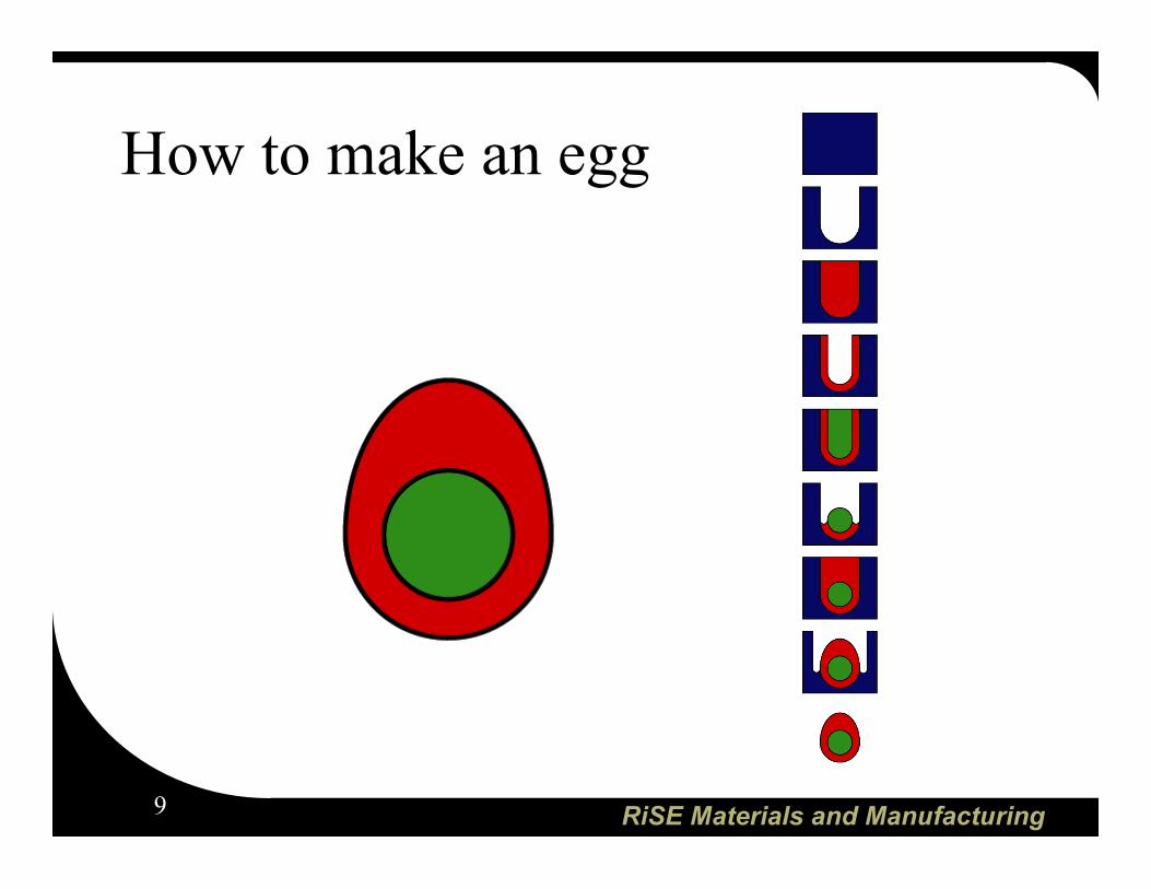
Decompose Deposit Machine
Decompose Deposit MachineInput
RiSE Materials and Manufacturing9
How to make an egg

RiSE Materials and Manufacturing10
Cool SDM stuff to date
10 mm10 mm
Embedded componentsCham et al., 1999
Embedded sensorsWuensch., 2001
Multi-materials - Roger, 2000
Fiber-reinforcedjoints
Moto, 2001RiSE foot V4 (2-17-04)

RiSE Materials and Manufacturing11
Embedded sensor example:pressure sensor unit for pneumaticactuators
Screen shot from SDM CAD environment:several steps in the “building block”design/fabrication sequence for theembedded pressure sensor package
PC board CAD file forcommercial MEMS pressuretransducer & instrumentation
RiSE Materials and Manufacturing12
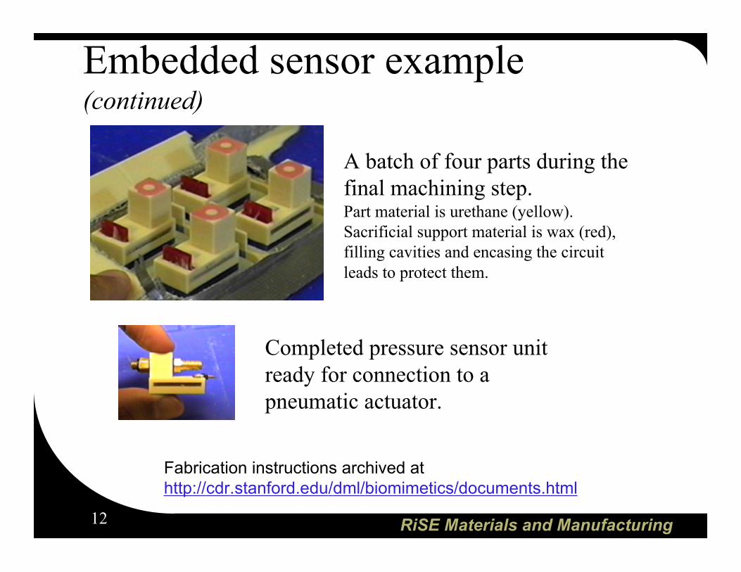
Embedded sensor example(continued)
Completed pressure sensor unitready for connection to apneumatic actuator.
A batch of four parts during thefinal machining step.Part material is urethane (yellow).Sacrificial support material is wax (red),filling cavities and encasing the circuitleads to protect them.
Fabrication instructions archived at http://cdr.stanford.edu/dml/biomimetics/documents.html

RiSE Materials and Manufacturing13
Embedded actuator example
Deposition: part and support materialsare cast in place, aftereach machining stage
Shaping: structures are machined a pallet on a CNC mill
RiSE Materials and Manufacturing14
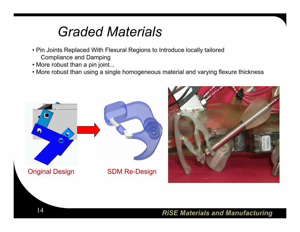
Original Design SDM Re-Design
• Pin Joints Replaced With Flexural Regions to Introduce locally tailored Compliance and Damping• More robust than a pin joint...• More robust than using a single homogeneous material and varying flexure thickness
Graded Materials
RiSE Materials and Manufacturing15
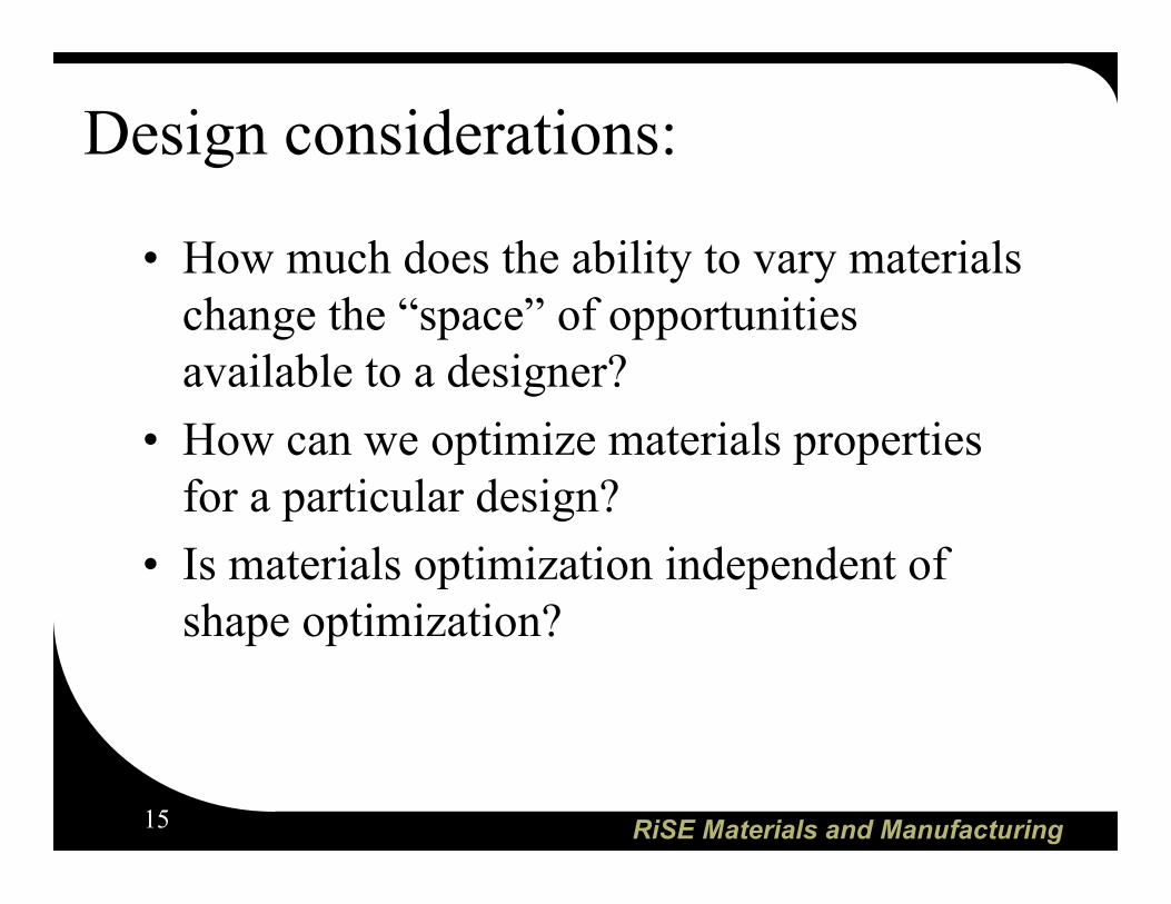
Design considerations:
• How much does the ability to vary materialschange the “space” of opportunitiesavailable to a designer?
• How can we optimize materials propertiesfor a particular design?
• Is materials optimization independent ofshape optimization?

RiSE Materials and Manufacturing16
Design synthesis: shape optimization
Shape optimizationexample:Find the minimum-weight shelfstructure, bounded by box B,that supports load W without failing.B
W
Space within B is divided into N cells, each of whichcan be filled or empty. Number of unique designs ≈ 2N
(Of course, most of the naive solutions will not befeasible. Still, the search space is large.)

RiSE Materials and Manufacturing17
Ability to vary material composition
Support structure
depositionheads
Deposition heads can becontrolled to depositvarying amounts of eachmaterial* as the part isbuilt. Total materialcomposition variesthroughout the part.
Volume fractions always add to unity*
*void, or empty space, is treated as a special case of material
RiSE Materials and Manufacturing18
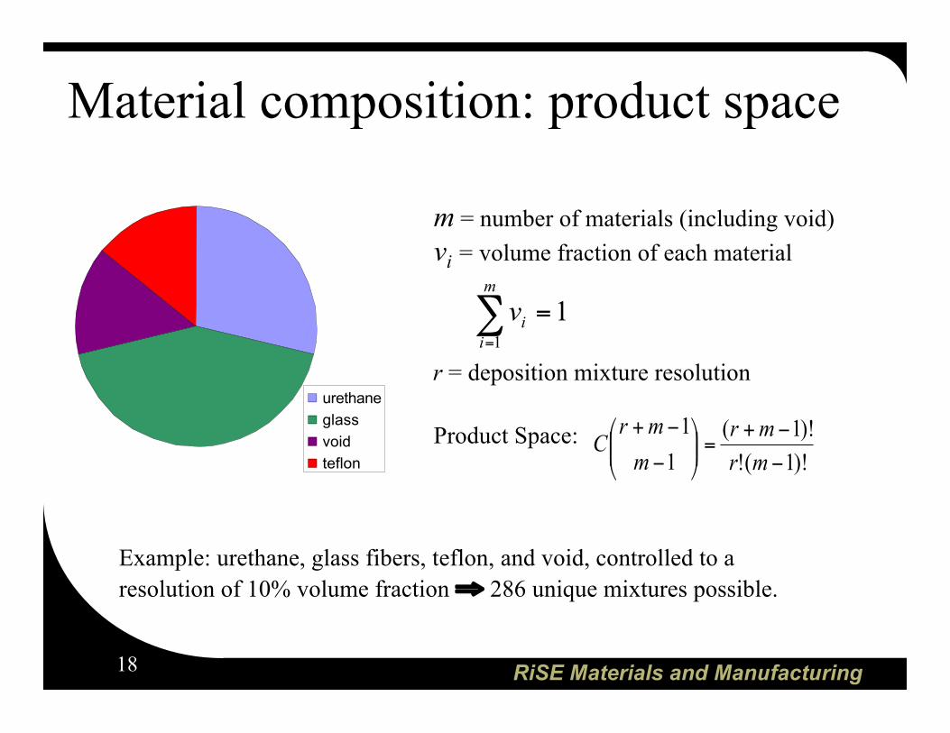
Material composition: product space
Product Space:)!1(!
)!1(
1
1
!
!+=""
#
$%%&
'
!
!+
mr
mr
m
mrC
urethane
glass
void
teflon
m = number of materials (including void)vi = volume fraction of each material
r = deposition mixture resolution
1
1
=!=
m
i
iv
Example: urethane, glass fibers, teflon, and void, controlled to aresolution of 10% volume fraction ⇒ 286 unique mixtures possible.

RiSE Materials and Manufacturing19
Design space dimensions with arbitrarygeometry and heterogeneous materials:
(E3 × Rm)Shape + material optimization:Assume m possible materials,(including void) with a mixtureresolution of r.B
W
Space within B is discretized into N cells, each of whichcan be filled with a unique mixture of materials.
Number of unique designs ≈
Example: 10×10×10 cells, 4 materials, 10% mixture resolution⇒ 2861000 designs!
(r + m -1)!
r!(m - 1)!
N

RiSE Materials and Manufacturing20
Materials selection and optimizationexample [M. Ashby book]
Consider a flexure orelastic hinge (as in the legsof the Sprawlita robots)
What is the best materialfor the hinge region?
(See Ashby chart on E versus σfail)
Goal: find material that • is strong enough• allows us to minimize Rbend
Ashby, M.F., "Materials Selection in Mechanical Design," 2nd. edition, Butterworth Heinmann, Oxford, 1999.

21

RiSE Materials and Manufacturing22
Graded Materials• Graded interface increases surface area, resulting in increased bonding• Function needs to be applied To discretize the graded regions based upon a
specified tolerance parameter

RiSE Materials and Manufacturing23
Design Constraints• 2.5D/3D
• Tool Size Constraints
• Ordering
• Materials
Example of 2.5D/3D GeometryWhite Regions (Soft Material) in 2.5DClear Regions (Hard Material) in 3D
Ordering defined By urethanehardness. Processed to minimize
machining on soft surfaces

RiSE Materials and Manufacturing24
1 12
43
Support MaterialHard Part MaterialSoft Part Material
1 3
2
4 1
3
2
4
Adjacency Graph Precedence GraphCompliant Joint
Functional considerations:fatigue life determines plan
Soft material should becast into surrounding material

RiSE Materials and Manufacturing25
Refined compliant joint
1 12
43
Support MaterialHard Part MaterialSoft Part Material
1 3
2
4 1
3
2
4
Adjacency Graph Precedence Graph
55
5
5
Functional considerations:fatigue life determines plan
Planing producessmooth surface
Why must 4 precede 5?

RiSE Materials and Manufacturing26
Psuedo-boundary formation
RiSE Materials and Manufacturing27
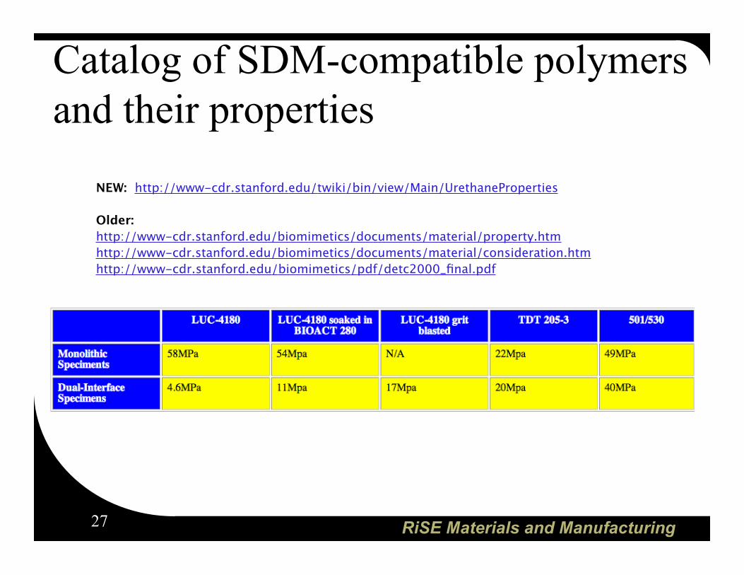
Catalog of SDM-compatible polymersand their properties
NEW: http://www-cdr.stanford.edu/twiki/bin/view/Main/UrethaneProperties
Older:http://www-cdr.stanford.edu/biomimetics/documents/material/property.htmhttp://www-cdr.stanford.edu/biomimetics/documents/material/consideration.htmhttp://www-cdr.stanford.edu/biomimetics/pdf/detc2000_final.pdf