scope & specifications of concrete water tankcwd.com.ph/bid_post/scope and specifications... ·...
TRANSCRIPT

REF: LWUA STANDARD SPECIFICATIONS; DPWH (BLUE BOOK) 2004, BUILDING CODE PHILIPPINES; theconstructor.org D:\BAC FILES.ronnie.2017 onwards\2019 PROJECTS\CWD 28.2019.Water Tank.Bidding\CONCRETE TANK with addendum.docx
SCOPE & SPECIFICATIONS
OF CONCRETE WATER TANK (CALAMBA WATER DISTRICT- PDD)

i REF: LWUA STANDARD SPECIFICATIONS; DPWH (BLUE BOOK) 2004, BUILDING CODE PHILIPPINES; theconstructor.org D:\BAC FILES.ronnie.2017 onwards\2019 PROJECTS\CWD 28.2019.Water Tank.Bidding\CONCRETE TANK with addendum.docx
September 2018
Prepared by:
Engr. Anna Katherine A. De Torres Engineer A, CWD-PDD
Checked by:
Engr. Kristine R. Cervancia Senior Engineer, CWD-EPDD
Recommending Approval by:
Engr. Ranely S. Cartago Engineering Department Manager, CWD-EPDD
Approved by:
Engr. Restituto B. Sumanga, Sr. General Manger, CWD

ii REF: LWUA STANDARD SPECIFICATIONS; DPWH (BLUE BOOK) 2004, BUILDING CODE PHILIPPINES; theconstructor.org D:\BAC FILES.ronnie.2017 onwards\2019 PROJECTS\CWD 28.2019.Water Tank.Bidding\CONCRETE TANK with addendum.docx
TABLE OF CONTENTS
I. SPECIFICATIONS & SCOPE OF WORKS
A. EARTHWORKS ....................................................................................................................................... 1
A.1. Excavation ....................................................................................................................................... 1
A.2. Backfill/ Restoration ........................................................................................................................ 2
B. FORMWORKS ........................................................................................................................................ 2
C. CONCRETING WORKS ............................................................................................................................ 2
C.1. Placement of Concrete .................................................................................................................... 2
C.2. Curing .............................................................................................................................................. 2
D. REBAR WORKS ...................................................................................................................................... 2
C.1. Placing Reinforcement .................................................................................................................... 2
C.2. Offsets and Splices in Reinforcement .............................................................................................. 3
E. PAINTING WORKS .................................................................................................................................. 3
F. MISCELLANEOUS WORKS ...................................................................................................................... 3
G. PIPE LAYING .......................................................................................................................................... 3
C.1. Installation ...................................................................................................................................... 3
C.2. Laying of Pipes into Trench ............................................................................................................. 3
3. Connections to Existing Water Mains ................................................................................................. 4
4. Thrust Blocking ................................................................................................................................... 4
H. TESTING & DISINFECTION OF CONCRETE RESERVOIR AND APPURTENANCES ................................... 4
1. Cleaning ............................................................................................................................................. 4
2. Chlorination ........................................................................................................................................ 4
3. Retention Period ................................................................................................................................ 4
4. Final Filling of Reservoir ..................................................................................................................... 5
5. Leakage Allowance ............................................................................................................................. 5
I. WATERPROOFING ........................................................................................................................... 5

iii REF: LWUA STANDARD SPECIFICATIONS; DPWH (BLUE BOOK) 2004, BUILDING CODE PHILIPPINES; theconstructor.org D:\BAC FILES.ronnie.2017 onwards\2019 PROJECTS\CWD 28.2019.Water Tank.Bidding\CONCRETE TANK with addendum.docx
II. MATERIALS
A. CONCRETE ............................................................................................................................................. 6
B. METAL REINFORCEMENTS .................................................................................................................... 6
C. FORMWORKS ........................................................................................................................................ 6
D. PIPE LAYING .......................................................................................................................................... 7
E. PAINTING ............................................................................................................................................... 9
F. MISCELLANEOUS METALWORK ............................................................................................................. 9
G. WATERPROOFING ............................................................................................................................... 10
H. PERMITS …………………………………………………………………………………………………………………………………..….… 10

1 REF: LWUA STANDARD SPECIFICATIONS; DPWH (BLUE BOOK) 2004, BUILDING CODE PHILIPPINES; theconstructor.org D:\BAC FILES.ronnie.2017 onwards\2019 PROJECTS\CWD 28.2019.Water Tank.Bidding\CONCRETE TANK with addendum.docx
SPECIFICATIONS & SCOPE OF WORKS
A. EARTHWORKS
1. Excavation
Except when specifically provided to the contrary, excavation shall include the removal of materials of
whatever natured encountered, including all obstructions of any nature that would interfere with the
proper execution and completion of the work. The removal of said materials shall conform to the lines
and grades shown or ordered. Unless otherwise provided, the entire construction site shall be stripped
of all vegetation and debris, and such materials shall be removed from the site prior to performing any
excavation or placing any fill. The contractor shall furnish, place, and maintain all supports and shoring
that may be required for the sides of the excavations, and all pumping, ditching, or other approved
measures for the removal or exclusion of water, including taking care of storm water and waste water
reaching the site of the work from any source so as to prevent damage to the work or adjoining
property.
The walls and faces of all excavations in which workers are exposed to danger from unstable ground
shall be guarded against by a shoring system, sloping of the excavation, or some other acceptable
method. The contractor shall furnish, install, and maintain such sheeting, bracing, etc., as may be
necessary to protect the workers and to prevent any movement of earth which could injure or delay the
work or endanger adjacent structures. In excavations which workers may be required to enter,
excavated or other materials shall be effectively stored and retained at least 600mm or more from the
edge of the excavation. All excavation and trenching operations shall conform to any and all national,
provincial and local safety requirements.
Excavation beneath proposed structures. Except where otherwise specified for a particular structure or
ordered by the engineer, excavation shall be carried to the grade of the bottom of the footing or slab.
Where shown and ordered, areas beneath proposed structures shall be over-excavated. When such
over-excavation is shown on the drawings, both over-excavation and subsequent backfill to the required
grade shall be performed by the contractor at his own expense. When such over-excavation is not
shown but is ordered by the engineer, such over-excavation and any resulting backfill will be paid for
under a separate unit price bid item if such bid item has been established; otherwise payment will be
made in accordance with negotiated prices. After the required excavation or over-excavation has been
completed, the exposed surface shall be scarified to a depth of 150 mm (6-in.) Brought to optimum
moisture content, and rolled with heavy compaction equipment to ninety-five percent (95%) of
maximum density.
Excavation beneath areas to be paved. Excavation under areas to be paved shall extend to the bottom
of the aggregate base, if such base is called for; otherwise it shall extend to the bottom of paving. After
the required excavation has been completed, the exposed surface shall be scarified, brought to
optimum moisture content, and rolled with heavy compaction equipment to ninety percent (90%) of
maximum.

2 REF: LWUA STANDARD SPECIFICATIONS; DPWH (BLUE BOOK) 2004, BUILDING CODE PHILIPPINES; theconstructor.org D:\BAC FILES.ronnie.2017 onwards\2019 PROJECTS\CWD 28.2019.Water Tank.Bidding\CONCRETE TANK with addendum.docx
2. Backfill/ Restoration
Provide clay type backfilling materials. Compact the materials in a manner approved by the engineer or
in compliance to 95% compaction California Bearing Ratio (CBR). Use necessary equipment during
compaction.
Compaction tests- all field density tests shall be performed in accordance with the test procedure
specified in “method of test for density of soil in place by the sand cone method” (ASTM d1556).
Barricades and warning lights satisfactory to the engineer shall be provided and maintain for all in which
case of heavy steel plates, adequately braced bridges or other type of crossing capable of supporting
vehicular traffic shall be furnished.
B. FORMWORKS
Forms for exposed concrete structure shall be of steel or new plywood panels. All other forms shall be of steel
panels, plywood or surfaced lumber. Exposed vertical corners of all concrete structures shall be given a 19mm
(3/4in) chamfer. Forms shall not be removed until permission to do so has been received from the engineer or until
the concrete has obtained eighty (80%) of its 28-day strength.
C. CONCRETING WORKS
1. Placement of concrete
As concrete is placed in forms or in excavations, it shall be thoroughly settled and compacted throughout
the entire depth of the layer which is being consolidated, into a dense homogeneous mass. Except in
special case where their use is deemed impractical by the engineer, the contractor shall use high-speed
internal vibrators of an approved immersion type.
2. Curing
All structural concrete shall be cured by being kept moist for fourteen (14) days after placing, or at the
option of the contractor, may be cured by use of a curing compound approved by the engineer.
Encasement concrete and thrust blocks shall be covered with earth not prior to four (4) hours but not later
than twenty-four (24) hours after placing.
D. REBAR WORKS
1. Placing Reinforcement
All reinforcement shall be placed in accordance with the plans furnished by the Engineer. In case any
doubt or ambiguity in placing of steel, the Contractor shall consult with the Engineer whose decision shall
be final in such cases. All loose rust or scale, all adhering materials, and all oil or other materials which
tend to destroy bond between the concrete and the reinforcement shall be removed before placing the
steel and before concreting begins. Metal reinforcement shall be accurately placed and adequately

3 REF: LWUA STANDARD SPECIFICATIONS; DPWH (BLUE BOOK) 2004, BUILDING CODE PHILIPPINES; theconstructor.org D:\BAC FILES.ronnie.2017 onwards\2019 PROJECTS\CWD 28.2019.Water Tank.Bidding\CONCRETE TANK with addendum.docx
secured by using annealed iron wire ties or suitable clips at intersections and shall be supported by
concrete or metal supports, spacers or metal hangers.
All bars shall be bent cold. Reinforcement steel shall not be straightened or rebent in a manner that will
injure the material. Bars with kinks or bends not shown on the drawings shall not be used. Heating of the
reinforcement will be permitted only when approved by the Engineer.
2. Offsets and Splices in Reinforcement
In slabs, beams, and girders, splices of reinforcement at points of maximum stress shall be generally
avoided, and may be allowed only upon written approval of splice details by the Engineer. Splices shall
provide sufficient lap to transfer stress between bars by bonding shear or by butt welding to develop in
tension at least 125 percent of the specified yield strength of the reinforcing bar. Splices in adjacent bars
shall be generally staggered.
E. PAINTING WORKS
All painting activities shall be in accordance to standards. Colors shall be coordinated to owner prior to
application. Paints shall be latex paints for concrete, quick dry enamel for wood and epoxy paint for steel. Apply
patching compound and glazing putty to all uneven surfaces of concrete and wood respectively. Surfaces to be
applied shall be approved by the engineer prior to application of first coating and final coating, provide barricades
or signage to protect wet paints. Follow manufacturer’s specifications.
F. MISCELLANEOUS METALWORK
The Contractor shall furnish, fabricate and install all the miscellaneous metalwork as specified and shown.
Miscellaneous metalwork is defined as all items required to be fabricated from structural steel shapes, plates, bars
and their products. All structural steel
G. PIPE LAYING
1. Installation
Install pipes, specials, fittings, closure pieces, valves, supports, bolts, nuts, gaskets, jointing materials and all other appurtenances as shown and as required to provide a complete and workable installation. Where pipe supports details are shown, the supports shall conform thereto and shall be placed as indicated; provided, that the support for all exposed piping shall be complete and adequate regardless of whether or not supporting devices are specifically shown. At all times when the work of installing pipes is not in progress, all openings into the pipe and the ends of the pipe in trenches shall be kept tightly closed to permit entrance of animals and foreign materials.
2. Laying of Pipes into Trench
Trenches shall be in a reasonably dry condition when the pipe is laid. The pipe sections shall be laid to the line and grade when shown and they shall be closely jointed to form a smooth flow line. Immediately
4 REF: LWUA STANDARD SPECIFICATIONS; DPWH (BLUE BOOK) 2004, BUILDING CODE PHILIPPINES; theconstructor.org D:\BAC FILES.ronnie.2017 onwards\2019 PROJECTS\CWD 28.2019.Water Tank.Bidding\CONCRETE TANK with addendum.docx
before placing each section of pipe in final position for jointing, the bedding for the pipe shall be checked for firmness and uniformity of surface.
3. Connections to Existing Water Mains
Preassemble fittings, valves etc., as far as possible and have all necessary tools and equipment on-site before shutting off the existing main. Pour concrete thrust blocks, if required, to the new line and allow curing for at least eight days before the pipe is put under pressure.
4. Thrust Blocking
Concrete thrust blocks, anchor blocks or welded joints shall be provided at all junctions, changes in directions exceeding 11½º or where otherwise shown. Concrete should have a compressive strength of at least 140 kg/cm2, 28 days after pouring. This can be accomplished by mixing the following proportions:
One part Portland cement
2½ parts clean sand (do not use beach sand)
Five parts crushed stone (1 – 3 cm)
Enough water to make a workable mix
H. TESTING & DISINFECTION OF CONCRETE RESERVOIR AND APPURTENANCES
1. Cleaning
Prior to disinfecting, the reservoir shall be thoroughly cleaned by hosing down with a high pressure hose
and nozzle of sufficient size to deliver minimum flow of 3.15 lps (50gpm).
2. Chlorination
A strong chlorine solution (200mg per liter) shall be sprayed on all interior surface of the reservoir.
Following this, the reservoir shall be partially filled with water to a minimum depth of approximately 30cm
(1ft.). During the filling operation a chlorine water mixture shall be injected by means of a solution feed
chlorinating device. The dosage applied to the water shall be sufficient to give a chlorine residual of at
least 50mg per liter upon completion of the partial filling operation. Precaution shall be taken to prevent
the strong chlorine solution from flowing back into the lines supplying the water. After the partial filling
has been completed, sufficient water shall be drained from the lower ends of the appurtenant piping to
insure filling the lines with the heavily chlorinated water.
3. Retention Period
Chlorinated water shall be retained in the reservoir and in the appurtenant piping long enough to destroy
all non-spore forming bacteria and, in any event for at least twenty four (24) hours. After the chlorine-
treated water has been retained for the required time, the chlorine residual in the reservoir and in the
lines shall be at least 25mg per liter. All valves shall be operated while the lines are filled with the heavily
chlorinated water.

5 REF: LWUA STANDARD SPECIFICATIONS; DPWH (BLUE BOOK) 2004, BUILDING CODE PHILIPPINES; theconstructor.org D:\BAC FILES.ronnie.2017 onwards\2019 PROJECTS\CWD 28.2019.Water Tank.Bidding\CONCRETE TANK with addendum.docx
4. Final Filling of Reservoir
After the chlorine residual has been checked in accordance with Subsection (d), the water level in the
reservoir shall be raised uniformly by approximately one foot below the overflow level by the addition of
potable water. Before final filling is commenced, the quantity of heavily chlorinated water remaining in the
reservoir after filling the piping shall be sufficient when the water level is raised to its final elevation to
produce a chlorine residual of between 1 mg per liter and 2 mg per liter. After the reservoir has been
filled, the strength of the chlorinated water in the reservoir shall be determined by the Engineer. If the
chlorine residual is less than 1 mg per liter, an additional dosage shall be applied to the water in the
reservoir, the reservoir shall be partially emptied and additional potable water added. In no case shall
water be released through the drain lines prior to the expiration of the required retention period.
5. Leakage Allowance
After the reservoir has been filled continuously for a period of thirty days, if leakage is such that the water
surface drops more than 5.1 cm (2 in) in a 30 day period, the Contractor shall empty the reservoir to
permit close examination for evidence of any cracking or other conditions that might be responsible for
the leakage. Any cracks shall be “vee’d” and sealed with rubber sealant in accordance with Section 21.
13 (b). Any evidence of leakage through joints shall be repaired to the satisfaction of the Engineer.
Following these operations, the Contractor shall again sterilize the reservoir in accordance with this
section, exclusive of the spraying operation.
I. WATERPROOFING
1. In concrete: The method of application of admixture and other details is based on the manufacturer’s
specification.
2. In plaster: The concrete surface, to be plastered, is cleaned thoroughly and kept wetted for 24 hours.
The plaster in cement sand mortar mixed in proportion varying from 1:1 to 1:4 by volume along with
the waterproofing admixture and laid in appropriate thickness and in layers not exceeding 15mm
layer or as per manufacturer’s specification. The additive. On completion, the plastered surface shall
be cured continuously for a minimum period of 14 days like concrete.

6 REF: LWUA STANDARD SPECIFICATIONS; DPWH (BLUE BOOK) 2004, BUILDING CODE PHILIPPINES; theconstructor.org D:\BAC FILES.ronnie.2017 onwards\2019 PROJECTS\CWD 28.2019.Water Tank.Bidding\CONCRETE TANK with addendum.docx
MATERIALS SPECIFICATIONS
A. CONCRETE
Cement and sand shall be stored in such manner as to prevent deterioration or intrusion of foreign matter.
Any materials that has deterioration or has been contaminated shall not be used for mortar. Slump test shall
be conducted by the contractor under the supervision of the engineer. It should not exceed the maximum
slump of 75mm (3in.) for footing and slab and 100mm (4in.) for all other concrete.
Portland cement: cement shall conform to the standard specifications for ready mixed concrete, ASTM-
C 94 or on the specification for portland cement, ASTM C 150 or PNS 07. An air-entraining admixture,
conforming to astm c-260, shall be added to type i, type ii or type iii portland cement. Mixture shall be 1:1-
1/2 : 3 or as suggested by the engineer depending on type of cement. Use 40 kg bag of cement.
Aggregates: all aggregates used for concreting shall conform to ASTM C 33 or PNS 18 and shall be
checked daily for any variances in moisture current. Said variances shall be corrected and/or taken into
consideration for each batch.
Coarse aggregates: shall be uniformly and evenly graded for each application in accordance ACI
Standard 318. Unless otherwise approved, aggregate shall be sound, crushed, angular grantic stone.
Smooth or rounded stone (river rock) shall not be acceptable.
Fine aggregates: shall consist of natural sand, manufactured sand or a combination thereof.
Water: water used in mixing concrete shall be clean and free from injurious amounts of oils, acids, alkalis,
slats, organic materials, or other substances that may be deleterious to concrete or reinforcement.
B. METAL REINFORCEMENTS
Reinforcing bars may be galvanized or epoxy coated in accordance with specification for zinc-coated
(galvanized) steel bars for concrete reinforcement, ASTM a 767 or specification for epoxy-coated reinforcing
steel bars ASTM a 775. Use minimum fy = 276 Mpa (Grade 40).
C. FORMWORKS
1. Use ordinary plywood with dimension 4’ x 8’ x 1/2 “dried as delivered.
2. Use coco lumber size 2” x 2” x 12’ and 2” x 4” x 12’ free from deformation and pests that could destroy
its quality

7 REF: LWUA STANDARD SPECIFICATIONS; DPWH (BLUE BOOK) 2004, BUILDING CODE PHILIPPINES; theconstructor.org D:\BAC FILES.ronnie.2017 onwards\2019 PROJECTS\CWD 28.2019.Water Tank.Bidding\CONCRETE TANK with addendum.docx
D. PIPE LAYING
1. Galvanized Iron (GI)
a. Pipes shall conform to the requirements of the ASTM A53/A53M (Standard Specification for Pipe, Steel, Black and Hot-Dipped, Zinc-Coated, Welded and Seamless) or the latest revision or its equivalent and shall be Schedule 40.
b. Pipe fittings shall conform to the requirements of ASME/ANSI B16.3 (Malleable Iron Threaded Fittings Class 150 and 300) and shall be Class 150.
c. The pipe shall be practically straight and both ends of the pipe shall be at right angle to the axis of the pipe. The inside and outside surfaces of the pipe shall be free from injurious defects. Unless otherwise specified, the length of the pipe shall be 6 meters. The tolerance shall be plus 6 meters without negative tolerance. Pipes shall be clearly marked with Trademark, Nominal Size, Length and Class of Pipe.
d. The pipe and fitting threads shall be made according to “American Standard Pipe Taper Thread (NPT) with taper angle equal to 1˚47’.
e. Pipes and fittings shall be coated with zinc, both inside and outside surfaces, in accordance to ASTM A153/A153M–05 (Standard Specification for Zinc Coating (Hot–Dip) on Iron and Steel Hardware)
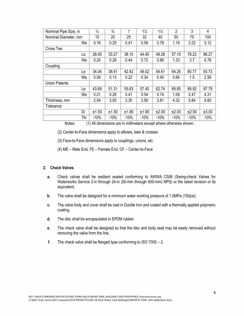
Table 1. GI Pipe and Fitting Dimensions
Nominal Pipe Size, in ½ ¾ 1 1¼ 1½ 2 3 4
Nominal Diameter, mm 15 20 25 32 40 50 75 100
Pipes
Outside Diameter, mm 21.3 26.7 33.4 42.2 48.3 60.3 88.9 114.3
Wall Thickness, mm 2.8 2.9 3.4 3.6 3.7 3.9 5.49 6.02
Tolerance
out
sid
e
dia
me
ter,
m
m
±0.39
7
±0.39
7
±0.39
7
±0.39
7
±0.39
7
±1% ±1% ±1%
wal
l
thi
ck
ne
ss
-
12.5%
-
12.5%
-
12.5%
-
12.5%
-
12.5%
-
12.5%
-
12.5%
-
12.5% Weight per meter, kg 1.27-
1.34
1.68-
1.78
2.50-
2.62
3.38-
3.55
3.75-
4.23
5.00-
5.43
10.3-
11.3
14.5-
16.1 Fittings
90º Elbow
Le
ngt
h
28.45 33.27 38.10 44.45 46.74 57.15 78.23 96.27
We
igh
t,
kg
0.11 0.18 0.29 0.43 0.56 0.79 2.34 4
45º Elbow
Le
ngt
h
22.35 24.89 28.45 32.77 36.32 42.67 55.12 66.29
We
igh
t,
kg
0.07 0.10 0.15 0.38 0.52 0.77 2.11 3.46
St. Elbow
Le
ngt
h,
ME
40.89 48.01 54.10 61.98 67.82 83.06 114.55 114.27
Le
ngt
h,
FE
28.45 33.02 38.10 44.45 49.28 57.15 78.23 96.27
We
igh
t,
kg
0.11 0.18 0.29 0.49 0.66 1.06 2.99 4.94
Tee
Le
ngt
h
28.45 33.27 38.10 44.45 49.28 57.15 78.23 96.27
8 REF: LWUA STANDARD SPECIFICATIONS; DPWH (BLUE BOOK) 2004, BUILDING CODE PHILIPPINES; theconstructor.org D:\BAC FILES.ronnie.2017 onwards\2019 PROJECTS\CWD 28.2019.Water Tank.Bidding\CONCRETE TANK with addendum.docx
Nominal Pipe Size, in ½ ¾ 1 1¼ 1½ 2 3 4
Nominal Diameter, mm 15 20 25 32 40 50 75 100
We
igh
t,
kg
0.16 0.25 0.41 0.59 0.78 1.19 3.22 5.12
Cross Tee
Le
ngt
h
28.45 33.27 38.10 44.45 49.28 57.15 78.23 96.27
We
igh
t,
kg
0.20 0.29 0.44 0.72 0.86 1.33 3.7 6.76
Coupling
Le
ngt
h
34.04 38.61 42.42 49.02 54.61 64.26 80.77 93.73
We
igh
t,
kg
0.09 0.13 0.22 0.34 0.45 0.66 1.5 2.56
Union Patente
Le
ngt
h
43.69 51.31 55.63 57.40 62.74 69.85 89.92 97.79
We
igh
t,
kg
0.21 0.26 0.41 0.54 0.74 1.09 2.47 4.31
Thickness, mm 2.54 3.05 3.30 3.56 3.81 4.32 5.84 6.60
Tolerance
Di
me
nsi
on,
CF
,
m
m
±1.50 ±1.50 ±1.80 ±1.80 ±2.00 ±2.00 ±2.50 ±3.00
Thi
ck
ne
ss
-10% -10% -10% -10% -10% -10% -10% -10%
Notes: (1) All dimensions are in millimeters except where otherwise shown.
(2) Center-to-Face dimensions apply to elbows, tees & crosses
(3) Face-to-Face dimensions apply to couplings, unions, etc.
(4) ME – Male End, FE – Female End, CF – Center-to-Face
2. Check Valves
a. Check valves shall be resilient seated conforming to AWWA C508 (Swing-check Valves for Waterworks Service 2-in through 24-in (50-mm through 600-mm) NPS) or the latest revision or its equivalent.
b. The valve shall be designed for a minimum water working pressure of 1.0MPa (150psi).
c. The valve body and cover shall be cast in Ductile Iron and coated with a thermally applied polymeric coating.
d. The disc shall be encapsulated in EPDM rubber.
e. The check valve shall be designed so that the disc and body seat may be easily removed without removing the valve from the line.
f. The check valve shall be flanged type conforming to ISO 7005 – 2.

9 REF: LWUA STANDARD SPECIFICATIONS; DPWH (BLUE BOOK) 2004, BUILDING CODE PHILIPPINES; theconstructor.org D:\BAC FILES.ronnie.2017 onwards\2019 PROJECTS\CWD 28.2019.Water Tank.Bidding\CONCRETE TANK with addendum.docx
3. Gate Valve (Brass)
a. Brass valves shall be full port, screwed-in bonnet and non-rising stem.
b. The valve body, bonnet and solid wedge disc shall be brass conforming to ASTM B584 Alloy C84400-1996 or the latest revision or its equivalent. The minimum pressure rating shall be 125psi saturated steam pressure and 200psi non-shock water, oil or gas.
c. The valve shall be threaded end conforming to ASME B1.20.1 (NPT)
Table 2. Brass Gate Valve Dimensions
Nominal Pipe Size, in ½ ¾ 1 1¼ 1 ½ 2
Nominal Diameter, mm 15 20 25 32 40 50
Length, mm 35 – 43 39 – 45 43 – 54 48 – 61 54 – 63 58 – 72
Height, mm 71 – 72 77 – 84 88 – 98 103 –
116
114 –
125
134 –
153 Handwheel Diameter, mm 54 – 55 54 – 55 60 – 61 72 – 77 72 – 77 80 – 83
E. PAINTING
1. The Contractor may substitute other paint materials for those specified in Section 27.13 provided he first
receives written approval from the Engineer stating that said proposed substituted materials are equal to
that specified and are approved for use. A complete proposed for use shall be submitted for Engineer’s
approval.
2. Colors and Samples
All finish colors shall be as selected by the Owner. In multicoated work using color pigmented paints,
each coat shall have sufficient variation of color to easily distinguish it from preceding coat; Using
specified or approved materials, three (3) sample panels of each finish, including all costs thereof shall
be prepared and submitted for the Owner’s approval. Completed work shall match approved colors and
samples.
3. Interior Paints. Reservoir should be painted by at least 3 coatings (1st coat: Redoxide, 2nd coat: Epoxy
Gray, 3rd coat: Epoxy White (Foodgrade).
Exterior Paints. Reservoir should be painted by at least 3 coatings (1st coat: Redoxide, 2nd coat: Epoxy
Gray, 3rd coat: Epoxy White (Foodgrade).
F. MISCELLANEOUS METALWORK
1. Galvanizing
All structural steel plates, shapes, bars and fabricated assemblies required to be galvanized shall, after the
steel has been thoroughly cleaned of rust and scale, be galvanized in accordance with the “Specification for
Zinc (Hot Galvanized) Coatings (ASTM A123). Bolts, anchor bolts, nuts and similar threaded fasteners, after

10 REF: LWUA STANDARD SPECIFICATIONS; DPWH (BLUE BOOK) 2004, BUILDING CODE PHILIPPINES; theconstructor.org D:\BAC FILES.ronnie.2017 onwards\2019 PROJECTS\CWD 28.2019.Water Tank.Bidding\CONCRETE TANK with addendum.docx
being properly cleaned, shall be galvanized in accordance with the “Specification for Zinc Coating (Hot-Dip)
on Iron and Steel hardware” (ASTM A153).
2. Welding
All welding shall be by the shielded arc method and shall conform to the “AWS Code for Arc and Gas Welding
in Building Construction”. Qualification of weld shall be in accordance with the “Specifications for Standard
Qualification Procedure” of AWS.
3. Ladders
All ladders shall be fabricated of carbon steel and galvanized after fabrication or as indicated in drawings.
4. Steel Pipe Handrails
Steel pipe handrails shall be standard 38mm (1-1/2 in) in diameter steel pipe made up by welding. Railing
shall be shop-fabricated into easily handled, Field welding of pipe handrail joints will be permitted only if
approved by the Engineer, and then only in accordance with his instructions.
G. WATERPROOFING
1. Cement based waterproofing powder mix shall be cement-base, aggregate type, heavy duty, water-proof
coating for reinforced concrete surface and masonry exposed to water. The aggregates are graded and
sized so as to mesh perfectly and are selected for purity, hardness, strength and are non-metallic. When
mixed with other ingredients, the mix shall be a free flowing, water-proof coatings that possesses strength
durability and density.
2. Additive binders shall be of special formulation of acrylic polymers and modifiers in liquid form used as
additive with cement base powder mix that improves adhesion and mechanical properties.
3. Water shall be clean, clear and potable.
4. One (1) brand or type of waterproofing material shall be used on the project.
5. Waterproofing materials shall be restored in weather tight enclosure to avoid moisture damage and
absorption.
H. PERMITS
1. Building Permit and all supporting documents required shall be provided.