scope of work & technical specifications …gailtenders.in/writereaddata/tender/specs for plc...
TRANSCRIPT
DESIGN, SUPPLY, INSTALLATION, TESTING & COMMISSIONING OF GAS DETECTION SYSTEM AT GAIL
LPG RECOVERY PLANT, USAR Page | 1
SCOPE OF WORK & TECHNICAL SPECIFICATIONS
UPGRADATION OF GAS DETECTION SYSTEM AT LPG RECOVERY PLANT
GAIL USAR
DESIGN, SUPPLY, INSTALLATION, TESTING & COMMISSIONING OF GAS DETECTION SYSTEM AT GAIL
LPG RECOVERY PLANT, USAR Page | 2
TABLE OF CONTENTS 1. INTRODUCTION
2. EXISTING SYSTEM
3. PROPOSED SYSTEM DESCRIPTION 4. EXECUTION PHILOSOPHY
5. SCOPE OF WORK
6. FUNCTIONAL SPECIFICATIONS
ANNEXURE-I : DETAILS OF PLC, HMI AND ENGG. STATION, SENSORS, JBs, CABINET AND OPERATOR CONSOLE
ANNEXURE-II : INDICATIVE BILL OF MATERIAL
ANNEXURE-III : BIDDER’S COMPLIANCE

DESIGN, SUPPLY, INSTALLATION, TESTING & COMMISSIONING OF GAS DETECTION SYSTEM AT GAIL
LPG RECOVERY PLANT, USAR Page | 3
1. INTRODUCTION
DESIGN, SUPPLY, INSTALLATION, TESTING & COMMISSIONING OF GAS DETECTION SYSTEM AT GAIL
LPG RECOVERY PLANT, USAR Page | 4
GAIL (India) Limited is one of the leading PSE in the country and ranks among top ten companies of India. Gas processing, transportation and distribution form the bulk of GAIL’s business followed by LPG and polymer production. This requirement is for the LPG Recovery plant of GAIL at USAR, Alibag, Maharashtra, India. GAIL (India) Ltd., USAR is in its continuous pursuit for safety in its plants intends to augment the existing Hydrocarbon Gas Detection System by a suitable Gas Detection System at its USAR Complex, as the existing system is very old & not getting spares & service supports from the OEM. The existing systems are covering the following areas: a) Mounded Storage Area b) Gas Compressor Unit e) LPG Plant area The GAIL, USAR complex is situated off the Alibag-Roha Road at USAR and is about 120 KM from the Capital city of Mumbai in Maharashtra State, India. It is connected from Mumbai city by road and by sea.
1. Plant Area Classification: NEC CLASS 1 DIVISION II GROUP A, B, C, D

DESIGN, SUPPLY, INSTALLATION, TESTING & COMMISSIONING OF GAS DETECTION SYSTEM AT GAIL
LPG RECOVERY PLANT, USAR Page | 5
2. EXISTING SYSTEM

DESIGN, SUPPLY, INSTALLATION, TESTING & COMMISSIONING OF GAS DETECTION SYSTEM AT GAIL
LPG RECOVERY PLANT, USAR Page | 6
2.1 EXISTING SYSTEM The existing Gas detection panel in this control room is proposed for replacement along with sensor at Field. However the existing cable (1 TRAID x 1.5 sqmm) shall be retained. Model of LEL card: DI-11, Sensor P/N: DI 5/6 Each sensor is connected to individual control module card inside the panel kept in the control room. The LEL card displays gas presence in %. It has High and High–High alarm by means of Red LED, Ready indicator by means of Green LED, Fault indicator by means of Yellow LED. The panel is equipped with hooter, acknowledgment and reset pushbuttons. The LEL sensors are three wired fitted on small field junction box. The individual sensor junction box is mounted on fixed support. All individual sensors are connected to main field junction box by separate cable and ultimately connected to control room through multi pair cable. Alarm 2 Outputs from each channel (60 nos) are also shared with a MIMIC panel for visual indication of alarms in field.

DESIGN, SUPPLY, INSTALLATION, TESTING & COMMISSIONING OF GAS DETECTION SYSTEM AT GAIL
LPG RECOVERY PLANT, USAR Page | 7
3. PROPOSED SYSTEM

DESIGN, SUPPLY, INSTALLATION, TESTING & COMMISSIONING OF GAS DETECTION SYSTEM AT GAIL
LPG RECOVERY PLANT, USAR Page | 8
PROPOSED GAS DETECTION SYSTEM DESCRIPTION
3.1 GAS DETECTION , MONITORING AND CONTROL SYSTEM GAIL, USAR intends to install independent Gas (HC) detection systems. The system shall be PLC based and the detailed Functional specification of PLC is attached. The individual detectors shall be connected to respective redundant I/O modules. The bidders are advised to visit the plant before the bid submission to ascertain the requirement of cables and other hardware for completing the Installation & Commissioning of the new systems on a turn-key basis.
Triad Cables from Control Room to each detector already exist and same is to be utilized for new system.
¾ inch NPT (M) Cable Glands also exist in the field, and same can also be utilized if compatible with Bidders System ( Bidder to consider supply of cable glands in their scope if ¾ inch NPT Cable Gland is not suitable for their system)
3.2 LPG CONTROL ROOM
Gas monitoring panel(s) catering to 60 IR type gas detectors shall be installed in place of existing old system in Control Room. The system shall be connected to one PC based HMI/operator console, one color printer and one Engg. Station (Laptop). Dry contacts of group alarms corresponding to different areas are to be made available in the panel.
3.3 LIST OF I/O’s
Analog Inputs (4 to 20 mA) - 60 No’s
Analog Outputs - Nil
Digital Inputs - Nil
Digital Outputs - 64 No’s ( Alarm 2 Outputs of each
Channel will be connected to drive MIMIC
Panel)
Installed Spares - 20% additional Spare capacity for all I/O’s to be considered as per Clause 6.10

DESIGN, SUPPLY, INSTALLATION, TESTING & COMMISSIONING OF GAS DETECTION SYSTEM AT GAIL
LPG RECOVERY PLANT, USAR Page | 9

DESIGN, SUPPLY, INSTALLATION, TESTING & COMMISSIONING OF GAS DETECTION SYSTEM AT GAIL
LPG RECOVERY PLANT, USAR Page | 10
4. EXECUTION PHILOSOPHY

DESIGN, SUPPLY, INSTALLATION, TESTING & COMMISSIONING OF GAS DETECTION SYSTEM AT GAIL
LPG RECOVERY PLANT, USAR Page | 11
4.0 EXECUTION PHILOSOPHY
PLC based independent Gas monitoring and control Systems to be installed at the Central Control Room. Gas monitoring panel to be designed for - catering to 60 IR type gas detectors installed in place of existing panels along with Engineering station, HMI mounted in Mettalic Console and printer. It is proposed to install 20 nos. of HC Gas Detectors for installation in Mounded Storage area of the USAR Complex in the Phase-1. The approximate distances between the field Junction boxes and the Control Room is approx. 1000 mtr. Gas detection system will not initiate any trip circuitry but would activate alarming devices such as hooters in the respective areas in case of Gas leak.
The indicative bill of materials is given in Annexure –II.
The new Gas Detection Systems that would be installed in Control Room shall be fed from the existing UPS. 110V AC (+/-5%), 50Hz (+/-5%). UPS power will be made available for this purpose by GAIL inside Control Room. Bidder shall be responsible for all further power distribution for functional requirements of the system. Any other voltage levels/DC voltage, if necessary shall be derived from this UPS supply by the contractor. The systems in control room shall sound Audible and visual alarms through Hooter and Operator Console (HMI).
DESIGN, SUPPLY, INSTALLATION, TESTING & COMMISSIONING OF GAS DETECTION SYSTEM AT GAIL
LPG RECOVERY PLANT, USAR Page | 12
5. SCOPE OF WORK

DESIGN, SUPPLY, INSTALLATION, TESTING & COMMISSIONING OF GAS DETECTION SYSTEM AT GAIL
LPG RECOVERY PLANT, USAR Page | 13
5.1 THE BIDDER'S SCOPE OF WORK FOR THIS PROJECT SHALL BROADLY COMPRISE OF THE FOLLOWING AS MINIMUM. The scope of work include but not limited to Survey, Design, Detail Engineering, Procurement, Inspection, insurance, Supply of Gas detection system including all sensors/detectors, controllers/monitors, control panel(s) logic system and any other hardware as necessary and Fabrication, Packing, Forwarding, Clearance of all material including transportation, Delivery, Installation, Field Testing, Pre commissioning & Commissioning including 72 hours of continuous run of New Gas Detection System at LPG Control Room as per the performance requirements in the tender and handing over the same in good working condition. All the items required for the proper operation of complete system shall be furnished by vendor, even if not specifically called for in the specification.
This shall include –
1) Design & System Engineering.
2) Supply of all Sensors, PLC based Control & Monitoring system Hardware and Software, System Cabinet, hooters, HMI, Engg Station and Industrial furniture as necessary to meet specified functional requirements as per the technical specifications of the different Items as indicated in the Tender. PLC to be mounted in pre-wired Cabinet of Rittal make.
3) Packing, forwarding, transportation, Custom clearance as applicable, insurance, Storage, etc. of the System.
4) Supply and installation of new Flame proof Junction Boxes wherever required
5) Installation, Field Testing, Loop checking, Field calibration, Commissioning, Integration and site acceptance of the System.
6) Provide new terminal strips of dowel/clipon make in the existing as well as in new junction boxes to be supplied. Lugs to be supplied as per requirement.
7) Documentation, on site Training, Warrantee & Guarantee, Spare Parts, Service Support, Factory acceptance test (FAT), Site acceptance test.
NOTE:
Bidders can assess the scope of work prior to pre-bid conference. The
necessary entry pass to the plant area will be provided on request.
DESIGN, SUPPLY, INSTALLATION, TESTING & COMMISSIONING OF GAS DETECTION SYSTEM AT GAIL
LPG RECOVERY PLANT, USAR Page | 14
5.2 ENGINEERING: a) Bidders shall be fully responsible for the basic engineering and detail
engineering of the Gas Detection System. The Bidder shall carry out the complete engineering but not limited to the following – 1) A New Gas Detection System shall be designed based on the fail safe
philosophy and all other referred applicable standards.
2) Design & Engineering of custom graphics, reports etc. will be done at the time of detailed engineering. Daily report detailing the Alarms and events shall be generated and stored in the operator station. The current report showing the current alarms to be available for the operator to see. The report shall be stored for at least 2 months period.
3) Preparation of all documents, drawings, mentioned in the Vendor Data requirement.
b) Existing drawings/documents to the extent available with GAIL shall be made available to the successful bidder. In case any drawing/document not available with GAIL, Bidder to make actual survey of site and prepare the necessary drawings and then proceed with the job after due confirmation/approval of the EIC.
c) As the job is for a running plant, it is expected that Bidder shall take all the precautions for safe engineering and execution of the job.
d) Bidder to deploy experienced personnel to carry out the basic and detailed engineering of the job.
e) Intermixing of intrinsically safe signals and non- intrinsically safe signals shall not be allowed at any stage whether in Junction box, Multi-core cable or in Panel/Cabinets
f) The details of the existing systems and the approximate distances are indicative only. Bidder to make site visit, familiarize and verify details of existing systems/layout.
g) It shall be the total responsibility of the Bidder to verify the existing system, proposed locations of the Gas Detectors/Transmitters,

DESIGN, SUPPLY, INSTALLATION, TESTING & COMMISSIONING OF GAS DETECTION SYSTEM AT GAIL
LPG RECOVERY PLANT, USAR Page | 15
5.3 SUPPLY: a. Supply of independent PLC based Gas Detection System with Control
Unit Hardware for Monitoring, Data acquisition, Logic capabilities, alarm annunciation, Alarm and Event logging and printing.
b. Supply of HMI/Operator station and Engg. Station(Laptop). Operating System software, Configuration Software, Engineering software, Graphic software. All required licenses for the software to be provided. All software to be licensed wherever required.
c. Supply of Colour Laser Printer to be connected with Operator Console
d. Supply of 20 nos. of IR Type Hydrocarbon Gas detector & Transmitter
e. Supply of pre-wired Rittal make panel, having size 2100(H) x 850(W) x 850(D). All dimensions are in mm. Color – Siemens Grey.
f. Supply of metallic industrial console for mounting operator station, as per attached drawing & Colour Scheme (Annexure-1H).
g. Supply of test and calibration Kit.
h. Supply of required communication cables wherever necessary for connecting the PLC to HMI & Engg. Station. Existing cables from field sensors to local JB and devices to the Control panel are to be utilized. Health check for existing cables to be used shall be in the scope of bidder.
i. Supply of instrument mounting accessories like brackets, structural supports, and cable glands if required etc.
j. Supply of terminal strip of Dowel/clipon or equivalent make having two terminals on one side and one terminal on the other side i.e. to connect two incoming wires and take one out going wire & lugs as per requirement.
k. Any other material which are not covered above but are necessary for successful installation & commissioning.
l. Supply of required commissioning spares (Refer 6.10). Balance of commissioning spares is to be handed over to GAIL after installation and commissioning.
5.4 INSPECTION AND INSTALLATION:
a. Installation of Stand alone Panels in control room at designated location, Gas Detectors/Transmitters, Power Supplies, Hooters, Junction Boxes, etc.
b. Glanding, ferruling, termination and tagging of all the cables.
c. Installation of all the software.
d. Installation of permanent Tag Plates on all devices in the field, JBs and the panel.
e. Installation of any other sensor, device and hardware not mentioned here specifically but is required for completion of the job.
DESIGN, SUPPLY, INSTALLATION, TESTING & COMMISSIONING OF GAS DETECTION SYSTEM AT GAIL
LPG RECOVERY PLANT, USAR Page | 16
f. Any other job which is not covered above but are necessary to be done for but are necessary for successful installation & commissioning
5.4.1 GROUNDING PHILOSOPHY Separate ground terminals are to be provided for signals and body outside the control panels. These are to be connected to existing Busbars of Signal earth and Panel Earth respectively. Cables, lugs, terminals etc required for doing this job is in the contractor’s scope. For signal earth, a grounding busbar 25mm wide x 6mm thick copper strip insulated from panel structure shall be provided in the panel to run the entire panel length near floor. All field devices, circuits shall be grounded as per manufacturer’s recommendation. 5.4.2 TESTING, INSPECTION & ACCEPTANCE
All material/services/works involved in the project shall be inspected by Third Party Inspecting Agency(s) (TPIA) to be appointed by GAIL or by deputing representative(s) of Indenter. In case of third party inspection, detailed name(s) and address(s) of third party inspection agencies shall be communicated to the Bidder at appropriate time. Bidders should have the required facilities for testing the quoted equipment/material as per International standards at their premises and also agree for inspection by GAIL or any other agency nominated by GAIL or any third party agency. In case the bidder is not the manufacturer, a certificate from the manufacturer to the effect that the manufacturer possesses the required facilities for testing the quoted equipment/ material should be enclosed along with the techno-commercial bid. The cost of inspection to be borne by the GAIL. The bidder should enclose the factory acceptance test procedure for carrying out third party inspection along with the Techno-commercial bid. Contractors shall be required to submit detailed procedure for Factory Acceptance Test on all the major items as mentioned against Bill of materials at Annexure -III. The procedure must mention all the tests to be performed to establish vital performance parameters of the units including physical verification. After the total system is commissioned at site, the Bidder shall arrange for Site Acceptance test in order to demonstrate the committed performance of the units as per contract. GAIL shall depute its own engineers to witness the Site Acceptance test. The entire job shall be declared as complete after Site Acceptance Test is completed.
5.4.3 SUPPORT SERVICES. Bidder shall conduct a course in device maintenance, hardware maintenance, software maintenance and diagnostics of the system for the owner at site. A minimum of 10 Engineers shall be trained on the system. 5.4.4 TESTING & CALIBRATION EQUIPMENT.
1. FOR INSTALLATION AND COMMISSIONING: Bidder shall make available all consumables, calibration gas, instruments and equipment necessary for installation, testing, calibration and site acceptance test. All instrument and equipment used for the above purpose shall be of standard make with accuracy better than the accuracy expected for the calibrated instrument.

DESIGN, SUPPLY, INSTALLATION, TESTING & COMMISSIONING OF GAS DETECTION SYSTEM AT GAIL
LPG RECOVERY PLANT, USAR Page | 17
The ownership of the equipment required for this purpose would rest with the Bidder only. The test equipment which shall be used for calibration shall have valid certificate from recognized certifying agency.
2. SUPPLY OF TESTING AND CALIBRATION EQUIPMENT: The following testing and calibration equipments are required to be supplied as per details given in the specification data sheets – (a) Gas Detection System Calibration Kit for HC detector: 1 set
5.5 DOCUMENTS TO BE SUBMITTED 5.5.1 Along with the bid. Complete printed catalogue containing all the technical specifications for
a) IR HC Detectors b) PLC details including Hardware and software with System Configuration c) Power Supply d) HMI – Full Details. e) Engg. Station – Full Detail f) Control Panel details g) Operator console drawing h) Printer catalogue i) Copy of certificates of Detectors for use in classified Hazardous area j) Data sheet for all the items offered in the bid k) Undertaking to take up the complete scope of work as per the tender
requirement and specifications. l) Undertaking that the voltage at the detector head shall be at least 2 volts
more than the min required operating Voltage of the Detectors.
5.5.2 During detailed Engg. a) Certified Drawings – of the system b) Certified drawings for IR mounting structure with platform for maintenance c) Detailed cable sizing Calculation for each loop existing as well as for new
additional loop so that the voltage at the detector head shall be at least 2 volts more than the min required operating Voltage of the Detectors while using existing cables. Detailed Powering of Detectors to be submitted.
d) The bidder shall enclose quality assurance plan for manufacture & assembly of all major assemblies as required in the scheme.
e) Project execution schedule (tentative) f) Procedures for factory acceptance tests (FAT) g) Procedure for site acceptance test (SAT) h) Electrical load requirement i) Cable schedule
5.5.3 Bidder shall agree to submit following documents along with the
consignment. a) Factory Acceptance test report by TPI/GAIL – 3 copies b) Installation drawings, operation and maintenance manual – 3 sets c) Spare part list with part nos for two years operation d) Warrantee certificates of all equipments

DESIGN, SUPPLY, INSTALLATION, TESTING & COMMISSIONING OF GAS DETECTION SYSTEM AT GAIL
LPG RECOVERY PLANT, USAR Page | 18
e) Electrical hook up drawings – 3 sets f) Cable schedule (internal panel wiring) - 3 sets g) Detailed loop schematic and wiring details of each loop.- 3 sets h) Soft copy of entire documentation on CD – 3 sets
5.5.4 Bidder shall agree to submit following documents after commissioning. a) As built Drawing for each System separately b) PLC Data Base for each System separately c) Point generation details- 3 sets d) Back up of each system - 3 sets e) License of OS and application software. f) CDs of all Software – 3 sets
5.6 GENERAL INSTRUCTION FOR INSTALLATION & COMMISSIONING The installation and commissioning job of Gas detection System at site shall be carried out as per OEM recommended practices by the authorized and trained engineers of the bidder. Supply of all material, equipment, labor etc. required for the job shall be in bidder’s scope. 1) It will be of bidder’s responsibility to install the new Gas detection System at
site and commission the same. The vendor shall make all lifting and shifting arrangement. If necessary, the vendor shall make site survey and assess all work involved for installation and commissioning before commercial offer is submitted.
2) Vendor shall submit detailed execution schedule.
3) After the Gas detection System are installed and commissioned, the performance of the total system shall be monitored should be stable and repetitive for a period of 72 hours on a continuous basis (no interruption while 72 hour run).
4) Vendor shall supply and install all electrical accessories like cables, fittings, sockets, MCB, fuses, switches, circuit breakers etc. for satisfactory commissioning of the equipment. GAIL shall be providing the power supply as per load requirement stated in the bid.
5) After the entire system has been commissioned, the same shall be put continuously in operation for 72 hours for monitoring the performances of the units as per the specifications. The system shall be accepted and the work will be declared completed only after satisfactory performance of all the equipment for the entire period of 72 hours of continuous operation. All other tests as per Site Acceptance test procedure (to be submitted by vendor during detailed engineering stage) shall also be carried out during the period.

DESIGN, SUPPLY, INSTALLATION, TESTING & COMMISSIONING OF GAS DETECTION SYSTEM AT GAIL
LPG RECOVERY PLANT, USAR Page | 19
6. SPECIFICATIONS

DESIGN, SUPPLY, INSTALLATION, TESTING & COMMISSIONING OF GAS DETECTION SYSTEM AT GAIL
LPG RECOVERY PLANT, USAR Page | 20
6. GENERAL REQUIREMENTS: This specification together with the data sheets attached herewith, describes the requirements for the design, manufacture, inspection and testing and supply of the complete Gas Detection & Monitoring system and other associated control functions including all detectors, monitors, control panel duly wired and any other hardware as necessary, for installation in a hazardous industrial process plant. 6.1 CODES & STANDARDS The design of the system shall conform to the latest edition of the following standards, codes and recommended practices.
IEC- 79 Electrical Apparatus for Explosive Gas Atmosphere.
IEC-85 Thermal Evaluation Classification of Electrical Insulation.
IEC-332 Test on bunched Wires or Cables.
BS-5308 Specification for PVC Insulated Cables.
IEC-529 Classification of degree of protection provided by enclosures.
IEC-801 Electromagnetic compatibility for Industrial Process Measurement & Control Equipments.
API-RP-550 Manual on Installation of Refinery Instruments & Control System.
API-RP-551 Process Measurement Instrumentation. API-RP-552 Transmission Systems.
API-RP-552 Transmission Systems
NEMA-4&7 Enclosures for Industrial Control System.
DIN-50049 Document on Material Testing.
IS-1554 PVC Insulated Heavy Duty Cables.
IS-2148 Fire proof Enclosures for Electrical Apparatus.
IS-2146 Fireproof Enclosures of Electrical Apparatus.
IS-6745 Methods for determination of mass of Zn coating
IS-5831 PVC Insulation & Sheath for Electric Cables.
IS-2629 Recommended practice for hot dip galvanizing of iron & steel
In the event of any conflict between this specification, related standards, codes, etc. the Bidder should refer the matter to the Engineer-in-charge for clarification and only after obtaining the same should proceed with the manufacture of the items in question.

DESIGN, SUPPLY, INSTALLATION, TESTING & COMMISSIONING OF GAS DETECTION SYSTEM AT GAIL
LPG RECOVERY PLANT, USAR Page | 21
6.2 INFRARED POINT TYPE HYDROCARON GAS DETECTOR REQUIREMENTS
The Hydrocarbon Gas Detector shall be DC powered, dual beam infrared absorption- based with HART output (compatible with handheld HART 475). The detector shall be immune to failure from poisoning by silicone and hydrides or etching by halogen compounds. The range of measurement shall be 0-100% LEL. The reading should not be affected by air velocity and the sensor should be suitable for oxygen deficient areas and areas with constant gas background.
The sensor shall respond to all hydrocarbons and standard linearized gas output settings shall be available for methane, ethane, propane, butane gas types. The optics should be designed to prevent condensation. The design shall ensure that all water from direct hosing and wind-blown rain is deflected from the sensing chamber and will not affect detector operation. The detector should have a very high level of performance.
The detector should be immune to RF/EM interference.
Calibration shall require one-man calibration effort only. Detector shall be SIL2 rated. Detector shall be able to operate from 12 to 32 VDC or better and have low power consumption less than 4 W.
The detection system shall have dual adjustable set points for gas level alarm. In the calibration mode, it shall allow for sensor calibration without alarm outputs.
All the cabling and wiring must comply with applicable regulations relating to the installation of electrical equipment in a hazardous area. Shielded cable must be used to protect against interference caused by extraneous electrical noise. It should be protected from electromagnetic and radio frequency interference.
6.3 MONITORING AND CONTROL UNIT REQUIREMNT
a) The system shall consist of PLC based Gas detector control unit, completely factory wired for 60 inputs and absolutely ready for installation at site.
b) Hydrocarbon detectors shall be connected to Input Cards/Modules signal conditioning cards (if required). The individual detectors shall be connected to respective input cards by using a three wire system. The input card shall be maximum 16 channel and redundant.
c) The system shall provide interface (dry contacts) area wise for sounding audible and visual alarms
d) All alarms shall be latching type until reset .Manual Accept and Reset provision shall be available both through hardwired switch and through HMI.
e) Engg. Station should be provided with engineering software in order to carry out advanced system diagnostics.
f) Configuration shall be achieved using a compliant programming tool on the engineering workstation laptop.
g) The control unit shall also include electrical isolation of serial ports to prevent ground fault when attached to other external systems.
The system shall be internally protected against system errors and hardware damage resulting from -
(a) Electrical transients on power wiring. (b) Electrical transients on signal wiring. (c) Connecting and disconnecting devices or removing or inserting PCB’s
in the Control Unit.

DESIGN, SUPPLY, INSTALLATION, TESTING & COMMISSIONING OF GAS DETECTION SYSTEM AT GAIL
LPG RECOVERY PLANT, USAR Page | 22
The system shall be capable of accepting various inputs for its direct use while preventing noise errors due to Electromagnetic (EMI) or Radio frequency interference (RFI).
6.4 FUNCTIONAL SPECIFICATION FOR PLC / PROGRAMMABLE LOGIC
SOLVER FOR GAS DETECTION SYSTEM: a) PLC shall be chosen for simplicity, high reliability, maximum availability use
of established proven components, and use of techniques that minimize the need for maintenance, ease of configuration and overall integrity of the design. The PLC shall be fault tolerant control system having an inherent and in-built ability to identify and compensate for failed control element, allowing repair while continuing an assigned task without process interruption & without compromising on safety and availability.
b) The system shall be microprocessor based and shall be composed of standard hardware and system software, which can be configured to meet the stated requirements mentioned in safety standards IEC 61508.
c) Construction: The system shall be modular in construction and expandable in future by adding additional modules. The type variation in modules shall be kept in minimum to ensure easy interchangeability and low spares inventory.
d) The standard operating system software shall not require modification to meet any of the project requirements.
e) The system shall have extensive set of diagnostics software and hardware for easy and fast maintenance. Routine checks should run automatically at frequent intervals for identifying the fault in software or hardware. Diagnostic shall be required at local as well as the console level.
6.4.1 ON-LINE CARD CHANGEOVER: All printed circuit boards shall be able to removed or installed while the system is operating without causing hardware damage or system errors. On- line replacement of any module shall be possible in such a way that removal and addition of a module shall be possible without de energizing the system. Further there shall not be any interruption the system or the process while replacing a Faulty module wherever redundant modules are provided.
6.4.2 PLC SCAN TIME: The scan time of the PLC shall not be more than 1 sec. Scan time of PLC is defined as the cycle time taken by the system to read input, process input executing logic, and update control output for all the logics configured within the system. Other activities like diagnostic routines, output/dump of data to peripherals, or any other activity that consume processor time shall also be accounted while computing scan time.
6.4.3 DETAIL DESIGN: The Basic system Engineering, Application engineering, detail design, installation, commissioning and testing, pre-start-up Safety Review, Maintenance and periodic functional testing etc. shall be as per IEC 61508 guidelines.
The Bidder shall provide a set of test procedures for each PLC loop to enable this testing frequency to be met in accordance with the requirements of IEC 61508.

DESIGN, SUPPLY, INSTALLATION, TESTING & COMMISSIONING OF GAS DETECTION SYSTEM AT GAIL
LPG RECOVERY PLANT, USAR Page | 23
6.4.4 SYSTEM HARDWARE REQUIREMENTS: The PLC shall be “Fault avoidant” and shall be based on high-reliability, high availability programmable electronic systems. 6.4.5 INPUT / OUTPUT SYSTEM:
1. Each I/O shall isolate from external control circuit by suitable means. The minimum isolation level between I/O and logic circuit shall be 600 volts DC.
2. Each I/O shall be protected against the reversal of polarity of the power voltage to I/O.
3. The I/O modules shall be mounted in the I/O racks located in the Control Room. The maximum number of Input/Output per I/O module shall be limited as per the following table.
Sr. No. Type of configuration Max No. of I/Os per module i. AI module 16 ii. DI module 32 iii. DO module 32
4. Each output shall be short circuit proof and protected by fuse. Visual
indication of fuse blown must be provided for each module.
5. Each input shall be provided with filters to filter out any noise in the input line and contact bouncing noise.
6. The quantification of I/O modules & their configuration shall be done in such a way that – failure of one module shall not affect the functioning of System
7. All field actuating devices like solenoid valves, hooters etc shall be operated as per safety interlock and as per signal from output modules.
8. The interrogation Voltages of I/Os shall be Mfr std. to be decided during Detailed Engg.
9. It shall be possible to exchange I/O modules while the system is in operation:
a) Without influencing other logic function than the ones which are covered by the I/O modules being exchanged for single I/O configuration. b) Without upsetting the process for I/O or PLC configuration.
6.4.6 PROCESSOR SYSTEM: 1) The processor shall have capability to implement all the control functions
required to implement the logic scheme as logic/ladder diagram.
2) The size of the memory shall be sufficient for storage of the program instructions required by the logic schemes and other functional requirements. Offer shall indicate the amount of memory capacity occupied by the actual program and spare capacity available for later program modifications or additions.

DESIGN, SUPPLY, INSTALLATION, TESTING & COMMISSIONING OF GAS DETECTION SYSTEM AT GAIL
LPG RECOVERY PLANT, USAR Page | 24
3) Memory shall be non-volatile. However in case volatile memory is provided, battery back up shall be provided with a minimum of 3 months lifetime to keep the program storage intact.
4) Watchdog timer shall be a software device. Watchdog timer shall continuously monitor the healthiness of processors. Any hardware or software problem in the processor system, which shall include, CPU, memory, power supply, communication interface etc. shall cause the watch dog timer to report processor failure.
5) Failure of a processor or I/O card shall not affect the system. In case of failure of complete processor system, outputs shall take fail-safe state and hold last state automatically.
6) Incase multiprocessor configuration is offered, the processors must be able to communicate with each other over the interconnecting data link. Vendor must ensure that system performance shall not be degraded by any means when such a system is offered. It should be possible to add previously non-existent I/O module and it’s configuration without shutting down the entire system, to allow online up-gradation/expansion.
7) It shall be possible to print out the ladder/logic diagram on the dedicated PLC printer. The Printer in addition shall also print out :
1. The diagnostic messages as and when generated and diagnostic reports, when called for.
2. Process alarms connected to the programmable logic controller as and when they appear and alarm report whenever initiated. The choice of printing alarms on this printer shall be operator selectable.
3. The I/O maps showing status of all inputs and corresponding out in a user defined format.
a) The system shall be able to identify the failure at least up-to the any module level including I/O system and processor through detailed CRT display and report print out.
b) Isolation shall be provided between the Programming panel and related sub systems if there is any possibility of high voltage from Monitor being transmitted to other sub systems.
6.4.7 PLC COMMUNICATION SUB SYSTEM 1. The PLC communication subsystem shall be a digital communication bus
that provide so high speed data transfer rapidly and reliably between the processor, I/O Sub-system, PLC console and other devices connected in the PLC System. The PLC shall have provision for communication with existing DCS via Modbus RTU.
2. Failure of equipment associated with communications shall not affect any aspect of the PLC functionality.
3. The communication subsystem between PLC processor and I/O subsystem shall be designed so that - each I/O sub set shall have separate communication interface and bus for connecting to PLC processor.
4. The communication system between processor and Operator / Engg Station shall be fault tolerant.

DESIGN, SUPPLY, INSTALLATION, TESTING & COMMISSIONING OF GAS DETECTION SYSTEM AT GAIL
LPG RECOVERY PLANT, USAR Page | 25
6.5 SYSTEM CABINET 1. Detailed of PLC System Cabinets shall be decided during Detailed Engg and
shall be Mfg. Standard and Maintenance friendly with rear access doors. Arrangement for Cooling of Cabinets to be made. Internal wiring for all I/O’s shall be done at factory before shipment.
2. All PLC system cabinets shall be completely wired with all modules in place
3. Colour and Dimensions of Cabinet as specified in Annexure I-E
6.6 PLC ENGINEERING STATION (LAPTOP): 1. The Engg Station shall be used for programming, program storing, fault
diagnostics and alarm monitoring. It shall also be possible to use this for plant operation, whenever specified.
2. It shall consist of a single laptop with 15.6” screen
3. Channel Inhibition provision to be possible from Console.
4. It shall be possible to modify, add or delete the application program on line without affecting the outputs.
5. PLC Engg. Station shall display logic and/or ladder diagram indicating power flow and shall show description and status of each contact. It shall also be possible to display process alarms and diagnostic messages as and when they appear. Further it shall also be able to display I/O map.
6. Whenever Engg. Station is used for the operation of the plant, it shall be able to display process dynamic graphics, overview and group display. It shall be possible to print out the ladder/logic diagram on the dedicated PLC printer.
7. The Printer in addition shall also print out: The diagnostic messages as and when generated and diagnostic reports, when called for.
8. Process alarms connected to the programmable logic controller as and when they appear and alarm report whenever initiated. The choice of printing alarms on this printer shall be operator selectable from a soft key lock switch on PLC console.
9. The I/O maps showing status of all inputs and corresponding output
10. The Engg. Station shall be provided with self-diagnostics feature, which shall display error messages and initiate an audible alarm if the fault is detected.
11. The system shall be able to identify the failure at least upto the any module level including I/O system and processor
6.7 HMI / OPERATOR WORK STATION
1. Gas Detection Panel must be provided with one HMI/Operator Station and One Engg Station. This HMI/Engg station should be of Pentium IV or latest version of Industrial Workstation grade PC with 22” Flat Monitor LCD screen. The Engg and software shall provide the capability of configuring, monitoring all the loops on the system. The operating system shall be Microsoft WINDOWS based

DESIGN, SUPPLY, INSTALLATION, TESTING & COMMISSIONING OF GAS DETECTION SYSTEM AT GAIL
LPG RECOVERY PLANT, USAR Page | 26
2. The graphic screens should be able to provide easily recognizable site plan and floor plan information. It should graphically illustrate all the detectors, the details of each detector, its type, values, alarm limits, etc. An alarm summary page should list all the recent alarms with time stamp, tag nos., alarm limit and current values. Alarms should be of the audio/visual type. The plant mimic and graphics should be designed as per requirement during detailed engineering.
3. Software shall be available that incorporates the full featured data acquisition capabilities with support for event monitoring and logging to screen, disk and printer.
4. The HMI software shall provide support for minimum 10 numbers of graphic screens for LPG- panel,
5. The software shall provide the ability to configure all of the programmable parameters /devices through easy to use form based screens.
6. The dynamic information from Control Unit shall be incorporated through point displays. A specific point display screen shall be provided for each discreet type of field device and shall be capable of displaying in "real-time" all available data for that device. This shall include analog value, diagnostic information, and alarm records for the device.
7. A method shall be provided to display the current status of all the devices & modules.
8. The system shall allow for the printing of all Logic pages and all system configuration data on a colored Laser Printer of at least A3 size.
6.8 SYSTEM SOFTWARE REQUIREMENTS:
1. The system software shall include all programs for the PLC and PLC console which are required to perform all PLC functions including communication and self-diagnostics.
2. All operating and application software shall be the latest revision of all proprietary software. The Bidder shall provide any new revisions of software during the development of the project.
3. Logic program shall be recorded on CD/DVD, which shall be delivered in duplicate together with the system.
4. Details of the diagnostic package of PLC and software shall be supplied by the Vendor with the offer.
5. It shall be possible to print out the ladder/logic diagram on a dedicated printer. The printer shall also print out all diagnostic reports. Vendor must supply the off line software package to enable the owner to modify/add/delete any part of program and for documentation.
6. Software shall have the facility for printouts of dynamic graphics, process alarms, system alarms, events etc. Two sets of backup copies of the software shall be provided in CD.
7. The software for printing alarms, system as well as process and events on the PLC printer must be provided. All alarms must be printed as and then they appear.

DESIGN, SUPPLY, INSTALLATION, TESTING & COMMISSIONING OF GAS DETECTION SYSTEM AT GAIL
LPG RECOVERY PLANT, USAR Page | 27
8. System software for the report generation for reports like hourly, on demand, per shift, daily and weekly report shall be provided.
9. All details and description shall be provided for the software package including the online I/O testing software.
10. The system shall have an extensive set of self diagnostic routines which shall be able to identify the system failure at least up to module level including redundant components and power supplies through detailed CRT displays and report print out. Diagnostic software shall have the capability to provide information about the failed modules/system either in the form of a system configuration display or provide information in the form of a statement.
11. Automatic self-testing and system diagnostics shall be incorporated in the PLC configuration. At the local level, failure of a module in any subsystem shall be identified by an individual LED or the same shall be notified at Operator console as an alarm. All testing and system diagnostics shall be a proven integral part of the standard system and shall be completely transparent to the user when the application is implemented. Diagnostic be achieved by automatically running the testing software at cyclic intervals.
12. System diagnostics shall identify all possible faults and provide a means to annunciate diagnosed malfunctions. An alarm shall be initiated in the event of any malfunction or authorized maintenance procedure, which as a minimum, shall consist of the following:
13. Removal of, or any defect in, any logic unit, communication module or Processor
14. Removal of, or any defect in, any input or output module, channel on a module or I/O interface device.
15. Power supply failure
6.8.1 SECURITY MEASURES:
The protective system implemented by a PLC shall be adequately protected against unauthorized access by key-lock or password or a combination of both.
6.8.2 APLICATION SOFTWARE The configuration language shall feature the choice of ladder, functional logic block, sequential function chart or structured text programming, and shall be as per IEC-61131. Functional logic blocks shall be pre-defined as standard for the system. The Bidder shall submit the proposed format to the Company for approval prior to implementation. Combination logic implementation shall use functional logic diagrams or cause and effect charts. Consideration shall be given to using application development tools that allow the PLC application software to be presented in one of the preferred methods to enable the project to:
I. Eliminate a large portion of work through the design phase

DESIGN, SUPPLY, INSTALLATION, TESTING & COMMISSIONING OF GAS DETECTION SYSTEM AT GAIL
LPG RECOVERY PLANT, USAR Page | 28
II. Eliminate coding errors in not having to translate the application specification from a functional logic diagram to ladder code
III. Provide effective documentation.
The application software shall be structured and annotated to provide anyone with a good understanding of the protection implemented.
I. All networks shall be fully annotated including logic description, alarm and trip set points and point tag numbers. This shall appear on the Engineering console and hard copy printouts.
II. It shall be possible to download at least minor changes in software through the engineering console to the protective system while it is on-line without disturbing the operation of the plant. Adequate testing procedure shall be available to verify the new logic prior to activating it in the on-line program.
III. Software changes throughout all phases of the project shall be controlled in accordance to IEC-61508.
IV. Key lock and password protection shall be provided to prevent downloading of altered software to the operating PLC, and unauthorized software code on the programming terminal.
V. The application software shall not use more than 60% of the available system memory. The central processing unit shall, under normal working conditions, be less than 50% loaded.
VI. Sequence of Events (SOE) handling shall be implemented so that time and date stamping provides a correct sequence for troubleshooting. The PLC shall perform SOE recording but the display shall be via the Engineering console. The PLC Control system shall be provided with access to the local printer for printing SOE logged data, programs listings, systems alarms and the like.
6.9 INSPECTION & TESTING: GAIL reserves the right to involve and satisfy itself at each and every stage of testing. GAIL shall be free to request specific tests on equipment considered necessary although not listed here but agreed as part of FAT procedure. The cost of performing such tests shall be borne by vendor.
The acceptance tests shall include: Hardware and software tests Factory Acceptance Test (FAT) Site Acceptance Test (SAT)
The tests undertaken shall demonstrate that each of the following responsibilities has been fulfilled:
1. The system is tested as an integrated system
2. The hardware and software responsibilities are fulfilled
3. All tests are documented in a checklist fashion
4. The system is fully proven and ready for service.
5. The test procedures shall be developed in parallel with the system design.

DESIGN, SUPPLY, INSTALLATION, TESTING & COMMISSIONING OF GAS DETECTION SYSTEM AT GAIL
LPG RECOVERY PLANT, USAR Page | 29
6. The test procedures shall be developed by the Bidder as system engineering proceeds and shall be published at least one month before commencement of the first factory test.
7. Any component of hardware or software failed during a test shall be re-tested as necessary to prove rectification has been completed satisfactorily.
8. Comprehensive hardware tests shall be completed by the Bidder prior to any acceptance. Bidder shall carry out the following tests as part of their QA procedure and sign off as part of the QA requirement:
9. All modules will be tested individually after being installed in the purchased system.
10. The Bidder shall provide documented test programs that fully exercise all functions in the purchased system.
11. The Contractor’s quality control test records shall be made available for examination.
The minimum requirements for testing of Gas detection system shall be:
a) Visual, dimensional, workmanship checks. b) Internal inspection reports verification. c) Test certificates, Material test certificates, statutory certificates verification. d)Verification of components of Gas detection system (type, size, configuration, ratings, etc). e) Wiring check- visual check (type, size, segregation ferruling, etc), continuity test, and insulation test. g) Functional check: IR detectors- Each detector shall be subjected to testing and shall be powered for a minimum of 2 hrs before testing. h) Functional check: Gas detectors- Apply manufacturer approved test fluid to each detector for testing. i) Other devices including hooter, buzzer etc shall be tested for their functions.
Prior to shipment from vendor’s works vendor shall carry out 100 percent testing of hardware and software Gas detection system in the presence of company representative.
After finalization of testing procedures Vendor / Bidder shall notify to the company one month before the scheduled date of testing of Gas detection system.
Bidder / Bidder shall provide complete documentation and facilities including consumables to allow testing of Gas detection system.
Acceptance of any equipment or the exemption of inspection or testing shall in no way absolve the bidder / Bidder of the responsibility for delivering the equipment meeting all the requirements specified in the bid package.
It shall be bidder’s responsibility to modify and / or replace hardware and modify the software if the specified functions are not completely achieved satisfactorily during testing and factory acceptance.
Responsibility of proper installation, site testing, commissioning of Gas detection system shall be with the contractor.
DESIGN, SUPPLY, INSTALLATION, TESTING & COMMISSIONING OF GAS DETECTION SYSTEM AT GAIL
LPG RECOVERY PLANT, USAR Page | 30
Bidder to note that - commissioning of the system shall not proceed till all reviewed/ approved final drawings and documents including maintenance documents are available at site. Any modification from the company approved engineering documents if necessitated during commissioning stage by the bidder shall be approved by the company before implementation of the modification.
6.9.1 FACTORY ACCEPTANCE TEST (FAT): Before the system is delivered to the site, satisfactory performance of the entire system shall be demonstrated. The system shall simulate the final onsite configuration as closely as possible. Detailed test schedules, including at least the tests listed below, shall be submitted for the Company’s approval one month before the testing. The Bidder shall have a technician and test equipment available full time during testing. The tests shall be conducted after the 48 hours heat soak test.
1) Inspection of equipment 2) Shock or vibration test (Bidder shall supply certification to demonstrate
such a test was passed for the generic system) 3) Power supply variations 4) Radio interference test 5) Functional tests, including: 6) Operator control panel functions 7) Module replacement and standby changeover 8) Operation of multiple processors 9) Operation of communication channels, 10) Operation of power supplies 11) Failures and interaction between different parts of the system 12) Systematic diagnostic test, including self-test facilities 13) System and report alarms 14) Electrical isolation test 15) Application logic test 16) Application software functional change test as per the Logic and / or the
Cause and Effect diagrams 17) System responsiveness (e.g.: scan time, alarm discrimination, logging and
screen updates) 18) SOE test, including accuracy of time-stamping 19) Spare capacity verification
6.9.2 SITE ACCEPTANCE TEST (SAT): The purchaser shall take over the system from vendor after successful completion of SAT. SAT shall be started only after satisfactory performance of loop checking and verification of records. Site acceptance tests shall be carried out in presence of purchaser’s representative. The field inputs and shutdown devices shall be connected and exercised to confirm the correct connection and compatibility of the field components. Vendor shall carry out following tests as minimum as part of SAT:
a) Hardware verification as per final Bill of material. b) Visual & Mechanical inspection for proper workmanship , identification,
ferruling , name plates etc.

DESIGN, SUPPLY, INSTALLATION, TESTING & COMMISSIONING OF GAS DETECTION SYSTEM AT GAIL
LPG RECOVERY PLANT, USAR Page | 31
c) System configuration as per approved configuration diagram / scheme. d) Demonstration of all system diagnostics. e) Testing of redundancy features f) Testing of all operational functionalities including pre-alarm and trip logic
function. g) System performance test.
GAIL will finally test for successful uninterrupted operation of the integrated system for the duration of minimum 72 hours for all units. Contractor’s personnel shall be present during the test. Any malfunctioning of the system components shall be rectified free of cost .Once the system failure is detected, the test shall start all over again from the beginning. GAIL shall take over the system for regular operation once the Site Acceptance Test is completed successfully. The warranty period shall start from the day GAIL takes over the system. 6.10 SPARES PHILOSOPHY 6.10.1 Mandatory/Commissioning Spares For installation, testing, commissioning of Gas detection system vendor shall provide some mandatory commissioning spares. These commissioning spares shall be properly & separately packaged with clear marking- ‘Commissioning Spares’.
Bidder shall be required to supply at-least one no. of each type of PLC module (Processor module, Input Module, Output module, Power supply module, communication module etc) as part of mandatory spares. The quantity of each type of such spares shall be 5 % of installed quantity or minimum one per Panel.
6.10.2 Installed Spares While designing the system cabinets at each sub-station and main control room, provision should be kept for at-least one additional chassis with back plane/motherboard installed to facilitate GAIL for further expansion of the I/O capacity through installation of additional I/O modules in future.
The system hardware shall be designed to accommodate at-least additional 20 % I/O count in future with existing hardware.
6.10.3 Price List of Recommended Spares
Vendor shall also provide a separate Priced list of recommended spare parts for two years normal operation and maintenance. This list should take into account related factors of ‘Gas detection system’ reliability, effect of downtime upon normal operation & safety and availability of servicing facilities. GAIL shall consider the list as reference in future and if required shall procure it separately at later stage.
6.10.4 Calibration Kit Bidder shall be required to supply kits for calibration of all GAS detectors for four separate occasions (i.e. calibration once in a quarter).
6.11 INSTALLATION REQUIREMENTS Bidder shall offer services of the installation team which would install the instruments /equipments in the designated area of plant, lay the interconnecting cables, terminate, loop check, test and commission the system.
DESIGN, SUPPLY, INSTALLATION, TESTING & COMMISSIONING OF GAS DETECTION SYSTEM AT GAIL
LPG RECOVERY PLANT, USAR Page | 32
All technical personnel assigned to the site by the bidder shall be experienced and fully conversant with the system as well as designed configuration.
Bidder’s responsibility at site shall include all activities necessary to be performed to complete the job as per bid package including but not limited to the following:
a) Installation of filed devices, Junction boxes, System cabinets, supports for mounting of devices etc.
b) Interconnection between instruments & junction boxes, loop checking, etc. c) Calibration of all detectors. d) Simulation and testing of all PLC logics. e) Laying and interconnection of earth bus and Grounding connection for
panels, Junction boxes etc. f) Maintaining records of all tests carried out & remedial measures for faults.
All detectors shall be installed such that they are easily accessible for calibration and maintenance.
All components of the gas detection system panel, which require regular maintenance and / or monitoring, shall be easily accessible to the operations and maintenance personnel with minimum wiring removal and no special tools. 6.12 QUALITY ASSURANCE The Bidder shall submit complete QA / QC plans for the proposed Gas detection system for Company’s review. A detailed quality plan shall be provided during detailed Engineering phase. The company reserves the right to carry out quality and technical review at both vendor’s and sub-vendor’s works.
6.13 DOCUMENTATION Following minimum documents shall be submitted by bidder / contractor:
1 Package Schedule FI 2 Document index & schedule FI 3 System configuration drawings FR 4 Logic print-outs / diagrams FR 5 Operator / Engg. Station print-outs FI 6 Instrument index FI 7 Specifications & General Arrangement – Internal Arrangement
drawings of Panels / consoles FI 8 Power supply distribution drawing FI 9 Grounding plan FI 10 Power consumption & heat dissipation details FI 11 Data Sheets for Field devices & PLC/PES FR 12 Gas detectors /JB location and cable tray layout FI 13 Cable schedule FI 14 PLC nest loading FI 15 PLC wiring drawings FI 16 Loop schematics FI 17 Factory test procedure FR 18 Site test procedure FR 19 PLC instruction manual FI 20 Miscellaneous items catalogs / manual FI 21 Operation, Installation & Maintenance Manual FI
DESIGN, SUPPLY, INSTALLATION, TESTING & COMMISSIONING OF GAS DETECTION SYSTEM AT GAIL
LPG RECOVERY PLANT, USAR Page | 33
Following documents shall be sent along with the shipment of Fire & Gas detection system.
22 Packaging list of Fire & Gas components FI 23 Factory test reports FR 24 Quality certificates. FR
Notes: FR For GAIL Review FI for GAIL Information
6.14 TRAINING: Following training program shall be organized by Bidder for GAIL Engineers on PLC Engineering & maintenance at the PLC manufacturer’s factory or their training center within India. In general following topics shall be covered in the training session as minimum.
a) System hardware details b) Software features of the PLC system including operator console &
Engineering console c) Programming of PLC d) Maintenance & trouble shooting .Training shall be imparted for
minimum 3 GAIL engineers of Instrumentation discipline for a period of 3- 5 days. Boarding / lodging of the engineers shall be borne by GAIL. The training shall preferably be arranged before offering the PLC system for Factory Acceptance Test.

DESIGN, SUPPLY, INSTALLATION, TESTING & COMMISSIONING OF GAS DETECTION SYSTEM AT GAIL
LPG RECOVERY PLANT, USAR Page | 34
ANNEXURE – I
ANNEXURE – I A HYDROCARBON GAS DETECTORS
1. TYPE : Explosion proof transmitter with integral sensor 2. SENSOR : Dual beam/dual detector infra-red absorption.
3. GASES TOBE DETECTED : Hydrocarbon (methane, ethane, propane, butane) 4. RANGE : 0-100% LEL
5. OUTPUT : 4- 20 mA analog
6. CABLE ENTRY : ¾” NPT (F)
7. RESPONSE TIME : T90 <10 seconds. Without filter/weather cap
8. ACCURACY : +/- 2% of reading at < 50 %LEL. +/- 4 % of reading at > 50% LEL
9. REPEATABILITY : +/- 2% LEL at 50% FSD
10. ZERO DRIFT : +/- 2% FSD per year max
11. OP. TEMP. RANGE : -10oC to + 65oC
12. HUMIDITY : 5% TO 95% RH, non Condensing.
13. POWER INPUT : 12 TO 32 VDC
14. SELF TESTING/ FAULT : Required
MONITORING
15. DISPLAY/VISUAL IND : Indications pertaining to 1. Normal Functioning 2. Fault 3. Gas detection 4. Power supply 5. Other conditions, as per vendor specification
16. FILTERING SYSTEM : Must protect optics from dirt and water ingress.
17. OPTICAL PERFORMANCE : Corrected operation with upto 90% obstruction or better Dirty optics warning above 75% (configurable) or better Heated optic to avoid condensation
18. POWER CONSUMPTION : Less than 4 W
19. TYPICAL SIGNAL OUTPUT: All levels configurable
20. ANALOG OUTPUT : 0 mA: Fault 2 mA: Dirty optics 4-20 mA: 0-100%LEL 24 mA: Over range 21. LIGHT IMMUNITY : Totally immune to all external light, both constant
and modulated (including sunlight, white light, flashing beacons etc.)

DESIGN, SUPPLY, INSTALLATION, TESTING & COMMISSIONING OF GAS DETECTION SYSTEM AT GAIL
LPG RECOVERY PLANT, USAR Page | 35
22. GENERAL IMMUNITY : Immune to all catalyst poisons
23. WARM UP TIME : 5 Minutes or better
24. STABILIZATION TIME : <2 Min
25. OPERATIVE PRESSURE : 0.8-1.00 Kg/cm2g
26. AREA CLASSIFICATION : CLASS 1, DIV 1 GROUP B, C, D AS PER UL /CSA/CENELEC OR EQUIVALENT IEC/ATEX NORMS
27. ENCLOSURE MATERIAL : SS-316 OR Marine Aluminum suitable for Corrosive Atmosphere
28. HOUSING CONSTRUCTION: Explosion proof and weather proof to IP-66
29. ACCESSORIES : dust /rain cover/splash guard as applicable 30. WARRANTY/ GUARANTY: SENSOR WITH TRANSMITTER: minimum five years on site
31. RFI/EMI PROTECTION : Required
32. SAFETY APPROVAL : FM/BASEEFA/CSA/CENELEC/ATEX/IEC AND SIL 2 RATED. PESO Approval Required.
33. PTR FOR QUOTED MODEL: Minimum one year trouble free operation
DESIGN, SUPPLY, INSTALLATION, TESTING & COMMISSIONING OF GAS DETECTION SYSTEM AT GAIL
LPG RECOVERY PLANT, USAR Page | 36
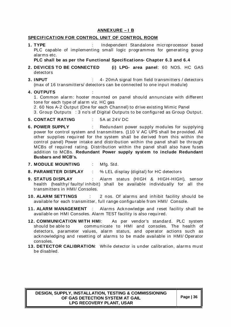
ANNEXURE – I B SPECIFICATION FOR CONTROL UNIT OF CONTROL ROOM 1. TYPE : Independent Standalone microprocessor based
PLC capable of implementing small logic programmes for generating group alarms etc.
PLC shall be as per the Functional Specifications- Chapter 6.3 and 6.4 2. DEVICES TO BE CONNECTED (i) LPG- area panel: 60 NOS. HC GAS
detectors
3. INPUT : 4- 20mA signal from field transmitters /detectors (max of 16 transmitters/detectors can be connected to one input module)
4. OUTPUTS : 1. Common alarm: hooter mounted on panel should annunciate with different tone for each type of alarm viz. HC gas 2. 60 Nos A-2 Output (One for each Channel) to drive existing Mimic Panel 3. Group Outputs : 3 no’s of Digital Outputs to be configured as Group Output.
5. CONTACT RATING : 5A at 24V DC
6. POWER SUPPLY : Redundant power supply modules for supplying power for control system and transmitters. (110 V AC UPS shall be provided. All other supplies required for the system shall be derived from this within the control panel) Power intake and distribution within the panel shall be through MCBs of required rating. Distribution within the panel shall also have fuses addition to MCBs. Redundant Power supply system to include Redundant Busbars and MCB’s.
7. MODULE MOUNTING : Mfg. Std.
8. PARAMETER DISPLAY : % LEL display (digital) for HC detectors
9. STATUS DISPLAY : Alarm status (HIGH & HIGH-HIGH), sensor health (healthy/faulty/inhibit) shall be available individually for all the transmitters in HMI/Consoles.
10. ALARM SETTINGS : 2 nos. Of alarms and inhibit facility should be available for each transmitter, full range configurable from HMI/ Console.
11. ALARM MANAGEMENT : Alarms Acknowledge and reset facility shall be available on HMI Consoles. Alarm TEST facility is also required.
12. COMMUNICATION WITH HMI: As per vendor’s standard. PLC system should be able to communicate to HMI and consoles. The health of detectors, parameter values, alarm status, and operator actions such as acknowledging and resetting of alarms to be made available in HMI/Operator consoles.
13. DETECTOR CALIBRATION: While detector is under calibration, alarms must be disabled.
DESIGN, SUPPLY, INSTALLATION, TESTING & COMMISSIONING OF GAS DETECTION SYSTEM AT GAIL
LPG RECOVERY PLANT, USAR Page | 37
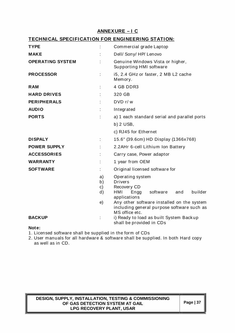
ANNEXURE – I C TECHNICAL SPECIFICATION FOR ENGINEERING STATION: TYPE : Commercial grade Laptop
MAKE : Dell/Sony/HP/Lenovo
OPERATING SYSTEM : Genuine Windows Vista or higher, Supporting HMI software
PROCESSOR : i5, 2.4 GHz or faster, 2 MB L2 cache Memory.
RAM : 4 GB DDR3
HARD DRIVES : 320 GB
PERIPHERALS : DVD r/w
AUDIO : Integrated
PORTS : a) 1 each standard serial and parallel ports
b) 2 USB,
c) RJ45 for Ethernet
DISPALY : 15.6" (39.6cm) HD Display (1366x768)
POWER SUPPLY : 2.2AHr 6-cell Lithium Ion Battery
ACCESSORIES : Carry case, Power adaptor
WARRANTY : 1 year from OEM
SOFTWARE : Original licensed software for
a) Operating system b) Drivers c) Recovery CD d) HMI Engg software and builder
applications e) Any other software installed on the system
including general purpose software such as MS office etc.
BACKUP : i) Ready to load as built System Backup shall be provided in CDs Note: 1. Licensed software shall be supplied in the form of CDs 2. User manuals for all hardware & software shall be supplied. In both Hard copy as well as in CD.

DESIGN, SUPPLY, INSTALLATION, TESTING & COMMISSIONING OF GAS DETECTION SYSTEM AT GAIL
LPG RECOVERY PLANT, USAR Page | 38
ANNEXURE – I D
SPECIFICATIONS FOR HMI WORKSTATION TYPE : Industrial grade PC
MAKE : Dell/Sony/HP/Lenovo
OPERATING SYSTEM : Windows XP/Professional / Vista
PROCESSOR : Intel Xenon processor 2.5 GHz or faster, 2 MB L2 cache memory
MEMORY : 2GB min.
HARD DRIVES : 250 GB (Depending on requirement)
PERIPHERALS : DVD r/w
AUDIO : Integrated
PORTS : a) Front 2 USB, b) Rear 4 USB c) 1 each standard serial and parallel ports, d) RJ45 for Ethernet
INPUT DEVICES : USB keyboard, USB optical mouse
MONITOR : 22”Flat panel LCD
WARRANTY : 2 years from OEM
SOFTWARE : Original licensed software for a) Operating system b) Drivers c) Recovery CD d) HMI software e) Any other software installed on the system
including general purpose software such as MS office etc.
BUZZER : Inbuilt buzzer required PRINTER : Colour Laser Printer for Logic, Alarm Sequence and Display Printout’s. To be connected to HMI Work-station
Note: 1. Licensed software shall be supplied in the form of CDs 2. User manuals for all hardware & software shall be supplied. In both Hard copy as well as in CD. 3. The configuration mentioned here is minimum requirement. The configuration at the time of supply should be the latest configuration available in market at that time and must be of a higher end version.

DESIGN, SUPPLY, INSTALLATION, TESTING & COMMISSIONING OF GAS DETECTION SYSTEM AT GAIL
LPG RECOVERY PLANT, USAR Page | 39
ANNEXURE – I E 6.19 SPECIFICATIONS FOR CONTROL PANELS
1.0 Installation Location : Indoor in Central Control Room. Safe area Flooring : False Flooring Air Conditioning : yes
2.0 General Details Type : Self supported free standing, Vertical, Rack design Make : RITTAL or Equivalent Dimensions : 2100 (H) x 850 (W) x 850 (D) Lighting : Required for inside panel Ventilation : Required with louvers. Door : Required rear door. Single door
3.0 Painting External : As per IS697/IS101 Internal : As per IS352/IS388 Color : Siemens Grey Finish : Non-glossy High Satin
4.0 Wiring Type : General type, intrinsically safe. Min 1 Sqmm for signal wiring. Min 1.5 Sqmm for Power wiring. 110VAC UPS wiring : Min 19strand, 16AWG copper conductor PVC insulated. 230VAC wiring : 2.5 Sqmm copper conductor PVC insulated. Signal wiring : Stranded, Mimimum 1.5 Sqmm copper conductor, PVC insulated. Terminals : Screw clamp type with pressure plates. Wiring color code : Power Supply: Red, Black and Green DC wiring : Red, Black Alarm system : White Control : Yellow Analog Signal : Light blue. Grounding : Grounding bus bar inside and grounding bolt outside
required.
5.0 NAME PLATES Panel shall have a name plate on white laminated plastic plate with black letters. All the control cards must be having tag plates indicating the tag nos connected to the card.
6.0 ACCESSORIES Cooling fans, redundant power supply, utility sockets and gland plate. Note: Unused slots on rack shall be provided with blind covers.

DESIGN, SUPPLY, INSTALLATION, TESTING & COMMISSIONING OF GAS DETECTION SYSTEM AT GAIL
LPG RECOVERY PLANT, USAR Page | 40
ANNEXURE – I F SPECIFICATIONS FOR JUNCTION BOXES
1. Junction boxes shall be explosion proof as per IS-2148 or equivalent 2. Junction boxes shall be weather proof as per NEMA4 or equivalent 3. Junction boxes shall be certified from statutory authorities like CMRI/PESO
etc for use in Hazardous area application. Copies of the certificates are to be provided.
4. Material of junction box shall be die cast Aluminum of minimum 5mm thick 5. All the terminals inside the junction Box shall be spring loaded, vibration
proof, Clip-on type mounted on Nickel plated steel rail complete with end cover and clamps.
6. Junction boxes shall be provided with earthing lugs. 7. Spare entries of Junction boxes shall be provided with certified explosion
proof plugs. 8. Minimum 20% spare terminals shall be provided in each Junction box. 9. Junction boxes sizing shall be done with due consideration for accessibility
and maintenance. Between JB walls and terminals a gap of 50 to 60mm on sides, 100mm on top and bottom, shall be maintained.
10. Surface shall be smooth and devoid of rust and scale. 2 coats of base primer and 2 final coats of epoxy based paint shall be applied both for interior and exterior surfaces.
11. Each Junction box shall have name plate permanently fixed on it at a visible location bearing the tag no and type of enclosure. Nameplate shall also bear the stamp of certifying agency with certificate number.
ANNEXURE – I G
SPECIFICATIONS FOR CALIBRATION KITS i) Hydrocarbon Gas detection kit Each hydrocarbon gas detector calibration kit shall contain a minimum of the following items.
a) High accuracy 50 % LEL Calibration gas (5 Ltrs) –10 bottles b) Regulator c) Pressure indicator d) Flow indicator e) Tubing f) Carrying case g) Calibration cup h) Certificate for calibration gas
ANNEXURE – I H
SPECIFICATION OF OPERATOR CONSOLE As per drawing on page 41.

DESIGN, SUPPLY, INSTALLATION, TESTING & COMMISSIONING OF GAS DETECTION SYSTEM AT GAIL
LPG RECOVERY PLANT, USAR Page | 41

DESIGN, SUPPLY, INSTALLATION, TESTING & COMMISSIONING OF GAS DETECTION SYSTEM AT GAIL
LPG RECOVERY PLANT, USAR Page | 42
ANNEXURE- II
INDICATIVE BILL OF MATERIAL
SL_NO DESCRIPTION Qty. 01. Design, Engineering, Inspection, Supply and Installation &
Commissioning of PLC based Gas Detection System which includes the following:
a. PLC with complete I/O as per specification b. Panel Cabinet with all internal wiring etc. as per
specification c. HMI as per specification d. Engineering Station(Laptop) as per specification e. Industrial Console as per attached drawing. f. Colour Laser Printer g. Licenses & System Software Packages
1 set
IR based Gas detector as per specification 20 nos.
02. Installation and Commissioning Services Lump Sum
03. Mandatory / Commissioning Spares as per Clause 6.10.1 Lump Sum
04. Priced List of Recommended Spares as per Clause 6.10.3 1
05. Documentation as per Clause 6.13 Set

DESIGN, SUPPLY, INSTALLATION, TESTING & COMMISSIONING OF GAS DETECTION SYSTEM AT GAIL
LPG RECOVERY PLANT, USAR Page | 43
ANNEXURE – III
Bidder to fill Bidders Compliance Column in Yes / No Any Deviation from Specification to be recorded and clearly noted by
Bidder. Separate Deviation Statement to be raised by Bidder clarifying
Deviations with respect to Specification in Detail.
ANNEXURE – III A
Sr. N SPECIFICATION DESCRIPTION FOR IR DETECTOR COMPILANCE (YES OR NO)
1 TYPE Explosion proof transmitter with integral sensor 2 SENSOR Dual beam/dual detector infra-red absorption.
3 GASES TO BE DETECTED
Hydrocarbon (methane, ethane, propane, butane)
4 RANGE 0-100% LEL 5 OUTPUT 4- 20 mA analog 6 CABLE ENTRY ¾” NPT (F) 7 CABLE GLAND Existing ¾ inch NPT (M) Gland to be used 8 RESPONSE TIME T90 <10 seconds. Without filter/weather cap 9 ACCURACY (+/-) 2% of reading at < 50 %LEL.
(+/-) 4 % of reading at > 50% LEL
10 REPEATABILITY (+/-) 2% LEL at 50% FSD 11 ZERO DRIFT (+/-) 2% FSD per year max 12 OP. TEMP. RANGE (-)10oC to + 65oC 13 HUMIDITY 5% TO 95% RH, non-Condensing. 14 POWER INPUT 12 TO 32 VDC 15 SELF TESTING
/FAULT MONITORING
Required
16 DISPLAY/ VISUAL IND
Indications pertaining to 1. Normal Functioning
2. Fault
3. Gas detection
4. Power supply
5. Other conditions, as per vendor specification
17
FILTERING SYSTEM
Must protect optics from dirt and water ingress.
DESIGN, SUPPLY, INSTALLATION, TESTING & COMMISSIONING OF GAS DETECTION SYSTEM AT GAIL
LPG RECOVERY PLANT, USAR Page | 44
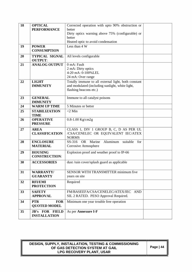
18 OPTICAL PERFORMANCE
Corrected operation with upto 90% obstruction or better Dirty optics warning above 75% (configurable) or better Heated optic to avoid condensation
19 POWER CONSUMPTION
Less than 4 W
20 TYPICAL SIGNAL OUTPUT:
All levels configurable
21 ANALOG OUTPUT 0 mA: Fault 2 mA: Dirty optics 4-20 mA: 0-100%LEL 24 mA: Over range
22 LIGHT IMMUNITY
Totally immune to all external light, both constant and modulated (including sunlight, white light, flashing beacons etc.)
23 GENERAL IMMUNITY
Immune to all catalyst poisons
24 WARM UP TIME 5 Minutes or better 25 STABILIZATION
TIME <2 Min
26 OPERATIVE PRESSURE
0.8-1.00 Kg/cm2g
27 AREA CLASSIFICATION
CLASS 1, DIV 1 GROUP B, C, D AS PER UL /CSA/CENELEC OR EQUIVALENT IEC/ATEX NORMS
28 ENCLOSURE MATERIAL
SS-316 OR Marine Aluminum suitable for Corrosive Atmosphere
29 HOUSING CONSTRUCTION:
Explosion proof and weather proof to IP-66
30 ACCESSORIES dust /rain cover/splash guard as applicable
31 WARRANTY/ GUARANTY
SENSOR WITH TRANSMITTER minimum five years on site
32 RFI/EMI PROTECTION
Required
33 SAFETY APPROVAL
FM/BASEEFA/CSA/CENELEC/ATEX/IEC AND SIL 2 RATED. PESO Approval Required.
34 PTR FOR QUOTED MODEL
Minimum one year trouble free operation
35 JB’s FOR FIELD INSTALLATION
As per Annexure I-F

DESIGN, SUPPLY, INSTALLATION, TESTING & COMMISSIONING OF GAS DETECTION SYSTEM AT GAIL
LPG RECOVERY PLANT, USAR Page | 45
ANNEXURE – III B Sr.N SPECIFICATION DESCRIPTION FOR PLC COMPLIANCE
(YES/NO) 1 TYPE Independent Standalone PLC
as per the Functional Specifications- Chapter 6.4
2 DEVICES TO BE CONNECTED
(i) LPG- area panel: 60 NOS. HC GAS detectors
3 INPUT 4- 20mA signal from field detectors. Total 60 nos. as per the Functional Specifications- Chapter 6.4
4 OUTPUTS Total 64 Nos Digital Outputs.
5 CONTACT RATING
5A at 24V DC
6 POWER SUPPLY Redundant power supply modules for supplying power for control system and transmitters. (110 V AC UPS shall be provided by GAIL. All other supplies required for the system shall be derived from this within the control panel) Power intake and distribution within the panel shall be through MCBs of required rating. Distribution within the panel shall also have fuses addition to MCBs. Redundant Power supply system to include Redundant Busbars and MCB’s.
7 MODULE MOUNTING & WIRING
Pre-wired and installed in Rittal Make Panel of Dimensions 2100(H) x 850(W) x 850 (D) As in Annexure I
8 Hooter Installed in Panel to give Audio indication on Alarm Condition in any Input Channel
9 PARAMETER DISPLAY
% LEL display (digital) for HC detectors
10 COMMUNICATION WITH HMI:
As per vendor’s standard. PLC system should be able to communicate to HMI and consoles. The health of detectors, parameter values, alarm status, and operator actions such as acknowledging and resetting of alarms to be made available in HMI/Operator consoles.
11 DETECTOR CALIBRATION:
While detector is under calibration, alarms must be disabled.
DESIGN, SUPPLY, INSTALLATION, TESTING & COMMISSIONING OF GAS DETECTION SYSTEM AT GAIL
LPG RECOVERY PLANT, USAR Page | 46
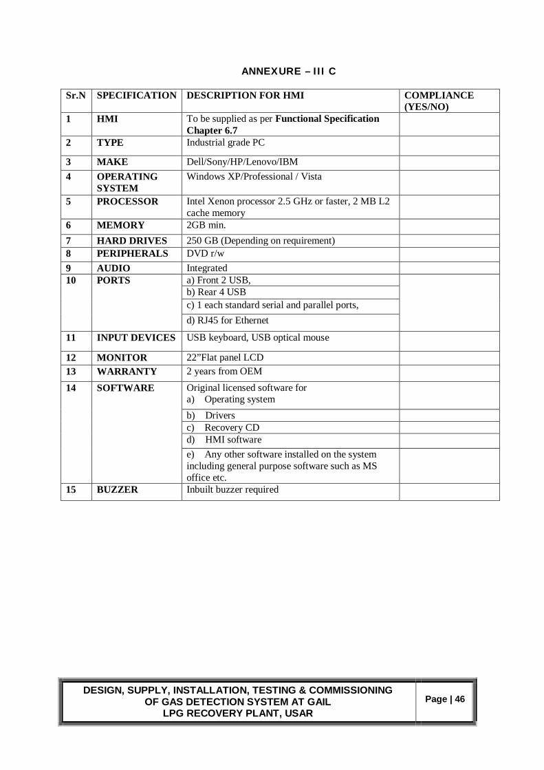
ANNEXURE – III C Sr.N SPECIFICATION DESCRIPTION FOR HMI COMPLIANCE
(YES/NO) 1
HMI To be supplied as per Functional Specification Chapter 6.7
2 TYPE Industrial grade PC
3 MAKE Dell/Sony/HP/Lenovo/IBM 4 OPERATING
SYSTEM Windows XP/Professional / Vista
5 PROCESSOR Intel Xenon processor 2.5 GHz or faster, 2 MB L2 cache memory
6 MEMORY 2GB min. 7 HARD DRIVES 250 GB (Depending on requirement) 8 PERIPHERALS DVD r/w 9 AUDIO Integrated 10 PORTS a) Front 2 USB,
b) Rear 4 USB c) 1 each standard serial and parallel ports, d) RJ45 for Ethernet
11 INPUT DEVICES USB keyboard, USB optical mouse
12 MONITOR 22”Flat panel LCD 13 WARRANTY 2 years from OEM
14 SOFTWARE Original licensed software for a) Operating system
b) Drivers c) Recovery CD d) HMI software e) Any other software installed on the system including general purpose software such as MS office etc.
15 BUZZER Inbuilt buzzer required

DESIGN, SUPPLY, INSTALLATION, TESTING & COMMISSIONING OF GAS DETECTION SYSTEM AT GAIL
LPG RECOVERY PLANT, USAR Page | 47
ANNEXURE – III D Sr. N
SPECIFICATION DESCRIPTION FOR ENGG CONSOLE COMPLIANCE (YES/NO)
1 ENGG CONSOLE
Laptop as per Functional Specifications 6.6
2 TYPE Commercial grade Laptop 3 MAKE Dell/Sony/HP/Lenovo
4 OPERATING SYSTEM
Genuine Windows Vista or higher, Supporting HMI software
5 PROCESSOR i5, 2.4 GHz or faster, 2 MB L2 cache Memory. 6 RAM 4 GB DDR3 7 HARD DRIVES 320 GB 8 PERIPHERALS DVD r/w 9 AUDIO Integrated 10 PORTS a) 1 each standard serial and parallel ports
b) 2 USB, c) RJ45 for Ethernet
11 DISPALY 15.6" (39.6cm) HD Display (1366x768) 12 POWER SUPPLY 2.2AHr 6-cell Lithium Ion Battery 13 ACCESSORIES Carry case, Power adaptor 14 WARRANTY 1 year from OEM 15 SOFTWARE Original licensed software for
a) Operating system
b) Drivers c) Recovery CD d) HMI Engg software and builder applications
e) Any other software installed on the system including general purpose software such as MS office etc.
16 BACKUP Ready to load as built System Backup shall be provided in CDs

DESIGN, SUPPLY, INSTALLATION, TESTING & COMMISSIONING OF GAS DETECTION SYSTEM AT GAIL
LPG RECOVERY PLANT, USAR Page | 48
ANNEXURE – III E Sr. N
SPECIFICATION DESCRIPTION FOR CONTROL PANEL AND INDUSTRIAL CONSOLE FOR HMI
COMPLIANCE (YES/NO)
1 CONTROL PANEL
Located in CCR
2 TYPE Self-supported free standing, Vertical, Rack design 3 MAKE RITTAL 4 DIMENSIONS 2100 (H) x 850 (W) x 850 (D) 5 LIGHTING Required for inside panel 6 VENTILATION Required with louvers. 7 DOOR Required rear door. Single door 8 COLOUR Siemens Grey ( Non Glossy High Satin ) 9 ACCESSORIES Cooling fans, utility sockets and gland plate. 10 UTILITY POWER
SUPPLY 230 V AC
11 METALLIC INDUSTRIAL CONSOLE
Colour Scheme, Dimensions and Specification as per Scheme on Page 41
12 ACCESSORIES Cooling fans, utility sockets and gland plate. 13 UTILITY POWER
SUPPLY 230 V AC
ANNEXURE – III F
Sr. N
SPECIFICATION DESCRIPTION FOR CALIBRATION KIT COMPLIANCE (YES/NO)
1. CALIBRATION KITS
Required as per Specified in Annexure 1-G
ANNEXURE – III G
Sr. N
SPECIFICATION DESCRIPTION FOR COLOUR PRINTER COMPLIANCE (YES/NO)
1. COLOUR PRINTER
LASERJET ( HP/ CANON/KODAK) Connected to HMI Workstation for ALARM , LOGIC AND DISPLAY PRINTOUT’s
ANNEXURE – III H
Sr. N
SPECIFICATION SERVICES COMPLIANCE (YES/NO)
1 INSPECTION & TESTING
Considered in scope of bidder as per CLAUSE 6.9
1. INSTALLATION COMMISSIONING
Considered in scope of bidder as per CLAUSE 6.11
2 TRAINING Considered in scope of bidder as per CLAUSE 6.14

DESIGN, SUPPLY, INSTALLATION, TESTING & COMMISSIONING OF GAS DETECTION SYSTEM AT GAIL
LPG RECOVERY PLANT, USAR Page | 49
VENDOR LIST
1. SENSOR / TRANSMITTER
1. DETECTOR ELECTRONIC CORPORATION (DETRONICS) 2. JOSEPH LESLIE DRAGER 3. GENERAL MONITOR 4. HONEYWELL (ZELLWEGGR) 5. SEIGER 6. GASTECH 7. NET SAFETY 8. MSA 9. OLD HAM 10. DETECTION INSTRUMENTS 11. IST
2. PLC / PROGRAMMABLE ELECTRONIC SYSTEM
1. ROCKWELL AUTOMATION 2. YOKOGAWA 3. SIEMENS 4. HONEYWELL 5. GE- FANUC 6. MITSUBISHI ELECTRIC CORP
3. PANEL CABINET
1. RITTAL
4. INDUSTRIAL CONSOLE 1. PYROTECH 2. RAY-HANS 3. OTHER REPUTED MANUFACTURERS (AS CLEARED BY GAIL
DURING DETAILED ENGG)
5. CABLE
1. ASSOCIATED CABLES 2. ASSOCIATED FLEXIBLES AND WIRES 3. BROOKS CABLE WORKS 4. UDEY PYRO 5. UNIVERSAL CABLES 6. POLYCAB WIRES 7. RADIANT CABLES
6. JUNCTION BOXES AND CABLE GLANDS
1. BALIGA LIGHTING AND EQPMT 2. FCG FLAME PROOF CONTROL GEARS 3. FLAME PROOF EQPMT 4. FLEXPRO
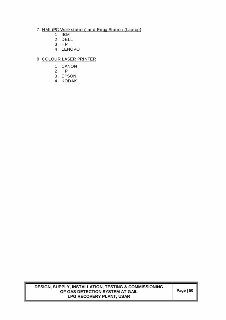
DESIGN, SUPPLY, INSTALLATION, TESTING & COMMISSIONING OF GAS DETECTION SYSTEM AT GAIL
LPG RECOVERY PLANT, USAR Page | 50
7. HMI (PC Workstation) and Engg Station (Laptop) 1. IBM 2. DELL 3. HP 4. LENOVO
8. COLOUR LASER PRINTER
1. CANON 2. HP 3. EPSON 4. KODAK