delivery specifications · delivery specifications 1.scope these specifications apply to quartz...
TRANSCRIPT
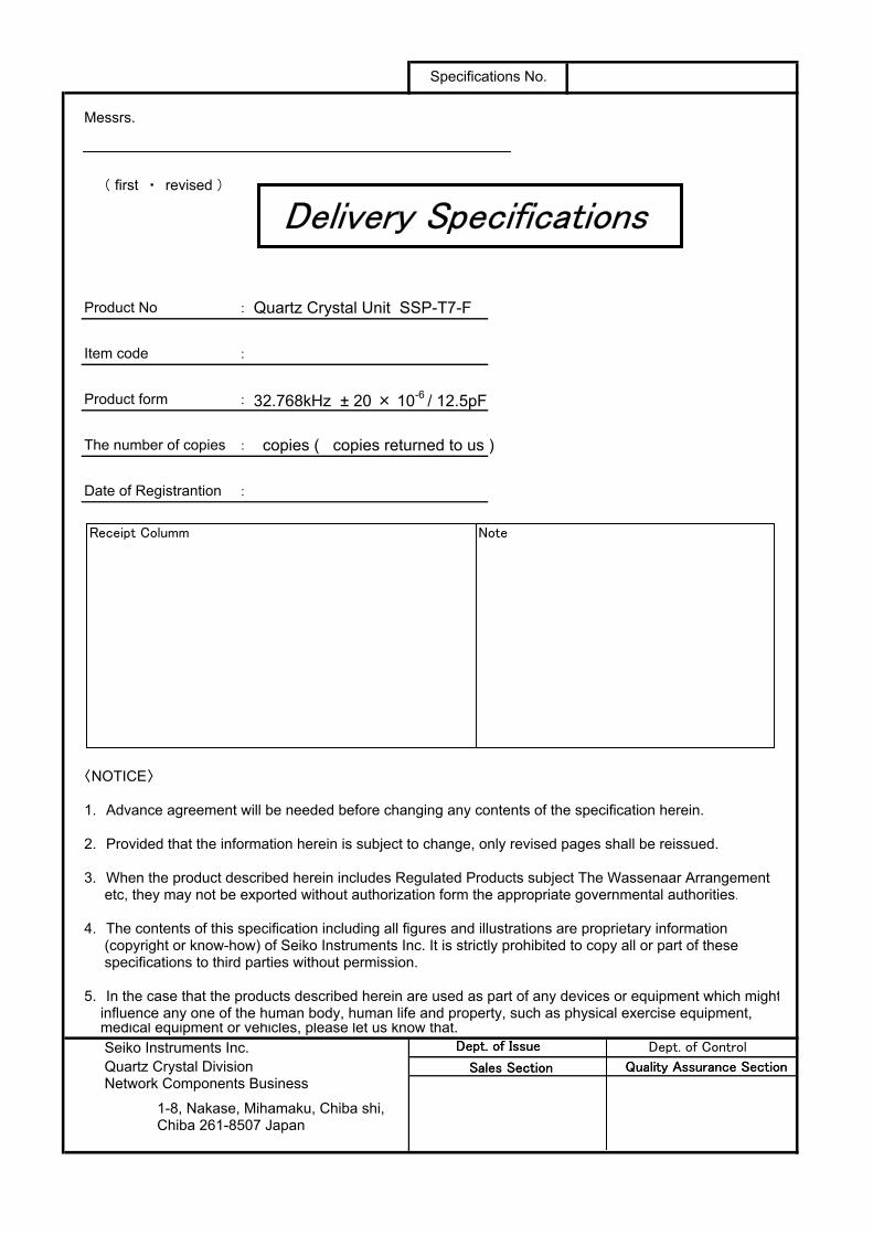
Messrs.
( first ・ revised )
Product No : Quartz Crystal Unit SSP-T7-F
Item code :
Product form : 32.768kHz ± 20 × 10-6 / 12.5pF
The number of copies : copies ( copies returned to us )
Date of Registrantion :
〈NOTICE〉
1. Advance agreement will be needed before changing any contents of the specification herein.
2. Provided that the information herein is subject to change, only revised pages shall be reissued.
3. When the product described herein includes Regulated Products subject The Wassenaar Arrangement etc, they may not be exported without authorization form the appropriate governmental authorities.
4. The contents of this specification including all figures and illustrations are proprietary information (copyright or know-how) of Seiko Instruments Inc. It is strictly prohibited to copy all or part of these specifications to third parties without permission.
5. In the case that the products described herein are used as part of any devices or equipment which might influence any one of the human body, human life and property, such as physical exercise equipment, medical equipment or vehicles, please let us know that. Seiko Instruments Inc. Quartz Crystal Division Network Components Business
1-8, Nakase, Mihamaku, Chiba shi,Chiba 261-8507 Japan
Specifications No.
Delivery Specifications
Receipt Columm Note
Dept. of Issue
Sales Section Quality Assurance Section
Delivery Specifications
Receipt Columm Note
Dept. of Issue
Sales Section Quality Assurance Section
Dept. of Control
1/11
Delivery Specifications1.Scope
These specifications apply to QUARTZ CRYSTAL RESONATORS ( hereinafter referred to as RESONATORS ) to be manufactured by Seiko Instruments Inc.( hereinafter referred to as SII ) to
2.Designation
RESONATORS are designated " SSP-T7-F"(32.768kHz ).
3.Shape and dimensions
As per the SSP-T7-F drawing shown on page 5 .
4.Electrical characteristics
Specified on page 2 through 3.
5.Shipment and packaging
5.1 (3,000) pcs are the standard lot size to which the lot number shall be allotted5.2 The packaging shall conform to the resonator packaging standards.
6.Outgoing inspection
6.1 When mutually agreed, the outgoing inspection shall be conducted as per the standard on page 4.
6.2 The outgoing inspection slip is not basically affixed to each packaging.
7.Warranty
In the event that any defective RESONATORS or defective lot is found atincoming inspection at and that any defect resulting from failures in process-control at SII after incominginspection is found, good RESONATORS shall be supplied to free of charge as a replacement .In the event that any trouble or problems rising directly from RESONATORSoccurs, it will be amicably settled between both parties, provided that warranty shall be done within the score of replacement of good RESONATORS.
8.Amendment or abolition of the specifications
Amendment or abolition of the specifications shall be made upon mutual consentbetween and SII. If any problem arises ,it shall be amicably settled between both parties.
9.Effectiveness of the specifications
These specifications are effective after receipt of returned copies with yourapproved sign.
2/11
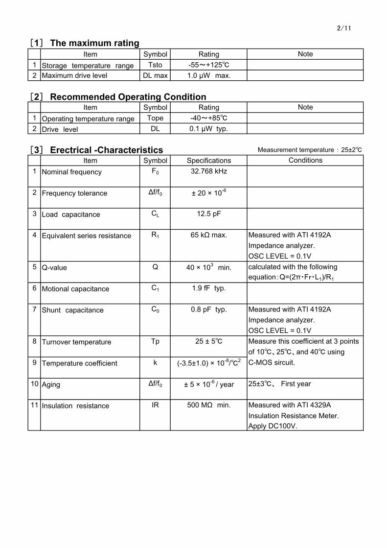
[1] The maximum ratingItem Symbol Rating
1 Storage temperature range Tsto -55~+1252 Maximum drive level DL max 1.0 µW max.
[2] Recommended Operating ConditionItem Symbol Rating
1 Operating temperature range Tope -40~+852 Drive level DL 0.1 µW typ.
[3] Erectrical -Characteristics Measurement temperature : 25±2
Item Symbol Specifications1 Nominal frequency F0 32.768 kHz
2 Frequency tolerance ∆f/f0 ± 20 × 10-6
3 Load capacitance CL 12.5 pF
4 Equivalent series resistance R1 65 kΩ max. Measured with ATI 4192AImpedance analyzer.OSC LEVEL = 0.1V
5 Q-value Q 40 × 103 min. calculated with the following
equation:Q=(2π・Fr・L1)/R1
6 Motional capacitance C1 1.9 fF typ.
7 Shunt capacitance C0 0.8 pF typ. Measured with ATI 4192AImpedance analyzer.OSC LEVEL = 0.1V
8 Turnover temperature Tp 25 ± 5 Measure this coefficient at 3 pointsof 10、25、and 40 using
9 Temperature coefficient k (-3.5±1.0) × 10-8/2 C-MOS sircuit.
10 Aging ∆f/f0 ± 5 × 10⁻⁶ / year 25±3、 First year
11 Insulation resistance IR 500 MΩ min. Measured with ATI 4329AInsulation Resistance Meter.Apply DC100V.
Conditions
Note
Note
3/11
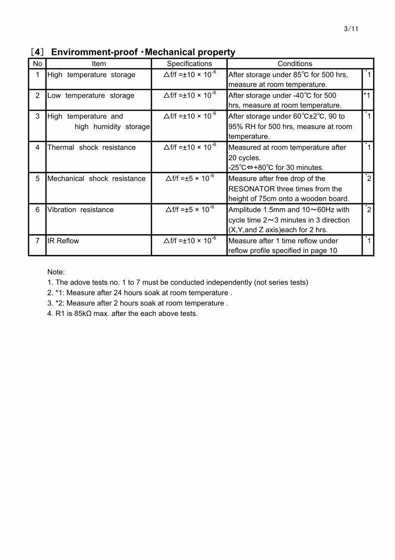
[4] Enviromment-proof ・Mechanical propertyNo Item Specifications Conditions1 High temperature storage f/f =±10 × 10-6 After storage under 85 for 500 hrs, *1
measure at room temperature.2 Low temperature storage f/f =±10 × 10-6 After storage under -40 for 500 *1
hrs, measure at room temperature.3 High temperature and f/f =±10 × 10-6 After storage under 60±2, 90 to *1
high humidity storage 95% RH for 500 hrs, measure at roomtemperature.
4 Thermal shock resistance f/f =±10 × 10-6 Measured at room temperature after *120 cycles.-25⇔+80 for 30 minutes.
5 Mechanical shock resistance f/f =±5 × 10⁻⁶ Measure after free drop of the *2RESONATOR three times from theheight of 75cm onto a wooden board.
6 Vibration resistance f/f =±5 × 10⁻⁶ Amplitude 1.5mm and 10~60Hz with *2cycle time 2~3 minutes in 3 direction(X,Y,and Z axis)each for 2 hrs.
7 IR Reflow f/f =±10 × 10-6 Measure after 1 time reflow under *1reflow profile specified in page 10
Note:1. The adove tests no. 1 to 7 must be conducted independently (not series tests)2. *1: Measure after 24 hours soak at room temperature .3. *2: Measure after 2 hours soak at room temperature .4. R1 is 85kΩ max. after the each above tests.

4/11
[5] Precautions
(1) Recommended mounting conditionsReflow profile As per reflow profile shown in page 11.Manual soldering 350 max. for 4 sec. max.
(2) CleaningThe crystal resonator may be destroyed by ultrasonic cleaning.We don't the quarantee the quality of the product with that cleaning method because such conditions as type of the washing machine, power, time,position in the bath,etc. can not be specified.Please confirm ultrasonic cleaning is not giving any damage to the productbefore use when that cleaning method must be used.
[6] Outgoing inspection standard
・The outgoing inspection shall be conducted as per the following standard .
・The sampling shall be performed according to the ANSI/ASQCZ1.4-1996 .
No Sampling level AQL(%)
1 Frequency tolerance 1.02 Equivalent series resistance 1.03 Outer appearance 1.54 Others characteristics Periodical quality inspection
Item
Ⅰ
Ⅰ
Ⅰ
5/11
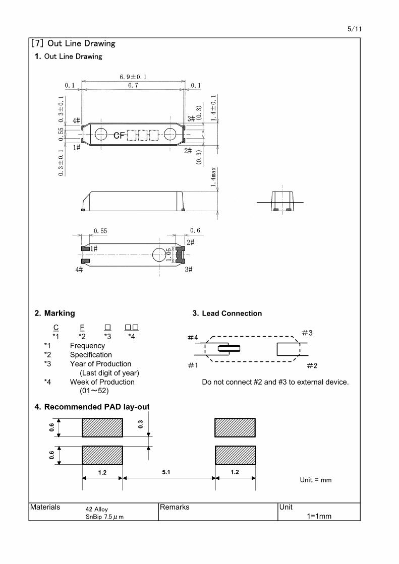
[7] Out Line Drawing
1. Out Line Drawing
2. Marking 3. Lead Connection
C F *1 *2 *3 *4
*1 Frequency*2 Specification*3 Year of Production
(Last digit of year)*4 Week of Production Do not connect #2 and #3 to external device.
(01~52)
4. Recommended PAD lay-out
Unit = mm
Materials Remarks Unit1=1mm
#4#3
#2#1
0.6
5.1 1.2
0.3
0.6
1.2
0.6
5.1 1.2
0.3
0.6
1.2
0.6
5.1 1.2
0.3
0.6
1.2
0.6
5.1 1.2
0.3
0.6
1.2
CF
42 AlloySnBip 7.5μm

6/11
1.Drawing of tape dimensions① Carrier tape see Drawing page 8.② Reel for carrier tape see Drawing page 9.
2.Material① Carrier tape : A-PET② Reel for carrier tape : MPPE
3.Taping method(1) Components shall be placed in tapes in such manner as to assure
that marking of the components is visible as per Fig. 1
User direction of feed
(2) Reel① On the side of reel there shall be more than 20 blocks of "No components".② The beginning of Carrier Tape shall be bent vertically and hooked on groove of reel.
(3) Leader① On the side of leader, there shall be more than 20 blocks of "No components "② The length of Leader shall be over 400 mm.③ The Length of Stick Tape for Cover Tape shall be about 100 mm and Stick Tape shall never be detached.
Fig. 2
User direction of feed
[8]Taping specification
Fig. 1
Stick TapeCarrier Tape Cover Tape
ComponentsNo Components
No Components
markin
g
markin
g
markin
g
Stick TapeCarrier Tape Cover Tape
Components Leader
No Components
No Components
markin
g
markin
g
markin
g
7/11
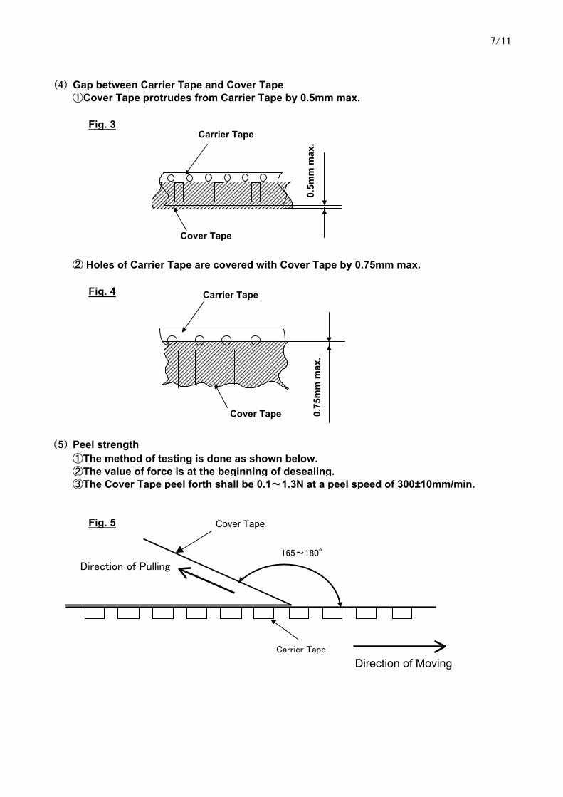
(4) Gap between Carrier Tape and Cover Tape①Cover Tape protrudes from Carrier Tape by 0.5mm max.
Fig. 3
② Holes of Carrier Tape are covered with Cover Tape by 0.75mm max.
Fig. 4
(5) Peel strength①The method of testing is done as shown below.②The value of force is at the beginning of desealing.③The Cover Tape peel forth shall be 0.1~1.3N at a peel speed of 300±10mm/min.
Fig. 5
Direction of Moving
Carrier Tape
Cover Tape
0.5m
m m
ax.
Carrier Tape
Cover Tape 0.75
mm
max
.
Cover Tape
165~180°
Carrier Tape
Direction of Pulling
8/11
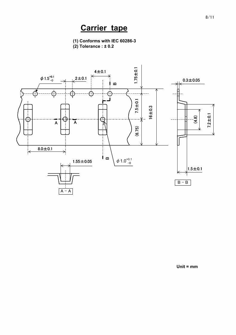
Carrier tape(1) Conforms with IEC 60286-3(2) Tolerance : ± 0.2
φ1.0+0.1
Unit = mm
φ1.5+0.1
AA
B
4±0.1
8.0±0.1
B - B
2±0.1
B
1.7
5±
0.1
7.5
±0.1
16±
0.3
7.2
±0.1
0.3±0.05
1.5±0.1
(4.8
)A - A
-0
-0
(6.7
5)
1.55±0.05
φ1.5+0.1
AA
B
4±0.1
8.0±0.1
B - B
2±0.1
B
1.7
5±
0.1
7.5
±0.1
16±
0.3
7.2
±0.1
0.3±0.05
1.5±0.1
(4.8
)A - A
-0
-0
(6.7
5)
1.55±0.05

9/11
Taping reel(1) Conforms with IEC 60286-3(2) Quantity per reel : 3,000pcs./ for a reel
Unit = mm
10/11
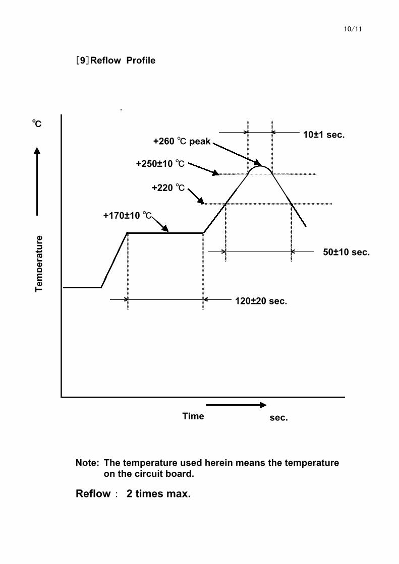
[9]Reflow Profile
Note: The temperature used herein means the temperature on the circuit board.
Reflow : 2 times max.
+260 peak.
50±10 sec.
120±20 sec.
10±1 sec.
+250±10
+220
+260 peak.
50±10 sec.
120±20 sec.
10±1 sec.
+250±10
+220
+260 peak.
50±10 sec.
120±20 sec.
10±1 sec.
+250±10
+220
+260 peak.
50±10 sec.
120±20 sec.
10±1 sec.
+250±10
+220
Tem
pera
ture
Time
+260 peak.
50±10 sec.
120±20 sec.
10±1 sec.
+250±10
+220
+260 peak.
50±10 sec.
120±20 sec.
10±1 sec.
+250±10
+220
+260 peak.
50±10 sec.
120±20 sec.
10±1 sec.
+250±10
+220
+260 peak.
50±10 sec.
120±20 sec.
10±1 sec.
+250±10
+220
Tem
pera
ture
Time
+260 peak.
50±10 sec.
120±20 sec.
10±1 sec.
+250±10
+220
+260 peak.
50±10 sec.
120±20 sec.
10±1 sec.
+250±10
+220
+260 peak.
50±10 sec.
120±20 sec.
10±1 sec.
+250±10
+220
+260 peak.
50±10 sec.
120±20 sec.
10±1 sec.
+250±10
+220
Tem
pera
ture
Time
+260 peak.
50±10 sec.
120±20 sec.
10±1 sec.
+250±10
+220
+260 peak.
50±10 sec.
120±20 sec.
10±1 sec.
+250±10
+220
+260 peak.
50±10 sec.
120±20 sec.
10±1 sec.
+250±10
+220
+260 peak.
50±10 sec.
120±20 sec.
10±1 sec.
+250±10
+220
Tem
pera
ture
Time
+260 peak.
50±10 sec.
120±20 sec.
10±1 sec.
+250±10
+220
+260 peak.
50±10 sec.
120±20 sec.
10±1 sec.
+250±10
+220
+260 peak.
50±10 sec.
120±20 sec.
10±1 sec.
+250±10
+220
+260 peak.
50±10 sec.
120±20 sec.
10±1 sec.
+250±10
+220
Tem
pera
ture
Time
+260 peak.
50±10 sec.
120±20 sec.
10±1 sec.
+250±10
+220
+260 peak.
50±10 sec.
120±20 sec.
10±1 sec.
+250±10
+220
+260 peak.
50±10 sec.
120±20 sec.
10±1 sec.
+250±10
+220
+260 peak.
50±10 sec.
120±20 sec.
10±1 sec.
+250±10
+220
Tem
pera
ture
Time
+260 peak.
50±10 sec.
120±20 sec.
10±1 sec.
+250±10
+220
+260 peak.
50±10 sec.
120±20 sec.
10±1 sec.
+250±10
+220
+260 peak.
50±10 sec.
120±20 sec.
10±1 sec.
+250±10
+220
+260 peak.
50±10 sec.
120±20 sec.
10±1 sec.
+250±10
+220
Tem
pera
ture
Time
+260 peak.
50±10 sec.
120±20 sec.
10±1 sec.
+250±10
+220
+260 peak.
50±10 sec.
120±20 sec.
10±1 sec.
+250±10
+220
+260 peak.
50±10 sec.
120±20 sec.
10±1 sec.
+250±10
+220
+260 peak
+170±10
50±10 sec.
120±20 sec.
10±1 sec.
+250±10
+220
Tem
pera
ture
Time
sec.
11/11
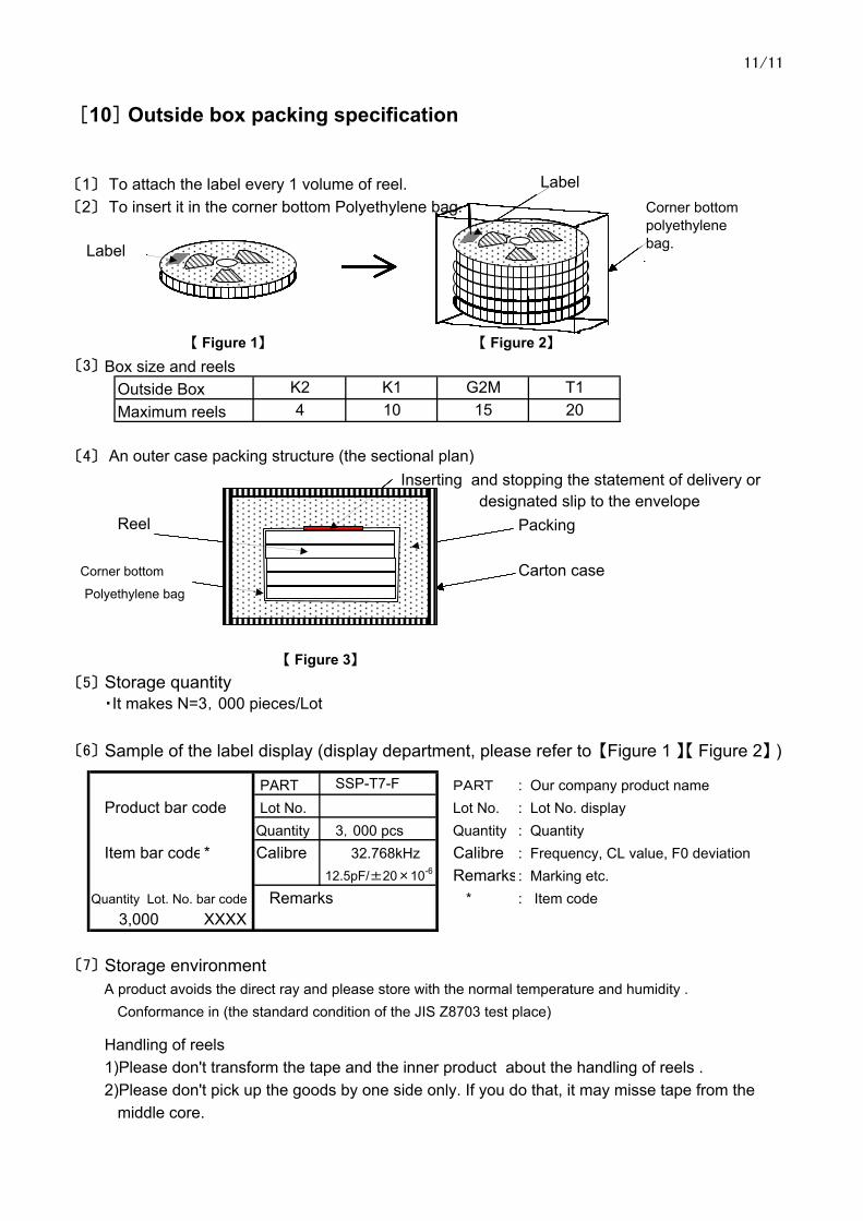
[10] Outside box packing specification
〔1〕 To attach the label every 1 volume of reel. 〔2〕 To insert it in the corner bottom Polyethylene bag.
【 Figure 1】 【 Figure 2】
〔3〕 Box size and reels
〔4〕 An outer case packing structure (the sectional plan) Inserting and stopping the statement of delivery or
designated slip to the envelopeReel Packing
Corner bottom Carton casePolyethylene bag
【 Figure 3】
〔5〕 Storage quantity ・It makes N=3,000 pieces/Lot
〔6〕 Sample of the label display (display department, please refer to 【Figure 1 】【 Figure 2】 )
SSP-T7-F PART : Our company product name Product bar code Lot No. : Lot No. display
3,000 pcs Quantity : Quantity Item bar code* Calibre : Frequency, CL value, F0 deviation
Remarks: Marking etc. Remarks * : Item code
XXXX
〔7〕 Storage environmentA product avoids the direct ray and please store with the normal temperature and humidity .
Conformance in (the standard condition of the JIS Z8703 test place)
Handling of reels1)Please don't transform the tape and the inner product about the handling of reels . 2)Please don't pick up the goods by one side only. If you do that, it may misse tape from the
middle core.
12.5pF/±20×10-6
Outside BoxMaximum reels
K2 K14 10
32.768kHz
3,000
PART Lot No.QuantityCalibre
Quantity Lot. No. bar code
G2M T115 20
Label
LabelCornerbottom vinylb
Label
LabelCornerbottom vinylb
Label
LabelCornerbottom vinylb
Label
LabelCornerbottom vinylb
Label
LabelCornerbottom vinylb
Label
LabelCornerbottom vinylb
Label
LabelCornerbottom vinylb
Label
LabelCornerbottom vinylb
Label
LabelCornerbottom vinylb
Label
LabelCornerbottom vinylb
Label
LabelCornerbottom vinylb
Label
LabelCornerbottom vinylb
Label
LabelCornerbottom vinylb
Label
Label
Label
LabelLabel
Corner bottompolyethylenebag.