scale verticali “ce” inspection manhole frp … verticali... · pagina 1 scale verticali...
TRANSCRIPT

PAGINA 1
SCALE VERTICALI “CE” MM13
30.07.2015 Rev. 3
INSPECTION MANHOLE FRP FIXED DOUBLE STILE LADDERS - MARKED CE
COMPOSITE SOLUTION

PAGINA 2
SUMMARY
1. USES AND CHARACTERISTICS ...................................................................................................................................... 3
2. REFERENCE NORMS AND COMPULSORY USES ....................................................................................................... 4
3. EMPLOYMENT FIELDS ....................................................................................................................................................... 5
4. MATERIALS .......................................................................................................................................................................... 6
4.1 PARTS OF THE ISPECTION MANHOLE FRP FIXED VERTICAL LADDERS ..................................................... 6
4.2 VERTICAL STILES TABLE ........................................................................................................................................ 6
4.3 RUNG PROFILES TABLE ......................................................................................................................................... 7
4.4 FIXING CLAMPS TABLE ............................................................................................................................................. 7
4.5 FIXING DEVICES TABLE ............................................................................................................................................ 7
5. DIMENSIONS OF THE LADDERS ...................................................................................................................................... 9
6. TYPES OF LADDERS ....................................................................................................................................................... 10
6.1 INSPECTION MANHOLE VERTICAL LADDER TYPE 1 .................................................................................... 10
6.2 INSPECTION MANHOLE VERTICAL LADDER TYPE 2 ................................................................................... 10
6.3 INSPECTION MANHOLE VERTICAL LADDER TYPE 3 ................................................................................... 10
7. ASSEMBLING INSTRUCTIONS ..................................................................................................................................... 11

PAGINA 3
1. USE AND CHARACTERISTICS
The FRP ladders are built by assembling the fiberglass and polyester resin profiles, they assure several advantages compared to the normal metal ones:
a. High resistance to chemical and atmospheric aggressions
b. High mechanical/weight ratio peso c. Long-lasting d. Lightness
e. Dimensional stability
f. High dielectric properties g. No maintenance
h. Easy to install The double stile FRP ladders are used for fixed and permanent installations inside inspection manholes of wastewater, rainwater, surface water (except for national norms where requested) and potable water environments.
The main objective is to allow a safe access to people.
The double stile FRP fixed ladders for inspection manholes are distinguished by a specific label accordingly to the UE 305/2011 regulation.

PAGINA 4
2. REFERENCE NORMS
Ladders are designed and built accordingly to the following norms:
UNI EN 14396/2004 Fixed ladders for inspection manholes.
This standard applies to permanent fixed ladders in manholes. It specifies the performance criteria for the mechanical stability and resistance providing protection against falling. The ladders specified in this European Standard are suitable for use in sewage, rainwater, surface water and, subject to requirements of national regulations, potable water environments. The norm reports the regulation for the CE marking of the products.
(UE) 305/2011 REGULATION European Regulation for construction materials (which abrogates the 89/106/CEE directive)
This regulation establishes the conditions for the introduction of construction materials on the market. Also establishes the evaluation criteria of the performances for these products and the CE marking using procedure.

PAGINA 5
3. EMPLOYMENT FIELDS
M.M. INSPECTION MANHOLES FRP FIXED DOUBLE STILE LADDERS WITH CE MARKING, are dedicated to fixed and permanent installations inside inspection manholes of wastewater, rainwater, surface water (except if subject to requirements of national regulations) and potable water environments and their main objective is to allow a safe access to people.
Their properties are mostly enhanced and allow a rational use mainly in corrosive environments. Above all their characteristics are emphasized in those in plants where conventional materials are not long lasting or need continuous varnishing or protection with high maintenance costs and, in any case, do not guarantee safety in the working environment.
The industries that use MM’s FRP ladders for inspection manholes are:
• Chemical Industries
• Galvanic plants
• Mineral industries
• Textile industries
• Food industries
• Electric stations
• Electric distribution cabins
• Oil plants
• Tanneries
• Water treatment plant
• Surge tanks
• Marine field
• Paper factories

PAGINA 6
4. MATERIALS
4.1 PARTS OF THE INSPECTION MANHOLE FIXED LADDERS
Legend
1. Anchor bracket 2. Stile 3. Rung
4.2 STILE PROFILES TABLE
PROFILES CODE DESCRIPTION DIMENSIONS (mm)
BARS LENGTH (m)
WEIGHT (Kg/m) COLOR
53R58253I Stile
Ladder type 02 58x25x3 6 0.80 Grey
RAL 7035
53R85253I Stile Ladder type 01 85x25x3 6 1.17 Grey
RAL 7035
53C90358I Stile
Ladder type 03 90x35x8 6 2.10 Grey
RAL 7035

PAGINA 7
4.3 RUNG PROFILES TABLE
PROFILES CODE DESCRIPTION DIMENSIONS (mm)
BARS LENGTH (m)
WEIGHT (Kg/m) COLOR
*
53O2821.3I Antiskid rung Ø 28x21.3 6 0.50 Grey RAL 7035
4.4 ANCHOR BRACKETS TABLE
CLAMPS CODE DESCRIPTION DIMENSIONS (mm) COLOR
56ASTAFFA5 S.S. AISI 316 wall and floor anchor bracket
A: 228 B: 50 C: 70 Th. 3
-
CSTAFFA12 FRP E23 pultruded wall anchor brackets
A: 285 B: 100 C: 60 Th. 15
Grey RAL 7035
CPIASTRA1 FRP counter-plate for bracket fixing on ladder type 1
A: 85 B: 70 Th. 3
Grey RAL 7035
CPIASTRA2 FRP counter-plate for bracket fixing on ladder type 2
A: 58 B: 70 Th. 3
Grey RAL 7035
4.5 FIXING DEVICES TABLE
PROFILES CODE DESCRIPTION DIMENSIONS (mm) COLOR
53P5825I FRP rung fixing block 70X58 Th. 25
Grey RAL 7035
5306I FRP rung fixing pin Ø 6 mm
Grey RAL 7035
S.S. BOLTS & NUTS CODE DESCRIPTION DIMENSIONS -
AISI 316 S.S. SCREWS 56 Screw used for the fixing of the S.S. bracket to the stile, for ladder types 1 and 2
M8x40 screw -
AISI 316 S.S. SCREWS 56 Screw used for the fixing of the S.S. bracket to the stile, for ladder type 3
M8x25 screw -
AISI 316 S.S. SCREWS 56 Screw used for the fixing of the FRP bracket
to the stile, for ladder types 1 and 2 M8x50 screw -
AISI 316 S.S. SCREWS 56 Screw used for the fixing of the FRP bracket to the stile, for ladder type 3
M8x35 screw -
AISI 316 S.S. SCREWS 56 Screw used for the fixing of the rings to the vertical rod, types 1 and 2 M8x45 screw -
AISI 316 S.S. SCREWS 56 Screw used for the fixing of the rings to the vertical rod, type 3
M8x30 screw -
AISI 316 S.S. SCREWS 56 Button head screw for the fixing of the flat profiles on the rings M6x25 screw -
AISI 316 WASHERS 56 56 washers
M8 M6 -
AISI 316 BOLTS 56 56 bolts M8
M6 -

PAGINA 8
ANCHOR BOLTS CODE DESCRIPTION DIMENSIONS (mm) -
FM 753 CRACK M10
Galvanized steel high performance
pass-through anchor bolt for
cracked concrete
M10x105 -
FM753 A4 M12 S.S. high performance pass-
through anchor bolt M12x110 -
PAGINA 9
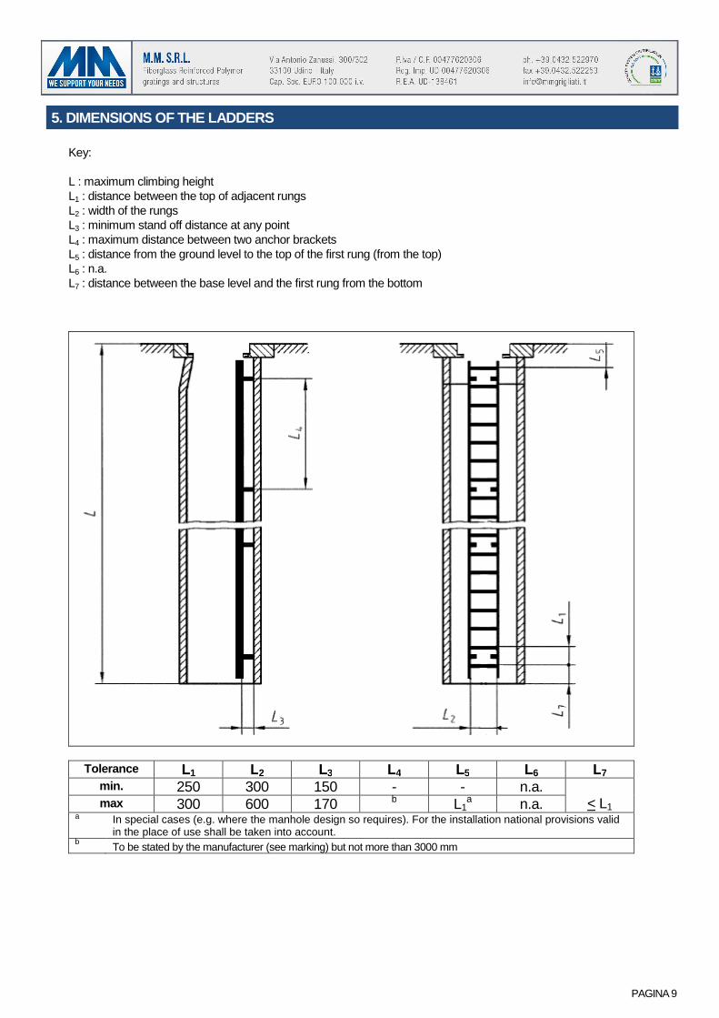
5. DIMENSIONS OF THE LADDERS
Key:
L : maximum climbing height L1 : distance between the top of adjacent rungs L2 : width of the rungs L3 : minimum stand off distance at any point L4 : maximum distance between two anchor brackets L5 : distance from the ground level to the top of the first rung (from the top) L6 : n.a. L7 : distance between the base level and the first rung from the bottom
Tolerance L1 L2 L3 L4 L5 L6 L7 min. 250 300 150 - - n.a.
< L1 max 300 600 170 b L1a n.a.
a In special cases (e.g. where the manhole design so requires). For the installation national provisions valid in the place of use shall be taken into account.
b To be stated by the manufacturer (see marking) but not more than 3000 mm

PAGINA 10
6. TYPES OF LADDERS
6.1 INSPECTION MANHOLE LADDER TYPE 1
CSCALA1 CE – INSPECTION MANHOLE LADDER TYPE 1 Stile: rectangular profile type 85x25x3 mm Rung: diameter of profile 28x21.3 mm with antiskid surface Color of the profiles: grey RAL 7035 Usable width of the rung: 300÷600 mm Total width of the ladder: 350÷650 mm Spacing between rungs: 300 mm Maximum distance between the anchor points: 3000 mm
H ladder mm suggested n. of anchor brackets 2000 4 3000 4 4000 6 5000 6 6000 6
6.2 INSPECTION MANHOLE LADDER TYPE 2
CSCALA2 CE – INSPECTION MANHOLE LADDER TYPE 2 Stile: rectangular profile type 58x25x3 mm Rung: diameter of profile 28x21.3 mm with antiskid surface Color of the profiles: grey RAL 7035 Usable width of the rung: 300÷600 mm Total width of the ladder: 350÷650 mm Spacing between rungs: 300 mm Maximum distance between the anchor points: 2100 mm
H ladder mm suggested n. of anchor brackets 2000 4 3000 6 4000 6 5000 8 6000 8
6.3 INSPECTION MANHOLE LADDER TYPE 3
CSCALA3CE – INSPECTION MANHOLE LADDER TYPE 3 ACS STATEMENT – RED FILAGREE ON THE PROFILE USABLE IN CONTACT WITH POTABLE WATER Stile: “C” profile type 90x35x8 mm Rung: diameter of profile 28x21.3 mm with antiskid surface Color of the profiles: grey RAL 7035 Usable width of the rung: 300÷600 mm Total width of the ladder 370÷670 mm Spacing between rungs: 300 mm Maximum distance between the anchor points: 3000 mm
H ladder mm suggested n. of anchor brackets
2000 4
3000 4
4000 6
5000 6
6000 6

PAGINA 11
7. ASSEMBLING INSTRUCTIONS
The FRP ladders for inspection manholes are fixed with S.S. or FRP anchor brackets. The following table shows the maximum anchor point spacing accordingly to the type of ladder.
Type of ladder Max distance between anchor brackets Ladder type 1 mm 3000 Ladder type 2 mm 2100 Ladder type 3 mm 3000
Fig. 1 Ladder with two wall anchor brackets Fig. 2 Ladder with more anchor points Fig. 3 Fixing to concrete
Each stile must have at least two anchor brackets. The maximum distance between two anchor brackets could not be more than the maximum distance (L4) declared by the producer and in any case it must be equal or less than 3000 mm. The minimum spacing between the ladder and the fixing wall (L3) could not be less than 150 mm (in each point). The upper anchor brackets must be placed underneath the highest rung but not farther than 600 mm from the upper floor, while the lower anchor brackets must be placed under the second rung from the bottom. The fixing of each anchor bolt to the stile is made with two M8 DIN933 bolts, flat DIN125 washers and DIN985 self-blocking nuts. Use AISI 316 fasteners. The fixing of the anchor brackets to the wall is made with Friulsider or similar:
FM 753 CRACK M10 (galvanized steel) FM753 A4 M12 (stainless steel)
The suggested fixing devices have been considered for non-cracked concrete, shear force1,5kN, traction force 10kN. Carefully follow the instructions of the supplier o f the anchor bolts.