sargent and greenleaf mechanical safe lock guide
TRANSCRIPT
Sargent and Greenleaf Mechanical Safe Lock Guide
Sargent and Greenleaf is a company dedicated to providing security. Not just a sense of secu-
rity, but real security designed to meet real-world needs. We offer mechanical locks that deliver an
unbeatable combination of quality and value. Our track record of building first rate mechanical locks
stretches over 150 years. Since 1857, Sargent and Greenleaf has provided innovative security solu-
tions to financial institutions, businesses and governments across the globe. Today, we’re able to
provide a measure of protection that no one else can match.
Contents
Mounting Instructions . . . . . . . . . . . . . . . . . . . . . . . . . . . . . . . . . . . . . . . . . . . . . . . . . . . . . . . . . . . . . . . . . . . . . . . . 1
Operating/Changing Instructions . . . . . . . . . . . . . . . . . . . . . . . . . . . . . . . . . . . . . . . . . . . . . . . . . . . . . . . . . . . . . . 2
Combination Lock Glossary . . . . . . . . . . . . . . . . . . . . . . . . . . . . . . . . . . . . . . . . . . . . . . . . . . . . . . . . . . . . . . . . . . . 5
Troubleshooting/Dialing Diagnostics. . . . . . . . . . . . . . . . . . . . . . . . . . . . . . . . . . . . . . . . . . . . . . . . . . . . . . . . . . . 9
1© Copyright 2006, Sargent & Greenleaf, Inc.
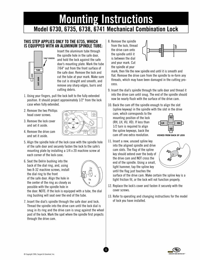
THIS STEP APPLIES ONLY TO THE 6735, WHICH IS EQUIPPED WITH AN ALUMINUM SPINDLE TUBE:
Insert the aluminum tube through the spindle hole in the safe door, and hold the lock against the safe door’s mounting plate. Mark the tube 7/64" out from the front surface of the safe door. Remove the lock and cut the tube at your mark. Make sure the cut is straight and smooth, and remove any sharp edges, burrs and cutting debris.
1. Using your fingers, pull the lock bolt to the fully extended position. It should project approximately 1/2" from the lock case when fully extended.
2. Remove the two Phillips head cover screws.
3. Remove the lock cover and set it aside.
4. Remove the drive cam and set it aside.
5. Align the spindle hole of the lock case with the spindle hole of the safe door and securely fasten the lock to the safe’s mounting plate by installing a 1/4 x 20 machine screw at each corner of the lock case.
6. Seat the Delrin bushing into the back of the dial ring, and, using two 8-32 machine screws, install the dial ring to the front of the safe door. Align the hole in the center of the ring as closely as possible with the spindle hole in the door. NOTE: If the lock is equipped with a tube, the dial ring bushing will seat over the end of the tube.
7. Insert the dial’s spindle through the safe door and lock. Thread the spindle into the drive cam until the lock dial is snug in its ring and the drive cam is snug against the wheel post of the lock. Mark the spot where the spindle first projects through the drive cam.
8. Remove the spindle from the lock, thread the drive cam onto the spindle until it is between the dial and your mark. Cut the spindle at your mark, then file the new spindle end until it is smooth and flat. Remove the drive cam from the spindle to re-form any threads, which may have been damaged in the cutting pro-cess.
9. Insert the dial’s spindle through the safe door and thread it into the drive cam until snug. The end of the spindle should now be nearly flush with the surface of the drive cam.
10. Back the cam off the spindle enough to align the slot (spline keyway) in the spindle with the slot in the drive cam, which corresponds to the mounting position of the lock (RH, LH, VU, VD). If less than 1/2 turn is required to align the spline keyways, back the cam off one extra revolution.
11. Insert a new, unused spline key into the aligned spindle and drive cam slots. The flag of the spline key should extend over the body of the drive cam and NOT cross the end of the spindle. Using a small, light hammer, tap the spline key until the flag just touches the surface of the drive cam. Make certain the spline key is a tight friction fit, or the lock will not function properly.
12. Replace the lock’s cover and fasten it securely with the cover screws.
13. Refer to operating and changing instructions for the model of lock you have installed.
Model 6730, 6735, 6738, 6741 Mechanical Combination LockMounting Instructions
2© Copyright 2006, Sargent & Greenleaf, Inc.
READ THESE INSTRUCTIONS THOROUGHLY BEFORE OPERATING THE LOCK OR ATTEMPTING TO CHANGE THE COMBINATIONSNote: To assure proper operation, all combination safe locks should be serviced by a qualified safe technician annually; more often if used in a hostile environment (dust, dirt, high humidity, etc.).
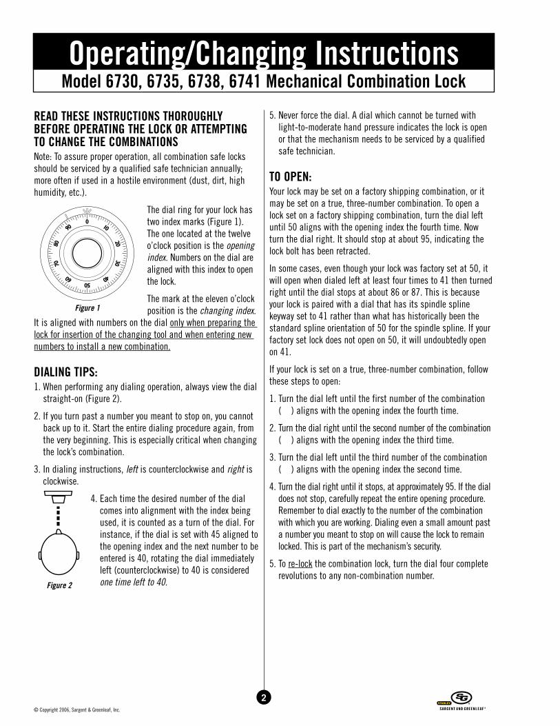
The dial ring for your lock has two index marks (Figure 1). The one located at the twelve o’clock position is the opening index. Numbers on the dial are aligned with this index to open the lock.
The mark at the eleven o’clock position is the changing index.
It is aligned with numbers on the dial only when preparing the lock for insertion of the changing tool and when entering new numbers to install a new combination.
DIALING TIPS: 1. When performing any dialing operation, always view the dial
straight-on (Figure 2).
2. If you turn past a number you meant to stop on, you cannot back up to it. Start the entire dialing procedure again, from the very beginning. This is especially critical when changing the lock’s combination.
3. In dialing instructions, left is counterclockwise and right is clockwise.
4. Each time the desired number of the dial comes into alignment with the index being used, it is counted as a turn of the dial. For instance, if the dial is set with 45 aligned to the opening index and the next number to be entered is 40, rotating the dial immediately left (counterclockwise) to 40 is considered one time left to 40.
5. Never force the dial. A dial which cannot be turned with light-to-moderate hand pressure indicates the lock is open or that the mechanism needs to be serviced by a qualified safe technician.
TO OPEN: Your lock may be set on a factory shipping combination, or it may be set on a true, three-number combination. To open a lock set on a factory shipping combination, turn the dial left until 50 aligns with the opening index the fourth time. Now turn the dial right. It should stop at about 95, indicating the lock bolt has been retracted.
In some cases, even though your lock was factory set at 50, it will open when dialed left at least four times to 41 then turned right until the dial stops at about 86 or 87. This is because your lock is paired with a dial that has its spindle spline keyway set to 41 rather than what has historically been the standard spline orientation of 50 for the spindle spline. If your factory set lock does not open on 50, it will undoubtedly open on 41.
If your lock is set on a true, three-number combination, follow these steps to open:
1. Turn the dial left until the first number of the combination ( ) aligns with the opening index the fourth time.
2. Turn the dial right until the second number of the combination ( ) aligns with the opening index the third time.
3. Turn the dial left until the third number of the combination ( ) aligns with the opening index the second time.
4. Turn the dial right until it stops, at approximately 95. If the dial does not stop, carefully repeat the entire opening procedure. Remember to dial exactly to the number of the combination with which you are working. Dialing even a small amount past a number you meant to stop on will cause the lock to remain locked. This is part of the mechanism’s security.
5. To re-lock the combination lock, turn the dial four complete revolutions to any non-combination number.
Model 6730, 6735, 6738, 6741 Mechanical Combination LockOperating/Changing Instructions
Figure 2
Figure 1
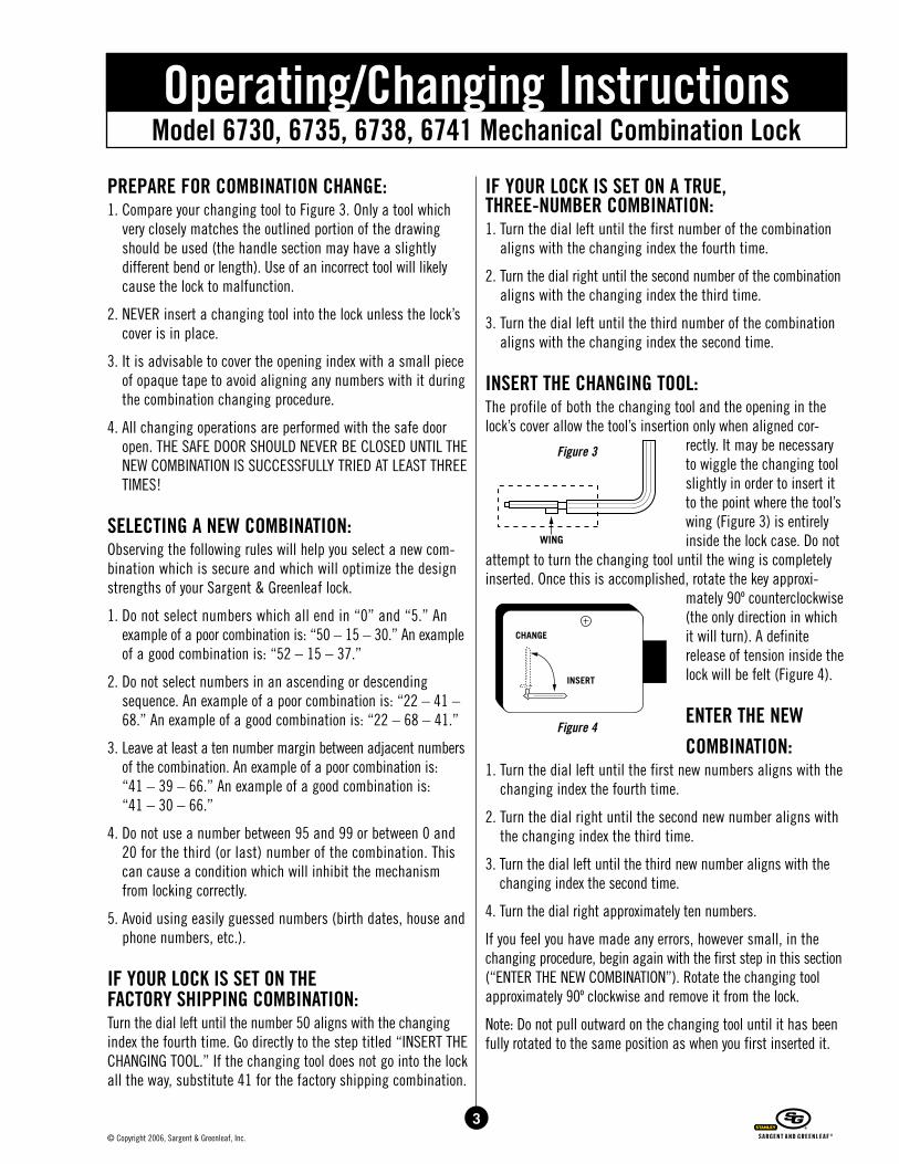
PREPARE FOR COMBINATION CHANGE: 1. Compare your changing tool to Figure 3. Only a tool which
very closely matches the outlined portion of the drawing should be used (the handle section may have a slightly different bend or length). Use of an incorrect tool will likely cause the lock to malfunction.
2. NEVER insert a changing tool into the lock unless the lock’s cover is in place.
3. It is advisable to cover the opening index with a small piece of opaque tape to avoid aligning any numbers with it during the combination changing procedure.
4. All changing operations are performed with the safe door open. THE SAFE DOOR SHOULD NEVER BE CLOSED UNTIL THE NEW COMBINATION IS SUCCESSFULLY TRIED AT LEAST THREE TIMES!
SELECTING A NEW COMBINATION: Observing the following rules will help you select a new com-bination which is secure and which will optimize the design strengths of your Sargent & Greenleaf lock.
1. Do not select numbers which all end in “0” and “5.” An example of a poor combination is: “50 – 15 – 30.” An example of a good combination is: “52 – 15 – 37.”
2. Do not select numbers in an ascending or descending sequence. An example of a poor combination is: “22 – 41 – 68.” An example of a good combination is: “22 – 68 – 41.”
3. Leave at least a ten number margin between adjacent numbers of the combination. An example of a poor combination is: “41 – 39 – 66.” An example of a good combination is: “41 – 30 – 66.”
4. Do not use a number between 95 and 99 or between 0 and 20 for the third (or last) number of the combination. This can cause a condition which will inhibit the mechanism from locking correctly.
5. Avoid using easily guessed numbers (birth dates, house and phone numbers, etc.).
IF YOUR LOCK IS SET ON THE FACTORY SHIPPING COMBINATION: Turn the dial left until the number 50 aligns with the changing index the fourth time. Go directly to the step titled “INSERT THE CHANGING TOOL.” If the changing tool does not go into the lock all the way, substitute 41 for the factory shipping combination.
IF YOUR LOCK IS SET ON A TRUE, THREE-NUMBER COMBINATION: 1. Turn the dial left until the first number of the combination
aligns with the changing index the fourth time.
2. Turn the dial right until the second number of the combination aligns with the changing index the third time.
3. Turn the dial left until the third number of the combination aligns with the changing index the second time.
INSERT THE CHANGING TOOL: The profile of both the changing tool and the opening in the lock’s cover allow the tool’s insertion only when aligned cor-
rectly. It may be necessary to wiggle the changing tool slightly in order to insert it to the point where the tool’s wing (Figure 3) is entirely inside the lock case. Do not
attempt to turn the changing tool until the wing is completely inserted. Once this is accomplished, rotate the key approxi-
mately 90º counterclockwise (the only direction in which it will turn). A definite release of tension inside the lock will be felt (Figure 4).
ENTER THE NEW COMBINATION:
1. Turn the dial left until the first new numbers aligns with the changing index the fourth time.
2. Turn the dial right until the second new number aligns with the changing index the third time.
3. Turn the dial left until the third new number aligns with the changing index the second time.
4. Turn the dial right approximately ten numbers.
If you feel you have made any errors, however small, in the changing procedure, begin again with the first step in this section (“ENTER THE NEW COMBINATION”). Rotate the changing tool approximately 90º clockwise and remove it from the lock.
Note: Do not pull outward on the changing tool until it has been fully rotated to the same position as when you first inserted it.
Model 6730, 6735, 6738, 6741 Mechanical Combination LockOperating/Changing Instructions
Figure 3
Figure 4
3© Copyright 2006, Sargent & Greenleaf, Inc.
4© Copyright 2006, Sargent & Greenleaf, Inc.
CHECK THE NEW COMBINATION: Uncover the opening index and check your new combination by following these instructions, which are identical to those under “TO OPEN.”
1. Turn the dial left until the first number of the new combina-tion aligns with the opening index the fourth time.
2. Turn the dial right until the second number of the new com-bination aligns with the opening index the third time.
3. Turn the dial left until the third number of the new combina-tion aligns with the opening index the second time.
4. Turn the dial right. It should come to a positive stop in less than one revolution. If the dial does not stop, carefully repeat the entire opening procedure at least two more times before either calling a qualified safe technician or referring to the “…in case of trouble” section.
5. A combination change should be considered successful only when the new combination is successfully tried at least three times. Only then is it wise to close and lock the safe door.
…in case of trouble Anyone can make mistakes and “lose” a lock’s combination in the process of changing to a new set of numbers. This section will detail two steps you can take on your own to manually pre-pare the lock for a second attempt to enter a new combination. If you still cannot set a combination into the lock by following these procedures, call a reputable safe technician to correct the problem and service the lock. DO NOT CLOSE THE SAFE DOOR BEFORE THIS SERVICE IS PERFORMED.
PROCEDURE #1: If the lock will not open when the new combination is dialed to the opening index, cover the opening index and dial the new numbers to the changing index. For example:
1. Turn the dial left until the first new number aligns with the changing index the fourth time.
2. Turn the dial right until the second new number aligns with the changing index the third time.
3. Turn the dial left until the third new number aligns with the changing index the second time.
Once this is done, attempt to re-insert the changing tool into the lock. Although it’s acceptable to wiggle the tool slightly, do not force it. If the key will enter the mechanism to the point where the wing is entirely inside the lock case, you may turn
the changing tool approximately 90º counterclockwise and proceed with the steps listed under “ENTER THE NEW COMBINATION.”
PROCEDURE #2: These steps should only be taken after unsuccessfully trying Procedure #1 and inspecting the area of the lock for attach-ments to the lock case. If any part of the safe is attached to or bears against any part of the lock’s cover, refer servicing to a qualified technician and do NOT proceed.
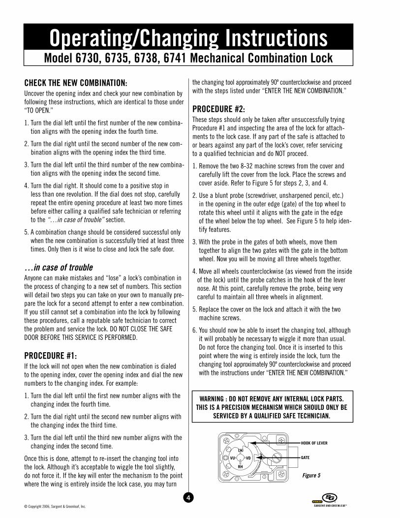
1. Remove the two 8-32 machine screws from the cover and carefully lift the cover from the lock. Place the screws and cover aside. Refer to Figure 5 for steps 2, 3, and 4.
2. Use a blunt probe (screwdriver, unsharpened pencil, etc.) in the opening in the outer edge (gate) of the top wheel to rotate this wheel until it aligns with the gate in the edge of the wheel below the top wheel. See Figure 5 to help iden-tify features.
3. With the probe in the gates of both wheels, move them together to align the two gates with the gate in the bottom wheel. Now you will be moving all three wheels together.
4. Move all wheels counterclockwise (as viewed from the inside of the lock) until the probe catches in the hook of the lever nose. At this point, carefully remove the probe, being very careful to maintain all three wheels in alignment.
5. Replace the cover on the lock and attach it with the two machine screws.
6. You should now be able to insert the changing tool, although it will probably be necessary to wiggle it more than usual. Do not force the changing tool. Once it is inserted to this point where the wing is entirely inside the lock, turn the changing tool approximately 90º counterclockwise and proceed with the instructions under “ENTER THE NEW COMBINATION.”
WARNING : DO NOT REMOVE ANY INTERNAL LOCK PARTS. THIS IS A PRECISION MECHANISM WHICH SHOULD ONLY BE
SERVICED BY A QUALIFIED SAFE TECHNICIAN.
Model 6730, 6735, 6738, 6741 Mechanical Combination LockOperating/Changing Instructions
Figure 5
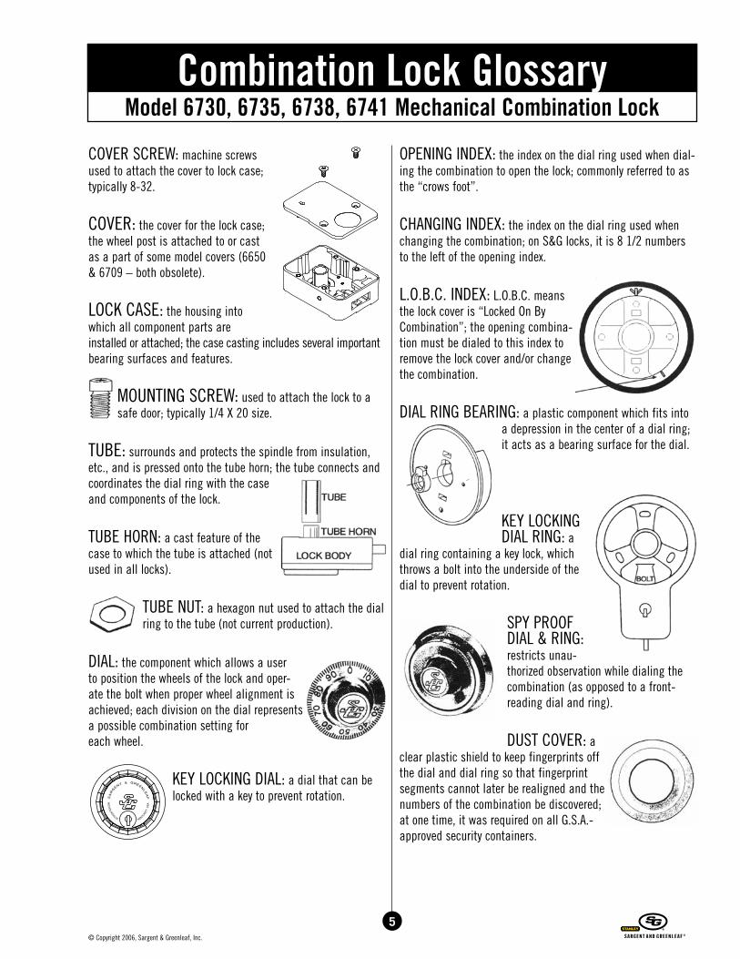
COVER SCREW: machine screws used to attach the cover to lock case; typically 8-32.
COVER: the cover for the lock case; the wheel post is attached to or cast as a part of some model covers (6650 & 6709 – both obsolete).
LOCK CASE: the housing into which all component parts are installed or attached; the case casting includes several important bearing surfaces and features.
MOUNTING SCREW: used to attach the lock to a safe door; typically 1/4 X 20 size.
TUBE: surrounds and protects the spindle from insulation, etc., and is pressed onto the tube horn; the tube connects and coordinates the dial ring with the case and components of the lock.
TUBE HORN: a cast feature of the case to which the tube is attached (not used in all locks).
TUBE NUT: a hexagon nut used to attach the dial ring to the tube (not current production).
DIAL: the component which allows a user to position the wheels of the lock and oper-ate the bolt when proper wheel alignment is achieved; each division on the dial represents a possible combination setting for each wheel.
KEY LOCKING DIAL: a dial that can be locked with a key to prevent rotation.
OPENING INDEX: the index on the dial ring used when dial-ing the combination to open the lock; commonly referred to as the “crows foot”.
CHANGING INDEX: the index on the dial ring used when changing the combination; on S&G locks, it is 8 1/2 numbers to the left of the opening index.
L.O.B.C. INDEX: L.O.B.C. means the lock cover is “Locked On By Combination”; the opening combina-tion must be dialed to this index to remove the lock cover and/or change the combination.
DIAL RING BEARING: a plastic component which fits into a depression in the center of a dial ring; it acts as a bearing surface for the dial.
KEY LOCKING DIAL RING: a
dial ring containing a key lock, which throws a bolt into the underside of the dial to prevent rotation.
SPY PROOF DIAL & RING: restricts unau-thorized observation while dialing the combination (as opposed to a front-reading dial and ring).
DUST COVER: a clear plastic shield to keep fingerprints off the dial and dial ring so that fingerprint segments cannot later be realigned and the numbers of the combination be discovered; at one time, it was required on all G.S.A.-approved security containers.
Model 6730, 6735, 6738, 6741 Mechanical Combination LockCombination Lock Glossary
�
5© Copyright 2006, Sargent & Greenleaf, Inc.
6© Copyright 2006, Sargent & Greenleaf, Inc.
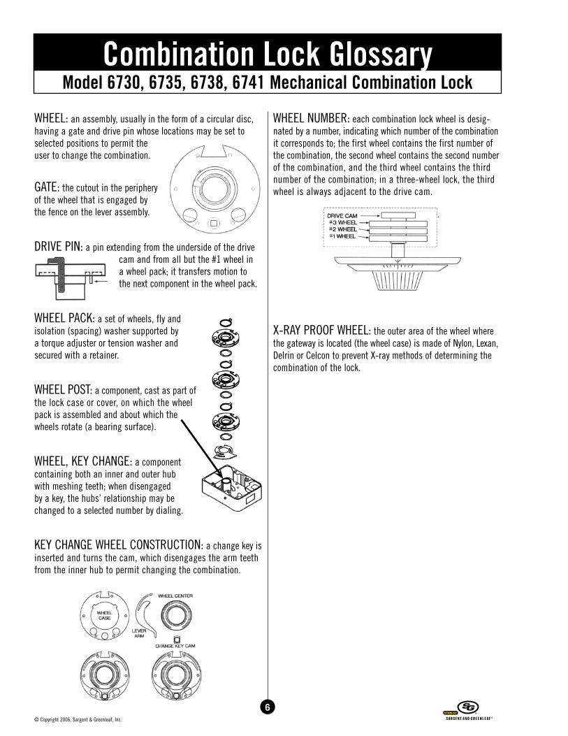
WHEEL: an assembly, usually in the form of a circular disc, having a gate and drive pin whose locations may be set to selected positions to permit the user to change the combination.
GATE: the cutout in the periphery of the wheel that is engaged by the fence on the lever assembly.
DRIVE PIN: a pin extending from the underside of the drive cam and from all but the #1 wheel in a wheel pack; it transfers motion to the next component in the wheel pack.
WHEEL PACK: a set of wheels, fly andisolation (spacing) washer supported by a torque adjuster or tension washer and secured with a retainer.
WHEEL POST: a component, cast as part of the lock case or cover, on which the wheel pack is assembled and about which the wheels rotate (a bearing surface).
WHEEL, KEY CHANGE: a component containing both an inner and outer hub with meshing teeth; when disengaged by a key, the hubs’ relationship may be changed to a selected number by dialing.
KEY CHANGE WHEEL CONSTRUCTION: a change key is inserted and turns the cam, which disengages the arm teeth from the inner hub to permit changing the combination.
WHEEL NUMBER: each combination lock wheel is desig-nated by a number, indicating which number of the combination it corresponds to; the first wheel contains the first number of the combination, the second wheel contains the second number of the combination, and the third wheel contains the third number of the combination; in a three-wheel lock, the third wheel is always adjacent to the drive cam.
X-RAY PROOF WHEEL: the outer area of the wheel where the gateway is located (the wheel case) is made of Nylon, Lexan, Delrin or Celcon to prevent X-ray methods of determining the combination of the lock.
Model 6730, 6735, 6738, 6741 Mechanical Combination LockCombination Lock Glossary
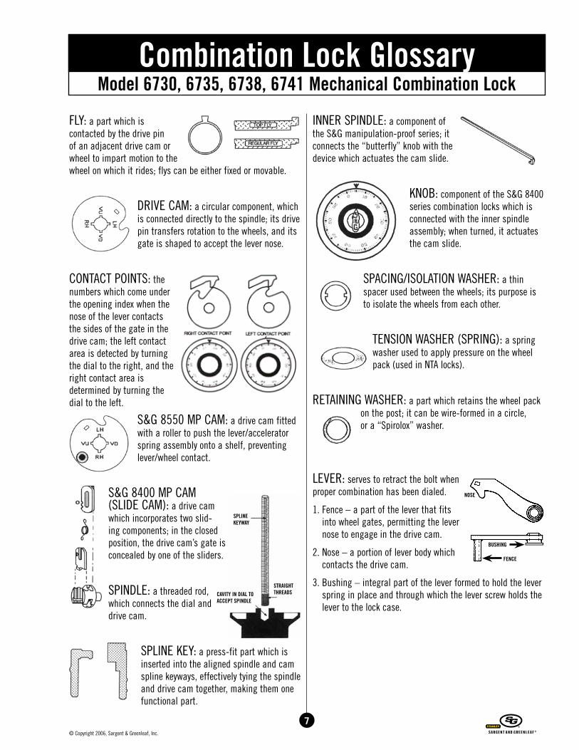
FLY: a part which is contacted by the drive pin of an adjacent drive cam or wheel to impart motion to the wheel on which it rides; flys can be either fixed or movable.
DRIVE CAM: a circular component, which is connected directly to the spindle; its drive pin transfers rotation to the wheels, and its gate is shaped to accept the lever nose.
CONTACT POINTS: the numbers which come under the opening index when the nose of the lever contacts the sides of the gate in the drive cam; the left contact area is detected by turning the dial to the right, and the right contact area is determined by turning the dial to the left.
S&G 8550 MP CAM: a drive cam fitted with a roller to push the lever/accelerator spring assembly onto a shelf, preventing lever/wheel contact.
S&G 8400 MP CAM (SLIDE CAM): a drive cam which incorporates two slid-ing components; in the closed position, the drive cam’s gate is concealed by one of the sliders.
SPINDLE: a threaded rod, which connects the dial and drive cam.
SPLINE KEY: a press-fit part which is inserted into the aligned spindle and cam spline keyways, effectively tying the spindle and drive cam together, making them one functional part.
INNER SPINDLE: a component of the S&G manipulation-proof series; it connects the “butterfly” knob with the device which actuates the cam slide.
KNOB: component of the S&G 8400 series combination locks which is connected with the inner spindle assembly; when turned, it actuates the cam slide.
SPACING/ISOLATION WASHER: a thin spacer used between the wheels; its purpose is to isolate the wheels from each other.
TENSION WASHER (SPRING): a spring washer used to apply pressure on the wheel pack (used in NTA locks).
RETAINING WASHER: a part which retains the wheel pack on the post; it can be wire-formed in a circle, or a “Spirolox” washer.
LEVER: serves to retract the bolt when proper combination has been dialed.
1. Fence – a part of the lever that fits into wheel gates, permitting the lever nose to engage in the drive cam.
2. Nose – a portion of lever body which contacts the drive cam.
3. Bushing – integral part of the lever formed to hold the lever spring in place and through which the lever screw holds the lever to the lock case.
Model 6730, 6735, 6738, 6741 Mechanical Combination LockCombination Lock Glossary
SPLINE KEYWAY
STRAIGHTTHREADSCAVITY IN DIAL TO
ACCEPT SPINDLE
NOSE
BUSHING
FENCE
7© Copyright 2006, Sargent & Greenleaf, Inc.
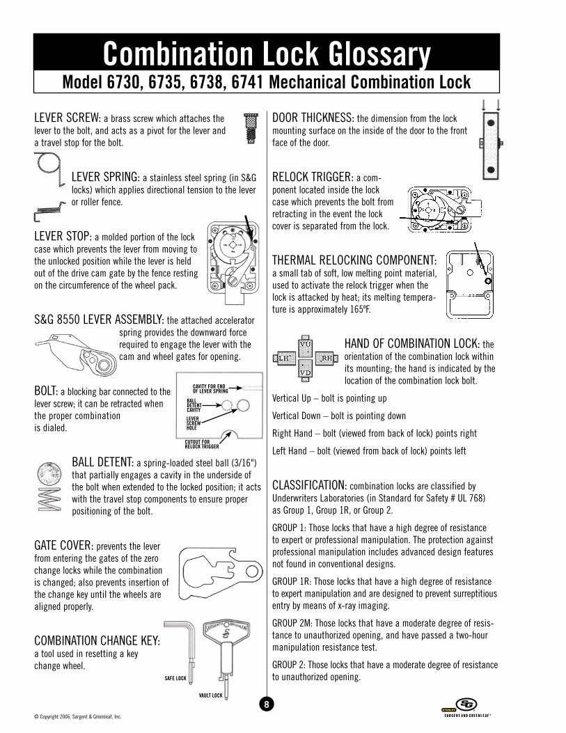
LEVER SCREW: a brass screw which attaches the lever to the bolt, and acts as a pivot for the lever and a travel stop for the bolt.
LEVER SPRING: a stainless steel spring (in S&G locks) which applies directional tension to the lever or roller fence.
LEVER STOP: a molded portion of the lock case which prevents the lever from moving to the unlocked position while the lever is held out of the drive cam gate by the fence resting on the circumference of the wheel pack.
S&G 8550 LEVER ASSEMBLY: the attached accelerator spring provides the downward force required to engage the lever with the cam and wheel gates for opening.
BOLT: a blocking bar connected to the lever screw; it can be retracted when the proper combination is dialed.
BALL DETENT: a spring-loaded steel ball (3/16") that partially engages a cavity in the underside of the bolt when extended to the locked position; it acts with the travel stop components to ensure proper positioning of the bolt.
GATE COVER: prevents the lever from entering the gates of the zero change locks while the combination is changed; also prevents insertion of the change key until the wheels are aligned properly.
COMBINATION CHANGE KEY: a tool used in resetting a key change wheel.
DOOR THICKNESS: the dimension from the lock mounting surface on the inside of the door to the front face of the door.
RELOCK TRIGGER: a com-ponent located inside the lock case which prevents the bolt from retracting in the event the lock cover is separated from the lock.
THERMAL RELOCKING COMPONENT: a small tab of soft, low melting point material, used to activate the relock trigger when the lock is attacked by heat; its melting tempera-ture is approximately 165ºF.
HAND OF COMBINATION LOCK: the orientation of the combination lock within its mounting; the hand is indicated by the location of the combination lock bolt.
Vertical Up – bolt is pointing up
Vertical Down – bolt is pointing down
Right Hand – bolt (viewed from back of lock) points right
Left Hand – bolt (viewed from back of lock) points left
CLASSIFICATION: combination locks are classified by Underwriters Laboratories (in Standard for Safety # UL 768) as Group 1, Group 1R, or Group 2.
GROUP 1: Those locks that have a high degree of resistance to expert or professional manipulation. The protection against professional manipulation includes advanced design features not found in conventional designs.
GROUP 1R: Those locks that have a high degree of resistance to expert manipulation and are designed to prevent surreptitious entry by means of x-ray imaging.
GROUP 2M: Those locks that have a moderate degree of resis-tance to unauthorized opening, and have passed a two-hour manipulation resistance test.
GROUP 2: Those locks that have a moderate degree of resistance to unauthorized opening.
LEVERSCREWHOLE
BALLDETENTCAVITY
CAVITY FOR ENDOF LEVER SPRING
CUTOUT FORRELOCK TRIGGER
8© Copyright 2006, Sargent & Greenleaf, Inc.
Model 6730, 6735, 6738, 6741 Mechanical Combination LockCombination Lock Glossary
SAFE LOCK
VAULT LOCK
Model 6730, 6735, 6738, 6741 Mechanical Combination LockTroubleshooting/Dialing Diagnostics
A guide to solving safe lockouts through knowledge, rather than force
Lockout Diagnostics
Between 80 and 90% of all safe lockouts can be overcome without the need to penetrate a safe. A combination lock is a finely tuned mechanical puzzle whose answer is known only to those who possess the combination and can use it to correctly and precisely align internal parts of the lock. Unfortunately, even the tiniest misalignment of components can (and often does) change the answer to the puzzle, or simply make the puzzle more difficult to solve.
ProPer DiaLing technique
A very high percentage of lockouts are due to the end user’s improper dialing of the combination lock. There is a simple, definite procedure which must be followed to achieve consis-tent success. An important point to remember is that there are usually two index lines on a dial ring. The one at the twelve o’clock position is used in dialing open the lock. The mark at the eleven o’clock position (if present) is used only for chang-ing the combination.
While performing any procedure involving dialing numbers into the lock, it is important to view the dial and ring straight on. This helps ensure the number you are entering will be aligned directly under the index mark. If you dial past the intended number even slightly, begin the entire dialing procedure again.
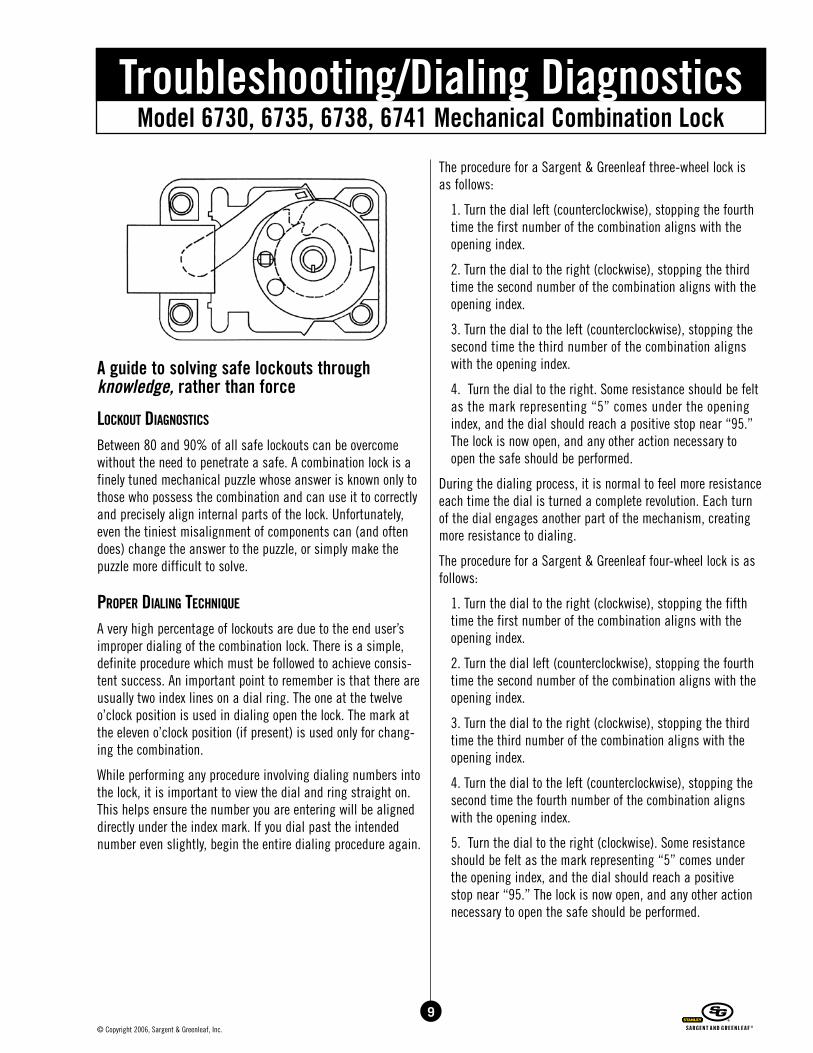
The procedure for a Sargent & Greenleaf three-wheel lock is as follows:
1. Turn the dial left (counterclockwise), stopping the fourth time the first number of the combination aligns with the opening index.
2. Turn the dial to the right (clockwise), stopping the third time the second number of the combination aligns with the opening index.
3. Turn the dial to the left (counterclockwise), stopping the second time the third number of the combination aligns with the opening index.
4. Turn the dial to the right. Some resistance should be felt as the mark representing “5” comes under the opening index, and the dial should reach a positive stop near “95.” The lock is now open, and any other action necessary to open the safe should be performed.
During the dialing process, it is normal to feel more resistance each time the dial is turned a complete revolution. Each turn of the dial engages another part of the mechanism, creating more resistance to dialing.
The procedure for a Sargent & Greenleaf four-wheel lock is as follows:
1. Turn the dial to the right (clockwise), stopping the fifth time the first number of the combination aligns with the opening index.
2. Turn the dial left (counterclockwise), stopping the fourth time the second number of the combination aligns with the opening index.
3. Turn the dial to the right (clockwise), stopping the third time the third number of the combination aligns with the opening index.
4. Turn the dial to the left (counterclockwise), stopping the second time the fourth number of the combination aligns with the opening index.
5. Turn the dial to the right (clockwise). Some resistance should be felt as the mark representing “5” comes under the opening index, and the dial should reach a positive stop near “95.” The lock is now open, and any other action necessary to open the safe should be performed.
9© Copyright 2006, Sargent & Greenleaf, Inc.
10© Copyright 2006, Sargent & Greenleaf, Inc.
Model 6730, 6735, 6738, 6741 Mechanical Combination LockTroubleshooting/Dialing Diagnostics
MisaLigneD DiaL ring
The number one cause of lockouts is a misaligned dial ring. The ring provides a critical bearing surface for the dial, and the two parts must be aligned correctly. The ring has two elongated screw holes for attachment to the safe door. The elongated holes allow the safe manufacturer to make the best possible alignment of parts. The negative aspect of the elongated screw holes is illustrated when the ring or dial is bumped, and is allowed to move within the limits of the mounting screw holes. The surest way to prevent movement of the dial ring is to install the ring using the screws in the elongated holes, check for smooth operation of the dial, then remove the dial and insert a pin or machine screw through one of the two circular screw holes in the ring. A hole will need to be placed in the safe door to accommodate the additional fastener.
Let’s assume this extra step was not taken, and the dial has shifted from its original position. This situation can manifest itself in two ways. The following symptoms can occur sepa-rately or together.
BinDing DiaL
The dial binds against the ring constantly or in one or more areas as the dial is turned. This problem is easy to correct. You will notice that the dial doesn’t sit squarely in its ring when viewed from top, bottom or one of the sides. In certain dial/ring configurations, you may notice a larger gap between the two components at some spot on the dial. Use a light plastic or rawhide mallet (or even a screwdriver handle) to tap the dial ring directly adjacent to the point where the dial rides lower in the ring, or adjacent to the widest gap between the dial and ring. Tap lightly, and NEVER strike the dial, only the ring. Adjust the position, check for smoothness of dial movement, and make further adjustments as necessary. If a high spot or gap isn’t apparent, just tap lightly around the circumference of the ring until the dial rotates smoothly.
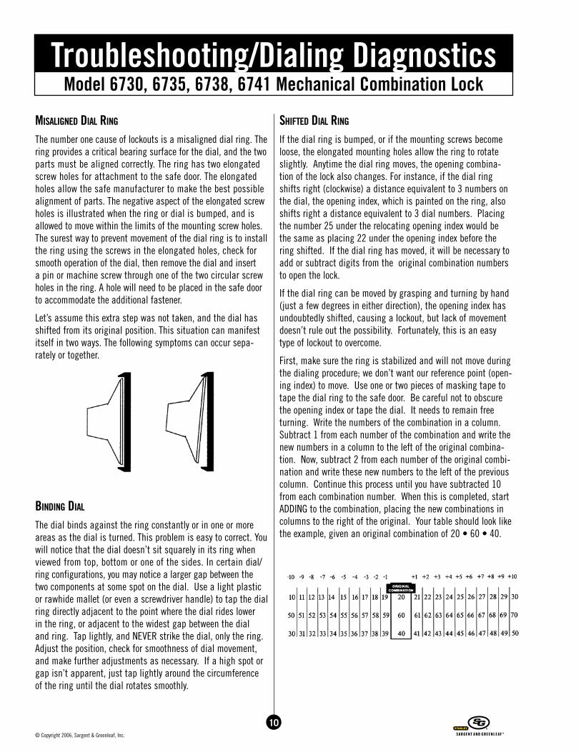
shifteD DiaL ring
If the dial ring is bumped, or if the mounting screws become loose, the elongated mounting holes allow the ring to rotate slightly. Anytime the dial ring moves, the opening combina-tion of the lock also changes. For instance, if the dial ring shifts right (clockwise) a distance equivalent to 3 numbers on the dial, the opening index, which is painted on the ring, also shifts right a distance equivalent to 3 dial numbers. Placing the number 25 under the relocating opening index would be the same as placing 22 under the opening index before the ring shifted. If the dial ring has moved, it will be necessary to add or subtract digits from the original combination numbers to open the lock.
If the dial ring can be moved by grasping and turning by hand (just a few degrees in either direction), the opening index has undoubtedly shifted, causing a lockout, but lack of movement doesn’t rule out the possibility. Fortunately, this is an easy type of lockout to overcome.
First, make sure the ring is stabilized and will not move during the dialing procedure; we don’t want our reference point (open-ing index) to move. Use one or two pieces of masking tape to tape the dial ring to the safe door. Be careful not to obscure the opening index or tape the dial. It needs to remain free turning. Write the numbers of the combination in a column. Subtract 1 from each number of the combination and write the new numbers in a column to the left of the original combina-tion. Now, subtract 2 from each number of the original combi-nation and write these new numbers to the left of the previous column. Continue this process until you have subtracted 10 from each combination number. When this is completed, start ADDING to the combination, placing the new combinations in columns to the right of the original. Your table should look like the example, given an original combination of 20 • 60 • 40.
Model 6730, 6735, 6738, 6741 Mechanical Combination LockTroubleshooting/Dialing Diagnostics
stuck fLy
So far, we’ve only checked and corrected problems with external parts: the dial and ring. There are many more parts inside the lock which are required to work with much greater precision.
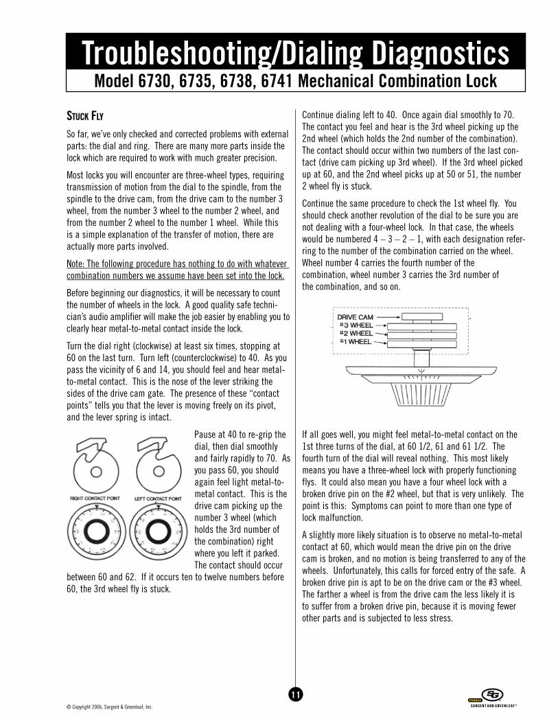
Most locks you will encounter are three-wheel types, requiring transmission of motion from the dial to the spindle, from the spindle to the drive cam, from the drive cam to the number 3 wheel, from the number 3 wheel to the number 2 wheel, and from the number 2 wheel to the number 1 wheel. While this is a simple explanation of the transfer of motion, there are actually more parts involved.
Note: The following procedure has nothing to do with whatever combination numbers we assume have been set into the lock.
Before beginning our diagnostics, it will be necessary to count the number of wheels in the lock. A good quality safe techni-cian’s audio amplifier will make the job easier by enabling you to clearly hear metal-to-metal contact inside the lock.
Turn the dial right (clockwise) at least six times, stopping at 60 on the last turn. Turn left (counterclockwise) to 40. As you pass the vicinity of 6 and 14, you should feel and hear metal-to-metal contact. This is the nose of the lever striking the sides of the drive cam gate. The presence of these “contact points” tells you that the lever is moving freely on its pivot, and the lever spring is intact.
Pause at 40 to re-grip the dial, then dial smoothly and fairly rapidly to 70. As you pass 60, you should again feel light metal-to-metal contact. This is the drive cam picking up the number 3 wheel (which holds the 3rd number of the combination) right where you left it parked. The contact should occur
between 60 and 62. If it occurs ten to twelve numbers before 60, the 3rd wheel fly is stuck.
Continue dialing left to 40. Once again dial smoothly to 70. The contact you feel and hear is the 3rd wheel picking up the 2nd wheel (which holds the 2nd number of the combination). The contact should occur within two numbers of the last con-tact (drive cam picking up 3rd wheel). If the 3rd wheel picked up at 60, and the 2nd wheel picks up at 50 or 51, the number 2 wheel fly is stuck.
Continue the same procedure to check the 1st wheel fly. You should check another revolution of the dial to be sure you are not dealing with a four-wheel lock. In that case, the wheels would be numbered 4 – 3 – 2 – 1, with each designation refer-ring to the number of the combination carried on the wheel. Wheel number 4 carries the fourth number of the combination, wheel number 3 carries the 3rd number of the combination, and so on.
If all goes well, you might feel metal-to-metal contact on the 1st three turns of the dial, at 60 1/2, 61 and 61 1/2. The fourth turn of the dial will reveal nothing. This most likely means you have a three-wheel lock with properly functioning flys. It could also mean you have a four wheel lock with a broken drive pin on the #2 wheel, but that is very unlikely. The point is this: Symptoms can point to more than one type of lock malfunction.
A slightly more likely situation is to observe no metal-to-metal contact at 60, which would mean the drive pin on the drive cam is broken, and no motion is being transferred to any of the wheels. Unfortunately, this calls for forced entry of the safe. A broken drive pin is apt to be on the drive cam or the #3 wheel. The farther a wheel is from the drive cam the less likely it is to suffer from a broken drive pin, because it is moving fewer other parts and is subjected to less stress.
11© Copyright 2006, Sargent & Greenleaf, Inc.
12© Copyright 2006, Sargent & Greenleaf, Inc.
Model 6730, 6735, 6738, 6741 Mechanical Combination LockTroubleshooting/Dialing Diagnostics
a fLy in the ointMent
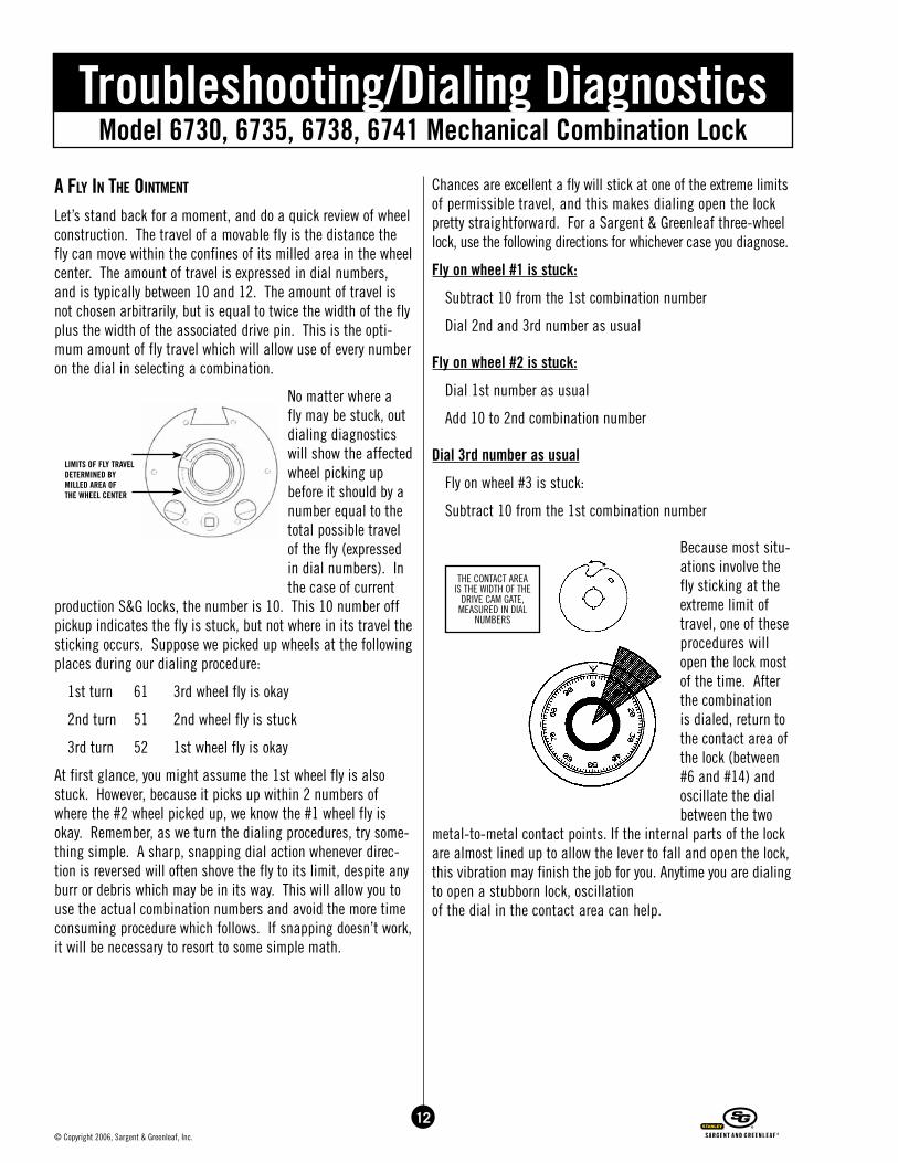
Let’s stand back for a moment, and do a quick review of wheel construction. The travel of a movable fly is the distance the fly can move within the confines of its milled area in the wheel center. The amount of travel is expressed in dial numbers, and is typically between 10 and 12. The amount of travel is not chosen arbitrarily, but is equal to twice the width of the fly plus the width of the associated drive pin. This is the opti-mum amount of fly travel which will allow use of every number on the dial in selecting a combination.
No matter where a fly may be stuck, out dialing diagnostics will show the affected wheel picking up before it should by a number equal to the total possible travel of the fly (expressed in dial numbers). In the case of current
production S&G locks, the number is 10. This 10 number off pickup indicates the fly is stuck, but not where in its travel the sticking occurs. Suppose we picked up wheels at the following places during our dialing procedure:
1st turn 61 3rd wheel fly is okay
2nd turn 51 2nd wheel fly is stuck
3rd turn 52 1st wheel fly is okay
At first glance, you might assume the 1st wheel fly is also stuck. However, because it picks up within 2 numbers of where the #2 wheel picked up, we know the #1 wheel fly is okay. Remember, as we turn the dialing procedures, try some-thing simple. A sharp, snapping dial action whenever direc-tion is reversed will often shove the fly to its limit, despite any burr or debris which may be in its way. This will allow you to use the actual combination numbers and avoid the more time consuming procedure which follows. If snapping doesn’t work, it will be necessary to resort to some simple math.
Chances are excellent a fly will stick at one of the extreme limits of permissible travel, and this makes dialing open the lock pretty straightforward. For a Sargent & Greenleaf three-wheel lock, use the following directions for whichever case you diagnose.
Fly on wheel #1 is stuck:
Subtract 10 from the 1st combination number
Dial 2nd and 3rd number as usual
Fly on wheel #2 is stuck:
Dial 1st number as usual
Add 10 to 2nd combination number
Dial 3rd number as usual
Fly on wheel #3 is stuck:
Subtract 10 from the 1st combination number
Because most situ-ations involve the fly sticking at the extreme limit of travel, one of these procedures will open the lock most of the time. After the combination is dialed, return to the contact area of the lock (between #6 and #14) and oscillate the dial between the two
metal-to-metal contact points. If the internal parts of the lock are almost lined up to allow the lever to fall and open the lock, this vibration may finish the job for you. Anytime you are dialing to open a stubborn lock, oscillation of the dial in the contact area can help.
LIMITS OF FLY TRAVELDETERMINED BY MILLED AREA OF THE WHEEL CENTER
THE CONTACT AREA IS THE WIDTH OF THE
DRIVE CAM GATE, MEASURED IN DIAL
NUMBERS
Model 6730, 6735, 6738, 6741 Mechanical Combination LockTroubleshooting/Dialing Diagnostics
We add or subtract 10 from combination numbers because this is the distance the fly can normally move in an S&G lock. Unless you can absolutely determine that 10 is the magic number for the lock you are working on, the following instructions might be of more use.
Fly on wheel #1 is stuck:
Subtract “X” from the 1st combination number
Dial 2nd and 3rd number as usual
Fly on wheel #2 is stuck:
Dial 1st number as usual
Add “X” to the 2nd combination number
Dial 3rd number as usual
Fly on 3rd wheel is stuck
Subtract “X” from the 1st combination number
Dial the 2nd number as usual
Subtract “X” from the 3rd combination number
Select the appropriate dialing directions for the situation you have diagnosed. For the 1st dialing procedure, X=8. Dial the same procedure with X=9, then X=10, then X=11, then X=12. One of these five values of X is likely to work.
The worst possible case is a fly stuck somewhere between the permissible limits of its normal travel. Our diagnostics point out which wheel contains the sticking fly and tell us the total effect on this wheel and the next one down the transmission path is 10. Remember, 10 is the total permissible range of fly travel in our S&G lock. In case we forget, our dialing reveals a 10 number difference in pickup points between a “healthy” wheel and a sticky one.
If the fly is stuck on the #1 wheel, the fix is the easiest. Wheel #1 is dialed left when entering the combination, so numbers go from lower to higher as you turn the dial. A stuck fly means motion will be transferred to the #1 wheel one to ten numbers before normal, or 1 to 10 numbers less than the true combina-tion number. Assuming a combination of 20 • 60 • 40, a stuck fly on the #1 wheel can change to combination from 20 • 60
• 40 to 19 • 60 • 40. In other words, the first number of the combination can be 10, 11, 12, 13, 14, 15, 16, 17, 18 or 19. Dial no more than ten combinations, and the lock will open. The #1 wheel is the final wheel in the transmission path, so there are no more wheels to worry about. The combination numbers set on wheels #3 and #2 are unaffected.
Things become a bit complicated when the stuck fly is on the #2 wheel, because the #1 wheel is also affected. Just keep in mind that the total displacement of the two wheels together is 10.
The #2 wheel is dialed right when entering the combination, and we can see that numbers go from higher to lower when we turn the dial right. A stuck fly will cause the #2 wheel to move before we expect it to, at a higher number than the one we set on the lock. Again, the early contact will occur from one to ten numbers off; this time above the set number.
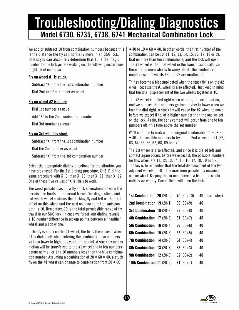
We’ll continue to work with an original combination of 20 • 60 • 40. The possible numbers to try on the 2nd wheel are 61, 62, 63, 64, 65, 66, 67, 68, 69 and 70.
The 1st wheel is also affected, and since it is dialed left and contact again occurs before we expect it, the possible numbers for this wheel are 11, 12, 13, 14, 15, 16, 17, 18, 19 and 20. The key is to remember that the total displacement of the two adjacent wheels is 10 – the maximum possible fly movement on one wheel. Keeping this in mind, here is a list of the combi-nations we will try. One of them will open the lock.
1st Combination 20 (20-0) 70 (60+10) 40 (unaffected)
2nd Combination 19 (20-1) 69 (60+9) 40
3rd Combination 18 (20-2) 68 (60+8) 40
4th Combination 17 (20-3) 67 (60+7) 40
5th Combination 16 (20-4) 66 (60+6) 40
6th Combination 15 (20-5) 65 (60+5) 40
7th Combination 14 (20-6) 64 (60+4) 40
8th Combination 13 (20-7) 63 (60+3) 40
9th Combination 12 (20-8) 62 (60+2) 40
10th Combination 11 (20-9) 61 (60+1) 40
13© Copyright 2006, Sargent & Greenleaf, Inc.
14© Copyright 2006, Sargent & Greenleaf, Inc.
Model 6730, 6735, 6738, 6741 Mechanical Combination LockTroubleshooting/Dialing Diagnostics
Dialing ten combinations is very little work compared with the alternative – drilling. It takes so little time that virtually nothing is lost in the attempt to open the lock in this nondestructive manner.
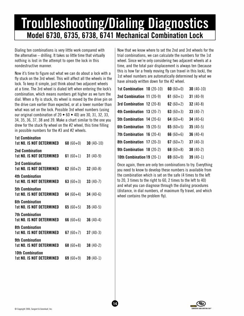
Now it’s time to figure out what we can do about a lock with a fly stuck on the 3rd wheel. This will affect all the wheels in the lock. To keep it simple, just think about two adjacent wheels at a time. The 3rd wheel is dialed left when entering the lock’s combination, which means numbers get higher as we turn the dial. When a fly is stuck, its wheel is moved by the drive pin on the drive cam earlier than expected, or at a lower number than what was set on the lock. Possible 3rd wheel numbers (using our original combination of 20 • 60 • 40) are 30, 31, 32, 33, 34, 35, 36, 37, 38 and 39. Make a chart similar to the one you drew for the stuck fly wheel on the #2 wheel, this time filling in possible numbers for the #3 and #2 wheels.
1st Combination 1st NO. IS NOT DETERMINED 60 (60+0) 30 (40-10)
2nd Combination 1st NO. IS NOT DETERMINED 61 (60+1) 31 (40-9)
3rd Combination 1st NO. IS NOT DETERMINED 62 (60+2) 32 (40-8)
4th Combination 1st NO. IS NOT DETERMINED 63 (60+3) 33 (40-7)
5th Combination 1st NO. IS NOT DETERMINED 64 (60+4) 34 (40-6)
6th Combination 1st NO. IS NOT DETERMINED 65 (60+5) 35 (40-5)
7th Combination 1st NO. IS NOT DETERMINED 66 (60+6) 36 (40-4)
8th Combination 1st NO. IS NOT DETERMINED 67 (60+7) 37 (40-3)
9th Combination 1st NO. IS NOT DETERMINED 68 (60+8) 38 (40-2)
10th Combination 1st NO. IS NOT DETERMINED 69 (60+9) 39 (40-1)
Now that we know where to set the 2nd and 3rd wheels for the trial combinations, we can calculate the numbers for the 1st wheel. Since we’re only considering two adjacent wheels at a time, and the total pair displacement is always ten (because this is how far a freely moving fly can travel in this lock), the 1st wheel numbers are automatically determined by what we have already written down for the #2 wheel.
1st Combination 10 (20-10) 60 (60+0) 30 (40-10)
2nd Combination 11 (20-9) 61 (60+1) 31 (40-9)
3rd Combination 12 (20-8) 62 (60+2) 32 (40-8)
4th Combination 13 (20-7) 63 (60+3) 33 (40-7)
5th Combination 14 (20-6) 64 (60+4) 34 (40-6)
6th Combination 15 (20-5) 65 (60+5) 35 (40-5)
7th Combination 16 (20-4) 66 (60+6) 36 (40-4)
8th Combination 17 (20-3) 67 (60+7) 37 (40-3)
9th Combination 18 (20-2) 68 (60+8) 38 (40-2)
10th Combination 19 (20-1) 69 (60+9) 39 (40-1)
Once again, there are only ten combinations to try. Everything you need to know to develop these numbers is available from the combination which is set on the safe (4 times to the left to 20, 3 times to the right to 60, 2 times to the left to 40) and what you can diagnose through the dialing procedures (distance, in dial numbers, of maximum fly travel, and which wheel contains the problem fly).
Model 6730, 6735, 6738, 6741 Mechanical Combination LockTroubleshooting/Dialing Diagnostics
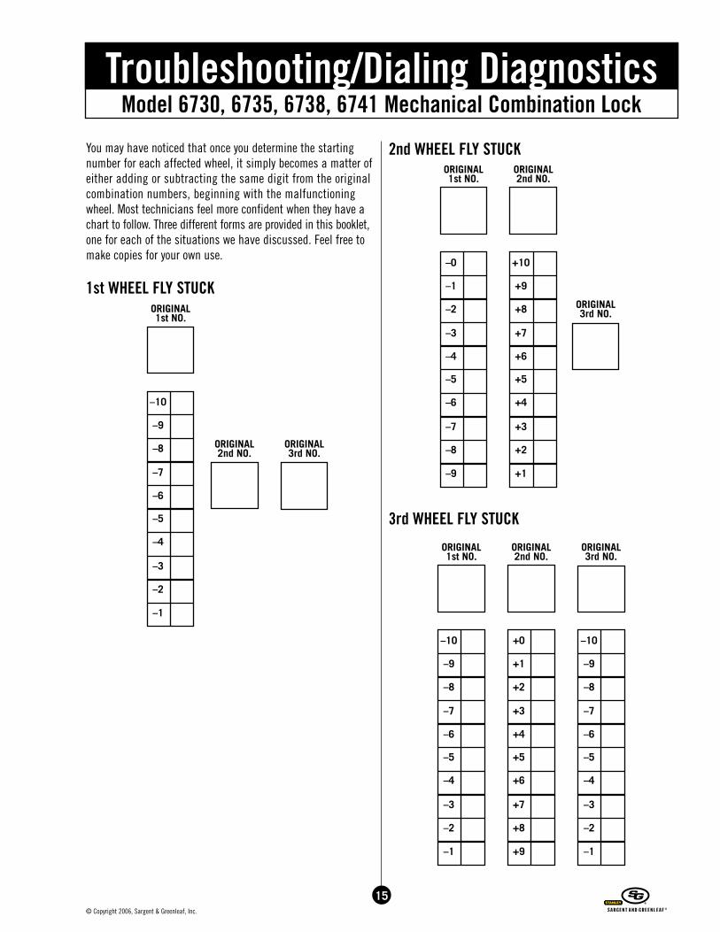
You may have noticed that once you determine the starting number for each affected wheel, it simply becomes a matter of either adding or subtracting the same digit from the original combination numbers, beginning with the malfunctioning wheel. Most technicians feel more confident when they have a chart to follow. Three different forms are provided in this booklet, one for each of the situations we have discussed. Feel free to make copies for your own use.
1st WHEEL FLY STUCK
2nd WHEEL FLY STUCK
3rd WHEEL FLY STUCK
ORIGINAL2nd NO.
ORIGINAL3rd NO.
ORIGINAL1st NO.
–10
–9
–8
–7
–6
–5
–4
–3
–2
–1
ORIGINAL2nd NO.
ORIGINAL3rd NO.
ORIGINAL1st NO.
–10
–9
–8
–7
–6
–5
–4
–3
–2
–1
ORIGINAL3rd NO.
ORIGINAL1st NO.
ORIGINAL2nd NO.
–0
–1
–2
–3
–4
–5
–6
–7
–8
–9
+10
+9
+8
+7
+6
+5
+4
+3
+2
+1
ORIGINAL1st NO.
ORIGINAL2nd NO.
ORIGINAL3rd NO.
–10
–9
–8
–7
–6
–5
–4
–3
–2
–1
–10
–9
–8
–7
–6
–5
–4
–3
–2
–1
+0
+1
+2
+3
+4
+5
+6
+7
+8
+9
15© Copyright 2006, Sargent & Greenleaf, Inc.
16© Copyright 2006, Sargent & Greenleaf, Inc.
Model 6730, 6735, 6738, 6741 Mechanical Combination LockTroubleshooting/Dialing Diagnostics
Loose sPLine key
Proper installation of the correct spline key will prevent this problem from occurring. The proper spline key is one which fits snugly into the keyway milled into both the drive cam and spindle. You should not be able to insert and remove it with your fingers. It should be seated with a small, light hammer and require side cutters or a spline key removal tool to extract. A properly seated S&G spline key is oriented with the flag over and just touching the drive cam. Before 1988, spline keys were meant to be oriented with the flag crossing over and just touching the spindle. A spline key is a press-fit part, mean-ing it is slightly deformed when it is seated. Upon removal, it should always be discarded and replaced with a new, unused one. The current spline key number for S&G Group 2 locks is U17. Stocking and using new spline keys will prevent the prob-lems we will cover.
The spline key ties the dial/spindle assembly directly to the drive cam, making these components act as one part. When the dial is turned any number of degrees, the drive cam rotates exactly the same number of degrees…as long as the drive cam stays firmly attached to the drive spindle. If the connection is sloppy, due to a worn or undersize spline key, a ten number turn of the dial will likely result in an eight or nine number turn of the drive cam. In other words, drive cam rota-tion lags behind the dial by a number or two, just enough to keep the lock from opening.
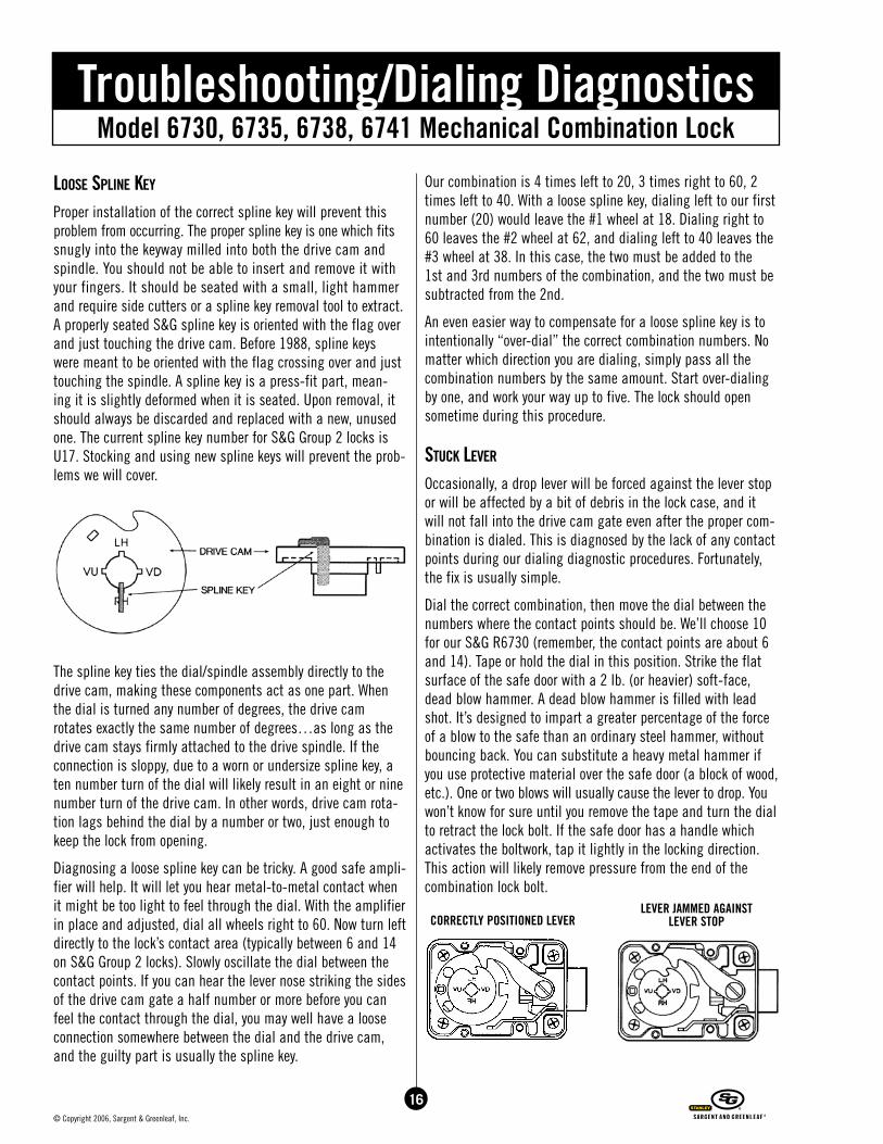
Diagnosing a loose spline key can be tricky. A good safe ampli-fier will help. It will let you hear metal-to-metal contact when it might be too light to feel through the dial. With the amplifier in place and adjusted, dial all wheels right to 60. Now turn left directly to the lock’s contact area (typically between 6 and 14 on S&G Group 2 locks). Slowly oscillate the dial between the contact points. If you can hear the lever nose striking the sides of the drive cam gate a half number or more before you can feel the contact through the dial, you may well have a loose connection somewhere between the dial and the drive cam, and the guilty part is usually the spline key.
Our combination is 4 times left to 20, 3 times right to 60, 2 times left to 40. With a loose spline key, dialing left to our first number (20) would leave the #1 wheel at 18. Dialing right to 60 leaves the #2 wheel at 62, and dialing left to 40 leaves the #3 wheel at 38. In this case, the two must be added to the 1st and 3rd numbers of the combination, and the two must be subtracted from the 2nd.
An even easier way to compensate for a loose spline key is to intentionally “over-dial” the correct combination numbers. No matter which direction you are dialing, simply pass all the combination numbers by the same amount. Start over-dialing by one, and work your way up to five. The lock should open sometime during this procedure.
stuck Lever
Occasionally, a drop lever will be forced against the lever stop or will be affected by a bit of debris in the lock case, and it will not fall into the drive cam gate even after the proper com-bination is dialed. This is diagnosed by the lack of any contact points during our dialing diagnostic procedures. Fortunately, the fix is usually simple.
Dial the correct combination, then move the dial between the numbers where the contact points should be. We’ll choose 10 for our S&G R6730 (remember, the contact points are about 6 and 14). Tape or hold the dial in this position. Strike the flat surface of the safe door with a 2 lb. (or heavier) soft-face, dead blow hammer. A dead blow hammer is filled with lead shot. It’s designed to impart a greater percentage of the force of a blow to the safe than an ordinary steel hammer, without bouncing back. You can substitute a heavy metal hammer if you use protective material over the safe door (a block of wood, etc.). One or two blows will usually cause the lever to drop. You won’t know for sure until you remove the tape and turn the dial to retract the lock bolt. If the safe door has a handle which activates the boltwork, tap it lightly in the locking direction. This action will likely remove pressure from the end of the combination lock bolt.
CORRECTLY POSITIONED LEVERLEVER JAMMED AGAINST
LEVER STOP
Model 6730, 6735, 6738, 6741 Mechanical Combination LockTroubleshooting/Dialing Diagnostics
Broken Lever sPring
Although quite rare, a broken lever spring can produce the same results as a stuck lever. If the lock is mounted right-hand, gravity will tend to pull the lever into the wheel and drive cam gates when they are all lined up properly. A left-hand mounting configuration orients the lever so gravity works against a successful safe opening. A non-forced opening requires you to actually turn the safe upside down. When the weight of the safe and its environment permit this, it’s a good solution. A broken lever spring in a vertical-up or vertical-down mounted lock can sometimes be overcome by dialing so all wheel gates are under the fence and the drive cam gate is under the lever nose, then vibrating the safe door with a dead blow hammer. The dial will have to be moved a few numbers in the direction which would normally retract the lock bolt after each blow, to see if the lever has moved in the desired direction. Failing this, the safe will have to be tipped on one of its sides to accom-plish a non-forced opening.
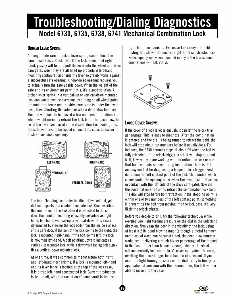
The term “handing” can refer to either of two related, yet distinct aspects of a combination safe lock. One describes the orientation of the lock after it is attached to the safe door. The hand of mounting is usually described as right-hand, left-hand, vertical-up or vertical-down. It is easily determined by viewing the lock body from the inside surface of the safe door. If the bolt of the lock points to the right, the lock is mounted right-hand. If the bolt points left, the lock is mounted left-hand. A bolt pointing upward indicates a vertical-up mounted lock, while a downward facing bolt signi-fies a vertical-down mounted lock.
At one time, it was common to manufacture both right and left-hand mechanisms. If a lock is mounted left-hand and its lever fence is located at the top of the lock case, it is a true left-hand constructed lock. Current production locks are all, with the exception of some vault locks, true
right-hand mechanisms. Extensive laboratory and field testing has shown the modern right-hand constructed lock works equally well when mounted in any of the four common orientations (RH, LH, VU, VD).
Loose cover screws
If the cover of a lock is loose enough, it can let the relock trig-ger engage. This is easy to diagnose. After the combination is entered and the dial is being turned to retract the bold, the lock will stop about ten numbers before it usually does. For instance, the 6730 normally stops at about 95 when the bolt is fully retracted. If the relock trigger is set, it will stop at about 5. If, however, you are working with an unfamiliar lock or one that has been mis-splined during installation, there is still an easy method for diagnosing a tripped relock trigger. First, determine the left contact point of the lock (the number which comes under the opening index when the lever nose first comes in contact with the left side of the drive cam gate). Now dial the combination and turn to retract the combination lock bolt. The dial will stop before bolt retraction. If the stopping point is within one or two numbers of the left contact point, something is preventing the bolt from moving into the lock case. It’s very likely the relock trigger.
Before you decide to drill, try the following technique: While exerting very light turning pressure on the dial in the unlocking direction, firmly rap the door in the vicinity of the lock, using at least a 2 lb. dead blow hammer (although a metal hammer and block of wood can be substituted, the dead blow hammer works best, delivering a much higher percentage of the impact to the door, rather than bouncing back). Ideally, the shock will momentarily bounce the lock’s cover up against the case, resetting the relock trigger for a fraction of a second. If you maintain light turning pressure on the dial, or try to time your application of pressure with the hammer blow, the bolt will be able to move into the case.
LEFT-HAND
VERTICAL-UP
VERTICAL-DOWN
RIGHT-HAND
17© Copyright 2006, Sargent & Greenleaf, Inc.
18© Copyright 2006, Sargent & Greenleaf, Inc.
Model 6730, 6735, 6738, 6741 Mechanical Combination LockTroubleshooting/Dialing Diagnostics
coMBination changing Mistakes
The combination changing process presents a lot of opportuni-ties for a lockout. Even for an experienced technician, a mental lapse can cause minor or major headaches. Sargent & Greenleaf key changeable locks come in two varieties: zero change and regular change. A zero change lock uses a single index on the dial ring to open the lock and to change the combination. It’s impossible to choose the wrong index when setting new numbers.
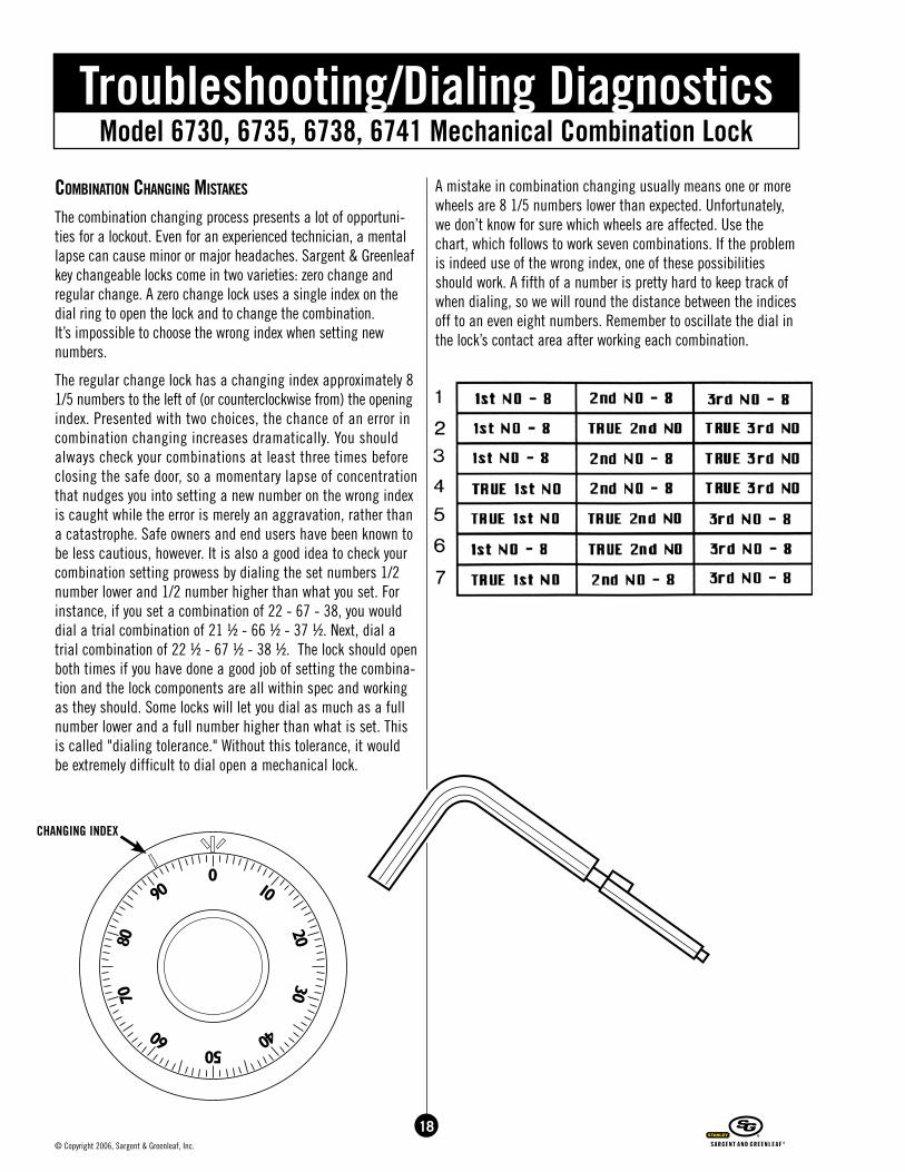
The regular change lock has a changing index approximately 8 1/5 numbers to the left of (or counterclockwise from) the opening index. Presented with two choices, the chance of an error in combination changing increases dramatically. You should always check your combinations at least three times before closing the safe door, so a momentary lapse of concentration that nudges you into setting a new number on the wrong index is caught while the error is merely an aggravation, rather than a catastrophe. Safe owners and end users have been known to be less cautious, however. It is also a good idea to check your combination setting prowess by dialing the set numbers 1/2 number lower and 1/2 number higher than what you set. For instance, if you set a combination of 22 - 67 - 38, you would dial a trial combination of 21 ½ - 66 ½ - 37 ½. Next, dial a trial combination of 22 ½ - 67 ½ - 38 ½. The lock should open both times if you have done a good job of setting the combina-tion and the lock components are all within spec and working as they should. Some locks will let you dial as much as a full number lower and a full number higher than what is set. This is called "dialing tolerance." Without this tolerance, it would be extremely difficult to dial open a mechanical lock.
A mistake in combination changing usually means one or more wheels are 8 1/5 numbers lower than expected. Unfortunately, we don’t know for sure which wheels are affected. Use the chart, which follows to work seven combinations. If the problem is indeed use of the wrong index, one of these possibilities should work. A fifth of a number is pretty hard to keep track of when dialing, so we will round the distance between the indices off to an even eight numbers. Remember to oscillate the dial in the lock’s contact area after working each combination.
CHANGING INDEX
Model 6730, 6735, 6738, 6741 Mechanical Combination LockTroubleshooting/Dialing Diagnostics
wheeL sLiPPage
This is a very rare condition on current production S&G locks, and is more often associated with other brands. S&G employs a double-locking wheel in its premium locks, using a total of 28 gear teeth to lock the wheel center to the wheel case.
When slippage occurs, it most often involves the last wheel (#3 in a three-wheel lock). The last wheel is between the drive cam and the other wheels. It takes the brunt of any abuse delivered via the drive cam. If the dial is moved in a snapping motion, the drive cam literally slams the last wheel into motion. The impact drives the wheel center into motion while the laws of physics tell us the mass of the wheel case wants to stay at rest. Sometimes it will do so, if only for a fraction of a second; long enough to change its relationship with the wheel center by a few numbers.
Another situation which can cause wheel slippage is setting the last number of the combination on or between the lock’s two contact points – in the “Forbidden Zone.” This causes a condition known as a “lock-in.” The combination can be entered to retract the bolt. However, when it’s time to extend the bolt the drive cam attempts to move the last wheel before the fence is lifted out of the wheel’s gate. It’s like isometric exercise; two forces are working against each other, and no movement is taking place. Stress is created between the last wheel’s center and its case, and one way for this stress to be relieved is for the wheel to slip a few numbers, until the fence can be raised far enough to release the wheel.
The end result is a new number on the last wheel. Some simple and efficient dialing will allow us to open the lock, however. Let’s use our sample combination of 20 • 60 • 40. After dialing four times left to 20, dial three times right to 60, then two times left to 62. Remember, the “left two times to 62” is only two numbers more than a single revolution. Every time you pass a number, no matter how close it is to your starting point, it’s counted as one turn to that number.
Now dial right to the contact area and oscillate the dial between the contact points a few times. If the wheels are almost aligned well enough to allow the fence to drop into the gates, the vibration may move the wheels enough to allow the lock to open.
If the lever doesn’t drop, dial left directly to 64, then back to the contact area and oscillate. The only wheel you have moved is the last one, and only by two numbers. You should
repeat this procedure, adding 2 to the last wheel number, until the lock opens or until you have worked your way all the way around the dial. The procedure only takes a few min-utes. Dialing to overcome a slipped wheel in another position requires more time (and dialing), but is accomplished the same way. Keep two of the wheels set on their original num-bers while trying every other number on the remaining wheel.
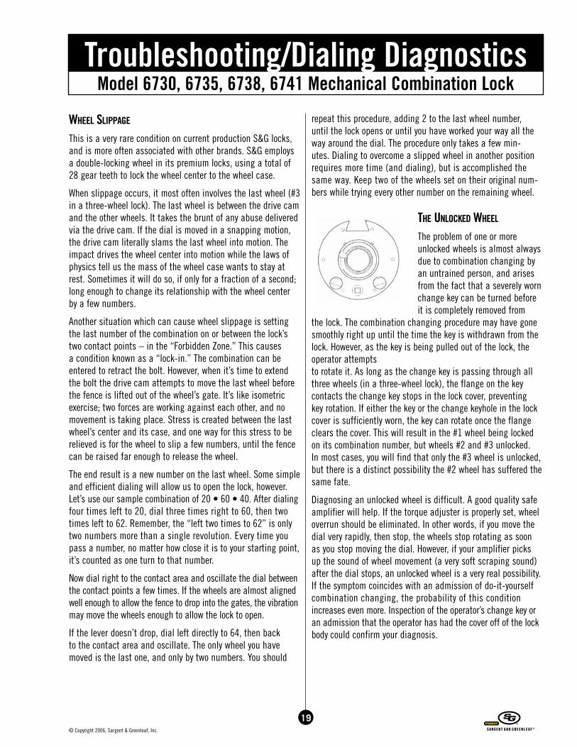
the unLockeD wheeL
The problem of one or more unlocked wheels is almost always due to combination changing by an untrained person, and arises from the fact that a severely worn change key can be turned before it is completely removed from
the lock. The combination changing procedure may have gone smoothly right up until the time the key is withdrawn from the lock. However, as the key is being pulled out of the lock, the operator attempts to rotate it. As long as the change key is passing through all three wheels (in a three-wheel lock), the flange on the key contacts the change key stops in the lock cover, preventing key rotation. If either the key or the change keyhole in the lock cover is sufficiently worn, the key can rotate once the flange clears the cover. This will result in the #1 wheel being locked on its combination number, but wheels #2 and #3 unlocked. In most cases, you will find that only the #3 wheel is unlocked, but there is a distinct possibility the #2 wheel has suffered the same fate.
Diagnosing an unlocked wheel is difficult. A good quality safe amplifier will help. If the torque adjuster is properly set, wheel overrun should be eliminated. In other words, if you move the dial very rapidly, then stop, the wheels stop rotating as soon as you stop moving the dial. However, if your amplifier picks up the sound of wheel movement (a very soft scraping sound) after the dial stops, an unlocked wheel is a very real possibility. If the symptom coincides with an admission of do-it-yourself combination changing, the probability of this condition increases even more. Inspection of the operator’s change key or an admission that the operator has had the cover off of the lock body could confirm your diagnosis.
19© Copyright 2006, Sargent & Greenleaf, Inc.
20© Copyright 2006, Sargent & Greenleaf, Inc.
Model 6730, 6735, 6738, 6741 Mechanical Combination LockTroubleshooting/Dialing Diagnostics
Even though a wheel is unlocked, it will seldom slip if you dial smoothly and slowly. The critical time occurs when a drive pin first contacts the fly on the unlocked wheel. Slow, smooth dialing gives the friction, which exists between the wheel center and the case time to overcome the inertia (tendency to stay in place) of the wheel case.
Our original combination was set to 20 • 60 • 40. For our example, we’ll assume only the #3 wheel is unlocked. This means our first two numbers are 20 and 60, and the third num-ber could be anything. Moving slowly and smoothly, we dial four times left to 20, then three times right to 60. Although slow dialing is not critical at this time, we don’t want to encourage any unnecessary slippage in the #3 wheel, because the more times it slips, the greater its tendency to slip during upcoming dialing operations.
The dial is now set on our second number, 60. Dial left two times to 62, then right to the contact area. It’s okay to oscillate the dial in the contact area, because only the drive cam is moving, and it is not contacting the #3 wheel. If the lock does not open, dial left directly to 64, then right to the contact area. Keep adding 2 to your previous 3rd wheel number until the lock opens.
If the opening doesn’t take place, chances are very good the #2 wheel is also unlocked. To remedy this, dial four times left to 20, then three times right to 18. Now dial two times left to 20, then directly right to the contact area and oscillate. Dial directly left to 22, then back to the contact area, and so on. After you’ve worked the #3 wheel all the way around the dial, you can drop another two numbers down on the #2 wheel by dialing four times left to 20, then three times right to 16. Begin checking the #3 wheel with number 18, and again work the #3 wheel all the way around the dial.
Yes, this can be a time consuming process, but remember that the most likely situation is for only the #3 wheel to be unlocked. In any event, dialing open a safe is almost always preferable to drilling it open.
concLusion
These diagnostics and opening techniques have been compiled for Group 2 locks, although most will work on Group 1 locks as well. I encourage anyone who has additional techniques or improvement on the ones given here to jot them down and send them to me. I’ll make sure they are tested and added to the list. Remember, we’re looking for non-destructive diagnostic and opening procedures. Send your comments and suggestions to:
Brian Costley, CML, CMST Sargent & Greenleaf One Security Drive Nicholasville, KY 40356
Model 6730, 6735, 6738, 6741 Mechanical Combination LockTroubleshooting/Dialing Diagnostics
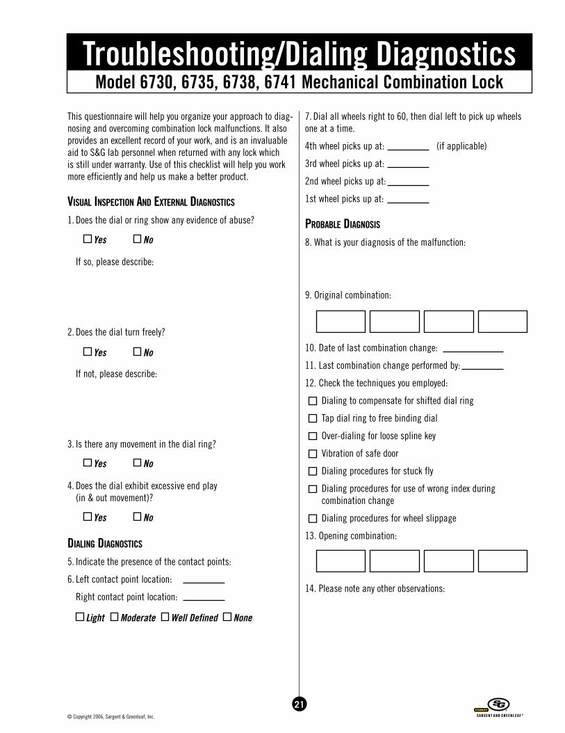
This questionnaire will help you organize your approach to diag-nosing and overcoming combination lock malfunctions. It also provides an excellent record of your work, and is an invaluable aid to S&G lab personnel when returned with any lock which is still under warranty. Use of this checklist will help you work more efficiently and help us make a better product.
visuaL insPection anD externaL Diagnostics
1. Does the dial or ring show any evidence of abuse?
If so, please describe:
2. Does the dial turn freely?
If not, please describe:
3. Is there any movement in the dial ring?
4. Does the dial exhibit excessive end play (in & out movement)?
DiaLing Diagnostics
5. Indicate the presence of the contact points:
6. Left contact point location:
Right contact point location:
7. Dial all wheels right to 60, then dial left to pick up wheels one at a time.
4th wheel picks up at: (if applicable)
3rd wheel picks up at:
2nd wheel picks up at:
1st wheel picks up at:
ProBaBLe Diagnosis
8. What is your diagnosis of the malfunction:
9. Original combination:
10. Date of last combination change:
11. Last combination change performed by:
12. Check the techniques you employed:
Dialing to compensate for shifted dial ring
Tap dial ring to free binding dial
Over-dialing for loose spline key
Vibration of safe door
Dialing procedures for stuck fly
Dialing procedures for use of wrong index during combination change
Dialing procedures for wheel slippage
13. Opening combination:
14. Please note any other observations:
Yes No
Yes No
Yes No
Yes No
Light Moderate Well Defined None
21© Copyright 2006, Sargent & Greenleaf, Inc.
22© Copyright 2006, Sargent & Greenleaf, Inc.
Model 6730, 6735, 6738, 6741 Mechanical Combination LockTroubleshooting/Dialing Diagnostics
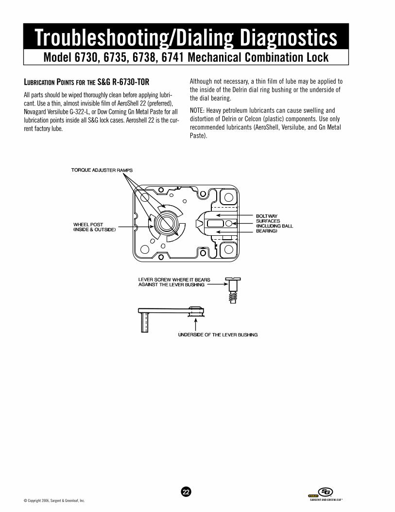
LuBrication Points for the s&g r-6730-torAll parts should be wiped thoroughly clean before applying lubri-cant. Use a thin, almost invisible film of AeroShell 22 (preferred), Novagard Versilube G-322-L, or Dow Corning Gn Metal Paste for all lubrication points inside all S&G lock cases. Aeroshell 22 is the cur-rent factory lube.
Although not necessary, a thin film of lube may be applied to the inside of the Delrin dial ring bushing or the underside of the dial bearing.
NOTE: Heavy petroleum lubricants can cause swelling and distortion of Delrin or Celcon (plastic) components. Use only recommended lubricants (AeroShell, Versilube, and Gn Metal Paste).
Model 6730, 6735, 6738, 6741 Mechanical Combination LockTroubleshooting/Dialing Diagnostics
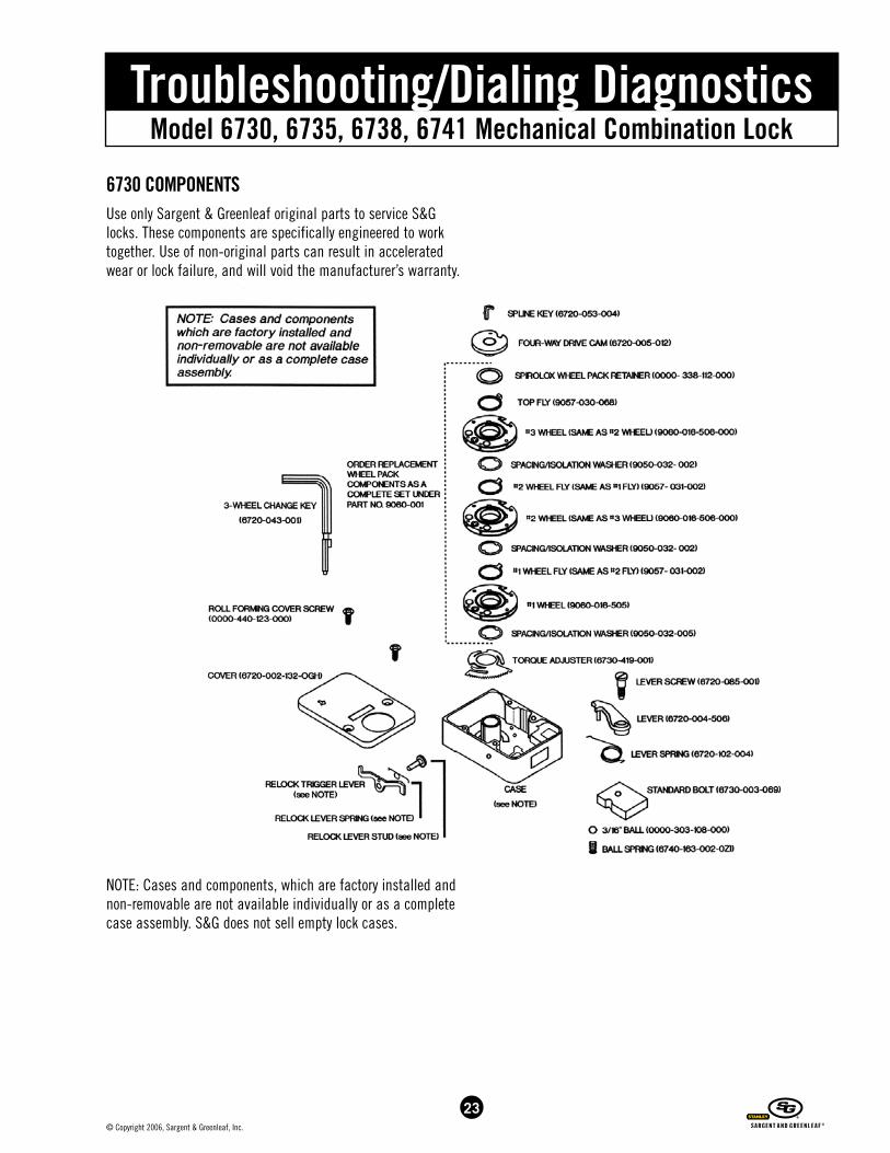
6730 coMPonentsUse only Sargent & Greenleaf original parts to service S&G locks. These components are specifically engineered to work together. Use of non-original parts can result in accelerated wear or lock failure, and will void the manufacturer’s warranty.
NOTE: Cases and components, which are factory installed and non-removable are not available individually or as a complete case assembly. S&G does not sell empty lock cases.
23© Copyright 2006, Sargent & Greenleaf, Inc.

NOTES


Corporate Headquarters
One Security Drive
Nicholasville, KY 40356
European Headquarters
9, chemin du Croset
1024 Ecublens
Switzerland
www.sargentandgreenleaf.com
Document 630-672
Revised 12/15/2009/BC