installation instructions for 7 line lever lock - … · installation instructions for 7 line lever...
TRANSCRIPT
1
2
3 4
5 67
89
10
14
15
17
18
16
22
20
20
19
11 12
13
21
2
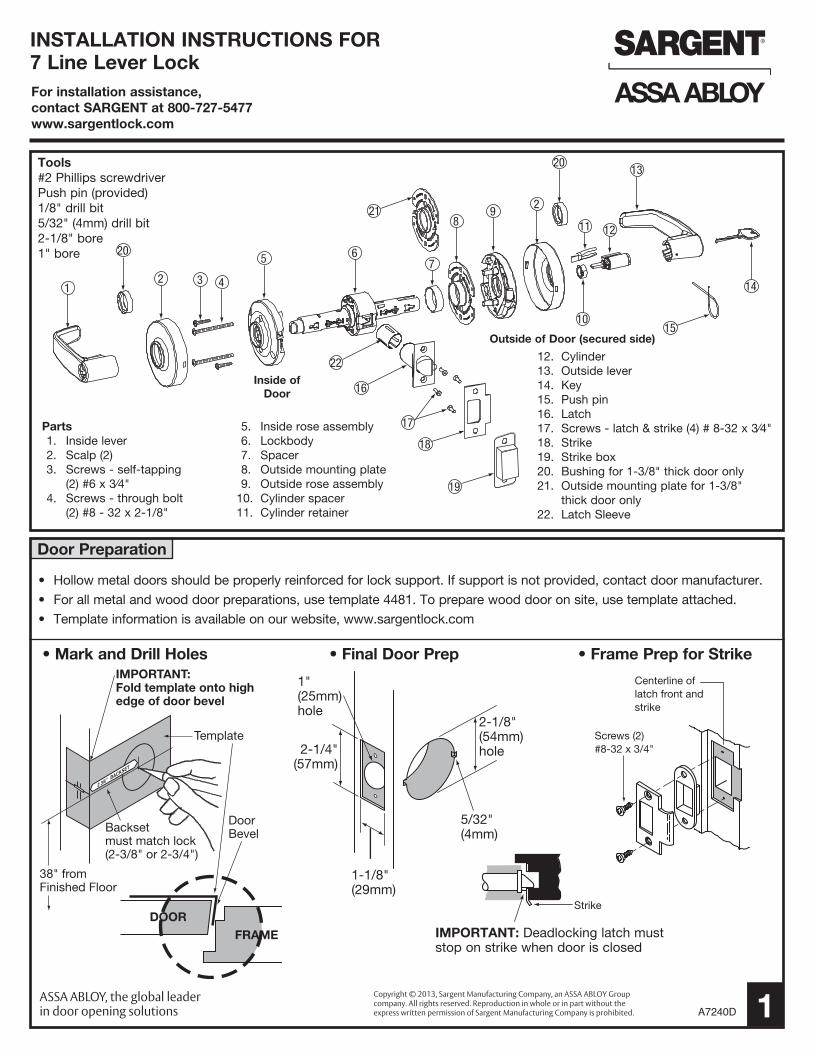
INSTALLATION INSTRUCTIONS FOR7 Line Lever Lock For installation assistance,contact SARGENT at 800-727-5477www.sargentlock.com
Door Preparation
IMPORTANT:Fold template onto highedge of door bevel
38" fromFinished Floor
Template
DoorBevel
DOORFRAME
Backsetmust match lock (2-3/8" or 2-3/4")
• Hollow metal doors should be properly reinforced for lock support. If support is not provided, contact door manufacturer.
• For all metal and wood door preparations, use template 4481. To prepare wood door on site, use template attached.
• Template information is available on our website, www.sargentlock.com
2-1/8"(54mm)hole
5/32"(4mm)
1-1/8" (29mm)
2-1/4"(57mm)
1"(25mm) hole
Strike
IMPORTANT: Deadlocking latch must stop on strike when door is closed
• Final Door Prep • Frame Prep for Strike
Parts 1. Inside lever 2. Scalp (2) 3. Screws - self-tapping (2) #6 x 3⁄4" 4. Screws - through bolt (2) #8 - 32 x 2-1/8"
5. Inside rose assembly 6. Lockbody 7. Spacer 8. Outside mounting plate 9. Outside rose assembly 10. Cylinder spacer 11. Cylinder retainer
Tools#2 Phillips screwdriverPush pin (provided)1/8" drill bit5/32" (4mm) drill bit2-1/8" bore1" bore
1
Screws (2)#8-32 x 3/4"
Centerline oflatch front andstrike
Outside of Door (secured side)
Inside of Door
• Mark and Drill Holes
12. Cylinder 13. Outside lever 14. Key 15. Push pin 16. Latch 17. Screws - latch & strike (4) # 8-32 x 3⁄4" 18. Strike 19. Strike box 20. Bushing for 1-3/8" thick door only 21. Outside mounting plate for 1-3/8" thick door only 22. Latch Sleeve
Copyright © 2013, Sargent Manufacturing Company, an ASSA ABLOY Group company. All rights reserved. Reproduction in whole or in part without the express written permission of Sargent Manufacturing Company is prohibited. A7240D

Preset Lock Latch Installation
Doorframe
2A
3
1 2Install latch and sleeve (1" prep) loosely; tighten
screws after step #3
Screws (2) #8-32 x 3/4"
Outside of Door
Door thickness – 1-3/4" (44mm) - centered
• See step 2A for adjusting for 1-3/8" (35mm) thick doors
2
• Disassemble — outside lever (see page 3), scalp, outside rose assembly, outside mounting plate and spacer
• Reassemble — Add 3 parts (2 bushings and slim mounting plate) as shown below in boxed areas
• IMPORTANT: To center lock in door, rotate threaded mounting plate on completely
Adjustment for 1-3/8" (35mm) Thick Door
Through-bolt screws(2) #8-32 x 2-1/8"
Self-tapping screws(2) # 6 x 3/4"
Scalp- twist to secure on to rose
IMPORTANTLockbody must be centered
in the door
Test for proper operation
before closing
door
• IMPORTANT: Self-tapping screws MUST be installed
A7240DCopyright © 2013, Sargent Manufacturing Company, an ASSA ABLOY Group company. All rights reserved. Reproduction in whole or in part without the express written permission of Sargent Manufacturing Company is prohibited.
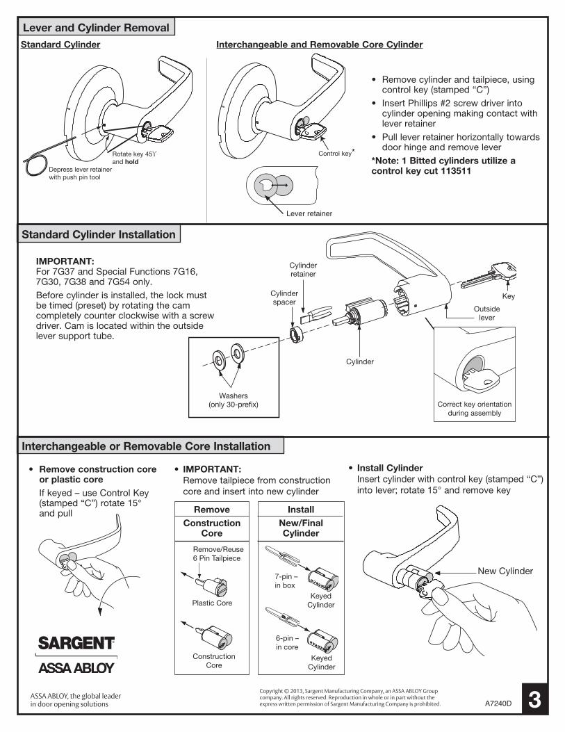
Lever and Cylinder Removal
Standard Cylinder Installation
Interchangeable or Removable Core Installation
Rotate key 45ϒand hold
Depress lever retainer with push pin tool
Control key*
C
Rotate key 45ϒand hold
Depress lever retainer with push pin tool
Control key*
C
Remove/Reuse6 Pin Tailpiece
Plastic Core
ConstructionCore
7-pin – in box
6-pin – in core
KeyedCylinder
KeyedCylinder
C
New Cylinder
Washers(only 30-prefix)
Cylinderretainer
Cylinder
Outsidelever
KeyCylinderspacer
IMPORTANT: For 7G37 and Special Functions 7G16, 7G30, 7G38 and 7G54 only.
Before cylinder is installed, the lock must be timed (preset) by rotating the cam completely counter clockwise with a screw driver. Cam is located within the outside lever support tube.
• Remove cylinder and tailpiece, using control key (stamped “C”)
• Insert Phillips #2 screw driver into cylinder opening making contact with lever retainer
• Pull lever retainer horizontally towards door hinge and remove lever
*Note: 1 Bitted cylinders utilize a control key cut 113511
4
Correct key orientation during assembly
• IMPORTANT: Remove tailpiece from construction core and insert into new cylinder
• Install Cylinder Insert cylinder with control key (stamped “C”)
into lever; rotate 15° and remove key
• Remove construction core or plastic core If keyed – use Control Key
(stamped “C”) rotate 15° and pull
Remove/Reuse6 Pin Tailpiece
Plastic Core
ConstructionCore
7-pin – in box
6-pin – in core
KeyedCylinder
KeyedCylinder
C
New Cylinder
Remove/Reuse6 Pin Tailpiece
Plastic Core
ConstructionCore
7-pin – in box
6-pin – in core
KeyedCylinder
KeyedCylinder
C
New Cylinder
Remove/Reuse6 Pin Tailpiece
Plastic Core
ConstructionCore
7-pin – in box
6-pin – in core
KeyedCylinder
KeyedCylinder
C
New Cylinder
Remove/Reuse6 Pin Tailpiece
Plastic Core
ConstructionCore
7-pin – in box
6-pin – in core
KeyedCylinder
KeyedCylinder
C
New Cylinder
C
RemoveConstruction
Core
InstallNew/Final Cylinder
3
Lever retainer
Standard Cylinder Interchangeable and Removable Core Cylinder
Copyright © 2013, Sargent Manufacturing Company, an ASSA ABLOY Group company. All rights reserved. Reproduction in whole or in part without the express written permission of Sargent Manufacturing Company is prohibited. A7240D
Install 7U94/7U94-2
4
Install 7U93
Through-bolt Screws (2)
# 8 - 32 x 2-1/8"Cup
Washers (2)Self-tapping
screws (2) # 6 x 3/4"
Scalp- twist to secure on to rose
Scalp- twist to secure on to rose
Det
erm
ine
corr
ect
bac
kset
and
doo
r th
ickn
ess
- th
en p
lace
tem
pla
teon
doo
r an
d m
ark
for
hole
s.
Hig
h ed
ge
of b
evel
edd
oor
Bor
e 2-
1/8"
hole
thr
ud
oor
Cut
out
to
fitlo
ck fr
ont,
as
show
n
Bor
e 1"
hol
eth
ru in
to fi
rst
hole
(thi
sho
le m
ust
be
cent
ered
in
doo
r ed
ge a
ndm
ust
be
par
alle
lto
sid
es).
38" from floorrecommended height
Sw
ivel
fron
tla
tch
std
. for
flat
and
bev
eled
doo
rs
Cen
terli
ne fo
r st
rike
scre
ws
and
fron
t sc
rew
s
To p
rep
door
for l
ock
To m
ortis
e fr
ame
for s
trik
e
Cut
out
jam
b fo
rst
rike
Sto
p
Lock
Str
ike
Gua
rdb
olt
stop
s on
str
ike
whe
n d
oor
is c
lose
d.
See
reve
rse
side
Whe
n st
rike
box
is n
otus
ed, r
eces
s in
jam
bm
ust
be
dee
p e
noug
hto
allo
w la
tchb
olt
toex
tend
its
full
free
leng
th.
Loca
te s
trik
e sc
rew
s at
1/
2 th
e d
oor
thic
knes
sm
easu
red
from
sto
p.
5/32
(4m
m)
1-1/
8(2
9mm
)2-
1/4
(57m
m)1
23
4
No
te -
Con
sult
fact
ory
for
corr
ect
tem
pla
te
info
rmat
ion
for
38-2
, 93,
94, a
nd 9
4-2
func
tions
2-1/
4" (5
7mm
)2"
(51m
m)
1-3/
4" (4
4mm
)
1-3/
8" (3
5mm
)
Fold
her
e on
high
ed
ge o
f b
evel
ed d
oor
Dril
l 1"
(25m
m)
hole
at
cent
er o
f d
oor
thic
knes
s
5/32
" D
ia. (
15m
m)
A63
05F
IMPO
RTA
NT
SEE
BA
CK
FO
R D
IREC
TIO
NS
BACKSET
Sta
ndar
d6
line
Sta
ndar
d7,
8 &
9lin
e
2-3/
8" B
acks
et
(60m
m) N
omin
al
2-3/
4" B
acks
et
(70m
m) N
omin
al
3-3/
4" B
acks
et
(95m
m) N
omin
al
2-1/
8" D
ia.
5" B
acks
et
(127
mm
) Nom
inal
®
A7240DCopyright © 2013, Sargent Manufacturing Company, an ASSA ABLOY Group company. All rights reserved. Reproduction in whole or in part without the express written permission of Sargent Manufacturing Company is prohibited.
6305 Template