s&g audit lock - sargent and greenleaf
TRANSCRIPT
Programming and Operations Guide
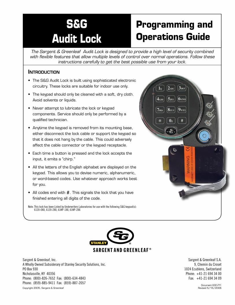
The Sargent & Greenleaf Audit Lock is designed to provide a high level of security combined with flexible features that allow multiple levels of control over normal operations. Follow these
instructions carefully to get the best possible use from your lock.
Document 630-711Revised 5/16/2006Copyright 2005, Sargent & Greenleaf
IntroductIon
• The S&G Audit Lock is built using sophisticated electronic circuitry. These locks are suitable for indoor use only.
• The keypad should only be cleaned with a soft, dry cloth. Avoid solvents or liquids.
• Never attempt to lubricate the lock or keypad components. Service should only be performed by a qualified technician.
• Anytime the keypad is removed from its mounting base, either disconnect the lock cable or support the keypad so that it does not hang by the cable. This could adversely affect the cable connector or the keypad receptacle.
• Each time a button is pressed and the lock accepts the input, it emits a “chirp.”
• All the letters of the English alphabet are displayed on the keypad. This allows you to devise numeric, alphanumeric, or word-based codes. Use whatever approach works best for you.
• All codes end with #. This signals the lock that you have finished entering all digits of the code.
Note: This lock has been Listed by Underwriters Laboratories for use with the following S&G keypad(s): 6120-0XX, 6120-2XX, 61KP-1XX, 61KP-2XX
S&GAudit Lock
Sargent & Greenleaf, Inc.A Wholly Owned Subsiderary of Stanley Security Solutions, Inc.PO Box 930Nicholasville, KY 40356Phone: (800)-826-7652 Fax: (800)-634-4843Phone: (859)-885-9411 Fax: (859)-887-2057
Sargent & Greenleaf S.A.9, Chemin du Croset
1024 Ecublens, SwitzerlandPhone: +41-21 694 34 00
Fax: +41-21 694 34 09

1
S&G AUDIT LOCK PROGRAMMING & OPERATIONS GUIDE
S&G Audit Lock ELECTRONIC LOCK
Programming and Operations Guide
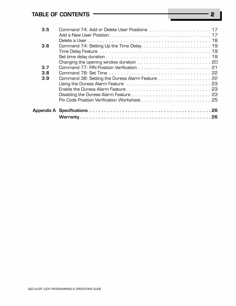
TABLE OF CONTENTS
1. GENERAL INFORMATION . . . . . . . . . . . . . . . . . . . . . . . . . . . . 3 1.1 About Your Locking System . . . . . . . . . . . . . . . . . . . . . . . . . . . . . . . . . . . . . 3 1.2 Factory Default Settings . . . . . . . . . . . . . . . . . . . . . . . . . . . . . . . . . . . . . . . 4
2. OPERATING THE LOCK . . . . . . . . . . . . . . . . . . . . . . . . . . . . . . 5 2.1 Operating Mode, PIN Positions, and User Codes . . . . . . . . . . . . . . . . . . . . . . . 5 2.1.1 Operating Mode. . . . . . . . . . . . . . . . . . . . . . . . . . . . . . . . . . . . . . . . . . . . . 5 2.1.2 Setting the Operating Mode. . . . . . . . . . . . . . . . . . . . . . . . . . . . . . . . . . . . . 6 2.2 PIN Positions and Access Responsibilities . . . . . . . . . . . . . . . . . . . . . . . . . . . 8 2.3 Beep Patterns. . . . . . . . . . . . . . . . . . . . . . . . . . . . . . . . . . . . . . . . . . . . . 10 2.3.1 Beep Pattern Table . . . . . . . . . . . . . . . . . . . . . . . . . . . . . . . . . . . . . . . . . 10 2.4 Opening the Lock . . . . . . . . . . . . . . . . . . . . . . . . . . . . . . . . . . . . . . . . . . . 11 2.5 Keypad Input Errors and Clearing the Lock . . . . . . . . . . . . . . . . . . . . . . . . . . 11 2.6 Penalty Time . . . . . . . . . . . . . . . . . . . . . . . . . . . . . . . . . . . . . . . . . . . . . . 12 2.7 Bolt Extension Indicator. . . . . . . . . . . . . . . . . . . . . . . . . . . . . . . . . . . . . . . 12 2.8 Keypad Tamper Indicator (an optional feature) . . . . . . . . . . . . . . . . . . . . . . . 12 2.9 Low Battery Indicator . . . . . . . . . . . . . . . . . . . . . . . . . . . . . . . . . . . . . . . . 13 2.10 Changing Batteries. . . . . . . . . . . . . . . . . . . . . . . . . . . . . . . . . . . . . . . . . . 13 2.11 iButton Touch Key . . . . . . . . . . . . . . . . . . . . . . . . . . . . . . . . . . . . . . . . . . 13
3. PROGRAMMING THE LOCK. . . . . . . . . . . . . . . . . . . . . . . . . . 14 3.1 Command 22: Changing a PIN Code . . . . . . . . . . . . . . . . . . . . . . . . . . . . . . 14 3.2 Command 28: Audit Download. . . . . . . . . . . . . . . . . . . . . . . . . . . . . . . . . . 15 3.3 Command 43: Identifying the Type of Lock . . . . . . . . . . . . . . . . . . . . . . . . . . 16 3.4 Command 73: Set Date . . . . . . . . . . . . . . . . . . . . . . . . . . . . . . . . . . . . . . 16
2
S&G AUDIT LOCK PROGRAMMING & OPERATIONS GUIDE
TABLE OF CONTENTS
3.5 Command 74: Add or Delete User Positions . . . . . . . . . . . . . . . . . . . . . 17 Add a New User Position. . . . . . . . . . . . . . . . . . . . . . . . . . . . . . . . . . . 17 Delete a User . . . . . . . . . . . . . . . . . . . . . . . . . . . . . . . . . . . . . . . . . . 18 3.6 Command 74: Setting Up the Time Delay. . . . . . . . . . . . . . . . . . . . . . . . 19 Time Delay Feature . . . . . . . . . . . . . . . . . . . . . . . . . . . . . . . . . . . . . . 19 Set time delay duration . . . . . . . . . . . . . . . . . . . . . . . . . . . . . . . . . . . . 19 Changing the opening window duration . . . . . . . . . . . . . . . . . . . . . . . . . 20 3.7 Command 77: PIN Position Verification . . . . . . . . . . . . . . . . . . . . . . . . . 21 3.8 Command 78: Set Time . . . . . . . . . . . . . . . . . . . . . . . . . . . . . . . . . . . 22 3.9 Command 38: Setting the Duress Alarm Feature . . . . . . . . . . . . . . . . . . 22 Using the Duress Alarm Feature . . . . . . . . . . . . . . . . . . . . . . . . . . . . . 23 Enable the Duress Alarm Feature . . . . . . . . . . . . . . . . . . . . . . . . . . . . . 23 Disabling the Duress Alarm Feature . . . . . . . . . . . . . . . . . . . . . . . . . . . 23 Pin Code Position Verification Worksheet . . . . . . . . . . . . . . . . . . . . . . . . 25
Appendix A Specifications . . . . . . . . . . . . . . . . . . . . . . . . . . . . . . . . . . . . . . . . . 26 Warranty . . . . . . . . . . . . . . . . . . . . . . . . . . . . . . . . . . . . . . . . . . . . 26

3
S&G AUDIT LOCK PROGRAMMING & OPERATIONS GUIDE
GENERAL INFORMATION 1.
S&G Audit Lock motorized lock body — housed within the safe.
Keypad Extension Base — Installed under the keypad. The extension base provides a green LED to indicate “Status 1”, and a red LED to indicate “Status 2” and a yellow LED to indicate “Mode” of lock operation. The extension base also provides a port for communication with Touch Keys.
Keypad — on front of safe door. This is a 12-key alphanumeric keypad used to enter PIN codes and programming commands.
1.1 — About Your Locking SystemThe S&G Audit Lock Electronic Lock has the following
hardware components:

4
S&G AUDIT LOCK PROGRAMMING & OPERATIONS GUIDE
Each time you press a number, letter, or other character on the keypad, it beeps and the keypad’s red LED flashes. If there is no beep or LED flash, check the batteries and try again (See section 2.10 — Changing the Batteries).
The # key acts as an enter function and must be used after each code entry.
The * key is used with Programming Command Codes. It may also be used to clear the keypad if there is an input error, by entering the * key twice.
1.2 — Factory Default Settings
The S&G Audit Lock is shipped from Sargent & Greenleaf with factory default settings:
• Multiple User Mode - enabled
• Time Delay - zero (0) minutes
• Duress - disabled
Duress Module (optional) — Housed within the safe. This module must be connected to the lock to use the duress alarm feature.
IMPORTANT: The lock responds with different beep sequences to indicate different conditions. The beeps are indicated in the examples by the symbol For example, five beeps are indicated by Always wait for each set of beeps to end before entering another number or letter or you will interrupt the lock’s instructions.

5
S&G AUDIT LOCK PROGRAMMING & OPERATIONS GUIDE
OPERATING THE LOCK 2.Positions 00, 02, and 10 have default PIN Codes set at the factory:
PIN Position Description PIN Position Default PIN Code
Programmer Code 00 123456
Manager Code 02 020202
User Code 10 101010
Programmer Code (PC) can only set-up the operating parameters of the lock and download the audit trail data. The Programmer Code cannot open the safe.
This lock has the capacity for up to 30 PIN Code positions; 1 Programmer, 3 Managers and 6 Supervisors who manage the lock programs and up to 20 Users who open and close the lock.
If the lock still has the original S&G factory default settings, you can open the lock by entering a PIN position and PIN Code, which makes up an 8-digit User code, followed by the # key.
To open the lock, use the factory setting for PIN position 10, with PIN Code 101010. Enter: 10101010 #. Lock opens.
(If lock does not open and beep patterns were heard after pressing the # key, reference section 2.3.1 “Beep Patterns” to identify condition.)
We recommend that Users change their PIN Codes immediately after the PIN positions are assigned (Section 3.1).
2.1 — Operating Mode, PIN Positions, and User Codes
2.1.1 — Operating ModeThe S&G Audit Lock has an access hierarchy of Managers (PIN positions 01, 02, and 03),
Supervisors (PIN positions 04, 05, 06, 07, 08 and 09), and Users (PIN positions 10 through 29). See Tables A&B beginning on page 8 for access privileges.
The lock can be configured to operate in three different User access modes.
• Multiple User mode — any valid code (Supervisor, Manager, or User) can open the lock.
• Manager / Employee mode — the Managers or Supervisors enable/disable the access privilege of individual User Codes. When in this mode the Manager and Supervisor Codes do not open the lock.
• Dual Control mode— two independent User Codes are needed to open the lock. Manager and Supervisor Codes can be used to open the lock in this mode.

S&G AUDIT LOCK PROGRAMMING & OPERATIONS GUIDE
6
2.1.2 — Command 32: Setting the Operating Mode
Enable the Manager/Employee Mode
The lock may be enabled for Manager/Employee mode by performing the following steps:
Step 1. Enter: 3 2 *
Step 2. Enter: 2-digit Programmer or Manager PIN position (00-03) 6-digit PIN Code for the PIN position entered # Step 3. Enter: 2 (Function Number) # Step 4. Enter: 2 (Function Number) #
The lock now requires input of a Management code to enable the User codes.
Enable the Dual Control Mode
The lock may be set for Dual Control mode operation by performing the following steps:
Step 1. Enter: 3 2 *
Step 2. Enter: 2-digit Programmer or Manager PIN position (00-03) 6-digit PIN Code for the PIN position entered # Step 3. Enter: 3 (Function Number) # Step 4. Enter: 3 (Function Number) #
The lock is now set in Dual Control mode requiring two valid User or Management codes to gain access.

S&G AUDIT LOCK PROGRAMMING & OPERATIONS GUIDE
7
2.1.2 — Command 32: Setting the Access Mode (cont.)
Enable Multiple User Mode
The lock may be enabled for Multiple User mode by performing the following steps:
Step 1. Enter: 3 2 *
Step 2. Enter: 2-digit Programmer or Manager PIN position (00-03) 6-digit PIN Code for the PIN position entered # Step 3. Enter: 4 (Function Number) # Step 4. Enter: 4 (Function Number) #
The lock is set to Multiple User mode, and can be opened using any valid code.

8
S&G AUDIT LOCK PROGRAMMING & OPERATIONS GUIDE
2.2 — PIN Positions and Access ResponsibilitiesThis section defines each PIN position and the respective User functions as summarized in
Tables A & B.
PIN position 00, the Programmer position, can only configure the lock and download the audit trail. The Programmer cannot open any locks.
Each User is assigned a 2-digit PIN (Personal Identification Number) position and a 6-digit PIN Code. The PIN position identifies the type of User (Programmer, User, etc.) The PIN Code allows the User to access the lock. Together these two codes form the 8-digit User Code. Each User can change his own PIN Code but not his PIN position.
Users will always enter both their PIN position and their PIN Code, followed by the # key.
Table A: Programmer Code
Pin Position Position Description Activity
00 Programmer Code
Example: 02 020202 #PIN POSITION PIN CODE
• Cannot open lock.
• Cannot add/delete other PIN Codes.
• Can change its own PIN code.
• Send duress alarm (when programmed).
• Can be used to program the lock functions (audit downloads, time delay, set time, duress, and date).

9
S&G AUDIT LOCK PROGRAMMING & OPERATIONS GUIDE
Table B: User Groups
PIN Position Position Description Access
01 - 03 Managers • Open the lock.
• Add new Users.
• Delete Users.
• Start time delay (when programmed).
• Send duress alarm (when programmed).
• Change their own PIN Code.
• Open the lock
• Start time delay (when programmed).
• Send duress alarm (when programmed).
• Change their own PIN Code.
• Open the lock.
• Delete Users
• Start time delay (when programmed).
• Send duress alarm (when programmed).
• Change their own PIN Code.
Users10 - 29
04 - 09 Supervisors

10
S&G AUDIT LOCK PROGRAMMING & OPERATIONS GUIDE
Action/Condition Tone & Keypad LED KEB LED (if present) Duration Normal condition - - - Each Keystroke 1 beep1 - 1 cycle Low Battery 2 beep1 Red 5 cycles Battery too low 20 beep1 Red 1 cycle Tamper Indication 3 beep1+3 beep2 +3 beep1 Red 2 cycles Start Time Delay 3 quick beep1 Red 1 cycle Time Delay Countdown 1 beep1 Red Every 10 sec. Time Delay Expired 10 quick beep1 Green 1 cycle Open Window Countdown 2 beep1 Green Every 6 sec. Bolt Extension 1 beep2 + 1 beep1 Red 1 cycle Code input - Lock in penalty time 2 brap Red 1 cycle
Code input - Lock Disabled 2 beep2 Red 1 cycle Lock ID * 4/5 beep1 + 2 beep2 + 4 beep1 Green 1 cycle Enable lock (mgr/emp mode) 4 beep1 Green 1 cycle Disable lock (mgr/emp mode) 2 beep2 Red 1 cycle Access to program modes 5 beep1 Green 1 cycle Program argument confirmation 3 beep1 Green 1 cycle Program complete 3 beep1 Green 1 cycle
Mode 77 - PIN used 1 beep2 Red 1 cycle Mode 77 - PIN empty 1 brap Red 1 cycle
Wrong input/Access denied 1 brap Red 1 cycle
2.3 — Beep PatternsThe following table lists the beep patterns that will be heard when using the S&G Audit Lock. (KEB = Keypad Extension Base).
2.3.1 — Beep Patterns (beep1 is the sound emitted when any single button is pressed; beep2 is pitched lower)
* 4 beeps indicates a standard S&G Audit Lock 5 beeps indicates a push/pull lock S&G Audit Lock
11
S&G AUDIT LOCK PROGRAMMING & OPERATIONS GUIDE
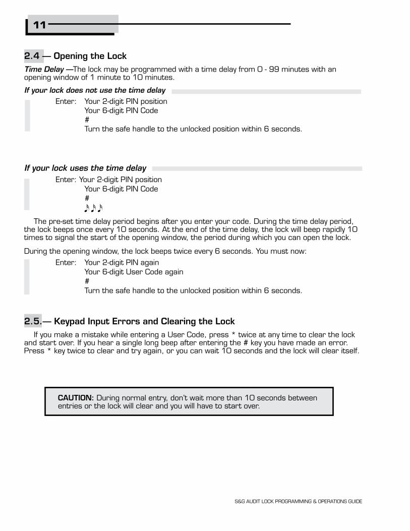
CAUTION: During normal entry, don’t wait more than 10 seconds between entries or the lock will clear and you will have to start over.
If your lock uses the time delay Enter: Your 2-digit PIN position Your 6-digit PIN Code #
The pre-set time delay period begins after you enter your code. During the time delay period, the lock beeps once every 10 seconds. At the end of the time delay, the lock will beep rapidly 10 times to signal the start of the opening window, the period during which you can open the lock.
During the opening window, the lock beeps twice every 6 seconds. You must now:
Enter: Your 2-digit PIN again Your 6-digit User Code again # Turn the safe handle to the unlocked position within 6 seconds.
2.5.— Keypad Input Errors and Clearing the LockIf you make a mistake while entering a User Code, press * twice at any time to clear the lock
and start over. If you hear a single long beep after entering the # key you have made an error. Press * key twice to clear and try again, or you can wait 10 seconds and the lock will clear itself.
2.4 — Opening the LockTime Delay —The lock may be programmed with a time delay from 0 - 99 minutes with an opening window of 1 minute to 10 minutes.
If your lock does not use the time delay Enter: Your 2-digit PIN position Your 6-digit PIN Code # Turn the safe handle to the unlocked position within 6 seconds.

S&G AUDIT LOCK PROGRAMMING & OPERATIONS GUIDE
2.6 — Penalty TimeIf you enter 5 incorrect codes in a row, the lock goes into a 10-minute penalty time and cannot be opened. Once in penalty time, additional input does not affect the lock, and you must wait 10 minutes before any valid code entry will be accepted.
2.7 — Bolt Extension IndicatorWhen the lock bolt extends to the locked position, you will hear one double-beep
(low then high pitch).
2.8 — Keypad Tamper Indicator (optional)The lock records each time the keypad housing is unseated or removed from the base. If the
housing is disturbed, the keypad tamper indicator beeps the SOS warning (3 short/high pitch beeps; 3 short/low pitch beeps; 3 short/high pitch beeps) the next time you enter a valid access code.
The lock will not open at this point. The SOS signal is repeated twice. When it stops, enter a valid code within one minute to reset the keypad tamper indicator and open the lock.
The keypad will not work when disconnected from the base. If the lock is in Manager/Employee mode, it may have to be re-enabled by a Manager or Supervisor code.
12

13
S&G AUDIT LOCK PROGRAMMING & OPERATIONS GUIDE
2.9 — Low Battery IndicatorIf you enter a correct User Code and hear 5 double-beeps when the lock opens, the batteries
are low. Change the batteries.
If the batteries are so low the lock can’t work properly, the lock beeps 20 times when a User code is entered. The lock will not open. Change the batteries right away and re-enter a User code to open the lock.
The 9V batteries are located behind the keypad.
2.10 — Changing the BatteriesThe lock will not lose any codes or program settings while you replace the batteries.
Your lock uses two 9-volt alkaline batteries. We recommend Duracell® alkaline batteries.
To change the batteries, carefully remove the keypad housing by lifting the bottom edge (closest to the S&G logo) and easing it off the base. Detach the old batteries from the terminals. Insert the new batteries, supporting the top of each battery holder with your other hand to prevent bending or breaking the holder.
2.11 — iButton Touch Key
The touch key allows you to transfer the audit trail from the lock to your computer. The audit trail is a time and date stamped record of all lock activity.
For more instructions on downloading the audit trail see Section 3.2 on page 15 of this manual.

14
S&G AUDIT LOCK PROGRAMMING & OPERATIONS GUIDE
3.1 — Command 22: Changing a PIN CodeUse Command 22 to change your own PIN Code. Always leave the safe door open while
changing codes. When changing a User Code, you will enter both the 2-digit PIN position and the 6-digit PIN Code. The PIN position does not change.
To change a PIN Code, perform the following steps (A PIN Code can contain any numbers/letters except # or *):
Step 1. Enter: 2 2 *
Step 2. Enter: 2-digit PIN position Current 6-digit PIN Code # Step 3. Enter: 2-digit PIN position New 6-digit PIN Code # Step 4. Enter: 2-digit PIN position again
New 6-digit PIN Code again # Try the new PIN Code at least three times to confirm operation before closing the safe door..
These programming commands allow you to perform a variety of lock functions.
Command . . . . . . . . . Description/Function
2 2 * . . . . . . . . . . . . .Change PIN Code.
2 8 * . . . . . . . . . . . . .Download the Audit Trail.
3 2 * . . . . . . . . . . . . .Set Mode of Operation.
3 8 * . . . . . . . . . . . . .Enable/Disable Duress—Duress Module required.
4 3 * . . . . . . . . . . . . .Identify the type of lock.
7 3 * . . . . . . . . . . . . .Set date.
7 4 * . . . . . . . . . . . . .Add or delete User PIN Codes & Set Time Delay.
7 7 * . . . . . . . . . . . . .Verify PIN position.
7 8 * . . . . . . . . . . . . .Set time.
PROGRAMMING THE LOCK3.
15
S&G AUDIT LOCK PROGRAMMING & OPERATIONS GUIDE
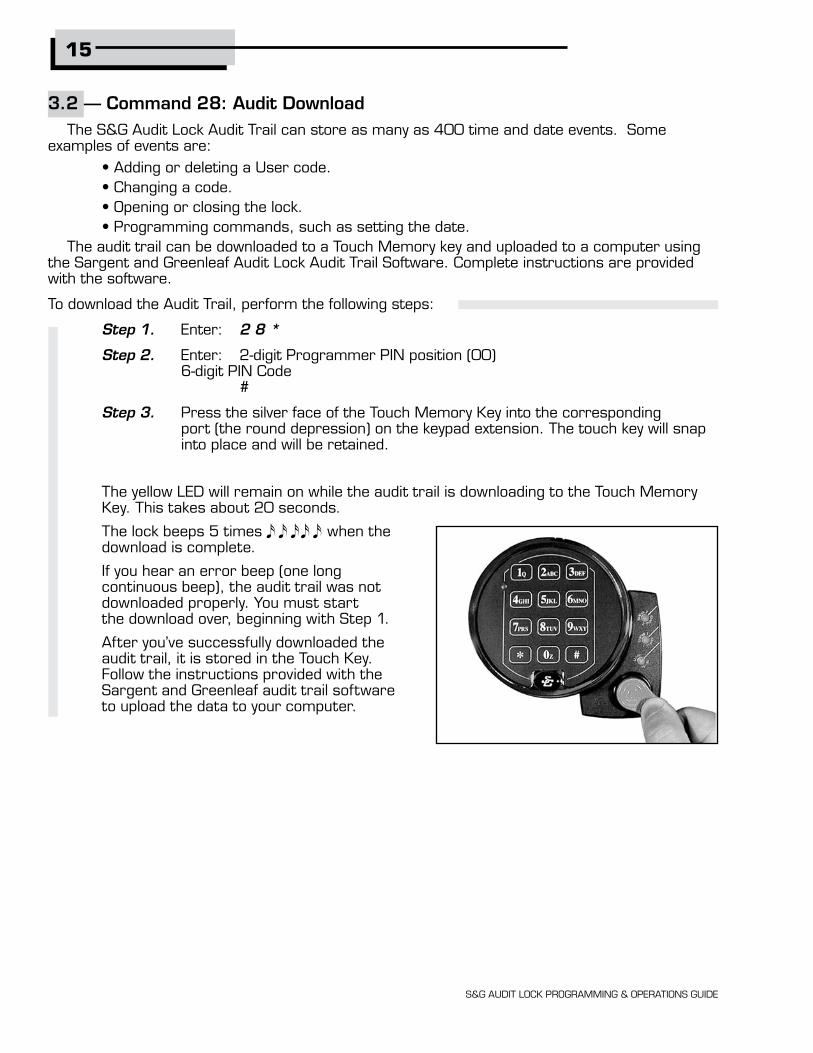
3.2 — Command 28: Audit DownloadThe S&G Audit Lock Audit Trail can store as many as 400 time and date events. Some
examples of events are: • Adding or deleting a User code. • Changing a code. • Opening or closing the lock. • Programming commands, such as setting the date.
The audit trail can be downloaded to a Touch Memory key and uploaded to a computer using the Sargent and Greenleaf Audit Lock Audit Trail Software. Complete instructions are provided with the software.
To download the Audit Trail, perform the following steps:
Step 1. Enter: 2 8 *
Step 2. Enter: 2-digit Programmer PIN position (00) 6-digit PIN Code #
Step 3. Press the silver face of the Touch Memory Key into the corresponding port (the round depression) on the keypad extension. The touch key will snap into place and will be retained.
The yellow LED will remain on while the audit trail is downloading to the Touch Memory Key. This takes about 20 seconds.
The lock beeps 5 times when the download is complete.
If you hear an error beep (one long continuous beep), the audit trail was not downloaded properly. You must start the download over, beginning with Step 1.
After you’ve successfully downloaded the audit trail, it is stored in the Touch Key. Follow the instructions provided with the Sargent and Greenleaf audit trail software to upload the data to your computer.

16
S&G AUDIT LOCK PROGRAMMING & OPERATIONS GUIDE
3.3 — Command 43: Identifying the Type of LockAt times, a service technician may need to know what type of lock is mounted on the safe
door.
To identify the lock, perform the following 2 steps:
Step 1. Enter: 4 3 *
Step 2. Listen for the three sets of beeps. Use the table below to determine the type of lock.
Beep Set Number of Beeps
1st set (high pitch) 4 5
2nd set (low pitch) 2 2
3rd set (high pitch) 4 4
Type of Lock Standard S&G Audit Lock Push/Pull Bolt Lock
3.4 — Command 73: Set DateYou must set the date in order to use the audit trail function. The date should be entered in DDMMYY format, where DD = day, MM = month, and YY = year. The Date should be set when the lock is first set up and prepared for use. To set the date, perform the following steps:
Step 1. Enter: 7 3 *
Step 2. Enter: 2-digit Programmer PIN position (00) 6-digit PIN Code # Step 3. Enter: 2-digit Manager or Supervisor PIN position (01-09) 6-digit PIN Code # Step 4. Enter: Date in DDMMYY format # Step 5. Enter: Confirm date by entering it again in DDMMYY format #

17
S&G AUDIT LOCK PROGRAMMING & OPERATIONS GUIDE
ExampleTo set the date as July 4, 2000 (using the factory default Codes): Step 1. Enter: 7 3 *
Step 2. Enter: 0 0 1 2 3 4 5 6 # Step 3. Enter: 0 2 0 2 0 2 0 2 # Step 4. Enter: 0 4 0 7 0 0 # Step 5. Enter: 0 4 0 7 0 0 # 3.5 — Command 74: Add or Delete Code Positions Add a New User Position To add or delete User positions, perform the following steps: Step 1. Enter: 7 4 * Step 2. Enter: 2-digit Manager PIN position (01, 02, or 03) 6-digit PIN Code # Step 3. Enter: New 2-digit PIN position A 6-digit PIN Code # Step 4. Enter: New PIN position again to confirm 6-digit PIN Code again to confirm # After a User has been assigned a PIN position and a PIN Code, we recommend that each User change his or her PIN Code using Command 22.

18
S&G AUDIT LOCK PROGRAMMING & OPERATIONS GUIDE
Example
Add PIN position 14 (using the factory default codes). Note that for the new User you can assign any PIN Code as long as it does not contain * or # as one of the digits.
Step 1. Enter: 7 4 *
Step 2. Enter: 0 2 0 2 0 2 0 2 # Step 3. Enter: 1 4 1 4 1 4 1 4 #
Step 4. Enter: 1 4 1 4 1 4 1 4 # The User should now change his PIN Code using Command 22.
Delete a User
To delete a User you only need to know his 2-digit PIN position and perform the following steps. Step 1. Enter: 7 4 *
Step 2. Enter: 2-digit Manager or Supervisor PIN position. 6-digit PIN Code # Step 3. Enter: 2-digit PIN position to be deleted # Step 4. Enter: 2-digit PIN position again to confirm # Example
Delete the User for PIN 14.
Step 1. Enter: 7 4 *
Step 2. Enter: 0 2 0 2 0 2 0 2 # Step 3. Enter: 1 4 # Step 4. Enter: 1 4 #
19
S&G AUDIT LOCK PROGRAMMING & OPERATIONS GUIDE
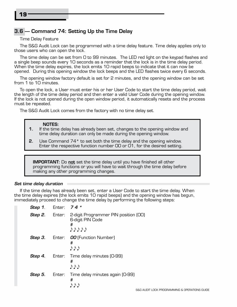
3.6 — Command 74: Setting Up the Time DelayTime Delay Feature
The S&G Audit Lock can be programmed with a time delay feature. Time delay applies only to those users who can open the lock.
The time delay can be set from 0 to 99 minutes. The LED red light on the keypad flashes and a single beep sounds every 10 seconds as a reminder that the lock is in the time delay period. When the time delay expires, the lock emits 10 rapid beeps to indicate that it can now be opened. During this opening window the lock beeps and the LED flashes twice every 6 seconds.
The opening window factory default is set for 2 minutes, and the opening window can be set from 1 to 10 minutes.
To open the lock, a User must enter his or her User Code to start the time delay period, wait the length of the time delay period and then enter a valid User Code during the opening window. If the lock is not opened during the open window period, it automatically resets and the process must be repeated.
The S&G Audit Lock comes from the factory with no time delay set.
Set time delay duration
If the time delay has already been set, enter a User Code to start the time delay. When the time delay expires (the lock emits 10 rapid beeps) and the opening window has begun, immediately proceed to change the time delay by performing the following steps:
Step 1. Enter: 7 4 *
Step 2. Enter: 2-digit Programmer PIN position (00) 6-digit PIN Code #
Step 3. Enter: 00 (Function Number) #
Step 4. Enter: Time delay minutes (0-99) #
Step 5. Enter: Time delay minutes again (0-99) #
NOTES:1. If the time delay has already been set, changes to the opening window and time delay duration can only be made during the opening window.
2. Use Command 74* to set both the time delay and the opening window. Enter the respective function number 00 or 01, for the desired setting.
IMPORTANT: Do not set the time delay until you have finished all other programming functions or you will have to wait through the time delay before making any other programming changes.

20
S&G AUDIT LOCK PROGRAMMING & OPERATIONS GUIDE
Example
To set the time delay to 10 minutes:
Step 1. Enter: 7 4*
Step 2. Enter: 0 0 (PC 2 digit position) 1 2 3 4 5 6 # (PC 6 digit Code)
Step 3. Enter: 0 0 # (Function Number)
Step 4. Enter: 1 0 # (Number of Minutes Time Delay)
Step 5. Enter: 1 0 # (Number of Minutes Time Delay)
To eliminate the time delay period, simply enter zero (0) for the time delay minutes.
Changing the opening window duration
If the time delay has already been set, enter a User Code to start the time delay. When the time delay expires (the lock emits 10 rapid beeps) and the opening window has begun, immediately proceed to set the opening window minutes by performing the following steps:
Step 1. Enter: 7 4 *
Step 2. Enter: 2-digit Programmer PIN position (00) 6-digit PIN Code # Step 3. Enter: 0 1 (Function Number) #
Step 4. Enter: Opening window minutes (1-10) #
Step 5. Enter: Opening window minutes again (1-10) #

21
S&G AUDIT LOCK PROGRAMMING & OPERATIONS GUIDE
Example
To set the opening window to 5 minutes:
Step 1. Enter: 74*
Step 2. Enter: 0 0 (PC 2 digit pin position) 1 2 3 4 5 6 # (PC 6 digit pin Code) Step 3. Enter: 0 1 # (Function Number) Step 4. Enter: 5 # (Number of Minutes For Opening Window) Step 5. Enter: 5 # (Number of Minutes For Opening Window) If time delay has not been previously set, the setting of time delay may begin immediately upon input of the correct code sequence.
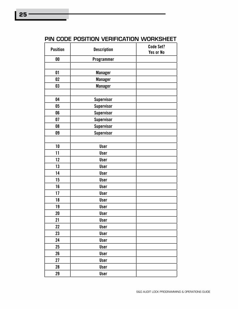
3.7 — Command 77: PIN Position VerificationUse this code to verify that a User has been assigned to a PIN position. For example, it will tell
you whether PIN 07 has a PIN Code in this position. In order to manage the PIN User Codes, the attached PIN Code Position Verification Worksheet is recommended (see page 25).
Step 1. Enter: 7 7 *
Step 2. Enter: PIN position to be verified and #
One long beep means no Code is set for that position. One short beep means a Code is set.

22
S&G AUDIT LOCK PROGRAMMING & OPERATIONS GUIDE
3.8 — Command 78: Set TimeYou must set the time in order to use the audit trail function. The time should be set in HHmm
format based on a 24-hour clock, where HH = hours and mm = minutes. The time should be set when the lock is first set up. The time is to always be set in the local standard time. Local standard time must be set even though daylight savings time may be in effect. To set time perform the following steps:
Step 1. Enter: 7 8 *
Step 2. Enter: 2-digit Programmer PIN position (00) 6-digit PIN Code #
Step 3. Enter: 2-digit Manager or Supervisor PIN position (01- 09 PIN positions only) 6-digit PIN Code # Step 4. Enter: Time in HHmm format # Step 5. Enter: Time in HHmm format again to confirm # Example
To set the time as 3:15 p.m., becoming 15:15 (using the factory default Codes):
Step 1. Enter: 7 8 *
Step 2. Enter: 0 0 1 2 3 4 5 6 # Step 3. Enter: 0 2 0 2 0 2 0 2 #
Step 4. Enter: 1 5 1 5 # Step 5. Enter: 1 5 1 5 #
3.9 — Command 38: Setting the Duress Alarm FeatureThe model 6128/6129 lock has an optional duress, or silent alarm, option. The optional
duress module must be connected to the lock and your alarm system for this feature to work.

S&G AUDIT LOCK PROGRAMMING & OPERATIONS GUIDE
Using the Duress Alarm Feature
To send a duress alarm to the alarm center, enter a User Code that is one number higher or lower on the last number of a User’s normal PIN Code and press the # key.
For example, if the normal User Code is 123456 for PIN position 02, the User can activate the duress alarm by entering 02123455 or 02123457, followed by #. If the User Code ends in 0, use 1 or 9 to activate the duress alarm. The lock will operate normally when a Duress code is entered.
All User Codes can send the duress signal at any time. It can also be sent during programming sequences.
Enable the Duress Alarm Feature
After the lock is installed with the module, the duress feature must be enabled by performing the following steps:
Step 1. Enter: 3 8 *
Step 2. Enter: 2-digit Programmer or Manager PIN position (00 - 03) 6-digit PIN Code # Step 3. Enter: 1 (Function Number) # Step 4. Enter: 1 (Function Number) #
The lock can now send a duress signal through the interface module.
Disabling the Duress Alarm Feature
The duress feature can be disabled without disconnecting the duress module, by performing the following steps:
Step 1. Enter: 3 8 *
Step 2. Enter: 2-digit Programmer or Manager PIN position (00 - 03) 6-digit PIN Code # (continued on next page)
23

S&G AUDIT LOCK PROGRAMMING & OPERATIONS GUIDE
Step 3. Enter: 0 (Function Number) # Step 4. Enter: 0 (Function Number) #
24
25
S&G AUDIT LOCK PROGRAMMING & OPERATIONS GUIDE
Position DescriptionCode Set?Yes or No
00 Programmer
01 Manager02 Manager03 Manager
04 Supervisor05 Supervisor06 Supervisor07 Supervisor08 Supervisor09 Supervisor
10 User11 User12 User13 User14 User15 User16 User17 User18 User19 User20 User21 User22 User23 User24 User25 User26 User27 User28 User29 User
PIN CODE POSITION VERIFICATION WORKSHEET
26
S&G AUDIT LOCK PROGRAMMING & OPERATIONS GUIDE
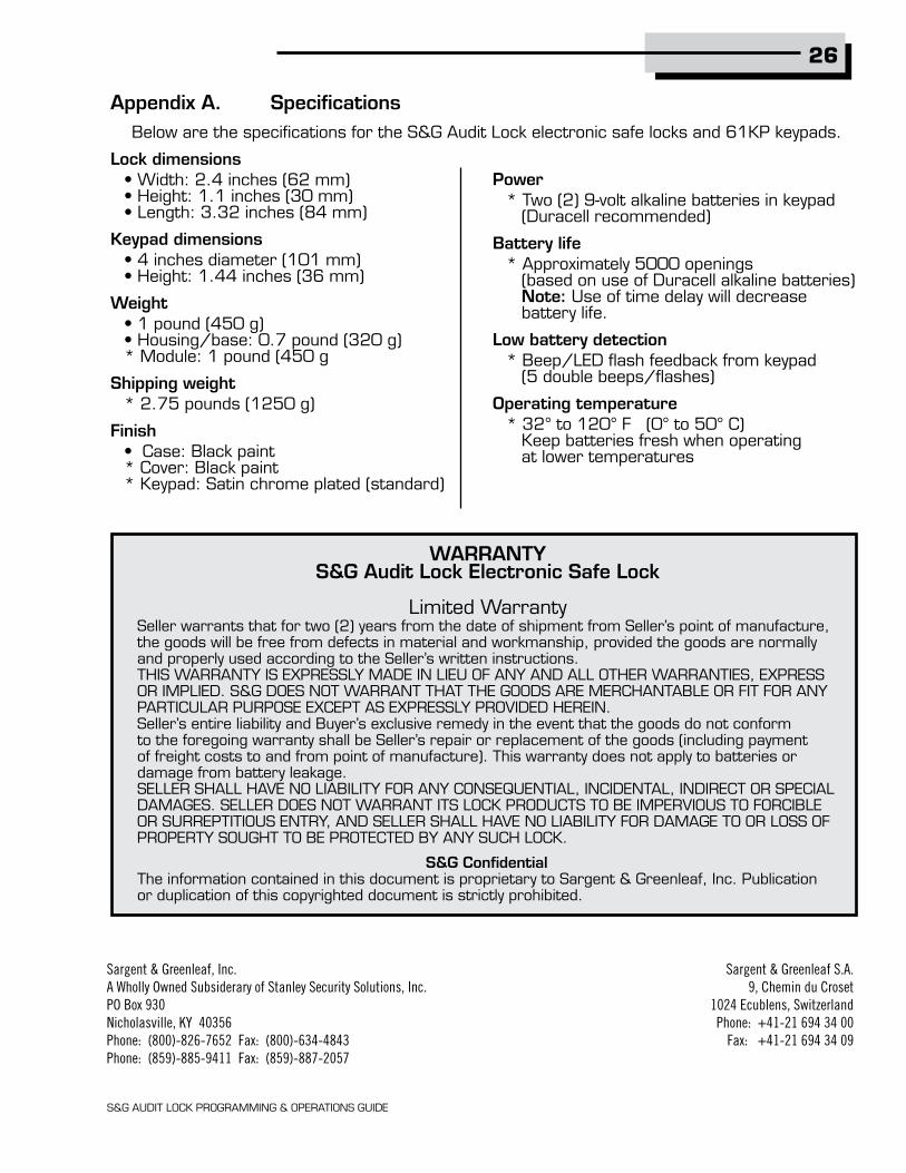
Appendix A. SpecificationsBelow are the specifications for the S&G Audit Lock electronic safe locks and 61KP keypads.
Lock dimensions • Width: 2.4 inches (62 mm) • Height: 1.1 inches (30 mm) • Length: 3.32 inches (84 mm)
Keypad dimensions • 4 inches diameter (101 mm) • Height: 1.44 inches (36 mm)
Weight • 1 pound (450 g) • Housing/base: 0.7 pound (320 g) * Module: 1 pound (450 g
Shipping weight * 2.75 pounds (1250 g)
Finish • Case: Black paint * Cover: Black paint * Keypad: Satin chrome plated (standard)
Power * Two (2) 9-volt alkaline batteries in keypad (Duracell recommended)
Battery life * Approximately 5000 openings (based on use of Duracell alkaline batteries) Note: Use of time delay will decrease battery life.
Low battery detection * Beep/LED flash feedback from keypad (5 double beeps/flashes)
Operating temperature * 32° to 120° F (0° to 50° C) Keep batteries fresh when operating at lower temperatures
Seller warrants that for two (2) years from the date of shipment from Seller’s point of manufacture, the goods will be free from defects in material and workmanship, provided the goods are normally and properly used according to the Seller’s written instructions.THIS WARRANTY IS EXPRESSLY MADE IN LIEU OF ANY AND ALL OTHER WARRANTIES, EXPRESS OR IMPLIED. S&G DOES NOT WARRANT THAT THE GOODS ARE MERCHANTABLE OR FIT FOR ANY PARTICULAR PURPOSE EXCEPT AS EXPRESSLY PROVIDED HEREIN.Seller’s entire liability and Buyer’s exclusive remedy in the event that the goods do not conform to the foregoing warranty shall be Seller’s repair or replacement of the goods (including payment of freight costs to and from point of manufacture). This warranty does not apply to batteries or damage from battery leakage.SELLER SHALL HAVE NO LIABILITY FOR ANY CONSEQUENTIAL, INCIDENTAL, INDIRECT OR SPECIAL DAMAGES. SELLER DOES NOT WARRANT ITS LOCK PRODUCTS TO BE IMPERVIOUS TO FORCIBLE OR SURREPTITIOUS ENTRY, AND SELLER SHALL HAVE NO LIABILITY FOR DAMAGE TO OR LOSS OF PROPERTY SOUGHT TO BE PROTECTED BY ANY SUCH LOCK.
S&G ConfidentialThe information contained in this document is proprietary to Sargent & Greenleaf, Inc. Publication or duplication of this copyrighted document is strictly prohibited.
WARRANTYS&G Audit Lock Electronic Safe Lock
Limited Warranty
Sargent & Greenleaf, Inc.A Wholly Owned Subsiderary of Stanley Security Solutions, Inc.PO Box 930Nicholasville, KY 40356Phone: (800)-826-7652 Fax: (800)-634-4843Phone: (859)-885-9411 Fax: (859)-887-2057
Sargent & Greenleaf S.A.9, Chemin du Croset
1024 Ecublens, SwitzerlandPhone: +41-21 694 34 00
Fax: +41-21 694 34 09

S&G AUDIT LOCK PROGRAMMING & OPERATIONS GUIDE