samplers and sampling procedures for hazardous waste · pdf filesamplers and sampling...
TRANSCRIPT

EPA-600/2-80-018January 1980
SAMPLERS AND SAMPLING PROCEDURES FOR HAZARDOUS WASTE STREAMS
Emil R. deVera, Bart P. Simmons,Robert D. Stephens and David L. Storm
California Department of Health ServicesBerkeley, California 94704
Grant No. R804692010
Project Officer
Richard A. CarnesSolid and Hazardous Waste Research DivisionMunicipal Environmental Research Laboratory
Cincinnati, Ohio 45268
MUNICIPAL ENVIRONMENTAL RESEARCH LABORATORYOFFICE OF RESEARCH AND DEVELOPMENT
U.S. ENVIRONMENTAL PROTECTION AGENCYCINCINNATI, OHIO 45268

DISCLAIMER
This report has been reviewed by the Municipal EnvironmentalResearch Laboratory, U.S. Environmental Protection Agency, and approvedfor publication. Approval does not signify that the contents necessarilyreflect the views and policies of the U.S. Environmental ProtectionAgency, nor does mention of trade names or commercial products constituteendorsement or recommendation for use.
ii

FOREWORD
The Environmental Protection Agency was created because of increasingpublic and government concern about the dangers of pollution to thehealth and welfare of the American people. Noxious air, foul water,and spoiled land are tragic testimony to the deterioration of ournatural environment. The complexity of that environment and the inter-play between its components require a concentrated and integratedattack on the problem.
Research and development is that necessary first step in problem solu-tion and it involves defining the problem, measuring its impact, andsearching for solutions. The Municipal Environmental Research Laboratorydevelops new and improved technology and systems for the prevention,treatment, and management of wastewater and solid and hazardous wastepollutant discharges from municipal and community sources, for thepreservation and treatment of public drinking water supplies, and tominimize the adverse economic, social, health, and aesthetic effects ofpollution. This publication is one of the products of that research;a most vital communications link between the researcher and the usercommunity.
This study involved the development of simple but effective samplingequipment and procedures for collecting, handling, storing, and record-ing of hazardous wastes. A variety of sampling devices were developedand/or selected to meet the needs of those who regulate and managehazardous wastes. Of particular importance is the development of thecomposite liquid waste sampler, the Coliwasa. The sampling proceduresdeveloped were designed to provide maximum protection for the samplecollector, collection of representative samples of the bulk of wastes,and proper containment, identification, preservation, and handling ofthe samples.
Francis T. Mayo, DirectorMunicipal Environmental ResearchLaboratory
iii
ABSTRACT
The goal of this project was to develop simple but effective sampl-ing equipment and procedures for collecting, handling, storing, andrecording samples of hazardous wastes. The report describes a varietyof sampling devices designed to meet the needs of those who regulateand manage hazardous wastes. Particular emphasis is given to thedevelopment of a composite liquid waste sampler, the Coliwasa. Thissimple device is designed for use on liquid and semi-liquid wastes ina variety of containers, tanks, and ponds. Devices for sampling solidsand soils are also described.
In addition to the sampling devices, the report describes pro-cedures for development of a sampling plan, sample handling, safetyprecautions, proper recordkeeping and chain of custody, and samplecontainment, preservation, and transport. Also discussed are certainlimitations and potential sources of error that exist in the samplingequipment and the procedures. The statistics of sampling are coveredbriefly, and additional references in this area are given.
This report was submitted in partial fulfillment of Research GrantNo. R804692010 by the California Department of Health Services undersponsorship of the U.S. Environmental Protection Agency.

Foreword . . . . . . . . . . . . . . . . . . . . . . . . . . . iiiAbstract . . . . . . . . . . . . . . . . . . . . . . . . . . . ivFigures . . . . . . . . . . . . . . . . . . . . . . . . . . . viTables . . . . . . . . . . . . . . . . . . . . . . . . . . . vii
1. Introduction . . . . . . . . . .2. Conclusions . . . . . . . . . . .3. Recommendations . . . . . . . .4. Samplers . . . . . . . . .
Composite liquid waste sampler .Solid Waste samplers . . . . . .Soil samplers . . . . . .Procedure for use . . . . . .Pond sampler . . . . . .
5. Preparation for Sampling ... . .6. Sampling Procedures . . . . .
General considerations . . . . .Sampler handling . . . . .Field log book . . . . .Chain of custody record . . . .Sample analysis request sheet .Sample delivery to the laboratoryShipping of sample
7. Receipt and Logging of Sample8. Preservation and Storage of Samples
. . . . . . . . . . .
. . . . . . . . . . .
. . . . . . . . . . .
. . . . . . . . . . .
. . . . . . . . . . .
. . . . . . . . . . .
. . . . . . . . . . .
. . . . . . . . . . .
. . . . . . . . . . .
. . . . . . . . . . .
. . . . . . . . . . .
. . . . . . . . . . .
. . . . . . . . . . .
. . . . . . . . . . .
. . . . . . . . . . .
. . . . . . . . . . .
. . . . . . . . . . .
. . . . . . . . . . .
. . . . . . . . . . .
. . . . . . . . . . .
134559
1314202426263941424242454648
References . . . . . . . . . . .. . . . . 50Appendices . . . . . .. . . . . . . . . 52
A. Development of the composite liquid . . . . . . . . . . . 52waste sampler (Coliwasa) . . . . . . . . . . . . . .
B. Parts for constructing the coliwasa . . . . . . . . . . . 62C. Checklist of items required in the field . . . . . . . 63
sampling of hazardous wastes . . . . . . . . . . . . D. Random sampling . . . . . . . . . . . . . . . . 67E.. Systematic errors in using the coliwasa . . . . . . . . . 68

FIGURES
Number123456789
1011121314
A-lA-2A-3A-4A-5
Composite liquid waste sampler (Coliwasa)Grain sampler . . . . . . . . . . . . .Sampling trier . . . . . . . . . . . . .Trowel or scoop with calibrations . . .Soil auger . . . . . . . . . . . . .Veihmeyer sampler . . . . . . . . . . .Waste pile sampler . . . . . . . . . . .Pond sampler . . . . . . . . . . .Weighted bottle sampler . . . . . . . .Example of waste manifest . . . . . . .Official sample label . . . . . . .Example of official sample seal . . . .Example of chain of custody record . . .Example of hazardous waste sample
analysis request sheet . . . . . . .Coliwasa, Model 1 . . . . . . .Coliwasa, Model 2 . . . . . . .Coliwasa, Model 3 . . . . . . .Coliwasa, Model 4 . . . . . . .Coliwasa, Model 5 . . . . . . .
. . . 6
. . . 10
. . . 11
. . . 13
. . . 15
. . . 16
. . . 20
. . . 21
. . . 23
. . . 28
. . . 40
. . . 40
. . . 43
. . . 44
. . . 53
. . . 55
. . . 56
. . . 58
. . . 58
vi
Number
12
34
5
67
8A-l
A-2
TABLES
Page
Basic Parts and Costs of a Veihmeyer Soil Sampler . . . 17Basic Parts and Approximate Costs of aPond Sampler . . . . . . . . . . . . . . . . . . 21
Samplers Recommended for Various Types of Waste . . . . 29Sample Containers and Closures Recommended
for Various Types of Waste . . . . . . . . . . . . . 31Sampling Points Recommended for Most Waste
Containers . . . . . . . . . . . . . 32Number of Samples to be Collected . . . . . . . . . . . 34Respiratory Protective Devices Recommended
for Various Hazards . . . . . . . . . . . . . . . . . 35Methods of Preservation for Hazardous Wastes . . . . . 49Relative Volumes of Liquids in theTwo-Phase Mixture . . . . . . . . . . . . . . . . . 60
Relative Volumes of Liquids in theThree-Phase Mixture . . . . . . . . . . . . . . . . . 60
APPENDIX B. Parts for Constructing the Coliwasa . . . . . . . . . 62APPENDIX C. Checklist of Items Required in the
Field Sampling of Hazardous Wastes. . . 63, 64, 65, 66APPENDIX D.RandomSamplingAPPENDIX E-l Sample Volume
. . . . . . . . . . . . . . . . . .67
. . . . . . . . . . . . . . . . .
vii

SECTION 1
INTRODUCTION
The growth in the size and complexity of industry and the imple-mentation of air and waste pollution abatement technology has confrontedthe nation with the immensely difficult problem of managing large volumesof waste products that are often toxic, flammable, corrosive, and explo-sive. The problem is further exacerbated by the complexity of the waste.This difficult situation is now being addressed at many levels of govern-ment through a variety of regulatory agencies. Solution is being soughtthrough a "cradle-to-grave" regulation of waste generation, transport,reprocessing, and disposal. Significant progress toward a solution isalso being made by the private waste management industry with improvedtechniques in handling, resource recovery, and disposal.
The management of hazardous wastes may be addressed primarily as achemical problem. With this approach, management decisions must befounded on proper knowledge of waste chemical compositions. Definingthe information needed on waste composition to support managementdecisions presents an additional complication, for such informationvaries with waste type and with handling or disposal objectives. Re-gardless of the details, the required information results from chemicaland physical testing of the waste.
Industrial waste predominantly occurs in volumes that are largeenough to preclude testing or analysis of the entire body of the waste.Obtaining samples adequate in size for the required testing and repre-sentative of the bulk volumes of the wastes is therefore necessary.The obtainment of such representative samples presents special problem,for many wastes are complex, multiphase mixtures that vary greatly inviscosity, corrosivity, volatility, flammability, or capability togenerate toxic gases.
This study was conducted to develop specialized equipment and pro-cedures designed to handle the widest possible variety of waste samplingsituations.
The equipment and procedures that have been developed and describedin this report had their origins in the hazardous waste regulatory pro-gram of the California Department of Health Services. Early in thisprogram, the necessity of reliable analytical data on waste compositionbecame apparent. As a result, the problem of proper sampling of hazardous
1

wastes was addressed. Review of the wide variety of industrial wastesproduced in California revealed that liquids or liquid-sludge mixturesaccounted for the greatest volume of wastes. Most of these materialsat some point are contained and/or transported in tank (vacuum) trucksor barrels. A primary concern, therefore, was to develop the capa-bility for sampling these wastes.
The first prototype of a liquid waste sampler was the tube sampier,which was designated the composite liquid waste sampler or Coliwasa.This sampling device, fabricated from readily available materials, wastaken to the field and tested for its usability and reliability.
The first large-scale sampling of hazardous wastes was conductedjointly by the California Department of Health Services and the Univer-sity of Southern California under the sponsorship of the U.S. Environ-mental Protection Agency (EPA)2 In this sampling program, approxi-mately 400 waste samples were collected. These samples varied greatlyin composition and in physical characteristics.
Approximately 90% of all wastes sampled were liquids or sludges andcould be sampled with the Coliwasa. The sampling program established theutility of this sampler. In addition, however, several deficiencies andneeded improvments were demonstrated. Along with the need for liquidsampling equipment, a need was also demonstrated for simple but effectiveequipment for sampling solids, soils, and liquids in large tanks or ponds.This early study also clearly indicated the need for development of goodsafety procedures and sample handling, preservation, and custody procedures.
In November 1976, under a grant from the EPA, the California Depart-ment of Health Services embarked on a development program to establishrecommended procedures and equipment for the sampling of hazardous wastes.Commercially available liquid samplers were investigated, but none wasfound to be adaptable to sampling hazardous wastes. Equipment developmentcentered on the Coliwasa, which had been conceived and initially designedby waste management personnel of the Department. Solid, soil, and pondsampling equipment was obtained after an extensive review of the litera-ture and testing of available equipment for efficiency. Criteria used inchoosing candidate procedures were ready availability, reasonable cost,simplicity of design and operation, and chemical inertness. Candidatemethods and samplers were subjected to laboratory and field tests. Lab-oratory tests for the liquid samplers consisted of sampling water as wellas multiphase waste mixtures. The samplers were examined for leakage,ease of use and transfer, and cross contamination. In field tests, thesamplers for liquids and solids were used on actual wastes existing in avariety of containers, ponds, or soils.
The body of the report gives detailed discussions of recommendedsamplers, preparation for sampling, sampling procedures, sample handling,and recordkeeping. The appendices present a variety of practical supportdata for the body of the report.
SECTION 2
CONCLUSIONS
The present study was designed to develop simple but effectivesampling equipment for collecting represenative samples of hazardouswastes. In addition, recommended procedures for sample collection,handling, storage, and recording were to be developed. These primaryobjectives have been met, and the resulting sampling equipment andprocedures are presented here.
The sampling equipment and procedures were designed to insure thewidest possible applicability in the sampling of various types ofhazardous wastes. The methods, however, are not intended to coverall possible sampling situations. Professional judgment on applica-bility must be exercised.

SECTION 3
RECOMMENDATIONS
The next step in the development of standardized sampling methodsshould be user verfication. Additional data on applicability, reli-ability, and other performance characteristics need to be developedbefore these recommended methods can become standard methods. Thisnext phase will require considerable effort by a large number ofcollaborators, for the methodology described in this report isintended to be satisfactory for essentially the entire waste-producingindustry. Significant benefit is to be gained by both industry andenvironmental regulatory agencies if efficient, reliable hazardouswaste sampling methods can be established. We therefore strongly recommethat work on this validation begin immediately.
nd
4

SECTION 4
SAMPLERS
Sampling of hazardous wastes requires different types of samplers.Some of these samplers are commercially available, but the others haveto be fabricated. This section lists and describes suitable samplers.Their uses and commercial availability as well as directions for theiruse are reported. Directions for fabricating the commercially unavail-able samplers are also outlined.
COMPOSITE LIQUID WASTE Sampler (COLIWASA)
The Coliwasa is the single most important hazardous waste samplerdiscussed in this report. It was chosen from a number of other liquidsamplers, based on laboratory and field tests, as the most practical.It permits the representative sampling of multiphase wastes of a widerange of viscosity, corrosivity, volatility, and solids content. Itssimple design makes it easy to use and allow the rapid collection ofsamples, thus minimizing the exposure of the sample collector to po-tential hazards from the wastes. The sampler is not commerciallyavailable, but it is relatively easy and inexpensive to fabricate. Thecost of fabrication is low enough that the contaminated parts may bediscarded after a single use when they cannot be easily cleaned.
The recommended model of the Coliwasa is shown in Figure 1. Thehistory and development of this sampler is discussed in detail in AppendixA. The main parts of the Coliwasa consist of the sampling tube, theclosure-locking mechanism, and the closure system.
The sampling tube consists of a 1.52-m(5-ft.) by 4.13-cm(1 5/8-in.)I.D. translucent plastic pipe, usually polyvinyl chloride (PVC) or boro-silicate glass plumbing tube. The closure-locking mechanism consists ofa short-length, channeled aluminum bar attached to the sampler's stopperrod by an adjustable swivel. The aluminum bar serves both as a T-handleand lock for the sampler's closure system. When the sampler is inthe open position, the handle is place in the T-position and pusheddown against the locking block. This manipulation pushes out theneoprene stopper and opens the sampling tube. In the close position,the handle is rotated until one leg of the T is squarely perpendicularagainst the locking block. This tightly seats the neoprene stopperagainst the bottom opening of the sampling tube and positively locksthe sampler in the close position. The closure tension can be adjustedby shortening or lengthening the stopper rod by screwing it in or out
5

6

of the T-handle swivel. The closure system of the sampler consists ofa sharply taped neoprene stopper attached to a 0.95-cm (3/8-in.) O.D.rod, usually PVC. The upper end of the stopper rod is connected tothe swivel of the aluminum T-handle. The sharply tapered neoprenestopper can be fabricated according to specifications by plastic productsmanufacturers at an extremely high price, or it can be made in-house bygrinding down the inexpensive stopper with a shop grinder as described inNote 1 of Appendix B.
TWO types of Coliwasa samplers are made, namely plastic or glass.The plastic type consists of translucent plastic (usually PVC) samplingtube. The glass Coliwasa uses borosilicate glass plumbing pipe as thesampling tube and Teflon plastic stopper rod.
The complete list of parts for constructing the two types of Coliwasasamplers is given in Appendix B. The suppliers and approximate costs ofthe parts as well as the directions for fabricating the commerciallyunavailable parts are also given.
The sampler is assembled as shown in Figure 1 and as follows:
1. Attach the. swivel to the T-handle with the 3.18 cm(l¼ in.) longbolt and secure with the 0.48 cm(3/16 in.) National Coarse(NC)washer and lock nut.
2. Attach the neoprene stopper to one end of the stopper rod andsecure with the 0.95 cm(3/8 in.) washer and lock nut.
3. Install the stopper and stopper rod assembly in the sampling tube.
4. Secure the locking block sleeve on the block with glue or screws.This block can also be fashioned by shaping a solid plastic rodon a lathe to the required dimensions.
5. Position the locking block on top of the sampling tube such thatthe sleeveless portion of the block fits inside the tube, thesleeve sits against the top end of the tube, and the upper end ofthe stopper rod slips through the center hole of the block.
6. Attach the upper end of the stopper rod to the swivel of theT-handle.
7. Place the sampler in the close position and adjust the tension onthe stopper by screwing the T-handle in or out.
Uses
The plastic Coliwasa is used to sample most containerized liquidwastes except wastes that contain ketones, nitrobenzene, dimethylforamide,
3,4mesityl oxide, and tetrahydrofuran.
7
The glass Coliwasa is used to sample all other containerized liquidwastes that cannot be sampled with the plastic Coliwasa except strongalkali and hydrofluoric acid solutions.
Procedure for Use
1.
2.
3.
4.
5.
6.
7.
8.
9.
10.
Choose the plastic or glass Coliwasa for the liquid waste to besampled and assemble the sampler as shown in Figure 1.
Make sure that the sampler is clean (see Section 5).
Check to make sure the sampler is functioning properly. Adjustthe locking mechanism if necessary to make sure the neoprenerubber stopper provides a tight closure.
Wear necessary protective clothing and gear and observe requiredsampling precautions (see Section 6).
Put the sampler in the open position by placing the stopper rodhandle in the T-position and pushing the rod down until the handlesits against the sampler's locking block.
Slowly lower the sampler into the liquid waste. (Lower the samplerat a rate that permits the levels of the liquid inside and outsidethe sampler tube to be about the same. If the level of the liquidin the sampler tube is lower than that outside the sampler, thesampling rate is too fast and will result in a nonrepresentativesample).
When the sampler stopper hits the bottom of the waste container,push the sampler tube downward against the stopper to close thesampler. Lock the sampler in the close position by turning the Thandle until it is upright and one end rests tightly on the lockingblock.
Slowly withdraw the sampler from the waste container with one handwhile wiping the sampler tube with a disposable cloth or rag withthe other hand.
Carefully discharge the sample into a suitable sample container(see Section 6) by slowly opening the sampler. This is done byslowly pulling the lower end of the T handle away from the lockingblock while the lower end of the sampler is positioned in a samplecontainer.
Cap the sample container; attach label and seal; record in fieldlog book; and complete sample analysis request sheet and chain ofcustody record.
11. Unscrew the T handle of the sampler and disengage the lockingblock. Clean sampler on site (see Section 5) or store the con-taminated parts of the sampler in a plastic storage tube forsubsequent cleaning. Store used rags in plastic bags forsubsequent disposal.
12. Deliver the sample to the laboratory for analysis (see Section 6).
SOLID WASTE SAMPLERS
A number of tools are available for sampling solid substances. Themost suitable of these for sampling hazardous solid wastes are the grainsampler, sampling trier, and the trowel or scoop.
Grain Sampler
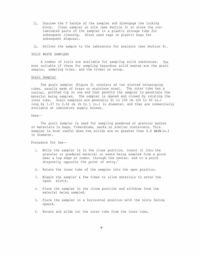
The grain sampler (Figure 2) consists of two slotted telescopingtubes, usually made of brass or stainless steel. The outer tube has aconical, pointed tip on one end that permits the sampler to penetrate thematerial being sampled. The sampler is opened and closed by rotating theinner tube. Grain samplers are generally 61 to 100 cm (24 to 40 in.)long by 1.27 to 2.54 cm (½ to 1 in.) in diameter, and they are commerciallyavailable at laboratory supply houses.
Uses--
The grain sampler is used for sampling powdered or granular wastesor materials in bags, fiberdrums, sacks or similar containers. Thissampler is most useful when the solids are no greater than 0.6 cm (¼ in.)in diameter.
Procedure for Use--
1. While the sampler is in the close position, insert it into thegranular or powdered material or waste being sampled from a pointnear a top edge or comer, through the center, and to a pointdiagonally opposite the point of entry.5
2.
3.
Rotate the inner tube of the sampler into the open position.
Wiggle the sampler a few times to allow materials to enter theopen slots.
4. Place the sampler in the close position and withdraw from thematerial being sampled.
5. Place the sampler in a horizontal position with the slots facingupward.
6. Rotate and slide out the outer tube from the inner tube.

7. Transfer the collected sample in the inner tube into a suitablesample container (see Section 6).
8. Collect two or more core samples at different points (see Section6), and combine the samples in the same container.
9. Cap the sample container; attach label and seal; record in fieldlog book; and complete sample analysis request sheet and chainof custody record.
10. Clean (see Section 5) or store the sampler in plastic bag forsubsequent cleaning.
11. Deliver the sample to the laboratory for analysis (see Section 6).
Figure 2. Grain sampler.
10

Figure 3. Sampling trier.
Sampling trier
A typical sampling trier (Figure 3) is a long tube with a slot thatextends almost its entire length. The tip and edges of the tube slot aresharpened to allow the trier to cut a core of the material to be sampledwhen rotated after insertion into the material. Sampling triers areusually made of stainless steel with wooden handles. They are about 61to 100 cm (24 to 40 in.) long and 1.27 to 2.54 cm (½ to 1 in.) in diameter.They can be purchased readily from laboratory supply houses.
Uses--
The use of the trier is similar to that of the grain sampler dis-cussed above. It is preferred over the grain sampler when the powdered or
11

granular material to be sampled is moist or sticky.
In addition, the sampling trier can be used to obtain soft or loosenedsoil samples up to a depth of 61 cm(24 in.) as outlined below.
Procedure for Use--
1. Insert the trier into the waste material at a 0 to 45O angle fromhorizontal. This orientation minimizes the spillage of samplefrom the sampler. Extraction of samples might require tilting ofthe containers.
2. Rotate the trier once or twice to cut a core of material.
3. Slowly withdraw the trier, making sure that the slot is facingupward.
4. Transfer the sample into a suitable container (see Section 6) withthe aid of a spatula and/or brush.
5. Repeat the sampling at different points (see Section 6). Two ormore times and combine the samples in the same sample container.
6. Cap the sample container; attach the label and seal; record infield log book; and complete sample analysis request sheet andchain of custody record.
7. Wipe the sampler clean, or store it in a plastic bag for subsequentcleaning.
8. Deliver the sample to the laboratory for analysis (see Section 6).
Trowel or Scoop
A garden-variety trowel looks like a small shovel (Figure 4). Theblade is usually about 7 by 13 cm(3 by 5 in.) with a sharp tip. A labor-atory scoop is similar to the trowel, but the blade is usually more curvedand has a closed upper end to permit the containment of material. scoopscome in different sizes and makes. Stainless steel or polypropylene scoopswith 7 by 15-cm(2 3/4 by 6-in.) blades are preferred. A trowel can bebought from hardware stores; the scoop can be bought from laboratory supplyhouses.
Uses--
An ordinary zinc-plated garden trowel can be used in some cases forsampling dry granular or powdered materials in bins or other shallow con-tainers. The laboratory scoop, however, is a superior choice. It isusually made of materials less subject to corrosion or chemical reactions,thus lessening the probability of sample contamination.
12
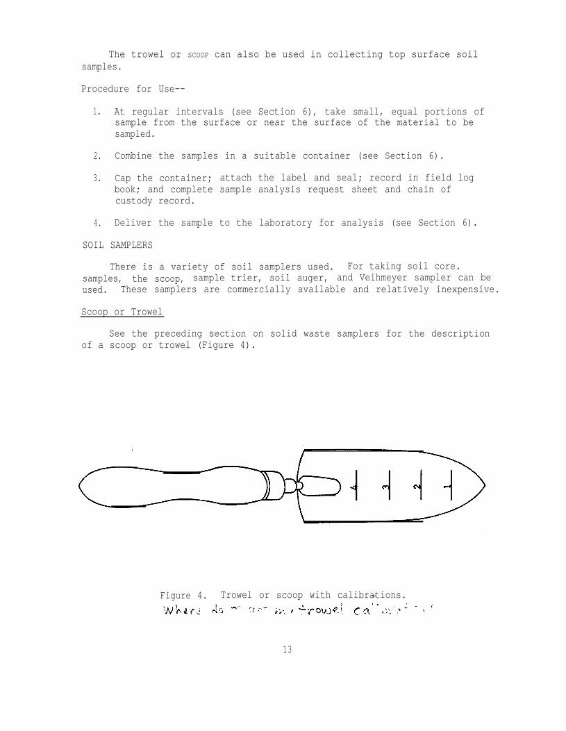
The trowel or SCOOP can also be used in collecting top surface soilsamples.
Procedure for Use--
1. At regular intervals (see Section 6), take small, equal portions ofsample from the surface or near the surface of the material to besampled.
2. Combine the samples in a suitable container (see Section 6).
3. Cap the container; attach the label and seal; record in field logbook; and complete sample analysis request sheet and chain ofcustody record.
4. Deliver the sample to the laboratory for analysis (see Section 6).
SOIL SAMPLERS
There is a variety of soil samplers used. For taking soil core.samples, the scoop, sample trier, soil auger, and Veihmeyer sampler can beused. These samplers are commercially available and relatively inexpensive.
Scoop or Trowel
See the preceding section on solid waste samplers for the descriptionof a scoop or trowel (Figure 4).
Figure 4. Trowel or scoop with calibrations.
13

Uses--
The SCOOP is used to collect soil samples up to 8 cm(3 in.) deep.It is simple to use, but identical mass sample units for a composite sampleare difficult to collect with this sampler. The procedure for use of thescoop is outlined in the preceding section on solid waste samplers.
Sampling Trier
See the preceding section on solid waste samplers for the descriptionof a sampling trier (Figure 3).
Uses--
This sampler can be used to collect soil samples at a depth greaterthan 8 cm(3 in.). The sampling depth is determined by the hardness andtypes of soil being sampled. This sampler can be difficult to use instony, dry, very heavy, or sandy soil. The collected sample tends to beslightly compacted, but this method permits observation of the core samplebefore removal.6
Procedure for Use--
Procedure for use of the sampling trier can be found in the sectionon solid waste samplers.
Soil Auger
This tool consists of a hard metal central shaft and sharpened spiralblades (Figure 5). When the tool is rotated clockwise by its woodenT handle, it cuts the soil as it moves forward and discharges most of theloose soil upward. The cutting diameter is about 5 cm(2 in.). The lengthis about 1 m(40 in.), with graduations every 15.2 cm(6 in.). The lengthcan be increased up to 2 m(80 in.). This tool can be bought from storesand, in some cases, from laboratory supply houses.
Uses--
The auger is particularly useful in collecting soil samples at depthsgreater than 8 cm(3 in.). This sampler destroys the structure of cohesivesoil and does not distinguish between samples collected near the surfaceor toward the bottom. It is not recommended, therefore, when an undis-turbed soil sample is desired.
Procedure for Use--
1. Select the sampling point (see Section 6) and remove unnecessaryrocks, twigs, and other non-soil materials.
14

2. Install the sampler's wooden T handle in its socket.
3. Bore a hole through the middle of an aluminum pie pan large enough toallow the blades of the auger to pass through. The pan will be usedto catch the sample brought to the surface by the auger.
4. Spot the pan against the selected sampling point.
5. Start augering through the hole in the pan until the desired samplingdepth is reached.
6. Back off the auger and transfer the sample collected in the catch panand the sample adhering to the auger to a suitable container (seeSection 6). Spoon out the rest of the loosened sample with a sampling.trier.
7. Repeat the sampling at different sampling points (see Section 6), andcombine the samples in the same container as in step 6.
8. Cap the sample container; attach label and seal; record in field logbook; and complete sample analysis request sheet and chain of cus-tody record.
9. Brush off and wipe the sampler clean, or store it in a plastic bagfor subsequent cleaning.
10. Deliver the sample to the laboratory for analysis (see Section 6).
Figure 5. Soil auger.
15

A. Drive hammer
B. Head
C. Tube
Standard point
Constricted point
Bulge point
Point types
D. Point Puller jack and grip
Figure 6. Veihmeyer sampler
16

Veihmeyer Soil Sampler
This sampler was developed by Professor F.J. Veihmeyer of the Univer-sity of California in Davis.7 The parts of a basic sampler and the corres-ponding costs are given in Table 1, and the basic sampler is shown inFigure 6.
TABLE 1. BASIC PARTS AND COSTS OF A VEIHMEYER SOIL SAMPLER
Parta costb
Tube, 1.5 m (5 ft.) $ 50.40
Tube, 3 m (10 ft.) 84.75
Tip, type A, general use 25.80
Drive head
Drop hammer, 6.8 kg (15 lb.) 71.85
Puller jack and gripC 161.90
Total $ 433.75
a Only one of each part is needed. They are manufactured byHansen Machine Works, 334 N. 12th Street, Sacramento, CA95815.
b Based on August 1, 1977, price list.c Recommended for deep soil sampling.
The tube is chromium-molybdenum steel and comes in various standardlengths from 0.91 to 4.9 m(3 to 16 ft.) and calibrated every 30.48 cm(12in.). Longer tubes can be obtained on special order. Different points(Figure 6) are also available for different types of soil and sampling.Each point is shaped to penetrate specific types of soil without pushingthe soil ahead of it, thus preventing the core from compacting in the tube.The standard point is adequate for most general sampling purposes. Theinside taper of each point is designed to keep the sample from beingsucked out of the tube as it is pulled from the ground. The drive headprotects the top of the tube from deforming when the tube is driven intothe ground with the drive hammer. The hammer doubles as a drive weightand handle when pulling the sampler from the ground. When the sampler tubecannot be pulled easily from the ground, a special puller jack and grip
17

are also available. Specifications for the various parts of the Veihmeyersampler are given as follows:
Points . . . . . Chrome-molly steel, heat-treated. Includes astandard point for general use, a constrictedpoint for deep sampling in heavy clay (keepscore from being sucked out of the tube), abulge point for shallow sampling in heavy clay,and a special point for dry sand. (See Figure6D).
Drive hammer . . Standard weight is 6.8 kg (15 lb.). (See Figure 6A)Tubes . . Chrome-molly steel. Maximum length is 4.9 m
(16 ft.). (See Figure 6C).Head . . Chrome-molly steel, heat-treated. (See Figure 6B).Puller jack . . Cast aluminum frame with steel roller assembly
and handle.Grip . . Chrome-molly steel, heat-treated.
Uses--
The Veihmeyer sampler is recommended for core sampling of most typesof soil. It may not be applicable to sampling stony, rocky, or very wetsoil.
Procedure for Use--
1. Assemble the sampler by screwing in the tip and the drive head onthe sampling tube.
2. Insert the tapered handle (drive guide) of the drive hammer throughthe drive head.
3. Place the sampler in a perpendicular position on the soil to besampled.
4. With the left hand holding the tube, drive the sampler into theground to the desired sampling depth by pounding the drive headwith the drive hammer. Do not drive the tube further than thetip of the hammer's drive guide.
5. Record the length of the tube that penetrated the ground.
6. Remove the drive hammer and fit the keyhole-like opening on the flatside of the hammer onto the drive head. In this position, the ham-mer serves as a handle for the sampler.
18

7. Rotate the sampler at least two revolutions to shear off the sampleat the bottom.
8. Lower the sampler handle (hammer) until it just clears the two ear-like protrusions on the drive head and rotate about 900.
9. Withdraw the sampler from the ground by pulling the handle (hammer)upwards. When the sampler cannot be withdrawn by hand, as in deepsoil sampling, use the puller jack and grip.
10. Dislodge the hammer from the sampler; turn the sampler tube upsidedown; tap the head gently against the hammer; and carefully recoverthe sample from the tube. The sample should slip out easily.
11. Store the core sample, preferably, in a rigid, transparent, or trans-lucent plastic tube when observation of soil layers is to be made.The use of the tube will keep the sample relatively undisturbed. Inother cases, use a lOOO-or 2000-ml (1-qt. or %-gal) sample container(see Section 6) to store the sample.
12. Collect additional core samples at different points (see Section 6).
13. Label the samples; affix the seals; record in the field log book;complete analysis request sheet and chain of custody record; anddeliver the samples to the laboratory for analysis (see Section 6).
Waste Pile Sampler
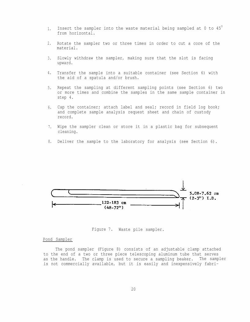
A waste pile sampler (Figure 7) is essentially a large sampling trier.It is commercially available, but it can be easily fabricated from sheetmetal plastic pipe. A polyvinyl chloride plumbing pipe 1.52 m(5 ft) longby 3.2 cm(l¼ in.) I.D. by 0.32 cm(1/8 in.) wall thickness is adequate. Thepipe is sawed lengthwise (about 60/40 split) until the last 10 cm(4 in.)The narrower piece is sawn off and hence forms a slot in the pipe. Theedges of the slot and the tip of the pipe are sharpened to permit thesampler to cut into the waste material being sampled. The unsplit lengthof the pipe serves as the handle. The plastic pipe can be purchased fromhardware stores.
Uses--
The waste pile sampler is used for sampling wastes in large heaps withcross-sectional diameters greater than 1 m(39.4in.). It can also be usedfor sampling granular or powdered wastes or materials in large bins, barges,or silos where the grain sampler or sampling trier is not long enough.This sampler does not collect representative samples when the diameters ofthe solid particles are greater than half the diameter of the tube.
Procedure for Use--
19
1. Insert the sampler into the waste material being sampled at 0 to 45Ofrom horizontal.
20
2. Rotate the sampler two or three times in order to cut a core of thematerial.
3. Slowly withdraw the sampler, making sure that the slot is facingupward.
4. Transfer the sample into a suitable container (see Section 6) withthe aid of a spatula and/or brush.
5. Repeat the sampling at different sampling points (see Section 6) twoor more times and combine the samples in the same sample container instep 4.
6. Cap the container; attach label and seal; record in field log book;and complete sample analysis request sheet and chain of custodyrecord.
7. Wipe the sampler clean or store it in a plastic bag for subsequentcleaning.
8. Deliver the sample to the laboratory for analysis (see Section 6).
Figure 7. Waste pile sampler.
Pond Sampler
The pond sampler (Figure 8) consists of an adjustable clamp attachedto the end of a two or three piece telescoping aluminum tube that servesas the handle. The clamp is used to secure a sampling beaker. The sampleris not commercially available, but it is easily and inexpensively fabri-

cated. The tubes can be readily purchased from most hardware or swimmingpool supply stores. The adjustable clamp and sampling beaker can beobtained from most laboratory supply houses. The materials required tofabricate the sampler are given in Table 2.
Figure 8. Pond sampler.
TABLE 2. BASIC PARTS AND APPROXIMATE COSTS OF A POND SAMPLER
Quantity Item1 Clamp, adjustable, 6.4 to
8.9 cm(2½ to 3½ in.) 'for250-to 600-ml (½ to l½-pt.)beakers
1 Tube, aluminum, heavy duty,telescoping extends 2.5 to4.5 m(8 to 15 ft.) withjoint cam locking mechanism.Pole diameters 2.54 cm(1 in.)I.D. and 3.18 cm(l¼ in.) I.D.
1 Beaker, polypropylene,250-ml (½ pt.)
4 Bolts, 6.35 by 0.64 cm(2¼ by¼ in.) NC
4 Nuts, 0.64 cm(¼ in.) NCTotal
SupplierLaboratory supplyhouses
Olympic Swimming 16.24Pool Co. 807 BuenaVista Street, Alameda,Calif. 94501 or othergeneral swimming poolsupply houses.Laboratory supply 1.00houses.Hardware stores .20
Hardware stores .20$24.64
21
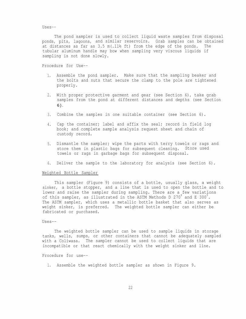
Uses--
The pond sampler is used to collect liquid waste samples from disposalponds, pits, lagoons, and similar reservoirs. Grab samples can be obtainedat distances as far as 3.5 m(.ll½ ft) from the edge of the ponds. Thetubular aluminum handle may bow when sampling very viscous liquids ifsampling is not done slowly.
Procedure for Use--
1. Assemble the pond sampler. Make sure that the sampling beaker andthe bolts and nuts that secure the clamp to the pole are tightenedproperly.
2. With proper protective garment and gear (see Section 6), take grabsamples from the pond at different distances and depths (see Section6 ) .
3.
4.
Combine the samples in one suitable container (see Section 6).
Cap the container; label and affix the seal; record in field logbook; and complete sample analysis request sheet and chain ofcustody record.
5. Dismantle the sampler; wipe the parts with terry towels or rags andstore them in plastic bags for subsequent cleaning. Store usedtowels or rags in garbage bags for subsequent disposal.
6. Deliver the sample to the laboratory for analysis (see Section 6).
Weighted Bottle Sampler
This sampler (Figure 9) consists of a bottle, usually glass, a weightsinker, a bottle stopper, and a line that is used to open the bottle and tolower and raise the sampler during sampling. There are a few variationsof this sampler, as illustrated in the ASTM Methods D 2708 and E 3009.The ASTM sampler, which uses a metallic bottle basket that also serves asweight sinker, is preferred. The weighted bottle sampler can either befabricated or purchased.
Uses--
The weighted bottle sampler can be used to sample liquids in storagetanks, wells, sumps, or other containers that cannot be adequately sampledwith a Coliwasa. The sampler cannot be used to collect liquids that areincompatible or that react chemically with the weight sinker and line.
Procedure for use--
1. Assemble the weighted bottle sampler as shown in Figure 9.
22

2.
3.4.
5.
6.
7.
8.
Using protective sampling equipment, in turn, lower the sampler toproper depths to collect the following samples:a) upper sample - middle of upper third of tank contents.b) middle sample - middle of tank contents.c) lower sample - near bottom of tank contents.Pull out the bottle stopper with a sharp jerk of the sampler line.Allow the bottle to fill completely, as evidence by the cessation ofair bubbles.Raise the sampler and retrieve and cap the bottle. Wipe off the out-side of the bottle with a terry towel or rag. The bottle can serveas the sample container.Label each of the three samples collected; affix seal; fill out sampleanalysis request sheet and chain of custody record; record in thefield log book.Clean onsite or store contaminated sampler in a plastic bag for sub-sequent cleaning.Deliver the sample to the laboratory for analysis (see Section 6).Instruct the laboratory to perform analysis on each sample or acomposite of the samples.
100-ml (l-quart) weightedbottle catcher
Figure 9. Weighted bottle sampler.
23
SECTION 5
PREPARATION FOR SAMPLING
GENERAL CONSIDERATIONS
Adequate preparation for sampling is necessary to perform proper sam-pling of any hazardous waste. A checklist of items required for fieldsampling helps to ensure proper preparation. Such a checklist is given inAppendix C. The appendix lists the minimal equipment, accessories, andsupplies necessary to sample any type of solid or liquid waste. When thetype of waste to be sampled is known beforehand, the list can be narroweddown to the actual pieces of equipment to be used.
When sample analyses are to be performed in the field, such as for pH,flammability, or explosivity, then the necessary apparatus for such testsshould also be included in the preparation for sampling.
CLEANING AND STORAGE OF SAMPLER
All samplers must be clean before use. Used samplers must be washedwith warm detergent solution (i.e., Liquinox or Alconox), rinsed severaltimes with tap water, rinsed with distilled water, drained of excess water,and air dried or dried with a stream of warm, dry air or wiped dry. Forsamplers that have been used to sample petroleum products and oil residues,it may be necessary first to wipe the samplers with absorbent cloth toeliminate the residues. The equipment is then rinsed with an organic sol-vent such as petroleum naphtha or trichloroethane, followed by washing withthe detergent solution and rinsing with water. A necessary piece of equip-ment for cleaning the tube of a Coliwasa is a bottle brush that fits tight-ly the inside diameter of the tube. The brush is connected to a rod ofsufficient length to allow for reaching the entire length of the samplertube. Using this ramrod and fiber-reinforced paper towels, the Coliwasatube may be quickly cleaned.
24
Improper cleaning of sampling equipment will cause cross contaminationof samples. Such contamination is of particular importance in samplestaken for legal or regulatory purposes. Also, contamination becomes im-portant when sampling wastes from different production sources within thesame time frame. A detailed study of cross contamination as a function ofcleaning procedures has not been carried out. A recommended policy is thatif samples are to be taken for legal or regulatory purposes, or if analysisis to be performed on samples expected to contain low-level (low ppm range)
concentrations of hazardous components, that a fresh, unused sampler beused. The Coliwasa in particular was designed to be semidisposable. Partsof the device that become contaminated during sampling (i.e., the tube, thestopper rod, and the stopper mechanism) may be discarded at little expense.In addition, or these parts may later be disassembled, secured, and returnedto the laboratory for thorough decontamination and reused.
If the cleaning process has the potential for producing toxic fumes,ensure adequate ventilation. If the washings are hazardous, store themin closed waste containers and dispose of them properly in approved dis-posal sites. Locations of these sites close to one's area may be obtainedby calling the agency in the State responsible for the regulation of hazard-ous wastes. Store the clean samplers in a clean and protected area. Poly-ethylene plastic tubes or bags are usually adequate for storing the samplers.
25

SECTION 6
SAMPLING PROCEDURES
PURPOSES AND GENERAL CONSIDERATIONS
Sampling of hazardous wastes is conducted for different purposes. Inmost instances, it is performed to determine compliance with existing regu-lations promulgated by the different regulatory agencies. In some cases,it is conducted to obtain data for purposes of classifying, treating, reco-vering, recycling, or determining compatibility characteristics of thewastes. Sampling is also conducted as an important part of research activ-ities.
In general, sampling of hazardous wastes requires the collection ofadequate sized, representative samples of the body of wastes. Samplingsituations vary widely and therefore no universal sampling procedure can berecommended. Rather, several procedures are outlined for sampling differenttypes of wastes in various states and containers.
These procedures require a plan of action to maximize safety of sam-pling personnel, minimize sampling time and cost, reduce errors in sampling,and protect the integrity of the samples after sampling. The followingsteps are essential in this plan of action:
1. Research background information about the waste.2. Determine what should be sampled.3. Select the proper sampler.4. Select the proper sample container and closure.5. Design an adequate sampling plan that includes the following:
a) Choice of the proper sampling point.b) Determination of the number of samples to be taken.c) Determination of the volumes of samples to be taken.
26
6. Observe proper sampling precautions.7. Handle samples properly.8. Identify samples and protect them from tampering.9. Record all sample information in a field notebook.
10. Fill out chain of custody record.11. Fill out the sample analysis request sheet.12. Deliver or ship the samples to the laboratory for analysis.

BACKGROUND INFORMATION ABOUT THE WASTE
Accurate background information about the waste to be sampled is veryimportant in planning any sampling activity. The information is used todetermine the types of protective sampling equipment to be used, samplingprecautions to be observed, as well as the types of samplers, sample con-tainers, container closures, and preservatives (when needed) required.Generally, the information about the waste determines the kind of samplingscheme to be used.
Most often, the information about the waste is incomplete. In theseinstances, as much information as possible must be obtained by examiningany documentation pertaining to the wastes, such as the hauler's manifest(Figure 10). When documentation is not available, information may beobtained from the generator, hauler, disposer, or processor. The informa-tion obtained is checked for hazardous properties against references suchas the Dangerous Properties of Industrial Materials,l0 the Merck Index,3the Condensed Chemical Dictionary,ll Toxic and Hazardous Industrial Chemi-cals Safety Manual for Handling and Disposal with Toxicity and HazardousData,12 or other chemical references.
SELECTION OF SAMPLER
Hazardous wastes are usually complex, multiphase mixtures of liquids,semisolids, sludges, or so1ids.l The liquid and semisolid mixtures varygreatly in viscosity, corrosivity, volatility, explosivity, and flamma-bility. The solid wastes can range from powders to granules to big lumps.The wastes are contained< in drums, barrels, sacks, bins, vacuum trucks,ponds, and other containers. No single type of sampler can therefore beused to collect representative samples of all types of wastes. Table 3lists most waste types and the corresponding recommended samplers to beused.
SELECTION OF SAMPLE CONTAINER, CONTAINER CLOSURE, AND CLOSURE LINING
Containers
The most important factors to consider when choosing containers forhazardous waste samples are compatibility, resistance to breakage, andvolume. Containers must not melt, rupture, or leak as a result of chemicalreactions with constituents of waste samples. Thus, it is important tohave some idea of the components of the waste. The containers must haveadequate wall thickness to withstand handling during sample collection andtransport to the laboratory. Containers with wide mouths are desirable tofacilitate transfer of samples from samplers to containers. Also, thecontainers must be large enough to contain the required volume of samplersor the entire volume of a sample contained in samplers.
Plastic and glass containers are generally used for collection andstorage of hazardous waste samples. Commonly available plastic containers
27

are made of high-density or linear polyethylene (LPE), conventional poly-ethylene , polypropylene, polycarbonate, teflon FEP (fluorinated ethylenepropylene), polyvinyl chloride (PVC), or polymethylpentene. Teflon FEP isthe most inert plastic, but LPE offers the best combination of chemicalresistance and low cost.
Glass containers are relatively inert to most,chemicals and can beused to collect and store almost all hazardous waste samples except thosethat contain strong alkali and hydrofluoric acid. Soda glass bottles arethe cheapest and most readily available. Borosilicate such as Pyrex andCorex glass containers are also commercially available, but they are ex-pensive and not always readily obtainable. Glass containers are breakableand much heavier than plastic containers.
Figure 10. Example of waste manifest
28

TABLE 3. SAMPLERS RECOMMENDED FOR VARIOUS TYPES OF WASTE
Waste type Recommendedsampler Limitations
Liquids, sludges,and slurries indrums, vacuumtrucks, barrels,and similarcontainers
Liquids andsludges in ponds,pits, or lagoons
Powdered or gran-ular solids inbags, drums,barrels, andsimilar con-tainers
Dry wastes inshallow contain-ers and surfacesoil
Waste piles
Soil deeperthan 8 cm(3 in.)
Wastes instorage tanks
Coliwasa
a) Plastic
b) Glass
Pond
a) Grainsampler
b) Samplingtrier
Trowel orscoop
Waste pilesampler
Not applicable to sampling solidwastes with dimensions greater thanhalf the diameter of the sampling tube.
a) Soil auger Does not collect undisturbed coresample.
b) Veihmeyer Difficult to use on stony, rocky, orsampler very wet soil.
Weightedbottle sampler
May be difficult to use on veryviscous liquids.
Not for containers 1.5 m(5 ft ) deep.
Not for wastes containing ketones,nitrobenzene, dimethylformamide,mesityl oxide, or tetrahydrofuran3,4.
Not for wastes containing hydro-fluoric acid and concentrated alkalisolutions.
Cannot be used to collect samplesbeyond 3.5 m(11.5 ft ). Dip andretrieve sampler slowly to avoidbending the tubular aluminum handle.
Limited application for sampling moistand sticky solids with a diameter0.6 cm(1/4 in.).
May incur difficulty in retaining coresample of very dry granular materialsduring sampling.
Not applicable to sampling deeper than8 cm(3 in.). Difficult to obtainreproducible mass of samples.
29
Wide-mouth lOOO-and 2000-ml(l qt-and $-gal.) glass bottles are recom-mended for waste samples containing petroleum distillates, chlorinatedhydrocarbons, pesticides, and petroleum residues that are mostly incom-patible with plastic containers. For all other types of samples, lOOO-and2000-ml(l-qt and 1/2-gal.) wide-mouth LPE bottles are recommended.
30
Container Closures and Closure Linings
The containers must have tight, screw-type lids. Plastic bottles areusually provided with screw caps made of the same material as the bottles.No cap liners are usually required. Glass containers usually come withglass or rigid plastic screw caps such as Bakelite. The plastic caps arepopularly provided with waxed paper liners. Other liner materials arepolyethylene , polypropylene, neoprene, and Teflon FEP plastics. For con-taining hazardous waste samples requiring petroleum distillates, chlori-nated hydrocarbons, pesticides, and petroleum residue analyses. Bakelitecaps with Teflon liners are recommended to be used with glass bottles.Teflon liners may be purchased from plastic specialty supply houses (e.g.,Scientific Specialties Service, Inc., P.O. Box 352, Randallstown, Md.21133).
Table 4 shows most types of wastes and the corresponding samplingcontainers and closures recommended.
SAMPLING PLAN
The sampling plan should be well formulated before any actual samplingis attempted. The plan must be consistent with the objectives of thesampling. It must include the selected point(s) of sampling and the in-tended number, volumes, and types (i.e., .composite, grab, etc.) of samplesto be taken. These requirements are discussed below.
POINT OF SAMPLING
A representative sample is crucial to the sampling plan. This sampledepends on proper selection of sampling points in the bulk of the waste.Hazardous wastes are usually multiphase mixtures and are contained andstored in containers of different sizes and shapes. No single samplingpoint can be specified for all types of containers. Table 5 lists mosttypes of containers used for hazardous wastes and the correspondingrecommended sampling points.
NUMBER OF SAMPLES
The number of samples to be taken primarily depends on the informationdesired. Table 6 lists the recommended number of samples to be collectedconsistent with the information sought and the types of wastes to besampled. In hazardous waste management, the properties and the averageconcentrations of the hazardous components are usually desired. In this

TABLE 4. SAMPLE CONTAINERS AND CLOSURES RECOMMENDED FOR
VARIOUS TYPES OF WASTE
Waste typeitem
Recommended Recommendedcontainer closure
Oil wastes exceptpesticides, HC,chlorinated HC, andphotosensitivewastes
Linear polyethylene (LPE) LPE capsbottles,a lOOO-and 2000-ml(l-qt. and 1/2-gal.),wide mouth
Pesticides, HC,and chlorinatedHC
Glass bottles,b wide-mouth, lOOO-and 2000-ml(1-qt. and 1/2-gal.).
Bakelite capswith TeflonlinerC
Photosensitivewastes
Amber LPE or brownglassd bottles, wide-mouth, lOOO-and 200-ml(1-qt. and 1/2-gal.)
LPE caps forthe LPE bottles;Bakelite capswith Teflonliner for theglass bottles
aNalgene, Cat. Nos. 2104-0032 and 2120-0005, or equivalent.bScientific Products, Cat. Nos. 87519-32 and B7519-64, or equivalent.CAvailable from Scientific Specialities, P.O. Box 352, Randallstown,Md.
dScientific Products, Cat. Nos. B7528-050 and 7528-2L, or equivalent.
31
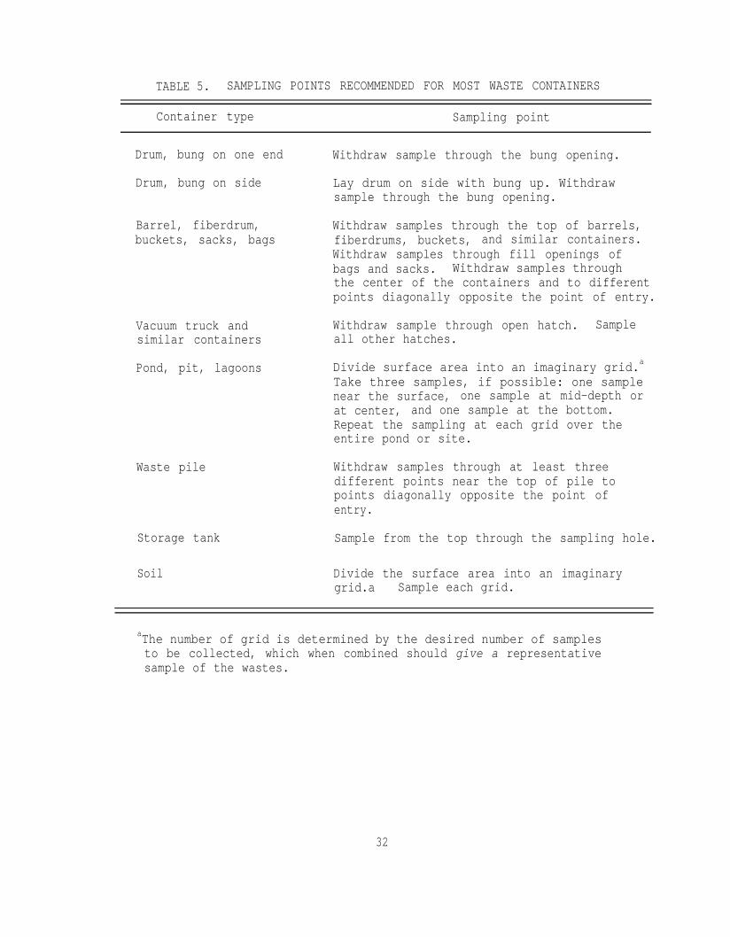
TABLE 5. SAMPLING POINTS RECOMMENDED FOR MOST WASTE CONTAINERS
Container type Sampling point
Drum, bung on one end Withdraw sample through the bung opening.
Drum, bung on side Lay drum on side with bung up. Withdrawsample through the bung opening.
Barrel, fiberdrum,buckets, sacks, bags
Withdraw samples through the top of barrels,fiberdrums, buckets, and similar containers.Withdraw samples through fill openings ofbags and sacks. Withdraw samples throughthe center of the containers and to differentpoints diagonally opposite the point of entry.
Vacuum truck andsimilar containers
Pond, pit, lagoons
Withdraw sample through open hatch. Sampleall other hatches.
Divide surface area into an imaginary grid.aTake three samples, if possible: one samplenear the surface, one sample at mid-depth orat center, and one sample at the bottom.Repeat the sampling at each grid over theentire pond or site.
Waste pile Withdraw samples through at least threedifferent points near the top of pile topoints diagonally opposite the point ofentry.
Storage tank Sample from the top through the sampling hole.
Soil Divide the surface area into an imaginarygrid.a Sample each grid.
aThe number of grid is determined by the desired number of samplesto be collected, which when combined should give a representativesample of the wastes.
32
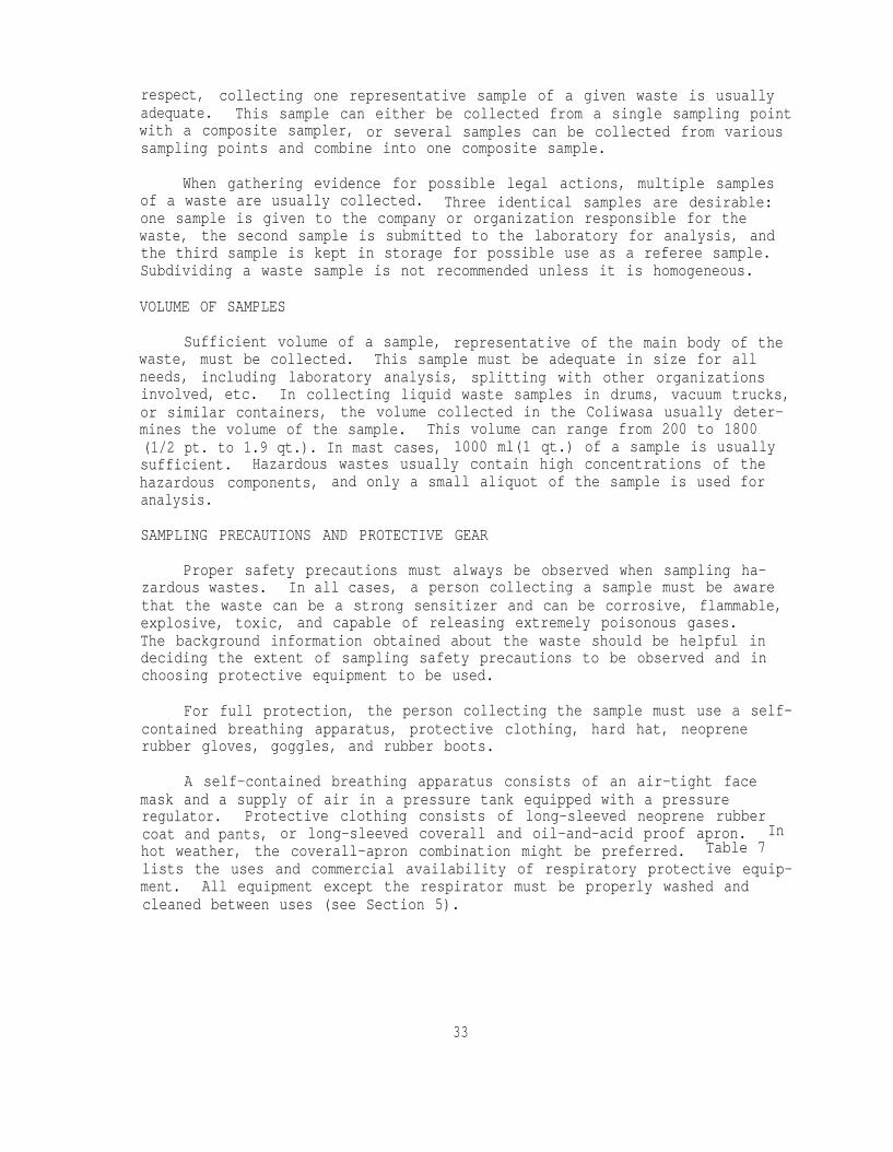
respect, collecting one representative sample of a given waste is usuallyadequate. This sample can either be collected from a single sampling pointwith a composite sampler, or several samples can be collected from varioussampling points and combine into one composite sample.
When gathering evidence for possible legal actions, multiple samplesof a waste are usually collected. Three identical samples are desirable:one sample is given to the company or organization responsible for thewaste, the second sample is submitted to the laboratory for analysis, andthe third sample is kept in storage for possible use as a referee sample.Subdividing a waste sample is not recommended unless it is homogeneous.
VOLUME OF SAMPLES
Sufficient volume of a sample, representative of the main body of thewaste, must be collected. This sample must be adequate in size for allneeds, including laboratory analysis, splitting with other organizationsinvolved, etc. In collecting liquid waste samples in drums, vacuum trucks,or similar containers, the volume collected in the Coliwasa usually deter-mines the volume of the sample. This volume can range from 200 to 1800(1/2 pt. to 1.9 qt.). In mast cases, 1000 ml(1 qt.) of a sample is usuallysufficient. Hazardous wastes usually contain high concentrations of thehazardous components, and only a small aliquot of the sample is used foranalysis.
SAMPLING PRECAUTIONS AND PROTECTIVE GEAR
Proper safety precautions must always be observed when sampling ha-zardous wastes. In all cases, a person collecting a sample must be awarethat the waste can be a strong sensitizer and can be corrosive, flammable,explosive, toxic, and capable of releasing extremely poisonous gases.The background information obtained about the waste should be helpful indeciding the extent of sampling safety precautions to be observed and inchoosing protective equipment to be used.
For full protection, the person collecting the sample must use a self-contained breathing apparatus, protective clothing, hard hat, neoprenerubber gloves, goggles, and rubber boots.
A self-contained breathing apparatus consists of an air-tight facemask and a supply of air in a pressure tank equipped with a pressureregulator. Protective clothing consists of long-sleeved neoprene rubbercoat and pants, or long-sleeved coverall and oil-and-acid proof apron. Inhot weather, the coverall-apron combination might be preferred. Table 7lists the uses and commercial availability of respiratory protective equip-ment. All equipment except the respirator must be properly washed andcleaned between uses (see Section 5).
33
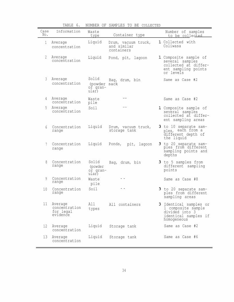
TABLE 6. NUMBER OF SAMPLES TO BE COLLECTEDCaseNo.
Information Wastetype Container type
Number of samplesto be collected
1
2
3
4
5
6
7
8
9
10
11
12
13
Averageconcentration
Averageconcentration
Averageconcentration
AverageconcentrationAverageconcentration
Concentrationrange
Concentrationrange
Concentrationrange
Concentrationrange
Concentrationrange
Averageconcentrationfor legalevidence
AverageconcentrationAverageconcentration
Liquid Drum, vacuum truck,and similarcontainers
Liquid Pond, pit, lagoon
Solid Bag, drum, bin(powder sackor gran-ular)
WastepileSoil
--
--
Liquid Drum, vacuum truck,storage tank
Liquid Ponds, pit, lagoon
Solid Bag, drum, bin(powderor gran-ular)WastepileSoil
- -
- -
Same as Case #8
to 20 separate sam-ples from differentsampling areas
Alltypes
All containers
Liquid Storage tank
Identical samples or1 composite sampledivided into 3identical samples ifhomogeneousSame as Case #2
Liquid Storage tank Same as Case #6
Collected withColiwasa
Composite sample ofseveral samplescollected at differ-ent sampling pointsor levelsSame as Case #2
Same as Case #2
Composite sample ofseveral samplescollected at differ-ent sampling areasto 10 separate sam-ples, each from adifferent depth ofthe liquidto 20 separate sam-ples from differentsampling points anddepthsto 5 samples fromdifferent samplingpoints
34

TABLE 7. RESPIRATORY PROTECTIVE DEVICES RECOMMENDED
FOR VARIOUS HAZARDS
Type of hazard Recommended respiratory device
Oxygen deficiency Self-contained breathing apparatus,hose mask with blower
Gaseous contaminantimmediately dangerousto life
Self-contained breathing apparatus,hose mask with blower,gas mask
Gaseous contaminantnot immediatelydangerous to life
Air-line respirator,hose mask without blower,chemical-cartridge respirator
Particulate contaminant Dust, mist, or fume respirator,air-line respirator,abrasive-blasting respirator
Combination of gaseous andparticulate contaminantsimmediately dangerous tolife
Self-contained breathing apparatus,hose mask with blower,gas mask with special filter
Combination of gaseousand particulate contaminantsnot immediatelydangerous to life
Air-line respirator,hose mask without blower,chemical-cartridge respiratorwith special filter
aSource: Reference 14.
35

The self-contained breathing apparatus may not be required in allsampling situations. In some cases, gas masks or chemical cartridge-typerespirators with filters will suffice. Table 7 may be used to select theproper protective respiratory device.
For added protection in sampling, a second person with a radio-telephone and first-aid kit must be present to render any necessaryhelp or call for assistance.
SAMPLING PROCEDURES
The following procedures are recommended for sampling different typesof hazardous wastes in various containers.
Sampling a Drum
Drums containing liquid wastes can be under pressure or vacuum. Abulging drum usually indicates that it is under high pressure and shouldnot be sampled until the pressure can be safely relieved. A heavilycorroded or rusted drum can readily rupture and spill its contents whendisturbed; it should only be sampled with extreme caution. Opening thebung of a drum can produce a spark that might detonate an explosive gasmixture in the drum. This situation is difficult to predict and must betaken into consideration every time a drum is opened. The need for fullprotective sampling equipment cannot be overemphasized when sampling adrum.
1. Position the drum so that the bung is up (drums with the bung on theend should be positioned upright; drums with bungs on the side shouldbe laid on its side, with the bungs up).
2. Allow the contents of the drum to settle.
3. Slowly loosen the bung with a bung wrench, allowing any gas pressureto release.
4. Remove the bung and collect a sample through the bung hole with aColiwasa, as directed in Section 4.
5. When there is more than one drum of waste at a site, segregate andsample the drums according to waste types, using a table of randomnumbers as outlined in Appendix D.
Sampling a Vacuum Truck
Sampling a vacuum truck requires the person collecting the sample toclimb onto the truck and walk along a narrow catwalk. In some trucks, itrequires climbing access rungs to the tank hatch. These situations pre-sent accessability problems to the sample collector, who most usually
36

wear full protective sampling gear. Preferably, two persons shouldperform the sampling: One person should do the actual sampling and theother should hand the sampling device, stand ready with the sample con-tainer, and help deal with any problems. The sample collector shouldposition himself to collect samples only after the truck driver hasopened the tank hatch. The tank is usually under pressure or vacuum.The driver should open the hatch slowly to release pressure or to breakthe vacuum.
1. Let the truck driver open the tank hatch.
2. Using protective sampling gear, assume a stable stance on the tankcatwalk or access rung to the hatch.
3. Collect a sample through the hatch opening with a Coliwasa, asdirected in Section 4.
4. If the tank truck is not horizontal, take one additional sample eachfrom the rear and front clean out hatches and combine all threesamples in one sample container.
5. When necessary, carefully take sediment sample from the tank throughthe drain spigot.
Sampling a Barrel, Fiberdrum, Can, Bags, or Sacks Containing Powderor Granular Waste
The proper protective respirator (see Table 7), in addition to theother protective gear, must be worn when sampling dry powdered or granu-lar wastes in these containers. These wastes tend to generate airborneparticles when the containers are disturbed. The containers must beopened slowly. The barrels, fiberdrums, and cans must be positionedupright. If possible, sample sacks or bags in the position you findthem, since standing them upright might rupture the bags or sacks.
1. Collect a composite sample from the container with a grain sampleror sampler trier, as directed in Section 4.
2. When there is more than one container of waste at a site, segregateand sample the containers according to a table of random numbers, asoutlined in Appendix D.
Sampling a Pond
Storage or evaporation ponds for hazardous wastes vary greatly insize from a few to a hundred meters. It is difficult to collect repre-sentative samples from the large ponds without incurring huge expenseand assuming excessive risks. Any samples desired beyond 3.5m(ll 1/2 ft)from the bank may require the use of a boat, which is very risky, orthe use of a crane or a helicopter, which is very expensive. The
37

information sought must be weighed against the risk and expense of col-lecting the samples. The pond sampler described in Section 4 can be usedto collect samples as far as 3.5 m(ll 1/2 ft ) from the bank.
1. Collect a composite sample with pond sampler, as directed in Section4.
Sampling Soil
The techniques of soil sampling are numerous.lined below are adopted from ASTM methods.15
The procedures out-The procedures are consist-
ent with the hazardous waste management objective of collecting soilsamples which is usually to determine the amount of hazardous materialdeposited on a particular area of land or to determine the leaching rateof the material and/or determine the residue level on the soil. Elaboratestatistically designed patterns have been designed for sampling soils. Ifone of these patterns is to be used, a good statistics book may have to beconsulted. In the following procedures, soil samples are taken in a gridpattern over the entire site to ensure a uniform coverage.
1. Divide the area into an imaginary grid (see Table 5).
2. Sample each grid and combine the samples into one.
3. To sample up to 8 cm(3 in.) deep, collect samples with a scoop, asdirected in Section 4.
4. To sample beyond 8 cm(3 in.) deep, collect samples with a soil augeror Veihmeyer soil sampler, as directed in Section 4.
Sampling a Waste Pile
Waste piles can range from small heaps to a large aggregates ofwastes. The wastes are predominantly solid and can be a mixture of powders,granules, and chunks as large as or greater than 2.54 cm(1 in.) averagediameter. A number of core samples have to be taken at different anglesand cornposited to obtain a sample that, on analysis, will give averagevalues for the hazardous components in the waste pile.
1. Determine the sampling points (see Table 5).
2. Collect a composite sample with a waste pile sampler according to thedirections in Section 4.
Sampling a Storage Tank
The collection of liquid samples in storage tanks is extremely dis-cussed in the ASTM methods.of those methods.16
The procedure used here is adopted from one
38
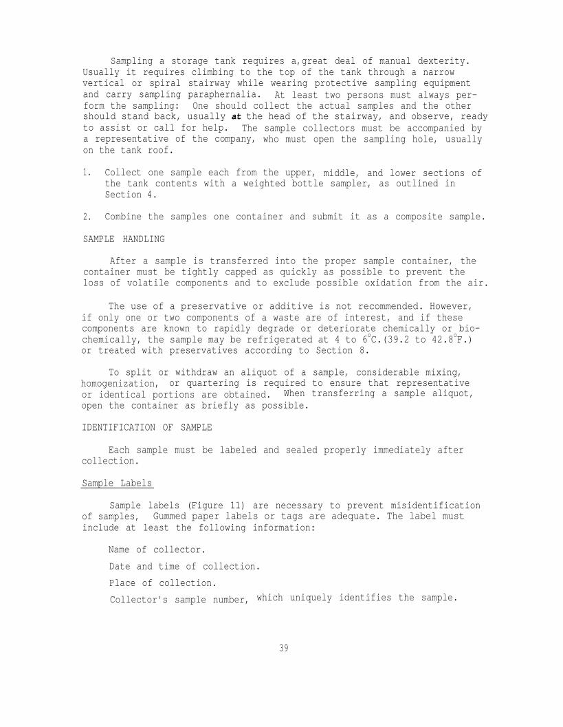
Sampling a storage tank requires a,great deal of manual dexterity.Usually it requires climbing to the top of the tank through a narrowvertical or spiral stairway while wearing protective sampling equipmentand carry sampling paraphernalia. At least two persons must always per-form the sampling: One should collect the actual samples and the othershould stand back, usually at the head of the stairway, and observe, readyto assist or call for help. The sample collectors must be accompanied bya representative of the company, who must open the sampling hole, usuallyon the tank roof.
1. Collect one sample each from the upper, middle, and lower sections ofthe tank contents with a weighted bottle sampler, as outlined inSection 4.
2. Combine the samples one container and submit it as a composite sample.
SAMPLE HANDLING
After a sample is transferred into the proper sample container, thecontainer must be tightly capped as quickly as possible to prevent theloss of volatile components and to exclude possible oxidation from the air.
The use of a preservative or additive is not recommended. However,if only one or two components of a waste are of interest, and if thesecomponents are known to rapidly degrade or deteriorate chemically or bio-chemically, the sample may be refrigerated at 4 to 6oC.(39.2 to 42.8oF.)or treated with preservatives according to Section 8.
To split or withdraw an aliquot of a sample, considerable mixing,homogenization, or quartering is required to ensure that representativeor identical portions are obtained. When transferring a sample aliquot,open the container as briefly as possible.
IDENTIFICATION OF SAMPLE
Each sample must be labeled and sealed properly immediately aftercollection.
Sample Labels
Sample labels (Figure 11) are necessary to prevent misidentificationof samples, Gummed paper labels or tags are adequate. The label mustinclude at least the following information:
Name of collector.Date and time of collection.Place of collection.Collector's sample number, which uniquely identifies the sample.
39

OFFICIAL SAMPLE LABELCollector
Place of Collection
Collector's Sample No.
Date Sampled
Field Information
Time Sampled
Figure 11. Example of official sample label.
OFFICIAL SAMPLE SEALState of California Public Health Division
Department of Health Services. Hazardous Materials Laboratory
Collected by Collector's Sample No.(signature)
Date Collected Time CollectedPlace Collected
Figure 12. Example of official sample seal
40
Sample Seals
Sample seals are used to preserve the integrity of the sample from thetime it is collected until it is opened in the laboratory. Gummed paperseals can be used as official sample seals. The paper seal must carryinformation such as:
Collector's name
Date and time of sampling
Collector's sample number. (This number must be identical with thenumber on the sample label).
The seal must be attached in such a way that it is necessary to breakit in order to open the sample container. An example of a sample seal isshown in Figure 12.
FIELD LOG BOOK
All information pertinent to a field survey and/or sampling must berecorded in a log book. This must be a bound book, preferabley with con-secutively numbered pages that are 21.6 by 27.9 cm(8 1/2 by 11 in.). Entriesin the log book must include at least the following:
Purpose of sampling (e.g., surveillance, etc.)
Location of sampling (e.g., hauler, disposal site, etc.) and address
Name and address of field contact
Producer of waste and address
Type of process (if known) producing waste
Type of waste (e.g., sludge, wastewater, etc.)
Declared waste components and concentrations
Number and volume of sample taken
Description of sampling point
Date and time of collection
Collector's sample identification number(s)
Sample distribution (e.g., laboratory, hauler, etc.)References such as maps or photographs of the sampling Site
Field observations
Any field measurements made such as pH, flammability, explositivity,etc.
Sampling situations vary widely. No general rule can be given as tothe extent of information that must be entered in the log book. A good
41
rule, however, is to record sufficient information so that someone canreconstruct the sampling situation without reliance on the collector'smemory.
The log book must be protected and kept in a safe place.
CHAIN OF CUSTODY RECORD
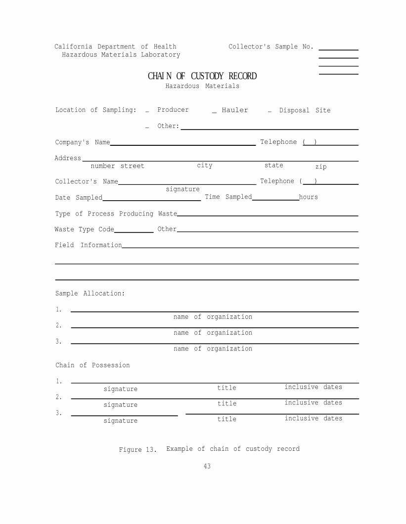
To establish the documentation necessary to trace sample possessionfrom the time of collection, a chain of custody record must be filled outand accompany every sample. This record becomes especially important whenthe sample is to be introduced as evidence in a court litigation. Anexample of a chain of custody record is illustrated in Figure 13.
The record must contain the following minimum information:Collector's sample numberSignature of collectorDate and time of collectionPlace and address of collectionWaste typeSignatures of persons involved in the chain of possessionInclusive dates of possession
SAMPLE ANALYSIS REQUEST SHEET
The sample analysis request sheet (Figure 14) is intended to accom-pany the sample on delivery to the laboratory. The field portion of thisform must be completed by the person collecting the sample and shouldinclude most of the pertinent information noted in the log book. Thelaboratory portion of this form is intended to be completed by laboratorypersonnel and to include:
Name of person receiving the sampleLaboratory sample numberDate of sample receiptSample allocationAnalyses to be performed
SAMPLE DELIVERY TO THE LABORATORY
Preferably, the sample must be delivered in person to the laboratoryfor analysis as soon as practicable --usually the same day as the sampling.Consult Section 8 when sample preservation is required. The sample must
42
California Department of HealthHazardous Materials Laboratory
Collector's Sample No.
CHAIN OF CUSTODY RECORDHazardous Materials
Location of Sampling: Producer- _ Hauler - Disposal Site
Other:-
Company's Name Telephone ( )
Addressnumber street city state zip
Collector's Name
Date Sampled
Telephone ( )signature
Time Sampled hours
Type of Process Producing Waste
Waste Type Code Other
Field Information
Sample Allocation:
1.
2.
3.
name of organization
name of organization
name of organization
Chain of Possession
1.signature title inclusive dates
2.signature title inclusive dates
3.signature title inclusive dates
Figure 13. Example of chain of custody record
43

PRIORITY(explain)
California Department of Health ServicesHazardous Materials Laboratory
HAZARDOUS MATERIALS SAMPLE ANALYSIS REQUESTPART I: FIELD SECTION
Collector Date Sampled Time hours
Location of Samplingname of company, disposal site, etc.
Addressnumber street c i t y state zip
Telephone ( ) Company Contact
HML NO. COLLECTOR'S TYPE OF(Lab only) SAMPLE NO. SAMPLE* FIELD INFORMATION*
Analysis Requested
Special Handling and/or Storage
PART II: LABORATORY SECTION
Received by Title DateSample Allocation: HML LBL LABL SRLAnalysis Required
Date- - -
*Indicate whether sample is sludge, soil, etc.; **Use back of page foradditional information.
Figure 14. Example of hazardous waste sample analysis request sheet
44

be accompanied by the chain of custody record and by a sample analysisrequest sheet (Figure 14). The sample must be delivered to the personin the laboratory authorized to receive samples (often referred to asthe sample custodian).
SHIPPING OF SAMPLES
When a sample is shipped to the laboratory, it must be packaged in aproper shipping container to avoid leakage and/or breakage. A cardboardbox that will provide at least 10 cm(4 in.) of tight packing around thesample container must be used. Acceptable packing materials include saw-dust, crumpled newspapers, vermiculite, polyurethane chips, etc. Othersamples that require refrigeration must be packed with reusable plasticpacks or cans of frozen freezing gels in molded polyurethane boxes withsturdy fiberboard protective case. The boxes must be taped closed withmasking tape or fiber plastic tape.
All packages must be accompanied by a sample analysis sheet and chainof custody record. Complete address of the sender and the receiving lab-oratory must legibly appear on each package. When sent by mail, registerthe package with return receipt requested. When sent by common carrier,obtain a copy of the bill of lading. Post office receipts and bill oflading copies may be used as part of the chain of custody documentation.17
45
SECTION 7
RECEIPT AND LOGGING OF SAMPLE
Field samples are delivered to the laboratory either personally orthrough a public carrier. In the laboratory, a sample custodian shouldbe assigned to receive the samples. Upon receipt of a sample, the custo-dian should inspect the condition of the sample and the sample seal,reconcile the information on the sample label and seal against that on thechain of custody record, assign a laboratory number, log in the sample inthe laboratory log book, and store the sample in a secured sample storageroom or cabinet until assigned to an analyst for analysis.
SAMPLE INSPECTION
The sample custodian should inspect the sample for any leakage fromthe container. A leaky container containing multiphase sample shouldnot be accepted for analysis. This sample will no longer be a represen-tative sample. If the sample is contained in a plastic bottle and thewalls show any bulging or collapsing, the custodian should note that thesample is under pressure or releasing gases, respectively. A sampleunder pressure should be treated with caution. It can be explosive orrelease extremely poisonous gases. The custodian should examine whetherthe sample seal is intact or broken, since broken seal may mean sampletampering and would make analysis results inadmissible in court as evi-dence. Discrepancies between the information on the sample label and sealand that on the chain of custody record and the sample analysis requestsheet should be resolved before the sample is assigned for analysis. Thiseffort might require communication with the sample collector. Results ofthe inspection should be noted on the sample analysis request sheet andon the laboratory sample log book.
ASSIGNMENT OF LABORATORY NUMBER
Incoming samples usually carry the inspector's or collector's identi-fication numbers. To further identify these samples, the laboratoryshould assign its own identification numbers, which normally are givenconsecutively. Each sample should be marked with the assigned laboratorynumber. This number is correspondingly recorded on a laboratory samplelog book along with the information describing the sample. The sampleinformation is copied from the sample analysis request sheet and cross-checked against that on the sample label.
46

ASSIGNMENT OF SAMPLE FOR ANALYSIS
In most cases, the laboratory supervisor assigns the sample for ana-lysis. The supervisor should review the information on the sample analysisrequest sheet, which now includes inspection notes recorded by the labora-tory sample custodian. The supervisor should then decide what analysesare to be performed. The sample may have to be split with other labora-tories to obtain the necessary information about the sample. The super-visor should decide on the sample allocation and delineate the types ofanalyses to be performed on each allocation. In his own laboratory, thesupervisor should assign the sample analysis to at least one chemist, whois to be responsible for the care and custody of the sample once it ishanded to him. He should be prepared to testify that the sample was inhis possession or secured in the laboratory at all times from the momentit was received from the custodian until the analyses were performed.
The receiving chemist should record in his laboratory notebook theidentifying information about the sample, the date of receipt, and otherpertinent information. This record should also include the subsequentanalytical data and calculations.
47

SECTION 8
PRESERVATION AND STORAGE OF SAMPLES
Ideally, hazardous waste samples should be analyzed immediately aftercollection for maximum reliability of the analytical results. Hazardouswastes are such complex mixtures that it is difficult to exactly predictthe physical, biological, and chemical changes that occur in the sampleswith time. After collection of samples, pH may change significantly in amatter of minutes; sulfides and cyanides may be oxidized or evolve asgases; and hexavalent chromium may slowly be reduced to the trivalentstate. Certain cations may be partly lost as a result of adsorption tothe walls of the sample containers. Growth of microorganisms may alsocause changes to certain constituents of the sample. Volatile compoundsmay be rapidly lost.
In a number of cases, the above changes may be slowed down or pre-vented by refrigeration at 4 to 6OC, or by the addition of preservatives.However, these treatments mostly apply to one or two components or pro-perties. Refrigeration may deter the evolution of volatile components andacid gases such as hydrogen sulfides and hydrogen cyanides, but it alsointroduces the uncertainty that some salts may precipitate at lower temper-ature. On warming to room temperature for analysis, the precipitates maynot redissolve, thus incurring error in determining the actual concentra-tions of dissolved sample constituents. Addition or preservatives mayretard biochemical changes, whereas other additives may convert someconstituents to stable hydroxides, salts, or compounds. Unknown in thesetreatments, however, is the possible conversion of other compounds to otherforms (such as the products of nitration, sulfonation, oxidation, etc., oforganic components). In subsequent analyses, the results may not reflectthe original identity of the components.
Thus, both advantages and disadvantages are associated with the refri-geration and/or addition of preservatives or additives to waste samples.These methods of preservation or stabilization are not recommended forhazardous waste samples unless only one or two components or propertiesare to be analyzed.
Standard methods books 18, l9 have compilations of useful preservativesfor various constitutents. Table 8 is excerpted from these lists and showsonly the preservation methods that may be used for hazardous wastes.
48
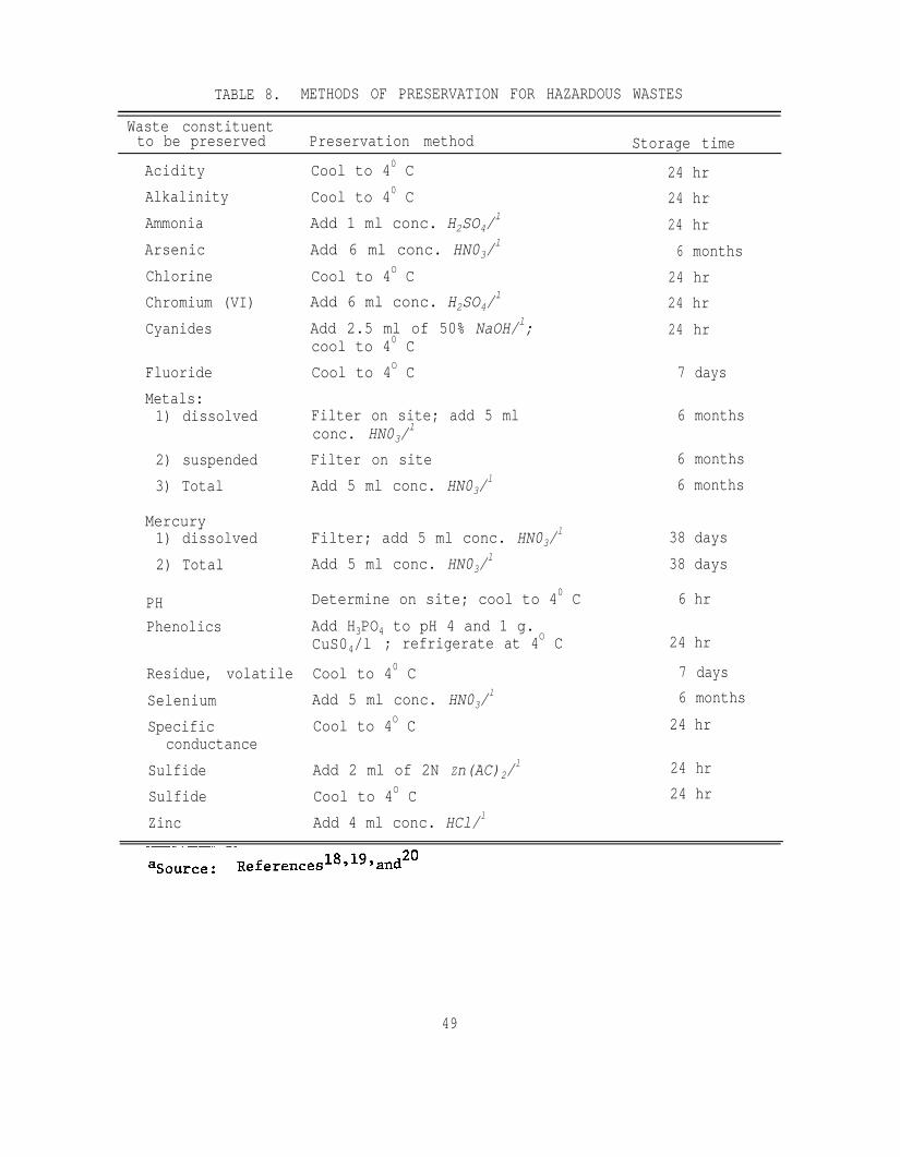
TABLE 8. METHODS OF PRESERVATION FOR HAZARDOUS WASTES
Waste constituentto be preserved Preservation method Storage timeAcidityAlkalinityAmmoniaArsenicChlorineChromium (VI)Cyanides
FluorideMetals:1) dissolved
2) suspended3) Total
Mercury1) dissolved2) Total
PHPhenolics
Residue, volatileSeleniumSpecific
conductanceSulfideSulfideZinc
Cool to 40 CCool to 40 CAdd 1 ml conc. H2SO4/
l
Add 6 ml conc. HN03/l
Cool to 4O CAdd 6 ml conc. H2SO4/
l
Add 2.5 ml of 50% NaOH/l;cool to 40 CCool to 4O C
Filter on site; add 5 mlconc. HN03/
l
Filter on siteAdd 5 ml conc. HN03/
l
Filter; add 5 ml conc. HN03/l
Add 5 ml conc. HN03/l
Determine on site; cool to 40 CAdd H3PO4 to pH 4 and 1 g.CuS04/l ; refrigerate at 4O C
Cool to 40 CAdd 5 ml conc. HN03/
l
Cool to 4O C
Add 2 ml of 2N Zn(AC)2/l
Cool to 4O CAdd 4 ml conc. HCl/l
24 hr24 hr24 hr6 months
24 hr24 hr24 hr
7 days
6 months
6 months6 months
38 days38 days
6 hr
24 hr
7 days6 months
24 hr
24 hr24 hr
49

REFERENCES
1. Stephens, R. D. 1976. Hazardous Sampling; Residual Management by LandDisposal. Proceedings of the Hazardous Waste Research Symposium,University of Arizona, Tucson, Ariz.
2. Eichenberger, B., J. R. Edwards, K. Y. Chen, and R. D. Stephens. 1977.A Case Study of Hazardous Wastes Input Into Class I Landfills. U.S.Environmental Protection Agency, Cincinnati, Ohio.
3. Merck Index, An Encyclopedia of Chemicals and Drugs. 1968. 9th Ed.Merck & Co., Rahway.
4. Chemical Resistance of Excelon R-4000. 1977. Thermoplastic Process,Inc., Stirling, N.J.
5. Sampling Procedure for Animal Feed. Official Methods of Analysis ofthe Association of Official Analytical Chemists. 1975. 12th Ed.Washington, D.C., p. 129.
6. Guidelines on Sampling and Statistical Methodologies for Ambient Pesti-cide Monitoring. 1974. Federal Working Group on Pest Management, U.S.Environmental Protection Agency, Washington, D.C., p. III-5.
7. Veihmeyer, F. J. 1929. An Improved Soil-Sampling Tube. Soil Science27(2): 147-152.-
8. American Society for Testing and Materials. 1975. ASTM D270. ASTMStandards. The Society, Philadelphia, Pa.
9. American Society for Testing and Materials. 1973. ASTM E 300. ASTMStandards. The Society, Philadelphia, Pa.
10. Sax, I. N. 1968. Dangerous Properties of Industrial Materials. 3rdEd. Van Nostrand Reinhold Co. New York, N.Y.
11. Condensed Chemical Dictionary. 1977. 8th Ed. Van Nostrand Reinholdco., New York, N.Y.
12. Toxic and Hazardous Industrial Chemicals Safety Manual for Handlingand Disposal With Toxicity and Hazardous Data. 1976. InternationalTechnical Information Institute, Tokyo, Japan.
13. Dunlap, J. 1972. Industrial Waste Law (AB 5961, State of California.
50
14.
15.
16.
17.
18.
19.
20.
Bureau of Labor Standards. Respiratory Protective Equipment.Bulletin 226. Safety in Industry; Environmental and ChemicalHazards, No. 3. U.S. Department of Labor, Washington, D.C.
American Society for Testing and Materials. ASTM D1452, D1586 andD3550. ASTM Standards. The Society, Philadelphia, Pa.
American Society for Testing and Materials. ASTM D270 and E 300ASTM Standards. The Society, Philadelphia, Pa.
Compliance Monitoring Procedures. 1974. EPA 330/l-74-/002. U.S.Environmental Protection Agency, Denver, Colo.
Manual of Methods for Chemical Analysis of Water and Wastewater.1974. EPA-62516-74-003. U.S. Environmental Protection Agency,Washington, D.C.
Standard Methods for Examination of Water and Wastewater. 1975. 14thEd. American Public Health Association, New York, N.Y.
Collection, Storage, Transportation, and Pretreatment of Water andWastewater Samples. 1971. California Department of Health Services,Berkeley, Ca.
51
APPENDICES
APPENDIX A. DEVELOPMENT 0F THE COMPOSITE LIQUID WASTE SAMPLER (COLIWASA)
Early in the development of the California waste management program,the needs were recognized for accurate information about waste compositionand adequate equipment and procedures for sampling and analysis.
In 1975, the California Department of Health Services engaged in acooperative study with the University of Southern California (EnvironmentalEngineering Department) under U.S. Environmental Protection Agency's spon-sorship to collect and analyze a large number of hazardous waste samplesat a number of Class I disposal sites in Los Angeles County. In the prep-aration of this study, the Department of Health Services personnel designedand constructed a simple tube sampler suitable for use in liquid and sludgewastes. The objective of the sampler design was to obtain samples represent-ative of complex, heterogeneous wastes contained in vacuum trucks and drums.In preliminary testing, the prototype design shown in Figure A-l appeared togive good representative samples. At this time, the sampling device wasnamed the composite liquid waste sampler, or Coliwasa for short.
Requirements for Hazardous Waste Sampling Procedures and Equipment
Approximately 24 of these devices were constructed for use in the LosAngeles County sampling program. During a 2-week period in 1975, 400 samplesof hazardous wastes were taken from vacuum trucks and drums. The wastesrepresented an extremely wide variety of chemical compositions and physicalcharacteristics. The experience given by this sampling program emphasizedthe following important requirements of hazardous waste sampling proceduresand equipment:
1) Sampling equipment must be of simple design to facilitate easy cleaningor to allow discard if necessary to prevent sample cross contamination.Many wastes, because of their chemical composition and/or physical nature,so fouled sampling equipment that it required discarding or extensivecleaning. Extensive cleaning produces a significant volume of cleaningwaste that must be properly disposed. Equipment that has complicatedvalves, levers, and other fittings would never survive many hazardouswastes.
2) Equipment must be light weight and leak proof. Sampling personnel arerequired to climb and move about on tank trucks and other dangerous areaswhile holding sampling equipment. Once the sampler is filled with its
52
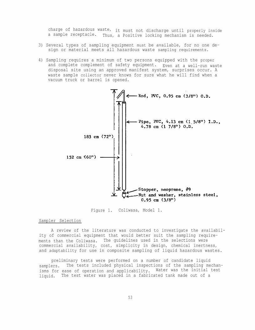
charge of hazardous waste,a sample receptacle.
it must not discharge until properly insideThus, a Positive locking mechanism is needed.
3) Several types of sampling equipment must be available, for no one de-sign or material meets all hazardous waste sampling requirements.
4) Sampling requires a minimum of two persons equipped with the properand complete complement of safety equipment. Even at a well-run wastedisposal site using an approved manifest system, surprises occur. Awaste sample collector never knows for sure what he will find when avacuum truck or barrel is opened.
Figure 1. Coliwasa, Model 1.
Sampler Selection
A review of the literature was conducted to investigate the availabil-ity of commercial equipment that would better suit the sampling require-ments than the Coliwasa. The guidelines used in the selections werecommercial availability, cost, simplicity in design, chemical inertness,and adaptability for use in composite sampling of liquid hazardous wastes.
preliminary tests were performed on a number of candidate liquidsamplers. The tests included physical inspections of the sampling mechan-isms for ease of operation and applicability. Water was the initial testliquid. The test water was placed in a fabricated tank made out of a
53

122-cm(4-ft) tall by 15.2-cm(6-in.) I.D. glass cylinder. Each samplerunder test was lowered slowly into the tank to determine whether the checkvalve or closing device or sampling orifice would allow the sample to flowin the sampler. The sampler was then withdrawn and tested for leakage andease of transfer of the collected sample.
None of the commercially available samplers was found to be satis-factory. The Coliwasa designed by the Department of Health Servicesappeared to be the most promising.
First Coliwasa Model
The early design of the Coliwasa (Model 1; Figure A-l) consisted of1.52-m(5-ft.) by 4.13-cm(l5/8-in.) I.D., opaque PVC pipe as the samplingtube and a neoprene stopper attached to one end of a 0.95-cm(3/8-in.) O.D.PVC rod as the closing mechanism. To collect a sample with this sampler,the stopper is pushed out about 5 cm(2 in.) from the bottom end of thesampling tube. Then the sampler is lowered straight down through the bodyof liquid waste to be sampled to the bottom of the waste container. Theliquid in the tube is trapped by plugging the bottom of the tube with thestopper by pulling up the stopper rod with one hand and holding the tubewith the other hand.
This early design of the Coliwasa, albeit functional, was deficient ina number of aspects. First, it was difficult to put the sampler in theclose position. The stopper did not easily line up with the bottom openingof the sampling tube. Several manipulations of the stopper rod were usuallyrequired to effect closure. This difficulty tended to disturb the bottomlayer of the waste being sampled and undoubtedly contributed to the col-lection of nonrepresentative samples.
Second, the sampler was not equipped with a mechanism that positivelyand independently locked it closed. Closure was maintained by using onehand to hold the sampling tube and the other hand to maintain a constantupward pressure on the upper end of the stopper rod to keep the stoppertightly seated against the bottom opening of the sampler. In some samp-ling instances, this method of closure was not always practical. Whensampling waste containers as deep as the length of the sampler, the opera-tor could not withdraw the sampler without freeing the hand that maintainsthe closing pressure on the stopper rod. Thus, the snug contact betweenthe neoprene stopper and the inner opening of the sampling tube was theonly force that locked the sampler closed. The weight of the sample con-tained in the sampling tube has in some cases pushed out the stopper,resulting in lost samples and exposure of the sample collector to unneces-sary hazards.
Third, samples contained in the sampler were difficult to transferinto sample containers at regulated rates, and caused some samples to belost from splashings.
54

Attempts were made to improve the first model of the Coliwasa. Theseefforts led to fabrication of the other models shown in Figures A-2 throughA-5, and finally to the recommended version as shown in Figure 1 of the text.
Models 2 and 3
The improvement in the second model of the Coliwasa (Figure A-2) con-sisted of making diametrical slits, 5 cm(2 in.) deep by 2 cm(0.79 in.) wide,and indentations 900 from the slits at the top of the sampler tube. Theslits accommodate the T-handle of the stopper rod in the open position, whichallows the stopper to extend down about 5 cm(2 in.) below the bottom of thesampler. The indentations serve as support for the T-handle when the sam-pler is placed in the close position. When this improved Coliwasa was testedthe neoprene stopper still did not readily line up with the bottom openingof the sampling tube. Several twisting manipulations of the stopper rodwere required to bring the sampler into the close position. This problemwas remedied by installing three stainless steel guide wires (18 gauge) onthe stopper, with the upper wire ends secured to the stopper rod, as shownin Figure A-3. This version (Model 3) of the sampler was again tested. Thesampler was found functional and relatively easy to operate. It can be dis-assembled and reassembled for cleaning in about 2 minutes. It can be builtfor less than $10.00. The closing tension on the stopper of this Sampler,however, is not easily adjusted while sampling. This drawback might incursome sample loss.
OPEN
Figure A-2. Coliwasa, Model 2.
55


Model 4
Further investigation into improving the design of the Coliwasa re-sulted in Model 4(Figure A-4). In this version, the locking mechanism ofthe sampler consisted of a threaded PVC plug that rides on a short threaded0.95-cm(3/8-in.) O.D. metal rod. The metal rod is coupled with the PVCstopper rod. To sample, the plug is screwed out about 5 cm and then thestopper rod is pushed downward to open the sampler. The sampler is loweredslowly into the liquid. Upon reaching the bottom of the container, thestopper rod is pulled up to close the sampler. The PVC plug is screwed inuntil tight to secure the stopper in the close position. This design ofthe Coliwasa is simple, functional, and provides the person collecting thesample with control over the tightness of the stopper against the bottomof the sampler. It is, likewise, easily disassembled and reassembled forcleaning. This sampler, however, is slow to operate, the PVC plug does notscrew in and out fast enough. This drawback tends to expose the sample col-lector to the liquid waste during sampling longer than is perhaps necessary.
Another model of the Coliwasa was fabricated using a closing principlesimilar to a float valve (Figure A-5). This sampler was fabricated from a1.52-m(5-ft) by 5.1-cm(2-in.) I.D. plastic pipe. At the bottom end is aplastic reducer fitting (5.1-cm(2-in.) to 3.18-cm(1.5-in.) I.D.). A manu-ally operated neoprene rubber plug attached to a rod is used as the closingdevice. When sampling, the rubber plug is raised about 5 cm(2-in.) aboveits seat, and the sampler is slowly lowered into the liquid.' On reachingthe bottom of the container, the sampler is closed by slowly lowering theplug back to its seat. The sampler is withdrawn and the sample is dischar-ged into a sample container. Tests performed on this sampler showed noleakage of collected samples. This sampler was also found to be the easiestto disassemble and reassemble for cleaning. However, the annular clearancebetween the outside diameter of the stopper and the inside diameter of thesampling tube was too narrow. The sampler tended to stir the liquid mixtureon filling, which could incur the collection of nonrepresentative sample.In addition, the sampler tended to exclude large particles in the wastes.Increasing the tube/stopper annular clearance did not seem practical becauseit conversely reduced the opening of the reducer fitting of the samplingtube.Final Design
A much improved and recommended model of the Coliwasa is shown in Fig-ure 1 of the text. This model features three main improvements over theprevious models. The first improvement consists of the use of a positive,quick engaging closing and locking mechanism. This mechanism consists of ashort-length, channeled aluminum bar that is attached to the sampler'sstopper rod by an adjustable swivel. The aluminum bar serves both as aT-handle and lock for the sampler's closure system. When the sampler is inthe open position, the handle is placed in the T-position and pusheddown agains the locking block. This manipulation pushes out the
57
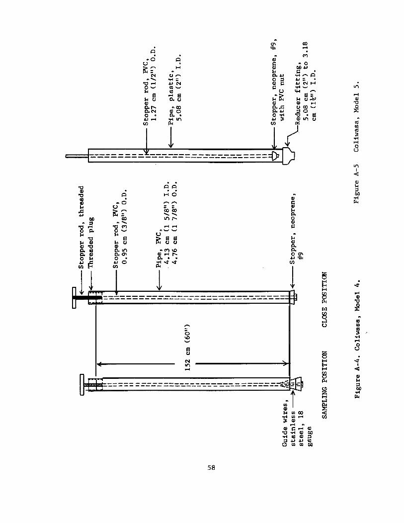

neoprene stopper and opens the sampling tube. In the close position, thehandle is rotated until one leg of the T is squarely perpendicular againstthe locking block. This tightly seats the neoprene stopper against thebottom opening of the sampling tube and positively locks the sampler in theclose position. The closure tension can be adjusted by shortening or length-ening the stopper rod by slightly screwing it in or out of the T handleswivel. In discharging a collected sample, the T handle is slowly broughtinto the T-position. This facilitates the opening of the sampler at a con-trollable rate and permits the transfer of the sample into a sample containerat a regulated rate, thus minimizing splashing or loss of sample.
The second improvement made is the use of a sharply tapered neoprenestopper. The sharp taper of the stopper eliminates the use of guide wiresand facilitates the proper seating of the stopper against the opening of thesampling tube on closure. Thisstopper can be fabricated to specfications byplastic products manufacturers at an extremely high price, or it can be madeby simply grinding down the inexpensive and commercially available neoprenestopper to the desired taper with a shop grinder (Note 1 in Appendix B).
The third improvement is the use of translucent PVC and glass pipesas the sampling tubes. These tubes permit the observation of the phases ofthe liquid waste sample collected in the sampler. The glass sampling tubeis usually used with a Teflon stopper rod. Each tube is used for differentpurposes, as described in Section 4 of the text.
The improved model of the Coliwasa was tested in the field and in thelaboratory and found to be the most practical and capable of collectingrepresentative samples of multiphase liquid wastes samples.
Laboratory Tests
In the laboratory, the testing was conducted using test liquid mixturesin a 122-cm (4-ft) tall by 15.2-cm(6-in.) I.D. glass cylindrical tank. Theglass tank was ideal for the tests because it permitted observation andmeasurement of the relative heights of the liquid phases.
A two-phase liquid mixture consisting of about 13.9 liters of waterand 3.29 liters of waste oil was sampled with the Coliwasa. The samplewas emptied into a l000-ml (1.056 qt) graduated cylinder. The relativevolumes of the liquids were determined and given in Table A-l.
The results indicate that the Coliwasa is capable of obtaining a repre-sentative sample of a two-phase liquid mixture.
59
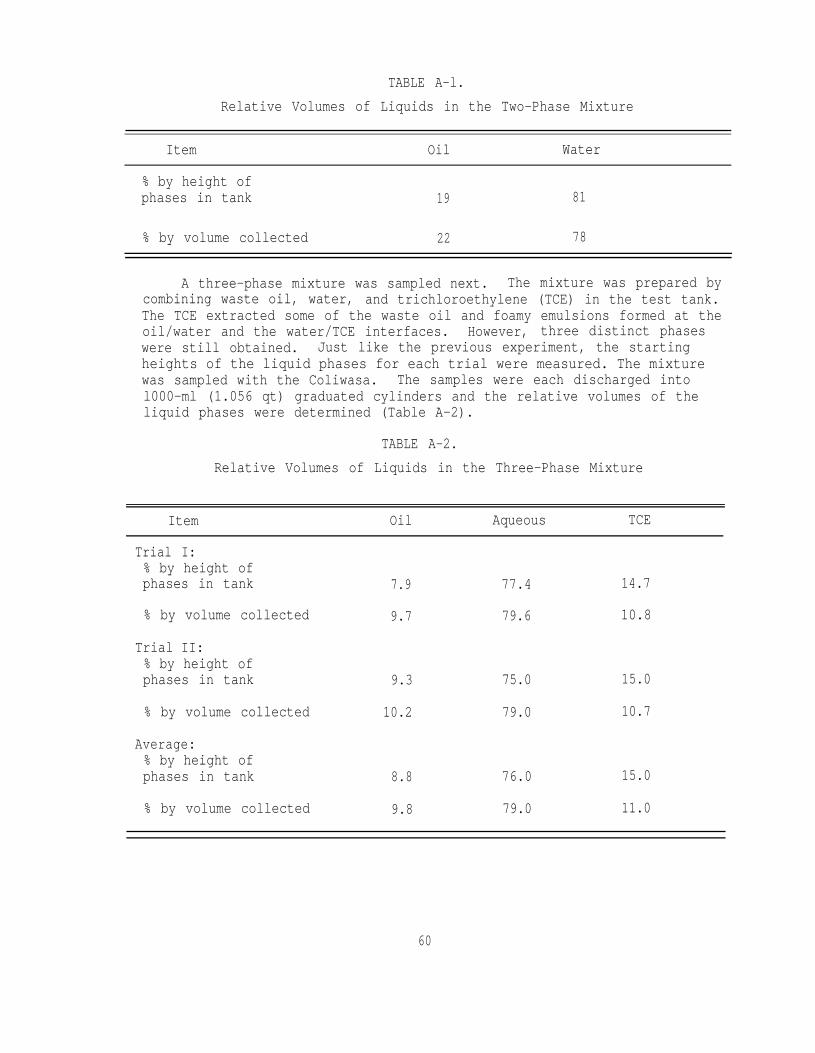
TABLE A-l.Relative Volumes of Liquids in the Two-Phase Mixture
Item Oil Water
% by height ofphases in tank 19 81
% by volume collected 22 78
A three-phase mixture was sampled next. The mixture was prepared bycombining waste oil, water, and trichloroethylene (TCE) in the test tank.The TCE extracted some of the waste oil and foamy emulsions formed at theoil/water and the water/TCE interfaces. However, three distinct phaseswere still obtained. Just like the previous experiment, the startingheights of the liquid phases for each trial were measured. The mixturewas sampled with the Coliwasa. The samples were each discharged intol000-ml (1.056 qt) graduated cylinders and the relative volumes of theliquid phases were determined (Table A-2).
TABLE A-2.Relative Volumes of Liquids in the Three-Phase Mixture
Item Oil Aqueous TCE
Trial I:% by height ofphases in tank 7.9 77.4 14.7
% by volume collected 9.7 79.6 10.8
Trial II:% by height ofphases in tank 9.3 75.0 15.0
% by volume collected 10.2 79.0 10.7
Average:% by height ofphases in tank 8.8 76.0 15.0
% by volume collected 9.8 79.0 11.0
60
The results indicate that the Coliwasa is capable of collecting arepresentative sample of a three-phase mixture within 5% accuracy. Thegreatest nonrepresentative error, as anticipated, occured at the bottomphase because the sampler's rubber stopper prevents sampling of the last2.54 cm(1 in.) to the bottom of the container. This error decreases asthe bottom phase increases in volume as compared to the upper phases.With less viscous and completely immiscible test liquids, the representa-tiveness of the sample collected approaches unity.
Field Tests
The field tests consisted of sampling liquid wastes in drums and invacuum trucks. Drums of unknown liquid wastes are sampled at a hazardouswaste (Class I) disposal site in California. The sampler, which has a4.8-cm (1 7/8in.) O.D., easily cleared through the drum's bung holes.
Sampling was relatively fast. From the time a drum was opened, asample was collected and transferred into a container in less than 5minutes. While a sample was in the sampler, no leakage was detected,indicating a positive seal by the sampler's closing mechanism. On thetransfer of sample to a container, no splashings were observed, showingthat the sampler's content can be discharged at a regulated rate.
A drum containing a two-phase liquid waste mixture was also sampled.Replicate samples were obtained, and each was placed in separate contain-ers. The ratios of the liquid phases in each of the samples were deter-mined and found to be approximately the same, indicating that reproduciblesamples can be collected with the sampler.
Incoming vacuum trucks carrying liquid wastes to the disposal sitewere sampled next with the Coliwasa. Again, the sampler was found to befunctional and very easy to use. Collection of samples was very fast,minimizing the exposure of the sample collector to hazardous fumes andother emissions from the wastes. Only one vacuum truck with a narrow hatchopening and a total depth Of about 163 cm(5.3 ft) was not Successfullysampled. The sampling tube of the Coliwasa is only 152 cm(5 ft) long.A longer sampling tube (i.e., 183 cm(6 ft) long) could have remediedthe problem.
61
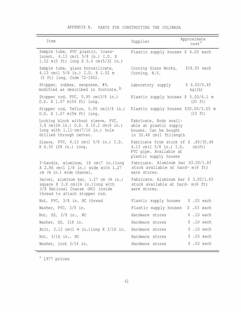
APPENDIX B. PARTS FOR CONSTRUCTING THE COLIWASA
Item Supplier Approximatecosta
T-handle, aluminum, 18 cm(7 in.)longX 2.86 cm(1 l/8 in.) wide with 1.27cm (½ in.) wide channel.Swivel, aluminum bar, 1.27 cm (½ in.)square X 3.8 cm(l½ in.)long with3/8 National Coarse (NC) insidethread to attach stopper rod.Nut, PVC, 3/8 in. NC threadWasher, PVC, 3/8 in.Nut, SS, 3/8 in., NCWasher, SS, 318 in.Bolt, 3.12 cm(1 ¼ in.)long X 3/16 in.Nut, 3/16 in., NCWasher, lock 3/16 in.
Sample tube, PVC plastic, trans-lucent, 4.13 cm(1 5/8 in.) I.D. X1.52 m(5 ft) long X 0.4 cm(5/32 in.)Sample tube, glass borosilicate,4.13 cm(1 5/8 in.) I.D. X 1.52 m(5 ft) long, Code 72-1602.Stopper, rubber, neoprene, #9,modified as described in footnote.b
Stopper rod, PVC, 0.95 cm(3/8 in.)O.D. X 1.67 m(54 ft) long.Stopper rod, Teflon, 0.95 cm(3/8 in.)O.D. X 1.67 m(5½ ft) long.Locking block without sleeve, PVC,3.8 cm(l½ in.) O.D. X 10.2 cm(4 in.)long with l.ll-cm(7/16 in.) holedrilled through center.Sleeve, PVC, 4.13 cm(1 5/8 in.) I.D.X 6.35 (2% in.) long.
Plastic supply houses $ 4.00 each
a 1977 prices
62
Corning Glass Works, $18.00 eachCorning, N.Y.
Laboratory supply $ 6.00/0.45kg(lb)
Plastic supply houses $ 5.00/6.1 m(20 ft)
Plastic supply houses $30.00/3.05 m(10 ft)
Fabricate. Rods avail-able at plastic supplyhouses. Can be boughtin 30.48 cm(1 ft)lengthFabricate from stock of $ .80/30.484.13 cm(1 5/8 in.) I.D. cm(ft)PVC pipe. Available atplastic supply housesFabricate. Aluminum bar S3.00/1.83stock available at hard- m(6 ft)ware stores.Fabricate. Aluminum bar $ 3.00/1.83stock available at hard- m(6 ft)ware stores.
Plastic supply houses $ .03 eachPlastic supply houses $ .03 eachHardware stores $ .lO eachHardware stores $ .lO eachHardware stores $ .lO eachHardware stores $ .03 eachHardware stores $ .03 each
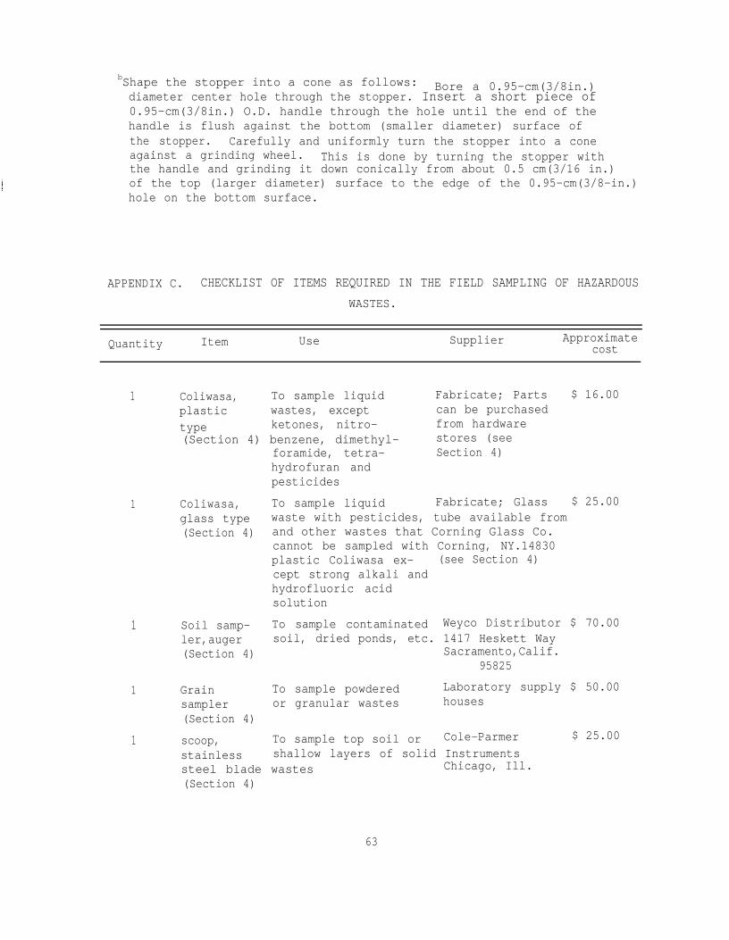
bShape the stopper into a cone as follows: Bore a 0.95-cm(3/8in.)diameter center hole through the stopper. Insert a short piece of0.95-cm(3/8in.) O.D. handle through the hole until the end of thehandle is flush against the bottom (smaller diameter) surface ofthe stopper. Carefully and uniformly turn the stopper into a coneagainst a grinding wheel. This is done by turning the stopper withthe handle and grinding it down conically from about 0.5 cm(3/16 in.)of the top (larger diameter) surface to the edge of the 0.95-cm(3/8-in.)hole on the bottom surface.
APPENDIX C. CHECKLIST OF ITEMS REQUIRED IN THE FIELD SAMPLING OF HAZARDOUSWASTES.
Quantity Item Use Supplier Approximatecost
1 Coliwasa, To sample liquid Fabricate; Parts $ 16.00plastic wastes, except can be purchasedtype ketones, nitro- from hardware(Section 4) benzene, dimethyl- stores (see
foramide, tetra- Section 4)hydrofuran andpesticides
1 Coliwasa, To sample liquid Fabricate; Glass $ 25.00glass type waste with pesticides, tube available from(Section 4) and other wastes that Corning Glass Co.
cannot be sampled with Corning, NY.14830plastic Coliwasa ex- (see Section 4)cept strong alkali andhydrofluoric acidsolution
1 Soil samp- To sample contaminated Weyco Distributor $ 70.00ler,auger soil, dried ponds, etc. 1417 Heskett Way(Section 4) Sacramento,Calif.
95825
1 Grain To sample powdered Laboratory supply $ 50.00sampler or granular wastes houses(Section 4)
1 scoop, To sample top soil or Cole-Parmer $ 25.00stainless shallow layers of solid Instrumentssteel blade wastes Chicago, Ill.(Section 4)
63
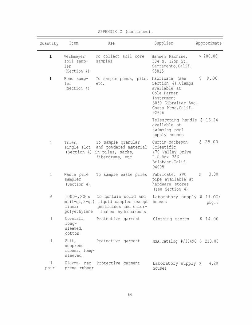
APPENDIX C (continued).
Quantity Item Use Supplier Approximate
1
1
6
1
1
1pair
Veihmeyer To collect soil coresoil samp- samplesler(Section 4)Pond samp- To sample ponds, pits,ler etc.(Section 4)
Trier, To sample granularsingle slot and powdered material(Section 4) in piles, sacks,
fiberdrums, etc.
Waste pile To sample waste pilessampler(Section 4)
l000-,200s To contain solid andml(l-qt,2-qt) liquid samples exceptlinear pesticides and chlor-polyethylene inated hydrocarbonsCoverall, Protective garmentlong-sleeved,cottonSuit, Protective garmentneoprenerubber, long-sleevedGloves, neo- Protective garmentprene rubber
64
Hansen Machine, $ 200.00334 N. 125h St.,Sacramento,Calif.95815Fabricate (see $ 9.00Section 4).Clampsavailable atCole-ParmerInstrument3060 Gibraltar Ave.Costa Mesa,Calif.92626Telescoping handle $ 16.24available atswimming poolsupply housesCurtin-Matheson $ 25.00Scientific470 Valley DriveP.O.Box 386Brisbane,Calif.94005Fabricate. PVC $ 3.00pipe available athardware stores(see Section 4)Laboratory supply $ ll.OO/houses pkg.6
Clothing stores $ 14.00
MSA,Catalog #/33496 $ 210.00
Laboratory supply $ 4.20houses

APPENDIX C (continued).
Quantity Item Use Supplier Approximatecost,
1
1
4
1pair
1
1
1
1
1
6
12each
Self-contained For use in atmospheres MSA,Catalogbreathing deficient in oxygen 8461704,apparatus or otherwise immedi- Model 401 or
Respirator, For use in atmospheres Comfo 11 Respir-chemical not immediately ator, MSA,Catalogcartridge dangerous to life # 460968type or equivalentCartridges forrespirator
For use in atmospheresnot immediatelydangerous to life
GMC Cartridge,MSACat. # 459317 & GMDCartridge, MSACat.#459318 orequivalentMSA,Cat.#79179 orequivalent
Goggles Eye protection
PortableeyewashFire extin-quisher
For emergencyeyewashFire suppression
Hard hat Head protection
Gas mask
18.9-liter(S-gal) waterin cubitaineror equivalentwith spigotTeflon linersfor Bakelitecaps
ately dangerous to equivalentlife.
For use in contami-nated atmospheresimmediately dangerousto life
MSA, Cat. #454740 orequivalentMSA, Cat. #448983 orequivalent
For miscellaneous Laboratory supplywashing purposes houses
To provide inert capliners
Sample labels, To document sampleseals, sampleanalysis re-quest sheets,chain ofcustodyrecords
65
Laboratory supplyhousesScientific ProductsS1365-1 or equiva-lent
Scientific Special-ties, P.O.Box 352Randallstown, Md.21133 or othersuppliersDesign using infor-mation from Section6
$580.00
$ 9.00
$ 5.00
$ 5.00
$ 4.00
$ 60.00
$ 5.00
$ 70.00
$ 5.50
$ 9.00

APPENDIX C (continued).
ApproximateQuantity Item Use Supplier cost
1 Field log book To keep sample records(Section 6)
1 Weighted bottom To sample storagesampler(Section 4)
1 Disposabletowels orrags
tanks or similarcontainersTo clean samplingequipment
6 Large poly-ethylene bags
12 Polyethylenebags
4 Waterproofpens
1 Technicalgradetrichloro-ethylene
1 Apron, oiland acidproof
1 Face mask
1 18.9 liter(5-gal)can
To store waste papers,rags, etc.To store samplecontainersTo complete recordsand labelsTo clean samplers
Protective garment
Protective garment
To store usedcleaning solvent
Office supply $ 2.00storesFabricate (see $ 25.00Section 4 andFigure 9)Terry towels or $ 4.00/equivalent. Avail-able at chemicalsupply housesPlastic supply $ ll.OO/houses pkg/lOOPlastic supply $ 4.00/houses pkg/lOOStationery stores $ 3.00
Chemical supply $ 22.00/stores gal.
McMaster-Carr Co. $ 9.00P.O.Box 4355Chicago, Ill.MSA $ 4.00400 Penn CenterBlvd.Pittsburg, Pa.15235Hardware stores $ 5.00
66
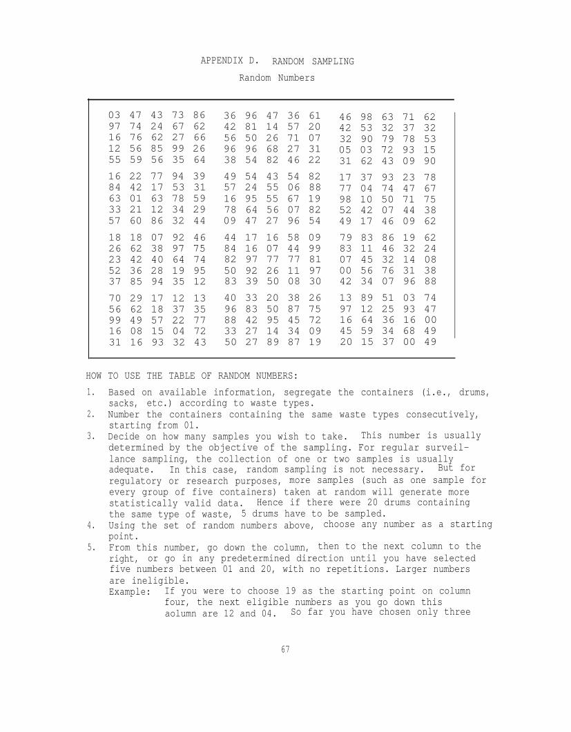
APPENDIX D. RANDOM SAMPLINGRandom Numbers
03 47 43 73 86 36 96 47 36 61 46 98 63 71 6297 74 24 67 62 42 81 14 57 20 42 53 32 37 3216 76 62 27 66 56 50 26 71 07 32 90 79 78 5312 56 85 99 26 96 96 68 27 31 05 03 72 93 1555 59 56 35 64 38 54 82 46 22 31 62 43 09 9016 22 77 94 39 49 54 43 54 82 17 37 93 23 7884 42 17 53 31 57 24 55 06 88 77 04 74 47 6763 01 63 78 59 16 95 55 67 19 98 10 50 71 7533 21 12 34 29 78 64 56 07 82 52 42 07 44 3857 60 86 32 44 09 47 27 96 54 49 17 46 09 6218 18 07 92 46 44 17 16 58 09 79 83 86 19 6226 62 38 97 75 84 16 07 44 99 83 11 46 32 2423 42 40 64 74 82 97 77 77 81 07 45 32 14 0852 36 28 19 95 50 92 26 11 97 00 56 76 31 3837 85 94 35 12 83 39 50 08 30 42 34 07 96 8870 29 17 12 13 40 33 20 38 26 13 89 51 03 7456 62 18 37 35 96 83 50 87 75 97 12 25 93 4799 49 57 22 77 88 42 95 45 72 16 64 36 16 0016 08 15 04 72 33 27 14 34 09 45 59 34 68 4931 16 93 32 43 50 27 89 87 19 20 15 37 00 49
HOW TO USE THE TABLE OF RANDOM NUMBERS:1. Based on available information, segregate the containers (i.e., drums,
sacks, etc.) according to waste types.2. Number the containers containing the same waste types consecutively,
starting from 01.3. Decide on how many samples you wish to take. This number is usually
determined by the objective of the sampling. For regular surveil-lance sampling, the collection of one or two samples is usuallyadequate. In this case, random sampling is not necessary. But forregulatory or research purposes, more samples (such as one sample forevery group of five containers) taken at random will generate morestatistically valid data. Hence if there were 20 drums containingthe same type of waste, 5 drums have to be sampled.
4. Using the set of random numbers above, choose any number as a startingpoint.
5. From this number, go down the column, then to the next column to theright, or go in any predetermined direction until you have selectedfive numbers between 01 and 20, with no repetitions. Larger numbersare ineligible.Example: If you were to choose 19 as the starting point on column
four, the next eligible numbers as you go down thisaolumn are 12 and 04. So far you have chosen only three
67
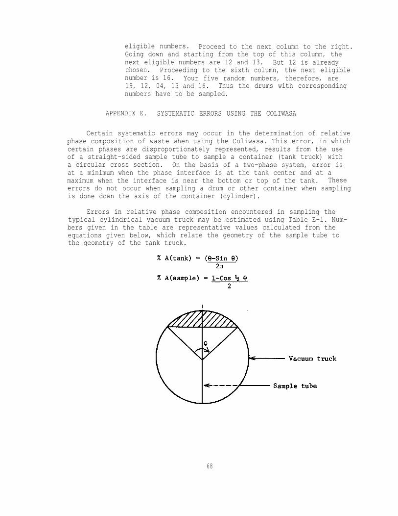
eligible numbers. Proceed to the next column to the right.Going down and starting from the top of this column, thenext eligible numbers are 12 and 13. But 12 is alreadychosen. Proceeding to the sixth column, the next eligiblenumber is 16. Your five random numbers, therefore, are19, 12, 04, 13 and 16. Thus the drums with correspondingnumbers have to be sampled.
APPENDIX E. SYSTEMATIC ERRORS USING THE COLIWASA
Certain systematic errors may occur in the determination of relativephase composition of waste when using the Coliwasa. This error, in whichcertain phases are disproportionately represented, results from the useof a straight-sided sample tube to sample a container (tank truck) witha circular cross section. On the basis of a two-phase system, error isat a minimum when the phase interface is at the tank center and at amaximum when the interface is near the bottom or top of the tank. Theseerrors do not occur when sampling a drum or other container when samplingis done down the axis of the container (cylinder).
Errors in relative phase composition encountered in sampling thetypical cylindrical vacuum truck may be estimated using Table E-l. Num-bers given in the table are representative values calculated from theequations given below, which relate the geometry of the sample tube tothe geometry of the tank truck.
68
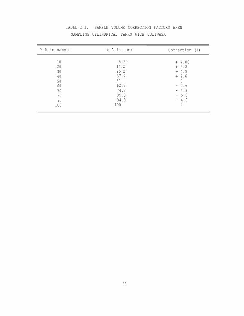
TABLE E-l. SAMPLE VOLUME CORRECTION FACTORS WHENSAMPLING CYLINDRICAL TANKS WITH COLIWASA
% A in sample % A in tank Correction (%)
10 5.20 + 4.8020 14.2 + 5.830 25.2 + 4.840 37.4 + 2.650 50 060 62.6 - 2.670 74.8 - 4.880 85.8 - 5.890 94.8 - 4.8
100 100 0
69

