sample maam
TRANSCRIPT
8/9/2019 Sample maam
http://slidepdf.com/reader/full/sample-maam 1/37
Chapter 1
INTRODUCTION
A toll road or tollway is a privately or publicly built road for which a driver pays
a toll (fee) for use. Structures for which tolls are charged include toll bridges and toll
tunnels. Non-toll roads are financed using other sources of revenue, most typically
fuel tax or general tax funds. The building or facility in which a toll is collected may be
called a toll booth, toll plaza, toll station, toll bar or toll gate. This building is usually
found on either side of a bridge and at exits.
Tolls have been placed on roads at various times in history, often to generate
funds for repayment of toll revenue bonds used to financed constructions and
operations. Toll roads are at least 2700 years old, as tolls had to be paid by
travelers. Many European roads were originally constructed as toll roads in order to
recoup the costs of construction. Three systems of toll roads then exist: open (with
mainline barriers); closed (with entry/exits tolls) and electronic toll collection (no toll
booth, only electronic toll collection gantries at entrances and exits).
Modern toll roads uses either or combination of the three systems. Electronic
toll collection is considered to be the newest technology system of today or the RFID
(Radio-frequency Identification) technology. The electronic system determines
whether the passing car is enrolled in the program, alerts enforcers if not. The
accounts of registered cars are debited automatically without stopping or even
1
8/9/2019 Sample maam
http://slidepdf.com/reader/full/sample-maam 2/37
opening a window. The system uses a radio transponder mounted in the vehicle to
deduct toll fees from a prepaid account as it passes through the barrier.
The electronic system is convenient in such a way that it lessens the delay in
toll collection but just recently, the Philippines did not approved the approach and
was questioned by the law due to direct implementations without prior notice. The
new technology was quite expensive and needed to be studied well. According to
some feedbacks, computer glitch can result in delays several miles long. Besides,
not all commuters have credit cards that are required in the system. Finally, the last
concern would be regarding privacy matters. Due to the usage of radio frequency
signals, the commuters can be possibly trace which most citizens does not agree
upon.
Considering some of the factors and drawbacks of the latest technology in
the tollway system, the proponents still wishes to create a system that would be
beneficial and would still lessen the errors and will not require a large amount of
personnel. These concerns led the proponents to design a much simpler and
effective tollway system that would somehow be convenient for all types of masses
that could be easily afforded and adapted.
2

8/9/2019 Sample maam
http://slidepdf.com/reader/full/sample-maam 3/37
BACKGROUND OF THE PROJECT
Economic Feasibility
Table 1.Costing of Materials
3
Item Price
PIC168F84A
Motor
Casing
Hook up wire / Telephone wire
Soldering lead
Coin slot
Relay
Switch
Capacitor, Resistor
Hi-end led
UPSLDR
Phototransistor
Lock
PBC Pipe
Transistor
BA6218
Misc.
1200.00
300.00
5000.00
400.00
200.00
1300.00
280.00
250.00
150.00
70.00
1800.0030.00
200.00
200.00
155.00
270.00
175.00
500.00
TOTAL Php 8,000.00
8/9/2019 Sample maam
http://slidepdf.com/reader/full/sample-maam 4/37
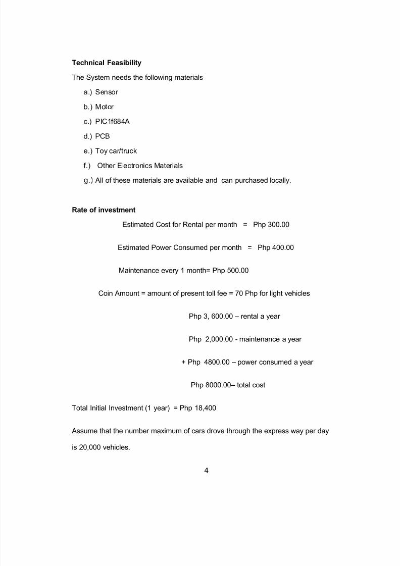
Technical Feasibility
The System needs the following materials
a.) Sensor
b.) Motor
c.) PIC1f684A
d.) PCB
e.) Toy car/truck
f.) Other Electronics Materials
g.) All of these materials are available and can purchased locally.
Rate of investment
Estimated Cost for Rental per month = Php 300.00
Estimated Power Consumed per month = Php 400.00
Maintenance every 1 month= Php 500.00
Coin Amount = amount of present toll fee = 70 Php for light vehicles
Php 3, 600.00 – rental a year
Php 2,000.00 - maintenance a year
+ Php 4800.00 – power consumed a year
Php 8000.00– total cost
Total Initial Investment (1 year) = Php 18,400
Assume that the number maximum of cars drove through the express way per day
is 20,000 vehicles.
4
8/9/2019 Sample maam
http://slidepdf.com/reader/full/sample-maam 5/37
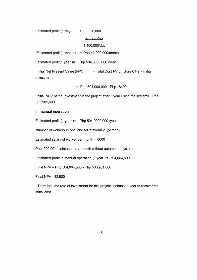
Estimated profit (1 day) = 20,000
X 70 Php
1,400,000/day
Estimated profit(1 month) = Php 42,000,000/month
Estimated profit(1 year )= Php 504,0000,000 /year
Initial Net Present Value (NPV) = Total Cost PV of future CF’s – Initial
Investment
= Php 504,000,000– Php 18400
Initial NPV of the Investment in the project after 1 year using the system= Php
503,981,600
In manual operation
Estimated profit (1 year )= Php 504,0000,000 /year
Number of workers in one lane toll station= 2 (person)
Estimated salary of worker per month = 8000
Php 500.00 - maintenance a month without automated system
Estimated profit in manual operation (1 year ) = 504,064,500
Final NPV = Php 504,064,500 - Php 503,981,600
Final NPV= 82,900
Therefore, the rate of investment for this project is almost a year to recover the
initial cost.
5
8/9/2019 Sample maam
http://slidepdf.com/reader/full/sample-maam 6/37
Statement of the Problem
The proponents aim to design a Tollway System that helps answer the
following questions:
1. Does a tollway lessen the error in manual operation?
2. Does a huge number of personnel in tollway station add to the booming
expenses of the tollway system owners/government?
3. Does a tollway system enable, businessman, owners/government save
money and investment on the maintenance?
Objectives of the Project
The general objective of this project is to design a tollway. It specifically aims
to:
1. Create a design on tollway system for tollway owner that is easy to
manage and will lessen error in manual operation.
2. Design a tollway system that will not require a huge number of personnel
to pay for maintenance operation.
3. Design a tollway system that will save time and money for tollway owners.
6
8/9/2019 Sample maam
http://slidepdf.com/reader/full/sample-maam 7/37
Significance of the Study
The project design focuses on the development of the Automated Tollway
System. It is conceptualized to address the problem in accessibility and convenience
of tollway system services.
The project system will be used for business. It works similarly on other coin-
slot machines or services such as vending machines, video games and many others.
Scope and Limitation
The System has the following features:
1. The system consists of a coin slot that is allotted for the 1 token.
2. The gate in the entrance will open if the sensor detects a vehicle.
3. When the sensor detects that a car already entered the gate, the entrance
gate will close.
4. The gate at the back will open if a coin is dropped in the coin slot.
5. Then the back gate will close again if the sensor detects that the vehicle had
already passed.
6. The system has a weighing scale that determines the weight of vehicles.
7. The system has a power backup in case of power interruptions.
7
8/9/2019 Sample maam
http://slidepdf.com/reader/full/sample-maam 8/37
The System has the following limitations:
1. The entire system is electrically operated.
2. The slot can only accept one token that has a corresponding value.
3. The system can only accommodate one vehicle at a time.
4. The power backup will last for maximum of one hour only.
5. The token can only be purchased to certified outlets and official distributors
such as gasoline stations, department stores and many more.
8
* Create a design
on tollway system
for tollway owner
that is easy to
manage and
lessen error in
manual operation.
* Design a tollwaysystem that will notrequire a hugenumber of
personnel to payfor maintenanceo eration.
8/9/2019 Sample maam
http://slidepdf.com/reader/full/sample-maam 9/37
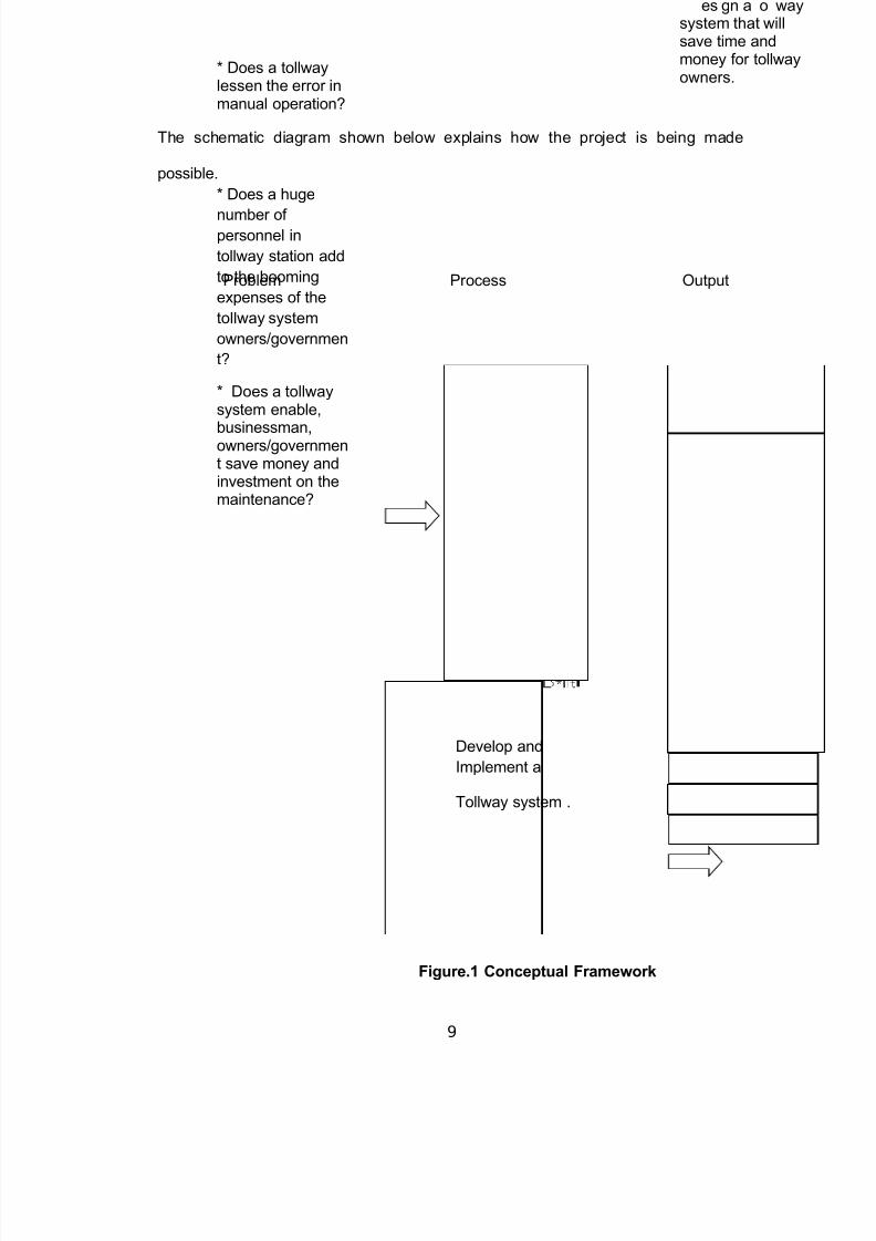
The schematic diagram shown below explains how the project is being made
possible.
Figure.1 Conceptual Framework
9
* Does a tollwaylessen the error inmanual operation?
* Does a huge
number of personnel in
tollway station add
to the booming
expenses of the
tollway system
owners/governmen
t?
* Does a tollwaysystem enable,
businessman,owners/government save money andinvestment on themaintenance?
Problem Process Output
Develop and
Implement a
Tollway system .
es gn a o waysystem that willsave time andmoney for tollwayowners.
8/9/2019 Sample maam
http://slidepdf.com/reader/full/sample-maam 10/37
Definition of Terms
Tollway - is a privately or publicly built road for which a driver pays a toll (a fee) for
use.
Automation - the use of control systems (such as numerical control, programmable
logic control, and other industrial control systems), in concert with other applications
of information technology (such as computer-aided technologies [CAD, CAM, CAx]),
to control industrial machinery and processes, reducing the need for human
intervention.
Machine - any mechanical or electrical device that transmits or modifies energy to
perform or assist in the performance of tasks. It normally requires an input as a
trigger, transmits the modified energy to an output, which performs the desired task
alternative to the more complex dot-matrix displays.
Switch- an electrical component that can break an electrical circuit, interrupting the
current or diverting it from one conductor to another.
Direct current or DC motor - converts electrical energy into mechanical energy.
PIC16F84A - an 8-bit microcontroller of RISC (Reduced Instruction Set Computer)
architecture. It uses a total number of 35 instructions. It has a total of 18 pins and is
mostly found in a DIP18 type of case.
Token coin - a piece of metal or other composition used as a substitute for currency;
includes subway tokens.
10
8/9/2019 Sample maam
http://slidepdf.com/reader/full/sample-maam 11/37
Resistor - a two-terminal electronic component that produces a voltage across its
terminals that is proportional to the electric current through it in accordance with
Ohm's law.
Capacitor or condenser - a passive electronic component consisting of a pair of
conductors separated by a dielectric.
Light-emitting diode (LED) - an electronic light source.
Radio-frequency identification (RFID) - is the use of an object applied to or
incorporated into a product, animal, or person for the purpose of identification and
tracking using radio waves.
Microcontroller - A single chip that contains the processor (the CPU), non-volatile
memory for the program (ROM or flash), volatile memory for input and output (RAM),
a clock and an I/O control unit.
11
8/9/2019 Sample maam
http://slidepdf.com/reader/full/sample-maam 12/37
Chapter II
REVIEW OF RELATED LITERATURES AND STUDIES
Review of Related Literatures
A toll road (or tollway, turnpike, pike, toll highway or an express toll route) is a
privately or publicly built road for which a driver pays a toll (a fee) for use. Structures
for which tolls are charged include toll bridges and toll tunnels. Non-toll roads are
financed using other sources of revenue, most typically fuel tax or general tax funds.
The building or facility in which a toll is collected may be called a toll booth, toll plaza,
toll station, toll bar or toll gate. This building is usually found on either side of a bridge
and at exits.
Three systems of toll roads exist: open (with mainline barrier toll
plazas); closed (with entry/exit tolls) and all-electronic toll collection (no toll booths,
only electronic toll collection gantries at entrances and exits, or at strategic locations
on the mainline of the road).
On an open toll system, all vehicles stop at various locations along the
highway to pay a toll. While this may save money from the lack of need to construct
tolls at every exit, it can cause traffic congestion, and drivers may be able to avoid
tolls (shunpike) by exiting and re-entering the highway.
12
8/9/2019 Sample maam
http://slidepdf.com/reader/full/sample-maam 13/37
With a closed system, vehicles collect a ticket when entering the highway. In
some cases, the ticket displays the toll to be paid on exit. Upon exit, the driver must
pay the amount listed for the given exit. Should the ticket be lost, a driver must
typically pay the maximum amount possible for travel on that highway. Short toll
roads with no intermediate entries or exits may have only one toll plaza at one end,
with motorists traveling in either direction paying a flat fee either when they enter or
when they exit the toll road. In a variant of the closed toll system, mainline barriers
are present at the two endpoints of the toll road, and each interchange has a ramp
toll that is paid upon exit or entry. In this case, a motorist pays a flat fee at the ramp
toll and another flat fee at the end of the toll road; no ticket is necessary.
In an all-electronic system (such as that used on Highway 407 in the
Canadian province of Ontario and the Fort Bend Westpark Tollway in the U.S. state
of Texas), no cash toll collection takes place, tolls are usually collected with the use
of a transponder mounted on the windshield of each vehicle, which is linked to a
customer account which is debited for each use of the toll road. On some roads,
such as Highway 407, automobiles and light trucks without transponders are
permitted to use the road (though trucks with a gross vehicle weight over 5,000
kilograms must have a transponder)[1] - a bill for the toll due is then sent to the
registered owner of the vehicle by mail; by contrast, the Fort Bend Westpark Tollway
requires all vehicles to be equipped with a transponder
Modern toll roads often use a combination of the three, with various entry and
exit tolls supplemented by occasional mainline tolls.
13
8/9/2019 Sample maam
http://slidepdf.com/reader/full/sample-maam 14/37
Some toll roads charge a toll in only one direction, such as where the M4 in
Great Britain crosses the River Severn on either of the two Severn Bridges. On these
bridges, it is free to travel from Wales into England, but a toll must be paid on the
return journey. This is only practical where the detour to avoid the toll is very large –
in this case about 40 miles.
Toll payments may be made in cash, by credit card, by pre-paid card, or by
an electronic toll collection system. In some European countries, payment is made
using stickers which are affixed to the windscreen. Some toll booths are automated.
Tolls may vary according to the distance traveled, the building and maintenance
costs of the motorway, and the type of vehicle.
Tolls have been placed on roads at various times in history, often to generate
funds for repayment of toll revenue bonds used to finance constructions and/or
operation
Toll roads are at least 2700 years old, as tolls had to be paid by travellers
using the Susa–Babylon highway under the regime of Ashurbanipal, who reigned in
the seventh century BC.[3] Aristotle and Pliny refer to tolls in Arabia and other parts
of Asia. In India, before the 4th century BC, the Arthasastra notes the use of tolls.
Germanic tribes charged tolls to travellers across mountain passes. Tolls were used
in the Holy Roman Empire in the 14th century and 15th century.
A 14th century example (though not for a road) is Castle Loevestein in the
Netherlands, which was built at a strategic point where 2 rivers meet, and charged
tolls on boats sailing along the river.
14
8/9/2019 Sample maam
http://slidepdf.com/reader/full/sample-maam 15/37
Many modern European roads were originally constructed as toll roads in
order to recoup the costs of construction. In 14th century England, some of the most
heavily used roads were repaired with money raised from tolls by pavage grants.
Turnpike trusts were established in England from 1706 onwards, and were ultimately
responsible for the maintenance and improvement of most main roads in England
and Wales, until they were gradually abolished from the 1870s. Most trusts improved
existing roads, but some new ones, usually only short stretches of road, were also
built. Thomas Telford's Holyhead road (now the A5 road) is exceptional as a
particularly long new road, built in the early 19th century with many toll booths along
its length. See also Toll roads in the United Kingdom.
One of the first U.S. toll roads, the Long Island Motor Parkway (which opened
on October 10, 1908) was built by William Kissam Vanderbilt II, the great-grandson
of Cornelius Vanderbilt. The road was closed in 1938 when it was taken over by the
state of New York in lieu of back taxes
Toll roads are found in many countries. The way they are funded and
operated may differ from country to country. Some of these toll roads are privately
owned and operated. Others are owned by the government. Some of the
government-owned toll roads are privately operated.
Some toll roads are managed under such systems as the Build-Operate-
Transfer (BOT) system. Private companies build the roads and are given a limited
franchise. Ownership is transferred to the government when the franchise expires.
Throughout the world, this type of arrangement is prevalent in Australia, India, South
15

8/9/2019 Sample maam
http://slidepdf.com/reader/full/sample-maam 16/37
Korea, Japan, Philippines, and Canada. The (BOT) system is a fairly new concept
that is gaining ground in the United States, with Arkansas, California, Delaware,
Florida, Illinois, Indiana, Mississippi[6], Texas, and Virginia already building and
operating toll roads under this scheme. Pennsylvania, Massachusetts, New Jersey,
and Tennessee are also considering the BOT methodology for future highway
projects.
The more traditional means of managing toll roads in the United States is
through semi-autonomous public authorities. New York, Massachusetts, New
Hampshire, New Jersey, Maryland, Ohio, Pennsylvania, Kansas, Oklahoma, and
West Virginia manage their toll roads in this manner. While most of the toll roads in
California, Delaware, Florida, Texas, and Virginia are operating under the BOT
arrangement, a few of the older toll roads in these states are still operated by public
authorities.
Review of Related Studies
An adaptation of military "identification friend or foe" or RFID technology,
called electronic toll collection, is lessening the delay incurred in toll collection. The
electronic system determines whether a passing car is enrolled in the program, alerts
enforcers if it is not. The accounts of registered cars are debited automatically
without stopping or even opening a window. Currently, DSRC is used as a wireless
protocol. Other systems are based on GPRS/GSM and GPS technology. Such a
16
8/9/2019 Sample maam
http://slidepdf.com/reader/full/sample-maam 17/37
system (for trucks only) in Germany launched successfully[citation needed] in
January 2005 and by the end of its first year of operation will have charged tolls for
around 22 billion driven kilometres. One of the advantages of GPS-based systems is
their ability to adapt easily and quickly to changes in charge parameters (road
classes, vehicle types, emission levels, time slots, etc.). Another advantage is the
systems' ability to support other value-added services on the same technology
platform. These services might include fleet and vehicle engine management
systems, emergency response services, pay-as-you-drive insurance services and
navigation capabilities.
The first major deployment of an RFID electronic toll collection system in the
United States was on the Dallas North Tollway in 1989 by Amtech (see TollTag). The
Amtech RFID technology used on the Dallas North Tollway was originally developed
at Sandia Labs for use in tagging and tracking livestock. In the same year, the
Telepass active transponder RFID system was introduced across Italy.
Highway 407 in the province of Ontario, Canada has no toll booths, and
instead reads a transponder mounted on the windshields of each vehicle using the
road (the rear license plates of vehicles lacking a transponder are photographed
when they enter and exit the highway). This made the highway the first all-automated
highway in the world. A bill is mailed monthly for usage of the 407. Lower charges
are levied on frequent 407 users who carry electronic transponders in their vehicles.
The approach has not been without controversy.
17
8/9/2019 Sample maam
http://slidepdf.com/reader/full/sample-maam 18/37
Chapter III
METHODOLOGY
This chapter presents the methods and the procedures used in the project.
The topics included here were the method used, locale of the study, the instrument
used in making the project.
Method Used
The project used laboratory experimental research to test the functionality of
the automated tollway using a coin sensor.
Locale of the Study
The project was conducted at University of Southern Mindanao, started on
December 2009 until March 2010
Project Instrument
The project design was tested using the hardware and software simulation.
Target board and electronics component were used in hardware. Proteus
applications were used in software
18

8/9/2019 Sample maam
http://slidepdf.com/reader/full/sample-maam 19/37
APPENDICES
19
8/9/2019 Sample maam
http://slidepdf.com/reader/full/sample-maam 20/37
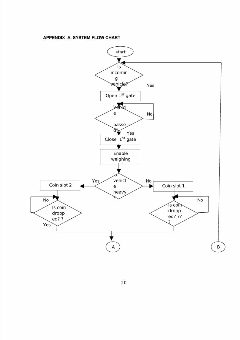
APPENDIX A. SYSTEM FLOW CHART
Yes
No
Yes
Yes
Yes No
No No
no
No
Yes
20
start
Is
incomin
g
vehicle?
Open 1ST gate
Vehicl
e
passe
d?
Is
vehicl
e
heavy
?
Close 1ST gate
Enable
weighing
Coin slot 1
Is coin
dropp
ed? ??
?
Coin slot 2
Is coin
dropp
ed? ?
A B
8/9/2019 Sample maam
http://slidepdf.com/reader/full/sample-maam 21/37
RB0=
1?
RB3=
=1?
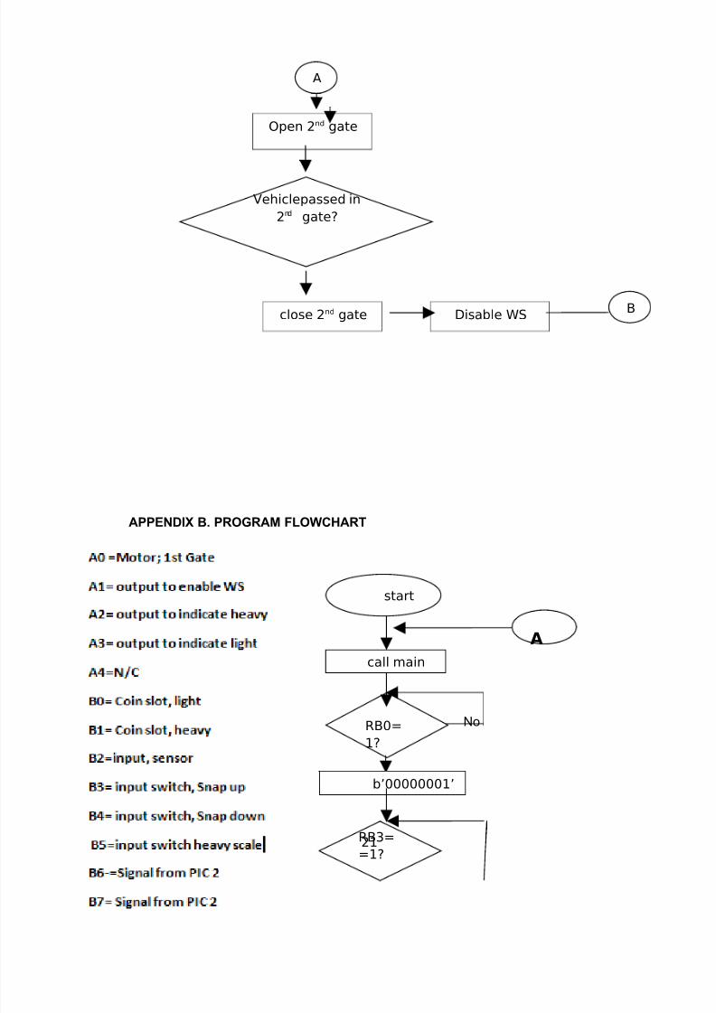
APPENDIX B. PROGRAM FLOWCHART
Legend:
No
21
Open 2nd gate
Vehiclepassed in
2nd gate?
close 2nd gate Disable WS
start
call main
b’00000001’
A
A
B
8/9/2019 Sample maam
http://slidepdf.com/reader/full/sample-maam 22/37
RB4=
=?
RB2=
=1?
RB0=
1?
No
Yes
No
Yes
No
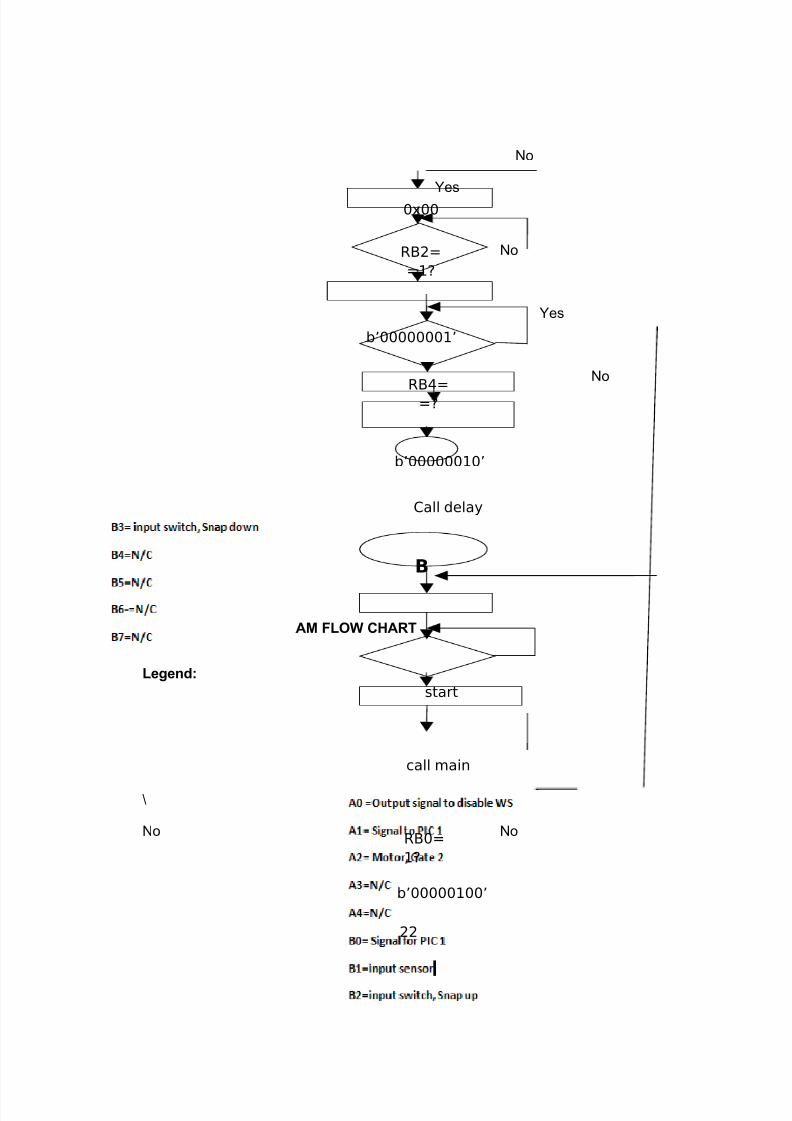
APPENDIX B.1 PROGRAM FLOW CHART
Legend:
\
No No
22
0x00
b’00000001’
b’00000010’
Call delay
B
start
call main
b’00000100’
8/9/2019 Sample maam
http://slidepdf.com/reader/full/sample-maam 23/37
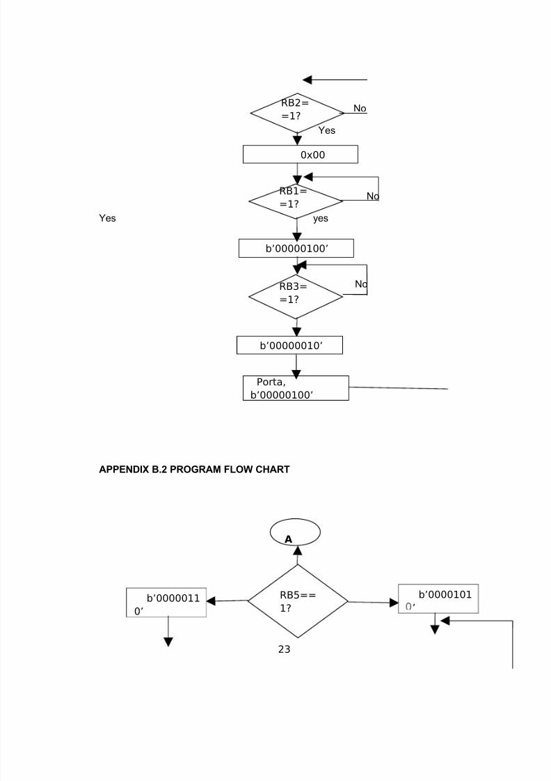
RB2=
=1?
RB3=
=1?
RB1=
=1?
No
Yes
No
Yes yes
No
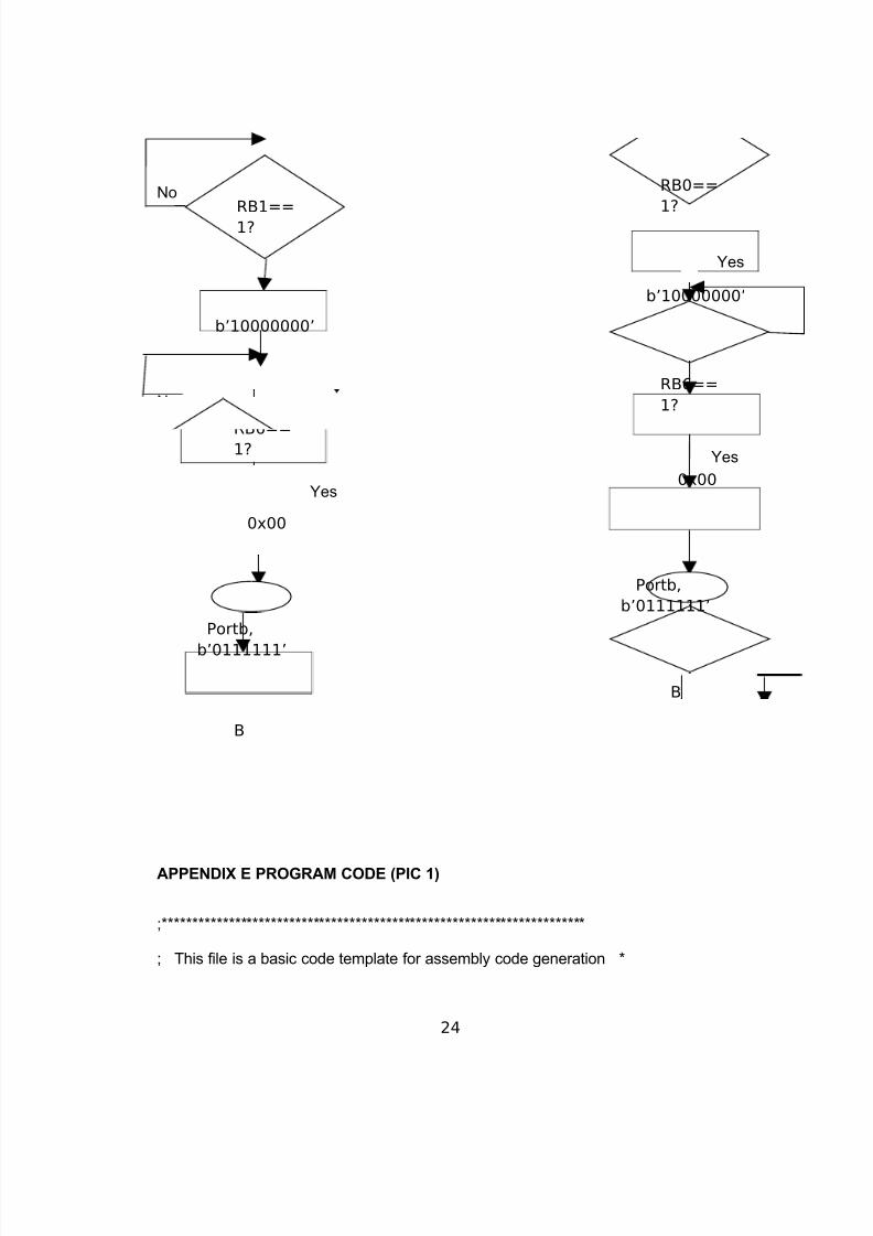
APPENDIX B.2 PROGRAM FLOW CHART
23
0x00
b’00000100’
b’00000010’
Porta,
b’00000100’
A
RB5==
1?
b’0000101
’b’0000011
0’
8/9/2019 Sample maam
http://slidepdf.com/reader/full/sample-maam 24/37
RB6==
1?
RB6==1?
No No
Yes
Yes
No
Yes
Yes
APPENDIX E PROGRAM CODE (PIC 1)
;**********************************************************************
; This file is a basic code template for assembly code generation *
24
RB0==
1?
b’10000000’
0x00
Portb,
b’0111111’
B
RB1==
1?
b’10000000’
0x00
Portb,
b’0111111’
B
8/9/2019 Sample maam
http://slidepdf.com/reader/full/sample-maam 25/37
; on the PIC16F84A. This file contains the basic code *
; building blocks to build upon. *
; *
; Refer to the MPASM User's Guide for additional information on *
; features of the assembler (Document DS33014). *
; *
; Refer to the respective PIC data sheet for additional *
; information on the instruction set. *
; *
;**********************************************************************
; *
; Filename: xxx.asm *
; Date: *
; File Version: *
; *
; Author: *
; Company: *
; *
; *
;**********************************************************************
; *
; Files Required: P16F84A.INC *
; *
;**********************************************************************
; *
25
8/9/2019 Sample maam
http://slidepdf.com/reader/full/sample-maam 26/37
; Notes: *
; *
;**********************************************************************
list p=16F84A ; list directive to define processor
#include <p16F84A.inc> ; processor specific variable definitions
__CONFIG _CP_OFF & _WDT_OFF & _PWRTE_ON & _RC_OSC
; '__CONFIG' directive is used to embed configuration data within .asm file.
; The lables following the directive are located in the respective .inc file.
; See respective data sheet for additional information on configuration word.
;***** VARIABLE DEFINITIONS
w_temp EQU 0x0C ; variable used for context saving
status_temp EQU 0x0D ; variable used for context saving
porta equ 0x05
portb equ 0x06
mcount equ 0x0c
ncount equ 0x0d
;**********************************************************************
26
8/9/2019 Sample maam
http://slidepdf.com/reader/full/sample-maam 27/37
ORG 0x000 ; processor reset vector
goto main ; go to beginning of program
ORG 0x004 ; interrupt vector location
movwf w_temp ; save off current W register contents
movf STATUS,w ; move status register into W register
movwf status_temp ; save off contents of STATUS register
; isr code can go here or be located as a call subroutine elsewhere
movf status_temp,w ; retrieve copy of STATUS register
movwf STATUS ; restore pre-isr STATUS register contents
swapf w_temp,f
swapf w_temp,w ; restore pre-isr W register contents
retfie ; return from interrupt
main
movlw 0x00
tris porta
movlw b'01111111'
27
8/9/2019 Sample maam
http://slidepdf.com/reader/full/sample-maam 28/37
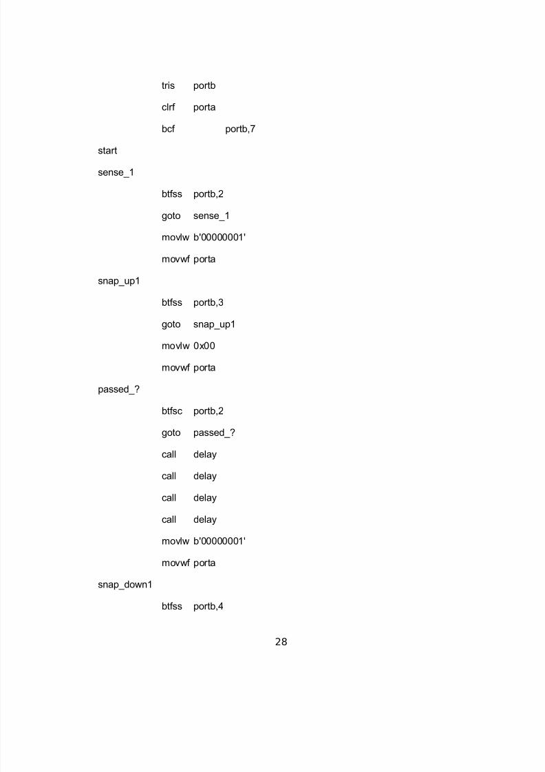
tris portb
clrf porta
bcf portb,7
start
sense_1
btfss portb,2
goto sense_1
movlw b'00000001'
movwf porta
snap_up1
btfss portb,3
goto snap_up1
movlw 0x00
movwf porta
passed_?
btfsc portb,2
goto passed_?
call delay
call delay
call delay
call delay
movlw b'00000001'
movwf porta
snap_down1
btfss portb,4
28
8/9/2019 Sample maam
http://slidepdf.com/reader/full/sample-maam 29/37
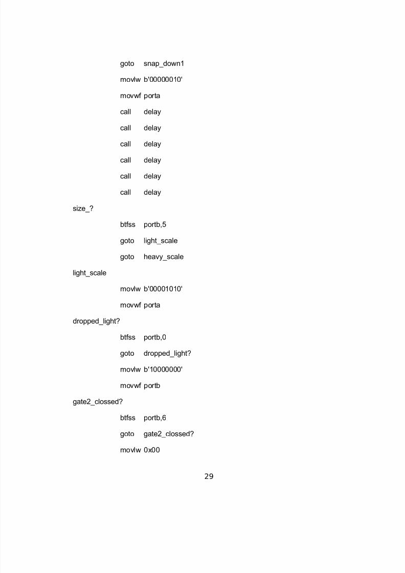
goto snap_down1
movlw b'00000010'
movwf porta
call delay
call delay
call delay
call delay
call delay
call delay
size_?
btfss portb,5
goto light_scale
goto heavy_scale
light_scale
movlw b'00001010'
movwf porta
dropped_light?
btfss portb,0
goto dropped_light?
movlw b'10000000'
movwf portb
gate2_clossed?
btfss portb,6
goto gate2_clossed?
movlw 0x00
29
8/9/2019 Sample maam
http://slidepdf.com/reader/full/sample-maam 30/37
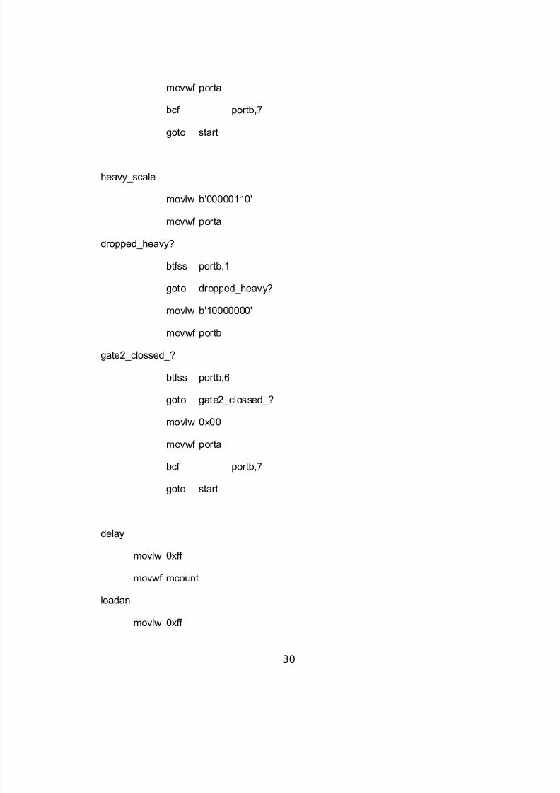
movwf porta
bcf portb,7
goto start
heavy_scale
movlw b'00000110'
movwf porta
dropped_heavy?
btfss portb,1
goto dropped_heavy?
movlw b'10000000'
movwf portb
gate2_clossed_?
btfss portb,6
goto gate2_clossed_?
movlw 0x00
movwf porta
bcf portb,7
goto start
delay
movlw 0xff
movwf mcount
loadan
movlw 0xff
30

8/9/2019 Sample maam
http://slidepdf.com/reader/full/sample-maam 31/37
movwf ncount
decn
decfsz ncount,f
goto decn
decfsz mcount,f
goto loadan
return
END
31
8/9/2019 Sample maam
http://slidepdf.com/reader/full/sample-maam 32/37
APPENDIX E.1 PROGRAM CODE (PIC 2)
;**********************************************************************
; This file is a basic code template for assembly code generation *
; on the PIC16F84A. This file contains the basic code *
; building blocks to build upon. *
; *
; Refer to the MPASM User's Guide for additional information on *
; features of the assembler (Document DS33014). *
; *
; Refer to the respective PIC data sheet for additional *
; information on the instruction set. *
; *
;**********************************************************************
; *
; Filename: xxx.asm *
; Date: *
; File Version: *
; *
; Author: *
; Company: *
; *
32
8/9/2019 Sample maam
http://slidepdf.com/reader/full/sample-maam 33/37
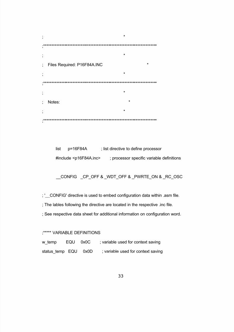
; *
;**********************************************************************
; *
; Files Required: P16F84A.INC *
; *
;**********************************************************************
; *
; Notes: *
; *
;**********************************************************************
list p=16F84A ; list directive to define processor
#include <p16F84A.inc> ; processor specific variable definitions
__CONFIG _CP_OFF & _WDT_OFF & _PWRTE_ON & _RC_OSC
; '__CONFIG' directive is used to embed configuration data within .asm file.
; The lables following the directive are located in the respective .inc file.
; See respective data sheet for additional information on configuration word.
;***** VARIABLE DEFINITIONS
w_temp EQU 0x0C ; variable used for context saving
status_temp EQU 0x0D ; variable used for context saving
33
8/9/2019 Sample maam
http://slidepdf.com/reader/full/sample-maam 34/37
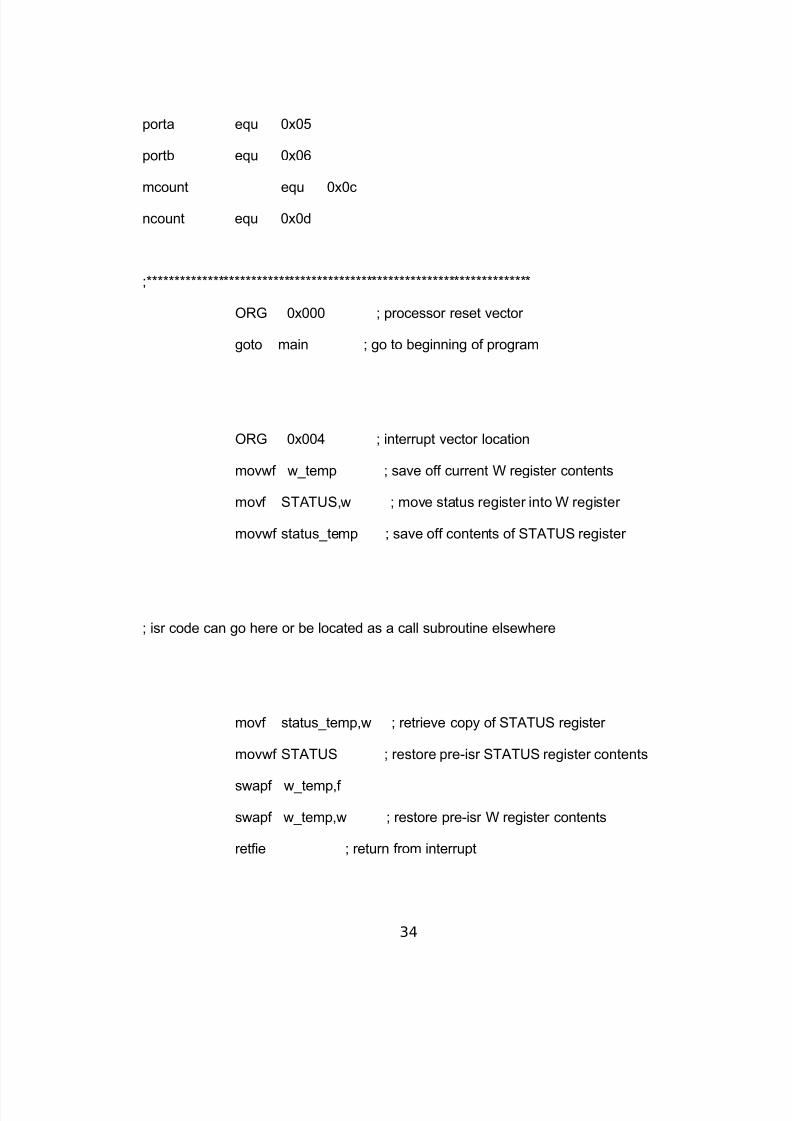
porta equ 0x05
portb equ 0x06
mcount equ 0x0c
ncount equ 0x0d
;**********************************************************************
ORG 0x000 ; processor reset vector
goto main ; go to beginning of program
ORG 0x004 ; interrupt vector location
movwf w_temp ; save off current W register contents
movf STATUS,w ; move status register into W register
movwf status_temp ; save off contents of STATUS register
; isr code can go here or be located as a call subroutine elsewhere
movf status_temp,w ; retrieve copy of STATUS register
movwf STATUS ; restore pre-isr STATUS register contents
swapf w_temp,f
swapf w_temp,w ; restore pre-isr W register contents
retfie ; return from interrupt
34
8/9/2019 Sample maam
http://slidepdf.com/reader/full/sample-maam 35/37
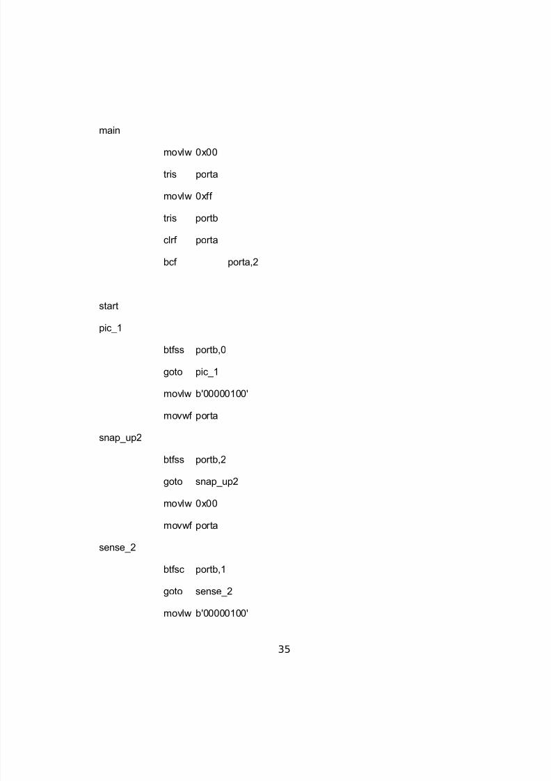
main
movlw 0x00
tris porta
movlw 0xff
tris portb
clrf porta
bcf porta,2
start
pic_1
btfss portb,0
goto pic_1
movlw b'00000100'
movwf porta
snap_up2
btfss portb,2
goto snap_up2
movlw 0x00
movwf porta
sense_2
btfsc portb,1
goto sense_2
movlw b'00000100'
35

8/9/2019 Sample maam
http://slidepdf.com/reader/full/sample-maam 36/37
movwf porta
snap_down2
btfss portb,3
goto snap_down2
movlw b'00000010' ;send to pic1
movwf porta
bcf porta,2
movlw b'00000001'
movwf porta
call delay
call delay
call delay
goto main
delay
movlw 0xff
movwf mcount
loadan
movlw 0xff
movwf ncount
decn
decfsz ncount,f
goto decn
decfsz mcount,f
goto loadan
36

8/9/2019 Sample maam
http://slidepdf.com/reader/full/sample-maam 37/37