maam-011206 - macom darlington amplifier dc-15 ghz rev. v1 maam-011206 11 macom technology solutions...
TRANSCRIPT

Broadband Darlington Amplifier DC-15 GHz
Rev. V1
MAAM-011206
1 1
MACOM Technology Solutions Inc. (MACOM) and its affiliates reserve the right to make changes to the product(s) or information contained herein without notice. Visit www.macom.com for additional data sheets and product information.
For further information and support please visit: https://www.macom.com/support
DC-0009466
1
Features
Gain: 13.5 dB @ 6 GHz
Output P1dB: 18 dBm @ 6 GHz
Noise figure: 4.5 dB @ 6 GHz
Single Bias Operation
Adjustable Current
Lead-Free 1.5 x 1.2 mm 6-lead TDFN Plastic Package
Halogen–Free ―Green‖ Mold Compound
RoHS* Compliant
Description
The MAAM-011206 is a versatile, DC - 15 GHz, Darlington amplifier, with 13.5 dB typical gain and 18 dBm of output power. The input and output are fully matched to 50 Ω with typical return loss >10 dB. Third order linearity (OIP3) is typically 28 dBm and reverse isolation is >21 dB. Functional operation is achieved with a single bias voltage VDD, from +3 V to +5 V. An external resistor between VDD and pin 6 enables single bias operation. No negative bias is necessary. See DC Bias Operation table for external resistor value selection. The MAAM-011206 is housed in a leadless 1.5 x 1.2 mm plastic SMT package compatible with standard pick and place assembly equipment. It is fabricated using a GaAs process which features full passivation for increased performance and reliability. The device is well suited to diverse applications such as LO drivers, gain blocks and RF driver stages.
Ordering Information1,2
* Restrictions on Hazardous Substances, European Union Directive 2011/65/EU.
1. Reference Application Note M513 for reel size information. 2. All sample boards include 3 loose parts.
Functional Schematic
Pin Configuration3,4
Pin No. Pin Name Description
1 RFOUT / VDD RF Output / Drain Bias
2 N/C No Connection3
3 RFIN RF Input
4 N/C No Connection3
5 N/C No Connection3
6 VB Bias Adjust
3. MACOM recommends connecting unused package pins to ground.
4. The exposed pad centered on the package bottom must be connected to RF, DC and thermal ground.
Part Number Package
MAAM-011206-TR1000 1000 Piece Reel
MAAM-011206-TR3000 3000 Piece Reel
MAAM-011206-SMB Sample Board

Broadband Darlington Amplifier DC-15 GHz
Rev. V1
MAAM-011206
2 2
MACOM Technology Solutions Inc. (MACOM) and its affiliates reserve the right to make changes to the product(s) or information contained herein without notice. Visit www.macom.com for additional data sheets and product information.
For further information and support please visit: https://www.macom.com/support
DC-0009466
2
Electrical Specifications: TA = 25°C, VDD = +5 V, VB 5 = 1.5 V , Z0 = 50 Ω
Parameter Test Conditions Units Min. Typ. Max.
Gain
1 GHz 6 GHz 12 GHz 15 GHz
dB
— 11.5 9.5 —
15.0 13.5 11.0 10.0
—
Isolation 0.1 - 15 GHz dB — 22 —
Input Return Loss 0.1 - 15 GHz dB — 15 —
Output Return Loss 0.1 - 15 GHz dB — 15 —
Noise Figure
1 GHz 6 GHz 12 GHz 15 GHz
dB —
4.0 4.5 6.0 7.0
—
Output PSAT
1 GHz 6 GHz 12 GHz 15 GHz
dBm —
19.0 20.0 18.0 16.0
—
Output Power
PIN = 6.5 dBm 1 GHz 6 GHz 12 GHz 15 GHz
dBm
—
16.0 14.0 —
20.0 18.0 16.0 15.5
—
Output IP3
PIN = -5 dBm/tone, 1 MHz tone spacing 1 GHz 6 GHz 12 GHz 15 GHz
dBm —
28.0 28.0 27.5 27.0
—
Bias Current — mA — 72 —
5. For single voltage operation, refer to typical RB values and biasing information on pages 3 and 4.
Broadband Darlington Amplifier DC-15 GHz
Rev. V1
MAAM-011206
3 3
MACOM Technology Solutions Inc. (MACOM) and its affiliates reserve the right to make changes to the product(s) or information contained herein without notice. Visit www.macom.com for additional data sheets and product information.
For further information and support please visit: https://www.macom.com/support
DC-0009466
3
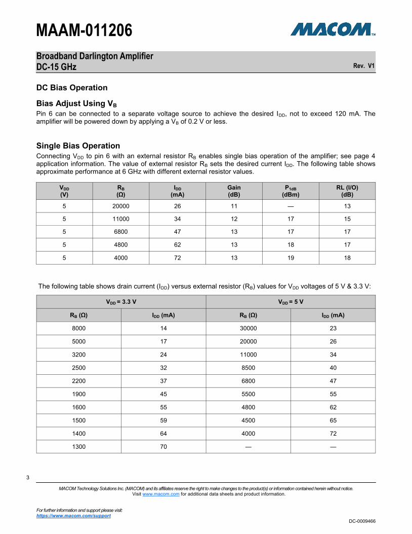
DC Bias Operation
VDD
(V) RB
(Ω) IDD
(mA) Gain (dB)
P1dB
(dBm) RL (I/O)
(dB)
5 20000 26 11 — 13
5 11000 34 12 17 15
5 6800 47 13 17 17
5 4800 62 13 18 17
5 4000 72 13 19 18
Bias Adjust Using VB
Pin 6 can be connected to a separate voltage source to achieve the desired IDD, not to exceed 120 mA. The amplifier will be powered down by applying a VB of 0.2 V or less.
Single Bias Operation
Connecting VDD to pin 6 with an external resistor RB enables single bias operation of the amplifier; see page 4 application information. The value of external resistor RB sets the desired current IDD. The following table shows approximate performance at 6 GHz with different external resistor values.
The following table shows drain current (IDD) versus external resistor (RB) values for VDD voltages of 5 V & 3.3 V:
VDD = 3.3 V VDD = 5 V
RB (Ω) IDD (mA) RB (Ω) IDD (mA)
8000 14 30000 23
5000 17 20000 26
3200 24 11000 34
2500 32 8500 40
2200 37 6800 47
1900 45 5500 55
1600 55 4800 62
1500 59 4500 65
1400 64 4000 72
1300 70 — —
Broadband Darlington Amplifier DC-15 GHz
Rev. V1
MAAM-011206
4 4
MACOM Technology Solutions Inc. (MACOM) and its affiliates reserve the right to make changes to the product(s) or information contained herein without notice. Visit www.macom.com for additional data sheets and product information.
For further information and support please visit: https://www.macom.com/support
DC-0009466
4
Absolute Maximum Ratings6,7
Parameter Absolute Maximum
Input Power 15 dBm
Operating Voltage 7 V
Junction Temperature8,9 +150°C
Operating Temperature -40°C to +85°C
Storage Temperature -65°C to +150°C
6. Exceeding any one or combination of these limits may cause permanent damage to this device.
7. MACOM does not recommend sustained operation near these survivability limits.
8. Operating at nominal conditions with TJ ≤ +150°C will ensure
MTTF >1 x 10⁶ hours.
9. Junction Temperature (TJ) = TC + ӨJC * (V * I)
Typical thermal resistance (ӨJC) = 90°C/W.
a) For TC = +25°C,
TJ = 57°C @ 5 V, 72 mA
b) For TC = +85°C,
TJ = 121°C @ 5 V, 80 mA
Handling Procedures
Please observe the following precautions to avoid damage:
Static Sensitivity
These electronic devices are sensitive to electrostatic discharge (ESD) and can be damaged by static electricity. Proper ESD control techniques should be used when handling these devices.
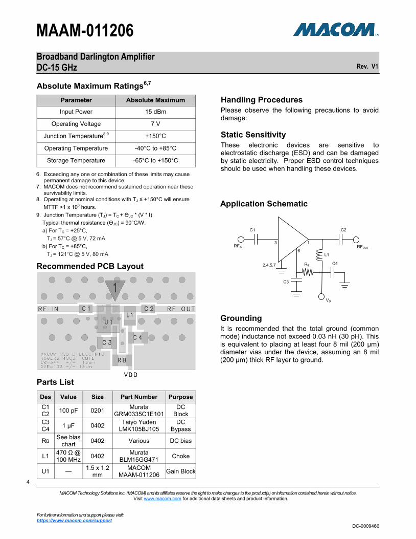
Application Schematic
Recommended PCB Layout
Parts List
Des Value Size Part Number Purpose
C1 C2
100 pF 0201 Murata
GRM0335C1E101 DC
Block
C3 C4
1 µF 0402 Taiyo Yuden
LMK105BJ105 DC
Bypass
RB See bias
chart 0402 Various DC bias
L1 470 Ω @ 100 MHz
0402 Murata
BLM15GG471 Choke
U1 — 1.5 x 1.2
mm MACOM
MAAM-011206 Gain Block
C1 C2
3 1
6
2,4,5,7
C3
C4
L1
RB
RFIN RFOUT
VD
Grounding
It is recommended that the total ground (common mode) inductance not exceed 0.03 nH (30 pH). This is equivalent to placing at least four 8 mil (200 μm) diameter vias under the device, assuming an 8 mil (200 μm) thick RF layer to ground.

Broadband Darlington Amplifier DC-15 GHz
Rev. V1
MAAM-011206
5 5
MACOM Technology Solutions Inc. (MACOM) and its affiliates reserve the right to make changes to the product(s) or information contained herein without notice. Visit www.macom.com for additional data sheets and product information.
For further information and support please visit: https://www.macom.com/support
DC-0009466
5
Typical Performance Curves: TA = 25°C, VDD = +5 V, RB = 4 kΩ, ZO = 50 Ω
P1dB PSAT
OIP3 Noise Figure
Gain Return Loss
0
5
10
15
20
25
30
0 2 4 6 8 10 12 14 16
S21 (
dB
)
Frequency (GHz)
-30
-25
-20
-15
-10
-5
0
0 2 4 6 8 10 12 14 16
S11S22
S11 &
S2
2 (
dB
)Frequency (GHz)
0
5
10
15
20
25
30
0 2 4 6 8 10 12 14 16
P1dB
(dB
m)
Frequency (GHz)
0
5
10
15
20
25
30
0 2 4 6 8 10 12 14 16
PS
AT (
dB
m)
Frequency (GHz)
0
10
20
30
40
0 2 4 6 8 10 12 14 16
OIP
3 (
dB
m)
Frequency (GHz)
0
2
4
6
8
0 2 4 6 8 10 12 14 16
Nois
e F
igure
(dB
)
Frequency (GHz)

Broadband Darlington Amplifier DC-15 GHz
Rev. V1
MAAM-011206
6 6
MACOM Technology Solutions Inc. (MACOM) and its affiliates reserve the right to make changes to the product(s) or information contained herein without notice. Visit www.macom.com for additional data sheets and product information.
For further information and support please visit: https://www.macom.com/support
DC-0009466
6
P1dB vs. Frequency over Temperature P1dB vs. Frequency over Current
OIP3 vs. Frequency over Temperature Current vs. RB (Bias Resistance)
Gain vs. Frequency over Temperature Gain vs. Frequency over Current
Typical Performance Curves: TA = 25°C, VDD = +5 V, RB = 4 kΩ, ZO = 50 Ω
0
5
10
15
20
25
30
0 2 4 6 8 10 12 14 16
+25°C-40°C+85°C
S21 (
dB
)
Frequency (GHz)
0
5
10
15
20
25
30
0 2 4 6 8 10 12 14 16
RB = 4.0 kRB = 6.8 kRB = 11.0 kRB = 20.0 k
S21 (
dB
)Frequency (GHz)
0
5
10
15
20
25
30
0 2 4 6 8 10 12 14 16
+25°C-40°C+85°C
P1dB
(dB
m)
Frequency (GHz)
0
5
10
15
20
25
30
0 2 4 6 8 10 12 14 16
RB = 4.0 kRB = 4.8 kRB = 5.5 kRB = 8.5 k
P1dB
(dB
m)
Frequency (GHz)
0
10
20
30
40
0 2 4 6 8 10 12 14 16
+25°C-40°C+85°C
OIP
3 (
dB
m)
Frequency (GHz)
0
20
40
60
80
1 3 5 7 9 11 13 15
5.0 V
3.3 V
IDD (
mA
)
Bias Resistance(k)

Broadband Darlington Amplifier DC-15 GHz
Rev. V1
MAAM-011206
7 7
MACOM Technology Solutions Inc. (MACOM) and its affiliates reserve the right to make changes to the product(s) or information contained herein without notice. Visit www.macom.com for additional data sheets and product information.
For further information and support please visit: https://www.macom.com/support
DC-0009466
7
Sample PCB Parts List
Des Value Size Part Number Purpose
C1 C2
100 pF 0201 Murata
GRM0335C1E101 DC
Block
C3 C4
1 µF 0402 Taiyo Yuden
LMK105BJ105 DC
Bypass
R2 See bias
chart 0402 Various DC bias
L1 470 Ω @ 100 MHz
0402 Murata
BLM15GG471 Choke
U1 — 1.5 x 1.2
mm MACOM
MAAM-011206 Gain Block
Sample PCB
Gain
Performance Data: Typical performance of sample PCB with VDD = 5 V and R2 = 4 kΩ
Sample PCB Layout
Sample PCB Schematic
Return Loss
0
5
10
15
20
25
30
0 2 4 6 8 10 12 14 16
S2
1 (
dB
)
Frequency (GHz)
-30
-25
-20
-15
-10
-5
0
0 2 4 6 8 10 12 14 16
S11
S22
S1
1 &
S2
2 (
dB
)
Frequency (GHz)
C1 C2
3 1
6
2,4,5,7
C3
C4
L1
R2
RFIN RFOUT
VD

Broadband Darlington Amplifier DC-15 GHz
Rev. V1
MAAM-011206
8 8
MACOM Technology Solutions Inc. (MACOM) and its affiliates reserve the right to make changes to the product(s) or information contained herein without notice. Visit www.macom.com for additional data sheets and product information.
For further information and support please visit: https://www.macom.com/support
DC-0009466
8
† Reference Application Note S2083 for lead-free solder reflow recommendations.
Plating is NiPdAuAg.
Lead-Free 1.5 x 1.2 mm 6-Lead

Broadband Darlington Amplifier DC-15 GHz
Rev. V1
MAAM-011206
9 9
MACOM Technology Solutions Inc. (MACOM) and its affiliates reserve the right to make changes to the product(s) or information contained herein without notice. Visit www.macom.com for additional data sheets and product information.
For further information and support please visit: https://www.macom.com/support
DC-0009466
9
MACOM Technology Solutions Inc. All rights reserved. Information in this document is provided in connection with MACOM Technology Solutions Inc ("MACOM")products. These materials are provided by MACOM as a service to its customers and may be used for informational purposes only. Except as provided in MACOM's Terms and Conditions of Sale for such products or in any separate agreement related to this document, MACOM assumes no liability whatsoever. MACOM assumes no responsibility for errors or omissions in these materials. MACOM may make changes to specifications and product descriptions at any time, without notice. MACOM makes no commitment to update the information and shall have no responsibility whatsoever for conflicts or incompatibilities arising from future changes to its specifications and product descriptions. No license, express or implied, by estoppels or otherwise, to any intellectual property rights is granted by this document. THESE MATERIALS ARE PROVIDED "AS IS" WITHOUT WARRANTY OF ANY KIND, EITHER EXPRESS OR IMPLIED, RELATING TO SALE AND/OR USE OF MACOM PRODUCTS INCLUDING LIABILITY OR WARRANTIES RELATING TO FITNESS FOR A PARTICULAR PURPOSE, CONSEQUENTIAL OR INCIDENTAL DAMAGES, MERCHANTABILITY, OR INFRINGEMENT OF ANY PATENT, COPYRIGHT OR OTHER INTELLECTUAL PROPERTY RIGHT. MACOM FURTHER DOES NOT WARRANT THE ACCURACY OR COMPLETENESS OF THE INFORMATION, TEXT, GRAPHICS OR OTHER ITEMS CONTAINED WITHIN THESE MATERIALS. MACOM SHALL NOT BE LIABLE FOR ANY SPECIAL, INDIRECT, INCIDENTAL, OR CONSEQUENTIAL DAMAGES, INCLUDING WITHOUT LIMITATION, LOST REVENUES OR LOST PROFITS, WHICH MAY RESULT FROM THE USE OF THESE MATERIALS. MACOM products are not intended for use in medical, lifesaving or life sustaining applications. MACOM customers using or selling MACOM products for use in such applications do so at their own risk and agree to fully indemnify MACOM for any damages resulting from such improper use or sale.