sagvd aas qsaiui2u!pu11s1no saao.id iavads tao 9 piref7 · "uninterrupted reader interes every...
TRANSCRIPT

(
9 piref7 sagvd aas qsaiUI2u!pu11s1no saAo.id iavads Tao augidaw
olvcro 5 1.N id
,7Aez eAry
NOI1VSN3S S3A01Id 113)1V3dS 111013 aNVIdUIV
sigoid 2Ki uivasaapung las tuoisn3
puourewl 0-s agni-9
saapvoN Joj pazAteuyacini ppD maias
;uG3 SI
Strom awrell puonutsi APO Pug lsiU

RADIO WORLD March 3, 1928Another ENSCO Scoop
ENSCO PIANO UNITmakes a marvelous Loud Speaker of your Piano. You will be astounded at the superb tone quality your pianois capable of delivering. Superior to anything you ever heard. And why not? There is no better reproducingmedium than the seasoned wood, sound board of your piano. Are not the most important musical instruments-the violin, 'cello and piano-made of wood?
The Ensco Piano Unitallows you to take ad-vantage of this most per-fect of reproducing medi-ums. You attach it intwo minutes-no fuss, noextra equipment, anyradio set, any piano.Does not show and does'not mar or interfere withpiano.
On demonstration at all ENSCOpayable to Engineers Service Co.
Main Office:25 Church Street
New York City
Studios. Mail and telegraphOrder at once from nearest
orders filled.office.
The sensation of the dayin radio.
ONLY
$ 1 010 -Day Money -Back
GuaranteeComplete with 20 footcord. It is the idealloudspeaker. You do notneed to know music torealize this fact. Hearit-try it-and be con-vinced.
Make checks and money -orders
ENGINEERS' SERVICE COMPANY28 E. Jackson Blvd., Chicago, Ill. 331 Bay Street
Toronto, Canada
Allow us to introduce to you the-VOLUME CONTROL
CLAROSTATThe baby member of the Ciarostat family, but a hogfor work. This micrometric resistance is intendedfor controlling loud -speaker volume and tone, platevoltage, oscillation, regeneration, stabilization, andother functions in the radio receiver. Resistancerange of practically zero -500,000 ohms, covered inseveral turns of knob, thus providing true micro-metric resistance. Holds its adjustments. Staysput. Silent in operation. Fool -proof. Ample cur-rent -handling capacity for receiving requirements.All of which is yours for 01.50.
Ask your dealer to show you theClarastat line and give you ourpractical data on how to improveyour radio. Or write us direct.
American Mechanical Laboratories, Inc.NIEMaect Specialists in Variable Resistors
285-87 North 6th StreetBrooklyn, N. Y. .
Guaranteed "A" Power Unit-$13.75No better "A" Socket Power Unit can be obtained
even at twice this amazingly low price. No hum ornoise. Operates on 50 or .60 cycles. at 110 volts A.C.Approved by rigid laboratory tests of Radio News andPopular Radio. Fully guaranteed. Shipped complete,subject to inspection, on receipt of price --orif you wish. 5% discount if cash in full is sent withorder. Send order NOW! WORLD BATTERY CO.,1219 South Wabash Ave., Dept. 64, Chicago, Ili.
Subscribers : Look at theExpiration Date on
Your WrapperWe do not like to take your name from
our subscription list without specific in-struction to do so, because many of ourreaders wish to keep a complete file of thepaper.
Please therefore, look at the subscriptiondate stamped on your last wrapper, andif that date is earlier than the issue con-tained in the wrapper, please send checkto cover your renewal.
In this way you will get your copieswithout interruption.
Subscription Dept, RADIO WORLD, 145 W.45th Street, New York City.
Professional Set BuildersCan secure the 28" x 34", two-color, X -RayMagnaformer 9-8 Wiring Diagram by sending25c to Radia' rt Laboratories Co., 19 S. La SalleSt., Dept. 6, Chicago, Ill.
Name
U. S. PatentNo. 1,564,654
You Need
"Vac -Shields"for the New 222Shield Grid Tubeto Stabilize Your
SetTHE invention of
these non-magneticshields for Type 201-Aor the new Type 222Tubes prevents inter -
stage coupling andelectro - static effects,overcoming stray ca-pacities that maketuning of distant sta-tions so difficult.Attached in a minute.Order today by mail,
C. 0. D., $1.00.
ORANGE RESEARCH LABORATORIES247-249 McKinley Avenue
East Orange, N. J.
$100 WILL SAVE YOURSPEAKER
The Craftsman DollarSpeaker Filter is Guaran-teed to relieve your speakerof the DC plate current(up to 250 volts). It givesspeaker a chance to oper-ate at its best. Attachedin a second. Send dollarhill NOW!
CRAFTSMAN RADIO PRODUCTS9 Orchard St. Newark, N. J.
FROST -RADIOExclusively Specified for
Shield Grid Diamond
Described in This IssueHERBERT H. FROST, Inc.
Main Offices and Factory:ELKHART, IND.New York Chicago^ ^
HERBERT H. FROST, Inc.,160 N. LaSalle St., Chicago.
Mail me a copy of your free book, "What SetShall I Build?"
Name
Address
CityState
FORTY TIMESas Much Amplification!
The New Shielded Grid
4 -TUBEDIAMOND
OF THE AIRDesigned by FL B. HERMAN
and described by him in the February 411 and 18 issues of RADIO WORLD.
The favorite four -tube design, simple ascan be, takes a great step forward, sothat home constructors of radio receivers,and custom set builders, can build a dis-tance -getting and voluminous set, the partsfor which list remarkably low.
The new shielded grid tube is used asthe radio frequency amplifier. That iswhy the amplification is boosted fortytimes over and above what it would beif an -0IA tube were used instead.
Such simplicity of construction marksthe receiver that it can be completelywired, skillfully and painstakingly, in twoand a half hours.
All you have to do is to follow the of-ficial blueprint, and lol a new world ofradio achievement is before you! Distantstations that four -tube sets otherwise misscome in, and come in strong. No tuningdifficulty is occasioned by the introductionof this new, extra powerful, startling tube,but, in fact, the tuning is simplified, be-cause the signal strength is so muchgreater.
When you work from the official wiringdiagram you find everything so delight-fully simple that you marvel at the speedat which you get the entire receiver mas-terfully finished. And then when you tunein-more marvels! 'Way, 'way up, some-where around the clouds, instead of onlyroof high, will you find the amplification IYou'll be overjoyed. But you shouldplace every part in exactly the rightposition. Stick to the constants given, and,above all, wire according to the blueprint!
Front Panel, Subpanel andWiring Clearly Shown
When you work from this blueprint youfind that every part is shown in correctposition and every wire is shown goingto its correct destination by the ACTUALROUTE taken in the practical wiring it-self. Mr. Herman's personal set was usedas the model. This is a matter-of-faotblueprint, with solid black lines showingwiring that is above the aubpanel, anddotted lines that show how some of thewiring is done underneath.Everything is actual size.Not only is the actual size of the panelholes and instruments given, but the dimen-sions are given numerically. Besides, itis one of those delightful blueprints thatnovice and professional admire so much-one of those oh -so -clear and can't -go -wrongblueprints.Be one of the first to send for this newblueprint, by all means, and build yourselfthis outstanding four -tube receiver, withits easy control, fine volume, tone quality,selectivity and utter economy. It givesmore than you ever expected you couldget on four tubes-and the parts are wellwithin the range of anybody's purse.The circuit consists of a stage of tunedRF shielded grid tube amplification, aregenerative detector, and two transformercoupled audio stages.What a receiver!
$1.00 for 27" x 27" Blueprint,15c extra for Feb. 4 issue.
Send your order today!
RADIO WORLD,145 West 45th St., N. Y. City.Enclosed please find:
S1.00, for which send me at once one of-ficial blueprint of the Four -Tube Shielded GridDiamond of the Air, as designed by H. B. Ber-man, and described by him in the February 4,11 and 18 issues of Radio World.45 cents exile. for Feb. 4th, 11th, 18th issues.
Address NAME
ADDRESSCITY STATE

"UNINTERRUPTED READER INTERESEVERY WEEK L--.) EVERY YEAR
Vol. XII. No. 24. Whole No. 310MARCH 3, 1928
15c per Copy. $6.00 per Year[Entered as second-class matter, March,1922, at the post office at New York, N. Y.,
under Act of March, 1879)
RADIO WORLD
Technical Accuracy Second to None A Weekly Paper Published by HennessyRadio Publications Corporation, fromPublication Offi'ce 145 West 45th Street,
New York, N. Y.
Phones: BRYant 0558 and 0559
New -50 Power Tube Takes8A
4._ egative Grid Volts!wERE vacuum tubes endowed with
consciousness and were they subjectto jealousy, they would all be emitting agreen glow of hatred at this time.
A new king of power tubes has risen.And what is this new king? It is the
new -50 power tube, the latest additionto the radio "balance of power."
The characteristic table follows:
By Chisholm W. Parker
required filament terminal voltage is thesame. Thus the new tube can be used inany circuit designed for a -10 power,except that 'the coupling coil in the platecircuit must be able to stand a far greaterload.
Current Question SeriousThe new tube's physical dimensions are
Recommended Maximum
Plate voltage 250 300 350 400 450 voltsNegative grid bias 45 54 63 70 84 voltsPlate current 28 35 45 55 $5 m. a.
Plate AC resistance 2100 2000 1900 1800 1800 ohmsmicro -
Mutual conductance 1800 1900 2000 2100 2100 mhosVoltage gain factor 3.8 3.8 3.8 3.8 3.8
milli -
Max. Undistorted output 900 1500 2350 3250 4650 watts
Filament: 7.5 volts, 1.25 amperes (oxide coated).Max. overall: height 6'4 inches, diameter 2 11/16 inches.Base, large standard push type (X)Rating: as amplifier, max. 4.65 watts; oscillator, 25 watts.
In looking over this table of normalcharacteristics one is struck by the manysimilarities between this tube and the -71.In fact it sems like the -50 is an over-grown -71. The amplification constantof the new tube is 3.8 while that of the-71 is 3. The internal plate AC resistanceof each is about 2,000 ohms for the recom-mended grid and plate voltages. Themutual conductance of the -50 is con-siderably greater than that of the -71,indicating that the new tube is a superiorpower amplifier.
Where Similarity EndsWhen the -50 and the -71 tubes are
compared with respect to power handlingcapacity the similarity ceases. The newtube is in a class by itself. With 450 volts(maximum) on the plate of the -50 tubethe maximum undistorted output is 4,650milliwatts while that of the -71 with 180volts (maximum) on the plate is only 700milliwatts. Thus the maximum output ofthe new tube is about 6.6 times as greatas the maximum output of the other.
Of course, a much higher voltage is re-quired on the plate of the -50 than onthe plate of the -71.
While the new tube has been comparedwith the -71, it was really developed toreplace the -10 power tube, and there-fore the new tube should be comparedwith that also.
We find that the -50 takes the samefilament current as the -10 and that the
slightly larger, but in few cases will thesubstitution be frustrated for lack ofroom.
The recommended and the maximumplate voltages are about the same for boththe -50 and the -10 tubes. Thereforeplate voltage supply units developed forthe -10 power tube can also be used forthe -50 tube as far as voltage goes, butsome of them may not be able to deliver the necessary plate current and maintaina high voltage.
The first thing that one should ascertainin this respect is whether the plate chokecoil or the primary of the output trans-former will carry all the current neces-sary. The carrying capacity has to bemore than double the current carrying ca-pacity of a coil or transformer designed -for either a -71 or a -10 power tube.Few coils now available will carry enoughcurrent to supply one of the new tubes,but more will appear soon. The currentrequired for the higher plate voltages is55 milliamperes, almost enough to heatthe filament of a -99 type tube.
The maximum undistorted power out-put of the -10 tube with 425 volts on theplate is 1,540 milliwatts and the corres-ponding output of the -50 tube with 450volts on the plate is 4,650. That favorsthe new tube in the ratio of 3 to 1. Thusfor a given output power the distortion inthe -50 will be about 1/9 as great as thatin the output of the -10 tube, assuming
that the input to the -50 is as pure asthat to the -10 tube.
The low amplification constant of the-50 tube retires that the' input voltagebe much higl- er than that for the -10tube for equa output. Hence there is agreater chat -16e for distortion to creep intothe signal in the stages preceding thepower tube. But in this respect the -50is much superior to the -71 tube.
Also because of its low amplificationconstant the required grid bias on the-50 tube must be high for given platevoltages. Thus when the plate voltage is250 the negative grid bias should be 45volts, and when the plate voltage is '450the required grid bias should be 84 volts.
The grid bias can be obtained in anyone of several ways. The two most com-mon are the dry cell battery method andthe drop -in -resistance method. Theformer is electrically the better in allcases but it may be objectionable on theground of space requirements. This is ac-centuated in the case of the -50 tube.The negative grid bias at 450 plate voltsis almost as high as the last tube platevoltages common two years ago.
The Stage AheadIf a resistor is used and the plate cur-
rent from a single -50 tube flows throughthat. resistor, then the value of the re-sistance should be about 1,500 ohms. Thisis also the resistance required for a -10tube so that no change is necessary whensubstituting tubes, provided that the re-sistance already in the circuit can carry55 milliamperes. Somewhat lower valuesof resistance may also be used, especiallywhen the lower plate voltages are used.The 1500 ohm value was based on a platevoltage of 450 volts.
When this tube is used it is necessaryto make sure that the tube preceding it isable to handle all the AC voltage requiredwithout distortion. It has hardly everbeen necessary to raise this point in con-nection with previous power tubes.
Since the plate current in the new tubemay be as high as 55 milliamperes it isobvious that no present loudspeaker canbe connected directly into the plate circuitwithout burning it out. A coupling de-vice is necessary, and this may be eithera transformer or a choke and condenserfilter.
The tube is suitable for reproduction inhalls, clubs, auditoriums, theatres, and ininstitutions having dozens of telephone re-ceivers. Home conditions hardly requireits use.

4 RADIO WORLD March 3, 1928
An Airplane ClothNOT since the highly developed cone
forced the old-fashioned horn out ofthe throne of popular favor has a parlorspeaker appeared that for modest outlayoffers such advanced performance as thebox type speaker made with airplane clothdiaphragm.
The speaker looks like a b'ox kite, andindeed it could be used as such, particular-ly as it is so generously equipped with ahigh -flying diaphragm-an airplane clothsurface 18 by 24 inches.
Wings, and sometimes fuselage, of air-planes are made of this material. Indeed,the Spirit of St. Louis itself was soequipped when Col. Charles A. Lindberghflew that famous craft alone across theAtlantic, and, more recently, on a good-will trip to South America.
So you may well imagine that airplanecloth, to withstand such use, is durable.Also it is light. Moreover, it is not ex-pensive. But not its durability, its econ-omy or its lightness constitutes its out-standing asset for the chief purpose wehave in mind. Rather, its performancewhen used as the sounding "board" of areproducer.
And when we investigate that, we findit is the most intriguing medium of all.
Stretch It TightPurity of tone, clarity beyond one's pre-
vious experience, almost take our breathaway, for we had passed through sevenyears of radio reception without enjoyingthe eye-opening realism made possible bythis sensational speaker.
Indeed, one must dip into past experi-ence to bring forth the new airplane clothspeaker, the HBH model of which is il-lustrated herewith.
One takes standard airplane cloth, ofbest quality, and stretches it upon a rect-angular wooden frame, on the back ofwhich is a small square of the same cloth,so that as the centers of the two piecesare drawn tightly together and sealed bythe two meeting apexes, the necessarystrong tension upon the large diaphragmthus being assured.
The old principle of using two dia-phragms is not invoked, since modernengineering practice has discovered loop-holes aplenty in the theory that a largerdiaphragm responds to the low notes anda smaller one to the high notes, so thatthe combination gives almost ideal repro-duction. Indeed, the two -diaphragm mightwell give ideally miserable results, withtwo strong resonance peaks, one high, onelow, to torment the listener with boomingand trilling that persist after the originalnotes have ceased.
ewVistaHow a Kite Model Rep:with a Rich, Clear, Pure
FIG. 1FRONT VIEW OF THEHBH AIRPLANE CLOTHSPEAKER THAT REPRO-DUCES WITH SUCHAMAZING PURITY ANDCLARITY OF TONE THATIT HAS BEEN HAILED AS
A SENSATION
No, it is not, in any double diaphragmthat the airplane cloth speaker gets itsplenitude of virtues, but in the tautnessto which the treated light, responsive clothis stretched. It is assumed a good unitis used, and of course it must be of thepin or stylus type, with the rod stickingout so that it will move the speaker dia-phragm.
Builder Treats ClothTreatment of the cloth by painting or
spraying it with a special preparation givesthe stiffness required for reproductionpurposes. When the tautness is suppliedby flexing the tension of the larger oblongspan against the smaller square one, youhave a speaker that will give you lownotes that you have never heard before,and also will afford excellent reproductionon the highest notes.
The frequency characteristic, while notflat, is wider in effective range than al-most anything you have ever heard, andcertainly surpasses anything else that canbevurchased or assembled for a few dol-lars. Real quality at next to no costis what you get, and you acquire a speakerthat not only fills you with pride and de-light as you listen to its marvelous work,
Elliptical Dead Spotiscovered In Speaker
One of the peculiar facts concerning theAirplane Cloth Speaker is that, when con-structed with the diaphragm pulled in bythe tension of the small sheet, there is anelliptical part of the surface, about six`inches from the center, where the diaphragmhardly vibrates at all.
For instance, at the center, just around theapex, the vibration is strong, 'and it continuesto be so for several inches, when there is agradual reactive decline. Then suddenlycomes the round area where there is nextto no vibration. Progressing toward theframe, one finds great activity again.
The tightening of the diaphragm, by
stretching it almost as much as possiblewith the unaided hands, causes stress tobe exerted principally on that part of thecloth where the bend toward the center be-gins. The pull is inward, while the edgesof the speaker tend to' resist this pull. Hencewhere the pull begins to converge into theresistance, or where the opposite forcesmeet, a form of acoustical neutralization setsin.
This you can verify by passing your fin-gers about the cloth when the speaker isoperating.
When you feel next to no vibration.youwill know you've "hit the spot."
By H.
but which wins the praise of all guestsprivile,ged to hear your set work thisspeaker in your home.
A great deal of engineering thought hasbeen centered on proper reproduction oflow notes, and the point soon was reachedwhere receivers were better able to' dojustice to low notes than were the gener-ally available commercial speakers. Suchis the case even now. Audio transformersamplify low notes and have relatively evenamplification throughout the scale of use-ful frequencies. Other forms of amplifica-tion do as well or better, but speakershave curves that look much like the teethof a bucksaw.
At the lower end of the audible fre-quency spectrum the response is veryfeeble.
Lo, the Low NotesWith a properly constructed airplane
cloth speaker the low notes get a moresympathetic reaction than do the highnotes, so that the slight unbalance existingin reproduction, due to the receiver char-acteristics, so justly composed for, andamazing reproduction is obtained evendown to 30 cycles, which is about thelower limit of audio frequency modulatedby broadcasting stations.
You can hear the tuba on the airplanecloth reproducer so that it has individual-ity, character and force all its own, sincethe fundamental brings forth active re-sponse from this newly adopted diaphragmwhereas under normal conditions you de-pend on a distorted harmonic of that lowfundamental note for any response youmight get .from the speaker.
The organ sounds just as an organshould sound, and if the transmission isdown to 16 cycles, the minimum of theorgan, and if your receiver can handlethis extremely low frequency, you canrely on a properly constructed airplanecloth speaker of the kite type to pick upthe note and toss it to you in as delightfula fashion as one's fondest expectationscould concoct. The bass viol stands out,too, as do all the other low-note instru-ments. Since the faithful reproductionof low ,notes gives character and life tomusic, you get an absolutely new and su-perior form of enjoyment from listeningto such a speaker.
Some Fundamental TestsIf you flick the taut diaphragm with
your finger you will hear a response muchlike what you get from a drum. Ittherefore follows that the bass drum andthe kettle drum beat their enspirited tat-too upon your eager ears, and make you'fidget with keen delight in your listener'schair.If you will build yourself such a speak-
er and, holding it at the top, let the bot-tom board of the frame strike the floor,
Acom

March 3, 1928 RADIO WORLD 5
Speaker That Opensof Delight
ucer Brings Out NotesGne That Astonishes Allitierman1...xpert
you will hear a sound somewhere around150 cycles, and this is approximately thenatural period of the speaker, providedthe diaphragm is stiff and, taut.
But if the diaphragm is loose, or with-out being loose is still not tight enough,there will be an acute resonant peak thatwill boom forth unpleasantly as the after-math of any note struck at about the fun-damental frequency; also the qualitythroughout the scale will b'e thin and life-less. The reason is that the airplane clothis more useful for reproduction purposesthe greater the tension and stiffness-andit easily acquires both of these, while stillretaining lightness, thus making the mostacceptable combination.
The Four StepsThe speaker is so easy to make that al-
most anybody can complete the entireconstruction in an hour and a half, andthat includes every piece Of work andpresupposes a leisurely and painstakingmanner of construction. There are fouressential moves :
(1) Construction of the frame.(2) Placement of the crossarms.(3) Placement, stiffening and tautening
of the big diaphragm and the small squaretension guard.
(4) Mounting the unit.Each operation is as simple as possible,
there is next to no possibility of failure,if the stated precautions are taken, andthe result is that for a few dollars youget as fine a quality reproducer as youwould want. And after you've listenedto it delightedly you may decide to drapeit with brocade, chintzes or the like, sothat it may occupy a niche of importanceon the moulding of your parlor, or adorna marble table or, indeed, squat on theChinese rug that graces your most tastilyappointed room.
How to AssembleThe outside frame is assembled as
shown by Fig. 1. The cloth is then cut ofsufficient size to cover the front, stretchedon and tacked.
The manner of stretching is very im-portant and is as follows:
Place the cloth on the frame and tackat the center of the left-hand side. Nowtake hold of the cloth at the lower left-hand corner of the frame, stretch downtightly toward the left-hand corner andtack. Fill in between with tacks aboutone-half inch apart.
With the right hand take hold of thecloth at the center on the right-hand sideof the frame, stretch across tightly andtack down. Then take hold of the clothat the upper right-hand corner and pullupward tightly and tack. About one-halfinch apart place tacks in between. Younow have the main stretching done.
It doesn't matter just where you takehold of the cloth now, but stretch on
FIG. 2THE REAR VIEW SHOWSTHE CROSS -ARMS, TEN-SION GUARD (THE SMALLSQUARE), BRACKET ANDUNIT. THE PIN IS ONTHE OTHER SIDE OF THEUNIT, POINTING AWAY
FROM YOU.
tightly all around and fill in, always re-membering that the tighter you stretchthe better your speaker will be.
Now assemble the rear frame. Take thetwo long narrow wooden pieces andmeasure out the center point on each.Measure off 3 inches on each side of thecenter of both of these. Now place thetwo short narrow wooden pieces betweenthese long ones so that the inside of thesmall pieces is six inches apart, forming asquare six inches large. Nail together inthis position, using only one nail for eachjoint.
The Rear PieceThe small rear cloth or tension guard is
then cut and tacked on in the same man-ner as the large one.
DON'T PLACE THIS SMALLFRAME INSIDE THE LARGE ONEYET.
You are now ready to insert the apex,consisting of two pieces, one for thecenter of each cloth.
The center of each cloth is found bylaying a yard stick across the diagonalcorners and drawing light lines near thecenter. Where these lines meet is thecenter. Pierce a small hole at the centerin each cloth.
NOW place the large frame face down
on a table and the small one face up in-side the large one, with the centers overeach other. The apex is now inserted,one plate on the outside of each cloth, andboth pointing toward each other. Thecenter of the apex is inserted with theadjustable part on the front.
Feller Needs a FriendNow you need the help of a friend. Ask
your friend to stand on each side of thespeaker and take hold of the two legs ofthe small frame, one leg in each hand.You do the same on the other side. Nowboth of you pull up slowly, stretching thecloth until the small frame is flush withthe edge of the large frame. You nowhave to let one leg go, to nail the otherone up. The one you let go will drop alittle, of course, but after you sink thefirst nail you can draw up the leg andfinish nailing it.
All FinishedNow go over to your friend's side and
nail up that side. This causes the twocloths to converge.
Now apply two coats of the special stif-fening fluid, allowing each coat to dryfor twenty minutes. The bracket is nowassembled to the unit (Fig. 2). Screw thebracket to t ie frame as shown. Firstput the pin of the unit inside of the apex.Tighten the apex.
The moulding is . now placed on thefront of the speaker, over the tacks.The speaker may be painted any desiredcolor, or may be otherwise decorated.
[Follow the articles in RADIO Wont,from week to week on the new and fascinat-ing Airplane Cloth Speaker.]
Still Picture ReceiverUnder Way by R. C. A.
A commercial form of radio still picturereceiver for sale to home users is beingdeveloped by the Radio Corporation ofAmerica group of manufacturers, accord-ing to Dr. A. N. Goldsmith, chief broad-cast engineer of America.
Two types of receiver are contemplated,one which combines visual and aural re-ception and one which can be plugged intoany good radio receiver to convert thatto a picture receiver..
The first public demonstration of thesystem was made on Jan. 27 when thephotograph of Mayor James J. Walkerof New York was transmitted over WEAFand received by Dr. Goldsmith in his homein New York. The transmission of Mr.Walker's photograph required ninety sec-onds.
Sensitive ReproducerCoupled Through Air
The usual practice in cone speaker con-struction is to have the diaphragm point out-ward, that is, toward the point of the pin orstylus of the unit. But in the Airplane ClothSpeaker the real sounding board, that is, thelarge surface, points inward, and, inciden-tally, so does the small cloth guard.
In effect, the large surface takes up mostof the vibration, in fact, nearly, ten times asmuch as the smaller one. The pull and thearmature is almost exclusively by the largesurface, since the smaller one serves as abrace, and the fact the smaller guard takes
up vibration is purely incidental and unavoid-able.
Indeed, were another speaker of the sametype as the airplane cloth model placed evena few feet away, while the first speaker wasacutated by the output of a receiver, the sec-ond speaker would send forth reproductionon its own account, having taken up vibra-tion from the first one. This is acousticalcoupling and is of about the same order ofnon -intensity when the distance of the two isone foot as is the coupling between the largediaphragm and the small tension guard.

6 RADIO WORLD. March 3, 1928
A SIDE VIEW OF THE FIVE TUBEAIR. THE EXTRA TUBE ADDS NO
VARIABLE OF ANY SORT TO
AFIFTH tube may be added to theFour Tube Shielded Grid Diamond of
the Air, if subpanel dimensional instruc-tions given in the February 4 and 11 is-sues of Radio World were followed.
The subpanel, if 10 inches deep, with allparts placed according to the blue -printpattern, permits of the addition of a stageof tuned radio frequency amplificationbetween the first RN' tube aim the de-tector.
You do not have to alter the front panelin any way. In fact, the total work con-cerns these additions: fifth socket behindthe tickler coil; third tuning condenserin tandem with the second tuning con-denser, by using one shaft runningthrough both ; a coil, just like the antennacoil, placed at right of the ganged con-densers; a No. 622 Amperite with mount-ing, placed near the new socket.
The wiring is changed only so far asconnecting to these parts.
The added tube may be a shield gridtube, so that you have two stages gridRF amplification, regenerative detectorand two stages of transformer coupledaudio-a five tube set of remarkable sensi-tivity and selectivity. The same tone ispreserved.
Volume Control Option
The volume Control, R4, is left in thesame position on the front panel, but as atendency toward self -oscillation may arisein the first tube when the fifth tube isadded, it is optional to connect the volumecontrol in series with the first RF B pluslead, as diagrammed ; or you may leave
How to Addto the Shield
By Keith
SHIELDED GRID DIAMOND OF THETUNING CONTROL OR ANY OTHERTHE FRONT PANEL DEVICES.
it across the secondary of the first audiotransformer.
The fifth tube, utilized as described anddiagrammed, adds about 500 miles to thereceiving range.
There are a few pointers on installationthat should be watched carefully.
The main one concerns the ganging ofthe Karas condensers.
This is done by mounting the new con-denser right back of the detector tuningcondenser, but securing the new one tothe subpanel. The existing tuning con-denser, attached by single hole mountingto the front panel, is thus kept firmly inplace, and probably has not been boltedto the subpanel.
The condenser frame, at bottom, hasholes that easily pass 6/32 screws. Thehalf -inch length type is plenty longenough. Use two on the new condenser,but be sure to find the drill hole locationswith strict accuracy, otherwise the twocondensers will not team up properly.
How to Rectify Mistake
If you drill a hole in the wrong placeyou are up against it, for the hole willnot permit of a new one right next toit, in fact half including it, since the drillwill slip into the existing aperture. Prob-ably as good a remedy as any under thecircumstances would be to drill the er-roneous hole sufficiently oversize to passthe screw properly, and tighten a largehex nut against the underneath plans ofthe subpanel to get the proper "bite."
Should the condensers not be in align-ment there will be torque on the common
LIST OF PARTSVital Kit
LIL2, L3L4L5-Hammarlund HR 23, con-sisting of one antenna coupler and onethree -circuit coil, both for .0005 mfd.tuning.
LLo-One Hammarlund RF transformer,same as antenna coil above.
Cl, C4-Three Karas .0005 mfd. SFL con-densers, type 23.
AF1, AF2-Two Karas Harmonik audiofrequency transformers.
R, R1-Two No. 622 Amperites withmountings.
R3, R5, R6-Three No. lA Amperites withthree mountings.R2-One Lynch 5 meg. grid leak.R4-One Volume Control Clarostat.C2, C5, C7-Three Aerovox .006 mfd.
fixed mica condensers.C3-One Aerovox .60025 mfd. mica grid
condenser, with clips.C6-One .001 mfd. Aerovox mica fixed
condenser.S-One Yaxley No. 10 battery switch.PL-One Yaxley No. 310 pilot light brack-et (with lamp extra).PJ-Two Frost phone tip jacks, No. 253.Five Frost Bakelite sockets, No. 530.One 51/2" shaft, 'A" diameter.Two Eby binding posts (Ant., Gnd.).One 7 x 21 inch front panel.One 10 x 20 inch subpanel or baseboard.Two Mar -co dials.Two Pee -Wee clips (No. 45 Universal
clips).Set of three Karas subpanel brackets.
ACCESSORIESTwo shielded grid tubes, Ce Co RF22, for
sockets 1 and 5.Two Vac -Shields for shielded grid tubes.One Q. R. S. 200A detector tube or CeCa
type H, for socket No. 2.One CeCo type A for socket No. 3.One CeCo type F (112) for socket No. 4.One roll flexible Acme Celatsite.One 7 -lead Acme battery cable.One set of cable markers.A, B and C supplies.
shaft. This would bend a metal shaft.A hard rubber or Bakelite shaft will takeup a little torque nicely. If a brass orother metal shaft is used the most ex-treme care must be taken to get the con-denser mounting holes precisely right.
Separate Grid ReturnIt is therefore preferably to use Bake-lite or hard rubber shafting, 51A incheslong. That also affords complete insula-tion between rotors of the teamed con-densers.Naturally, when mounting the secondcondenser you will not permit the frontpart of its frame or the bushing thereon
to touch the corresponding part of theback of the existing condenser. But ifmetal shafting is used, this precaution isuseless.The advantage of the insulated shaft isthat it permits the detector grid return tobe made to negative F for the special de-

March 3, 1928 RADIO WORLD 7
Fifth Tuberid Diamond
Lauderdale
CAP ON TOP OF -22 TUBE/- CAP ON TOP OF -22 TUBE
C6
I
pc
AP/ O ,IlF2
" "
000000
0PJ
0
> PWk.
0 If* AMP0 St oEr:0
$ 0 C- 341) 0 9 + 8-
0- a -
THOSE WHO HAVE BUILT THE FOUR TUBE SH IELDED GRID DIAMOND OF THE AIR AND WHO DE-SIRE TO ADD A FIFTH TUBE, SO AS TO INCREASE THE RECEPTION RANGE ABOUT 500 MILES, MAY DO SOBY MAKING THE FIFTH TUBE THE SECOND RADIO FREQUENCY AMPLIFIER. THIS IS SHOWN ABOVE AS A
SCREEN GRID TUBE. (5) THE CHANGE IS EASILY MADE.
tector tubes, while the RF tube's grid isreturned to minus A. Therefore the RFtube gets a free bias equal to the voltagedrop in R, or 2.7 vols (6 minus 3.3). With135 volts on the plate of the RF tube, oreven a little less, this is a suitable bias,and heightens the selectivity.
Of course, with separate grid returnsmade possible, the detector may be re-turned to F+ for any tube, includingQ. R. S. 200-A or other special detector.Sometimes signals are made louder.
Should a metal shaft be used a differentconnection for the grid leak would haveto be made. Instead of the clips on thegrid condenser being utilized for leakmounting, a special mount must be pro-vided, and it is connected from the G postof the detector socket to the F minus(or F plus) post of the same socket.Then the leak is mounted in the newholder.
System ExcellentThe system of ganging the Karas con-
densers works out excellently, especially
CAP O/Y TDP OF -22 _TUBE
0e1p CI
,L30A.a-posr C
olvsoc ire?'.#
since the tickler of the Hammarlund coilhas a sufficiently high inductive effectupon the adjoining secondary to affordcompensation, if such is necessary. Inmost cases the simultaneous tuning ofthese similar stages with a single motionworks out with splendid balance, requiringno trimmers.
The best way to include the fifth tubeis to get the blue -print of the Four TubeShielded Grid Diamond, lay out all theparts as shown thereon and add thosepreviously mentioned in this article. (Thelist of parts includes all save the extramounting for grid leak if -a metal shaftis used.) Connect up the filament wiring,then wire the new stage first and con-tinue from the blueprint with the rest.Visually it turns out to be very simple,although words may make it seem harderthan it is.
Build the Four FirstHow to incorporate a fifth tube is de-
scribed here solely for the benefit of thosewho have already built the Four Tube S -G
NNWNMI
C6
Diamond. The changes are so few and sosimple that any one starting anew shouldstill build the four tube model first, andmake the change later if he desires.
So extraordinary is the performance ofthe four tube model that many will notcare much about making the addition. Yetthe fellow who hungers for that extra 500miles, which may bring him Denver fromNew York regularly, instead of only Chi-cago through locals, may set his hearton that fifth or specially DX tube.
Still another option presents itself. Ifyou desire to use three shield grid tubesyou may use the third one as the detector.Change over to a 622 Amperite here, also.Connect the cap of the shield grid tubeto B plus 22 to 67, and use resistancecoupling in the first audio stage. Fol-lowed by a Karas transformer, this givessufficient volume.
The incorporation of a shield grid tubeas a space charge detector was fully de-scribed, for the first time anywhere, in theFebruary 18 issue.
R1 F2.
R
oPJ
0
I.%
../.1
eN
.8+ P'Wk,
e+ AMP!
84- DErC- FtWit
> 00000 C-3
o^o-0 A # B-O /4-
THE FOUR TUBE MODEL. WHEN THE FIFTH T UBE IS ADDED IT IS PLACED ELECTRICALLY JUSTAHEAD OF THE DETECTOR. THE VOLUME CONTROL CLAROSTAT IS PUT IN THE B+ AMP. LEAD AT THE
ANGLE OF THAT LINE JUST BELOW WHERE C2 JOINS IT.

8 RADIO WORLD March 3, 1928
The ScreenAnalyzed forEp
Esa
( )
F Go
542 Po .560
(3 )
(C)FIG. 1
A CURVE SHOWING THE CHANGE IN POTENTIAL (ELECTRICAL ALTI-TUDE) BETWEEN THE FILAMENT AND THE PLATE IN AN ORDINARY
VACUUM TUBE.
CURVE SHOWING THE CHANGE IN POTENTIAL BETWEEN THE FILAMENTAND THE PLATE WHEN THE INNER GRID IN A SCREEN GRID TUBE IS
GIVEN A POSITIVE POTENTIAL.THIS CURVE SHOWS THE POTENTIAL DISTRIBUTION BETWEEN THEFILAMENT AND THE PLATE IN A SCREEN GRID TUBE WHEN THE OUTER
GRID IS GIVEN A POSITIVE POTENTIAL.
IT helps in the understanding of the screengrid vacuum tube to draw analogies and
to visualize the happenings inside the tubein terms of familiar analogous phenomena.
Potential is not easily visualized and forthat reason it is not widely understood.The term voltage probably came into usebecause it was easier to understand some-thing about the divisions on a voltmeter thanto understand "the total work done againstthe electrical forces in carrying unit chargefrom infinity up to the point," which is thedefinition of electrical potential at that point.
We can not understand the functioning ofa vacuum tube without understanding poten-tial, and we can not dispose of the matter bysaying that potential is voltage, for it is not.
The volt is only a practical unit for meas-uring electric potential, potential differenceand electromotive force, and voltage is aquantity of any one of these expressed involts.
Analogous to AltitudeBut altitude is clearly understood by every-
body, and we can with a few reservationsliken electric potential to that.
If a stone is dropped from an airplaneit falls 'straight to earth. If an electron isreleased from the filament of a vacuum tubeit falls straight to the plate, if the plate ischarged positively. The laws of fall in thetwo cases are very much the same. But if
we are to carry the analogy through we haveto assume that the positive plate is at a lowerpotential (altitude) than the filament. Thatassumption is merely to avoid the necessityof saying that the electrons fall upward.
Then an electron released from the fila-ment falls down to the plate just like a stonereleased from an airplane falls down to earth.The greater the potential of the plate, thegreater will be the speed of the electronwhen it hits the plate. Likewise, the higherthe airplane when the stone is released, thegreater will be the speed of the stone whenit strikes the earth.
The Inclined PlaneIn Fig. 1A FPo represents the distance
between the filament and the plate of anyvacuum tube. Let Ep represent the potentialof the ,plate. The line FP shows how thepotential falls between the filament and theplate, that is, the vertical distance betweenthis line and the base line FPo at any givenpoint between F and Po measures the po-tential of that point with respect to the fila-ment. This is clear by our analogy.
Suppose FP is an inclined plane downwhich a ball rolls. The plane determinesthe altitude of that ball at any time be-tween the two points. The ball might rep-resent an electron falling from the filamentto the plate.
It is possible to alter the distribution of
By J. E.Technical
potential between the filament and the plateby interposing other electrodes and givingthem a different potential. Instead of hav-ing one long inclined plane FP we canhave a short plate FG and a somewhat long-er plane GP to connect the two points F andP as in Fig. 1B.
Now the distribution of potential (altitude)is different between the two points. Be-tween F and Go the slope is steep whilebetween Go and Po it is gentle. Now ifa ball is started rolling it will not accelerateas rapidly between G and P as it will be-tween G and F.
If the ball is an electron it will acceleraterapidly between F and Go and slowly be-tween Go and Po.
The distance GGo represents the positivepotential Esg applied to a second electrodeinterposed betreen the plate and the fila-ment. ,
Another DistributionIn Fig. 1 C the interposed electrode has
been erected closer to the plate. The longinclined plane with the gentle slope is nowbetween the filament and added elec-trode and the short plane with the steepslope is now next to the plate. An elec-tron moving from the filament to the platewill accelerate slowly at first and then afterit has passed the point SG much more rap-idly.
How are these slopes and planes connectedwith the screen grid tube? Look at Fig. 2.There are five, concentric circles in it. Theyrepresent the elements in the screen gridtube. The central solid black circle F isthe filament of the tube. The dotted circleG is the inner grid, or the grid which is con-nected to the top of the glass bulb. Thetwo dotted circles SG are the screen grid,or outer grid, which is terminated on thegrid post on the socket. The solid line circleP is the cylindrical plate of the tube.
Suppose all the grids are absent or thatthey are wholly ineffective. The distributionof electrical potential between the filamentF and the plate P is then as shown in Fig.1A, neglecting the effect of the electronsthemselves.
Electrons First AcceleratedNow suppose that the outer grid SG is
absent or ineffective and that the inner gridbe given a positive potential Esg, consider-ably lower than the potential of the plate.Then we have the case illustrated' in Fig.1B. The electrons are greatly acceleratedbetween F and G as is shown by the steep-ness of the line FG. Between G and P thedistribution can no longer be represented bya straight line, or a straight inclined plane,GP, but has to be represented by the curveGDP.
If the positively charged grid G ceasedto attract electrons the instant they passit, the dotted line GP would still representthe fall of potential, but it does not. Thegrid G attracts them even after they havepassed and thus retards their progress. Itis this retardation which causes the dipdownward in the solid curve.
It is obvious that as the grid G attractsthe electrons some 'of them will be trappedby it, that is, that they will fall into the

March 3, 1928 RADIO WORLD 9
Grid Tubethe Novice
AndersonEditor
Ye
FIG. 2THIS SHOWS A SCHEMATIC PIC-TURE OF A SECTION OF A SCREENGRID TUBE IN WHICH F IS THEFILAMENT, G THE INNER GRID, SGTHE DOUBLE OUTER GRID, AND PTHE PLATE. THE SOLID LINESRESENT CYLINDERS AND THE DOT-TED LINES REPRESENT CYLINDRI-
CAL SPIRALS.
grid instead of the plate. The slowest mov-ing electrons will thus be caught. The fast-er will shoot past G and be attracted intoP. There will thus be a current both toG and to P, and the relative amounts willdepend on the relative distances and po-tentials. If the potential of G is equal toor higher than that of P very few electronswill get to P.
Effect of Trapped ElectronsIf the electrons that fall into the grid
G cannot escape to the filament as soon asthey reach it, the potential of the grid willsoon be lowered to that of the filament andeven lower. The curve representing thefall of potential between the filament andthe plate would start from F and run alongFGo and then go up to P, or else it wouldstart from F and dip down under Go andthen curve up to P.
Fig. 1B represents the case in which thescreen grid tube is used as a space chargegrid tube. The inner grid is given a posi-tive potential to give the electrons an initialstart.
Now suppose that the inner grid is absentor ineffective and that the outer grid begiven a positive potential somewhat lowerthan that given the plate. The potential dis-tribution is then as in Fig. 1C. The electronacceleration between F and SG is slow be-tween SG and P it is rapid as is indicated bythe slopes of the lines joining these points.
Fewer Reach PlateThe shield grid SG takes a considerable
portion of the total number of electronsleaving the filament and therefore, the num-ber reaching the plate is greatly reduced.That is, the plate current is reduced bythe shield grid. It is for this reason thatthe plate AC impedance of this tube is veryhigh.
The amplification constant has no signifi-cance until the control grid is also added.The tube has one amplification constant when
it is operated as a space charge grid tubeand another when it is operated as a screengrid amplifier.
Either of these gain factors depends onthe values, of the potentials on the twopositive electrodes as well as on the rela-tive distances.
Neither is a definite quantity. For thescreen grid connection, that is, when theinner grid is the control grid, the poten-tials on the screen grid and the plate canbe manipulated so that the effective ampli-fication constant is very high. They canalso be manipulated so that the tube doesnot amplify at all. Many of the failureswith the screen grid tubes have been dueto the use of improper potentials on thesetwo electrodes.
It seems that the radio fans who have be-come excited about the possibilities of thescreen grid tube have disregarded the rec-ommendations of the makers of the tubewith respect to uses and methods of use.
The instructions say both implicitly andexplicitly that the tube operated as screengrid tube should have a very high load im-pedance if any considerable gain is to beexpected from its use. These have been ig-nored almost entirely. The recommenda-tions are also that the plate should be givena potential of 135 volts and the screena potential of 45 volts, with minor varia-tions permissible. Yet many have even goneso far as to reverse these potentials, use thetube with a load insufficient for even a -01Atube, and then complain that the resultsare not satisfactory.
The main object of the outer grid is toscreen or shield the control grid (inner)from changes in the plate potential of thetube, particularly those changes caused bychanges in- the plate current which in turnare caused by changes in the control gridpotential. Putting it another way, the ob-ject of the screen grid is to prevent feed-back through the plate to control gridcapacity.
If the screen grid is to be effective itmust be grounded as far as these voltagechanges are concerned. That is, if it isto be used effectively at radio frequencythe screen grid must he ground for radiofrequencies. This can be done by a con-denser of .001 mfd. or higher value.
If the screen grid tube is to be effectiveat audio frequency it should be groundedat audio frequency. This is not so easilydone with a condenser, since, for thelower audio frequencies an enormous con-denser would be required.
Need Not So Great
Fortunately the need for grounding ataudio frequency is not so great as it is atradio frequency, and then also if thescreen grid maintained at a steady positivepotential by means of a battery the elec-trode will he practically grounded for allaudio frequencies.
But when the screen is kept at a posi-tive voltage by means of a B batteryeliminator the only way of grounding isto use larger condenser.
It should be emphasized that- no impe-dance whatever should be interposed be-tween the screen grid and the source ofsteady positive potential, for this wouldcause a voltage drop which would changethe functioning of the tube.
OLD af //V/Y4AP TER/M/YRL
/YEW O.Poyna,a)P40 Thr4'A//YAZ
F -COMPOSITION OF SCREEN GRID
TUBE
Sometimes a variable resistor is placedbetween the voltage source and the screengrid for the purpose of varying the effec-tive screen grid voltage.
Since a current flows in the screen gridcircuit the voltage is varied a little, butnevertheless, the resistor should not beused unless it can be incorporated with-out nullifying the purpose of the tube.
And the main purpose is only servedwhen the screen grid is at filament orground potential to the changes in theelectrode potentials.
If the screen grid tube is used as aspace charge detector the cap is con-nected to B plus and the G post of socketto grid condenser, as with other tubes.Some precautions should be observed.
The volume output from the detectorcircuit depends considerably on the valueof the plate resistor. The .1 meg. usuallyemployed in resistance coupling worksfairly well, but half that resistance (50,-000 ohms) is very much better both fromthe viewpoint of increased volume andlow note reproduction. Also middle andhigh notes are not slighted.
In choosing plate resistors for any suchcircuit if the chosen ohmage is too highnot only will the volume be reduced butthe esses will be slighted and the lownotes, too. Theoretically, the higher theresistance of the load the greater the am-plification, but it does not work out thatway. Experimenters should accept 50,-000 ohms as standard, but may try outeven lower values of resistance. The dif-ference may be noted simply by listen-ing. For instance, .1 meg. resistor givesonly about half the volume as the 50,000ohm resistor.
The space charge tube for RF amplifi-cation did not work well, it may he statednow for the benefit of those who wonderabout that aspect.

10 RADIO WORLD March 3, 1928
Scientific Layout andShield Grid _Model
By Ernest
THE ETERNAL APPEARANCE OF THE SM 400 SG TIME SIGNAL AM-PLIFIER IN WHICH THREE SCREEN -GRID TUBES ARE USED.
[Part I of this constructional article waspublished last week, issue of February 25.The conclusion follows.]
PART II*HP ,construction, of the screen -gridLaboratory Model receiver is a sim-
ple task, indeed. The steel chassis and'.1panel are completely and accurately pierced so that the different parts need
Simply be placed on them, in the positionsin which they appear in the illustrationslast week and this week. The parts arebolted down with machine screws andnuts.
A few precautions should be observed.The 6 ohm rheostat R2 placed in the "fila-ment" hole of the front panel and the 20ohm rheostat R1 placed in the "gain" holeof the front panel should be carefully andthoroughly insulated from the panel, us-ing a pair of extruded fiber washers foreach.
The "On -Off" switch Sw need not beinsulated from the panel.
On the ether hand, it is desirable thatthe bushing of the midget condenser C3shall make -good, positive contact withthe metal panel and that a small spacearound the "sensitivity" hole in the panelshould be scraped free of enamel.
Likewise, the lower rear side of thepanel and the front edge of the chassisshould be scraped at several points tomake a good electrical contact betweenpanel and chassis.
Removable ShaftsIf variable condensers of the removable
shaft type are used, they may be screweddown to the chassis by means of the twomounting feet provided. Both condensersshould be put in with their shafts project-ing to the right.
The two lock collars on the oscillator-condenser shaft should then be loosenedand the shaft pushed through to the leftso that it projects from the hack of the
condenser instead of the front. Thee lockcollars should be tightened after this op-eration.
If condensers of the standard type areused they are mounted on the dial brack-ets, which 'support them entirely. A smallextruded brass washer accompanying thedials serves to adapt the small shaft bush-ing of the condensers to the.large holesin the dial brackets.
The dial braCkets themselves are fast-ened to the front panel with the drivemechanism slipped into their bushings andprojecting through the front panel.
The drum scales should be fitted on thecondenser shafts to read 100 when thecondensers are entirely interleaved, so thatreadings will decrease with decrease inwave length.
Arrangement of PartsThe arrangement of the parts of this re-
ceiver is clearly illustrated in the photo-graph of the interior of the set. In themiddle of the panel can be seen the midgetcondenser C3 above and between the tworheostats, which are just above the edgeof the metal box of the 440 SG amplifier.The positions of the dials lights can beseen near -the top of the panel by thesides of the drum dials, which in turn areat the extremes of the open, central com-partment.
Just back of the panel are two alumi-num cans, one at each end of the set,and these contain the oscillator and thefirst detector. The oscillator is at theleft and the detector to the right, lookingfrom the rear of the set.
All the parts, such as the tube, the con-densers, the coils and resistors, pertainingto the oscillator or the detector are in theappropriate can.
The SM 440 SG amplifier is containedin the large metal box back of the rowof binding posts. This amplifier is com-pletely wired and all that is necessary tohook it in the circuit is to make the ap-propriate connections to the terminalscrews on the ends of the amplifier box.
The order in which connections shouldbe made is shown in the circuit diagrampublished in last week (Feb. 25 issue).
The audio amplifier appears at the leftfront corner of the photograph of the in-terior, looking from the rear of the set. Itcomprises two SM 220 audio transformersand two sockets. The four output bindingposts can also be seen in this corner or
the photograph. Two of these are for thefirst audio tube and moderate volume andtwo for the last tube and maximum vol-ume.
Wiring a Piece of Art The wiring in this receiver is unusual
and deserves, special attention as a model.First look at the wiring on top of thebaseboard, that is, at the photograph ofthe interior of the set. There is not muchof it visible. There are only a few shortwires about the audio amplifier and thepanel -mounted controls. Were the lids ofthe shield cans to he removed, the samebrevity of leads and the same orderlinesswould be apparent." (See Fib. 2, page 4,Feb. 25 issue). This is the result of expertplanning in laying out the parts.
While, the wiring on top of the subpanelis orderly and direct, that under the subpanel is a radical and happy departurefrom ordinary wiring practice. Note theattractive cabling of the wires of the subspanel. All the leads carrying low fre-quency currents or direct current arebunched up and bound together withstrong twine. The cable runs close tothe binding post strip and many of theconductors in the cable terminate on thesebinding posts. In other case a conductormerely "picks up" a terminal as it passeson to some other terminal that must hepicked up also by the same conductor.
Wiring in this manner requires a littlemore wire than is required when the ordi-nary point-to-point method of wiring isused and it also demands the use of flex-ible leads.
It is the method used in telephone prac-tice.
Making the CableA cable of this type is usually made be-fore it is connected in the receiver. A
full-size plot of the wiring may be madeon a sheet of paper or the blueprint maybe used. Those desiring blueprints shouldcommunicate with me by letter. Address :Ernest R. Pfaff, care of Radio World, 145West 45th Street, New York, N. Y.
On this the exact locations of all ter-minals and bends are made. Then the pa-per is fastened to the top of the work-bench and a nail is driven wherever aterminal or a wire bend is indicated onthe paper. Then the wire is run as re-quired by the circuit diagram.
The end of the flexible stock wire maybe twisted around the nail representing180 volt binding post as a starter. Thetwisting is done merely to anchor theend of the wire. Then the wire is run

March 3, 1928 RADIO WORLD 11
Wiring Signalize
Laboratory SuperR. Pfaff
to the appropriate point, in this case oneof the loud speaker terminals, by way of acorner nail or more if the layout so re-quires. The wire is twisted around thenail representing the loud speaker terminalfor security and then cut. All the otherwires are run the same way.
In case one conductor picks up morethan two terminals, as the 135 voltlead for example, the wire should'be start-ed at one extremity and run to the other.picking up all intermediate points bymeans of loops run from the main cableto the points to he picked up. To main-tain a neat cable it is usually necessaryto drive a nail wherever the loop leavesthe cable. The tip of the loop is notcut but the insulation is removed so thata connection can be made finally to the,point to be picked up.
Sewing of the CableWhen all the wires that are to go into
the cable have been run, with all the re-quired loops and terminals provided, thecable is "sewed" together with a strongcord. The sewing is begun at one endof the cable and continued to the otherextreme. The branch lines are sewed upby beginning at the junction of the maincable and continuing as long as there aretwo or more conductors that need joining.
The sewing consists of throwing a singleknot around the bunched conductors aboutevery inch, and drawing up tightly. Everyknot should be thrown in the same direc-tion, or the sewing will not be neat.
When the cable has been sewed up andthe terminals of the twine have been se-curely fastened, the nails may be pulledout of the work bench and the completedcable picked up. It will 'be firm and easilyhandled. It can now be transferred tothe sub -panel position where it is to beconnected to the various terminal posts.
If the ,job has been done accuratelythere will be a terminal in the cable op-posite every terminal on the set, and it isonly necessary to remove the insulationand make the connections. The cableterminals may be a bit too long. but thatis easily remedied with a pair of snippers.
Bus -Bar Wiring May Be UsedThe cabling idea may deter some from
tackling this job and these prospectivebuilders may prefer to use bus -bar wirethroughout. There is no reason why theyshould not do so, for the receiver isequally efficient with either type of wir-ing.
When the wiring has been completedthe receiver should be carefully checkedagainst the circuit or wiring diagram tomake, certain that no error has been com-mitted. With this disposed of the circuitis ready for hooking up to the, powersource and the antenna.
The probability is that the circuit willstart off with a bang and work as expectedfrom the beginning or after a' few simpleadjustments suggested by any possible dif-ficulty. But in a few cases the receiverwill not work to the entire satisfaction ofthe builder. In that case do not attributethe difficulty to the circuit or to the part6.The circuit is all right and the parts arevery likely in a perfect condition. or werewhen the job was begun. There:is a faultin the wiring which defies visual inspec-
,e4
THE INTERIOR VIEW OF THE SCREEN -GRID LABORATORY MODEL RE-CEIVER SHOWING THE DRUM DIALS, THE ALUMINUM SHIELDS HOUS-ING THE OSCILLATOR AND THE FIRST DETECTOR,' THE SM440 SG AM-PLIFIER AND THE TWO STAGE AUDIO AMPLIFIER. ,THE SUB -PANELVIEW SHOWS THE UNUSUAL NEATNESS WHICH CAN BE ATTAINED BY
CABLING THE VARIOUS LEADS.
tion. Locate this fault and the circuitwill work perfectly.
Live RF ExcludedLeads' on the live side of a radio fre-
quency circuit should not be included inthe cable because the capacity betweenone such lead and ground would reducethe effectiveness of the circuit. Even twolive audio frequency leads should not bebunched in the same cable for the samereason. The live side is the grid side, andto a less extent the plate side. Thegrounded side of any circuit is not sensi-tive.
In addition to the cable there are threebus-har wire leads visible on the photo-graph One of these leads serves to con-nect post 5 of the antenna coil socket(4) to the stator lug of the midget "sensi-tivity" condenser C3. The other two leadsserve to connect posts 1 and 2 of theoscillator coil socket (L2) to post 3 of theantenna coil socket (LI) and the firstdetector grid condenser C4. All of theseleads should be made of bus -bar in spag-hetti, put in so that they are at least 3-4inch away from the metal chassis or re-
ceived assembly at any' point where theyrun parallel.
When both filament rheostats R1 andR2 are turned to the left, that is, to the"Off" position, and the "On -Oft" switchis turned on, the two audio tubes and thesecond detector tube should light. As thefilament rheostat R2 is slowly turned tothe right, the first detector and the oscil-lator tubes should light. And as the"Gain" knob is turned to the right thethree screen -grid tubes should light.
The three flexible leads terminating inclips should b.e connected to the tops ofthe shield grid tubes, or no signal -can beexpected.
[This concludes the constructional article.Tuning and operating data will be publishednext week.]
A. R. JOHNSON IN NEW POSTA. R. Johnson, engineer in charge of
the transmitter at South Scheneqady de-velopmental station of, the General Elec-tric Company, has been engaged as engi-neer in charge of the transmitter powerhouse of stations WENR and WBCN,operated by the Great Lakes Radio Broad-casting Company, at Chicago, Ill.

12 RADIO WORLD March 3, 1928
IF THE RADIO IS SO LOUD ASTO INTERFERE WITH CARDPLAYING THE VOLUME CANBE CONTROLLED FROM THECARD TABLE BY MEANS OF AREMOTE CONTROL DEVICE
THAT GOVERNS VOLUME.
THE DINNER MUSIC FROMTHE RADIO CAN BE CON-TROLLED FROM THE DINNERTABLE. THE HOSTESS MODU-LATES THE MUSIC AS RE-QUIRED AND SUITS VOLUME
TO HER GUESTS' MOOD.
1,114 ,THE CONTROL CAN ALSO BEPLACED NEAR THE LOUDSPEAKER WHEN THAT ISPLACED AT SOME DISTANCEFROM THE SET. THE CON-NECTION MAY BE SERIES OR
PARALLEL.
Damrosch Music CourseWins Schools' Thanks
That there is a national demandfor a radio course in music apprecia-tion was strongly indicated by telegramsreceived from all parts of the country ex-pressing gratitude for a program pre-sented by Walter Damrosch, conductingthe New York Symphony Orchestra.
The prbgram, put on the air by the Na-tional Broadcasting Company and asso-ciate stations, was the final of a series ofdemonstrations of the Damrosch plan fora music course by radio. The music andexplanations offered in the broadcast wereselected to appeal to young people of highschool and college age.
Telegrams began to arrive while theprograms still was in progress. Othermessages poured in for hours after thedemonstration.
In New York City, auditoriums of highschools were crowded with quiet, appre-ciative students who listened attentivelyto the music. In ublic School 30, onEast Eighty-eighth Street, 900 boyscrowded into one auditorium to hear thebroadcast. More than 100 youngsters hadto seat themselves on the floor. In threeother smaller rooms, more than 500 addi-tional boys heard the program.
Six hundred girls at Washington IrvingHigh School heard the program in thehuge auditorium. They were instructedto take notes on the broadcast and writea report as part of their music coursework.
Thousands of other New York young-sters listened in at various schools in thecity, it was reported.
Special amplifying and reproducingequipment was installed in the auditoriumof the Junior Vocational High School ofBayonne, N. J., by the Radio Corporationof America so that its 2,200 students couldlisten in.
C. C. Nickle, principal of the FortDodge, Iowa, high school, telegraphedthat more than 1,000 students and teachersin his school enjoyed the program.
Telegrams also were received fromPulaski, Tenn., and Norfolk, Nebraska,before the hour's broadcast had ended.Congratulations were wired from St.Mary -of -the -Woods College in Indiana.
Mr. Damrosch was elated over the suc-cess of his experiments.
"I believe there is a sincere desire onthe part of the youth of America for thebest in music," he said. "The many re-ports I have had from schools throughoutthe country indicate that the experimentalprograms have been received with thegreatest attention and enthusiasm by thestudents.
"I have made tentative plans for seriesof music appreciation programs for stu-dents in the intermediate grades and forhigh school students, these programs tobegin next Fall.
"If the very important matter of financ-ing the programs can be worked out, Ibelieve we will have taken a long stepforward toward establishment of mydreamed - of radio university of music."
Damrosch also pointed out that the re-ception of the experimental programsshould silence many of the critics of theyounger generation.
"They point fingers at them and callthem the jazz mad generation," Dam-rosch said. "If they could only see theseyoungsters as they listen, with eyes shin-ing, to those marvellous old melodies, theywould form a different opinion of the boysand girls of today. The youngsters wantgood music. Something in their soulscries out for good music. Music they musthave.
"Jazz is easier to obtain than sym-phonic orchestrations and it is natural forjazz to be popular because of its avail-ability. But if we can give them sym-phonies over the air, the higher form ofmusic will reach its proper place in theirlives."
The officials of the N. B. C. agreed withhim heartily.
OFTEN WHEDESIRABLETHE VOLUMA REMOTE CREGULATORREADER El
Airy PFeaturing Super and
By JamesContri
SUPER-Hello, Het, whither bound?HET-Greetings, Super, I'm on my 'w<to the furniture store. I got somethose new screen grid tubes. I wantget a Japanese screen for them, andmight as well get something arttisticit in the way of a design. My withought it would be a good idea.SUPER-Yes, you might get thempaint a couple of dumbbells on it. Bwhat's the big idea?HET-Well, we thought that they wekind of delicate tubes and that thshould be shielded from draughts, mo:ture and so forth.SUPER-Sure, and the odor of steak a:onions would surely kill them. Bcyou're sure dumb. These tubes shouldshielded and grounded.HET-Is that so? Too bad! I've orgot one ground around the house. INthe radiator do?SUPER-They should be grounded a:shielded in the circuit. But there'suse trying to tell you, you wouldn't uderstan d.HET-Is that so?SUPER-Yes, sir, and then some. WIyou don't even know who Faraday was !HET-Sure, I do. He was the guy w:was cast away on a desert island althen wrote Robinson Crusoe.SUPER-And then. I suppose, he invent)radio.he made the first radio set but of coconuts and broadcast his latitudination at

March 3, 1928 RADIO WORLD 13
'.DING IT ISMN DOWN
', HE RADIO.EA. VOLUME
I D E THES ADJUST -
.01aMU4.17
Acw,
IF THE RADIO RECEIVER ISNOT PROVIDED WITH ANADEQUATE VOLUME CON-TROL, THE SAME DEVICE,PLACED BY THE SIDE OF THERECEIVER, SOLVES THE
PROBLEM VERY EASILY.
siflageTalkative Tinkerers
,Carrollditor
gevity, and that's how they came tojlc him up.rPER-What did he run it on, theice" of the cocoanuts?,T-Why, he made a kite and drewctricity from the clouds to operate it.
:/PER-Fine, boy, your wires are cer-:'nly crossed. I suppose all the shipsAre'equipped with wireless at that timeYd probably the Swiss Navy rescued
?
,r,T-No, the Swiss had no navy at thatle. I'm not sure, but I think it was an
herican battleship. That's where theyirned their radio.PER-No, my good fellow, the Ameri-
:1 Navy went to a better radio school..vas in the Navy once. That's why I17.3W so much about radio.-',..;T-Then tell me how to control the voi-e of my loudspeaker.'PER-Stuff your ears with cotton andp pushing the cotton in for softer recep-
h and pulling it out to make it louder.T-I can't do that.PER-Why not?
i42,T-Because the cotton might reach:- brain, if I pushed the cotton too far in.!TPER-No matter how far in, my dearlow, there's 'little risk that you'll ever
itch your brain. It would take an ex-irer to find it.pT-Well, when I was a child I hadtening of the brain, so I must have a
ain. I need one, to conduct the ordi-ry affairs of life. So you see I'm right.
IF THE RADIO INTERFERESWITH A TELEPHONE CON-VERSATION, REDUCE VOLUMEWITH THE REMOTE CON-TROL BESIDE THE TELE-PHONE. THIS IS HANDY IN-DEED IF YOU'RE VERY POPU-
LAR.
THE REMOTE CONTROLCLAROSTAT IS A BOON TOTHE SICK FOR IT ENABLESTHEM TO REGULATE THEVOLUME OF A RADIO SETFROM THEIR SICK BED AL-THOUGH SET IS REMOTE.
All Nations Save TwoRate Radio Necessity
Throughout the world, as in the UnitedStates, radio is almost universally re-garded by governments, officials and pre-sumably the public, as a "necessary" andnot a luxury, according to U. S. official in-formation just received by the RadioManufacturers Association. World-wideradio tax information, furnished the RadioManufacturers Association, Inc., by theU. S. Department of Commerce, showsthat tax classification of radio as a "neces-sity" in modern life is almost unanimous.
Few countries or governments regardradio as a proper subject of taxation. Ofall the nations and countries of the world,only two, France and Spain, legally classradio as a "luxury" in their taxation pro-grams, according to the Foreign TariffDivision of the Department of Commerce.
Only a few other countries, the Depart-ment of Commerce stated, impose sales, orpublic consumption, taxes on radio ap-paratus which is imported. About a dozencountries impose sales, or excise, taxes,levied generally on almost everything, in-cluding radio products.
Of the entire family of nations, theonly two countries which regard radioas a taxable luxury do not levy severe
charges. Spain has a 5 per cent advalorem rate, while that of France is 12per cent on the more expensive radioreceiving sets and apparatus, cheaper prod-ucts bearing only a 2 per cent sales tax.
Senate Reverses ItselfOn Sykes Office Term
The National Association of Broad-casters, in a bulletin, says:
"The situation in regard to radio legis-lation in Washington at the presentmoment is one of the worst our industryhas ever faced.
"The Senate has appropriately passed abill extending the life of the Commissionanother year, but, unfortunately, has bur-dened it with one of the most amazingamendments in the history of legislation.The amendment requires the reappoint-ment of all Commissioners at the end ofanother year, notwithstanding the factthat Judge Sykes, the one remainingmember of the original Commission,whose appointment has the seal of Con-gressional approval, was confirmed forfour years by the last Congress."
Child's Radio EssayGives Teacher a "Kick"
A teacher marked this composition by a10 -year -old 95 per cent.:
The radio has one, two or three diles.The place you have to turn it on is a littlebutton that you have to pull it out so theradio is on. There is other kinds of thingsto turn.
A radio is wonderful.In the set there is a lot of wires. They
have to be connected with other wires. Some
wires have to be connected with sockets andother things to make a set go.
There is an aerail and a ground. Theaerail has to be up high or it is in the house.When it is in the house it is called a loup.The aerails are from one end of the houseto the other.
There are little waves in the air. It is notstraight but in little waves like on a lakebefore a storm.

14 RADIO WORLD March 3, 192S
Organized Effort Beckons SOBy Robert H. W. McCord
EVER since I started to feature in RADIO WORLD the work of the professional setbuilder, or custom set builder as he is now more generally called, I became
doubly convinced of the opportunity presented to the radio wise to make a finecompetence from this work. Not only are the established custom set builders faringwell, but persons who are skillful in building sets, but who do the work for thelove of it, are "turning professional," as they should. A man is worthy of his hireeven if he loves his work.
You will note from articles ,published herewith the work pays well and presentsa real opportunity.
As I stated before, the proposition before the house is whether to form a club ofcustom set builders, national in scope. The present custom set builders could thusexchange experiences, get first-hand and accurate information on latest kits, discussadministrative as weh as electrical problems, and finally wind up making more money.
Needs Proper Medium
Some medium for the dissemination of this information would have to be utilizedor developed, since personal attendance by all hands at meetings is out of the question.
Skilled radiotricians who now work without compensation, are professional setbuilders, nevertheless, for they do buy parts, do build sets, do service sets, the onlydifference being they don't get paid for their work. This method hurts not only thebrother set builder who works for pay but hurts the pocketbook of the gratis worker,as well.
What would the medical profession or the legal profession do if there were a lot offree doctors and free lawyers?
A club would enable the gratis worker to learn how to go about making money.The field needs development. A club could do it. The present professional would getmore business if everybody charged for work done.
Write What You ThinkI would like readers who are interested in the subject to fill out and return the
coupon published on this page, also to send in suggestions of a name for the organiza-tion, membership requirements, dues (if any), medium to be used for disseminationof technical information, hookups, service data, blueprints, etc. You can see now thatI am almost convinced a club should be started without delay, and if a few morehundred coupons were sent in I'd be assured of adequate backing, hence would be ina good position to start.
Here are some of those who most recently sent in coupons :Julius Bahr, 331 West Side Ave., Jersey
City, N. J.Clive G. Sharpe, Scott City, Kansas.Percy Hough, Stone, Ky.E. L. Crump, 1907 Vine St., Chattanooga,
Tenn.Charles Lanx, 1718 Linden St., New
York City.W. X. Soboslay, 730 S. Duquesne Ave.,
Duquesne, Pa.J. Miller, 302 E. 7th St., Clovis, N. M.E. Francis Fannin, 1309 N. Tennessee
Ave., Palestine, Texas.Leo Giese, 1629 S. Prensa St., San An-
tonio, Texas.G. O'Connell, 126 1-2 East Main St.,
Freeport, Ill.Tifton Simmons, 214 Adams Bldg., Port
Arthur, Texas.Otto H. Ziegenbeim, 69-168 Place, Ja-
maica, L. I., N. Y.A. N. Kingsafer, 137 Vernon St. (Rose-
land), South Bend, Ind.Walter W. Simpson, 745 Stewart St.,
Salem, Ore.Frederick G. Gentner, 2850 Palethorpe
St., Philadelphia, Pa.Louis Japecki, 2735 Augusta Sta., Chi-
cago, Illinois.Edward G. Wible, 56 Paul St., Pitts-
hurgh, Pa.James Madison, care 0. V. San, Olive
View, Calif.Charles P. Poitras, 33 Notre Dame Ave.,
Hicksville, L. I., N. Y.James A. Malloney, 3 Smithfield Ave.,
Pawtucket, R. I.Theodore Olson, 248 18th Ave. N., Min-
neapolis, Minn.Herbert A. Dahline, 203 S. Indiana Ave.,
Auburn, Ind.E. E. Hartman, 738 Garfield Ave., Kan-
sas City, Kans.Louis Larson, 150 7th Ave., N. W., No.
St. Paul, Minn.John L. Collins, 165 Claremont Ave.,
N. W., Canton, Ohio.
Carl C. Johnson, 505 3d St., Fort Myers,Fla.
E. W. Brown, 29 Wade St., Boston,Mass.
Alvin M. Kempe, 320 N. Boulevard, CapeGirardeau, Mo.
Vernon V. Vaupel, 2106 Lunt Ave., Chi-cago, Illinois.
A. Waivada, 167 E. 99th St., New York,N.Y.
Edward L. Gross, 1148 Robeson St.,Reading, Pa.
W. H. Martin, 151 Whitehall St., S. W.,Atlanta, Ga.
Otto Safstrom, 10832 Ave. J., Eastside,Chicago, Ill.
R. W. Deck, 406 Center St., Sandusky,Ohio.
R. F. Schatzman, 8238 Avalon Ave.,Chicago, Ill.
C. F. Miller, 991 Rupley Drive, N. E.,Atlanta, Ga.
V. L. Daniels: 1918 Thurston Ave., Ra-cine, Wisc.
Mitchell Ross, 1974 Grand Ave., NewYork City.
Heck Radio Service, 2801 Indianola Ave.,Columbus, Ohio. Attention D. J. Heck.
F. E. Miller, 116 N. C. St., Wenatchee,Wash.
Howard W. Page, Carrier No. 104, PostOffice, Minneapolis, Minn.
D. W. Kemble, 108 Ash St., Parsons, Pa.Clarence A. Bradt, Columbine, Ohio.John H. Hargett, 1711 Woodmont Ave.,
Arnold, Pa.L. G. Cole, 1607 East 97th St., Los An-
geles, Calif.R. Q. Ferguson, 1004 South 2d St., Tem-
ple, Texas.Thomas J. Lubenau, 191 Schaeffer St.,
Brooklyn, N. Y. City.Fred C. Shivers, Lexington, Nebraska.Norman E. Brown, 391 Lyceum Ave.
(Roxboro), Philadelphia, Pa.Geo. Fry, 1525 Chestnut St., care A
Pomerantz Co., Philadelphia, Pa.
to V I akeProfessional Cites
By ThomaAssociate, Institut.
T HAVE built many, many receiving1 sets during the past eight years, evencrystal sets away back in 1907 and 1908when we used to copy code, ship posi-tions, news, etc. The size of these sets,both receiving and sending, were quitecumbersome those days, but then our vari-able condensers consisted of ten ortwelve home-made fixed condensers buriedin a cigar box filled with parafin, on theoutside of which were ten or twelve taps,across which a contact arm was rotated.
With the knowledge gleaned from radioperiodicals during the past eight years Ihave a fairly well set idea of the kindof a receiving set I would like to ownand have my clientele own. And I cansay I make good money at my sidelineas custom set builder.
After my many experiences I wrote upmy Ten Commandments of a receiver,and here they are:
1-Loop operation.2-Real sensitivity.3-Selectivity.4-Good quality.5-Two tuning controls, no more, no
less.6-Not more than ten tubes.7-Compactness.8-Up-to-date in appearance.9-Economical in operation.10-Work well on B batteries or B
eliminators.A Large Order
Now I can hear you say: "It can't bedone. Eight sets together wouldn't con-tain all of the above."
I'll admit it is a large order, but afterdiligent search I found my box of tricks
Bernard McGreevy, 611 Fourth St.,Braddock, Pa.
H. C. Hathe, 762 E. Burnside St., Port-land, Ore.
Max Marzgraf, care Johnston Printingand Advertising Co., 1901 McKinney Ave.,Dallas, Texas.
Graham Bros. Radio Service (E. & L.Graham), 200 West 118th Place, Los An-geles, Calif.
Chas. W. Yeager, 1316 So. Date Ave.,Alhambra, Calif.
B. F. Zinser, P. 0. Box 245, Chillicothe,Illinois.
John Sporna, Escatawpa, Alabama.Frank J. Bleskachek, 1031 Milwaukee
Ave., Racine, Wisc.H. M. Ramsey, 922 Terrace 49, Los An-
geles, Calif.Anthony DelleRose, 3132 S. Beechwood
St., Philadelphia, Pa.Bartley P. Kelly, 176 Crendenny Ave.,
Jersey City, N. J.F. R. McMath, 320 N. 4th St., St. Louis,
Mo.Ernest C. Lorenz, 227 Louisburg St., San
Francisco, Calif.

March 3, 1928 RADIO WORLD 15
Builders to Real Opportunity
Moneylien CommandmentsF. Meagherf Radio Engineers
in my favorite hookup. Let me discussthe circuit under the enumeration systemused above.
1-Any desire to operate the set on anoutside aerial is absent, because the setsurely does perform on, a loop, and it'sheaps easier to install.
2-It is so sensitive I like to call itthe nerve center of the air.
It is selective enough to tune in,threestations between 455 and 492 meters fromNew York City when those channels areworking, and four between 422 and 455meters, from the same location, whilethey both are working. I used to cheerwhen I could get one channel betweenthem.
4-The quality is so good that I can tunein WEAF and note quality and volume,and then pick out five of WEAF's chainstations, and the quality and volume re-main unchanged.
5-It has only two tuning controls, andI mean just two, no compensating con-densers to twist, no trimming condensersto twist, nothing else to tune with.
6-It has less than ten tubes.7-It is twenty-six inches long, and I've
seen five tube sets thirty or more incheslong.
8-It is a 1929 model for appearance, onthe front panel can be found only tworheostats, and the two knobs to operatethe two tuning controls, which are of thedrum style. The point of vision is il-luminated.
9-A 150 -ampere hour A battery willstand up at least ten days if the set isused at the rate of five hours a day. Thetotal drain on the four B batteries is onlysixteen milliamperes. Four heavy-dutybatteries should last six to seven monthsor longer.
10-It will perform equally well on aB eliminator built to supply the platevoltage and current for nine of the one -quarter ampere tubes.
This set when coupled with a goodspeaker will reproduce as near perfection -as is possible this year.
Fine DemonstrationsIt is the set I have been able to demon-
strate to a prospective customer and cancall my shots on. I'll tell him or her :"Now I'll get Chicago, now Cincinnati,now Florida, now Texas, etc." It neverfalls down. It does everything I ask itto do, does it well with volume, qualityand clarity. The southwest coast neverfails. A 250 watt station out West comesin strong. A 10 kilocycle separation ofstation is assured.
That's all I have room to say here.Anybody desiring further details may ob-tain them by addressing_ me as follows :Thomas F. Meagher, 7765 Seventy-fifthStreet,, Glendale, N. Y. City.
By Hugo GernsbackEditor, "Radio News"
VER since radio became popular, theE4 vogue of the home -built set hasshown a gradual but healthy increase.When broadcasting first started it was im-possible, in many. cases, to buy ready-madesets,- because at that time there was noneto speak of on the market. It took severalyears for set manufacturers to develop themulti -tube set and, -in the meantime, radioconstructors and amateurs all over thecountry were making their own. Ofcourse, as in everything of this kind, thefirst attempts were more or less crude. Theniceties of careful workmanship and goodmaterals were not considered essential inthose days. A set was built for only onepurpose, and that was to deliver radiobroadcast entertainment. Whether theset was made to last was no considerationat all, because, nine times out of ten, thebuilder made the set for his own use andknew every little intricacy of it.
If anything went wrong, it did not takehim much time to find the trouble, and tomake the required repairs-even rebuildthe set entirely.
A Single IncentiveWhen ready-made sets did finally come
along, in overwhelming numbers and atpractically all prices, home set buildingnaturally took a set -back. The incentivefor people to build their own was nolonger so great; yet even today the home-made -set builder, who now is, known alsoas the custom set builder, has not van-ished, by any means. Quite the contrary;his tribe is increasing steadily.
The reason is not difficult to explain.In the first place, it should be under-
stood that the radio constructor whobuilds only an occasional set, and thecustom set builder, are two distinct enti-ties. The occasional constructor builds forhis own use and enjoyment; while thecustom set builder builds' not only forhimself but, rather, for his friends andfor hire. Blit the two classes of homebuilders must be considered, more or less,together; because the incentive whichurges set building, whether for profit orfor one's own amusement, remains prac-tically the same.
The radio art is in constant flux; it isfoolish in the extreme to think of it asstabilized. It will never be "stabilized"-certainly not more than the automobilebusiness is "stabilized" today.
Custom Sets Right In StepBut, particularly in the radio art, which
is comparatively so new, practically everyday brings along new inventions and im-provements of one kind or another; theseare frequently discussed in the editorialpages of radio magazines. From the verynature of things, it must be seen, set- -Robert H. W. McCord,pio RADIO WORLD,145 West 45th Street, N. Y. City.
manufacturers cannot change their modelsovernight. It takes a long time to getready for production, and once you arein production, you can not stop .to equipthe set with the latest wrinkle or thelatest invention that comes along.
Therefore, the large set manufacturersare usually "behind" the radio art, any-where from three to six months-whichis only natural and is to be expected. Bythis I do not mean to say that the manu-factured sets are not as good, or are be-hind the times; but it does mean that inthis country there are several hundredthousand people who must, perforce, haveconstantly the latest wrinkles, the latestimprovements in radio sets.
And this army of radio pioneers has agreat influence upon the radio market asa whole.
If a new circuit is described in radiopublications there are upwards of 200,000individuals in this country who will im-mediately start building such sets. Butthat is not all; there is another class ofindividuals, perhaps as large, who, knowabout the latest improvement and desireto have such sets, but have neither thetime nor the inclination to build them. Sothey, usually, have them built by the pro-fessional custom set builders who, as arule, realize a profit frOm the transaction.
It is easy to see that there is an ex-cellent economic justification for the cus-tom set builder, for not only the reasonsstated, but a number of others.
Individuality ObtainedFor instance, as very frequently hap-
pens, a man has a special cabinet, a book-case, a phonograph console, or a specialcloset, in which he desires to place a radioset. It is frequently almost impossible tofind a suitable factory -built set to fit sucha space in the desired manner. Here iswhere the custom set builder "shines" andwhere a: really worth -while job can beperformed.
Iqbt only will the custom set builder con-struct an excellent model incorporatingthe latest available circuit, but he willmake the set harmonize with its sur-roundings.
If the customer wants a mahogany -colored panel, the custom set builder willhave no trouble in getting it; if the cus-tomer wishes it engraved with gold linesin a certain manner, again the custom setbuilder will oblige. But that is by nomeans all; frequently well-to-do customersrequire special radio installations and, inthis respect, the custom set builder per-forms the same duty as the body builderwhen a rich man wishes a special automo-bile built to fit his requirements
A number of cases that have come to(Concluded on page 19)
I am a custom set builder and would like to join you in the formation of a nationalorganization of custom set builders. Please list my name and address. I am one of theindorsers. This does not obligate me in any way.
A.DDRESS
CITY STATF:NAME

16 RADIO WORLD March 3, 1928A THOUGHT FOR THE WEEK
VHERE are the shouters among themechanical instrument dealers
who declared that the end of the businessdue to radio's popularity?
SIXTH YEAR
The First and Only National Radio Weekly
Radio World's Slogan: "A radio set for every home."
TELEPHONES: BRYANT 0558, 0559PUBLISHED EVERY WEDNESDAY
(Dated Saturday of same week)FROM PUBLICATION OFFICE
HENNESSY RADIO PUBLICATIONS CORPORATION145 WEPT 45TH STREET, NEW YORK. N. Y.
(Just east of Broadway)ROLAND BURKE HEasTNESSY, President
M. B. HENNESSY, Vice -PresidentHERMAN BERNARD, SecretaryChicago: 55 West Jackson Blvd.
Kansas City, Mo.; E. A. Samuelson, 300 Coca Cola Bldg.Los Angeles: Lloyd Chappel, 611 S. Coronado St.
European Representatives: The International News Co.Breams Bldgs., Chancery Lane, London, Eng.
Paris, France: Brentano's, 8 Avenue de 1'Opera
EDITOR, Roland Burke HennessyMANAGING EDITOR, Herman BernardTECHNICAL EDITOR. J. E. Anderson
ART EDITOR, Anthony SedanCONTRIBUTING EDITORS:
James H. Carroll. John Murray Barron andCapt. Peter V. O'Rourke
SUBSCRIPTION RATESFifteen cents a copy. $6.00 a year. $3.00 for six
months. $L50 for three months. Add $1.00 a yearextra for foreign postage. Canada, 50 cents.
subscribers of the first copy of RADIOWORLD mailed to them after sending in their order isautomatic acknowledgment of their subscription order.Changes of address should be received at this office twoweeks before date of publication. Always give old address;also state whether subscription is new or a renewaL
ADVERTISING RATESGeneral Advertising
1 Page, 714" x 11" 462 lines $300.00% Page, 7%" x 5%" 231 lines 150.0034 Page, 8 %." D. C. 231 lines 150.01%, Page. 4% D. C. 115 lines 75.0034 Page, 4%" S. 0. 57 lines 37.501 Column, 2 Mt," x 11" 154 lines 100.001 Inch 10.00
Per Agate Line .75Time Discount
52 consecutive issues 20%26 times consecutively or E. 0. W. one year 15%13 times consecutively or E. 0. W. 1234%4 consecutive issues 10%
WEEKLY, dated each Saturday, published Wednesday.Advertising forms close Tuesday, eleven days in advanceof date of issue.
CLASSIFIED ADVERTISEMENTSTen cents per word. Minimum 10 words. Cash with
order. Business Opportunities, ten cents per word. $1.00minimum.
One Tuning PointBaffles Experts
The freak condition that results in aSuper -Heterodyne bringing in nearly allstations better at the lower frequency dialsetting of the oscillator than at theoptional higher frequency setting for thatcircuit is mysterious indeed. Some ex-perts say that it is due to the phasesbeing ripe for one setting producing bet-ter results, yet when the phases areshifted by reversal of connections to thepickup coil the same anomaly often con-tinues.
Others hold that the better receptionone way is due to strange advantages ac-cruing from mixing the modulator andoscillator frequencies to favor lower os-cillator frequency. They do not say whythat is a reason for better reception, al-though some hint that the absorption
' effect is lessened. It is a subject thatSuper -Heterodyne experts are ponderingover.
Aylesworth Tells HowListeners Now Pay
The radio listener, according to a state-ment made by Merlin H. Aylesworth,President of the National BroadcastingCo., in an address at a recent meeting ofthe Merchants' Association, New YorkCity, pays for broadcasting. In most othercountries a tax is levied on the listenerswith which the cost of broadcasting ismet, he said, but in this country they payfor broadcasting by their response to theadvertisers who sponsor the various pro-grams.
"Fifty-six large American industriessponsor many of the programs over theNational Broadcasting Company's sys-tems, which are made up of fifty-five as-sociated radio stations," Mr. Aylesworth
stated. "The business leaders of theUnited States have quickly grasped thisnew instrument as a constructive force inthe development of better understanding,sympathy and support for the industryand its products by American families.
"National radio broadcasting has be-come a new dimension in industrial ad-vertising. It is quite different than news-papers, magazine or billboard advertisingand accomplishes different results, with aservice that is easily distinguishable fromthe others. Radio advertising has no con-flict with the newspaper or the magazine.These types of service are entirely dif-ferent and all serve their important pur-poses."
Jagel, New Great Tenor,Thanks the Microphone
For Frederick Jagel, young tenor ofthe Metropolitan Opera House, who sangin the Atwater Kent Hour recently, radiowas a stepping stone to success.
Prior to his study abroad, young Jagelhad broadcast on numerous occasions, andwas building a reputation for himselfnationally as a radio tenor.
He began his career as a boy sopranoin his father's choir at the Bishop Little-john Memorial Church, Brooklyn, singinglater at St. Paul's Episcopal Church. Sixyears ago, while singing in a church inFar Rockaway, he attracted the attentionof Samuel Eiseman, who assisted him inhis studies abroad. Under the name of"Jagelli" he sang leading roles in Italian
opera, and toured Holland and other Eu-ropean countries.
Jagel was, engaged by the MetropolitanOpera Company less than a year ago,when Giulio Gatti-Casazza, general mana-ger of the Metropolitan, pronounced him"a very promising and a very serious art-ist."
Jagel is a close personal friend of Capt.Peter V. O'Rourke, contributing editor ofRADIO WORLD, and the two are mem-bers of the same luncheon club. Jagel hassung the leading tenor roles at the Metro-politan this season-his first-and thus hastaken parts sung on the same stage byEnrico Caruso.
His diction is fine, too.
Broadcast ListenersHear Talk Over Sea
Schenectady.For the first time in radio history, a per-
son sitting in his home and employing anordinary receiver was able to "listen in"on a wireless telephone conversation be-tween two operators, one in England andthe other in America, at a test conductedrecently.
WGY broadcast a two way communica-tion between 2XAD, the General ElectricCompany's short wave station here, and5SW, the British Marconi Wireless Com-pany's station at Chelmsford, England.
The conversation between two techni-cal operators was broadcast on a wave of379.5 meters.
Doom of HeterodynesIs Sounded By Horn
The end of radio heterodyning is near,according to C. W. Horn, radio engineerof the Westinghouse Electric & Manufac-turing Co.
"We have synchronization of stationspretty well licked," he said. "We will an-nounce something good soon. We havesucceeded night after night in runningKYW, Chicago, on a frequency generated
at KDKA, Pittsburgh, by means of shortwaves.
"HOwever, I do not think synchroniza-tion is practical for the networks at pres-ent. It would necessitate rebuilding oftransmitters, and new lines would have tobe installed by the telephone company forthe synchronizing signal. This is too bigan undertaking."

March 3, 1928 RADIO WORLD 17
New Unit Drives Piano BoardTHE search for real tone quality and true
radio reproduction goes merrily on.Fans still rush around seeking the low notes.Driving units have taken great strides for-ward. Every possible material and combi-nation of materials, it would seem, havebeen used for diaphragms.
It is a recognized fact, however, from thetime that man first began to make the firstcrude musical instrument that wood is afine medium for reproducing musical fre-quencies.
The piano, cello, violin and woodwinds,rated the most important musical instru-ments because of their properties of pro-ducing the most mellow and entrancing tonesare all made of wood, for this reason.
It is true that wood has been used inmany ways for loudspeakers, but it was onlyrecently that a group of engineers realizedthe advantages of the piano sound board,actuated by a properly designed unit. Hereis a seasoned and balanced instrument towhich the piano owes all of its exquisitetonal beauty. It is obvious that this accom-plishment gives us a loudspeaker superior intone and range and practically perfect inpoint of fidelity of reproduction.
12,000,000 Have PianosStatistics show that approximately 12,000,-
000 homes in this country have pianos, agood majority of these pianos unused formonths at a time.
In all of these pianos, whether upright,grand, player or reproducing type, thereis a highly developed soundboard, the re-sult of many years of development workto bring it to a plane of perfection in anacoustic sense.
It requires no technical knowledge fullyto realize the possibilities if this reproduc-ing medium as adapted to radio reception,Many complicated devices have been pro-duced with this aim in view, but elaborateattachments which could not be standardizedwere not suitable for general application.The solution was found in a device recentlyplaced on the market and which can be at-tached to any type of piano in a few mo-ments. This was accomplished by the En-gineers' Service Co., makers of the famousEnsco Cone Kit, in the form of the EnscoPiano unit.
Unit of Unique DesignThe drive mechanism is essentially a cone
drive unit of unique design. To do awaywith distortion of a mechanical nature inthe unit itself the armature is flat and em-ploys a direct -drive feature.
The gap being in the center of the coiland hence in the center of the flux field, thelosses are negligible and great power ispossible without any complicated balancingof the armature or pole piece.
This direct -drive, center flux principle isa feature of the basic patents issued toClyde J. Fitch covering cone speaker units.Motion is direct, with no possibility of side -sway when 'power is applied. This permitsuse of every ounce of energy with no varia-tion in the direction of motion.
THE MOTOR CAR ANALOGYA simple analogy may make this point
more clear. In the average drive unit thepole piece or armature is balanced betweentwo other pole pieces, the gap being onthe outside of the coil and away from thepoint of greatest flux density. To make upfor this loss of power it is necessary touse some means of reducing the motion andthus increasing the power again. At thesame time the pin or arm which drives the
By James H. CarrollContributing Editor
cone or sound -board will thus have a rock-ing motion, this sway increasing as thepower increases.
When your auto is driven in high gear itis connected almost directly to the sourceof power and a minimum of vibration re-sults. Now try to run at high speed withthe gears in second or low and you willhave an approximate idea of the cross vibra-tion and mechanical distortion that are likely,to be present in a balanced armature unitif the unit is to be used to push the sound -board of a piano.
Has VersatilityA feature of importance in a piano loud-
speaker, with proper unit, is the possibility ofwide pitch regulation. In the average loud-speaker the pitch is standard and fixed, irre-spective of its range of audibility. That isto say, the tone characteristic is fixed. Ifthe pitch or tone is low it remains so forall frequencies or if it is high it remainshigh.
Of late radio fans have lost the so-called"phonograph ear," a term which engineersuse to describe the ear attuned to the oldtype phonographs which were incapable ofreproducing bass notes. With the adventof modern types of receivers and the im-proved phonograph we have come to havea better conception of frequency range.
If one does not have a piano in the housethere may be a phonograph of the console
type. If so, the unit can be mounted some-where in the cabinet and the results willbe well worth while. Even the front panelof a console radio set can be made to re-produce good tones.
For a novelty the unit may be mounted ina chair, bridge table or even the diningroom table.
A fan had the novel experience of playingradio bridge as per the lessons broadcastover one of the big chains, the plays beingmade known by the broadcast speech, andreproduced directly from the table on whichhe was playing.
Food Talk from TableAt a late breakfast one morning he also
listened to a talk on food by Alfred Mc-Cann, the talk emanating from the centerof the dining room table.
Somewhere in your home you have the nu-cleus of a real loudspeaker and you can nowmake use of it?
One thing that may be of interest to theowner of an expensive piano or phonographis that the use of such a unit will not in-jure the piano or other instrument in anyway. It will be out of sight and further-more it will not prevent your using the pianofor the purpose originally intended.
I will be glad to answer any questions onthis subject. Address: James H. Carroll,care RADIO WORLD, 145 West Forty-fifthStreet, New York, N. Y.
Speaker's Long JourneyIs 30 to 10,000 Cycles
"What is the function of a loud-speaker?" The answer is simple. . . ."It must faithfully convert into sound,the electrical impulses passed into it fromthe output amplifying tube.
Unfortunately, this is more easily saidthan done. The vision is easier than theachievement, particularly so' when thescope of the device is as great as thatof the average loud speaker. Bear inmind that the frequency requirements arefrom 30 to at least 8,000 cycles. Withthe development of a radio frequencyamplifying system where 10,000 cycle side -bands are possible, and with the develop-ment of audio amplification where perfectresponse at 10,000 cycles is possible, theoperating scope of the speaker is aug-mented to 10,000 cycles. From 30 to 10,000cycles is a long journey.
At that, the magnitude of the frequencyband is not the all-important considera-tion. The relative response at the fre-quencies within this band is of evengreater import. The ideal speaker wouldhave a flat response curve, that is to say,the sound pressure due to the moving aircolumns set into motion by the vibratingspeaker diaphragm should be equal at allfrequencies for a uniform electrical signalinput to the speaker windings. Withfidelity audio reproduction a prime motifin radio receivers, the loudspeaker playsa tremendously important role.
The improvement of loudspeakers is notfound solely in the widening of the fre-quency operating band, but also in the at-tainment of more uniform response. Thesignificance of uniform response is moreeasily explained by an analysis of the
energy distribution on the fundamentaland the harmonic frequencies of notesplayed on various instruments ; also byan analysis of the overtone characteristicsof musical instruments. Ivor example, J.P. Minton shows that the higher the noteplayed the less its harmonics. He showshow the low notes on the piano are veryrich in overtones and how the higher notesare not so rich. To this we must addthe energy distribution data tabulated byHelmholtz.
The table shown below illustrates theenergy distribution on the fundamental(first harmonic) and three multiple har-monic frequencies of a note played on thepiano, harp and violin.Instrument 1 2 3 4Piano 100% 99.7% 8.9% 2.3%Harp 100% 81.2% 56.1% 31.6%Violin 100% 25.0% 11.0% 6.0%
A study of this table shows how import-ant it is to use a speaker with a responsecurve that is the closest approach to acurve of uniform amplitude. If, for ex-ample, we consider the piano, we notethat the intensity of the second harmonicis practically equivalent to that of thefirst or fundamental. On the other hand,we note that the third harmonic possessesan energy intensity of about 9% of thefundamental and the fourth harmonic onlyabout 2.5%.
In direct contrast we find that theenergy distribution of the third harmonicof a note played on the harp is approxi-mately 56% and the energy distributionon the fourth harmonic is approximately31.5%

18 RADIO WORLD March 3, 1928
LiteratureWanted
HE names and addresses of readers ofRADIO WORLD who desire literature
on parts and sets from radio manufactur-ers, jobbers, dealers and mail order housesare published in RADIO WORLD on re-quest of the reader. The blank below maybe used, or a post card or letter will doinstead.
RADIO WORLD,145 West 45th St., N. Y. City.
I desire to receive radio literature
Name
Address
City or town
State
A. McDonald, 1507 N. 30th St., Philadelphia,Pa.Pvt. H. Griffith, 15 S. S. Co., Fort Monmouth,N. J.
Jno. C. Thomas, 600 Atlantic Ave, McKeesport,Pa.
Bernard MacKenna, 13 Rena St., Worcester,Mass.Art. J. Warren, -1928 Bradley Pl., Chicago,' Ill.
S. Lampe, 1 15 1 lth St., Santa Monica, Calif.Chas. W. Yeager, 13 16 S. Date Ave., .Alham-
bra, Calif.L. W. Carpenter, 717 Rosemont St., Los An-geles, Calif.
Brewer & Franklin, Sinton, Texas.Oscar E. Loper, 355 East 8th St., Horton,
Kansas.Ring's Radio Service, 4016 Nebraska Ave.,
Tampa, Florida.A. Kelley, 6 Burr Oak St., N. W., Grand
Rapids, Mich.Harold D. Royston, Earlvil!e, Ill.Charles Funsch, Jr., 117-34 1 324 St., South
Ozone Park, L. I., N. Y.J. C. Austin, 23 Marsh Rd., Wilmington, Del.E. L. Crawley, 40 Halls Heights Ave., Youngs-
town, Ohio.0.-H. Bennett, 106 3rd Ave., Hinton, West Va.E. L. Crump, 1907 Vine St., Chattanooga, Tenn.Frank P. Fox, 2099 Lewis Drive, Cleveland,
Ohio.L. L. King, 1835 Hoffman, Philadelphia, Pa.H. L. Davis, 2167 Chestnut St., San Francisco,
Calif.J. L. Collins, 165 Claremont Ave., N. W.,
Canton, Ohio.F. M. McDaniel, 925 W. 9th St., Wilmington,
DelJ. R. Steen, 978 Sea St., Quincy, Mass.J. D. Andrew, 803 N. College St., Charlotte,
N. C.Edw. Hahnle, 726 Renwich Ave., Syracuse,
N. Y.J. 0. Desrochers, 16 Labadie, Montreal, Quebec,
Canada..1. A. Biron, 45 Ogden St., Hammond, Ind.L. Honsbane, 1587 East 47th St., Cleveland,
Ohio.Carl E. Andrews, Maruell, Ark.A. Waivada, 167 E. 99th St., New York, N. Y.Elmer Rundus, Belleville, Kansas.W. P. Cowans, 801 E. 144th St., New York, N.
Y.Frank Finn, 448 Maple Ave., Elizabeth, N. J.Herman Pfuderer, Jr., 190 Pike St., Port Jervis,
N. Y.S. W. Bain, 2010 Kalorama Rd., N. W., Wash-
ington, D. C.Edward L. Towers, 7318 Hamilton Ave., Pitts-
burgh, Pa.E. S. Hillery, 46 Vroorn St., Apt. 34, Jersey
City, N. I.E. L. Seymour, 243-73d St., Brooklyn, N. Y.E. Penrod, c/o Wunderlich's, Sycamore, Ill.E. Williams, 2300 Loring Place, New York.Otto H. Zeigenbein, 69-168 Place, Jamaica, L.
I., New York.August Kuehn, 611 Brainard St., Detroit, Mich.Hugo Bruenlinger, 4401 Market St., Philadel-
phia, Pa.Gilbert Robin, 106 S. Fairmont St Pittsburgh,
Pa.Ben. Frankenstein, 419 Penna Ave., Brooklyn,
N. Y.Louis Larson, 150 7th Ave. N. W., North St.
Paul, Minn.Mrs. C. Rutlidge, 7132 Sopth St., Maplewood,
Mo.Bert Griffith, 1224 W. Cedar St., Denver, Colo.F. H. Lohnle, 76 Linden Ave., IrVington, N. J.W. M. Morrison, 410 1st Ave. West, Seattle,
Wash.3. Cebis, 230 19th St., Brooklyn, N. Y.Howard W. Page, Carrier No. 104, Post Office,
Minneapolis, Minn.Chester Severson, 514 N. 11th St., Eau Claire,
Wis. '
H. R. Anderson, 92 S. Paddock St., Pontiac,Mich.
The Radio Trade$10,000,000 Suit
by Tube IndependentsSuits for damages in excess of $10,000,-
000 against the Radio Corporation ofAmerica are to be filed by the group ofindependent radio tube manufacturers,S. E. Darby, Jr., chief patent counsel forthe De Forest Radio Company, announced.The actions are based on the decision ofFederal Judge Hugh Morris at Wilming-ton, Del., granting an injunction restrain-ing the Radio Corporation from enforcingclause 9 of its license contract with man-ufacturers of tuned radio frequency sets.This clause provides that R. C. A. tubesmust be used initially to make the setsoperative.
The General Electric Company, West-inghouse Electric and ManufacturingCompany and American Telephone andTelegraph Company are charged by theRadio Protective Association as beingparties to a trust. The R. C. A., throughcontracts with General Electric and -West-inghouse, acts as selling agent for theradio products manufactured by these cor-porations.
Does Only 10 Per Cent BusinessThe decision of Judge Morris, with the
temporary injunction granted De Forestand the other companies, held that R. C.A. through Section 9 of its licensing agree-ment to twenty-five of the largest radiomanufacturers in the country, was violat-ing Section 3 of the Clayton anti-trustlaw. Such violations may be penalized byactions for treble damages. The indepen-dent tube manufacturers charge lossesranging from $3,500,000 to $6,750,000, ac-cording to Mr. Darby.
"In one single instance," he said, "thebusiness of an independent tube manufac-turer totalling $500,000 a year found itssales decreased to $50,000 annually whenR. C. A. began to enforce the provisionsof paragraph 9 of its licensing agreement."
The De Forest CompanY was joinedby the Northern Manufacturing Com-pany, the United Radio & Electric Cor-poration, the- Televocal Corporation andHarry Chirelstein, doing business as theSonatron Tube Corporation as plaintiffs.
Allege Fairness DeniedThese independents alleged that their
rightful proportion of the manufactureand sale of the 50,000,000 radio tubes nowin use in the United States and requiringalmost annual replacement had been af-fected by R. C. A.'s enforcement of clause9.
John W. Davis, Democratic candidatefor President in 1924, who represented theRadio Corporation, contended that its li-censees were limited to the use of R. C. A.tubes only in sets made in conformity tothe corporation's licensed circuits, andthat even in these circuits such licenseesmight use the tubes of any other manu-facturer for replacements.
Injunction StayedOn petition by counsel for the Radio
Corporation, Judge Morris stayed the ex-ecution of the injunction and restrainingorder until March 15 to allow time foran appeal from his decision. It will be-come operative on that date if such ap-peal is not perfected.
Bucking CompetitionWith Other Industries
Milwaukee.Radio as an industry is today surround-
ed by more vigorous and formidable' com-petitors than ever before and among otherthings faces a competition from luxury in-dustries spending more than $10,000,000during 1928, Alfred E. Waller, ManagingDirector of National Electrical Manufac-turers Association told the FederatedTrades Association meeting recently.
He urged the explosion of various mythssurrounding radio, for instance, that radiosets will not operate satisfactorily in theSummer; that a large percentage of thepopulation do not use their sets in theSummer; that good programs will notlast; and that radio will not stand on itsfeet as a utility device.
Urges OrganizationHe urged the organization of dealers,
Waller referred was described by him asbeing competition from "single cylinder"industries, that is by industries producinga single product. They are not confrontedwith the multi -cylinder problems or pow-ers of the electrical industry.
He urged the organization of dealers,jobb'ers and manufacturers through na-tional associations to the end that servicefor radio sets may become as regularand satisfactory as that for automobiles;and that accurate knowledge of the pub-
lic's taste and preference for radio prod-ucts be obtained through the use of statis-tics from jobbers and dealers such asare now being collected by the Depart-ment of Commerce in co-operation withthe National Electrical Manufacturers As-sociation.
Effect of Socket Power"We must debunk our selling and our
advertising and recognize that the novel-ty of radio has passed, and with it muchof the mystery and glamor which firstsurrounded it," he said. He urged a mu-tual understanding of the radio problemsbetween the man who makes the radiosets, the man who sells, the man whoservices, the man who runs the powerhouse, the man who installs motors, elec-tric ice boxes, oil burners, and othersactive in the industry.
"On the day that radio became a socketpower device and plugged into the powerlines of the central stations, it alsoplugged into the National Electrical Codewith all the responsibilities and conse-quences which this act implies, and I wantto say that whether all the radio manu-facturers recognize the true extent andintimate relationship which they bear toother branches of the industry, that theseother branches are definitely aware ofit."

March 3, 1928 RADIO WORLD 19
A Great Opportunityfor Set Constructors
(Concluded from pdge 15)my attention might very well be men-tioned. There was one of a millionaire onPark Avenue, New York City, who wishedto have his entire apartment so wired thatevery room could have an outlet for aradio loudspeaker. Not only that, but therequirements were that more than oneprogram could be received at the sametime.
A Large OrderEyidently a single receiver could not
do this ; so a custom set builder was calledin, and one set was installed in a LouisXIV inlaid cabinet, with a black -and -goldinlaid panel to match. The other wasplaced in the library and had to be builtinto a sectional bookcase. A switching ar-rangement was provided, so that everyloudspeaker in the house can be switchedon to either radio set as desired., This wasa special requirement, and unusual; butthe custom set builder did a neat job.
In a well-known New York restaurant,a custom set builder was called in to doanother unusual job. The requirementsincluded eight loudspeakers, distributedthroughout the restaurant in such a waythat none would show. Furthermore,enough power was needed to fill the en-tire restaurant, which is of a tremendoussize, with a good volume of music. It wasdesired, furthermore, that either radio orphonograph music could be supplied tothe loudspeakers, at the option of theowners. No ordinary manufactured set onthe market could possibly have been used,because of the enormous output required.
It was necessary to build into a closeta special 10 -tube Superheterodyne re-ceiver, with a power amplifier, and aswitching arrangement for the phono-graph, the music of which had also to beamplified to a high degree to deliver suf-ficient volume to the loudspeaker. Allthis required special treatment and, tothe credit of the custom set builder whofinally completed the job, he accomplisheda most satisfactory installation.
The Yearning for DistanceThen, of course, there is always-and
this applies more to the country than tothe city-a big market for efficient DXsets that, under fair conditions, will bringin stations from coast to coast. Most fac-tory made sets-of course there are ex-ceptions-are not made for such work;and, indeed, most set makers do not claimextraordinary distance reception for theirsets. The trend in the cities, where mostfactory -made sets are sold today, is to-wards a demand for sets that deliver ex-cellent quality on local stations, with aminimum of trouble. Accordingly, theready-made set builders bear this in mind,and manufacture such sets; but largeststations, there is a big and steadily in-creasing demand for special sets that willreach out and get their station, and stilldeliver good loudspeaker volume.
It is here, particularly, in the smaller lo-calities, where radio has not made the in-roads which it has made in the largercities, that the custom-made set buildercomes into his own. He may start out,innocently enough, by simply building aset for himself but, sooner or later, afriend or neighbor will drop in and hearit perform.
As a rule, he does not have to use anysalesmanship at all, because his friend orneighbor will want the set and offer tobuy it; and that is how many Custom setbuilders actually were started. There arein this country today any number of cus-tom set builders who are assembling re-
ceivers to order for their f\riends and ac-quaintances, and making a regular busi-ness out of it-a small business, but abusiness nevertheless.
First -Class WorkAnd let no one think that the custom
set builder sells cheap merchandise. As arule, such sets range from $100 upwards,because there is not a custom set builderworth his salt who does not wish to beproud of his Work.
If he knows anything at all about thegame he will have found out (and oftento his sorrow) that a single low-priced setcauses him more trouble and annoyance,in order to satisfy its purchaser, than sev-eral which are built of first-class materials,and sold at a much higher figure.
[Broadcast from WRNY]
DOG'S AIR HOWL FROM U. S.UPSETS ARCTIC HUSKIES
Pittsburgh.-When Lloyd C. Thomas,now commercial manager for Westing-house Radio Broadcasting Stations, wasmanaging KFKX, Hastings, Nebraska, heintroduced two novelties during a, FarNorth broadcast.
One was the singing of canaries, whosevoices were transmitted for the first timeabove the Arctic Circle.
The other was when he brought inQueenie, a police dog, and had her barkover the radio. This came out over theloudspeakers in the North, and huskiesin Baffinland started to howl. It wasnearly a quarter of an hour before theEsquimos could quiet the dogs enough tohear the rest of the performance.
J WAVE TRAP, $1.50 '1GenuineMoulded Bake-lite Casing,panel or sub -panel mount-ing option, orplacement atopof cabinet,mark this newmodel wavetrap that cutso u t interfer-ence. Sendcheck, P. 0.money order,or postagestamps.
Five-day money -back guarantyGuaranty Radio Goods Co.
145 West 45th St., N. Y. City r
SM 112K.C.
Amplifier Catacombfor
Screen Grid Tubes
The famous 112 K.C. time signal ampli-fier catacomb, improved and refined to takefull advantage of the tremendous amplifi-cation possibilities of the new screen gridR.F. amplifier tubes, is ready. Every ex-perienced fan and professional set builderknows the remarkable efficiency 'of thefamous S -M 440 amplifier, with its highamplification, it -isolutely accurate peaking,and perfect uniformity. The new 440 -SGmodel of this famous unit, designed espe-cially for screen grid tubes, is capable ofproviding greater amplification than anyother long -wave amplifier ever marketed.The 222 type screen grid tubes are usedin the three individually shielded lowlossR.F. amplifier stages, followed by a super-sensitive detector (UX-200A) in cushionedsocket. The amplification is tremendous,the selectivity hair-splitting, yet tone iswell-nigh perfect. The 440 -SG amplifiercatacomb is laboratory' tuned and cali-brated to exactly 112 K.C. and either twoor three R.F. stages may be used at will.It is 15 inches long, 5 inches wide, and 5%inches high, with removable cover, finishedin beautifully burnished copper.- It re-quires three UX222 (CX322) 222, and oneUX220A (CX300A) type tubes, 6 volts at.65 amperes, 135 volts B at only 6 milli-amperes and 4;4 volts of dry C batteryfor operation. Its current consumption isso low it may be operated on batteries,yet no finer amplifier can be had for usewherever a sharply tuned long wave am-plifier is needed. Unconditionally guaran-teed against mechanical and electrical de-fects, the 440 -SG amplifier catacomb standsunequaled in the long -wave amplifier field.Price $40.00, ready to use, less tubes.SILVER -MARSHALL, Inc.
878 W. Jackson Blvd. Chicago, U. S. A.
SILVER -MARSHALL, INC.878 W. htekson Blvd.. Chicago
for the enclosed 10e please send me full Informa-tion on the 440-80 112 K. C. aMPtIller catacomband. all other new 19-21 developments.
Name
Address
FILL OUT AND MAIL NOWSUBSCRIPTION BLANK
RADIO WORLDRADIO WORLD 145 West 45th Street, New York. City
(Just East of Broadway)
Please send me RADIO WORLD for months, for whichplease find enclosed
SUBSCRIPTION RATES:Single Copy $ .15Three Months 1.50Six Months 3.00One Year, 52 Issues 6.00
Add $1.00 a Year for ForeignPostage; 50c for Canadian Post-age.

20 RADIO WORLD March 3, 1928
FEATURESTO FASCINATEand Inform YouUp-to-date Topics Masterfully. Treated-See Which Ones You Must Become FullyAcquainted With to Round Out Your
Radio Knowledge and ExperienceThe following issues of Radio World, 15c each:
OCT. 29-The Victoreen Power Supply withAudio Channel, by J. E. Anderson; Beauty ofSound and Appearance in Reproducers, by H. B.Herman.
NOV. 5-Part I of a two-part article on TheFenway Electric Concertrola; The Lynch Five, byArthur H. Lynch; The How and Why of 3 -Ft.Cone, by James H. Carroll.
NOV. 12-The New Nine -in -Line Receiver, byJohn Murray Barron; Part 1141 how to constructthe Electric Concertrola; Unbiaie-d- Facts AboutUnderbiased Grids, by Roger C. Brooks; Data onMeters, by Frank De Rose.
NOV. 19-Part I on how to build the ImprovedLaboratory Model Super -Heterodyne (Silver -Mar-shall Jewelers Time Signal Amplifier), by E. R.Pfaff ; Part III of a four-part article on the Elec-tric Concertrola; New Model DC Set, by James H.Carroll.
NOV. 26-The Four Tube DX Fountain, byHerbert E. Hayden; concluding installment on theFenway Concertrola; A Squealless 5 -Tuber, byJoseph Bernsley; Secrets of DX in a CreativeReceiver, by J. E. Anderson.
DEC. 3-How to Modernize the Phonograph, byH. B. Herman; Part I of two-part article on theEveryman 4, by E. Bunting Moore; Efficiency Dataon 4 and 5 -Tube Diamond (not Screen Grid Dia-mond), by Campbell Hearn.
DEC. 10-Seven-page article on the Magnaformer9-8, the best presentation in the history of radk,literature, by J. E. Anderson (this article completein one issue); The Object of a Power Amplifies;by C. T. Burke, engineer, General Radio Co.; Con-structional Data on the Everyman II):The 2 -Tube Phonograph Amplifier, by James H.Carroll.
DEC. 17-Complete Official Call Book'and Log;How I Tuned In 98 Stations in Six Nights withMagnaformer 9-8, by Thomas F. Meagher: Start-ling Facts About Harmonics, by H. B. Herman;The G.R. Amplifier and B Supply, by Stuart S.Bruno.
DEC. 24-The AC 300 (four tubes) ; How Serv-ice Men Cheat Radio Builders; Part I of two-partarticle on the Victoreen Power Supply with oneaudio stage.
DEC. 31-How DC Sets Are Converted to ACOperation, by W. G. Masson-Burbridge; Cures forUncanny Noises, by J. E. Anderson; Part II oftwo-part article on the Victoreen with a Stage ofAudio; Complete Driver for an AC Set, by RobertFrank Goodwin.
JAN. 7, 1928-The Shielded Grid Six, first na-tional presentation of loop and antenna models ofthe new Silver -Marshall circuit, utilizing the newtubes of strong amplification, Part I, by McMurdoSilver ; How to Build a Power Amplifier and 210Push -Pull Unit, by A. R. Wilson, of GeneralRadio Co.
JAN. 14-Assembly and Wiring of Shielded GridSix, Part II, by McMurdo Silver; Meter RangeExtensions, by Bramhall Torrence; Uses of B Bat-teries and Power Devices, by E. E. Horine, Na-tional Carbon Co.;' A 5 -Tube Set Costing but 2Cents an Hour to Run, by Capt. Peter V.O'Rourke.
JAN. 21-Bias Resistor Fallacy Exposed, by J.E. Anderson; The Shielded Grid Six, Part III(conclusion) , How the "Victory Hour," Reaching30,000,000, Was Broadcast, by Herman Bernard.
JAN. 28-How to Build the AC Five, a Battery -less Receiver, by H. H. Chisholm; Technique ofHome Television Machine, by Dr. E. F. W. Alex-anderson; A Quality Analysis of Resistance Coup-ling, with Trouble Shooting, by Herman Bernard.
FEB. 4-Tyrman "70" with Shielded Grid Tubes(Part I of four-part article), by Brunsten Brunn;The Four Tube Shielded Grid Diamond, by H. B.Herman; Television's Stride, by Neal Fitzalan,Radio Vision Editor.
Any copy, 15c. Any 7 copies, $1.00.All these 15 copies for $2.00, or startsubscription with any issue. Any 8 of'these numbers sent as premium withNEW yearly subscription. No other
premiums allowed.
RADIO WORLD145 West 45th Street New York City
Cuban Schools to UseCustom -Built Sets
Washington.Materials for the construction of
radio receiving sets will be providedto all centers of learning in Cuba,that pupils throughout the country mayreceive the benefit of a series of popularlectures to be broadcat from the ministryof public instruction, the Bureau of Edu-cation, Department of the Interior, stated.
The distribution will include all centers"from the University of Havana to thesmallest school," it was said. The re-ceiving set for each school will be madeby the pupils of the school. According tothe Bureau, the subjects to be presentedin the lectures will include agriculture, in-dustry, commerce, science, literature andcivic questions.
NEW CORPORATIONSTelevision Corp. of America, electrical machin-
ery-B. Friedelbaum, att'y., 47 West 34th St.,New York, N. Y. $3,000.
Bropell Radio-A. Greenberg, att'y., 26 CourtSt., Brooklyn, N. Y.
Rochelle Battery and Service, New Rochelle-L. Ferrara, att'y., New Rochelle, N. Y. $5,000.
Radio Finance Corp. or America, Newark, $125,-000
Jamaica City Radio Store, I. Sack, 285 MadisonAve.'New York, 200 shares common
Hyde Music Co., Jersey City, N. J.; loudspeak-ers, amplifiers, $125,000.
Jackson Heights Battery and Radio Co., $9,000;Jackson Heights, N. Y.
Wireless Radio Corporation, capital increasedfrom 100 to 2,500 shares, of which 500 are preferred,$100 each, and 2,000 common, no par.
Lexington City Radio Store-I. Sack, 285 Madi-son Ave., New York, N. Y.
Steinite Co., Wilmington, Del., radios, radioequipment-Corp. Trust of America, Wilmington,$500,000.
Blan the Radio Man, radios-I. Ehrman, 41Park Row, New York, N. Y., $30,000.
Kodel Radio Corp., Wilmington, Del.-Corp.Trust Co. of America. Wilmington.
MASTERTHE
AIRMaster the air, where fortunesare being made in radio. Bigopportunities. Our money -makingplan gets the business for you.Be first to get the facts. Sendfor complete booklet and guide,
FREE, and learn of rich rewards,awaiting you. BA RAW11( CO.,
Dept. 883, Chicago, U. S. A.
MANY PROSPERIN BUILDING
CUSTOM SETSMany of the so-called radio bugs
and circuit hounds of a few yearsback have found in their hobby notmerely a fascinating pastime, but a meansof embarking in business on their ownaccount, according to the Radio Parts Com-mittee of Radio Manufacturers Associa-tion, Inc. Many of these experimenters,as custom set builders, are enjoying in-comes of from $10,000 to $15,000 yearly.
It is estimated that 20 per cent. of thereceivers now in operation in the UnitedStates have been built by these specialists,who frequently operate from their ownhomes, from small shops or from radio,hardw'sre or electrical stores. They are,for the most part, highly qualified indi-viduals who serve a discriminating clien-tele that requires its radios, like its furni-ture and interior decorations, to be dis-tinctive and individual.
The case is cited of one man who buildsapproximately 300 sets a year. He oper-ates from his home. He reports that lastyear he netted over $10,000 profit.
For some time one manufacturer hasrealized that the market for radio partshas been changing considerably, and, de-cided custom set builders were buyingvery many parts.
BLUEPRINTand Instruction Sheet
for the Silver -MarshallShielded Grid Six
The New ReceiverUtilizing the NewShielded GridTubes with Their
Powerful Kick.Guaranty Radio Goods Co.
145 WEST 45TH STREETNEW YORK CITY
25 Cents
Take Your Choice of 7Other PublicationsFor NEW RADIO WORLD Subscribers Ordering NOWRadio World has made arrangements-To offer a year's subscription for any one of the following publications with one year'ssubscription for RADIO WORLD-RADIO NEWS or POULAR RADIO or SCIENCE AND INVENTION or BOYS' LIFEor RADIO DEALER or RADIO (San Francisco) or RADIO AGE.
This is the way to get two publications-for the price of one:-Send $6.00 today for RADIO WORLD-for one year (regular price-for 52 numbers)-and select any one of the other-nine publications for twelve months.
-Add $1.00 a year extra for-Canadian or Foreign Postage-Present RADIO WORLD subscribers-can take advantage of this offer by-extending subscriptions one year-if they send renewals NOW(
Radio World's Special Two -for -Price -of -One Subscription BlankRADIO WORLD, 145 West 45th Street, New York City.Enclosed find $6.00 for which send me RADIO WORLD for twelve months (52 numbers),beginning and also without additional cost, Popular Radio, orRadio News, or Science and Invention, or Radio Dealer, or Radio (San Francisco), orRadio Age, or Boys' Life (or $10.00 for a two-year subscription to one address). No otherpremium wtih this offer.
Indicate if renewal. Name
Offer Good Until Street Address
April 15, 1928 City and State

March 3, 1928 RADIO WORLD 21
Voices Across the SeaAs Engineers Meet
One recent morning the members of theAmerican Institute of Electrical Engineersmet in New York and in the afternoon ofthe same day the members of the BritishInstitution of Electrical Engineers assem-bled in London, to hold a joint meetingthrough the medium of radio telephony.
The meeting began at 10:30 A. M., NewYork time, and at 3 :30 London time.Speeches were made alternately from NewYork and London. Bancroft Gherardi,president of the American institute,opened the meeting by saluting ArchibaldPage, chief engineer of the Central Elec-tric Board of London.
"Good morning, Mr. Page.""Good afternoon, Mr. Gherardi."The voices came through clearly, so
that every one at either end of the cir-cuit could hear perfectly.
Following the greeting, Mr. Page, act-ing chairman of the joint meeting, intro-duced Mr. Gherardi, who gave a resume ofthe developments that had made transat-lantic radio telephony possible. Col. F.T. Puves, chief engineer of the Britishpost office; John J. Carty, vice-presidentof the American Telephone & TelegraphCompany, and Sir Oliver Lodge spoke.
The connection used for this joint meet-ing surpassed anything that had ever beenattempted before and the occasion was
Tyrman "70"Shielded Grid Amplimax
OFFICIAL SERVICE STATIONWe Supply Tested Parts. Sets Custom Built to YourOrder. Shipped Anywhere. Also MAGNAFORMER9.8, New Shielded Grid DIAMOND OF THE AIR.H. & F. RADIO LABORATORIES, Inc.168 Washington Street New York CRY
RECENT ISSUES of Radio World, 15c each.Be sure to give date of issue when writing. RadioWorld, 145 West 45th Street, New York City.
the first time that large audiences hadcommunicated without the aid of the indi-vidual telephone equipment.
POWERFUL UNITDrives Any Cone Speakerand Produces Delightful Tone
at Great Volume
Try It for Five Days!If not delighted with it, return Itand your money will be refunded.
A Superb CreationAt a Price That $3Fits All Purses .75
GUARANTY RADIO GOODS CO.,145 West 45th St., New York City.
Please send me one cone speaker unit as adver-tised. I will pay postman $3.75, plus few cents.xtra for postage. Your 5 -day money -back guarantyIs accepted.
Name
Address
City State
InsideInformation.
In buying radio tubes outside appear-ances count for, nothing.An ordinary test shows only that thetube is operating-it cannot tell you thequality of its performance, nor how longit will wear.But in making CeCo tubes we makesure IN THE PLANT that the qualityand wear are there before any CeCotube is released to the trade or public.You never gamble when you buy CeCo.They are as reliable as a fine, expensive,American -made watch.
CC)RADIOTUBES
C. E. Mfg. Co., Inc.Providence, It. I., U.S. A.
\ LYNCHBook of Radio Helps, 25cARTHUR H. LYNCH, Inc.
1775 Broadway N. Y. C.
Quick Action Classified AdsRadio World's Speedy Medium for Enterprise and Sales
10 cents a word - 10 words minimum - Cash with Order
CUT STATIC 50 to 90 per cent. Use Staal's-- Underground Antenna. Plan and instruction. The
only cost sent postpaid $1.00. J. T. Staal, 4005Woodland Ave., Kansas City, Mo
RADIO KITS-Complete Sets, Magnaformer,Tyrman Ten, etc. Write for prices, state listwanted. Rex Radio, 2141 Sedgwick, Chicago, Ill.
FOR SALE: Bremer Tully 6, latest modelSonora Light Six and Sonora Shielded Six. Clos-ing out at cost. S. M. Strain, Brookfield, Mo.
NEW SHIELDED GRID TUBES for Dia-mond, S -M Six or Laboratory Super, Tyrman 70.Price $5 each. Philip Cohen, 236 Varet St.,Brooklyn, N. Y.
OLD 4 OR 5 -TUBE DIAMOND-Easilychanged to Shielded Grid Diamond. Send $1.00for blueprint showing old and new hookups, withchanges emphasized. A. Bashen, 520 Jerome St.,Brooklyn, N. Y.
"RADIO THEORY AND OPERATING," byMary Texanna Loomis, member Institute ofRadio Engineers, Lecturer on radio, Loomis RadioCollege. Thorough text and reference book; 886pages, 700 illustrations. Price $3.50, postage paid.Used by Radio Schools, Technical Colleges, Uni-versities, Dept. of Commerce, Gov't Schools andEngineers. At bookdealers, or sent on receiptcheck or money order. Loomis Publishing Com-pany, Dept. RW, 405 9th St., Washington, D. C.
RADIO FURNITURE, direct from factory to pm.Receiving set cabinets, any size. Consoles andtables. Free catalogue on request. FuibrightCabinet Co., Hickory, North Carolina. W-2-18
WANTED-MEN to work with National RadioService Organization. No selling scheme. Co-operative Radio Doctors, Dept. W, 131 Essex St.,Salem, Mass.
SEND $1 for 8 weeks' subscription toRadio World, 145 W. 45th St., N. Y. C.
TELEGRAPHY-Both Morse and Wirelesstaught thoroughly. Big salaries. Wonderful oppor-tunities. Expenses low ; chance to earn part. Schoolestablished fifty years. Catalog free. MentionRadio World. Dodge's Institute, Cour St., Val-paraiso, Ind.
RADIO SETS built to order. Sets repaired.Superhets a specialty. Sweeney Radio Shop,Dept. RW, Pearsall, Texas.
LARGE MANUFACTURER of popular pricedRadio Cabinets wants representatives selling radiodealers. Models listing at $13 and up. Well madein large modern plant. Quantity sellers. Straightcommission basis. For full details, address DrawerRW 10, Boonville, N. Y.
RECENT ISSUES of Radio World, 15c each.Be sure to give date of issue when writing. RadioWorld, 145 West 45th Street, New York City.
DISCOUNT ANYTHING radio. Mention wants.Write RADIOMAN, LAKE, NEW YORK.
FOREIGN POSITIONS-Men interested work-ing beautiful, Sunny South America write SouthAmerican Service Bureau, 14,600 Alma, Detroit,Mich.
EVERY FRIDAY at 5.40 P. M. (Eastern Stand-ard Time) Herman Bernard, managing editor ofRadio World, broadcasts from WGBS, the GimbelBros. station in New York, discussing radio topics.
MAKE YOUR RECEIVER do all the manu-facturer claims it can! The answer is a practical,proven fact-Scott's Single Pole Tuned RadioAntenna-no trick-description FREE. Scott,Dept. RW, 719 1st St., New Orleans, La.
ELECTRIC FUN! Seventy cents, 110 volts,$1. Cooperco, Campbell, Calif.
MAGNAVOX M7 cone speaker, List $15, Alcondition, used two weeks. Fine tone. Price, in-cluding bale, $9. Send M. 0. on 5 -day manyback guarantee. I. Andersen, 118 Goodrich St.,Astoria, N. Y. City.
ELECTRIC FUN! Seventy stunts, 110 volts,Guaranteed. Money back if not satisfied in threedays' trial. F. J. Benert, 367 75th St., Brooklyn,N. Y.

22 RADIO WORLD March 3, 1928
"Double R" Meters Improve Your SetUse Them to Maintain Accurate Voltages and CurrentsSo dt aximum Reception Efficiency is Assured
L
Pin Jack 0i:6 V:. ter forA Battery J asurement
This 0-6 voltmeter, No. 306, is especiallyuseful for the No. 25 and No. 28 Radiolas,because it is equipped with pin jacks whichfit into the plugs with which those sets areprovided. The meters may be used in anyhome -constructed set, too, where the builderdesires to place tip jacks on the front panel,so the meter can be plugged in for obtain-bng reading. The meter may
kept permanently in cir- 50cull, if desired.No. 306, 0-6 volts DC
MULTI -TUBE SETMILLIAMMETER
Panel model. Rec-ommended for setshaving six tubes ormore, particularly ifa -71, -10 or -50 tubeis used as the output.May be kept perma-nently in circuit. For
DC measurements.
No. 39G $165POCKET AMMETER
No. 1 For testing dry cells, 0-40ampere DC scale pocket meter.$1.50
POCKET AND PORTABLEVOLTMETERS
No. 8 For testing A batteries,dry or storage, 0-8 volts DCscale $1.65
No. 10 For testing A batteries,dry or storage, 0-10 volts DCscale 1.65
No. 13 For testing A batteries,dry or storage, 0-16 volts DCscale 1.65
No. 50 For testing B batteries,dry or storage, but not for Beliminators, 0-50 volts DCscale 1.65
No. 39 For testing B batteries,dry cc- storage, but not for Beliminators, 0-100 volts DCscale 1.85
No. 40 For testing A and Bbatteries, dry or storage, butnot , for B eliminators; doublereading, 0-8 volts and 0-100volts DC scale 2.25
No. 42 For testing B batteries,dry or storage, but not for Beliminators; 0-150 volts DCscale 2.00
Na 348 For testing AC currentsupply line, portable, 0-150volts 4.50
VOLTAMMETERSNo. 18 For testing amperage of
dry cell A batteries. and volt-age of dry or storage A bat-teries, double reading, 0-8volts, and 0-40 amperes DC $1.85
No. 35 Far testing amperage ofdry cell A batteries and volt-age of B batteries (not Beliminators); double reading,0-50 volts, 0-40 amperes DC 2.00
Also Track Down Trouble in a Jiffyand Permanently Cure It with the
Aid of These Fine Meters
It is absolutely necessary to use a highresistance voltmeter in measuring the volt-age of B eliminators, either across the totaloutput or at any intermediate voltage. A lowreistance meter at least partly short-circuitsthe eliminator and causes the voltage readingto be away off. Sometimes the reading is aslittle as 25 per cent of the total actual voltage.
All "Double R" meters are accurate to 21Aper cent, plus or minus, and all, except theammeters Nos. 1 and 338, may be kept per-manently in circuit.
Panel meters take 2 5/64 -inch hole.
Our Complete Meter Catalogueis contained in this advertisement.
TROUBLE -SHOOTING TEST SET
High Resistance Metersfor B -
Eliminators
Here is the me-ter you've beenwishing for! A0-300 DC voltme-ter with a veryhigh resistance.Specially madethat way so it will test the output voltages,from maximum to any intermediate voltage,of any B eliminator or grid biasing resistor.It also makes all the measurements of anyother meter of its voltage range, hence willgive correct readings of B batteries,. C bat-teries, cells, or any other DC voltage sourcenot exceeding 300 volts. Full nickel finish.Portable type (fits in sack coat pocket eas-ily). Accurath to 2% pier cent, plus orminus. Fully guaranteed. Requires 35 dif-ferent dyes to make. Furnished with longconnecting cords and conven-ient tips. May be kept per- $ .50manently in circuit.
No. 346[Note: 0-500 volts, instead of 0-300 volts,
is No. 347. Tests ALL power packs -Price $5.50.1
PANEL VOLTMETERFOR A BATTERIES
The best inexpensive combination for trouble -shoot-ing is a "Double R" Tube Checker, comprising a 0-10milliammeter, a 0-6 voltmeter, a switch, a rheostatand a socket. Add a high resistance voltmeter (0-300or 0-500 v.). With these it is advisable to use aplug, so that all you need do is remove a tube froma receiver that you're testing, put the plug in theempty socket and the removed tube in the socket of
the tester. You can immediately find any openor short circuits, broken or flimsy connections,
reversed connections, etc.The "Double R" Cord and Plug, andthe "Double R" Tube Checker are
shown with high resistancemeter.
SERVICE MEN!No. 210 Tube Checker, consists of 0-6 volts DC Voltmeter, 0-10 DC Miili-
ammeter, Grid Bias Switch, Rheostat, Socket, Binding Posts (with in-struction sheet) $6.50No. 21, cord and plug. For connecting meters in A and B leads of areceiver without any disconnections. Terminals correspond with postson No. 210 tube checker $1.85No. 346 DC Voltmeter (high resistance) $4.50No. 347 DC Voltmeter (high resistance) $5.50The cord terminals of the plug leads correspond with the binding posts of the
tube checker.Now connect the 0-300 or 0-500 volts high resistance voltmeter from A+ to
13+ posts and you get all necessary readings. You can test plate voltage fromB eliminators, or any other B supply, DC Nate current and DC filament voltage,as well as the efficacy of the tube, by throwing the grid -bias switch, for thePlate current should -change within given limits, depending on the type of tube.
Wadi) your testing outfit with the indispensable combination that constitutesthe Trouble Shooting Test Set and Time -Saver. You quickly locate trouble whileothers flounder about.Complete Combination Nos. 21 and 210 (with 0.300 Voltmeter, No. 346) $12.00Complete Combination Nos. 21 and 210 (with 0-500 Voltmeter, No. 347) ..$13.00
PANEL VOLTMETERSNo. 335 For reading DC volt- / I
ages, 0-8 volts $1.65No. 310 For reading DC volt-
ages, 0-10 volts 1.65 INo. 316 For reading DC volt-
Iages, 0-16 volts 1.65No. 337 For reading DC volt- 1 enclose price. You are to pay all shipping charges.
ages, 0-50 volts 1.65 ..
No. 339 For reading DC volt- I Nameages, 0-100 volts 1.75 1,
No. 342 For reading DC volt- I Addressages, 0-150 volts 1.75
yNo. 340 For reading DC volt- I CI t Stateages, double reading, 0-8 RW-28volts, 0-100 volts 2.25 I ALL METERS SOLD ON FIVE-DAY MONEY -BACK GUARANTY.
One of the mostpopular meters, the0-6 panel voltmeter,DC. May be keptpermanently in cir-cuit. Panel model.
No. 326
PANEL AC VOLTMETERSNo. 351 For reading 0-15 volts
AC $2.25No. 352 For reading 0-10 volts
AC 2.25No. 353 For reading 0-6 volts
AC 2.25(See No. 348 under "Pocket and
Portable Voltmeters.")PANEL MILLIAMMETERS
No. 311 For reading 0-10 milli-amperes DC $1.95
No. 32.5 For reading 0-25 milli-amperes DC 1.85
No. 350 For reading 0-50 milli-amperes DC 1.65
No. 399 For reading 0-300 milli-amperes DC 1.65
No. 394 For reading 0-400 milli-amperes DC 1.65
DC PIN JACK VOLTMETERSNo. 308 For No. 20 Radiola, 0-6
volts DC $2.50No. 307 Desk type voltmeter
with cord, 0-6 volts DC 2.50
6 -VOLT A BATTERYCHARGE TESTER
No. 23 For showing when 6 -volt A battery needs chargingand when to stop charging;shows condition of battery atall tunes $1.85
PANEL AMMETERNo. 338 For reading amperage,
0-10 amperes DC $1.65
GUARANTY RADIO GOODS CO.,145 West 45th Street, New York City.
Please send at once your meters, catalogue numbers:
for which I

March 3, 1928 RADIO WORLD
Homes and Shops WorstInterference Sources
Cedar Rapids, Ia.The extent and thoroughness with
which inductive interference, or so-calledman-made static, has been combatted byvarious agencies in the interest of broad-cast reception, was disclosed in a paperread before Iowa Section of the NationalElectric Light Association. The author,J. 0. Smith, of the Radio Corporation ofAmerica, spoke of the nation-wide cam-paign to suppress inductive interference,in cooperation with local organizationsand individuals.
Mr. Smith's paper brought out thehighly specialized character of the cam-paign, which amounts to what might wellbe termed radio detective work. Accora-ing to Mr. Smith the Radio Corporationof America has for a number of yearsemployed a highly trained staff of mento study and correct causes of broadcastinterference in collaboration with powercompanies, railways, telephone and tele-graph companies, radio clubs, broadcastassociations and others. The extent ofthe campaign may be judged by the factthat during 1927 some 500 investigationsof reported cases of inductive interferencewere conducted.
Main CauseAccording to this authority, the princi-
pal cause of inductive interference is theelectrical equipment owned and operatedby industrial concerns and by the averagehousehold. Practically all kinds of elec-trical equipment are potential sources ofinductive interference, and, in such in-stances, it is more difficult to obtain co-operation from owners or operators ofthe devices in clearing up the troublethan in the case of power companies orother large organizations that cater topublic good will.
As a result of over 1,500 investigationsextending over several years the R. C. A.found, according to Mr. Smith, that therehas been too much tendency on the partof the public to blame power companiesfor everything in the way of inductiveinterference.
A study of numerous cases has provedthat power company lines and equipmentare responsible for only a negligible per-centage of the interference, and whensuch interference is found, the powercompany is generally prompt to correctit. Railways have also shown a willingattitude in this respect. Likewise withtelephone and telegraph companies.
Electrical equipment of all categories,employed in factory, shop or home, isoften a prolific source of radio interfer-ence. Here the campaign has taken theform of correcting faulty equipment; pro-viding suitable interference suppressorsfor existing equipment at cost; and urg-ing electrical manufacturers to producenon -interfering devices.
Manufacturers HelpCertain electrical manufacturers have
gone so far as to include condensers andother supplementary devices in theirproducts for the purpose of suppressinginductive interference.
In his paper Mr. Smith brought outthat as broadcasters have increased signalstrength interference has been minimizedor overridden completely. He pointed outthat signals of sufficient intensity are nowavailable in many localities to overridethe normal noise level. It is only whenthe broacast listener aims at extremelydistant reception in unfavorable seasonsthat the noise level becomes a factor in agiven locality. Mr. Smith is of the opin-ion that when broadcasting power has
been more generally increased interfer-ence will dissappear even more.
The work of the radio detective in run-ning down inductive interference, accord-ing to Mr. Smith, consists of two broadmethods.
The Two WaysFirst, where the interference is being
radiated directly over a large area, in-dependently of wire circuits, the direc-tional qualities of the loop antenna ofa portable Super -Heterodyne are used toobtain bearings, which are transferred aslines to a map of the territory. The com-mon meeting point of the lines is gener-ally the place where the interferenceoriginates.
Secondly, where interference is not be-ing radiated directly but is in evidenceonly in the proximity of transmissionlines, the intensity test method is em-ployed. Reception with a set, calibratedin signal intensity, is undertaken at dif-ferent points in the territory traversed bythe lines under investigation, until tnepoint of greatest intensity is located. Thecause of the interference is then found inshort order.
Many organizations have taken part inthis important work and as a result broad-cast interference has rapidly diminishedin the last few years to a minor problem.
KARAS PARTSSpecified for the
SHIELDED GRIDDIAMOND
IN the Dia-mond ofthe Air de-
scribed in thisissue of RadioWorld, KarasHarmonik Au-dio FrequencyA mplifYingT1r ansf orrnersand the NEWKaras 8. F. L.RemovableShaft VariableCondensers arespecified. Bosure to orderthese parts foryour Diamondof the Air when you build this receiver.The Karas Harmonik Transformer, price $5, gives themaximum of distortionless audio frequency amplifica-tion, producing tremendous volume and superb tone.
Two Karas S. F. L..0005 Variable Con-densers, price, each$5.50, are used in the
Diamond of theAir. These newKaras Condens-ers have beenfound superior toscores of evenhigher pricedcondensers b e -cause of theirlow losses, abso-
tut elYt r sight
f Yeq none',line tun-ing, and
the fact thatthey may beused witheither 100-0or 0-100 typeDials.Secure theseKaras parts for
your dealer today.your
KARAS
11.N Pi i , _IMC14,. z ..) t AUDIO ,ci.
... ,,,i3uE,c,,,1.1.1,15CD,MER -,
.5.,,,,,
Diamond of the Air from
ELECTRIC CO.4039-N North Rockwell St., Chicago
EVERY FRIDAY at 5.40 P. M. (Eastern Stand-ard Time) Herman Bernard, managing editor ofRadio World, broadcasts from WGBS, the GimbelBros. station in New York, discussing radio topics.
BRETWOODVariable Grid Leak
De Luxe Model
IP.111110111110111111)
1E 11111
BETTER BY FAR, than any fixedleak in the detector circuit is theBretwood Variable Grid Leak.
Why?Because it allows adjustment of grid
voltage to maximum sensitivity for re-ception of far -distant signals, while per-mitting faster discharge of electrons whenreceiving strong local stations, thus pre-venting distortion due to this. There-fore, a Bretwood Variable Grid Leakmeans more miles plus best possible tone,without any extra tubes. A patentedplastic and fool -proof plunger insure per-manence in holding any desired resistancesetting from .25 to 10 megohms, as wellas the very long life of the leak itself.As no grid leak can function any betterthan its grid condenser, be sure thatyou employ a leak -proof Bretwood BulletCondenser of mica dielectric and of .00025mfd. capacity. This precision product isaccurate to within one -tenth one per cent.
FREEhookups are supplied with each purchase.DON'T SEND A SOLITARY CENT IThe Bretwood Leak may be baseboard or panelmounted. Works the same in any position. Nofluid used.
Guaranty Radio Goods Co.,145 West 45th Street, N. Y. City
Please mail me at once one New and Improved1928 Model Dr Luxe Bretwood Variable Grid Leakwith one Bretwood Bullet Condenser attached,
forwhich
I will pay the postman $2.25 on receipt. Bothmust be the genuine Bretwood articles, importedfrom England.
Name
Street Address
City State
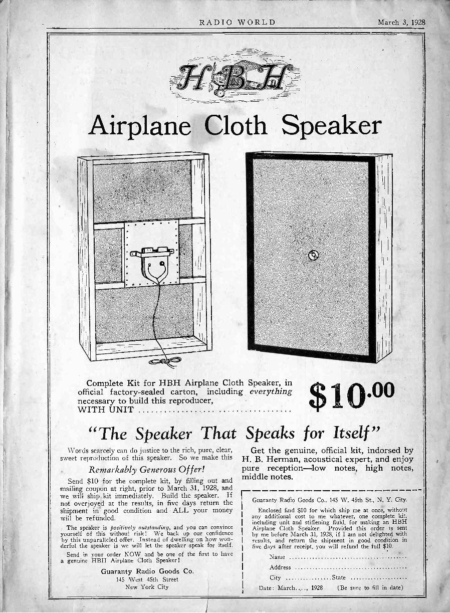
RADIO WORLD March 3, 1928
Airplane Cloth Speaker
Complete Kit for HBH Airplane Cloth Speaker, inofficial factory -sealed carton, including everything $10.00necessary to build this reproducer,WITH UNIT
"The Speaker That Speaks for Itself"Words scarcely can do justice to the rich, pure, clear,
sweet reproduction of this speaker. So we make this
Remarkably Generous Offer!Send $10 for the complete kit, by filling out and
mailing coupon at right, prior to March 31, 1928, andwe will ship kit immediately. Build the speaker. Ifnot overjoyed at the results, in five days return theshipment in good condition and ALL your moneywill be refunded.
The speaker is positively outstanding, and you can convinceyourself of this without risk! We back up our confidenceby this unparalleled offer. Instead of dwelling on how won-derful the speaker is we will let the speaker speak for itself.
Send in your order NOW and be one of the first to havea genuine HBH Airplane Cloth Speaker!
Guaranty Radio Goods Co.145 West 45th Street
New York City
Get the genuine, official kit, indorsed byH. B. Herman, acoustical expert, and enjoypure reception-low notes, high notes,middle notes.
Guaranty Radio Goods Co.. 145 W. 45th St., N. Y. City.
Enclosed find $10 for which ship me at once, withoutany additional cost to me whatever, one complete kit,including unit and stiffening fluid, for making an HBHAirplane Cloth Speaker. Provided this order is sentby me before March 31, 1928, if I am not delighted withresults, and return the shipment in good condition infive days after receipt, you will refund the full $10.
Name
Address
City State
Date : March....., 1928 (Be sure to fill in date)