rra study of - welcome to...
TRANSCRIPT
RRA Study of
DHT Project, NRL,
Assam
Doc No: A800-17-43-RA-0001
Rev. No.: 1
Page 2 of 36
Template No. 5-0000-0001-T2 Rev. 1 Copyrights EIL ¬ All rights reserved
PREFACE
NRL is in the process of implementing 0.7 MMTPA Diesel Hydrotreater Unit (DHT) & other
supporting units and utilities for production of BS IV & BS V grade HSD. Engineers India Limited
(EIL), New Delhi, has been entrusted by M/s Numaligarh Refinery Limited, Assam (NRL) as
Consultant for this Project.
In this perspective, NRL has appointed EIL to carry out the Rapid Risk Analysis Study of the units
under scope of DHT Project.
Rapid Risk Analysis study identifies the hazards associated with the facility, analyses the
consequences, draws suitable conclusions and provides necessary recommendations to mitigate
the hazard/ risk.
This Rapid Risk Analysis study is based on the information made available at the time of this
study and EIL’s own data source for similar plants. EIL has exercised all reasonable skill, care
and diligence in carrying out the study. However, this report is not deemed to be any undertaking,
warrantee or certificate.

RRA Study of
DHT Project, NRL,
Assam
Doc No: A800-17-43-RA-0001
Rev. No.: 1
Page 3 of 36
Template No. 5-0000-0001-T2 Rev. 1 Copyrights EIL ¬ All rights reserved
TABLE OF CONTENTS
1 EXECUTIVE SUMMARY ....................................................................................................... 6
1.1 INTRODUCTION ............................................................................................................ 6
1.2 APPROACH METHODOLOGY ....................................................................................... 6
1.3 MAJOR FINDINGS AND RECOMMENDATIONS ........................................................... 6
2 INTRODCUTION ................................................................................................................. 10
2.1 STUDY AIMS AND OBJECTIVE ................................................................................... 10
2.2 SCOPE OF WORK ....................................................................................................... 10
3 SITE CONDITION ................................................................................................................ 11
3.1 GENERAL .................................................................................................................... 11
3.2 SITE, LOCATION AND VICINITY ................................................................................. 11
3.3 METEOROLOGICAL CONDITIONS ............................................................................. 11
4 HAZARDS ASSOCIATED WITH THE FACILITIES .............................................................. 15
4.1 GENERAL .................................................................................................................... 15
4.2 HAZARDS ASSOCIATED WITH FLAMMABLE MATERIALS........................................ 15
4.2.1 LIQUIFIED PETROLEUM GAS .............................................................................. 15
4.2.2 HYDROGEN .......................................................................................................... 15
4.2.3 NAPHTHA AND OTHER HEAVIER HYDROCARBONS ........................................ 16
4.3 HAZARDS ASSOCIATED WITH TOXIC MATERIALS .................................................. 17
4.3.1 HYDROGEN SULPHIDE ....................................................................................... 17
4.3.2 AMMONIA ............................................................................................................. 17
5 HAZARD IDENTIFICATION ................................................................................................. 18
5.1 GENERAL .................................................................................................................... 18
5.2 MODES OF FAILURE ................................................................................................... 18
5.3 SELECTED FAILURE CASES ...................................................................................... 19
6 CONSEQUENCE ANALYSIS ............................................................................................... 21
6.1 GENERAL .................................................................................................................... 21
6.2 CONSEQUENCE ANALYSIS MODELLING .................................................................. 21
6.2.1 DISCHARGE RATE ............................................................................................... 21
6.2.2 DISPERSION ......................................................................................................... 21

RRA Study of
DHT Project, NRL,
Assam
Doc No: A800-17-43-RA-0001
Rev. No.: 1
Page 4 of 36
Template No. 5-0000-0001-T2 Rev. 1 Copyrights EIL ¬ All rights reserved
6.2.3 FLASH FIRE .......................................................................................................... 21
6.2.4 JET FIRE ............................................................................................................... 22
6.2.5 POOL FIRE ........................................................................................................... 22
6.2.6 VAPOR CLOUD EXPLOSION ............................................................................... 22
6.2.7 TOXIC RELEASE .................................................................................................. 22
6.3 SIZE AND DURATION OF RELEASE ........................................................................... 22
6.4 DAMAGE CRITERIA ..................................................................................................... 23
6.4.1 LFL OR FLASH FIRE ............................................................................................. 23
6.4.2 THERMAL HAZARD DUE TO POOL FIRE, JET FIRE AND FIRE BALL ................ 23
6.4.3 VAPOR CLOUD EXPLOSION ............................................................................... 24
6.4.4 TOXIC HAZARD .................................................................................................... 24
6.5 CONSEQUENCE ANALYSIS FOR UNITS.................................................................... 24
6.5.1 DHT ....................................................................................................................... 25
6.5.2 SRU ....................................................................................................................... 28
6.5.3 EXISTING ARU & SWS ......................................................................................... 28
6.5.4 OFFSITES ............................................................................................................. 29
7 MAJOR FINDINGS & RECOMMENDATIONS ..................................................................... 30
8 GLOSSARY ......................................................................................................................... 34
9 REFERENCES .................................................................................................................... 36
ANNEXURE-I: CONSEQUENCE ANALYSIS HAZARD DISTANCES
ANNEXURE-II: FIGURES FOR CONSEQUENCE ANALYSIS
LIST OF TABLES
Table 1: New Proposed Process Facilities under DHT Project .................................................... 10
Table 2: Existing Process Facilities under DHT Project ............................................................... 10
Table 3: Offsite facilities –Storage tanks ..................................................................................... 10
Table 4: Atmospheric Parameter ................................................................................................. 12
Table 5: Average Mean Wind Speed (m/s) .................................................................................. 12
Table 6: % Number of Days Wind From ...................................................................................... 12
Table 7: Pasquill Stability Classes ............................................................................................... 13
RRA Study of
DHT Project, NRL,
Assam
Doc No: A800-17-43-RA-0001
Rev. No.: 1
Page 5 of 36
Template No. 5-0000-0001-T2 Rev. 1 Copyrights EIL ¬ All rights reserved
Table 8: Weather Conditions ....................................................................................................... 14
Table 9: Hazardous Properties of LPG ........................................................................................ 15
Table 10: Hazardous Properties of Hydrogen ............................................................................. 16
Table 11: Hazardous Properties of Naphtha ............................................................................... 16
Table 12: Toxic Effects of Hydrogen Sulphide ............................................................................. 17
Table 13: Toxic Effects of Ammonia ............................................................................................ 17
Table 14: Size of Release ........................................................................................................... 22
Table 15: Damage Due to Incident Thermal Radiation Intensity .................................................. 23
Table 16: Damage Effects of Blast Overpressure ........................................................................ 24
LIST OF FIGURES
Figure 1: NRL Site ...................................................................................................................... 11
RRA Study of
DHT Project, NRL,
Assam
Doc No: A800-17-43-RA-0001
Rev. No.: 1
Page 6 of 36
Template No. 5-0000-0001-T2 Rev. 1 Copyrights EIL ¬ All rights reserved
1 EXECUTIVE SUMMARY
1.1 INTRODUCTION
NRL, a subsidiary of M/s Bharat Petroleum Corporation Limited presently operates a 3.0 MMTPA
refinery at Numaligarh, Golaghat, Assam. The Refinery presently produces Euro-III and part Euro-
IV grade HSD. NRL is in the process of implementing 0.7 MMTPA Diesel Hydrotreater Unit (DHT)
& other supporting units and utilities for production of BS IV & BS V grade HSD in line with the
AFYP 2025 requirements. EIL has been selected as consultant for the DHT Project.
In this context, NRL has also entrusted EIL to carry out the Rapid Risk Analysis Study of the units
under scope of DHT Project.
This executive summary covers major findings arising out of the Rapid Risk Analysis study and
recommendations for the facilities under DHT Project, NRL-Assam. The detailed analysis is given
in Section –6.
1.2 APPROACH METHODOLOGY
RRA study evaluates the consequences of potential failure scenarios, assess extent of damages,
based on damage criteria’s and suggest suitable measures for mitigating the Hazard.
RRA involves identification of various potential hazards & credible failure scenarios for various
units and other facilities including off-site storages & pumping, etc., based on their frequency of
occurrence & resulting consequence. Basically two types of scenarios are identified spanning
across various process facilities; Cases with high chance of occurrence but having low
consequence, e.g., Instrument Tapping Failure and cases with low chance of occurrence but
having high consequence, e.g., Catastrophic Rupture of Pressure Vessels / Large Hole on the
outlet of Pressure Vessels. Effect zones for various outcomes of failure scenarios (Flash Fire, Jet
Fire, Pool Fire, Blast overpressure, toxic release, etc.) are studied and identified in terms of
distances on plot plan. Based on effect zones, measures for mitigation of the hazard/risk are
suggested.
1.3 MAJOR FINDINGS AND RECOMMENDATIONS
The detailed consequence analysis of release of hydrocarbon in case of major credible scenarios
are modeled in terms of release rate, dispersion, flammability and toxic characteristics, which
have been discussed in detail in the report. The major findings and recommendations arising out
of the Rapid Risk analysis study for units under DHT Project are summarized below:
Consequence modeling of low frequency failure scenarios for DHT is carried out and it was
observed that in the event of realization of failure scenarios (Large Hole in Feed Surge Drum,
HP Cold Separator, LP Cold Separator, Product Stripper, Naphtha Stabilizer), radiation &
explosion effect zones may get extended up to adjacent Hydro-finishing unit on eastern side
& Fire station, Lab Building, Medical Center on western side.

RRA Study of
DHT Project, NRL,
Assam
Doc No: A800-17-43-RA-0001
Rev. No.: 1
Page 7 of 36
Template No. 5-0000-0001-T2 Rev. 1 Copyrights EIL ¬ All rights reserved
Further, in the event of Large Hole failure scenarios in HP Cold Separator, LP Cold
Separator, Product Stripper, 5 & 3 psi blast waves may extend beyond the Refinery
compound wall on southern side depending upon the prevalent weather condition and
presence of ignition source at the time of release.
Since, these are low frequency credible failure scenarios, outcomes of the above to be
utilized for updation of the existing Disaster Management Plan (DMP) & Emergency
Response Plan (ERP). Adequate number of hydrocarbon detectors to be ensured at strategic
locations within the DHT unit for early leak detection and inventory isolation.
High frequency credible failure scenarios are also modeled for DHT unit and their explosion &
radiation effects are analyzed. It is observed that, in the event of the Instrument tapping
failure at feed charge pump, LFL may get extended up to a distance of 76 m, covering SRR-1
and sub-station area present on the western side of the unit.
The Jet fire radiation intensity of 37.5 & 12.5 kW/m2 may be realized up to a distance of 60 m
& 73 m respectively and may affect SRR-1 & sub-station.
5 & 3 psi blast overpressure wave may reach up to a distance of 88 m & 95 m respectively.
These pressure waves may cause damage to SRR-1, Substation and Caustic solution tank.
On the western side, 2 psi blast overpressure wave may reach up to existing fire station last
bay, depending upon the prevalent weather condition and presence of ignition source at the
time of release.
Last bay (maintenance bay) of existing Fire Station is under affect zone of high frequency
credible scenario (Instrument tapping failure at Feed charge pump). Being a maintenance
bay, no Fire Tender is expected to be present regularly in this bay. However, it is
recommended to ensure that Fire tender is not stationed on permanent basis in the last bay.
Toxic gas dispersion modelling is also carried out for various high frequency credible failure
scenarios for DHT (Instrument Tapping Failure at HP Cold Separator Overhead, Recycle Gas
Compressor, Stripper Reflux Drum Overhead & Flange Leakage at Stripper Reflux Pump)
and it is observed that H2S IDLH hazard distance may extend beyond DHT unit battery limit.
However, the affect zone is confined within the Refinery Compound wall.
Hence, it is recommended to locate the toxic gas detectors within the DHT unit at strategic
locations and utilize the outcomes of these failure scenarios in the updation of the existing
Disaster Management Plan (DMP) & Emergency Response Plan (ERP).
Toxic gas credible failure scenarios are modeled for SRU. It is observed that in the event of
Instrument tapping failure at Acid Gas KOD & Sour Gas KOD under 1F weather condition,
H2S IDLH concentration may extend up to a distance of 283 m & 307 m respectively, from the
leak source, depending upon the prevailing wind conditions at the time of release. H2S IDLH
concentration may extend beyond the Refinery compound wall on southern side & may affect
the nearby personnel’s.
1

RRA Study of
DHT Project, NRL,
Assam
Doc No: A800-17-43-RA-0001
Rev. No.: 1
Page 8 of 36
Template No. 5-0000-0001-T2 Rev. 1 Copyrights EIL ¬ All rights reserved
Hence, it is recommended to install toxic gas detectors within SRU at strategic locations and
utilize the outcome of these failure scenarios in the updation of the existing Disaster
Management Plan (DMP) & Emergency Response Plan (ERP). Moreover, due to close
proximity of another Sulphur Block, it is recommended to carry out Quantitative Risk Analysis
(QRA) of the refinery, so as to assess the effect of the H2S IDLH concentration in terms of
Individual & Societal Risk on the nearby buildings / operator cabins / populations.
a) Recommendations for Construction Safety during execution of the DHT Project
Adequate barricading of the proposed unit to be done from existing running process units
during construction phase. Hydrocarbon / toxic detectors to be placed along the
barricading suitably to detect any hydrocarbon / toxic gas in vicinity of construction area.
Also, adequate firefighting & toxic gas handling arrangement are to be ensured in the
construction area. Ensure training of persons associated with construction activities for
response during fire & toxic gas release.
Proper material movement path within the Refinery shall be identified during the
construction phase of the project.
Detailed HSE Plan & HSE Philosophy to be developed by contractors during construction
phase of the project, in line with client’s safety requirements.
It is suggested to carry out HAZID, SIMOPS studies during pre-execution phase of the
DHT project to get a detailed overview of the possible hazards during construction phase
and action plan to prevent / mitigate the same.
b) General Recommendations
No operator cabin shall be located inside battery limits of proposed units under DHT
project. Also, operator cabin, if any located in the vicinity of unit shall be made of Blast
Resistant Construction with Positive Pressurization for protection of individuals inside
operator cabin from Explosion, Radiation & Toxic effects of various leak scenarios.
Proper checking of contract people for smoking or inflammable materials to be ensured at
entry gates to avoid presence of any unidentified source of ignition.
Ensure vehicles entering the Refinery are fitted with spark arrestors, as a mandatory item.
In order to prevent secondary incident arising from any failure scenario, it is recommended
that sprinklers and other protective devices provided on the tanks are regularly checked to
ensure these are functional.
Mock drills to be organized at organization level to ensure preparation of the personnel’s
working in Refinery for handling any hazardous situation.
For positively pressurized building, both Hydrocarbon & Toxic detectors need to be placed
at suction duct of HVAC. HVAC to be tripped automatically in event of the detection of any
Hydrocarbon / toxic material by detector.
Ensure usage of safer oxidizing agents (Chlorine free) in Cooling Water circuit.

RRA Study of
DHT Project, NRL,
Assam
Doc No: A800-17-43-RA-0001
Rev. No.: 1
Page 9 of 36
Template No. 5-0000-0001-T2 Rev. 1 Copyrights EIL ¬ All rights reserved
c) Mitigating Measures
Mitigating measures are those measures in place to minimize the loss of containment event and,
hazards arising out of Loss of containment. These include:
Early detection of an undesirable event (HC leak, Toxic gas leak, Flame etc.) and
development of subsequent quick isolation mechanism for major inventories.
Measures for controlling / minimization of Ignition sources inside the Refinery complex.
Active and Passive Fire Protection for critical equipment’s and major structures
Effective Emergency Response plans to be in place
d) Ignition Control
Ignition control will reduce the likelihood of fire events. This is the key for reducing the risk
within facilities processing flammable materials. As part of mitigation measure it strongly
recommended to consider minimization of the traffic movement within the Refinery.
e) Escape Routes
Ensure sufficient escape routes from the site are available to allow redundancy in escape
from all areas.
Ensure sufficient number of windsocks throughout the site to ensure visibility from all
locations. This will enable people to escape upwind or crosswind from flammable / toxic
releases.
Provide sign boards marking emergency/safe roads to be taken during any exigencies.
f) Preventive Maintenance for Critical Equipment’s
In order to reduce the failure frequency of critical equipment’s, the following are
recommended:
a. High head pumps and Compressors, which are in flammable / toxic services, are
needed to be identified.
i. Their seals, instruments and accessories are to be monitored closely
ii. A detailed preventive maintenance plan to be prepared and followed.
b. Surge Drums & Reflux drums and high inventory vessels whose rupture may lead
to massive consequences are needed to be identified and following to be ensured:
i. Monitoring of vessel internals during shut down.
ii. A detailed preventive maintenance plan to be prepared and followed.
g) Others
Ensure removal of hammer blinds from the process facilities, if any.
Closed sampling system to be considered for pressurized services like LPG, Propylene
etc.
Recommended to use portable HC detector during sampling and maintenance etc.
Provide breathing apparatus at strategic locations inside Refinery.

RRA Study of
DHT Project, NRL,
Assam
Doc No: A800-17-43-RA-0001
Rev. No.: 1
Page 10 of 36
Template No. 5-0000-0001-T2 Rev. 1 Copyrights EIL ¬ All rights reserved
2 INTRODCUTION
2.1 STUDY AIMS AND OBJECTIVE
The objectives of the Rapid Risk Analysis study are to identify and quantify all potential failure
modes that may lead to hazardous consequences and extent. Typical hazardous consequences
include fire, explosion and toxic releases.
The Rapid Risk analysis will also identify potential hazardous consequences having impacts on
population and property in the vicinity of the facilities, and provides information necessary in
developing strategies to prevent accidents and formulate the Disaster Management Plan.
The Rapid Risk Analysis includes the following steps:
a) Identification of failure cases within the process and off-site facilities
b) Evaluate process hazards emanating from the identified potential accident scenarios.
c) Analyze the damage effects to surroundings due to such incidents.
d) Suggest mitigating measures to reduce the hazard / risk.
The Risk analysis study has been carried out using the risk assessment software program
‘PHAST ver. 7.11 developed by DNV Technica.
2.2 SCOPE OF WORK
The study addresses the hazards that can be realized due to operations associated with the
proposed facilities under DHT Project. It covers the following facilities of Refinery:
Table 1: New Proposed Process Facilities under DHT Project
S. No. Description Remarks
1. DHT
2. SRU
Table 2: Existing Process Facilities under DHT Project
S. No. Description Remarks
1. SWS Revamp
2. ARU Revamp
Table 3: Offsite facilities –Storage tanks
S. No. Facility Remarks
1. DHT Feed Storage Tanks
2. DHT Feed Pump
RRA Study of
DHT Project, NRL,
Assam
Doc No: A800-17-43-RA-0001
Rev. No.: 1
Page 11 of 36
Template No. 5-0000-0001-T2 Rev. 1 Copyrights EIL ¬ All rights reserved
3 SITE CONDITION
3.1 GENERAL
This chapter describes the location of Numaligarh Refinery complex and meteorological data,
which have been used for the Rapid Risk Analysis study.
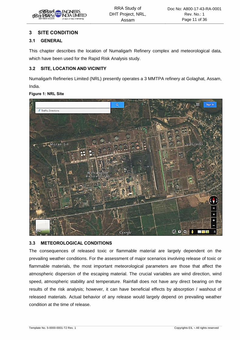
3.2 SITE, LOCATION AND VICINITY
Numaligarh Refineries Limited (NRL) presently operates a 3 MMTPA refinery at Golaghat, Assam,
India.
Figure 1: NRL Site
3.3 METEOROLOGICAL CONDITIONS
The consequences of released toxic or flammable material are largely dependent on the
prevailing weather conditions. For the assessment of major scenarios involving release of toxic or
flammable materials, the most important meteorological parameters are those that affect the
atmospheric dispersion of the escaping material. The crucial variables are wind direction, wind
speed, atmospheric stability and temperature. Rainfall does not have any direct bearing on the
results of the risk analysis; however, it can have beneficial effects by absorption / washout of
released materials. Actual behavior of any release would largely depend on prevailing weather
condition at the time of release.
RRA Study of
DHT Project, NRL,
Assam
Doc No: A800-17-43-RA-0001
Rev. No.: 1
Page 12 of 36
Template No. 5-0000-0001-T2 Rev. 1 Copyrights EIL ¬ All rights reserved
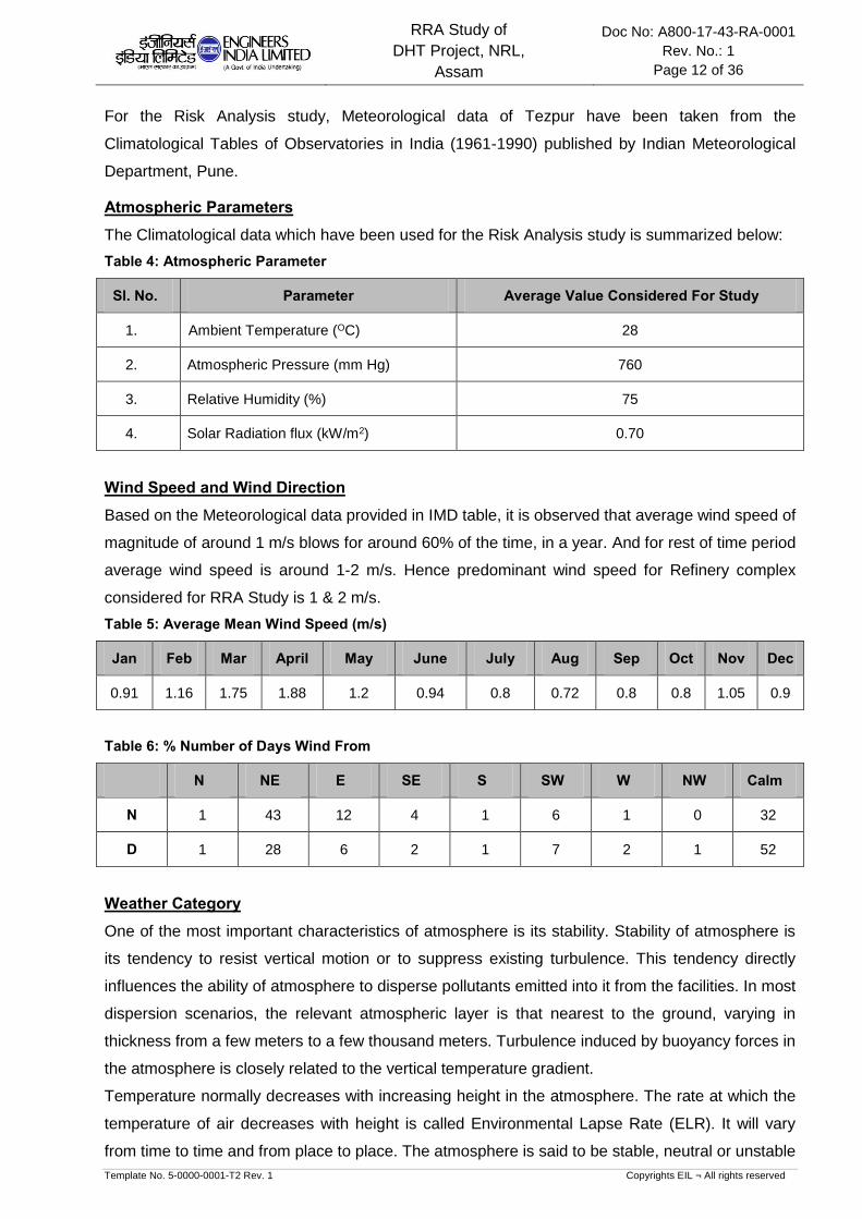
For the Risk Analysis study, Meteorological data of Tezpur have been taken from the
Climatological Tables of Observatories in India (1961-1990) published by Indian Meteorological
Department, Pune.
Atmospheric Parameters
The Climatological data which have been used for the Risk Analysis study is summarized below:
Table 4: Atmospheric Parameter
Sl. No. Parameter Average Value Considered For Study
1. Ambient Temperature (OC) 28
2. Atmospheric Pressure (mm Hg) 760
3. Relative Humidity (%) 75
4. Solar Radiation flux (kW/m2) 0.70
Wind Speed and Wind Direction
Based on the Meteorological data provided in IMD table, it is observed that average wind speed of
magnitude of around 1 m/s blows for around 60% of the time, in a year. And for rest of time period
average wind speed is around 1-2 m/s. Hence predominant wind speed for Refinery complex
considered for RRA Study is 1 & 2 m/s.
Table 5: Average Mean Wind Speed (m/s)
Jan Feb Mar April May June July Aug Sep Oct Nov Dec
0.91 1.16 1.75 1.88 1.2 0.94 0.8 0.72 0.8 0.8 1.05 0.9
Table 6: % Number of Days Wind From
N NE E SE S SW W NW Calm
N 1 43 12 4 1 6 1 0 32
D 1 28 6 2 1 7 2 1 52
Weather Category
One of the most important characteristics of atmosphere is its stability. Stability of atmosphere is
its tendency to resist vertical motion or to suppress existing turbulence. This tendency directly
influences the ability of atmosphere to disperse pollutants emitted into it from the facilities. In most
dispersion scenarios, the relevant atmospheric layer is that nearest to the ground, varying in
thickness from a few meters to a few thousand meters. Turbulence induced by buoyancy forces in
the atmosphere is closely related to the vertical temperature gradient.
Temperature normally decreases with increasing height in the atmosphere. The rate at which the
temperature of air decreases with height is called Environmental Lapse Rate (ELR). It will vary
from time to time and from place to place. The atmosphere is said to be stable, neutral or unstable

RRA Study of
DHT Project, NRL,
Assam
Doc No: A800-17-43-RA-0001
Rev. No.: 1
Page 13 of 36
Template No. 5-0000-0001-T2 Rev. 1 Copyrights EIL ¬ All rights reserved
according to ELR is less than, equal to or greater than Dry Adiabatic Lapse Rate (DALR), which is
a constant value of 0.98°C/100 meters.
Pasquill stability parameter, based on Pasquill – Gifford categorization, is such a meteorological
parameter, which decreases the stability of atmosphere, i.e., the degree of convective turbulence.
Pasquill has defined six stability classes ranging from `A' (extremely unstable) to `F' (stable). Wind
speeds, intensity of solar radiation (daytime insulation) and nighttime sky cover have been
identified as prime factors defining these stability categories. Below Table indicates the various
Pasquill stability classes.
Table 7: Pasquill Stability Classes
Surface Wind Speed
(meter/s)
Day time solar radiation Night time cloud cover
Strong Medium Slight Thin < 3/8 Medium 3/8 Overcast >4/5
< 2 A A – B B - - D
2 – 3 A – B B C E F D
3 – 5 B B – C C D E D
5 – 6 C C – D D D D D
> 6 C D D D D D
Legend: A = Very unstable, B = Unstable, C = Moderately unstable, D = Neutral, E = Moderately
stable, F = stable
When the atmosphere is unstable and wind speeds are moderate or high or gusty, rapid
dispersion of pollutants will occur. Under these conditions, pollutant concentrations in air will be
moderate or low and the material will be dispersed rapidly. When the atmosphere is stable and
wind speed is low, dispersion of material will be limited and pollutant concentration in air will be
high. In general worst dispersion conditions (i.e. contributing to greater hazard distances) occur
during low wind speed and very stable weather conditions, such as that at 1F weather condition
(i.e. 1 m/s wind speed and Pasquill Stability F).
Stability category for the present study is identified based on the cloud amount and wind speed.
For risk analysis the representative average annual weather conditions are assessed based on
the following:
Average Wind speed in order of 1 m/s would be experienced for more than 60% of time in a year
and Wind speed of 1-2 m/s can be realized in the month of Feb to May. Based on weather
analysis, predominant weather stability of “F”& “D” was selected with wind speed 1 m/s & 2 m/s
for consequence analysis, respectively.
The consequence results are reported in tabular form for all the weather conditions and are
represented graphically for worst weather condition.

RRA Study of
DHT Project, NRL,
Assam
Doc No: A800-17-43-RA-0001
Rev. No.: 1
Page 14 of 36
Template No. 5-0000-0001-T2 Rev. 1 Copyrights EIL ¬ All rights reserved
Table 8: Weather Conditions
Wind Speed Pasquill Stability
1 F
2 D
Note: For RRA Study Plot Plan (Doc. No.: A774-000-17-44-0001 Rev N) has been used. 1
RRA Study of
DHT Project, NRL,
Assam
Doc No: A800-17-43-RA-0001
Rev. No.: 1
Page 15 of 36
Template No. 5-0000-0001-T2 Rev. 1 Copyrights EIL ¬ All rights reserved
4 HAZARDS ASSOCIATED WITH THE FACILITIES
4.1 GENERAL
Refinery complex handles a number of hazardous materials like LPG, Hydrogen, Naphtha and
other hydrocarbons which have a potential to cause fire and explosion hazards. The toxic
chemicals like Ammonia and Hydrogen sulfide are also handled in the Refinery. This chapter
describes in brief the hazards associated with these materials.
4.2 HAZARDS ASSOCIATED WITH FLAMMABLE MATERIALS
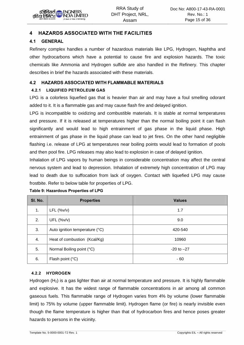
4.2.1 LIQUIFIED PETROLEUM GAS
LPG is a colorless liquefied gas that is heavier than air and may have a foul smelling odorant
added to it. It is a flammable gas and may cause flash fire and delayed ignition.
LPG is incompatible to oxidizing and combustible materials. It is stable at normal temperatures
and pressure. If it is released at temperatures higher than the normal boiling point it can flash
significantly and would lead to high entrainment of gas phase in the liquid phase. High
entrainment of gas phase in the liquid phase can lead to jet fires. On the other hand negligible
flashing i.e. release of LPG at temperatures near boiling points would lead to formation of pools
and then pool fire. LPG releases may also lead to explosion in case of delayed ignition.
Inhalation of LPG vapors by human beings in considerable concentration may affect the central
nervous system and lead to depression. Inhalation of extremely high concentration of LPG may
lead to death due to suffocation from lack of oxygen. Contact with liquefied LPG may cause
frostbite. Refer to below table for properties of LPG.
Table 9: Hazardous Properties of LPG
Sl. No. Properties Values
1. LFL (%v/v) 1.7
2. UFL (%v/v) 9.0
3. Auto ignition temperature (°C) 420-540
4. Heat of combustion (Kcal/Kg) 10960
5. Normal Boiling point (°C) -20 to –27
6. Flash point (°C) - 60
4.2.2 HYDROGEN
Hydrogen (H2) is a gas lighter than air at normal temperature and pressure. It is highly flammable
and explosive. It has the widest range of flammable concentrations in air among all common
gaseous fuels. This flammable range of Hydrogen varies from 4% by volume (lower flammable
limit) to 75% by volume (upper flammable limit). Hydrogen flame (or fire) is nearly invisible even
though the flame temperature is higher than that of hydrocarbon fires and hence poses greater
hazards to persons in the vicinity.
RRA Study of
DHT Project, NRL,
Assam
Doc No: A800-17-43-RA-0001
Rev. No.: 1
Page 16 of 36
Template No. 5-0000-0001-T2 Rev. 1 Copyrights EIL ¬ All rights reserved
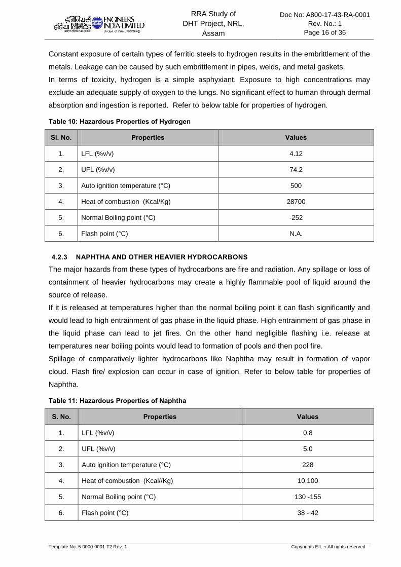
Constant exposure of certain types of ferritic steels to hydrogen results in the embrittlement of the
metals. Leakage can be caused by such embrittlement in pipes, welds, and metal gaskets.
In terms of toxicity, hydrogen is a simple asphyxiant. Exposure to high concentrations may
exclude an adequate supply of oxygen to the lungs. No significant effect to human through dermal
absorption and ingestion is reported. Refer to below table for properties of hydrogen.
Table 10: Hazardous Properties of Hydrogen
Sl. No. Properties Values
1. LFL (%v/v) 4.12
2. UFL (%v/v) 74.2
3. Auto ignition temperature (°C) 500
4. Heat of combustion (Kcal/Kg) 28700
5. Normal Boiling point (°C) -252
6. Flash point (°C) N.A.
4.2.3 NAPHTHA AND OTHER HEAVIER HYDROCARBONS
The major hazards from these types of hydrocarbons are fire and radiation. Any spillage or loss of
containment of heavier hydrocarbons may create a highly flammable pool of liquid around the
source of release.
If it is released at temperatures higher than the normal boiling point it can flash significantly and
would lead to high entrainment of gas phase in the liquid phase. High entrainment of gas phase in
the liquid phase can lead to jet fires. On the other hand negligible flashing i.e. release at
temperatures near boiling points would lead to formation of pools and then pool fire.
Spillage of comparatively lighter hydrocarbons like Naphtha may result in formation of vapor
cloud. Flash fire/ explosion can occur in case of ignition. Refer to below table for properties of
Naphtha.
Table 11: Hazardous Properties of Naphtha
S. No. Properties Values
1. LFL (%v/v) 0.8
2. UFL (%v/v) 5.0
3. Auto ignition temperature (°C) 228
4. Heat of combustion (Kcal//Kg) 10,100
5. Normal Boiling point (°C) 130 -155
6. Flash point (°C) 38 - 42
RRA Study of
DHT Project, NRL,
Assam
Doc No: A800-17-43-RA-0001
Rev. No.: 1
Page 17 of 36
Template No. 5-0000-0001-T2 Rev. 1 Copyrights EIL ¬ All rights reserved
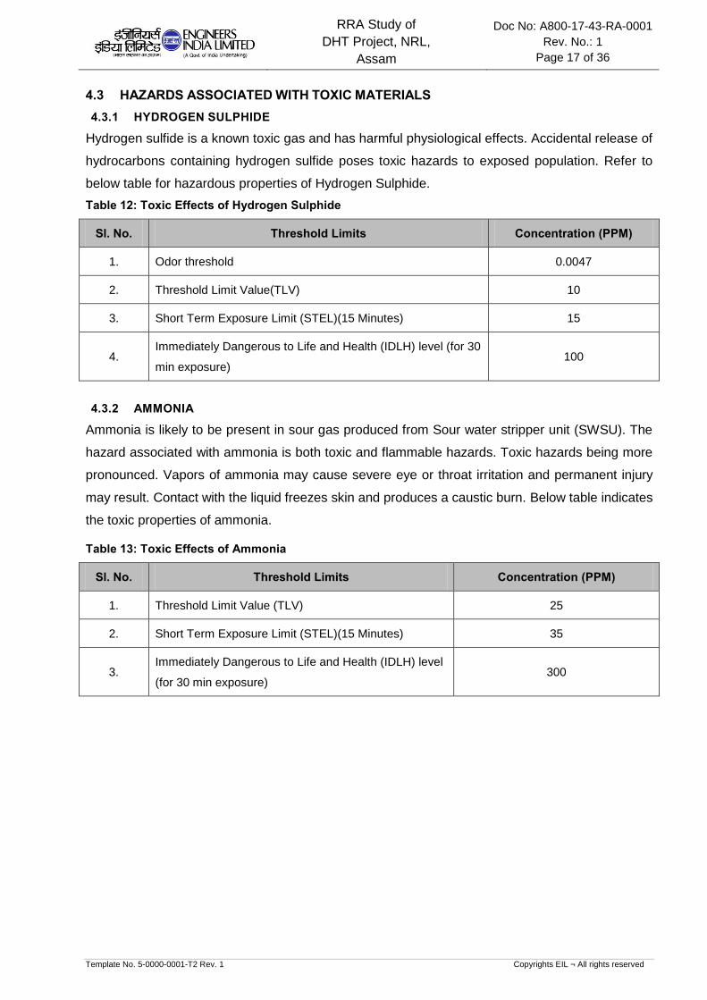
4.3 HAZARDS ASSOCIATED WITH TOXIC MATERIALS
4.3.1 HYDROGEN SULPHIDE
Hydrogen sulfide is a known toxic gas and has harmful physiological effects. Accidental release of
hydrocarbons containing hydrogen sulfide poses toxic hazards to exposed population. Refer to
below table for hazardous properties of Hydrogen Sulphide.
Table 12: Toxic Effects of Hydrogen Sulphide
Sl. No. Threshold Limits Concentration (PPM)
1. Odor threshold 0.0047
2. Threshold Limit Value(TLV) 10
3. Short Term Exposure Limit (STEL)(15 Minutes) 15
4. Immediately Dangerous to Life and Health (IDLH) level (for 30
min exposure) 100
4.3.2 AMMONIA
Ammonia is likely to be present in sour gas produced from Sour water stripper unit (SWSU). The
hazard associated with ammonia is both toxic and flammable hazards. Toxic hazards being more
pronounced. Vapors of ammonia may cause severe eye or throat irritation and permanent injury
may result. Contact with the liquid freezes skin and produces a caustic burn. Below table indicates
the toxic properties of ammonia.
Table 13: Toxic Effects of Ammonia
Sl. No. Threshold Limits Concentration (PPM)
1. Threshold Limit Value (TLV) 25
2. Short Term Exposure Limit (STEL)(15 Minutes) 35
3. Immediately Dangerous to Life and Health (IDLH) level
(for 30 min exposure) 300

RRA Study of
DHT Project, NRL,
Assam
Doc No: A800-17-43-RA-0001
Rev. No.: 1
Page 18 of 36
Template No. 5-0000-0001-T2 Rev. 1 Copyrights EIL ¬ All rights reserved
5 HAZARD IDENTIFICATION
5.1 GENERAL
A classical definition of hazard states that hazard is in fact the characteristic of
system/plant/process that presents potential for an accident. Hence all the components of a
system/plant/process need to be thoroughly examined in order to assess their potential for
initiating or propagating an unplanned event/sequence of events, which can be termed as an
accident.
In Risk Analysis terminology a hazard is something with the potential to cause harm. Hence the
Hazard Identification step is an exercise that seeks to identify what can go wrong at the major
hazard installation or process in such a way that people may be harmed. The output of this step is
a list of events that need to be passed on to later steps for further analysis.
The potential hazards posed by the facility were identified based on the past accidents, lessons
learnt and a checklist. This list includes the following elements.
Catastrophic Rupture of Pressure vessel
Large hole on outlet of process vessel
“Guillotine-Breakage” of pipe-work
Small hole, cracks or small bore failure (i.e. instrument tapping failure, drains/vents failure
etc.) in piping and vessels.
Flange leaks.
Storage Tank on fire
Leaks from pump glands and similar seals.
5.2 MODES OF FAILURE
There are various potential sources of large leakage, which may release hazardous chemicals
and hydrocarbon materials into the atmosphere. These could be in form of gasket failure in
flanged joints, bleeder valve left open inadvertently, an instrument tubing giving way, pump seal
failure, guillotine failure of equipment/ pipeline or any other source of leakage. Operating
experience can identify lots of these sources and their modes of failure. A list of general
equipment and pipeline failure mechanisms is as follows:
Material/Construction Defects
Incorrect selection or supply of materials of construction
Incorrect use of design codes
Weld failures
Failure of inadequate pipeline supports
Pre-Operational Failures
Failure induced during delivery at site
Failure induced during installation
Pressure and temperature effects

RRA Study of
DHT Project, NRL,
Assam
Doc No: A800-17-43-RA-0001
Rev. No.: 1
Page 19 of 36
Template No. 5-0000-0001-T2 Rev. 1 Copyrights EIL ¬ All rights reserved
Overpressure
Temperature expansion/contraction (improper stress analysis and support design)
Low temperature brittle fracture (if metallurgy is incorrect)
Fatigue loading (cycling and mechanical vibration)
Corrosion Failures
Internal corrosion (e.g. ingress of moisture)
External corrosion
Cladding/insulation failure (e.g. ingress of moisture)
Cathodic protection failure, if provided
Failures due to Operational Errors
Human error
Failure to inspect regularly and identify any defects
External Impact Induced Failures
Dropped objects
Impact from transport such as construction traffic
Vandalism
Subsidence
Strong winds
Failure due to Fire
External fire impinging on pipeline or equipment
Rapid vaporization of cold liquid in contact with hot surfaces
5.3 SELECTED FAILURE CASES
A list of selected failure cases was prepared based on process knowledge, engineering judgment,
experience, past incidents associated with such facilities and considering the general
mechanisms for loss of containment. A list of cases has been identified for the consequence
analysis study based on the following.
Cases with high chance of occurrence but having low consequence: Example of such
failure cases includes two-bolt gasket leak for flanges, seal failure for pumps, instrument
tapping failure, etc. The consequence results will provide enough data for planning routine
safety exercises. This will emphasize the area where operator's vigilance is essential.
Cases with low chance of occurrence but having high consequence (The example includes
Large hole on the outlet of pressure vessels, Catastrophic Rupture of Pressure Vessels,
etc.)
This approach ensures at least one representative case of all possible types of accidental
failure events, is considered for the consequence analysis. Moreover, the list below
includes at least one accidental case comprising of release of different sorts of highly
hazardous materials handled in the refinery. Although the list does not give complete failure
RRA Study of
DHT Project, NRL,
Assam
Doc No: A800-17-43-RA-0001
Rev. No.: 1
Page 20 of 36
Template No. 5-0000-0001-T2 Rev. 1 Copyrights EIL ¬ All rights reserved
incidents considering all equipment’s, units, but the consequence of a similar incident
considered in the list below could be used to foresee the consequence of that particular
accident.
For selected credible failure scenarios and likely consequences for units of Numaligarh Refinery
under DHT Project, refer Section-6.

RRA Study of
DHT Project, NRL,
Assam
Doc No: A800-17-43-RA-0001
Rev. No.: 1
Page 21 of 36
Template No. 5-0000-0001-T2 Rev. 1 Copyrights EIL ¬ All rights reserved
6 CONSEQUENCE ANALYSIS
6.1 GENERAL
Consequence analysis involves the application of the mathematical, analytical and computer
models for calculation of the effects and damages subsequent to a hydrocarbon / toxic release
accident.
Computer models are used to predict the physical behavior of hazardous incidents. The model
uses below mentioned techniques to assess the consequences of identified scenarios:
Modeling of discharge rates when holes develop in process equipment/pipe work
Modeling of the size & shape of the flammable/toxic gas clouds from releases in the
atmosphere
Modeling of the flame and radiation field of the releases that are ignited and burn as jet fire,
pool fire and flash fire
Modeling of the explosion fields of releases which are ignited away from the point of release
The different consequences (Flash fire, pool fire, jet fire and Explosion effects) of loss of
containment accidents depend on the sequence of events & properties of material released
leading to the either toxic vapor dispersion, fire or explosion or both.
6.2 CONSEQUENCE ANALYSIS MODELLING
6.2.1 DISCHARGE RATE
The initial rate of release through a leak depends mainly on the pressure inside the equipment,
size of the hole and phase of the release (liquid, gas or two-phase). The release rate decreases
with time as the equipment depressurizes. This reduction depends mainly on the inventory and
the action taken to isolate the leak and blow-down the equipment.
6.2.2 DISPERSION
Releases of gas into the open air form clouds whose dispersion is governed by the wind, by
turbulence around the site, the density of the gas and initial momentum of the release. In case of
flammable materials the sizes of these gas clouds above their Lower Flammable Limit (LFL) are
important in determining whether the release will ignite. In this study, the results of dispersion
modeling for flammable materials are presented LFL quantity.
6.2.3 FLASH FIRE
A flash fire occurs when a cloud of vapors/gas burns without generating any significant
overpressure. The cloud is typically ignited on its edge, remote from- the leak source. The
combustion zone moves through the cloud away from the ignition point. The duration of the flash
fire is relatively short but it may stabilize as a continuous jet fire from the leak source. For flash
fires, an approximate estimate for the extent of the total effect zone is the area over which the
cloud is above the LFL.

RRA Study of
DHT Project, NRL,
Assam
Doc No: A800-17-43-RA-0001
Rev. No.: 1
Page 22 of 36
Template No. 5-0000-0001-T2 Rev. 1 Copyrights EIL ¬ All rights reserved
6.2.4 JET FIRE
Jet fires are burning jets of gas or atomized liquid whose shape is dominated by the momentum of
the release. The jet flame stabilizes on or close to the point of release and continues until the
release is stopped. Jet fire can be realized, if the leakage is immediately ignited. The effect of jet
flame impingement is severe as it may cut through equipment, pipeline or structure. The damage
effect of thermal radiation is depended on both the level of thermal radiation and duration of
exposure.
6.2.5 POOL FIRE
A cylindrical shape of the pool fire is presumed. Pool-fire calculations are then carried out as part
of an accidental scenario, e.g. in case a hydrocarbon liquid leak from a vessel leads to the
formation of an ignitable liquid pool. First no ignition is assumed, and pool evaporation and
dispersion calculations are being carried out. Subsequently late pool fires (ignition following
spreading of liquid pool) are considered. If the release is bunded, the diameter is given by the size
of the bund. If there is no bund, then the diameter is that which corresponds with a minimum pool
thickness, set by the type of surface on which the pool is spreading.
6.2.6 VAPOR CLOUD EXPLOSION
A vapor cloud explosion (VCE) occurs if a cloud of flammable gas burns sufficiently quickly to
generate high overpressures (i.e. pressures in excess of ambient). The overpressure resulting
from an explosion of hydrocarbon gases is estimated considering the explosive mass available to
be the mass of hydrocarbon vapor between its lower and upper explosive limits.
6.2.7 TOXIC RELEASE
The aim of the toxic risk study is to determine whether the operators in the plant, people occupied
buildings and the public are likely to be affected by toxic substances. Toxic gas cloud e.g. H2S,
chlorine, Benzene etc. was undertaken to the Immediately Dangerous to Life and Health
concentration (IDLH) limit to determine the extent of the toxic hazard Created as the result of loss
of containment of a toxic substance.
6.3 SIZE AND DURATION OF RELEASE
Leak size considered for selected failure cases are listed below1.
Table 14: Size of Release
Failure Description Leak Size
Pump seal failure 6 mm hole size
Flange gasket failure 10 mm hole size
Instrument tapping failure 20 mm hole size
Large Hole in the Piping 50 mm, complete rupture of 2” drain line at the Process
vessel outlet
1 Refer to Guideline for Quantitative Risk assessment ‘Purple Book’.

RRA Study of
DHT Project, NRL,
Assam
Doc No: A800-17-43-RA-0001
Rev. No.: 1
Page 23 of 36
Template No. 5-0000-0001-T2 Rev. 1 Copyrights EIL ¬ All rights reserved
Failure Description Leak Size
Catastrophic Rupture Complete Rupture of the Pressure Vessels
The discharge duration is taken as 10 minutes for continuous release scenarios as it is
considered that it would take plant personnel about 10 minutes to detect and isolate the leak2.
6.4 DAMAGE CRITERIA
In order to appreciate the damage effect produced by various scenarios, physiological/physical
effects of the blast wave, thermal radiation or toxic vapor exposition are discussed.
6.4.1 LFL OR FLASH FIRE
Hydrocarbon vapor released accidentally will spread out in the direction of wind. If a source of
ignition finds an ignition source before being dispersed below lower flammability limit (LFL), a
flash fire is likely to occur and the flame will travel back to the source of leak. Any person caught
in the flash fire is likely to suffer fatal burn injury. Therefore, in consequence analysis, the distance
of LFL value is usually taken to indicate the area, which may be affected by the flash fire.
Flash fire (LFL) events are considered to cause direct harm to the population present within the
flammability range of the cloud. Fire escalation from flash fire such that process or storage
equipment or building may be affected is considered unlikely.
6.4.2 THERMAL HAZARD DUE TO POOL FIRE, JET FIRE AND FIRE BALL
Thermal radiation due to pool fire, jet fire or fire ball may cause various degrees of burn on human
body and process equipment. The damage effect due to thermal radiation intensity is tabulated
below.
Table 15: Damage Due to Incident Thermal Radiation Intensity
Incident Radiation Intensity
(Kw/M²) Type of Damage
37.5 Sufficient to cause damage to process equipment
32.0 Maximum flux level for thermally protected tanks containing flammable
liquid
12.5 Minimum energy required for piloted ignition of wood, melting of plastic
tubing etc.
8.0 Maximum heat flux for un-insulated tanks
4.0 Sufficient to cause pain to personnel if unable to reach cover within 20
seconds. However blistering of skin (1stdegree burns) is likely.
2 Release duration is based on Chemical Process Quantitative Risk Analysis, CCPS.

RRA Study of
DHT Project, NRL,
Assam
Doc No: A800-17-43-RA-0001
Rev. No.: 1
Page 24 of 36
Template No. 5-0000-0001-T2 Rev. 1 Copyrights EIL ¬ All rights reserved
The hazard distances to the 37.5 kW/m2, 32 kW/m2, 12.5 kW/m2, 8 kW/m2 and 4 kW/m2 radiation
levels, selected based on their effect on population, buildings and equipment were modeled using
PHAST.
6.4.3 VAPOR CLOUD EXPLOSION
In the event of explosion taking place within the plant, the resultant blast wave will have damaging
effects on equipment, structures, building and piping falling within the overpressure distances of
the blast. Tanks, buildings, structures etc. can only tolerate low level of overpressure. Human
body, by comparison, can withstand higher overpressure. But injury or fatality can be inflicted by
collapse of building of structures. The damage effect of blast overpressure is tabulated below.
Table 16: Damage Effects of Blast Overpressure
Blast Overpressure (PSI) Damage Level
5.0 Major structure damage
3.0 Oil storage tank failure
2.5 Eardrum rupture
2.0 Repairable damage, pressure vessels remain intact, light
structures collapse
1.0 Window pane breakage possible, causing some injuries
The hazard distances to the 5 psi, 3 psi and 2 psi overpressure levels, selected based on their
effects on population, buildings and equipment were modeled using PHAST.
6.4.4 TOXIC HAZARD
The inhalation of toxic gases can give rise to effects, which range in severity from mild irritation of
the respiratory tract to death. Lethal effects of inhalation depend on the concentration of the gas
to which people are exposed and on the duration of exposure. Mostly this dependence is
nonlinear and as the concentration increases, the time required to produce a specific injury
decreases rapidly.
The hazard distances to Immediately Dangerous to Life and Health concentration (IDLH) limit is
selected to determine the extent of the toxic hazard Created as the result of loss of containment of
a toxic substance.
6.5 CONSEQUENCE ANALYSIS FOR UNITS
This section discusses the consequences of selected failure scenarios for units whose affect
zones crosses the respective unit’s B/L and causes worst consequences. The consequence
distances are reported in tabular form for all weather conditions in Annexure-I and are

RRA Study of
DHT Project, NRL,
Assam
Doc No: A800-17-43-RA-0001
Rev. No.: 1
Page 25 of 36
Template No. 5-0000-0001-T2 Rev. 1 Copyrights EIL ¬ All rights reserved
represented graphically in Annexure-II for the all failure scenarios in a unit for worst weather
conditions.
6.5.1 DHT
NOTE: Refer Figures 6.5.1.1 to 6.5.1.13 in Annexure-II
Large hole on Bottom Outlet of Feed Surge Drum: From the consequence analysis of the selected
failure scenario it is observed that LFL hazard distance is extended up to a distance of 153 m and
may cover the hydro-finishing unit on the eastern side, SRR-1, sub – station and can also extend
up to the new and existing fire station on the western side. LFL may also spread up to the medical
center & lab building present on the north western side of the unit and cooling towers present on
the northern side. The Jet Fire Radiation Intensity of 37.5 & 12.5 kW/m2 can extend up to a
distance of 69 m & 84 m respectively. Jet fire radiation may cause damage to the SRR-1,
substation and caustic solution tanks. The Pool Fire Radiation Intensity of 37.5 kW/m2 is not
realized in this failure case & 12.5 kW/m2 can extend up to a distance of 35 m and may be
restricted in the vicinity of the unit. The 5 & 3 psi blast wave may spread up to a distance of 174 m
& 188 m respectively and can affect the cooling tower, medical center, lab building and new &
existing fire station on the western side and hydro- finishing unit on the eastern side.
Instrument Tapping Failure at Feed Charge Pumps: From the consequence results and graphs of
the selected credible scenario, it can be concluded that LFL may be extended up to a distance of
76 m. LFL may cover the SRR-1 and sub-station area present on the western side of the unit.
The Jet Fire radiation intensity of 37.5 & 12.5 kW/m2 would spread up to a distance of 60 m & 73
m respectively and may engulf the SRR-1 and sub-station. The 5 & 3 psi blast overpressures
travel up to a distance of 88 m & 95 m respectively. These pressure waves can cause damage to
the SRR-1, sub – station and caustic solution tank. The 2 psi blast overpressures may travel up to
existing fire station bays on the western side.
Large hole on Bottom Outlet of HP Cold Separator - Toxic: From the incident outcome analysis of
the selected failure scenario it is observed that LFL hazard distance is extended up to 211 m and
can spread up to the new proposed SRU under DHT project covering hydro-finishing unit
completely. LFL may also extend up to fire station area, medical center, lab building, wax control
room and cooling water area. The Jet Fire radiation intensity of 37.5 & 12.5 kW/m2 would spread
up to a distance of 98 m & 120 m respectively. The Jet Fire radiation can affect the fire station
facilities, sub – station, SRR-1, caustic solution tanks and facilities at hydro-finishing unit. The 5 &
3 psi blast waves may reach up to a distance of 257 m & 275 m and effects the above mentioned
facilities. In addition, these blast over pressure waves may also affect the Boiler facilities under
DHT project, DM tanks, SRU Block. These waves may also affect the CL/FC near SRU block and
Wax control room and sub – station near wax CR. The 5 & 3 psi blast waves may also cross the
Refinery compound wall on southern side, depending upon the prevalent weather condition and
ignition source encountered at the time of release. The H2S IDLH concentration can travel a
1

RRA Study of
DHT Project, NRL,
Assam
Doc No: A800-17-43-RA-0001
Rev. No.: 1
Page 26 of 36
Template No. 5-0000-0001-T2 Rev. 1 Copyrights EIL ¬ All rights reserved
distance of 61 m depending upon the prevailing weather conditions at the time of release and may
affect the personnel present in the effect zone.
Instrument Tapping Failure at HP Cold Separator Overhead - Toxic: From the event outcome of
the selected failure scenario it can be observed that LFL may be extended up to a distance of 34
m and can cross the B/L of the unit on the western side. The Jet Fire radiation intensity of 37.5
kW/m2 may not be realized in this failure scenario & 12.5 kW/m2 can reach up to the distance of
18 m. The 5 & 3 psi blast waves may reach up to a distance of 38 m & 41 m respectively,
producing localized damages. The H2S IDLH concentration may not reach the ground level
depending upon the elevation of the release/equipment. However, H2S IDLH concentration may
reach up to a downwind distance of 27 m at the height of 9 m, affecting any individual if present in
this area.
Large hole on Bottom Outlet of LP Cold Separator - Toxic: From the consequence analysis of the
selected failure scenario it is observed that LFL hazard distance is extended up to a distance of
204 m and may cover the hydro-finishing unit & new proposed SRU on the eastern side, SRR-1,
sub – station and can also extend up to the fire station on the western side. LFL may also cover
medical center & lab building present on the north western side of the unit, cooling towers present
on the northern side and Wax control room. The Jet Fire Radiation Intensity of 37.5 & 12.5 kW/m2
can extend up to a distance of 103 m & 125 m respectively. Jet Fire radiation may cause damage
to the SRR-1, substation, fire station facilities, hydro-finishing unit facilities, SRU block facilities
and caustic solution tanks. The 5 & 3 psi blast wave may spread up to a distance of 256 m and
277 m respectively and may affect the cooling tower on northern side, medical center & lab
building on the north western side and fire station on the western side and hydro-finishing unit on
the eastern side. These waves may also affect existing nitrogen facilities, wax control room, sub-
station near wax C/R and field cabin & CL near SRU block. The 5 & 3 psi blast waves may also
cross the Refinery compound wall on southern side, depending upon the prevalent weather
condition and ignition source encountered at the time of release. The H2S IDLH concentration can
travel a distance of 63 m from the leak source depending upon the prevailing wind conditions at
the time of the release and can extend up to SRR-1 and sub- station on the western side.
Large Hole on Bottom Outlet of Product Stripper: From the consequence modeling of the selected
failure scenario, it can be observed that LFL may be spreading up to a distance of 212 m from
leak source and can spread up to the new proposed SRU under DHT project covering whole
hydro-finishing unit. LFL values can also extend up to fire station area, medical center, lab
building, wax control room and cooling water area. The Jet Fire Radiation Intensity of 37.5 kW/m2
& 12.5 kW/m2 would extend up to a distance 82 m & 102 m respectively. Jet Fire radiation may
cause damage to sub – station, SRR-1, caustic solution tanks and facilities at hydro-finishing unit.
The Pool Fire radiation intensity of 12.5 kW/m2 would extend up to a distance 41 m and may
cross the B/L of the unit on the western side if realized & 37.5 kW/m2 Pool Fire radiation intensity
1

RRA Study of
DHT Project, NRL,
Assam
Doc No: A800-17-43-RA-0001
Rev. No.: 1
Page 27 of 36
Template No. 5-0000-0001-T2 Rev. 1 Copyrights EIL ¬ All rights reserved
would not be realized. The 5 & 3 psi blast waves for this leakage scenario would be extended up
to a distance of 248 m & 263 m respectively. These waves can affect the existing fire station, new
fire station, Boiler facilities under DHT project, DM tanks, SRU Block and sub-station & SRR-1.
The blast waves may also affect the existing nitrogen facilities, CL/FC near SRU block and wax
control room and sub – station near by wax CR. The 5 & 3 psi blast waves may also cross the
Refinery compound wall on southern side, depending upon the prevalent weather condition and
ignition source encountered at the time of release.
Instrument Tapping Failure at Stripper Reflux Drum Overhead - Toxic: From the consequence
results and graphs of the selected credible scenario, it can be concluded that LFL may be
extended up to a distance of 7 m. The Jet Fire radiation intensity of 37.5 & 12.5 kW/m2 would not
be realized. The H2S IDLH concentration may not reach the ground level depending upon the
elevation of the release/equipment. However, H2S IDLH concentration may reach up to a
downwind distance of 85 m at the height of 10 m, affecting any individual if present in this area.
Flange Leakage at Stripper Reflux Pump - Toxic: From the consequence results and graphs it can
be concluded that LFL may travel up to a distance of 39 m. The Jet Fire Radiation of intensity
37.5 & 12.5 kW/m2 may reach up to a distance of 25 m & 30 m respectively. The Pool Fire
Radiation of intensity 37.5 & 12.5 kW/m2 may reach up to a distance of 17 m & 26 m respectively.
The 5 & 3 psi blast wave can extend up to a distance of 38 m & 41 m respectively. The hazardous
affects arising out of this failure scenario can damage the equipment within the unit. The H2S
IDLH concentration may travel up to a distance of 107 m depending upon the prevailing wind
conditions at the time of release and may affect the nearby personnel.
Large hole on Bottom Outlet of Naphtha Stabilizer: From the incident outcome analysis of the
selected failure scenario it is observed that LFL hazard distance is extended up to 132 m and may
affect new & existing fire station, SRR-1 & sub-station on the western side, hydro finishing unit on
the eastern side and cooling tower area on the northern side. The Jet Fire radiation intensity of
37.5 & 12.5 kW/m2 would extend up to a distance of 86 m & 103 m respectively and may engulf
SRR-1, sub-station and cooling water facilities. The 5 & 3 psi blast waves may reach up to a
distance of 163 m & 175 m and can cause damage to the above mentioned facilities. In addition
to the above mentioned facilities, blast waves can also affect the DM tanks and nitrogen plant
facilities.
In addition to the above mentioned failure scenarios, Instrument Tapping Failure at Recycle Gas
Compressor, Instrument Tapping Failure at Make-up Gas Compressor, Seal Failure at Diesel
Product Pump and Catastrophic Rupture of Stripper Reflux Drum were also modeled & analyzed.
For Instrument Tapping Failure at Recycle Gas Compressor and Instrument Tapping Failure at
Make-up Gas Compressor, hazard effect zones may cross the B/L of the unit on eastern side. For
Seal Failure at Diesel Product Pump and Catastrophic Rupture of Stripper Reflux Drum
hazardous effect zone for these failure scenario might be restricted within the B/L’s of unit
1
RRA Study of
DHT Project, NRL,
Assam
Doc No: A800-17-43-RA-0001
Rev. No.: 1
Page 28 of 36
Template No. 5-0000-0001-T2 Rev. 1 Copyrights EIL ¬ All rights reserved
depending upon the prevailing weather conditions at the time of release, mostly producing
localized damages within the unit.
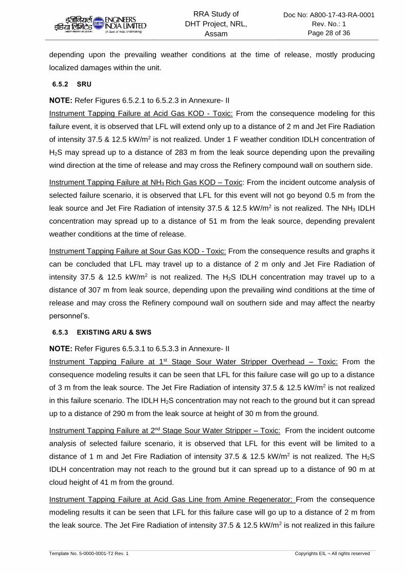
6.5.2 SRU
NOTE: Refer Figures 6.5.2.1 to 6.5.2.3 in Annexure- II
Instrument Tapping Failure at Acid Gas KOD - Toxic: From the consequence modeling for this
failure event, it is observed that LFL will extend only up to a distance of 2 m and Jet Fire Radiation
of intensity 37.5 & 12.5 kW/m2 is not realized. Under 1 F weather condition IDLH concentration of
H2S may spread up to a distance of 283 m from the leak source depending upon the prevailing
wind direction at the time of release and may cross the Refinery compound wall on southern side.
Instrument Tapping Failure at NH3 Rich Gas KOD – Toxic: From the incident outcome analysis of
selected failure scenario, it is observed that LFL for this event will not go beyond 0.5 m from the
leak source and Jet Fire Radiation of intensity 37.5 & 12.5 kW/m2 is not realized. The NH3 IDLH
concentration may spread up to a distance of 51 m from the leak source, depending prevalent
weather conditions at the time of release.
Instrument Tapping Failure at Sour Gas KOD - Toxic: From the consequence results and graphs it
can be concluded that LFL may travel up to a distance of 2 m only and Jet Fire Radiation of
intensity 37.5 & 12.5 kW/m2 is not realized. The H2S IDLH concentration may travel up to a
distance of 307 m from leak source, depending upon the prevailing wind conditions at the time of
release and may cross the Refinery compound wall on southern side and may affect the nearby
personnel’s.
6.5.3 EXISTING ARU & SWS
NOTE: Refer Figures 6.5.3.1 to 6.5.3.3 in Annexure- II
Instrument Tapping Failure at 1st Stage Sour Water Stripper Overhead – Toxic: From the
consequence modeling results it can be seen that LFL for this failure case will go up to a distance
of 3 m from the leak source. The Jet Fire Radiation of intensity 37.5 & 12.5 kW/m2 is not realized
in this failure scenario. The IDLH H2S concentration may not reach to the ground but it can spread
up to a distance of 290 m from the leak source at height of 30 m from the ground.
Instrument Tapping Failure at 2nd Stage Sour Water Stripper – Toxic: From the incident outcome
analysis of selected failure scenario, it is observed that LFL for this event will be limited to a
distance of 1 m and Jet Fire Radiation of intensity 37.5 & 12.5 kW/m2 is not realized. The H2S
IDLH concentration may not reach to the ground but it can spread up to a distance of 90 m at
cloud height of 41 m from the ground.
Instrument Tapping Failure at Acid Gas Line from Amine Regenerator: From the consequence
modeling results it can be seen that LFL for this failure case will go up to a distance of 2 m from
the leak source. The Jet Fire Radiation of intensity 37.5 & 12.5 kW/m2 is not realized in this failure

RRA Study of
DHT Project, NRL,
Assam
Doc No: A800-17-43-RA-0001
Rev. No.: 1
Page 29 of 36
Template No. 5-0000-0001-T2 Rev. 1 Copyrights EIL ¬ All rights reserved
scenario. The IDLH H2S concentration may not reach to the ground but it can spread up to a
distance of 145 m from the leak source at height of 32 m from the ground.
6.5.4 OFFSITES
6.5.4.1 Tank on Fire
NOTE: Refer Figures 6.5.4.1.1 in Annexure-II
DHDT Feed Tank on Fire: From the consequence results and graphs of the selected credible
scenario, it can be concluded that Pool Fire radiation intensity of 8 kW/m2 may not affect the
adjacent DHT Feed Tank. The Pool Fire radiation intensity of 32 kW/m2 is not realized in this
case.
6.5.4.2 2” Leak at Tank Manifold
NOTE: Refer Figures 6.5.4.2.1 in Annexure-II
2 inch Leak at DHDT Feed Tank Manifold: From the incident outcome analysis of the selected
failure scenario it is observed that LFL may be travelling up to a distance of 54 m. The Jet Fire
radiation intensity of 32 & 8 kW/m2 would extend up to a distance of 21 m & 16 m respectively.
The Pool Fire radiation intensity of 32 kW/m2 is not realized and 8 kW/m2 would extend up to a
distance of 85 m. The 5 & 3 psi blast overpressures travel up to a distance of 67 m & 74 m
respectively depending upon the location of the release.
6.5.4.3 Offsite Pump
NOTE: Refer Figures 6.5.4.3.1 in Annexure-II
Instrument Tapping Failure at DHT Feed Pumps: From the event outcome of the selected failure
scenario it can be observed that LFL may be extended up to a distance of 26 m. The Jet Fire
Radiation Intensity of 32 & 8 kW/m2 can extend up to a distance of 43 m & 57 m respectively &
may damage the vacuum distillate tanks. The Pool Fire Radiation Intensity of 32 kW/m2 is not
realized & 8 kW/m2 can extend up to a distance of 54 m and may affect the vacuum distillate tank.
The 5 & 3 psi blast wave may reach up to a distance of 28 m & 31 m respectively.
1
RRA Study of
DHT Project, NRL,
Assam
Doc No: A800-17-43-RA-0001
Rev. No.: 1
Page 30 of 36
Template No. 5-0000-0001-T2 Rev. 1 Copyrights EIL ¬ All rights reserved
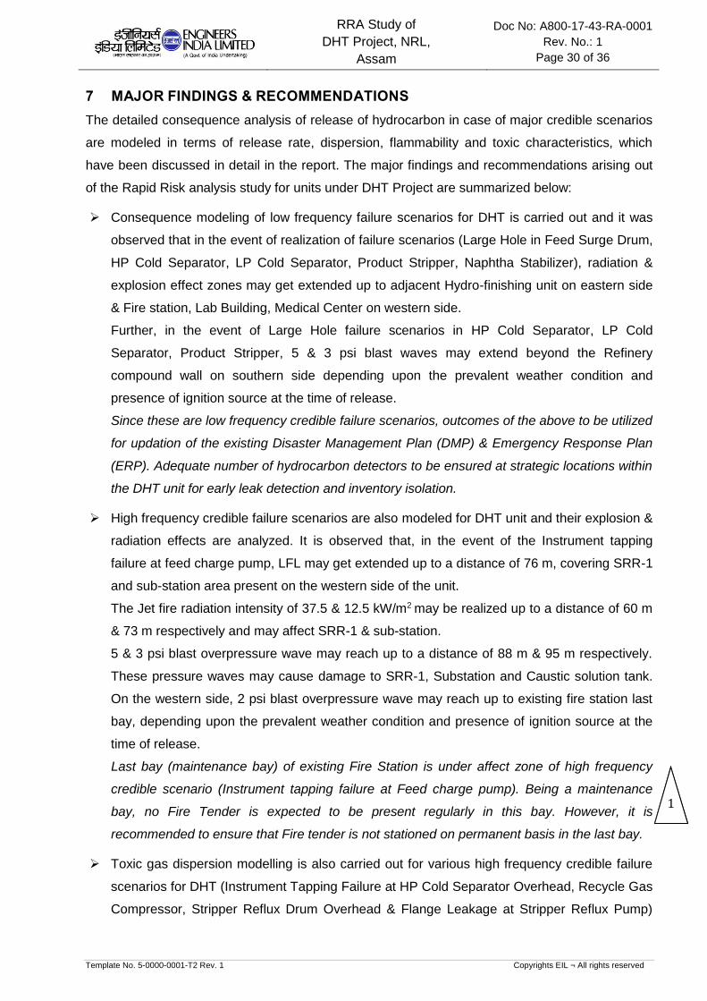
7 MAJOR FINDINGS & RECOMMENDATIONS
The detailed consequence analysis of release of hydrocarbon in case of major credible scenarios
are modeled in terms of release rate, dispersion, flammability and toxic characteristics, which
have been discussed in detail in the report. The major findings and recommendations arising out
of the Rapid Risk analysis study for units under DHT Project are summarized below:
Consequence modeling of low frequency failure scenarios for DHT is carried out and it was
observed that in the event of realization of failure scenarios (Large Hole in Feed Surge Drum,
HP Cold Separator, LP Cold Separator, Product Stripper, Naphtha Stabilizer), radiation &
explosion effect zones may get extended up to adjacent Hydro-finishing unit on eastern side
& Fire station, Lab Building, Medical Center on western side.
Further, in the event of Large Hole failure scenarios in HP Cold Separator, LP Cold
Separator, Product Stripper, 5 & 3 psi blast waves may extend beyond the Refinery
compound wall on southern side depending upon the prevalent weather condition and
presence of ignition source at the time of release.
Since these are low frequency credible failure scenarios, outcomes of the above to be utilized
for updation of the existing Disaster Management Plan (DMP) & Emergency Response Plan
(ERP). Adequate number of hydrocarbon detectors to be ensured at strategic locations within
the DHT unit for early leak detection and inventory isolation.
High frequency credible failure scenarios are also modeled for DHT unit and their explosion &
radiation effects are analyzed. It is observed that, in the event of the Instrument tapping
failure at feed charge pump, LFL may get extended up to a distance of 76 m, covering SRR-1
and sub-station area present on the western side of the unit.
The Jet fire radiation intensity of 37.5 & 12.5 kW/m2 may be realized up to a distance of 60 m
& 73 m respectively and may affect SRR-1 & sub-station.
5 & 3 psi blast overpressure wave may reach up to a distance of 88 m & 95 m respectively.
These pressure waves may cause damage to SRR-1, Substation and Caustic solution tank.
On the western side, 2 psi blast overpressure wave may reach up to existing fire station last
bay, depending upon the prevalent weather condition and presence of ignition source at the
time of release.
Last bay (maintenance bay) of existing Fire Station is under affect zone of high frequency
credible scenario (Instrument tapping failure at Feed charge pump). Being a maintenance
bay, no Fire Tender is expected to be present regularly in this bay. However, it is
recommended to ensure that Fire tender is not stationed on permanent basis in the last bay.
Toxic gas dispersion modelling is also carried out for various high frequency credible failure
scenarios for DHT (Instrument Tapping Failure at HP Cold Separator Overhead, Recycle Gas
Compressor, Stripper Reflux Drum Overhead & Flange Leakage at Stripper Reflux Pump)
1 1

RRA Study of
DHT Project, NRL,
Assam
Doc No: A800-17-43-RA-0001
Rev. No.: 1
Page 31 of 36
Template No. 5-0000-0001-T2 Rev. 1 Copyrights EIL ¬ All rights reserved
and it is observed that H2S IDLH hazard distance may extend beyond DHT unit battery limit.
However, the affect zone is confined within the Refinery Compound wall.
Hence, it is recommended to locate the toxic gas detectors within the DHT unit at strategic
locations and utilize the outcomes of these failure scenarios in the updation of the existing
Disaster Management Plan (DMP) & Emergency Response Plan (ERP).
Toxic gas credible failure scenarios are modeled for SRU. It is observed that in the event of
Instrument tapping failure at Acid Gas KOD & Sour Gas KOD under 1F weather condition,
H2S IDLH concentration may extend up to a distance of 283 m & 307 m respectively, from the
leak source, depending upon the prevailing wind conditions at the time of release. H2S IDLH
concentration may extend beyond the Refinery compound wall on southern side & may affect
the nearby personnel’s.
Hence, it is recommended to install toxic gas detectors within SRU at strategic locations and
utilize the outcome of these failure scenarios in the updation of the existing Disaster
Management Plan (DMP) & Emergency Response Plan (ERP). Moreover, due to close
proximity of another Sulphur Block, it is recommended to carry out Quantitative Risk Analysis
(QRA) of the refinery, so as to assess the effect of the H2S IDLH concentration in terms of
Individual & Societal Risk on the nearby buildings / Operator cabins / populations.
a) Recommendations for Construction Safety during execution of the DHT Project
Adequate barricading of the proposed unit to be done from existing running process units
during construction phase. Hydrocarbon / toxic detectors to be placed along the
barricading suitably to detect any hydrocarbon / toxic gas in vicinity of construction area.
Also, adequate firefighting & toxic gas handling arrangement are to be ensured in the
construction area. Ensure training of persons associated with construction activities for
response during fire & toxic gas release.
Proper material movement path within the Refinery shall be identified during the
construction phase of the project.
Detailed HSE Plan & HSE Philosophy to be developed by contractors during construction
phase of the project, in line with client’s safety requirements.
It is suggested to carry out HAZID, SIMOPS studies during pre-execution phase of the
DHT project to get a detailed overview of the possible hazards during construction phase
and action plan to prevent / mitigate the same.
b) General Recommendations
No operator cabin shall be located inside battery limits of proposed units under DHT
project. Also, operator cabin, if any located in the vicinity of unit shall be made of Blast
Resistant Construction with Positive Pressurization for protection of individuals inside
operator cabin from Explosion, Radiation & Toxic effects of various leak scenarios.

RRA Study of
DHT Project, NRL,
Assam
Doc No: A800-17-43-RA-0001
Rev. No.: 1
Page 32 of 36
Template No. 5-0000-0001-T2 Rev. 1 Copyrights EIL ¬ All rights reserved
Proper checking of contract people for smoking or inflammable materials to be ensured at
entry gates to avoid presence of any unidentified source of ignition.
Ensure vehicles entering the Refinery are fitted with spark arrestors, as a mandatory item.
In order to prevent secondary incident arising from any failure scenario, it is recommended
that sprinklers and other protective devices provided on the tanks are regularly checked to
ensure these are functional.
Mock drills to be organized at organization level to ensure preparation of the personnel’s
working in Refinery for handling any hazardous situation.
For positively pressurized building, both Hydrocarbon & Toxic detectors need to be placed
at suction duct of HVAC. HVAC to be tripped automatically in event of the detection of any
Hydrocarbon / toxic material by detector.
Ensure usage of safer oxidizing agents (Chlorine free) in Cooling Water circuit.
c) Mitigating Measures
Mitigating measures are those measures in place to minimize the loss of containment event and,
hazards arising out of Loss of containment. These include:
Early detection of an undesirable event (HC leak, Toxic gas leak, Flame etc.) and
development of subsequent quick isolation mechanism for major inventories.
Measures for controlling / minimization of Ignition sources inside the Refinery complex.
Active and Passive Fire Protection for critical equipment’s and major structures
Effective Emergency Response plans to be in place
d) Ignition Control
Ignition control will reduce the likelihood of fire events. This is the key for reducing the risk
within facilities processing flammable materials. As part of mitigation measure it strongly
recommended to consider minimization of the traffic movement within the Refinery.
e) Escape Routes
Ensure sufficient escape routes from the site are available to allow redundancy in escape
from all areas.
Ensure sufficient number of windsocks throughout the site to ensure visibility from all
locations. This will enable people to escape upwind or crosswind from flammable / toxic
releases.
Provide sign boards marking emergency/safe roads to be taken during any exigencies.
f) Preventive Maintenance for Critical Equipment’s
In order to reduce the failure frequency of critical equipment’s, the following are
recommended:
a. High head pumps and Compressors, which are in flammable / toxic services, are
needed to be identified.
i. Their seals, instruments and accessories are to be monitored closely
RRA Study of
DHT Project, NRL,
Assam
Doc No: A800-17-43-RA-0001
Rev. No.: 1
Page 33 of 36
Template No. 5-0000-0001-T2 Rev. 1 Copyrights EIL ¬ All rights reserved
ii. A detailed preventive maintenance plan to be prepared and followed.
b. Surge Drums & Reflux drums and high inventory vessels whose rupture may lead
to massive consequences are needed to be identified and following to be ensured:
i. Monitoring of vessel internals during shut down.
ii. A detailed preventive maintenance plan to be prepared and followed.
g) Others
Ensure removal of hammer blinds from the process facilities, if any.
Closed sampling system to be considered for pressurized services like LPG, Propylene
etc.
Recommended to use portable HC detector during sampling and maintenance etc.
Provide breathing apparatus at strategic locations inside Refinery.

RRA Study of
DHT Project, NRL,
Assam
Doc No: A800-17-43-RA-0001
Rev. No.: 1
Page 34 of 36
Template No. 5-0000-0001-T2 Rev. 1 Copyrights EIL ¬ All rights reserved
8 GLOSSARY
CASUALTY Someone who suffers serious injury or worse i.e. including fatal
injuries. As a rough guide fatalities are likely to be half the total
casualties. But this may vary depending on the nature of the event.
HAZARD A chemical or physical condition with the potential of causing
damage.
FLAMMABILITY LIMITS In fuel-air systems, a range of compositions exists inside which a
(UFL – LFL) flame will propagate substantial distance from an
ignition source. The limiting fuel concentrations are termed as
Upper flammability or explosives limit (Fuel concentrations
exceeding this are too rich) and Lower flammability or explosives
limit (Fuel concentrations below this are too lean).
FLASH FIRE The burning of a vapor cloud at very low flame propagation speed.
Combustion products are generated at a rate low enough for
expansion to take place easily without significant overpressure
ahead or behind the flame front. The hazard is therefore only due to
thermal effects.
OVERPRESSURE Maximum pressure above atmosphere pressure experiences during
the passage of a blast wave from an explosion expressed in this
report as pounds per square inch (psi).
EXPLOSION A rapid release of energy, which causes a pressure discontinuity or
shock wave moving away from the source. An explosion can be
produced by detonation of a high explosive or by the rapid burning
of a flammable gas cloud. The resulting overpressure is sufficient to
cause damage inside and outside the cloud as the shock wave
propagation into the atmosphere beyond the cloud. Some authors
use the term deflagration for this type of explosion
DOMINO EFFECT The effect that loss of containment of one installation leads to loss
of containment of other installations
EVENT TREE A logic diagram of success and failure combinations of events used
to identify accident sequences leading to all possible consequences
of a given initiating event.
TLV “Threshold limit value” is defined as the concentration of the
substance in air that can be breathed for five consecutive 8 hours
work day (40 hours work week) by most people without side effect.
STEL “Short Term Exposure Limit” is the maximum permissible average
exposure for the time period specified (15 minutes).
RRA Study of
DHT Project, NRL,
Assam
Doc No: A800-17-43-RA-0001
Rev. No.: 1
Page 35 of 36
Template No. 5-0000-0001-T2 Rev. 1 Copyrights EIL ¬ All rights reserved
IDLH “Immediate Dangerous to Life and Health” is the maximum
concentration level from which one could escape within 30 minutes
without any escape impairing symptoms.
PASQUILL CLASS Classification to qualify the stability of the atmosphere, indicated by
a letter ranging from A, for very unstable, to F, for stable.
FREQUENCY The number of times an outcome is expected to occur in a given
period of time.
RRA Study of
DHT Project, NRL,
Assam
Doc No: A800-17-43-RA-0001
Rev. No.: 1
Page 36 of 36
Template No. 5-0000-0001-T2 Rev. 1 Copyrights EIL ¬ All rights reserved
9 REFERENCES
1. Classification of hazardous locations, A. W. Cox, F. P. Lees and M. L. Ang, Published by
the Institute of Chemical engineers, U. K.
2. The reference manual, Volume-II, Creemer & Warner Ltd. U. K. (Presently Entec).
3. Risk analysis of six potentially hazardous industrial objects in the Rijnmond area; A pilot
study. A report to the Rijnmond Public Authority. D. Riedel publishing company, U. K.
4. Loss prevention in the process industries, Hazard identification, Assessment and Control,
Frank. P. Lees (Vol. I, II & III), Published by Butterworth-Heinemann, U. K.
5. AICHE, CCPS, Chemical process Quantitative Risk Analysis
6. Guideline for Quantitative Risk assessment, ‘Purple book’.

RRA Study of
DHT Project, NRL,
Assam
Doc No: A800-17-43-RA-0001
Rev. No.: 1
Page 1 of 4
Template No. 5-0000-0001-T2 Rev. 1 Copyrights EIL ¬ All rights reserved
ANNEXURE-I
CONSEQUENCE ANALYSIS HAZARD DISTANCES

Temp.
(OC)
Press.
(Kg/cm2g)4 KW/m2 12.5 KW/m2 37.5 KW/m2 4 KW/m2 12.5 KW/m2 37.5 KW/m2 2 psi 3 psi 5 psi
1 F 153 109 84 69 64 35 NR 203 188 174 -
2 D 107 104 78 63 71 35 NR 140 130 122 -
1 F 76 94 73 60 - - - 103 95 88 -
2 D 73 88 67 54 - - - 101 93 87 -
1 F 207 173 134 110 - - - 297 273 253 H2S - 61
2 D 211 158 120 98 - - - 296 275 257 H2S - 58
1 F 34 27 18 NR - - - 45 41 38 H2S - NR
2 D 30 27 19 NR - - - 32 29 27 H2S - NR
1 F 204 163 125 103 - - - 303 277 256 H2S - 63
2 D 209 150 113 92 - - - 286 265 247 H2S - 58
1 F 35 30 22 16 - - - 47 43 39 H2S - 13
2 D 30 30 23 17 - - - 45 42 38 H2S - 14
1 F 32 29 21 14 - - - 48 43 40 -
2 D 28 30 23 16 - - - 34 31 28 -
1 F 207 142 109 89 61 38 NR 281 261 244 -
2 D 212 137 102 82 68 41 NR 280 263 248 -
1 F 12 22 17 15 26 20 15 17 15 14 -
2 D 10 21 16 13 27 22 16 16 14 13 -
1 F 18 - - - - - - 70 55 42 -
2 D 20 - - - - - - 70 55 42 -
1 F 7 NR NR NR - - - - - - H2S - NR
2 D 7 NR NR NR - - - - - - H2S - NR
1 F 39 39 30 25 38 26 17 45 41 38 H2S - 107
2 D 33 37 28 23 37 27 17 43 40 37 H2S - 77
1 F 132 133 103 86 - - - 190 175 163 -
2 D 133 127 96 79 - - - 182 169 158 -
1 F 2 NR NR NR - - - - - - H2S - 283
2 D 2 NR NR NR - - - - - - H2S - 89
1 F 0.5 NR NR NR - - - - - - NH3 - 44
2 D 0.5 NR NR NR - - - - - - NH3 - 51
1 F 2 NR NR NR - - - - - - H2S - 307
2 D 2 NR NR NR - - - - - - H2S - 80
1 F 3 NR NR NR - - - - - - H2S - NR
2 D 3 NR NR NR - - - - - - H2S - NR
1 F 0.5 NR NR NR - - - - - - NH3 - NR
2 D 0.5 NR NR NR - - - - - - NH3 - NR
Blast Over Pressure (m)
WeathersFlash Fire
(m)Failure Case
0.06
Jet Fire (m)
0.8 0.1Instrument Tapping Failure - Toxic
Instrument Tapping Failure - Toxic
40
40
Large Hole on bottom outlet 166
Pool Fire (m)
1.5
55
124 83
Flange Leakage - Toxic
Existing SWS &
ARU
Ist Stage Sour Water Stripper
(08-CC-00-001)Instrument Tapping Failure - Toxic 84
3
IInd Stage Sour Water Stripper
(08-CC-00-002)90 0.7
Sour Gas KOD
1
2 Instrument Tapping Failure - Toxic
Instrument Tapping Failure - Toxic
EquipmentLeak Rate
Kg/sSl No.
Large Hole on bottom outlet - Toxic
Instrument Tapping Failure - Toxic
8
6
Unit
Feed Charge Pump
(21-PA-101 A/B)165 83
Large Hole on bottom outlet 248
HP Cold Separator Overhead
(21-VV-103)
Operating Conditions
83
Make-Up Gas Compressor 2nd Stage (21-
KA-102 A/B)
Feed Surge Drum (21-VV-102) 165
Instrument Tapping Failure
IDLH Conc
Distance
(m)
NOTE
Stripper Reflux Drum (21-VV-201) Catastrophic Rupture 40
1
2
3
18.2
21.5
7.9
4
5
1.5
38.6
Recycle Gas Compressor
(21-KA-101)
Large Hole on bottom outlet
Instrument Tapping Failure
1.2
12
35.6
HP Cold Separator (21-VV-103) 55 67.5 130.3
7.1
Large Hole on bottom outlet - Toxic
Instrument Tapping Failure - Toxic
7
Product Stripper (21-CC-201)
0.47.1
-
DHT
10
12.1 0.7
LP Cold Separator (21-VV-104) 56.8 36 95
67.5
82
1.3
Diesel Product Pump
(21-PA-202 A/B)Seal Failure9
13 Naphtha Stabilizer (21-CC-202)
2
2 NH3 Rich Gas KOD
11 40
7
84
248
Instrument Tapping Failure - Toxic 90
1
7.65
12
0.7 0.06
Acid Gas KOD
Stripper Reflux Pump
(21-PA-201 A/B)
Stripper Reflux Drum Overhead
(21-VV-201)
0.8
0.5
0.09
Numaligarh Refinery Ltd.- DHT Project Consequence Analysis Hazard Distances
SRU
Page 2 of 4

Temp.
(OC)
Press.
(Kg/cm2g)4 KW/m2 12.5 KW/m2 37.5 KW/m2 4 KW/m2 12.5 KW/m2 37.5 KW/m2 2 psi 3 psi 5 psi
Blast Over Pressure (m)
WeathersFlash Fire
(m)Failure Case
Jet Fire (m) Pool Fire (m)
1.5
EquipmentLeak Rate
Kg/sSl No.Unit
Operating Conditions
Feed Surge Drum (21-VV-102) 165
IDLH Conc
Distance
(m)
NOTE
1 18.2Large Hole on bottom outlet
DHT
Numaligarh Refinery Ltd.- DHT Project Consequence Analysis Hazard Distances
1 F 2 NR NR NR - - - - - - H2S - NR
2 D 2 NR NR NR - - - - - - H2S - NR
Existing SWS &
ARU
3
Acid Gas Line from Amine Regenerator
Column
(11-CC-00-002)
Instrument Tapping Failure - Toxic 113 0.95 0.1
Page 3 of 4

Temp.
(OC)
Press.
(Kg/cm2g)4 KW/m2 8 KW/m2 32 KW/m2 4 KW/m2 8 KW/m2 32 KW/m2 2 psi 3 psi 5 psi
1 F - - - - 36 22 NR - - -
2 D - - - - 41 26 NR - - -
1 F 54 25 21 16 132 85 NR 81 74 67
2 D 33 24 20 15 143 90 NR 49 45 41
1 F 22 65 55 43 66 48 NR 35 31 28
2 D 26 69 57 43 74 54 NR 34 31 28
8.43 DHT Feed Pump Instrument Tapping Failure 30 10.5
-
2 DHT Feed Tank 2" Leak in Manifold Amb. 0.9 15.9
1 DHT Feed Tank Tank On Fire Amb.
Offsite
Numaligarh Refinery Ltd. - DHT Project :Offsite Consequence Analysis Hazard Distances
Unit Sl No. Equipment Failure Case
Operating ConditionsLeak Rate
Kg/sWeathers
Flash Fire
(m)
Jet Fire (m) Pool Fire (m) Blast Over Pressure (m)
NOTE
Atm.
1
Page 4 of 4

RRA Study of
DHT Project, NRL,
Assam
Doc No: A800-17-43-RA-0001
Rev. No.: 1
Page 1 of 74
Template No. 5-0000-0001-T2 Rev. 1 Copyrights EIL ¬ All rights reserved
ANNEXURE-II
FIGURES FOR CONSEQUENCE ANALYSIS
1

Figure 6.5.1.1 A: DHT: Large Hole on bottom outlet of Feed Surge Drum; Flash Fire Distances (m)
Page 2 of 74
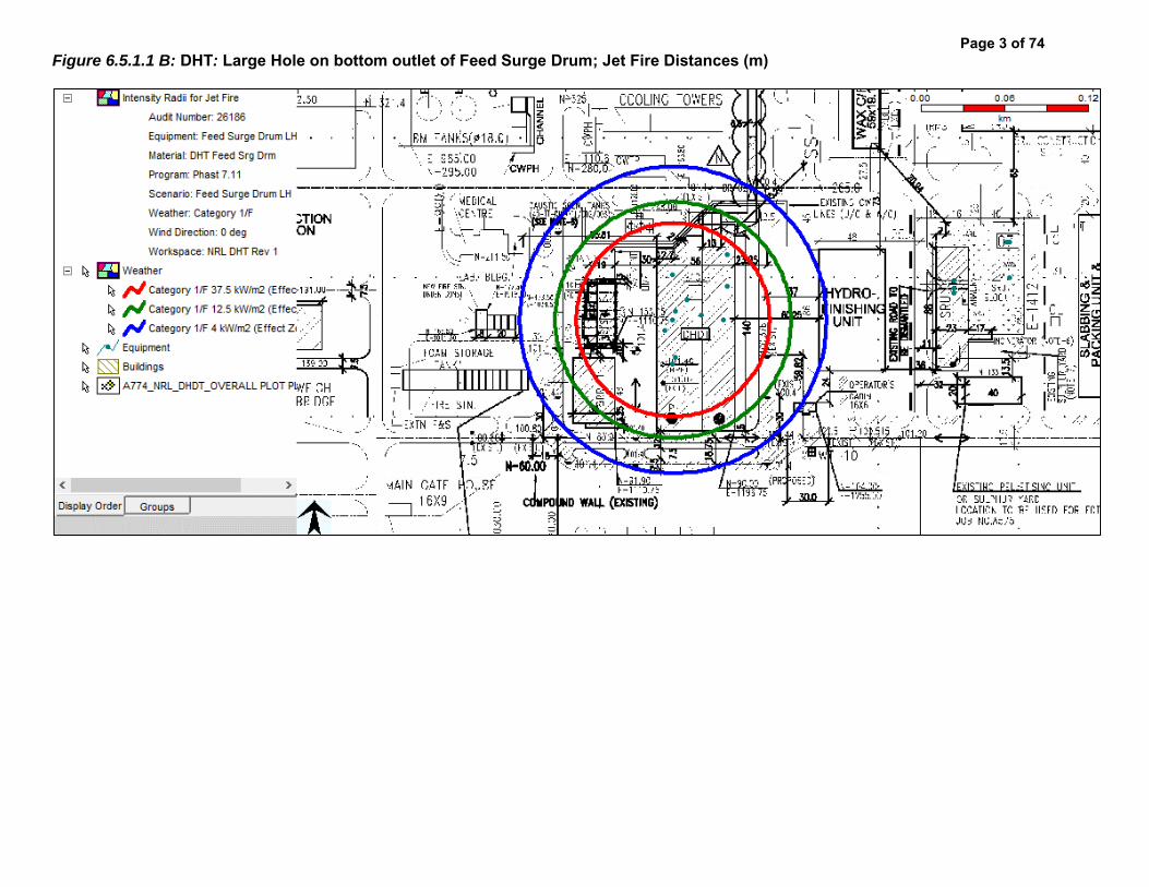
Figure 6.5.1.1 B: DHT: Large Hole on bottom outlet of Feed Surge Drum; Jet Fire Distances (m)
Page 3 of 74

Figure 6.5.1.1 C: DHT: Large Hole on bottom outlet of Feed Surge Drum; Over Pressure Distances (m)
Page 4 of 74

Figure 6.5.1.1 D: DHT: Large Hole on bottom outlet of Feed Surge Drum; Pool Fire Distances (m)
Page 5 of 74

Figure 6.5.1.2 A: DHT: Instrument Tapping Failure at Feed Charge Pump; Flash Fire Distances (m)
Page 6 of 74

Figure 6.5.1.2 B: DHT: Instrument Tapping Failure at Feed Charge Pump; Jet Fire Distances (m)
Page 7 of 74

Figure 6.5.1.2 C: DHT: Instrument Tapping Failure at Feed Charge Pump; Over Pressure Distances (m)
Page 8 of 74

Figure 6.5.1.3 A: DHT: Large Hole on bottom outlet of HP Cold Separator; Flash Fire Distances (m)
Page 9 of 74

Figure 6.5.1.3 B: DHT: Large Hole on bottom outlet of HP Cold Separator; Jet Fire Distances (m)
Page 10 of 74
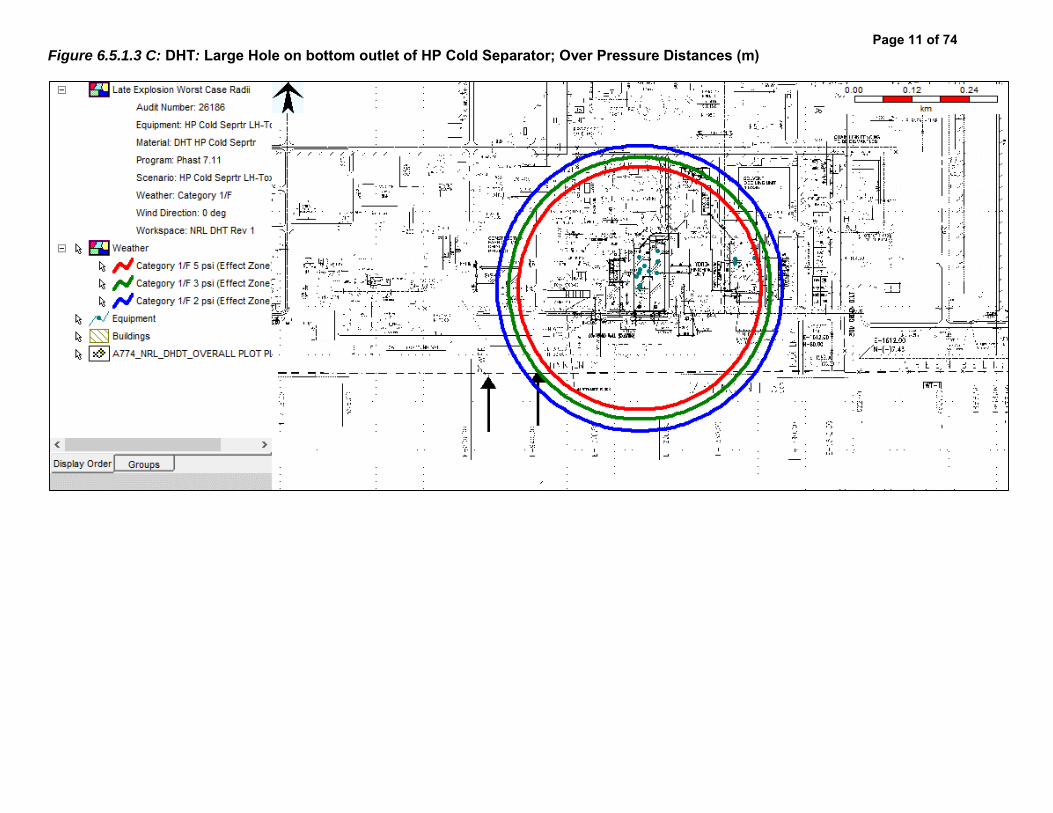
Figure 6.5.1.3 C: DHT: Large Hole on bottom outlet of HP Cold Separator; Over Pressure Distances (m)
Page 11 of 74

Figure 6.5.1.3 D: DHT: Large Hole on bottom outlet of HP Cold Separator; H2S IDLH Hazard Distances (m)
Page 12 of 74

Figure 6.5.1.3 E: DHT: Large Hole on bottom outlet of HP Cold Separator; H2S IDLH Hazard Distances (m)
Page 13 of 74

Figure 6.5.1.4 A: DHT: Instrument Tapping Failure at HP Cold Separator Overhead; Flash Fire Distances (m)
Page 14 of 74

Figure 6.5.1.4 B: DHT: Instrument Tapping Failure at HP Cold Separator Overhead; Jet Fire Distances (m)
Page 15 of 74

Figure 6.5.1.4 C: DHT: Instrument Tapping Failure at HP Cold Separator Overhead; Over Pressure Distances (m)
Page 16 of 74

Figure 6.5.1.4 D: DHT: Instrument Tapping Failure at Cold HP Separator Overhead; H2S IDLH Hazard Distances (m)
Page 17 of 74

Figure 6.5.1.5 A: DHT: Large Hole on bottom outlet of LP Cold Separator; Flash Fire Distances (m)
Page 18 of 74

Figure 6.5.1.5 B: DHT: Large Hole on bottom outlet of LP Cold Separator; Jet Fire Distances (m)
Page 19 of 74
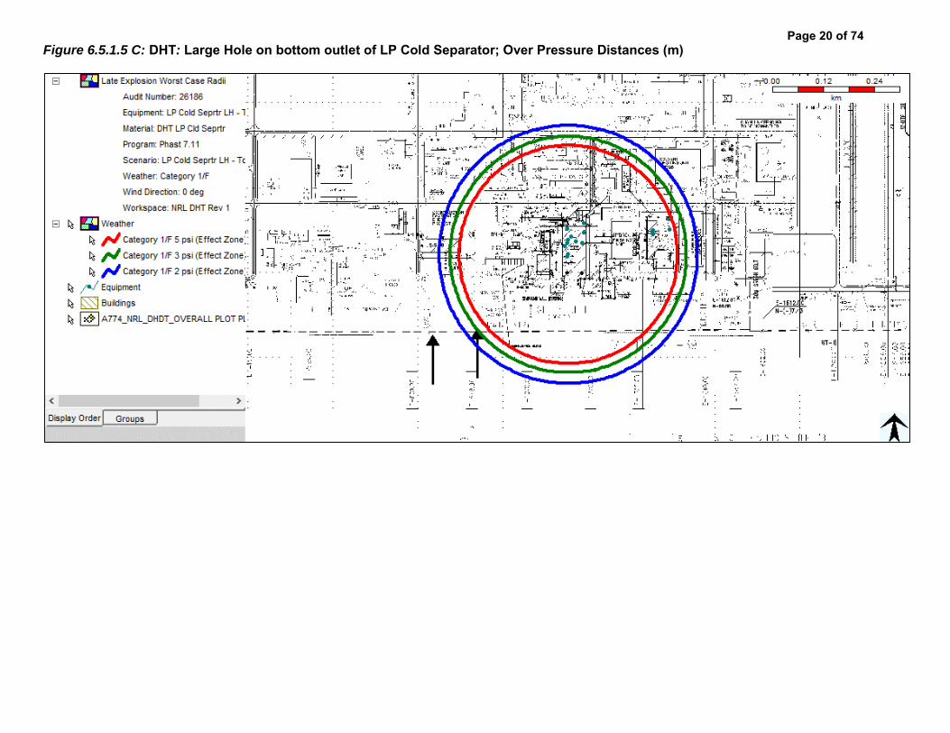
Figure 6.5.1.5 C: DHT: Large Hole on bottom outlet of LP Cold Separator; Over Pressure Distances (m)
Page 20 of 74

Figure 6.5.1.5 D: DHT: Large Hole on bottom outlet of LP Cold Separator; H2S IDLH Hazard Distances (m)
Page 21 of 74

Figure 6.5.1.5 E: DHT: Large Hole on bottom outlet of LP Cold Separator; H2S IDLH Hazard Distances (m)
Page 22 of 74

Figure 6.5.1.6 A: DHT: Instrument Tapping Failure at Recycle Gas Compressor; Flash Fire Distances (m)
Page 23 of 74
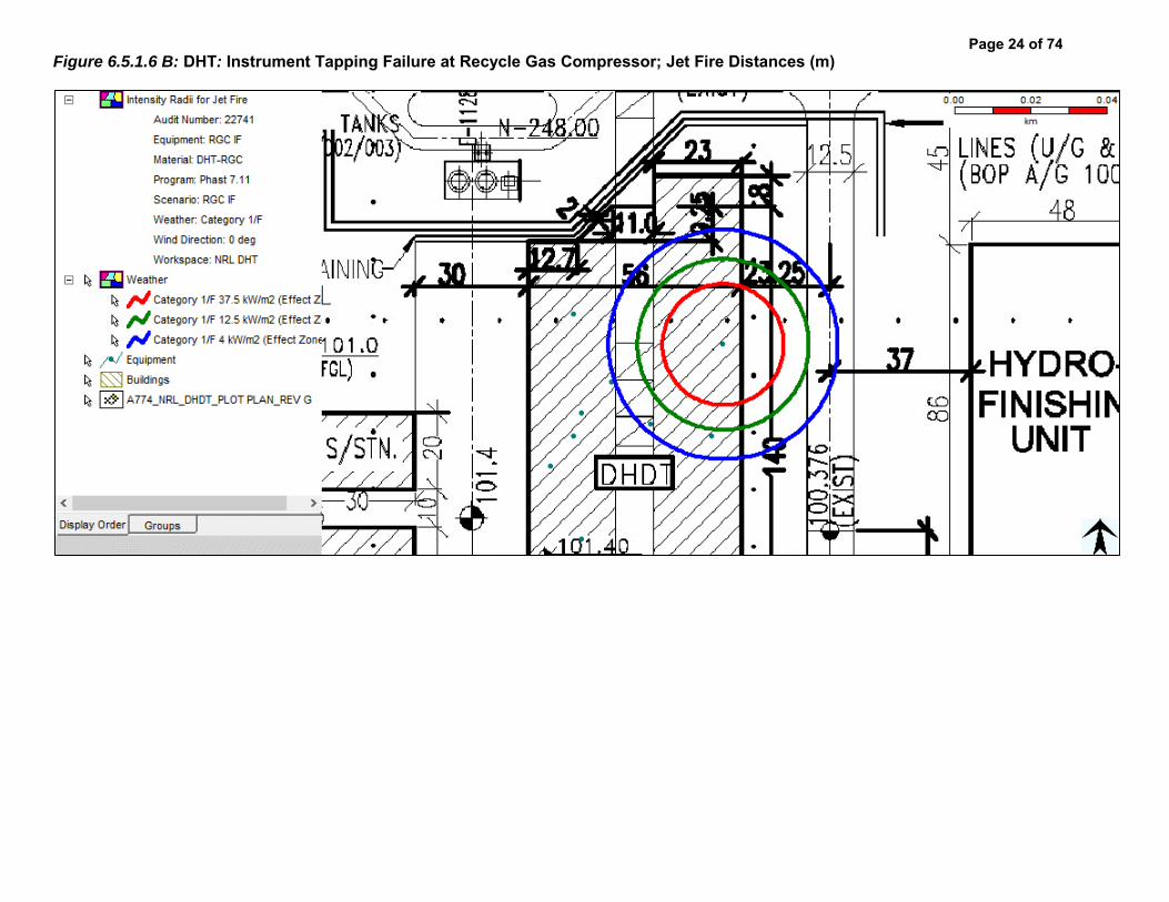
Figure 6.5.1.6 B: DHT: Instrument Tapping Failure at Recycle Gas Compressor; Jet Fire Distances (m)
Page 24 of 74

Figure 6.5.1.6 C: DHT: Instrument Tapping Failure at Recycle Gas Compressor; Over Pressure Distances (m)
Page 25 of 74

Figure 6.5.1.6 D: DHT: Instrument Tapping Failure at Recycle Gas Compressor; H2S IDLH Hazard Distances (m)
Page 26 of 74

Figure 6.5.1.7 A: DHT: Instrument Tapping Failure at Make-up Gas Compressor 2nd Stage; Flash Fire Distances (m)
Page 27 of 74

Figure 6.5.1.7 B: DHT: Instrument Tapping Failure at Make-up Gas Compressor 2nd Stage; Jet Fire Distances (m)
Page 28 of 74

Figure 6.5.1.7 C: DHT: Instrument Tapping Failure at Make-up Gas Compressor 2nd Stage; Over Pressure Distances (m)
Page 29 of 74

Figure 6.5.1.8 A: DHT: Large Hole on bottom outlet of Product Stripper; Flash Fire Distances (m)
Page 30 of 74

Figure 6.5.1.8 B: DHT: Large Hole on bottom outlet of Product Stripper; Jet Fire Distances (m)
Page 31 of 74

Figure 6.5.1.8 C: DHT: Large Hole on bottom outlet of Product Stripper; Over Pressure Distances (m)
Page 32 of 74

Figure 6.5.1.8 D: DHT: Large Hole on bottom outlet of Product Stripper; Pool Fire Distances (m)
Page 33 of 74

Figure 6.5.1.9 A: DHT: Seal Failure at Diesel Product Pump; Flash Fire Distances (m)
Page 34 of 74
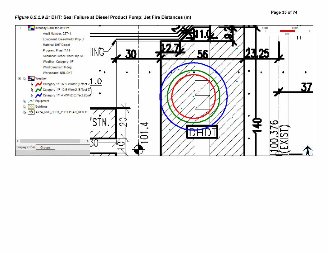
Figure 6.5.1.9 B: DHT: Seal Failure at Diesel Product Pump; Jet Fire Distances (m)
Page 35 of 74

Figure 6.5.1.9 C: DHT: Seal Failure at Diesel Product Pump; Overpressure Fire Distances (m)
Page 36 of 74

Figure 6.5.1.9 D: DHT: Seal Failure at Diesel Product Pump; Pool Fire Distances (m)
Page 37 of 74

Figure 6.5.1.10 A: DHT: Catastrophic Rupture of Stripper Reflux Drum; Flash Fire Distances (m)
Page 38 of 74

Figure 6.5.1.10 B: DHT: Catastrophic Rupture of Stripper Reflux Drum; Overpressure Distances (m)
Page 39 of 74

Figure 6.5.1.11 A: DHT: Instrument Tapping Failure at Stripper Reflux Drum Overhead; Flash Fire Distances (m)
Page 40 of 74

Figure 6.5.1.11 B: DHT: Instrument Tapping Failure at Stripper Reflux Drum Overhead; H2S IDLH Hazard Distances (m)
Page 41 of 74

Figure 6.5.1.12 A: DHT: Flange Leakage at Stripper Reflux Pump; Flash Fire Distances (m)
Page 42 of 74

Figure 6.5.1.12 B: DHT: Flange Leakage at Stripper Reflux Pump; Jet Fire Distances (m)
Page 43 of 74

Figure 6.5.1.12 C: DHT: Flange Leakage at Stripper Reflux Pump; Over Pressure Distances (m)
Page 44 of 74

Figure 6.5.1.12 D: DHT: Flange Leakage at Stripper Reflux Pump; Pool Fire Distances (m)
Page 45 of 74

Figure 6.5.1.12 E: DHT: Flange Leakage at Stripper Reflux Pump; H2S IDLH Hazard Distances (m)
Page 46 of 74

Figure 6.5.1.12 F: DHT: Flange Leakage at Stripper Reflux Pump; H2S IDLH Hazard Distances (m)
Page 47 of 74

Figure 6.5.1.13 A: DHT: Large Hole on the Bottom Outlet of Naphtha Stabilizer; Flash Fire Distances (m)
Page 48 of 74
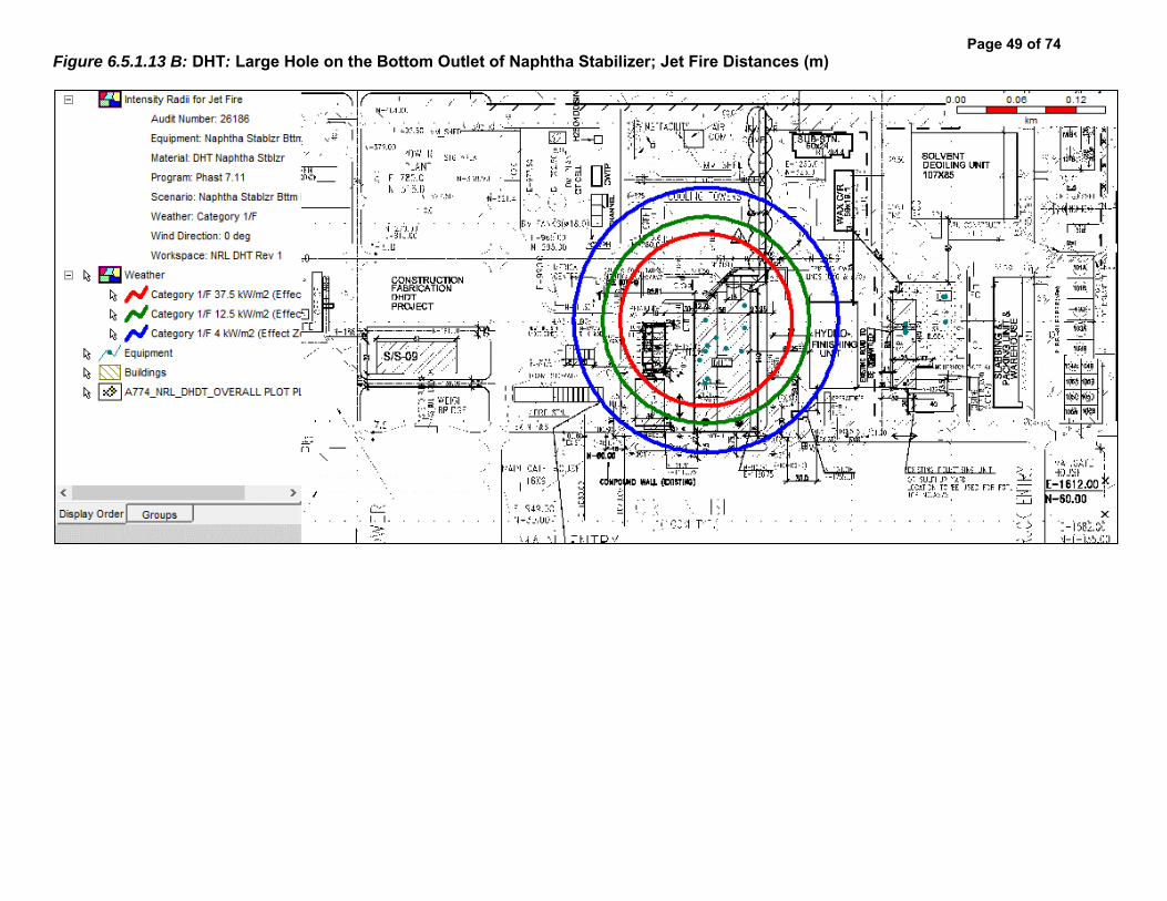
Figure 6.5.1.13 B: DHT: Large Hole on the Bottom Outlet of Naphtha Stabilizer; Jet Fire Distances (m)
Page 49 of 74

Figure 6.5.1.13 C: DHT: Large Hole on the Bottom Outlet of Naphtha Stabilizer; Overpressure Fire Distances (m)
Page 50 of 74

Figure 6.5.2.1 A: SRU: Instrument Tapping Failure at Acid Gas KO Drum; Flash Fire Distances (m)
Page 51 of 74

Figure 6.5.2.1 B: SRU: Instrument Tapping Failure at Acid Gas KO Drum; H2S IDLH Hazard Distances (m)
Page 52 of 74

Figure 6.5.2.1 C: SRU: Instrument Tapping Failure at Acid Gas KO Drum; H2S IDLH Hazard Distances (m)
Page 53 of 74

Figure 6.5.2.2 A: SRU: Instrument Tapping Failure at NH3 Rich Gas KO Drum; Flash Fire Distances (m)
Page 54 of 74

Figure 6.5.2.2 B: SRU: Instrument Tapping Failure at NH3 Rich Gas KO Drum; H2S IDLH Hazard Distances (m)
Page 55 of 74

Figure 6.5.2.2 C: SRU: Instrument Tapping Failure at NH3 Rich Gas KO Drum; H2S IDLH Hazard Distances (m)
Page 56 of 74

Figure 6.5.2.3 A: SRU: Instrument Tapping Failure at Sour Gas KO Drum; Flash Fire Distances (m)
Page 57 of 74

Figure 6.5.2.3 B: SRU: Instrument Tapping Failure at Sour Gas KO Drum; H2S IDLH Hazard Distances (m)
Page 58 of 74

Figure 6.5.2.3 C: SRU: Instrument Tapping Failure at Sour Gas KO Drum; H2S IDLH Hazard Distances (m)
Page 59 of 74
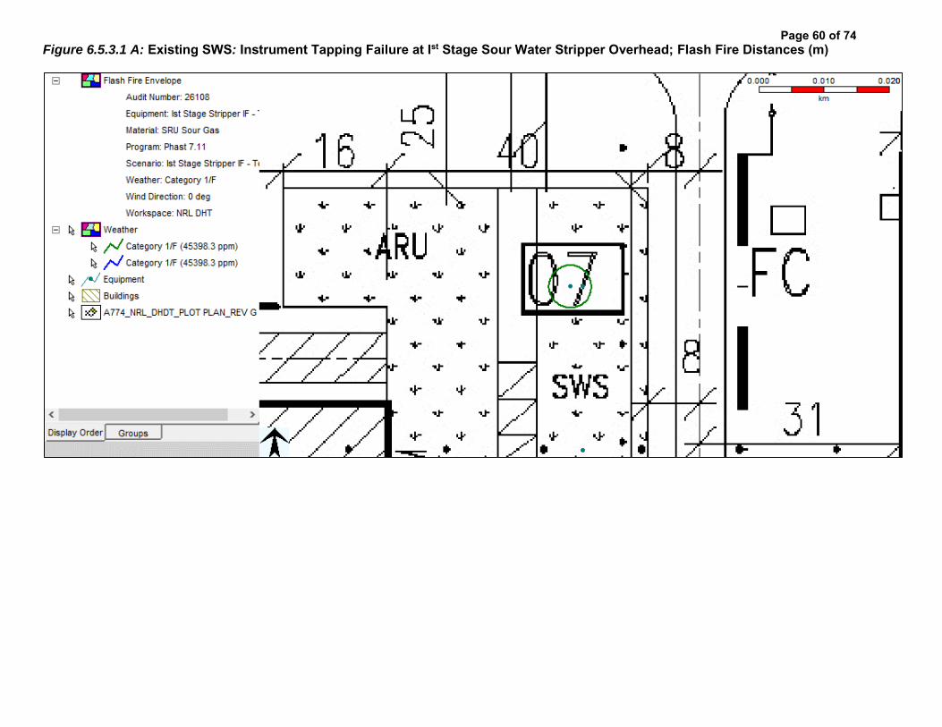
Figure 6.5.3.1 A: Existing SWS: Instrument Tapping Failure at Ist Stage Sour Water Stripper Overhead; Flash Fire Distances (m)
Page 60 of 74

Figure 6.5.3.1 B: Existing SWS: Instrument Tapping Failure at Ist Stage Sour Water Stripper Overhead; H2S IDLH Hazard Distances (m)
Page 61 of 74
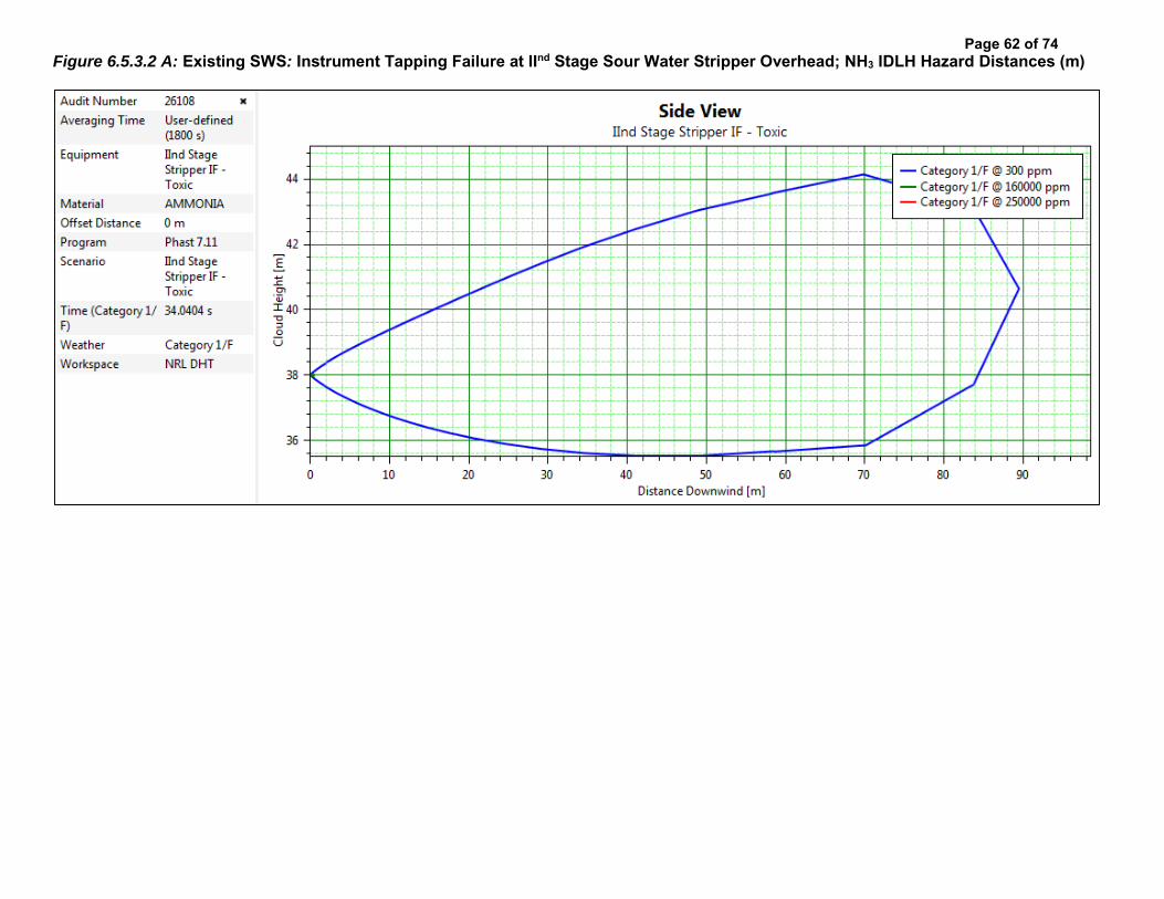
Figure 6.5.3.2 A: Existing SWS: Instrument Tapping Failure at IInd Stage Sour Water Stripper Overhead; NH3 IDLH Hazard Distances (m)
Page 62 of 74

Figure 6.5.3.3 A: Existing ARU: Instrument Tapping Failure at Acid Gas Line from Amine Regenerator; Flash Fire Distances (m)
Page 63 of 74

Figure 6.5.3.3 B: Existing ARU: Instrument Tapping Failure at Acid Gas Line from Amine Regenerator; H2S IDLH Hazard Distances (m)
Page 64 of 74
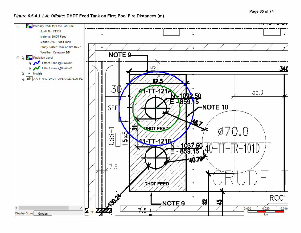
Figure 6.5.4.1.1 A: Offsite: DHDT Feed Tank on Fire; Pool Fire Distances (m)
Page 65 of 74

Figure 6.5.4.1.1 B: Offsite: DHDT Feed Tank on Fire; Pool Fire Distances (m)
Page 66 of 74

Figure 6.5.4.2.1 A: Offsite: 2 inch Leak at DHDT Feed Tank; Flash Fire Distances (m)
Page 67 of 74
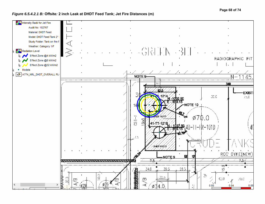
Figure 6.5.4.2.1 B: Offsite: 2 inch Leak at DHDT Feed Tank; Jet Fire Distances (m)
Page 68 of 74

Figure 6.5.4.2.1 C: Offsite: 2 inch Leak at DHDT Feed Tank; Over Pressure Distances (m)
Page 69 of 74
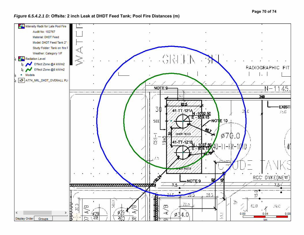
Figure 6.5.4.2.1 D: Offsite: 2 inch Leak at DHDT Feed Tank; Pool Fire Distances (m)
Page 70 of 74

Figure 6.5.4.3.1 A: Offsite: Instrument Tapping Failure at DHT Feed Pump; Flash Fire Distances (m)
Page 71 of 74

Figure 6.5.4.3.1 B: Offsite: Instrument Tapping Failure at DHT Feed Pump; Jet Fire Distances (m)
Page 72 of 74

Figure 6.5.4.3.1 C: Offsite: Instrument Tapping Failure at DHT Feed Pump; Overpressure Distances (m)
Page 73 of 74

Figure 6.5.4.3.1 D: Offsite: Instrument Tapping Failure at DHT Feed Pump; Pool Fire Distances (m)
Page 74 of 74
RRA Study of
LPG Mounded Bullets &
Upgradation of LPG Bottling
Plant, NRL- Assam
Doc No: A816-17-43-RA-0001
Rev. No.: 0
Page 2 of 28
Template No. 5-0000-0001-T2 Rev. 1 Copyrights EIL ¬ All rights reserved
PREFACE
Numaligarh Refinery Limited, (NRL) presently operates a 3 MMTPA refinery at Numaligarh,
District Golaghat, Assam. NRL is planning to implement a project of installing 4 nos. LPG
mounded bullets and upgradation of the existing LPG Bottling Plant.
Engineers India Limited (EIL), New Delhi, has been entrusted by M/s Numaligarh Refinery
Limited, Assam (NRL) as an EIA consultant for this Project. As a part of the project, RRA is being
carried out for the facilities
Rapid Risk Analysis study identifies the hazards associated with the facility, analyses the
consequences, draws suitable conclusions and provides necessary recommendations to mitigate
the hazard/ risk.
This Rapid Risk Analysis study is based on the information made available at the time of this
study and EIL’s own data source for similar plants. EIL has exercised all reasonable skill, care
and diligence in carrying out the study. However, this report is not deemed to be any undertaking,
warrantee or certificate.

RRA Study of
LPG Mounded Bullets &
Upgradation of LPG Bottling
Plant, NRL- Assam
Doc No: A816-17-43-RA-0001
Rev. No.: 0
Page 3 of 28
Template No. 5-0000-0001-T2 Rev. 1 Copyrights EIL ¬ All rights reserved
TABLE OF CONTENTS
1 EXECUTIVE SUMMARY ....................................................................................................... 5
1.1 INTRODUCTION ............................................................................................................ 5
1.2 APPROACH METHODOLOGY ....................................................................................... 5
1.3 MAJOR FINDINGS AND RECOMMENDATIONS ........................................................... 5
2 INTRODCUTION ................................................................................................................... 9
2.1 STUDY AIMS AND OBJECTIVE ..................................................................................... 9
2.2 SCOPE OF WORK ......................................................................................................... 9
3 SITE CONDITION ................................................................................................................ 10
3.1 GENERAL .................................................................................................................... 10
3.2 SITE, LOCATION AND VICINITY ................................................................................. 10
3.3 METEOROLOGICAL CONDITIONS ............................................................................. 10
4 HAZARDS ASSOCIATED WITH THE FACILITIES .............................................................. 14
4.1 GENERAL .................................................................................................................... 14
4.2 HAZARDS ASSOCIATED WITH FLAMMABLE MATERIALS........................................ 14
4.2.1 LIQUIFIED PETROLEUM GAS .............................................................................. 14
5 HAZARD IDENTIFICATION ................................................................................................. 15
5.1 GENERAL .................................................................................................................... 15
5.2 MODES OF FAILURE ................................................................................................... 15
5.3 SELECTED FAILURE CASES ...................................................................................... 16
6 CONSEQUENCE ANALYSIS ............................................................................................... 18
6.1 GENERAL .................................................................................................................... 18
6.2 CONSEQUENCE ANALYSIS MODELLING .................................................................. 18
6.2.1 DISCHARGE RATE ............................................................................................... 18
6.2.2 DISPERSION ......................................................................................................... 18
6.2.3 FLASH FIRE .......................................................................................................... 18
6.2.4 JET FIRE ............................................................................................................... 19
6.2.5 POOL FIRE ........................................................................................................... 19
6.2.6 VAPOR CLOUD EXPLOSION ............................................................................... 19

RRA Study of
LPG Mounded Bullets &
Upgradation of LPG Bottling
Plant, NRL- Assam
Doc No: A816-17-43-RA-0001
Rev. No.: 0
Page 4 of 28
Template No. 5-0000-0001-T2 Rev. 1 Copyrights EIL ¬ All rights reserved
6.3 SIZE AND DURATION OF RELEASE ........................................................................... 19
6.4 DAMAGE CRITERIA ..................................................................................................... 20
6.4.1 LFL OR FLASH FIRE ............................................................................................. 20
6.4.2 THERMAL HAZARD DUE TO POOL FIRE, JET FIRE AND FIRE BALL ................ 20
6.4.3 VAPOR CLOUD EXPLOSION ............................................................................... 20
6.5 CONSEQUENCE ANALYSIS FOR UNITS.................................................................... 21
6.5.1 LPG Mounded Bullet .............................................................................................. 21
6.5.2 LPG Bottling Plant ................................................................................................. 22
7 MAJOR FINDINGS & RECOMMENDATIONS ..................................................................... 23
8 GLOSSARY ......................................................................................................................... 26
9 REFERENCES .................................................................................................................... 28
ANNEXURE-I: CONSEQUENCE ANALYSIS HAZARD DISTANCES
ANNEXURE-II: FIGURES FOR CONSEQUENCE ANALYSIS
LIST OF TABLES
Table 1: New Proposed Facilities under Project ............................................................................ 9
Table 2: Existing Facilities under Project ....................................................................................... 9
Table 3: Atmospheric Parameter ................................................................................................. 11
Table 4: Average Mean Wind Speed (m/s) .................................................................................. 11
Table 5: % Number of Days Wind From ...................................................................................... 11
Table 6: Pasquill Stability Classes ............................................................................................... 12
Table 7: Weather Conditions ....................................................................................................... 13
Table 8: Hazardous Properties of LPG ........................................................................................ 14
Table 9: Size of Release ............................................................................................................. 19
Table 10: Damage Due to Incident Thermal Radiation Intensity .................................................. 20
Table 11: Damage Effects of Blast Overpressure ........................................................................ 21
LIST OF FIGURES
Figure 1: NRL Site ...................................................................................................................... 10
RRA Study of
LPG Mounded Bullets &
Upgradation of LPG Bottling
Plant, NRL- Assam
Doc No: A816-17-43-RA-0001
Rev. No.: 0
Page 5 of 28
Template No. 5-0000-0001-T2 Rev. 1 Copyrights EIL ¬ All rights reserved
1 EXECUTIVE SUMMARY
1.1 INTRODUCTION
NRL, a subsidiary of M/s Bharat Petroleum Corporation Limited presently operates a 3.0 MMTPA
refinery at Numaligarh, Golaghat, Assam. The Refinery presently produces Euro-III and part Euro-
IV grade HSD. NRL is planning to implement a project of installing 4 nos. LPG mounded bullets
and upgradation of the existing LPG Bottling Plant.
The project envisages construction of 4 nos. of LPG mounded bullets of capacity 1760.56 m3
(1000MT) each and upon successful completion / construction of mounded bullets, existing 03
nos. of LPG Spheres and 01 LPG bullet will be dismantled up to ground level.
NRL has been also operating a LPG bottling plant adjacent to its Refinery location at Numaligarh,
Assam since the year 2002 and producing packed LPG getting distributed to retail consumers
through Oil marketing Companies. The proposed Upgradation of LPG bottling plant would
envisage replacement of the old semi-automatic system by a fully automatic electronic system.
The total capacity of the upgraded plant will be 42000 MT per annum along with improved safety
efficiency performance as against 10000 MT per annum existing plant.
EIL has been selected as an EIA consultant for the Project. As a part of the project Rapid Risk
Analysis Study of the facilities under scope of Project is being carried out.
This executive summary covers major findings arising out of the Rapid Risk Analysis study and
recommendations for the facilities under this Project. The detailed analysis is given in Section –6.
1.2 APPROACH METHODOLOGY
RRA study evaluates the consequences of potential failure scenarios, assess extent of damages,
based on damage criteria’s and suggest suitable measures for mitigating the Hazard.
RRA involves identification of various potential hazards & credible failure scenarios for various
units and other facilities including off-site storages & pumping, etc., based on their frequency of
occurrence & resulting consequence. Basically two types of scenarios are identified spanning
across various process facilities; Cases with high chance of occurrence but having low
consequence, e.g., Instrument Tapping Failure and cases with low chance of occurrence but
having high consequence, e.g., Catastrophic Rupture of Pressure Vessels / Large Hole on the
outlet of Pressure Vessels. Effect zones for various outcomes of failure scenarios (Flash Fire, Jet
Fire, Pool Fire, Blast overpressure, toxic release, etc.) are studied and identified in terms of
distances on plot plan. Based on effect zones, measures for mitigation of the hazard/risk are
suggested.
1.3 MAJOR FINDINGS AND RECOMMENDATIONS
The detailed consequence analysis of release of hydrocarbon in case of major credible scenarios
are modeled in terms of release rate, dispersion, flammability and toxic characteristics, which

RRA Study of
LPG Mounded Bullets &
Upgradation of LPG Bottling
Plant, NRL- Assam
Doc No: A816-17-43-RA-0001
Rev. No.: 0
Page 6 of 28
Template No. 5-0000-0001-T2 Rev. 1 Copyrights EIL ¬ All rights reserved
have been discussed in detail in the report. The major findings and recommendations arising out
of the Rapid Risk analysis study for facilities under Project are summarized below:
Consequence modeling of failure scenarios for LPG Mounded Bullets & associated pumping
system are modelled & studied. It is observed that in the event of realization of 20 & 10 mm
leak scenarios for LPG transfer pumps of Gantry & Bottling Plant, radiation & explosion effect
zones may be limited to leak vicinities, depending upon the prevalent weather condition &
ignition sources encountered at the time of the release and may not affect any nearby
facilities.
Adequate number of hydrocarbon detectors to be ensured at strategic locations within the
LPG pump house for early leak detection and inventory isolation and suitable sprinklers
system as per OISD requirements. It is recommended that road on northern, western &
eastern side of the LPG pump house to be classified for traffic movement.
Consequence failure modeling of leak scenarios in LPG Bottling Plant is carried out &
studied. In the event of realization of 20 & 10 mm leak scenarios in the LPG line inside
Bottling Plant, radiation & explosion effect zones may engulf & affect the whole LPG Bottling
plant, depending upon the location of the release, prevalent weather condition & ignition
sources encountered at the time of the release and may affect the personnel’s working inside
the LPG Bottling Plant.
It is recommended to ensure the hydrocarbon & fire detectors inside the Bottling Plant at
appropriate locations and suitable active/passive fire protection measures inside the Bottling
Plant. These scenarios to be also used for updation of existing Disaster Management Plan &
Emergency Response Procedures.
In the event of fire scenario inside LPG Bottling Plant, the escalation effects need to be
evaluated further, as projectiles from LPG cylinder bursting may affect & damage the other
nearby facilities / buildings in the radius of the 460 m.
a) Recommendations for Construction Safety during execution of the Project
Adequate barricading of the proposed facilities to be done from existing running facilities
during construction phase. Hydrocarbon detectors to be placed along the barricading
suitably to detect any hydrocarbon gas in vicinity of construction area.
Also, adequate firefighting & toxic gas handling arrangement are to be ensured in the
construction area. Ensure training of persons associated with construction activities for
response during fire.
Proper material movement path within the Refinery shall be identified during the
construction phase of the project.
Detailed HSE Plan & HSE Philosophy to be developed by contractors during construction
phase of the project, in line with client’s safety requirements.

RRA Study of
LPG Mounded Bullets &
Upgradation of LPG Bottling
Plant, NRL- Assam
Doc No: A816-17-43-RA-0001
Rev. No.: 0
Page 7 of 28
Template No. 5-0000-0001-T2 Rev. 1 Copyrights EIL ¬ All rights reserved
It is suggested to carry out HAZID, SIMOPS studies during pre-execution phase of the
project to get a detailed overview of the possible hazards during construction phase and
action plan to prevent / mitigate the same.
b) General Recommendations
No operator cabin shall be located in the vicinity of the LPG Mounded Bullet Pump House
and LPG Bottling Plant.
Proper checking of contract people for smoking or inflammable materials to be ensured at
entry gates to avoid presence of any unidentified source of ignition.
Ensure vehicles entering the Refinery are fitted with spark arrestors, as a mandatory item.
In order to prevent secondary incident arising from any failure scenario, it is recommended
that sprinklers and other protective devices provided on the tanks are regularly checked to
ensure these are functional.
Mock drills to be organized at organization level to ensure preparation of the personnel’s
working in Refinery for handling any hazardous situation.
For positively pressurized building, both Hydrocarbon & Toxic detectors need to be placed
at suction duct of HVAC. HVAC to be tripped automatically in event of the detection of any
Hydrocarbon / toxic material by detector.
c) Mitigating Measures
Mitigating measures are those measures in place to minimize the loss of containment event and,
hazards arising out of Loss of containment. These include:
Early detection of an undesirable event (HC leak, Toxic gas leak, Flame etc.) and
development of subsequent quick isolation mechanism for major inventories.
Active and Passive Fire Protection for critical equipment’s and major structures
Effective Emergency Response plans to be in place
d) Ignition Control
Ignition control will reduce the likelihood of fire events. This is the key for reducing the risk
within facilities processing flammable materials. As part of mitigation measure it is strongly
recommended to consider minimization of the traffic movement within the Refinery.
e) Escape Routes
Ensure sufficient escape routes from the site are available to allow redundancy in escape
from all areas.
Ensure sufficient number of windsocks throughout the site to ensure visibility from all
locations. This will enable people to escape upwind or crosswind from flammable / toxic
releases.
Provide sign boards marking emergency/safe roads to be taken during any exigencies.

RRA Study of
LPG Mounded Bullets &
Upgradation of LPG Bottling
Plant, NRL- Assam
Doc No: A816-17-43-RA-0001
Rev. No.: 0
Page 8 of 28
Template No. 5-0000-0001-T2 Rev. 1 Copyrights EIL ¬ All rights reserved
f) Preventive Maintenance for Critical Equipment’s
In order to reduce the failure frequency of critical equipment’s, the following are
recommended:
a. High head pumps and Compressors, which are in flammable / toxic services, are
needed to be identified.
i. Their seals, instruments and accessories are to be monitored closely
ii. A detailed preventive maintenance plan to be prepared and followed.
g) Others
Ensure removal of hammer blinds from the process facilities, if any.
Closed sampling system to be considered for pressurized services like LPG, Propylene
etc.
Recommended to use portable HC detector during sampling and maintenance etc.

RRA Study of
LPG Mounded Bullets &
Upgradation of LPG Bottling
Plant, NRL- Assam
Doc No: A816-17-43-RA-0001
Rev. No.: 0
Page 9 of 28
Template No. 5-0000-0001-T2 Rev. 1 Copyrights EIL ¬ All rights reserved
2 INTRODCUTION
2.1 STUDY AIMS AND OBJECTIVE
The objectives of the Rapid Risk Analysis study are to identify and quantify all potential failure
modes that may lead to hazardous consequences and extent. Typical hazardous consequences
include fire, explosion and toxic releases.
The Rapid Risk analysis will also identify potential hazardous consequences having impacts on
population and property in the vicinity of the facilities, and provides information necessary in
developing strategies to prevent accidents and formulate the Disaster Management Plan.
The Rapid Risk Analysis includes the following steps:
a) Identification of failure cases within the process and off-site facilities
b) Evaluate process hazards emanating from the identified potential accident scenarios.
c) Analyze the damage effects to surroundings due to such incidents.
d) Suggest mitigating measures to reduce the hazard / risk.
The Risk analysis study has been carried out using the risk assessment software program
‘PHAST ver. 7.11 developed by DNV Technica.
2.2 SCOPE OF WORK
The study addresses the hazards that can be realized due to operations associated with the
proposed facilities under Project. It covers the following facilities of Refinery:
Table 1: New Proposed Facilities under Project
S. No. Description Remarks
1. LPG Mounded Bullets 4 nos.
Table 2: Existing Facilities under Project
S. No. Description Remarks
1. Upgradation of LPG Bottling Plant
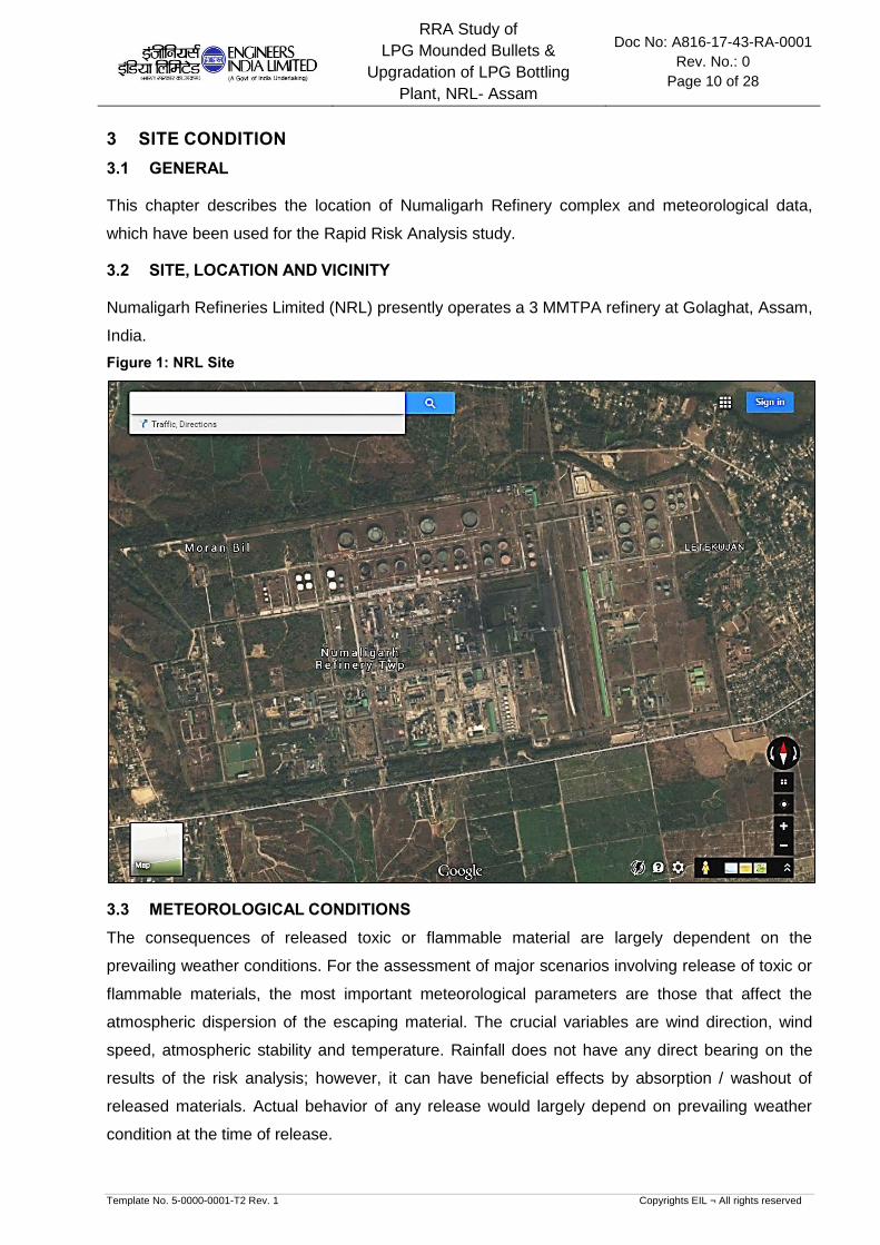
RRA Study of
LPG Mounded Bullets &
Upgradation of LPG Bottling
Plant, NRL- Assam
Doc No: A816-17-43-RA-0001
Rev. No.: 0
Page 10 of 28
Template No. 5-0000-0001-T2 Rev. 1 Copyrights EIL ¬ All rights reserved
3 SITE CONDITION
3.1 GENERAL
This chapter describes the location of Numaligarh Refinery complex and meteorological data,
which have been used for the Rapid Risk Analysis study.
3.2 SITE, LOCATION AND VICINITY
Numaligarh Refineries Limited (NRL) presently operates a 3 MMTPA refinery at Golaghat, Assam,
India.
Figure 1: NRL Site
3.3 METEOROLOGICAL CONDITIONS
The consequences of released toxic or flammable material are largely dependent on the
prevailing weather conditions. For the assessment of major scenarios involving release of toxic or
flammable materials, the most important meteorological parameters are those that affect the
atmospheric dispersion of the escaping material. The crucial variables are wind direction, wind
speed, atmospheric stability and temperature. Rainfall does not have any direct bearing on the
results of the risk analysis; however, it can have beneficial effects by absorption / washout of
released materials. Actual behavior of any release would largely depend on prevailing weather
condition at the time of release.
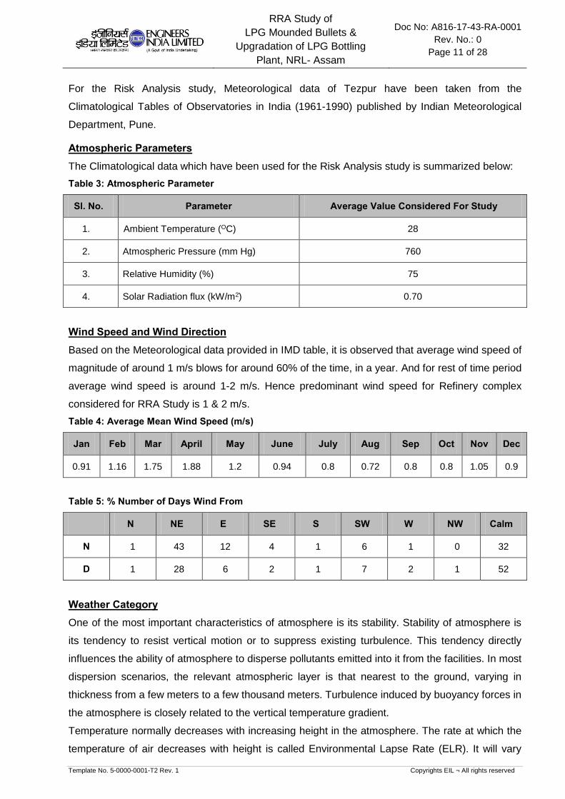
RRA Study of
LPG Mounded Bullets &
Upgradation of LPG Bottling
Plant, NRL- Assam
Doc No: A816-17-43-RA-0001
Rev. No.: 0
Page 11 of 28
Template No. 5-0000-0001-T2 Rev. 1 Copyrights EIL ¬ All rights reserved
For the Risk Analysis study, Meteorological data of Tezpur have been taken from the
Climatological Tables of Observatories in India (1961-1990) published by Indian Meteorological
Department, Pune.
Atmospheric Parameters
The Climatological data which have been used for the Risk Analysis study is summarized below:
Table 3: Atmospheric Parameter
Sl. No. Parameter Average Value Considered For Study
1. Ambient Temperature (OC) 28
2. Atmospheric Pressure (mm Hg) 760
3. Relative Humidity (%) 75
4. Solar Radiation flux (kW/m2) 0.70
Wind Speed and Wind Direction
Based on the Meteorological data provided in IMD table, it is observed that average wind speed of
magnitude of around 1 m/s blows for around 60% of the time, in a year. And for rest of time period
average wind speed is around 1-2 m/s. Hence predominant wind speed for Refinery complex
considered for RRA Study is 1 & 2 m/s.
Table 4: Average Mean Wind Speed (m/s)
Jan Feb Mar April May June July Aug Sep Oct Nov Dec
0.91 1.16 1.75 1.88 1.2 0.94 0.8 0.72 0.8 0.8 1.05 0.9
Table 5: % Number of Days Wind From
N NE E SE S SW W NW Calm
N 1 43 12 4 1 6 1 0 32
D 1 28 6 2 1 7 2 1 52
Weather Category
One of the most important characteristics of atmosphere is its stability. Stability of atmosphere is
its tendency to resist vertical motion or to suppress existing turbulence. This tendency directly
influences the ability of atmosphere to disperse pollutants emitted into it from the facilities. In most
dispersion scenarios, the relevant atmospheric layer is that nearest to the ground, varying in
thickness from a few meters to a few thousand meters. Turbulence induced by buoyancy forces in
the atmosphere is closely related to the vertical temperature gradient.
Temperature normally decreases with increasing height in the atmosphere. The rate at which the
temperature of air decreases with height is called Environmental Lapse Rate (ELR). It will vary

RRA Study of
LPG Mounded Bullets &
Upgradation of LPG Bottling
Plant, NRL- Assam
Doc No: A816-17-43-RA-0001
Rev. No.: 0
Page 12 of 28
Template No. 5-0000-0001-T2 Rev. 1 Copyrights EIL ¬ All rights reserved
from time to time and from place to place. The atmosphere is said to be stable, neutral or unstable
according to ELR is less than, equal to or greater than Dry Adiabatic Lapse Rate (DALR), which is
a constant value of 0.98°C/100 meters.
Pasquill stability parameter, based on Pasquill – Gifford categorization, is such a meteorological
parameter, which decreases the stability of atmosphere, i.e., the degree of convective turbulence.
Pasquill has defined six stability classes ranging from `A' (extremely unstable) to `F' (stable). Wind
speeds, intensity of solar radiation (daytime insulation) and nighttime sky cover have been
identified as prime factors defining these stability categories. Below Table indicates the various
Pasquill stability classes.
Table 6: Pasquill Stability Classes
Surface Wind Speed
(meter/s)
Day time solar radiation Night time cloud cover
Strong Medium Slight Thin < 3/8 Medium 3/8 Overcast >4/5
< 2 A A – B B - - D
2 – 3 A – B B C E F D
3 – 5 B B – C C D E D
5 – 6 C C – D D D D D
> 6 C D D D D D
Legend: A = Very unstable, B = Unstable, C = Moderately unstable, D = Neutral, E = Moderately
stable, F = stable
When the atmosphere is unstable and wind speeds are moderate or high or gusty, rapid
dispersion of pollutants will occur. Under these conditions, pollutant concentrations in air will be
moderate or low and the material will be dispersed rapidly. When the atmosphere is stable and
wind speed is low, dispersion of material will be limited and pollutant concentration in air will be
high. In general worst dispersion conditions (i.e. contributing to greater hazard distances) occur
during low wind speed and very stable weather conditions, such as that at 1F weather condition
(i.e. 1 m/s wind speed and Pasquill Stability F).
Stability category for the present study is identified based on the cloud amount and wind speed.
For risk analysis the representative average annual weather conditions are assessed based on
the following:
Average Wind speed in order of 1 m/s would be experienced for more than 60% of time in a year
and Wind speed of 1-2 m/s can be realized in the month of Feb to May. Based on weather
analysis, predominant weather stability of “F”& “D” was selected with wind speed 1 m/s & 2 m/s
for consequence analysis, respectively.
The consequence results are reported in tabular form for all the weather conditions and are
represented graphically for worst weather condition.

RRA Study of
LPG Mounded Bullets &
Upgradation of LPG Bottling
Plant, NRL- Assam
Doc No: A816-17-43-RA-0001
Rev. No.: 0
Page 13 of 28
Template No. 5-0000-0001-T2 Rev. 1 Copyrights EIL ¬ All rights reserved
Table 7: Weather Conditions
Wind Speed Pasquill Stability
1 F
2 D
Note: For RRA Study Plot Plan (Doc. No.: A774-000-17-44-0001 Rev R) has been used.
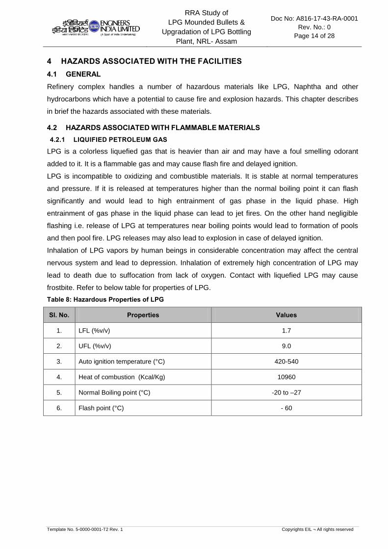
RRA Study of
LPG Mounded Bullets &
Upgradation of LPG Bottling
Plant, NRL- Assam
Doc No: A816-17-43-RA-0001
Rev. No.: 0
Page 14 of 28
Template No. 5-0000-0001-T2 Rev. 1 Copyrights EIL ¬ All rights reserved
4 HAZARDS ASSOCIATED WITH THE FACILITIES
4.1 GENERAL
Refinery complex handles a number of hazardous materials like LPG, Naphtha and other
hydrocarbons which have a potential to cause fire and explosion hazards. This chapter describes
in brief the hazards associated with these materials.
4.2 HAZARDS ASSOCIATED WITH FLAMMABLE MATERIALS
4.2.1 LIQUIFIED PETROLEUM GAS
LPG is a colorless liquefied gas that is heavier than air and may have a foul smelling odorant
added to it. It is a flammable gas and may cause flash fire and delayed ignition.
LPG is incompatible to oxidizing and combustible materials. It is stable at normal temperatures
and pressure. If it is released at temperatures higher than the normal boiling point it can flash
significantly and would lead to high entrainment of gas phase in the liquid phase. High
entrainment of gas phase in the liquid phase can lead to jet fires. On the other hand negligible
flashing i.e. release of LPG at temperatures near boiling points would lead to formation of pools
and then pool fire. LPG releases may also lead to explosion in case of delayed ignition.
Inhalation of LPG vapors by human beings in considerable concentration may affect the central
nervous system and lead to depression. Inhalation of extremely high concentration of LPG may
lead to death due to suffocation from lack of oxygen. Contact with liquefied LPG may cause
frostbite. Refer to below table for properties of LPG.
Table 8: Hazardous Properties of LPG
Sl. No. Properties Values
1. LFL (%v/v) 1.7
2. UFL (%v/v) 9.0
3. Auto ignition temperature (°C) 420-540
4. Heat of combustion (Kcal/Kg) 10960
5. Normal Boiling point (°C) -20 to –27
6. Flash point (°C) - 60

RRA Study of
LPG Mounded Bullets &
Upgradation of LPG Bottling
Plant, NRL- Assam
Doc No: A816-17-43-RA-0001
Rev. No.: 0
Page 15 of 28
Template No. 5-0000-0001-T2 Rev. 1 Copyrights EIL ¬ All rights reserved
5 HAZARD IDENTIFICATION
5.1 GENERAL
A classical definition of hazard states that hazard is in fact the characteristic of
system/plant/process that presents potential for an accident. Hence all the components of a
system/plant/process need to be thoroughly examined in order to assess their potential for
initiating or propagating an unplanned event/sequence of events, which can be termed as an
accident.
In Risk Analysis terminology a hazard is something with the potential to cause harm. Hence the
Hazard Identification step is an exercise that seeks to identify what can go wrong at the major
hazard installation or process in such a way that people may be harmed. The output of this step is
a list of events that need to be passed on to later steps for further analysis.
The potential hazards posed by the facility were identified based on the past accidents, lessons
learnt and a checklist. This list includes the following elements.
Catastrophic Rupture of Pressure vessel
Large hole on outlet of process vessel
“Guillotine-Breakage” of pipe-work
Small hole, cracks or small bore failure (i.e. instrument tapping failure, drains/vents failure
etc.) in piping and vessels.
Flange leaks.
Storage Tank on fire
Leaks from pump glands and similar seals.
5.2 MODES OF FAILURE
There are various potential sources of large leakage, which may release hazardous chemicals
and hydrocarbon materials into the atmosphere. These could be in form of gasket failure in
flanged joints, bleeder valve left open inadvertently, an instrument tubing giving way, pump seal
failure, guillotine failure of equipment/ pipeline or any other source of leakage. Operating
experience can identify lots of these sources and their modes of failure. A list of general
equipment and pipeline failure mechanisms is as follows:
Material/Construction Defects
Incorrect selection or supply of materials of construction
Incorrect use of design codes
Weld failures
Failure of inadequate pipeline supports
Pre-Operational Failures
Failure induced during delivery at site
Failure induced during installation

RRA Study of
LPG Mounded Bullets &
Upgradation of LPG Bottling
Plant, NRL- Assam
Doc No: A816-17-43-RA-0001
Rev. No.: 0
Page 16 of 28
Template No. 5-0000-0001-T2 Rev. 1 Copyrights EIL ¬ All rights reserved
Pressure and temperature effects
Overpressure
Temperature expansion/contraction (improper stress analysis and support design)
Low temperature brittle fracture (if metallurgy is incorrect)
Fatigue loading (cycling and mechanical vibration)
Corrosion Failures
Internal corrosion (e.g. ingress of moisture)
External corrosion
Cladding/insulation failure (e.g. ingress of moisture)
Cathodic protection failure, if provided
Failures due to Operational Errors
Human error
Failure to inspect regularly and identify any defects
External Impact Induced Failures
Dropped objects
Impact from transport such as construction traffic
Vandalism
Subsidence
Strong winds
Failure due to Fire
External fire impinging on pipeline or equipment
Rapid vaporization of cold liquid in contact with hot surfaces
5.3 SELECTED FAILURE CASES
A list of selected failure cases was prepared based on process knowledge, engineering judgment,
experience, past incidents associated with such facilities and considering the general
mechanisms for loss of containment. A list of cases has been identified for the consequence
analysis study based on the following.
Cases with high chance of occurrence but having low consequence: Example of such
failure cases includes seal failure for pumps, instrument tapping failure, etc. The
consequence results will provide enough data for planning routine safety exercises. This
will emphasize the area where operator's vigilance is essential.
Cases with low chance of occurrence but having high consequence (The example includes
Large hole on the outlet of pressure vessels, Catastrophic Rupture of Pressure Vessels,
etc.)
This approach ensures at least one representative case of all possible types of accidental
failure events, is considered for the consequence analysis. Moreover, the list below

RRA Study of
LPG Mounded Bullets &
Upgradation of LPG Bottling
Plant, NRL- Assam
Doc No: A816-17-43-RA-0001
Rev. No.: 0
Page 17 of 28
Template No. 5-0000-0001-T2 Rev. 1 Copyrights EIL ¬ All rights reserved
includes at least one accidental case comprising of release of different sorts of highly
hazardous materials handled in the refinery. Although the list does not give complete failure
incidents considering all equipment’s, units, but the consequence of a similar incident
considered in the list below could be used to foresee the consequence of that particular
accident.
For selected credible failure scenarios and likely consequences for facilities of Numaligarh
Refinery under LPG Mounded Bullets & upgradation of LPG Bottling Plant Project, refer
Section-6.

RRA Study of
LPG Mounded Bullets &
Upgradation of LPG Bottling
Plant, NRL- Assam
Doc No: A816-17-43-RA-0001
Rev. No.: 0
Page 18 of 28
Template No. 5-0000-0001-T2 Rev. 1 Copyrights EIL ¬ All rights reserved
6 CONSEQUENCE ANALYSIS
6.1 GENERAL
Consequence analysis involves the application of the mathematical, analytical and computer
models for calculation of the effects and damages subsequent to a hydrocarbon / toxic release
accident.
Computer models are used to predict the physical behavior of hazardous incidents. The model
uses below mentioned techniques to assess the consequences of identified scenarios:
Modeling of discharge rates when holes develop in process equipment/pipe work
Modeling of the size & shape of the flammable/toxic gas clouds from releases in the
atmosphere
Modeling of the flame and radiation field of the releases that are ignited and burn as jet fire,
pool fire and flash fire
Modeling of the explosion fields of releases which are ignited away from the point of release
The different consequences (Flash fire, pool fire, jet fire and Explosion effects) of loss of
containment accidents depend on the sequence of events & properties of material released
leading to the either toxic vapor dispersion, fire or explosion or both.
6.2 CONSEQUENCE ANALYSIS MODELLING
6.2.1 DISCHARGE RATE
The initial rate of release through a leak depends mainly on the pressure inside the equipment,
size of the hole and phase of the release (liquid, gas or two-phase). The release rate decreases
with time as the equipment depressurizes. This reduction depends mainly on the inventory and
the action taken to isolate the leak and blow-down the equipment.
6.2.2 DISPERSION
Releases of gas into the open air form clouds whose dispersion is governed by the wind, by
turbulence around the site, the density of the gas and initial momentum of the release. In case of
flammable materials the sizes of these gas clouds above their Lower Flammable Limit (LFL) are
important in determining whether the release will ignite. In this study, the results of dispersion
modeling for flammable materials are presented LFL quantity.
6.2.3 FLASH FIRE
A flash fire occurs when a cloud of vapors/gas burns without generating any significant
overpressure. The cloud is typically ignited on its edge, remote from- the leak source. The
combustion zone moves through the cloud away from the ignition point. The duration of the flash
fire is relatively short but it may stabilize as a continuous jet fire from the leak source. For flash
fires, an approximate estimate for the extent of the total effect zone is the area over which the
cloud is above the LFL.
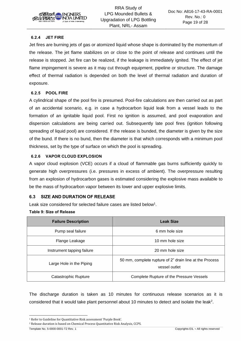
RRA Study of
LPG Mounded Bullets &
Upgradation of LPG Bottling
Plant, NRL- Assam
Doc No: A816-17-43-RA-0001
Rev. No.: 0
Page 19 of 28
Template No. 5-0000-0001-T2 Rev. 1 Copyrights EIL ¬ All rights reserved
6.2.4 JET FIRE
Jet fires are burning jets of gas or atomized liquid whose shape is dominated by the momentum of
the release. The jet flame stabilizes on or close to the point of release and continues until the
release is stopped. Jet fire can be realized, if the leakage is immediately ignited. The effect of jet
flame impingement is severe as it may cut through equipment, pipeline or structure. The damage
effect of thermal radiation is depended on both the level of thermal radiation and duration of
exposure.
6.2.5 POOL FIRE
A cylindrical shape of the pool fire is presumed. Pool-fire calculations are then carried out as part
of an accidental scenario, e.g. in case a hydrocarbon liquid leak from a vessel leads to the
formation of an ignitable liquid pool. First no ignition is assumed, and pool evaporation and
dispersion calculations are being carried out. Subsequently late pool fires (ignition following
spreading of liquid pool) are considered. If the release is bunded, the diameter is given by the size
of the bund. If there is no bund, then the diameter is that which corresponds with a minimum pool
thickness, set by the type of surface on which the pool is spreading.
6.2.6 VAPOR CLOUD EXPLOSION
A vapor cloud explosion (VCE) occurs if a cloud of flammable gas burns sufficiently quickly to
generate high overpressures (i.e. pressures in excess of ambient). The overpressure resulting
from an explosion of hydrocarbon gases is estimated considering the explosive mass available to
be the mass of hydrocarbon vapor between its lower and upper explosive limits.
6.3 SIZE AND DURATION OF RELEASE
Leak size considered for selected failure cases are listed below1.
Table 9: Size of Release
Failure Description Leak Size
Pump seal failure 6 mm hole size
Flange Leakage 10 mm hole size
Instrument tapping failure 20 mm hole size
Large Hole in the Piping 50 mm, complete rupture of 2” drain line at the Process
vessel outlet
Catastrophic Rupture Complete Rupture of the Pressure Vessels
The discharge duration is taken as 10 minutes for continuous release scenarios as it is
considered that it would take plant personnel about 10 minutes to detect and isolate the leak2.
1 Refer to Guideline for Quantitative Risk assessment ‘Purple Book’. 2 Release duration is based on Chemical Process Quantitative Risk Analysis, CCPS.

RRA Study of
LPG Mounded Bullets &
Upgradation of LPG Bottling
Plant, NRL- Assam
Doc No: A816-17-43-RA-0001
Rev. No.: 0
Page 20 of 28
Template No. 5-0000-0001-T2 Rev. 1 Copyrights EIL ¬ All rights reserved
6.4 DAMAGE CRITERIA
In order to appreciate the damage effect produced by various scenarios, physiological/physical
effects of the blast wave, thermal radiation or toxic vapor exposition are discussed.
6.4.1 LFL OR FLASH FIRE
Hydrocarbon vapor released accidentally will spread out in the direction of wind. If a source of
ignition finds an ignition source before being dispersed below lower flammability limit (LFL), a
flash fire is likely to occur and the flame will travel back to the source of leak. Any person caught
in the flash fire is likely to suffer fatal burn injury. Therefore, in consequence analysis, the distance
of LFL value is usually taken to indicate the area, which may be affected by the flash fire.
Flash fire (LFL) events are considered to cause direct harm to the population present within the
flammability range of the cloud. Fire escalation from flash fire such that process or storage
equipment or building may be affected is considered unlikely.
6.4.2 THERMAL HAZARD DUE TO POOL FIRE, JET FIRE AND FIRE BALL
Thermal radiation due to pool fire, jet fire or fire ball may cause various degrees of burn on human
body and process equipment. The damage effect due to thermal radiation intensity is tabulated
below.
Table 10: Damage Due to Incident Thermal Radiation Intensity
Incident Radiation Intensity
(Kw/M²) Type of Damage
37.5 Sufficient to cause damage to process equipment
32.0 Maximum flux level for thermally protected tanks containing flammable
liquid
12.5 Minimum energy required for piloted ignition of wood, melting of plastic
tubing etc.
8.0 Maximum heat flux for un-insulated tanks
4.0 Sufficient to cause pain to personnel if unable to reach cover within 20
seconds. However blistering of skin (1stdegree burns) is likely.
The hazard distances to the 32 kW/m2, 8 kW/m2 and 4 kW/m2 radiation levels, selected based on
their effect on population, buildings and equipment were modeled using PHAST.
6.4.3 VAPOR CLOUD EXPLOSION
In the event of explosion taking place within the plant, the resultant blast wave will have damaging
effects on equipment, structures, building and piping falling within the overpressure distances of
the blast. Tanks, buildings, structures etc. can only tolerate low level of overpressure. Human
body, by comparison, can withstand higher overpressure. But injury or fatality can be inflicted by
collapse of building of structures. The damage effect of blast overpressure is tabulated below.

RRA Study of
LPG Mounded Bullets &
Upgradation of LPG Bottling
Plant, NRL- Assam
Doc No: A816-17-43-RA-0001
Rev. No.: 0
Page 21 of 28
Template No. 5-0000-0001-T2 Rev. 1 Copyrights EIL ¬ All rights reserved
Table 11: Damage Effects of Blast Overpressure
Blast Overpressure (PSI) Damage Level
5.0 Major structure damage
3.0 Oil storage tank failure
2.5 Eardrum rupture
2.0 Repairable damage, pressure vessels remain intact, light
structures collapse
1.0 Window pane breakage possible, causing some injuries
The hazard distances to the 5 psi, 3 psi and 2 psi overpressure levels, selected based on their
effects on population, buildings and equipment were modeled using PHAST.
6.5 CONSEQUENCE ANALYSIS FOR UNITS
This section discusses the consequences of selected failure scenarios for units whose affect
zones crosses the respective unit’s B/L and causes worst consequences. The consequence
distances are reported in tabular form for all weather conditions in Annexure-I and are
represented graphically in Annexure-II for the all failure scenarios in a unit for worst weather
conditions.
6.5.1 LPG MOUNDED BULLET
NOTE: Refer Figures 6.5.1.1 to 6.5.1.6 in Annexure-II
Instrument Tapping Failure at LPG Transfer Pumps - Loading Gantry (45-PA-CF-101 A/B): From
the incident outcome analysis of this failure scenario it is observed that LFL for this failure
scenario may extend upto 61 m. The Jet fire radiation intensity of 32 & 8 kW/m2 may extend upto
51 m & 64 m respectively. The 5 & 3 psi blast waves may reach upto 75 & 80 m respectively.
Instrument Tapping Failure at LPG Transfer Pumps - Bottling Plant (45-PA-CF-102 A/B): From the
consequence analysis of this failure scenario it is observed that LFL for this failure scenario may
extend upto 64 m. The Jet fire radiation intensity of 32 & 8 kW/m2 may extend upto 53 m & 66 m
respectively. The 5 & 3 psi blast waves may reach upto 75 & 81 m respectively.
LPG Mounded Bullet Inlet Line (At the top of the bullet) - 50 mm Leak: From the consequence
modelling of this failure scenario it is observed that LFL for this failure scenario may extend upto
83 m. The Jet fire radiation intensity of 32 & 8 kW/m2 may extend upto 88 m & 114 m respectively.
The 5 & 3 psi blast waves may reach upto 102 & 110 m respectively.
LPG Mounded Bullet Inlet Line (At the top of the bullet) - 20 mm Leak: From the consequence
modelling of this failure scenario it is observed that LFL for this failure scenario may extend upto
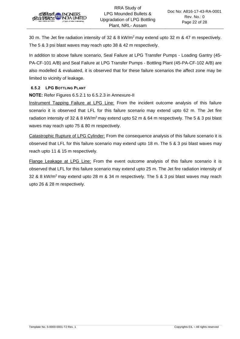
RRA Study of
LPG Mounded Bullets &
Upgradation of LPG Bottling
Plant, NRL- Assam
Doc No: A816-17-43-RA-0001
Rev. No.: 0
Page 22 of 28
Template No. 5-0000-0001-T2 Rev. 1 Copyrights EIL ¬ All rights reserved
30 m. The Jet fire radiation intensity of 32 & 8 kW/m2 may extend upto 32 m & 47 m respectively.
The 5 & 3 psi blast waves may reach upto 38 & 42 m respectively.
In addition to above failure scenario, Seal Failure at LPG Transfer Pumps - Loading Gantry (45-
PA-CF-101 A/B) and Seal Failure at LPG Transfer Pumps - Bottling Plant (45-PA-CF-102 A/B) are
also modelled & evaluated, it is observed that for these failure scenarios the affect zone may be
limited to vicinity of leakage.
6.5.2 LPG BOTTLING PLANT
NOTE: Refer Figures 6.5.2.1 to 6.5.2.3 in Annexure-II
Instrument Tapping Failure at LPG Line: From the incident outcome analysis of this failure
scenario it is observed that LFL for this failure scenario may extend upto 62 m. The Jet fire
radiation intensity of 32 & 8 kW/m2 may extend upto 52 m & 64 m respectively. The 5 & 3 psi blast
waves may reach upto 75 & 80 m respectively.
Catastrophic Rupture of LPG Cylinder: From the consequence analysis of this failure scenario it is
observed that LFL for this failure scenario may extend upto 18 m. The 5 & 3 psi blast waves may
reach upto 11 & 15 m respectively.
Flange Leakage at LPG Line: From the event outcome analysis of this failure scenario it is
observed that LFL for this failure scenario may extend upto 25 m. The Jet fire radiation intensity of
32 & 8 kW/m2 may extend upto 28 m & 34 m respectively. The 5 & 3 psi blast waves may reach
upto 26 & 28 m respectively.

RRA Study of
LPG Mounded Bullets &
Upgradation of LPG Bottling
Plant, NRL- Assam
Doc No: A816-17-43-RA-0001
Rev. No.: 0
Page 23 of 28
Template No. 5-0000-0001-T2 Rev. 1 Copyrights EIL ¬ All rights reserved
7 MAJOR FINDINGS & RECOMMENDATIONS
The detailed consequence analysis of release of hydrocarbon in case of major credible scenarios
are modeled in terms of release rate, dispersion, flammability and toxic characteristics, which
have been discussed in detail in the report. The major findings and recommendations arising out
of the Rapid Risk analysis study for facilities under Project are summarized below:
Consequence modeling of failure scenarios for LPG Mounded Bullets & associated pumping
system are modelled & studied. It is observed that in the event of realization of 20 & 10 mm
leak scenarios for LPG transfer pumps of Gantry & Bottling Plant, radiation & explosion effect
zones may be limited to leak vicinities, depending upon the prevalent weather condition &
ignition sources encountered at the time of the release and may not affect any nearby
facilities.
Adequate number of hydrocarbon detectors to be ensured at strategic locations within the
LPG pump house for early leak detection and inventory isolation and suitable sprinklers
system as per OISD requirements. It is recommended that road on northern, western &
eastern side of the LPG pump house to be classified for traffic movement.
Consequence failure modeling of leak scenarios in LPG Bottling Plant is carried out &
studied. In the event of realization of 20 & 10 mm leak scenarios in the LPG line inside
Bottling Plant, radiation & explosion effect zones may engulf & affect the whole LPG Bottling
plant, depending upon the location of the release, prevalent weather condition & ignition
sources encountered at the time of the release and may affect the personnel’s working inside
the LPG Bottling Plant.
It is recommended to ensure the hydrocarbon & fire detectors inside the Bottling Plant at
appropriate locations and suitable active/passive fire protection measures inside the Bottling
Plant. These scenarios to be also used for updation of existing Disaster Management Plan &
Emergency Response Procedures.
In the event of fire scenario inside LPG Bottling Plant, the escalation effects need to be
evaluated further, as projectiles from LPG cylinder bursting may affect & damage the other
nearby facilities / buildings in the radius of the 460 m.
a) Recommendations for Construction Safety during execution of the Project
Adequate barricading of the proposed facilities to be done from existing running facilities
during construction phase. Hydrocarbon detectors to be placed along the barricading
suitably to detect any hydrocarbon gas in vicinity of construction area.
Also, adequate firefighting & toxic gas handling arrangement are to be ensured in the
construction area. Ensure training of persons associated with construction activities for
response during fire.

RRA Study of
LPG Mounded Bullets &
Upgradation of LPG Bottling
Plant, NRL- Assam
Doc No: A816-17-43-RA-0001
Rev. No.: 0
Page 24 of 28
Template No. 5-0000-0001-T2 Rev. 1 Copyrights EIL ¬ All rights reserved
Proper material movement path within the Refinery shall be identified during the
construction phase of the project.
Detailed HSE Plan & HSE Philosophy to be developed by contractors during construction
phase of the project, in line with client’s safety requirements.
It is suggested to carry out HAZID, SIMOPS studies during pre-execution phase of the
project to get a detailed overview of the possible hazards during construction phase and
action plan to prevent / mitigate the same.
b) General Recommendations
No operator cabin shall be located in the vicinity of the LPG Mounded Bullet Pump House
and LPG Bottling Plant.
Proper checking of contract people for smoking or inflammable materials to be ensured at
entry gates to avoid presence of any unidentified source of ignition.
Ensure vehicles entering the Refinery are fitted with spark arrestors, as a mandatory item.
In order to prevent secondary incident arising from any failure scenario, it is recommended
that sprinklers and other protective devices provided on the tanks are regularly checked to
ensure these are functional.
Mock drills to be organized at organization level to ensure preparation of the personnel’s
working in Refinery for handling any hazardous situation.
For positively pressurized building, both Hydrocarbon & Toxic detectors need to be placed
at suction duct of HVAC. HVAC to be tripped automatically in event of the detection of any
Hydrocarbon / toxic material by detector.
c) Mitigating Measures
Mitigating measures are those measures in place to minimize the loss of containment event
and, hazards arising out of Loss of containment. These include:
Early detection of an undesirable event (HC leak, Toxic gas leak, Flame etc.) and
development of subsequent quick isolation mechanism for major inventories.
Active and Passive Fire Protection for critical equipment’s and major structures
Effective Emergency Response plans to be in place
d) Ignition Control
Ignition control will reduce the likelihood of fire events. This is the key for reducing the risk
within facilities processing flammable materials. As part of mitigation measure it is strongly
recommended to consider minimization of the traffic movement within the Refinery.
e) Escape Routes
Ensure sufficient escape routes from the site are available to allow redundancy in escape
from all areas.

RRA Study of
LPG Mounded Bullets &
Upgradation of LPG Bottling
Plant, NRL- Assam
Doc No: A816-17-43-RA-0001
Rev. No.: 0
Page 25 of 28
Template No. 5-0000-0001-T2 Rev. 1 Copyrights EIL ¬ All rights reserved
Ensure sufficient number of windsocks throughout the site to ensure visibility from all
locations. This will enable people to escape upwind or crosswind from flammable / toxic
releases.
Provide sign boards marking emergency/safe roads to be taken during any exigencies.
f) Preventive Maintenance for Critical Equipment’s
In order to reduce the failure frequency of critical equipment’s, the following are
recommended:
a. High head pumps and Compressors, which are in flammable / toxic services, are
needed to be identified.
i. Their seals, instruments and accessories are to be monitored closely
ii. A detailed preventive maintenance plan to be prepared and followed.
g) Others
Ensure removal of hammer blinds from the process facilities, if any.
Closed sampling system to be considered for pressurized services like LPG, Propylene
etc.
Recommended to use portable HC detector during sampling and maintenance etc.

RRA Study of
LPG Mounded Bullets &
Upgradation of LPG Bottling
Plant, NRL- Assam
Doc No: A816-17-43-RA-0001
Rev. No.: 0
Page 26 of 28
Template No. 5-0000-0001-T2 Rev. 1 Copyrights EIL ¬ All rights reserved
8 GLOSSARY
CASUALTY Someone who suffers serious injury or worse i.e. including fatal
injuries. As a rough guide fatalities are likely to be half the total
casualties. But this may vary depending on the nature of the event.
HAZARD A chemical or physical condition with the potential of causing
damage.
FLAMMABILITY LIMITS In fuel-air systems, a range of compositions exists inside which a
(UFL – LFL) flame will propagate substantial distance from an
ignition source. The limiting fuel concentrations are termed as
Upper flammability or explosives limit (Fuel concentrations
exceeding this are too rich) and Lower flammability or explosives
limit (Fuel concentrations below this are too lean).
FLASH FIRE The burning of a vapor cloud at very low flame propagation speed.
Combustion products are generated at a rate low enough for
expansion to take place easily without significant overpressure
ahead or behind the flame front. The hazard is therefore only due to
thermal effects.
OVERPRESSURE Maximum pressure above atmosphere pressure experiences during
the passage of a blast wave from an explosion expressed in this
report as pounds per square inch (psi).
EXPLOSION A rapid release of energy, which causes a pressure discontinuity or
shock wave moving away from the source. An explosion can be
produced by detonation of a high explosive or by the rapid burning
of a flammable gas cloud. The resulting overpressure is sufficient to
cause damage inside and outside the cloud as the shock wave
propagation into the atmosphere beyond the cloud. Some authors
use the term deflagration for this type of explosion
DOMINO EFFECT The effect that loss of containment of one installation leads to loss
of containment of other installations
EVENT TREE A logic diagram of success and failure combinations of events used
to identify accident sequences leading to all possible consequences
of a given initiating event.
TLV “Threshold limit value” is defined as the concentration of the
substance in air that can be breathed for five consecutive 8 hours
work day (40 hours work week) by most people without side effect.
STEL “Short Term Exposure Limit” is the maximum permissible average
exposure for the time period specified (15 minutes).

RRA Study of
LPG Mounded Bullets &
Upgradation of LPG Bottling
Plant, NRL- Assam
Doc No: A816-17-43-RA-0001
Rev. No.: 0
Page 27 of 28
Template No. 5-0000-0001-T2 Rev. 1 Copyrights EIL ¬ All rights reserved
IDLH “Immediate Dangerous to Life and Health” is the maximum
concentration level from which one could escape within 30 minutes
without any escape impairing symptoms.
PASQUILL CLASS Classification to qualify the stability of the atmosphere, indicated by
a letter ranging from A, for very unstable, to F, for stable.
FREQUENCY The number of times an outcome is expected to occur in a given
period of time.

RRA Study of
LPG Mounded Bullets &
Upgradation of LPG Bottling
Plant, NRL- Assam
Doc No: A816-17-43-RA-0001
Rev. No.: 0
Page 28 of 28
Template No. 5-0000-0001-T2 Rev. 1 Copyrights EIL ¬ All rights reserved
9 REFERENCES
1. Classification of hazardous locations, A. W. Cox, F. P. Lees and M. L. Ang, Published by
the Institute of Chemical engineers, U. K.
2. The reference manual, Volume-II, Creemer & Warner Ltd. U. K. (Presently Entec).
3. Risk analysis of six potentially hazardous industrial objects in the Rijnmond area; A pilot
study. A report to the Rijnmond Public Authority. D. Riedel publishing company, U. K.
4. Loss prevention in the process industries, Hazard identification, Assessment and Control,
Frank. P. Lees (Vol. I, II & III), Published by Butterworth-Heinemann, U. K.
5. AICHE, CCPS, Chemical process Quantitative Risk Analysis
6. Guideline for Quantitative Risk assessment, ‘Purple book’.

RRA Study of
LPG Mounded Bullets &
Upgradation of LPG Bottling
Plant, NRL- Assam
Doc No: A816-17-43-RA-0001
Rev. No.: 0
Page 1 of 2
Template No. 5-0000-0001-T2 Rev. 1 Copyrights EIL ¬ All rights reserved
ANNEXURE-I
CONSEQUENCE ANALYSIS HAZARD DISTANCES

Temp.
(OC)
Press.
(Kg/cm2g)4 KW/m2 8 KW/m2 32 KW/m2 4 KW/m2 8 KW/m2 32 KW/m2 2 psi 3 psi 5 psi
1 F 61 73 64 51 - - - 87 80 75
2 D 57 69 59 46 - - - 73 67 62
1 F 13 24 21 17 - - - 16 14 13
2 D 11 23 20 16 - - - 15 14 13
1 F 64 76 66 53 - - - 88 81 75
2 D 59 72 61 48 - - - 74 68 63
1 F 13 25 22 18 - - - 16 15 13
2 D 11 24 21 16 - - - 16 14 13
1 F 83 133 114 88 - - - 120 110 102
2 D 65 125 106 80 - - - 94 86 79
1 F 30 56 47 32 - - - 46 42 38
2 D 28 53 44 28 - - - 33 30 27
1 F 62 74 64 52 - - - 87 80 75
2 D 58 70 60 47 - - - 73 67 63
1 F 15 - - - - - - 20 15 11
2 D 18 - - - - - - 20 15 11
1 F 25 40 34 28 - - - 31 28 26
2 D 22 37 32 25 - - - 30 28 26
Mounded Bullets
18
Equipment
Bottling Plant
LPG Line Flange Leakage
0.8
Blast Over Pressure (m)
WeathersFlash Fire
(m)Failure Case
Jet Fire (m) Pool Fire (m)
16.6
Amb.
Unit
LPG Transfer Pumps - Loading Gantry
(45-PA-CF-101 A/B)Amb. 16.6
LPG Transfer Pumps - Bottling Plant
(45-PA-CF-102 A/B)
Operating Conditions
Sl No.
Instrument Tapping Failure
Catastrophic Rupture2
NOTE
1
2
3
8.2
0.7
Leak Rate
Kg/s
LPG Transfer Pumps - Loading Gantry
(45-PA-CF-101 A/B)Amb.
20.48
Amb.Saturation
pressure
5
4
1
-LPG Cylinder
Instrument Tapping Failure
Seal Failure
2.14
LPG Transfer Pumps - Bottling Plant
(45-PA-CF-102 A/B)Amb. 20.48 9.1Instrument Tapping Failure
Seal Failure
3
LPG Line Amb. 18 8.6
Amb.
Numaligarh Refinery Ltd.- LPG Mounded Bullets & LPG Bottling Plant Consequence Analysis Hazard Distances
LPG Mounded Bullet Inlet Line
(At the top of the bullet)50 mm Leak Amb. 6 30.9
6LPG Mounded Bullet Inlet Line
(At the top of the bullet)20 mm Leak Amb. 6 4.94

RRA Study of
LPG Mounded Bullets &
Upgradation of LPG Bottling
Plant, NRL- Assam
Doc No: A816-17-43-RA-0001
Rev. No.: 0
Page 1 of 27
Template No. 5-0000-0001-T2 Rev. 1 Copyrights EIL ¬ All rights reserved
ANNEXURE-II
FIGURES FOR CONSEQUENCE ANALYSIS
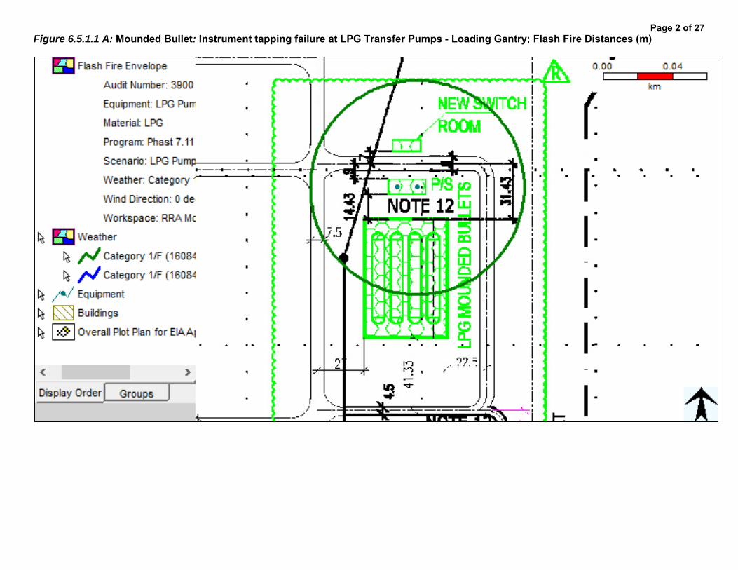
Figure 6.5.1.1 A: Mounded Bullet: Instrument tapping failure at LPG Transfer Pumps - Loading Gantry; Flash Fire Distances (m)
Page 2 of 27
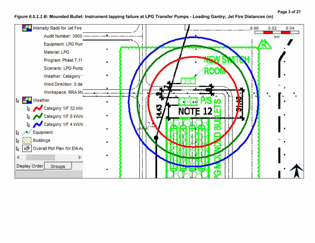
Figure 6.5.1.1 B: Mounded Bullet: Instrument tapping failure at LPG Transfer Pumps - Loading Gantry; Jet Fire Distances (m)
Page 3 of 27

Figure 6.5.1.1 C: Mounded Bullet: Instrument tapping failure at LPG Transfer Pumps - Loading Gantry; Over Pressure Distances (m)
Page 4 of 27

Figure 6.5.1.2 A: Mounded Bullet: Seal failure at LPG Transfer Pumps - Loading Gantry; Flash Fire Distances (m)
Page 5 of 27

Figure 6.5.1.2 B: Mounded Bullet: Seal failure at LPG Transfer Pumps - Loading Gantry; Jet Fire Distances (m)
Page 6 of 27

Figure 6.5.1.2 C: Mounded Bullet: Seal failure at LPG Transfer Pumps - Loading Gantry; Over Pressure Distances (m)
Page 7 of 27

Figure 6.5.1.3 A: Mounded Bullet: Instrument tapping failure at LPG Transfer Pumps – Bottling Plant; Flash Fire Distances (m)
Page 8 of 27

Figure 6.5.1.3 B: Mounded Bullet: Instrument tapping failure at LPG Transfer Pumps - Bottling Plant; Jet Fire Distances (m)
Page 9 of 27

Figure 6.5.1.3 C: Mounded Bullet: Instrument tapping failure at LPG Transfer Pumps - Bottling Plant; Over Pressure Distances (m)
Page 10 of 27

Figure 6.5.1.4 A: Mounded Bullet: Seal failure at LPG Transfer Pumps – Bottling Plant; Flash Fire Distances (m)
Page 11 of 27

Figure 6.5.1.4 B: Mounded Bullet: Seal failure at LPG Transfer Pumps - Bottling Plant; Jet Fire Distances (m)
Page 12 of 27

Figure 6.5.1.4 C: Mounded Bullet: Seal failure at LPG Transfer Pumps - Bottling Plant; Over Pressure Distances (m)
Page 13 of 27

Figure 6.5.1.5 A: Mounded Bullet: LPG Inlet line to Mounded Bullet-50 mm Hole at Top of the Mounded Bullet; Flash Fire Distances (m)
Page 14 of 27
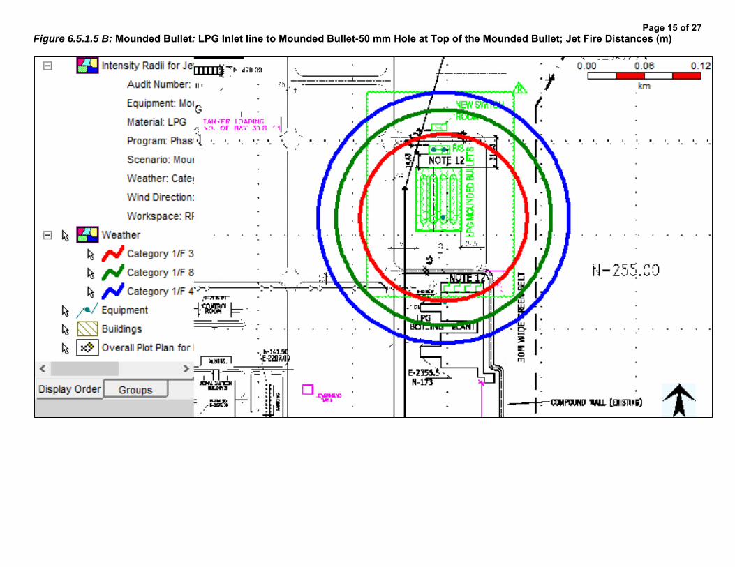
Figure 6.5.1.5 B: Mounded Bullet: LPG Inlet line to Mounded Bullet-50 mm Hole at Top of the Mounded Bullet; Jet Fire Distances (m)
Page 15 of 27

Figure 6.5.1.5 C: Mounded Bullet: LPG Inlet line to Mounded Bullet-50 mm Hole at Top of the Mounded Bullet; Over Pressure Distances (m)
Page 16 of 27

Figure 6.5.1.6 A: Mounded Bullet: LPG Inlet line to Mounded Bullet-20 mm Hole at Top of the Mounded Bullet; Flash Fire Distances (m)
Page 17 of 27

Figure 6.5.1.6 B: Mounded Bullet: LPG Inlet line to Mounded Bullet-20 mm Hole at Top of the Mounded Bullet; Jet Fire Distances (m)
Page 18 of 27

Figure 6.5.1.6 C: Mounded Bullet: LPG Inlet line to Mounded Bullet-20 mm Hole at Top of the Mounded Bullet; Over Pressure Distances (m)
Page 19 of 27

Figure 6.5.2.1 A: Bottling Plant: Instrument Tapping failure at LPG Line; Flash Fire Distances (m)
Page 20 of 27

Figure 6.5.2.1 B: Bottling Plant: Instrument Tapping failure at LPG Line; Jet Fire Distances (m)
Page 21 of 27
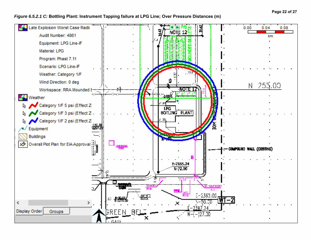
Figure 6.5.2.1 C: Bottling Plant: Instrument Tapping failure at LPG Line; Over Pressure Distances (m)
Page 22 of 27
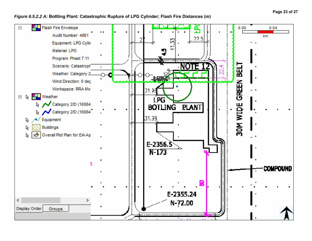
Figure 6.5.2.2 A: Bottling Plant: Catastrophic Rupture of LPG Cylinder; Flash Fire Distances (m)
Page 23 of 27

Figure 6.5.2.2 B: Bottling Plant: Catastrophic Rupture of LPG Cylinder; Over Pressure Distances (m)
Page 24 of 27

Figure 6.5.2.3 A: Bottling Plant: Flange Leakage (10mm) at LPG Line; Flash Fire Distances (m)
Page 25 of 27

Figure 6.5.2.3 B: Bottling Plant: Flange Leakage (10mm) at LPG Line; Jet Fire Distances (m)
Page 26 of 27
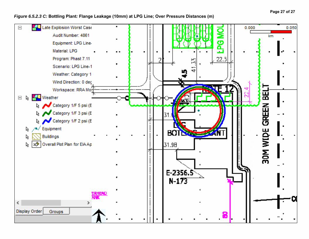
Figure 6.5.2.3 C: Bottling Plant: Flange Leakage (10mm) at LPG Line; Over Pressure Distances (m)
Page 27 of 27