risk assessment - welcome to...
TRANSCRIPT

Risk Assessment
for Expansion Project of -- Ammonia 2200 MTPD & Urea 3850 MTPD, at Village
Piprola, Distt Shahjahanpur, U.P
Submitted by:
KRIBHCO Shyam Fertilizers Limited
March 2015
Environmental Consultant:
EQMS INDIA PVT. LTD. INDIA
304-305, 3rd Floor, Plot No. 16, Rishabh Corporate Tower,
Community Centre, Karkardooma, Delhi – 110092
Phone: 011-30003200, 30003219; Fax: 011-22374775
Website: www.eqmsindia.com; Email: [email protected]
HAZARD EVALUATION AND RISK ANALYSIS
1.1. Prelude
Industrial plants deal with materials, which are generally hazardous in nature by virtue of their
intrinsic chemical properties or their operating temperatures or pressures or a combination of
these. Fire, explosion, toxic release or combinations of these are the hazards associated with
industrial plants using hazardous chemicals. More comprehensive, systematic and sophisticated
methods of Safety Engineering, such as, Hazard Analysis and Risk Assessment have now been
developed to improve upon the integrity, reliability and safety of industrial plants.
The primary emphasis in safety engineering is to reduce risk to human life, property and
environment. Some of the more important methods used to achieve this are:
Risk Analysis: Provides a relative measure of the likelihood and severity of various possible
hazardous events by critically examining the plant process and design.
Work Safety Analysis: The technique discerns whether the plant layout and operating
procedures in practice have any inherent infirmities.
Safety Audit: Takes a careful look at plant operating conditions, work practices and work
environments to detect unsafe conditions.
Together, these three broad tools attempt to minimize the chances of accidents occurring. Yet,
there always exists, no matter how remote, probability of occurrence of a major accident. If the
accident involves highly hazardous chemicals in sufficiently large quantities, the consequences
may be serious to the plant, to surrounding areas and the populations residing therein.
To meet emergencies caused by such major accidents, planning response strategies are termed
as On-site Emergency Plan /Disaster Management Plan (DMP).
DMP cannot be considered in isolation or act as a substitute for maintaining good safety
standards in a plant. The best way to protect against a major accident occurrence is by
maintaining very high levels of safety standards.
1.2. Hazards Survey
Hazard identification and risk assessment studies can be performed at any stage, that is, at
initial design stage or as on-going operation in the system. Hazard survey is a formal
systematized approach employed for hazard identification.
Appraisal of material characteristics from Material Safety Data Sheet for various materials and
chemicals used or produced in the fertilizer plant of Kribhco Shyam Fertilizer Limited (KSFL)
indicates that some of the materials are highly inflammable/explosive (Natural Gas/Naphtha) and
some are toxic (Ammonia / Chlorine etc.). In addition some of the intermediate materials

produced in the process (hydrogen and carbon monoxide) are extremely dangerous considering
the process conditions.
All process materials which are capable of producing accidents/hazards owing to their physical
and chemical properties are identified and on the basis of material movement, hold ups are
calculated. Quantities in the pipelines are also taken in to account. Large and sub-sequential
inventories in storage or process are indicative of the potential hazards to the plant and its
surroundings. Flammability and toxicity factors of these inventories can lead to the unpredictable
incidents.
KSFL is producing urea for agriculture use. The major raw materials and other consumable used
are given in Table 6.1. Most of the materials consumed (except Naphtha, Ammonia, Chlorine)
are non-hazardous in nature. However, the materials in the process i.e. NG, hydrogen, carbon
monoxide and ammonia are highly hazardous. The consequence of hazards is enhanced
considering the process conditions (high temperature and pressure). These materials need to be
handled very carefully to ensure safety.
Table 1.1 : Hazardous Materials Storages
SN Hazardous Chemicals
Handled
Quantity Handled /In
Process
Type of Storage
1 Naphtha 3 [4600;1350;600] KL MS Tanks (Main tanks 4600
KL & 1350 KL are having
floating roof while day tank -
600KL has fixed roof tank
with N2 blanketing)
2 Main Raw Material-
Natural Gas
--- Supply from GAIL through
HBJ gas line
3 Ammonia 2X 5000 MT Double walled, double
integrity Atmospheric Tanks
(0ne existing and in
proposed expansion
project).
4 Chlorine Gas 0.9X12 MT Tonnage Cylinders
5 Sulphuric Acid 2 MS Storage Tank
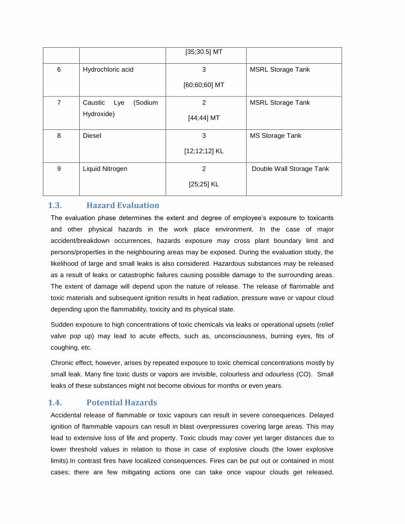
[35;30.5] MT
6 Hydrochloric acid 3
[60;60;60] MT
MSRL Storage Tank
7 Caustic Lye (Sodium
Hydroxide)
2
[44;44] MT
MSRL Storage Tank
8 Diesel 3
[12;12;12] KL
MS Storage Tank
9 Liquid Nitrogen 2
[25;25] KL
Double Wall Storage Tank
1.3. Hazard Evaluation
The evaluation phase determines the extent and degree of employee’s exposure to toxicants
and other physical hazards in the work place environment. In the case of major
accident/breakdown occurrences, hazards exposure may cross plant boundary limit and
persons/properties in the neighbouring areas may be exposed. During the evaluation study, the
likelihood of large and small leaks is also considered. Hazardous substances may be released
as a result of leaks or catastrophic failures causing possible damage to the surrounding areas.
The extent of damage will depend upon the nature of release. The release of flammable and
toxic materials and subsequent ignition results in heat radiation, pressure wave or vapour cloud
depending upon the flammability, toxicity and its physical state.
Sudden exposure to high concentrations of toxic chemicals via leaks or operational upsets (relief
valve pop up) may lead to acute effects, such as, unconsciousness, burning eyes, fits of
coughing, etc.
Chronic effect, however, arises by repeated exposure to toxic chemical concentrations mostly by
small leak. Many fine toxic dusts or vapors are invisible, colourless and odourless (CO). Small
leaks of these substances might not become obvious for months or even years.
1.4. Potential Hazards
Accidental release of flammable or toxic vapours can result in severe consequences. Delayed
ignition of flammable vapours can result in blast overpressures covering large areas. This may
lead to extensive loss of life and property. Toxic clouds may cover yet larger distances due to
lower threshold values in relation to those in case of explosive clouds (the lower explosive
limits).In contrast fires have localized consequences. Fires can be put out or contained in most
cases; there are few mitigating actions one can take once vapour clouds get released.

Therefore, major accident hazards occur upon release of flammable or toxic vapours or BLEVE
in case of pressurized flammable liquefied gases.
1.4.1. Toxic Release
In KSFL complex toxic hazards are mainly due to Ammonia (produced and stored in large
quantity) and chlorine.
Ammonia is a colourless with extremely pungent odour toxic and explosive gas (BP – 33.4C).
Ammonia is highly soluble in water (which can to an extent save an individual from its hazards).
Ammonia exposure limits are –TWA – IND 25 ppm; TWA – ACGIH 25 ppm; STEL- ACGIH 35
ppm. Ammonia is severe irritant respiratory tract. Some hazards arise due to production,
transfer, storage, handling and processing of liquefied ammonia. In case of fully refrigerated
liquid ammonia release, instantaneous flash due to adiabatic expansion is negligibly small.
Evaporation due to aerosol formation also does not occur. Release of liquid ammonia at
pressure (in ammonia plant synthesis section), gives rise to flash evaporation equivalent of the
initial flash due to adiabatic expansion. In case of HP ammonia stored at near ambient
temperature liquid released would completely vaporize with no pool formation. Ejection of high
pressure ammonia appears to entrain 10 to 15 times of its own weight of air enough to
evaporate nearly all the liquid. Thus if an HP release occurs unimpeded the ammonia entrains
sufficient air to evaporate all the droplets carried out with flash.
Chlorine is a toxic gas (B. P. is -34oC). In liquefied form chlorine is a clear amber dense liquid.
The gas is greenish-yellow, about 2.5 times as dense as air, and non-flammable. Liquid chlorine
causes severe irritation and blistering of skin. The gas has a pungent suffocating odour and is
irritant to the nose and throat. It is an extremely powerful vesicant and respiratory irritant.
Typically, exposure to chlorine concentrations of 3 - 6 ppm results in a stinging and burning
sensation in the eyes. Exposures for 0.5 -1 hour to concentrations of 14 - 21 ppm cause
pulmonary oedema, pneumonitis emphysema and bronchitis. This is usually associated with
marked bronchospasm, muscular soreness and headache. Whilst there is inevitably a variation
in individual susceptibility, typically 4 ppm is the maximum concentration that can be breathed
for one hour without any damage, 40-60 ppm is dangerous for a 30-minute exposure and a
concentration of 1000 ppm is likely to be fatal after a few breaths. IDLH (immediately Dangerous
to Life and Health) value for chlorine is 30 ppm. Permissible limit in exposure of chlorine in work
environment under Factories Act, 1948 is 1 ppm Time Weighted Average (TWA) Concentration
(8 hours).
1.4.2. Flammable Release
The flammable materials used at KSFL, involve natural gas used as feedstock, fuel gas and
synthesis gas produced in ammonia plant upstream of Synthesis converter, and naphtha. In
certain section of the plant the operating temperature itself exceeds the auto-ignition

temperature of hydrogen and carbon monoxide. In all such cases due to immediate ignition, a jet
flame will result.
1.4.3. Jet Release
Generally when a gas flows out of an opening at high velocity a turbulent free jet invariably
results. The out-flowing gas entrains a large quantity of the ambient air. The net results being the
jet getting diluted to LEL within the short distance from the release point. If ignited the jet flame
results, but if the released material does not get ignited immediately then the possibility of
vapour cloud explosion or delayed ignition is very remote because by this time free jet has lost
its momentum and the mass can begin to disperse due to environmental forces {the
concentration of flammable material has already fallen below the LEL}.
No vapour cloud explosion has therefore been considered. Jet flames due to impingement on
the adjoining important installations can lead to secondary effects (domino effect). In certain
cases the domino effects could lead/ result in loss of containment of ammonia with serious
consequences. The toxic effect of carbon -monoxide has also not been considered since any
such release due to high system operating pressure (and consequent high momentum) will
either get diluted to low concentrations within short distance from the source due to air
entrainment or will get ignited and hence the consequence distance will be rather small.
1.5. Inventory Analysis
Inventory plays an important part in regard to the potential hazard. Larger the inventory of the
vessel or a system, the larger the quantity of potential release. A practice commonly used to
generate an incident list is to consider the potential leaks and major releases from fractures of
pipelines and vessels containing sizable inventories. The potential vapour release (source
strength) depends upon the quantity of liquid release, the property of the materials and the
operating conditions (pressure). These when combined into matrix and vapour source strength
computed for each release case, a ranking should become a credible exercise. Plant inventory
can get discharged to environment due to loss of containment.
From the preliminary risk assessment study carried out for each participating unit, some of the
possible hazards have been identified. The likely accident scenarios considered are given in
Table 6.2:
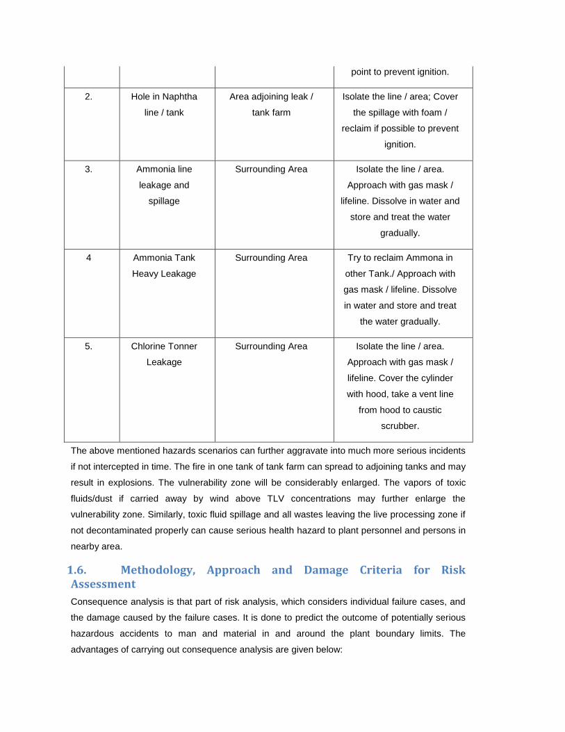
Table 1.2 : Likely Accident Scenario
S. No. Scenario Vulnerability Zone Remarks
1. Rupture in NG line Area close to leak /
release
Isolate the line / area; Cool /
drench / dilute the source
point to prevent ignition.
2. Hole in Naphtha
line / tank
Area adjoining leak /
tank farm
Isolate the line / area; Cover
the spillage with foam /
reclaim if possible to prevent
ignition.
3. Ammonia line
leakage and
spillage
Surrounding Area Isolate the line / area.
Approach with gas mask /
lifeline. Dissolve in water and
store and treat the water
gradually.
4 Ammonia Tank
Heavy Leakage
Surrounding Area Try to reclaim Ammona in
other Tank./ Approach with
gas mask / lifeline. Dissolve
in water and store and treat
the water gradually.
5. Chlorine Tonner
Leakage
Surrounding Area Isolate the line / area.
Approach with gas mask /
lifeline. Cover the cylinder
with hood, take a vent line
from hood to caustic
scrubber.
The above mentioned hazards scenarios can further aggravate into much more serious incidents
if not intercepted in time. The fire in one tank of tank farm can spread to adjoining tanks and may
result in explosions. The vulnerability zone will be considerably enlarged. The vapors of toxic
fluids/dust if carried away by wind above TLV concentrations may further enlarge the
vulnerability zone. Similarly, toxic fluid spillage and all wastes leaving the live processing zone if
not decontaminated properly can cause serious health hazard to plant personnel and persons in
nearby area.
1.6. Methodology, Approach and Damage Criteria for Risk Assessment
Consequence analysis is that part of risk analysis, which considers individual failure cases, and
the damage caused by the failure cases. It is done to predict the outcome of potentially serious
hazardous accidents to man and material in and around the plant boundary limits. The
advantages of carrying out consequence analysis are given below:
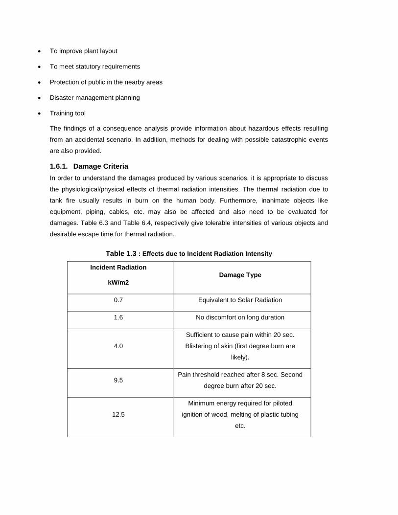
To improve plant layout
To meet statutory requirements
Protection of public in the nearby areas
Disaster management planning
Training tool
The findings of a consequence analysis provide information about hazardous effects resulting
from an accidental scenario. In addition, methods for dealing with possible catastrophic events
are also provided.
1.6.1. Damage Criteria
In order to understand the damages produced by various scenarios, it is appropriate to discuss
the physiological/physical effects of thermal radiation intensities. The thermal radiation due to
tank fire usually results in burn on the human body. Furthermore, inanimate objects like
equipment, piping, cables, etc. may also be affected and also need to be evaluated for
damages. Table 6.3 and Table 6.4, respectively give tolerable intensities of various objects and
desirable escape time for thermal radiation.
Table 1.3 : Effects due to Incident Radiation Intensity
Incident Radiation
kW/m2 Damage Type
0.7 Equivalent to Solar Radiation
1.6 No discomfort on long duration
4.0
Sufficient to cause pain within 20 sec.
Blistering of skin (first degree burn are
likely).
9.5 Pain threshold reached after 8 sec. Second
degree burn after 20 sec.
12.5
Minimum energy required for piloted
ignition of wood, melting of plastic tubing
etc.

Table 1.4 : Thermal Radiation Impact to Human
Exposure
Duration
Radiation Energy
{1% lethality;
kW/m2}
Radiation Energy
for 2nd degree
burns; kW/m2
Radiation
Energy for
1st degree
burns;
kW/m2
10 sec 21.2 16 12.5
30 9.3 7.0 4.0
1.6.2. Selected Failure Cases
Few accidental scenarios have been considered and subjected to consequence analysis /
damage zone.
1.6.2.1 Rupture in NG Line
NG consisting of 98 % methane is the main raw material (Balance higher hydro carbons and
other gases) and is used to generate hydrogen to fix atmospheric nitrogen as ammonia. Any
leakage in the pipe line {through flange joint / valve/ instrumentation fittings/ welding failure}
would result in hazardous situation. NG will be released at pressure (+ 30 kg/cm2) and also at
high temperature (depending upon the leakage point in the process).
Ambient Temperature : 350 C
Leak source size : ~ 50 mm
Burning Rate : 577 kg / min.
Incident : Flash fire

Figure 1.1 :Rupture in NG Line
Threat Zone:Threat is modelled for the thermal radiation from jet fire. The threat zones identified
are as follows:
Red : 14 meters --- (10.0 kW/(sq m) = potentially lethal within 60 sec)
Orange : 19 meters --- (5.0 kW/(sq m) = 2nd degree burns within 60 sec)
Yellow : 30 meters --- (2.0 kW/(sq m) = pain within 60 sec)
1.6.2.2 Hole in Naphtha Line/ Tank
Naphtha is used only incase NG shortage from GAIL. The two large and one small day naphtha
storage tanksand transfer lines are the likely sources of leakages. The leaked naphtha will form
a pool and incase of the naphtha catching fire, the radiation intensity / thermal load on the
adjoining area / material has been assessed as below.
Ambient Temperature : 30C Leaked Naphtha Pool Diameter : 20 m
Intensity of Radiation : 71.6 kW / m2
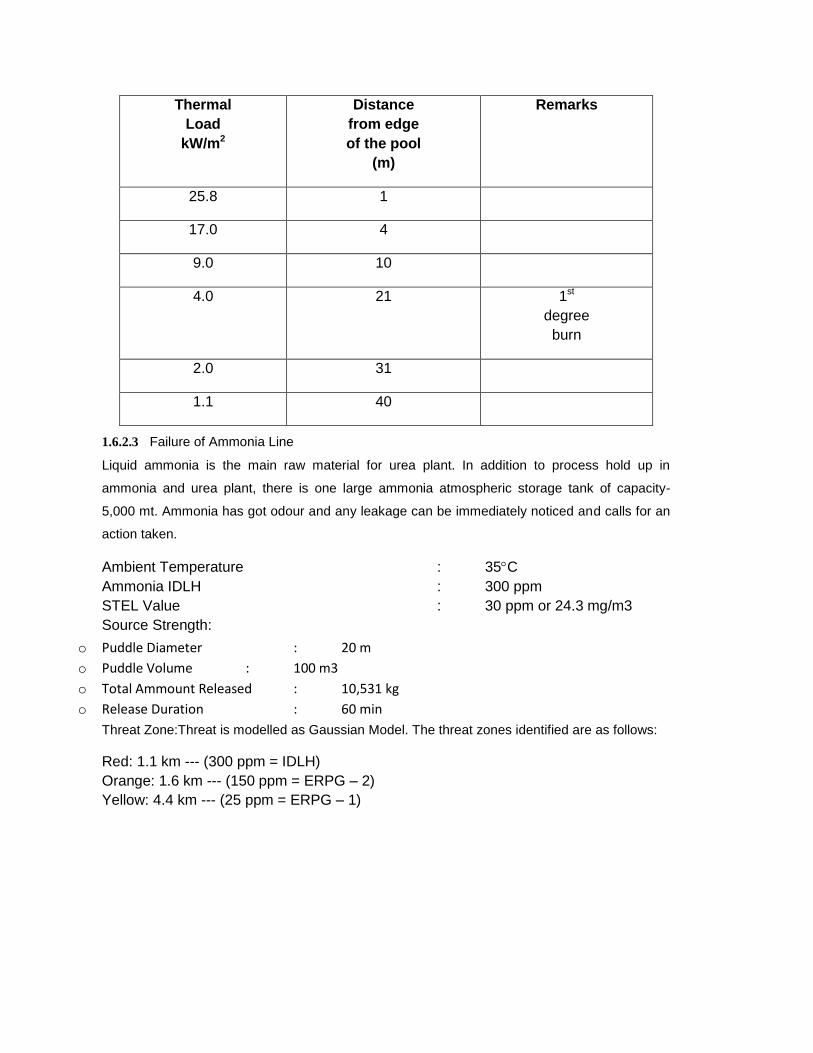
Thermal Load
kW/m2
Distance from edge of the pool
(m)
Remarks
25.8 1
17.0 4
9.0 10
4.0 21 1st degree burn
2.0 31
1.1 40
1.6.2.3 Failure of Ammonia Line
Liquid ammonia is the main raw material for urea plant. In addition to process hold up in
ammonia and urea plant, there is one large ammonia atmospheric storage tank of capacity-
5,000 mt. Ammonia has got odour and any leakage can be immediately noticed and calls for an
action taken.
Ambient Temperature : 35C Ammonia IDLH : 300 ppm STEL Value : 30 ppm or 24.3 mg/m3 Source Strength:
o Puddle Diameter : 20 m
o Puddle Volume : 100 m3
o Total Ammount Released : 10,531 kg
o Release Duration : 60 min
Threat Zone:Threat is modelled as Gaussian Model. The threat zones identified are as follows:
Red: 1.1 km --- (300 ppm = IDLH) Orange: 1.6 km --- (150 ppm = ERPG – 2) Yellow: 4.4 km --- (25 ppm = ERPG – 1)

Figure 1.2 Failure in Ammonia Line
1.6.2.4 Ammonia Tank Failure
Heavy Ammonia Leakage – Puddle Volume 4000 m3. Ammonia evaporates and spreads all
around. Try to reclaim Ammonia to other tank. Ammonia has got odour and any leakage can be
immediately noticed and calls for an action taken.
Ambient Temperature :15C Stability Class- “F” Ammonia IDLH : 300 ppm STEL Value : 30 ppm or 24.3 mg/m3 Source Strength:
o Puddle Volume : 4000 m3
Threat Zone: Threat is modelled as Gaussian Model. The threat zones identified are as follows:
Red : 1.3 kilometers --- (1100 ppm = AEGL-3 (60 min))
Orange: 3.1 kilometers --- (300 ppm = IDLH)
Yellow: 4.9 kilometers --- (160 ppm = AEGL-2 (60 min))
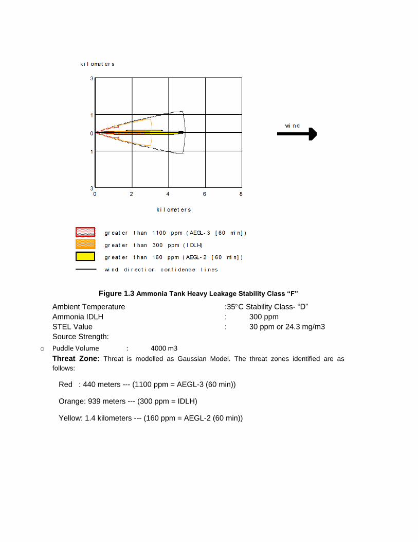
Figure 1.3 Ammonia Tank Heavy Leakage Stability Class “F”
Ambient Temperature :35C Stability Class- “D” Ammonia IDLH : 300 ppm STEL Value : 30 ppm or 24.3 mg/m3 Source Strength:
o Puddle Volume : 4000 m3
Threat Zone: Threat is modelled as Gaussian Model. The threat zones identified are as follows:
Red : 440 meters --- (1100 ppm = AEGL-3 (60 min))
Orange: 939 meters --- (300 ppm = IDLH)
Yellow: 1.4 kilometers --- (160 ppm = AEGL-2 (60 min))

Figure 1.4 Ammonia Tank Heavy Leakage Stability Class “D”
1.6.2.5 Chlorine Cylinder Leakage
Chlorine is used as biocides in cooling water system and water purification Chlorine is highly toxic (IDLH – 10 ppm). Any leakages in the system will cause toxic release which will spread in down wind direction. The dispersion due to I cm (dia) leakages are considered for modelling as below:
Ambient Temperature : 35C Chlorine IDLH Value : 10 ppm Source Strength : ~ 2 kg/ min Release Duration : 60 min
Threat Zone: Threat is modelled with heavy gas model. The threat zones identified are as follows:
Red : 157 m --- (20 ppm = AEGL*-3 (60 min)1 Orange : 226 m --- (10 ppm = IDLH) Yellow : 526 m --- (2 ppm = AEGL-2 (60 min))
1AEGL – Acute Exposure Guideline Level

Figure 1.5 Chlorine Cylinder Leakage
1.7. General Control Measures
Since some of the substances in use at KSFL are hazardous with severe fire and explosion potential and also toxic in nature, it is necessary to use appropriate control measures recommended for such substances:
1.7.1. Flammable Gas Fires
Fire control generally consists of directing, diluting and dispersing the inflammable gas/vapor to prevent contact with persons, to prevent it from infiltrating structures if the leak is out door, and to avoid its contact with ignition sources while, if possible, simultaneously stopping the flow of gas. NG is lighter than air it will go up in the atmosphere once its momentum due to pressure gets dissipated. Gas direction, dilution and dispersion require the use of a carrier fluid, and air, water and steam have proven to be practical carriers. Water in the form of spray, applied from hoses or monitor nozzles or by fixed water spray system may act as a good carrier fluid for inflammable vapors/gases.
1.7.2. Protection against BLEVE
A basic BLEVE safeguard is to reduce the chance of the thermal (fire) exposure to the container. During a fire exposure the application of water is a basic safeguard to prevent a BLEVE or a compressed gas container failure. Automatic sprinkler protection can greatly limit pressure rise from heat and high metal temperatures from fire exposures.
All pressure vessels and tanks should be periodically inspected for leakage from vessels and its appurtenances. Gas detection instruments/ acoustic gas leak detectors are invaluable help in detecting the leakages.
Over pressure protection devices, namely, relief valves, rupture discs, alarms, etc. are to be regularly checked and calibrated if required.
1.7.3. Commonly Recommended Control Measures
A number of preventive control measures for hazardous occurrences have been analyzed and discussed above. Some more salient points are enumerated below:
All storage tanks in the tank farm should be dyked and those storing volatile material may be provided with non-combustible insulation within aluminums protection jacket. The tanks should have water deluge system.
Ammonia has got odour. Always look for wind direction while moving in ammonia prone area. Move / approach across or up wind direction. Ammonia is highly soluble in water. A wet handkerchief / cloth are helpful in such a case. While planning a job in such area keep breathing apparatus / gas mask/ water hose ready for emergency.
Concentration detectors for hazardous chemical vapors fire Smoke / heat detectors and fire alarm should be installed at all strategic locations in the plant.
A schedule for preventive maintenance including health survey of all plant equipment should be adhered to as far as possible.
Ensure the absence of ignition sources in Naphtha / HSD / Ammonia storage area. Ensure placement of fire fighting facilities, such as, carbon dioxide, dry chemical powder and
foam type fire extinguishers in addition to fire hydrant system, at strategic locations. Spill control measures, such as, removal of all ignition sources from the spill area and ventilating the area as well as soaking the spilled material with paper, towel or mud and letting the volatile substance evaporate slowly in a safe area.
Compulsory use of protective clothing, non-sparking tools and warning signs during critical operations and maintenance.
Training / refresher courses on safety information’s / norms. Eyewash and showers should be put up at strategic places for use during emergencies.
A group of plant personnel should be trained in first aid, rescue, fire fighting and emergency control measures. These personnel will form core group/emergency squad who will fight the emergency and also act as rescue and first aid team.
In order to ensure communication from isolated places/locations Walkie-Talkie be made available to persons working in these areas. This will considerably improve the effectiveness of emergency management.
There is no substitute for training-mock drills and these must be held at regular interval keeping the following objectives in mind:
Real time mock-drill should be carried out for probable/likely hazardous situation. Target to be set up for various tasks and events during an emergency.

Weak links should be marked and corrective action taken to improve effectiveness during emergency.
KSFL has already implemented many of the measures.