rock material recycling in tunnel engineering
TRANSCRIPT
applied sciences
Article
Rock Material Recycling in Tunnel Engineering
Klaus Voit * and Erik KuschelInstitute of Applied Geology, University of Natural Resources and Life Sciences, Vienna, Peter Jordan-Street 82,1190 Vienna, Austria; [email protected]* Correspondence: [email protected]
Received: 17 March 2020; Accepted: 9 April 2020; Published: 15 April 2020�����������������
Abstract: In the construction industry, especially in tunneling or large-scale earthworks projects, hugequantities of excavation material are generated as a by-product. Although at first glance such materialis undesirable, in many cases this material, if suitably treated and processed, can be recycled andreused on the construction site and does not necessarily need to be removed and deposited as wasteat a landfill. In the simplest case, the material can be used as filling material with the least demandingrequirements with regard to rock quality. Material of better quality often can be recycled as aggregateand be used as a substitute for conventional mineral aggregates. This approach generates numerousbenefits regarding the costs for material procurement, storage and transport. In addition, reductionin environmental impact and demand for landfill volume can be achieved. The challenge lies in thefact that excavation material is not a standard aggregate in terms of geometric, physical and chemicalcharacteristics and is subject to quality deviations during tunnel driving, mainly depending on thevarying geology and applied excavation method. Therefore, preliminary research and experimentaltesting as well as specific evaluation and continuous examination of the rock quality during tunneldriving is necessary as well as ongoing adjustment of the rock processing plant to finally accomplisha high-quality level of recycled aggregates. This article illustrates the material investigations andtreatment processes for the specific example of the Brenner Base Tunnel, the longest undergroundrailway line in the world that is currently under construction. There, material recycling has alreadybeen successfully implemented.
Keywords: excavation material recycling; tunnel spoil; calcareous schists; aggregate for concrete
1. Introduction
In Europe, the mountain chains of the Alps stretch from the Gulf of Genoa to the lowland plains ofHungary, separating the main economic regions within the European Union. This is why tunnels andespecially railway tunnels of significant length are essential to ensure the functional capability of theoverall network. Numerous tunnels have been built in the past and are currently under constructionor in the planning process. In this process, large quantities of excavation material from the bedrockare generated as an unwanted by-product or “waste”, whereby handling and treatment of tunnelexcavation material is a fundamental subject in a tunnel construction project, often deciding on theeconomic and environmental success of the construction project itself [1,2].
The aim of this article is to demonstrate the recycling process of tunnel excavation material assubstitute for conventional aggregate by the example of the Brenner Base Tunnel in Austria, illustratingthe scientific approach, experimental setup as well as the practical implementation accompanied byexperimental verification due to its challenging geological bedrock conditions.
The strategy of an extensive material recycling has already been successfully implemented in theconstruction of some of the world longest tunnels: the Swiss base tunnels Lötschberg and GotthardBase Tunnel [3,4]. There, a self-supply of the construction sites with recycled aggregate that was mostlyproduced in situ on site was implemented [4–6].
Appl. Sci. 2020, 10, 2722; doi:10.3390/app10082722 www.mdpi.com/journal/applsci

Appl. Sci. 2020, 10, 2722 2 of 16
Apart from this, numerous other recently completed and currently ongoing research projectsdeal within this research question. For example, [7,8] gave an overview about the main aspects oftunnel muck recycling and its properties and application opportunities. Ref. [9,10] demonstrated theimpact of different excavation methods, particularly examining the impact of excavation by a tunnelboring machine in contrast to blasting. Ref. [11] showed the recycling of tunnel excavation material inearthworks following the premise of maximum resource saving. In other research projects, it could beshown that, if complying certain conditions, the use of excavation material as aggregate resource forthe construction of roads [12,13], power plants and concrete dam constructions [14] is feasible. Ref. [15]again concentrated on rock classification and the reuse possibilities of rocks from weak formations.
Moreover, the scientific approach concerning the usage of excavation material reaches fromplanning and decision processes by handling of excavation material [2] to the technologicalimplementation [16], focusing on the technical developments in relation to material analysis andthe realization of a raw material database to manage materials analysis, and also addresses legalconsiderations regarding the use of the recycled “waste” [17–19]. Therefore, large international researchprojects (i.e., [20]) have been conducted in the framework of sustainable raw material productionand recycling. Not least, structural engineering considerations regarding tunnel design need to beperformed when using recycled aggregate for construction concrete to fulfill the projected servicelifetime of the tunnel structure [21,22] as well as consideration in regards to the functioning ofsubsequent fastening systems in concrete using recycled aggregate [23].
In conclusion—particularly in view of saving resources and environmental protection—the aimmust be a maximum material recycling proportion of the a priori “waste“, not depositing it as landfillmaterial, and considering geological, technical and legal aspects, making it a very interdisciplinaryarea of research. As a result of this, there are also significant efforts to achieve an equally high levelof recycling of tunnel excavation material during the currently ongoing construction of the BrennerBase Tunnel. There, excavated calcareous schists have already been processed and recycled duringconventional tunnel driving of an access tunnel from 2014 to 2017, demonstrating the technological andlogistical feasibility [24,25]. At the current construction section from Pfons to Brenner, that started inautumn 2018, the recycling of the excavated rock plays an important role in providing rock aggregatefor the construction site. There, the reuse of rock material mostly excavated during continuous tunneldriving at a variable geology is a demanding task with a particular importance regarding qualitymanagement due to its use for high-grade concrete products such as lining or structural concrete.
2. Recycling Prediction at the Brenner Base Tunnel
In the course of its driving work, a total of ca. 43 M tons of excavation material are predicted forthe Brenner Base Tunnel, from which ca. 25 M tons are attributed to the Austrian tunnel section.
Whether the excavated material from the Brenner Base Tunnel is suitable for its particularapplication is mainly decided by the type and quality of the excavated rock or soil. Forecastsconcerning the possible recycling extent during the preceding environmental impact assessment in2008 stated a recovery rate of only about 6% of the excavated rock to be used as aggregates for concreteand ca. 15% as filling materials [26,27]. However, this would mean that the remaining ca. 79% ofthe excavated material needs to be deposited, at least without any further treatment of the excavatedrock material. The aim should be to reach the maximum possible recycling quota by optimizing theprocessing method and material management concept [28].
In view of these framework conditions, a landfill concept was established using possibledepositional areas and shortest possible distances from tunnel portals and, more importantly, theaccess tunnels (Figure 1).

Appl. Sci. 2020, 10, 2722 3 of 16
Appl. Sci. 2019, 9, x FOR PEER REVIEW 3 of 18
Figure 1. Planned landfill sites along the route of the Brenner Base Tunnel, cubatures in million cubic metres according to [28].
The main landfill area in the Padastertal Valley is thereby located centrally at the access tunnel Wolf. From a lithologic point of view, the Padastertal Valley deposit lies in the middle of the Bündner Schists, while the Ahrental deposit covers the excavation material mainly from the Innsbruck Quartz Phyllite unit as well as from the northernmost part of the Bündner Schist unit. At the Ahrental landfill, excavation material from the Bündner Schist unit was also deposited (Figure 2) from the exploratory tunnel by a tunnel driving machine with a diameter of approximately 5 m.
(a) (b)
Figure 2. (a) View from the Ahrental landfill with tunnel boring machine material from Bündner Schist rocks; (b) Detailed view of the excavation material from Figure 2a (fines washed out by rain at the surface).
3. Geological Overview of the Brenner Base tunnel
The Brenner Base Tunnel, with a total length of 64 km, including the bypass of Innsbruck, is the centrepiece of the Scandinavia–Mediterranean Corridor, cutting through the Brenner massif between Innsbruck (Austria) and Franzensfeste in Southern Tyrol (Italy). The tunnel passes just east of the Wipptal Valley and runs approximately parallel to it. From a geological viewpoint, the Wipptal
Figure 1. Planned landfill sites along the route of the Brenner Base Tunnel, cubatures in million cubicmetres according to [28].
The main landfill area in the Padastertal Valley is thereby located centrally at the access tunnelWolf. From a lithologic point of view, the Padastertal Valley deposit lies in the middle of the BündnerSchists, while the Ahrental deposit covers the excavation material mainly from the Innsbruck QuartzPhyllite unit as well as from the northernmost part of the Bündner Schist unit. At the Ahrental landfill,excavation material from the Bündner Schist unit was also deposited (Figure 2) from the exploratorytunnel by a tunnel driving machine with a diameter of approximately 5 m.
Appl. Sci. 2019, 9, x FOR PEER REVIEW 3 of 18
Figure 1. Planned landfill sites along the route of the Brenner Base Tunnel, cubatures in million cubic metres according to [28].
The main landfill area in the Padastertal Valley is thereby located centrally at the access tunnel Wolf. From a lithologic point of view, the Padastertal Valley deposit lies in the middle of the Bündner Schists, while the Ahrental deposit covers the excavation material mainly from the Innsbruck Quartz Phyllite unit as well as from the northernmost part of the Bündner Schist unit. At the Ahrental landfill, excavation material from the Bündner Schist unit was also deposited (Figure 2) from the exploratory tunnel by a tunnel driving machine with a diameter of approximately 5 m.
(a) (b)
Figure 2. (a) View from the Ahrental landfill with tunnel boring machine material from Bündner Schist rocks; (b) Detailed view of the excavation material from Figure 2a (fines washed out by rain at the surface).
3. Geological Overview of the Brenner Base tunnel
The Brenner Base Tunnel, with a total length of 64 km, including the bypass of Innsbruck, is the centrepiece of the Scandinavia–Mediterranean Corridor, cutting through the Brenner massif between Innsbruck (Austria) and Franzensfeste in Southern Tyrol (Italy). The tunnel passes just east of the Wipptal Valley and runs approximately parallel to it. From a geological viewpoint, the Wipptal
Figure 2. (a) View from the Ahrental landfill with tunnel boring machine material from Bündner Schistrocks; (b) Detailed view of the excavation material from Figure 2a (fines washed out by rain at thesurface).
3. Geological Overview of the Brenner Base Tunnel
The Brenner Base Tunnel, with a total length of 64 km, including the bypass of Innsbruck, is thecentrepiece of the Scandinavia–Mediterranean Corridor, cutting through the Brenner massif between

Appl. Sci. 2020, 10, 2722 4 of 16
Innsbruck (Austria) and Franzensfeste in Southern Tyrol (Italy). The tunnel passes just east of theWipptal Valley and runs approximately parallel to it. From a geological viewpoint, the Wipptal Valleyis delimited by the Tauern Window (Penninic) in the east and the Eastern Alpine Kristallin to itswest. North of the Brenner mountain massif, the Northern Limestone Alps are located. To its south,segregated by the Periadriatic Fault, the Southern Alpine with the Brixner Granite and, further to thesouth, the Southern Calcareous Alps are situated [28,29].
The rock types that are excavated belong—with the exception of the Brixener Granite—tometamorphic rocks. From a quantitative point of view, the major part of the tunnel runs through theBündner Schists, followed by the Innsbrucker Quartz Phyllites, Central Gneisses and the BrixenerGranite, whereby the Austrian tunnel section is almost entirely located within the first two, as shownin Figure 3 [29].
Appl. Sci. 2019, 9, x FOR PEER REVIEW 4 of 18
Valley is delimited by the Tauern Window (Penninic) in the east and the Eastern Alpine Kristallin to its west. North of the Brenner mountain massif, the Northern Limestone Alps are located. To its south, segregated by the Periadriatic Fault, the Southern Alpine with the Brixner Granite and, further to the south, the Southern Calcareous Alps are situated [28,29].
The rock types that are excavated belong—with the exception of the Brixener Granite—to metamorphic rocks. From a quantitative point of view, the major part of the tunnel runs through the Bündner Schists, followed by the Innsbrucker Quartz Phyllites, Central Gneisses and the Brixener Granite, whereby the Austrian tunnel section is almost entirely located within the first two, as shown in Figure 3 [29].
Figure 3. Simplified geological cross section through the Brenner Base tunnel according to [29].
The rocks of the Central Gneiss and the Brixener Granite show high rock strength with more than 100 and 130 N/mm², respectively, and solid rock properties suitable for a wide use with regard to recycling. In contrast to that, Bündner Schists and Quartz Phyllites are metamorphic rocks, showing a significant schistosity due to quite large amounts of sheet silicates and a rather low to moderate rock strength is present [30].
4. Rock Characteristics of Quartz Phyllites and Bündner Schists
4.1. Rock Quality of the Source Rocks
In general, if recycling of the excavated material is considered, the prospects depend mainly on two factors. Fundamentally, the (1) type of source rock determines the quality of the excavated rock aggregate. While in the planning phase of a tunnel, the local geological subsoil is investigated in detail, the tunnel route is determined in accordance with other criteria than the recyclability of the source rock: next to technical framework conditions, like tunnel gradient, building logistics and conservation concept, legal issues and political decisions are of primary importance [16,17,19]. Thus, the existing rock material is applied to an optimum utilization at the given conditions by adapting the sorting and processing to the local conditions. Furthermore, the (2) method of tunnel excavation—drill and blast or tunnel boring machine driving—affects the geometric properties and therefore significantly influences the extent of recycling, see chapter 4.2.
In the case of the Brenner Base tunnel, the a priori uncertain rock units of the Innsbruck Quartz Phyllites and Bündner Schists were evaluated regarding its recycling potential. Quartz Phyllites and Bündner Schists are metamorphic rocks showing a significant schistosity due to quite large amounts of sheet silicates as well as rather low to moderate rock strength. Due to this, rock material from the Bündner Schist and Quartz Phyllite was tested including large scale processing experiments. A wide range of rock examinations concerning the geometric, physical and chemical properties as well as intensive concrete production and testing were herein performed. The feasibility study finally showed the suitability for recycling of calcareous rocks of the Bündner schist unit [30,31].
As a first step, excavation material derived by drill and blast tunneling of the Innsbruck Quartz Phyllite as well as the calcareous Bündner Schists—the latter were obviously most suitable for
Figure 3. Simplified geological cross section through the Brenner Base tunnel according to [29].
The rocks of the Central Gneiss and the Brixener Granite show high rock strength with more than100 and 130 N/mm2, respectively, and solid rock properties suitable for a wide use with regard torecycling. In contrast to that, Bündner Schists and Quartz Phyllites are metamorphic rocks, showing asignificant schistosity due to quite large amounts of sheet silicates and a rather low to moderate rockstrength is present [30].
4. Rock Characteristics of Quartz Phyllites and Bündner Schists
4.1. Rock Quality of the Source Rocks
In general, if recycling of the excavated material is considered, the prospects depend mainly ontwo factors. Fundamentally, the (1) type of source rock determines the quality of the excavated rockaggregate. While in the planning phase of a tunnel, the local geological subsoil is investigated in detail,the tunnel route is determined in accordance with other criteria than the recyclability of the sourcerock: next to technical framework conditions, like tunnel gradient, building logistics and conservationconcept, legal issues and political decisions are of primary importance [16,17,19]. Thus, the existingrock material is applied to an optimum utilization at the given conditions by adapting the sorting andprocessing to the local conditions. Furthermore, the (2) method of tunnel excavation—drill and blast ortunnel boring machine driving—affects the geometric properties and therefore significantly influencesthe extent of recycling, see Section 4.2.
In the case of the Brenner Base tunnel, the a priori uncertain rock units of the Innsbruck QuartzPhyllites and Bündner Schists were evaluated regarding its recycling potential. Quartz Phyllites andBündner Schists are metamorphic rocks showing a significant schistosity due to quite large amountsof sheet silicates as well as rather low to moderate rock strength. Due to this, rock material from theBündner Schist and Quartz Phyllite was tested including large scale processing experiments. A widerange of rock examinations concerning the geometric, physical and chemical properties as well as

Appl. Sci. 2020, 10, 2722 5 of 16
intensive concrete production and testing were herein performed. The feasibility study finally showedthe suitability for recycling of calcareous rocks of the Bündner schist unit [30,31].
As a first step, excavation material derived by drill and blast tunneling of the Innsbruck QuartzPhyllite as well as the calcareous Bündner Schists—the latter were obviously most suitable for processingand recycling—was tested. Physical, chemical and geometric rock parameters were obtained withregard to is suitability as aggregate for concrete (Table 1) [25,31].
Table 1. Main physical and chemical rock properties of Quartz Phyllites and Bündner Schists [25].
Rock Properties Quartz PhylliteArithm. Mean *
Bündner SchistArithm. Mean * Evaluation
Bulk density [g/cm3] 2.7 2.7 required > 2.3Water absorption [%] 0.4 1.7 low and rather highUnconfined compressive strength[N/mm2] 45.0 76.0 required > 50 MPa
Los Angeles value 25.9 31.7 LA30, LA35E-Modulus [GPa] 24.8 38.2 -Tensile strength [N/mm2] 4.8 8.5 -Point load index Is [N/mm2] 4.0 5.8 -Schmidt hammer [N/mm2] 45.0 52.6 -Freeze/thaw resistance [%](EN 1367-1) 0.4 0.5 F1
CAI Cerchar 4.2 1.3 very abrasive andabrasive
LCPC LAK [g/t] 326.6 593.3 abrasive and veryabrasive
LCPC LBR (%) 54.9 52.3 highly crushableEquiv. quartz amount [%] 56.8 43.8 -Amount of mica and chlorite [%] 28.0 29.8 -Acid-soluble sulfate [%] - 0.58 required < 0.8%Water-soluble chloride [%] - 0.0042 required < 0.01%
* at least three individual measurements.
As shown in Table 1, water absorption, as an indication of rock porosity and aggregate frostresistance, is low in the case of the Quartz Phyllite rock material. This means that only very little wateris absorbed by this rock type, unlike the Bündner Schist rocks, which show rather high absorptionvalues on first examination, but finally, without having a negative impact on freeze/thaw resistance,attain top class F1 in both cases (according to European standard EN 12620 ‘aggregate for concrete’).
The compression test results for the Quartz Phyllite rock type, as well as point load testing andSchmidt hammer test as indirect compressive strength test methods, show rather low rock strength,only marginally acceptable for many applications. In the case of the Bündner schists, rock strength ismediocre, but still satisfactory. Both rock types, especially the Quartz Phyllites, show a rather lowE-modulus compared to standard aggregate meaning that concrete made of these aggregates will alsohave rather low E-modulus values. Concerning elastic deformation of, e.g., concrete linings, this is anadvantage because of reduced crack development, though also suffering higher deformation rates,see [22].
Resistance against impact and abrasive loads, expressed by the Los Angeles (LA) value (accordingto the European standard EN 1097-2), in both cases is mediocre, possibly causing increased loss ofmaterial as fines during material processing because of increased crushing. In addition, both rocktypes indicated abrasive to very abrasive rock characteristics expressed via Cerchar (see Europeanstandard EN 14157 regarding the determination of abrasion resistance) and LCPC values (developedby the ‘Laboratoire central des ponts et chaussées’, France, tested according to French standardAFNOR P18-579) and via the equivalent quartz amount (evaluated via rock thin section examination

Appl. Sci. 2020, 10, 2722 6 of 16
under the microscope), causing increased processing machine ware and maintenance costs duringaggregate production.
The amount of mica and chlorite is typically high as expected for Phyllite and Schist rock types,complicating the processing and adversely affecting the geometric properties of the produced aggregate.Mainly because of this fact, the very first outlook for rock recycling in [26,27] was rather negative, asmentioned in Section 2.
The Bündner Schist rock was additionally tested regarding the suitability as aggregate for concrete,investigating the acid-soluble sulfate and water-soluble chloride according to European standard ‘Testsfor chemical properties of aggregates—Part 1: Chemical analysis’ EN 1744-1. The latter showed goodresults, lying below the normatively required limit value, while the amount of acid-soluble sulfate istoo high, making concrete mix adjustments necessary, above all imposing cement types with low alkalicontent and the use of additives like fly ash or slag sand [25].
All physical properties considered, the properties of calcareous Bündner Schist rocks generallyallow the reuse of crushed rock aggregate for the production of concrete at medium to high abrasion ofthe processing plant and a special focus on its geometric properties especially its grain size distributionas well as schistosity and layered rock texture. Normative requirements should be feasible by reasonableeffort in material processing through proper crushing, screening and washing [25,30].
4.2. Tunnel Driving Method and Its Impact on Rock Material Quality
Next to the physical properties of the rock material itself, the excavation method has a major effecton grain size distribution, percentage of fines and shape of the aggregate which are the decisive factorswith regard to usability.
4.2.1. Excavation by Blasting
During drilling and blasting, tunnel driving is carried out in individual working steps that can beassigned to three main work processes [32]:
1. Breaking of rock: drilling, loading with dynamite, blasting and ventilation2. Mucking: material transport via dump trucks, on rails or by conveyor belts3. Support: rock-face sealing with shotcrete, using anchors, tunnel arches, etc.
Rock fragments generated by drill and blast are generally significantly larger than using a tunnelboring machine. The character of the excavation material is given by the progress of explosion itself: inhomogenous material, the explosion effect is spherical and decreases with increasing distance fromthe explosive charge. As rock is usually inhomogeneous, joint faces as well as fractures influence theprogress of the explosion; research and modelling on this topic is, inter alia, shown in [33–35]. Withinthe closest proximity, the rock is completely crushed through the developing gas pressure. This isfollowed by a slinging area, where rock is ejected from the bedrock formation with the emergenceof radial cracks. At even greater distances, the rock is no longer crushed actively, but is subjectedto strong vibrations and cracks. Finally, rock size is determined by the quantity of explosives—intunneling, the amount of explosive material is much greater than in quarrying sites, thus receivingsmaller sized aggregates [36].
4.2.2. Excavation via Tunnel Boring Machine (TBM)
By continuous tunnel driving via TBM, the removal process is done in one process throughoutthe entire cross section. The cutting discs at the drilling head are pushed at high pressure against thetunnel face (Figure 4). In the course of the discs’ rolling movement, rock is excavated in the form ofchips. Thereby, the penetration throughout one rotation is ca. 10 to 15 mm. The cuttings are conveyedby scrapers and removed by a conveyor belt.

Appl. Sci. 2020, 10, 2722 7 of 16
Common cutting discs show a diameter of ca. 17 to 19 inches, and the contact pressure is about200 to 300 kN, causing tensile stress in the rock [36]. The tensile strength is exceeded, radial cracks aredeveloped and the rock bursts chip-shaped (Figure 4).
Appl. Sci. 2019, 9, x FOR PEER REVIEW 8 of 18
chips. Thereby, the penetration throughout one rotation is ca. 10 to 15 mm. The cuttings are conveyed by scrapers and removed by a conveyor belt.
Common cutting discs show a diameter of ca. 17 to 19 inches, and the contact pressure is about 200 to 300 kN, causing tensile stress in the rock [36]. The tensile strength is exceeded, radial cracks are developed and the rock bursts chip-shaped (Figure 4).
Figure 4. Chip-shaped rock removal by cutting discs according to [32].
The quality of the excavated rock is – from a mechanical perspective – mainly influenced by the contact pressure. If the pressure increase is too high, intensified crack development is the consequence and the cuttings show damage by cracks. Also, rock fragmentation has a major influence on excavated aggregate characteristics [37,38]. The presence of schistosity or foliation favors the occurrence of stem-like or platy aggregate shapes [30].
4.3. Geometric Characteristics of the Excavated Rock Material
In the case of the Bündner Schists at the Brenner Base Tunnel, the grain size distribution after excavation can be characterized as follows (Figure 5): fine particles smaller that 0.063 mm in the case of blasting amount to ca. 4.4%, and in the case of continuous driving to ca. 9.4%. In the latter case, the pathway of the particle size distribution shows a steep curve shape between 4 and 30 mm, while through blasting a generally more continuous curve shape is achieved. For comparison purposes, the particle size distribution of Quartz Phyllites from drilling and blasting is also shown in Figure 5.
Figure 5. Grain-size distribution from tunnel excavation material (Quartz phyllite from blasting ca. tunnel km 7; Bündner Schists from blasting ca. km 22; Bündner Schists from tunnel boring machine ca. km 15; see Figure 3).
Figure 4. Chip-shaped rock removal by cutting discs according to [32].
The quality of the excavated rock is— from a mechanical perspective—mainly influenced by thecontact pressure. If the pressure increase is too high, intensified crack development is the consequenceand the cuttings show damage by cracks. Also, rock fragmentation has a major influence on excavatedaggregate characteristics [37,38]. The presence of schistosity or foliation favors the occurrence ofstem-like or platy aggregate shapes [30].
4.3. Geometric Characteristics of the Excavated Rock Material
In the case of the Bündner Schists at the Brenner Base Tunnel, the grain size distribution afterexcavation can be characterized as follows (Figure 5): fine particles smaller that 0.063 mm in the caseof blasting amount to ca. 4.4%, and in the case of continuous driving to ca. 9.4%. In the latter case,the pathway of the particle size distribution shows a steep curve shape between 4 and 30 mm, whilethrough blasting a generally more continuous curve shape is achieved. For comparison purposes, theparticle size distribution of Quartz Phyllites from drilling and blasting is also shown in Figure 5.
Appl. Sci. 2019, 9, x FOR PEER REVIEW 8 of 18
chips. Thereby, the penetration throughout one rotation is ca. 10 to 15 mm. The cuttings are conveyed by scrapers and removed by a conveyor belt.
Common cutting discs show a diameter of ca. 17 to 19 inches, and the contact pressure is about 200 to 300 kN, causing tensile stress in the rock [36]. The tensile strength is exceeded, radial cracks are developed and the rock bursts chip-shaped (Figure 4).
Figure 4. Chip-shaped rock removal by cutting discs according to [32].
The quality of the excavated rock is – from a mechanical perspective – mainly influenced by the contact pressure. If the pressure increase is too high, intensified crack development is the consequence and the cuttings show damage by cracks. Also, rock fragmentation has a major influence on excavated aggregate characteristics [37,38]. The presence of schistosity or foliation favors the occurrence of stem-like or platy aggregate shapes [30].
4.3. Geometric Characteristics of the Excavated Rock Material
In the case of the Bündner Schists at the Brenner Base Tunnel, the grain size distribution after excavation can be characterized as follows (Figure 5): fine particles smaller that 0.063 mm in the case of blasting amount to ca. 4.4%, and in the case of continuous driving to ca. 9.4%. In the latter case, the pathway of the particle size distribution shows a steep curve shape between 4 and 30 mm, while through blasting a generally more continuous curve shape is achieved. For comparison purposes, the particle size distribution of Quartz Phyllites from drilling and blasting is also shown in Figure 5.
Figure 5. Grain-size distribution from tunnel excavation material (Quartz phyllite from blasting ca. tunnel km 7; Bündner Schists from blasting ca. km 22; Bündner Schists from tunnel boring machine ca. km 15; see Figure 3).
Figure 5. Grain-size distribution from tunnel excavation material (Quartz phyllite from blasting ca.tunnel km 7; Bündner Schists from blasting ca. km 22; Bündner Schists from tunnel boring machine ca.km 15; see Figure 3).
Looking at the aggregate shape, the following picture emerges (Table 2): the a priori existingschistosity of the calcareous schist causes very high shape index values (the shape index SI is definedas the percentage of aggregate weight, at which length to width ratio is ≥3, determined via caliperaccording to European standard EN 933-4) in both cases, by blasting as well as continuous tunnel

Appl. Sci. 2020, 10, 2722 8 of 16
driving. On closer observation, the grain shape is even more cubic in the case of continuous driving.This may be explained by the fact that the driving direction of the TBM is perpendicular to the dipdirection of the schistosity that slightly counteracts the plate-shaped grain shape.
Table 2. Grain shape characterization via shape index (percentage of aggregate weight, at which lengthto width ratio is ≥3) depending on aggregate size and driving method.
AggregateCharacterization Blasting Tunnel Boring Machine
Particle size group (mm) 4/8 8/16 16/32 4/8 8/16 16/32Shape Index [%] 68 81 84 66 73 74
Figure 6 shows an example of typical grain shapes for Bündner Schist aggregate (non-processed)for the particle size group 8/16 and 16/32 mm from tunnel boring machine driving, resulting in anoverall shape index SI of 73 and 74 (see Table 2), respectively. The elongated and plate-like grain shapesindicate a high grade of flakiness (see also Section 5.3). The geometric character of the non-processedaggregate therefore is not suitable in regard to the handling, processing and installing of the aggregateand needs to be improved during raw material processing.Appl. Sci. 2019, 9, x FOR PEER REVIEW 10 of 18
(a)
(b)
Figure 6 (a) Bündner Schist aggregate 8/16 (Figure 6a) and (b) Bündner Schist aggregate 16/32 mm (Figure 6b) from tunnel boring machine driving (washed, but without any processing) illustrating the elongated and platy shape of particles.
4.4. Concrete Mix Design Experimentation
Before starting concrete production at the industrial plant at the construction site, extensive research was performed to develop applicable concrete mixtures with regard to binder composition as well as fresh and hardened concrete characteristics, particularly concrete strength and durability. In one approach, the fine grain sizes up to 4 mm in diameter were replaced by conventional quartz sand. By doing so, the enriched contents of mica and chlorite in the particle size group 0/4 mm were discarded, consequently improving the workability of the fresh concrete by reducing its water demand. The following concrete mix design (Table 3) was elaborated, providing satisfying fresh and hardened concrete characteristics, as shown in Table 4 [30].
Table 3. Recycled aggregate concrete mix design [30].
Concrete components kg/m³ Specification
Figure 6. (a) Bündner Schist aggregate 8/16 and (b) Bündner Schist aggregate 16/32 mm from tunnelboring machine driving (washed, but without any processing) illustrating the elongated and platyshape of particles.

Appl. Sci. 2020, 10, 2722 9 of 16
4.4. Concrete Mix Design Experimentation
Before starting concrete production at the industrial plant at the construction site, extensiveresearch was performed to develop applicable concrete mixtures with regard to binder compositionas well as fresh and hardened concrete characteristics, particularly concrete strength and durability.In one approach, the fine grain sizes up to 4 mm in diameter were replaced by conventional quartzsand. By doing so, the enriched contents of mica and chlorite in the particle size group 0/4 mm werediscarded, consequently improving the workability of the fresh concrete by reducing its water demand.The following concrete mix design (Table 3) was elaborated, providing satisfying fresh and hardenedconcrete characteristics, as shown in Table 4 [30].
Table 3. Recycled aggregate concrete mix design [30].
Concrete Components kg/m3 Specification
Cement 260 CEM II/A-M (S-L) 42.5 NHydraulically effective additives 60 Fly ash, slag sandWater 169.4 Water/Binder ratio = 0.55
Aggregate for concrete 1937 0/4 mm quartz aggregate, 4–20 mm aggregate fromBündner Schist and Quartz Phyllite in each case
Additives: Plasticizer 3.8 BASF ACE GleniumSky
Table 4. Fresh and hardened concrete properties of concrete mix design from Table 3.
MixConsistency
Fresh Concrete[mm]
CompressiveStrength fc[N/mm2]
Bending TensileStrength fct
[N/mm2]
Specific FractureEnergy GF [N/m]
Bündner Schist aggregate 605 47.7 3.6 167.7Quartz Phyllite aggregate 590 42.5 3.4 238.4
All measurement data as arithmetic mean from at least three individual measurements.
Water penetration testing (according to Austrian standard ONR 23303, pressurizing the testspecimen using 1.75 bar water pressure) for these mixtures shows low water permeability and a denseconcrete structure, as indicated in Figure 7.Appl. Sci. 2019, 9, x FOR PEER REVIEW 12 of 18
(a)
(b)
Figure 7 (a) Concrete specimens cut in half made from Bündner Schist (Figure 7a) and (b) Quartz Phyllite (Figure 7b) after water penetration testing showing only a short water penetration distance.
The average penetration depth in case of Bündner Schist aggregate is 19 mm, and for Quartz Phyllite aggregate 20 mm, indicating a dense concrete structure for both aggregate types. Therefore, the mixtures reach the highest exposure class, XC4, regarding carbonation (according to the European standard EN 206-1 for specification, performance, production and conformity of concrete), verifying the usability of recycled rock as aggregate for concrete manufacture [30]. All things considered, the preliminary concrete tests showed that concrete production using recycled aggregate is possible, also in the case of application of processed excavation rock material for all particle size classes.
5. Excavation Material Processing at the Brenner Base Tunnel
5.1. General
Preliminary practical studies started in 2010 followed by large-scale processing experiments during an early stage of tunnel driving. On the basis of the results, a material processing and plant concept was developed and subsequently implemented during tunnelling at the construction section Wolf II in Steinach/Brenner (see Figure 3). There, an access tunnel towards the main tunnel tubes with
Figure 7. Cont.

Appl. Sci. 2020, 10, 2722 10 of 16
Appl. Sci. 2019, 9, x FOR PEER REVIEW 12 of 18
(a)
(b)
Figure 7 (a) Concrete specimens cut in half made from Bündner Schist (Figure 7a) and (b) Quartz Phyllite (Figure 7b) after water penetration testing showing only a short water penetration distance.
The average penetration depth in case of Bündner Schist aggregate is 19 mm, and for Quartz Phyllite aggregate 20 mm, indicating a dense concrete structure for both aggregate types. Therefore, the mixtures reach the highest exposure class, XC4, regarding carbonation (according to the European standard EN 206-1 for specification, performance, production and conformity of concrete), verifying the usability of recycled rock as aggregate for concrete manufacture [30]. All things considered, the preliminary concrete tests showed that concrete production using recycled aggregate is possible, also in the case of application of processed excavation rock material for all particle size classes.
5. Excavation Material Processing at the Brenner Base Tunnel
5.1. General
Preliminary practical studies started in 2010 followed by large-scale processing experiments during an early stage of tunnel driving. On the basis of the results, a material processing and plant concept was developed and subsequently implemented during tunnelling at the construction section Wolf II in Steinach/Brenner (see Figure 3). There, an access tunnel towards the main tunnel tubes with
Figure 7. (a) Concrete specimens cut in half made from Bündner Schist and (b) Quartz Phyllite afterwater penetration testing showing only a short water penetration distance.
The average penetration depth in case of Bündner Schist aggregate is 19 mm, and for QuartzPhyllite aggregate 20 mm, indicating a dense concrete structure for both aggregate types. Therefore,the mixtures reach the highest exposure class, XC4, regarding carbonation (according to the Europeanstandard EN 206-1 for specification, performance, production and conformity of concrete), verifyingthe usability of recycled rock as aggregate for concrete manufacture [30]. All things considered, thepreliminary concrete tests showed that concrete production using recycled aggregate is possible, alsoin the case of application of processed excavation rock material for all particle size classes.
5. Excavation Material Processing at the Brenner Base Tunnel
5.1. General
Preliminary practical studies started in 2010 followed by large-scale processing experimentsduring an early stage of tunnel driving. On the basis of the results, a material processing and plantconcept was developed and subsequently implemented during tunnelling at the construction sectionWolf II in Steinach/Brenner (see Figure 3). There, an access tunnel towards the main tunnel tubeswith a length of four kilometres was conventionally excavated in the period between 2013 and 2016.For this construction section, recycling of excavation material was not intended upfront, because thequality of the expected rocks of the Bündner Schist unit was not considered appropriate for reuse.The access tunnel is situated in Bündner Schist rocks that can be characterized as carbonate-richschists and phyllites in alternating strata. There, the utilized excavation material consists of compactgrey calcareous schists with an unconfined compressive strength of approximately 80 N/mm2 withanisotropic, laminated to banked appearance (see Table 1). During blasting, grain diameters from 0 toca. 700 mm were obtained.
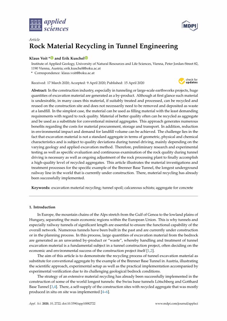
These calcareous schists of higher quality have been recycled at the processing plant that wasinstalled in 2014 using a three-stage rock crushing system followed by a high performing wet-processing(washing and sieving) of the aggregates at the area of the Padastertal landfill site (Figure 8). Theprocessed material was used primarily as supply of draining gravel of the particle size groups 16/32and 32/63 mm, aggregate for structural concrete, lining concrete as well as shotcrete. In November2014, the entire concrete production of shotcrete—that was needed for the excavation of the accesstunnel Wolf—was rearranged entirely using aggregate from the processed excavation material of theBündner Schist unit [39].
Appl. Sci. 2020, 10, 2722 11 of 16
Appl. Sci. 2019, 9, x FOR PEER REVIEW 13 of 18
a length of four kilometres was conventionally excavated in the period between 2013 and 2016. For this construction section, recycling of excavation material was not intended upfront, because the quality of the expected rocks of the Bündner Schist unit was not considered appropriate for reuse. The access tunnel is situated in Bündner Schist rocks that can be characterized as carbonate-rich schists and phyllites in alternating strata. There, the utilized excavation material consists of compact grey calcareous schists with an unconfined compressive strength of approximately 80 N/mm² with anisotropic, laminated to banked appearance (see Table 1). During blasting, grain diameters from 0 to ca. 700 mm were obtained.
These calcareous schists of higher quality have been recycled at the processing plant that was installed in 2014 using a three-stage rock crushing system followed by a high performing wet-processing (washing and sieving) of the aggregates at the area of the Padastertal landfill site (Figure 8). The processed material was used primarily as supply of draining gravel of the particle size groups 16/32 and 32/63 mm, aggregate for structural concrete, lining concrete as well as shotcrete. In November 2014, the entire concrete production of shotcrete—that was needed for the excavation of the access tunnel Wolf—was rearranged entirely using aggregate from the processed excavation material of the Bündner Schist unit [39].
Figure 8. Processing plant and aggregate production near the tunnel portal at the access tunnel Wolf.
5.2. Plant Concept
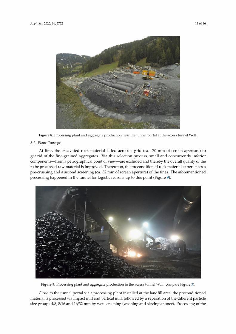
At first, the excavated rock material is led across a grid (ca. 70 mm of screen aperture) to get rid of the fine-grained aggregates. Via this selection process, small and concurrently inferior components—from a petrographical point of view—are excluded and thereby the overall quality of the to be processed raw material is improved. Thereupon, the preconditioned rock material experiences a pre-crushing and a second screening (ca. 32 mm of screen aperture) of the fines. The aforementioned processing happened in the tunnel for logistic reasons up to this point (Figure 9).
Figure 8. Processing plant and aggregate production near the tunnel portal at the access tunnel Wolf.
5.2. Plant Concept
At first, the excavated rock material is led across a grid (ca. 70 mm of screen aperture) toget rid of the fine-grained aggregates. Via this selection process, small and concurrently inferiorcomponents—from a petrographical point of view—are excluded and thereby the overall quality of theto be processed raw material is improved. Thereupon, the preconditioned rock material experiences apre-crushing and a second screening (ca. 32 mm of screen aperture) of the fines. The aforementionedprocessing happened in the tunnel for logistic reasons up to this point (Figure 9).Appl. Sci. 2019, 9, x FOR PEER REVIEW 14 of 18
Figure 9. Processing plant and aggregate production in the access tunnel Wolf (compare Figure 3).
Close to the tunnel portal via a processing plant installed at the landfill area, the preconditioned material is processed via impact mill and vertical mill, followed by a separation of the different particle size groups 4/8, 8/16 and 16/32 mm by wet-screening (washing and sieving at once). Processing of the sand fraction 0/4 mm is done via a bucket wheel. The accumulated fines <0.063 mm are flocculated and separated by filter bags in the provided filter basins (see Figure 7). Filtered water passes across a pipe system to the water protection system (setting of the pH-value and further deposition of remaining fines), finally reaching the receiving water. A compilation of the different processing steps is shown in Figure 10 [39].
Figure 10. Processing concept of excavated tunnel spoil [39].
Continuous supervision and monitoring of the aggregate quality were done within the scope of the European standard “aggregates for concrete” EN 12620 and Austrian standard “testing methods for concrete” ONR 23302. With an interval of one week, evaluations of grain size distribution and content of fines were carried out. Grain shape and concrete compressive strength of test specimen were evaluated on a monthly basis. Depending on this information, the concrete mix (above all
Figure 9. Processing plant and aggregate production in the access tunnel Wolf (compare Figure 3).
Close to the tunnel portal via a processing plant installed at the landfill area, the preconditionedmaterial is processed via impact mill and vertical mill, followed by a separation of the different particlesize groups 4/8, 8/16 and 16/32 mm by wet-screening (washing and sieving at once). Processing of the

Appl. Sci. 2020, 10, 2722 12 of 16
sand fraction 0/4 mm is done via a bucket wheel. The accumulated fines <0.063 mm are flocculated andseparated by filter bags in the provided filter basins (see Figure 7). Filtered water passes across a pipesystem to the water protection system (setting of the pH-value and further deposition of remainingfines), finally reaching the receiving water. A compilation of the different processing steps is shown inFigure 10 [39].
Appl. Sci. 2019, 9, x FOR PEER REVIEW 14 of 18
Figure 9. Processing plant and aggregate production in the access tunnel Wolf (compare Figure 3).
Close to the tunnel portal via a processing plant installed at the landfill area, the preconditioned material is processed via impact mill and vertical mill, followed by a separation of the different particle size groups 4/8, 8/16 and 16/32 mm by wet-screening (washing and sieving at once). Processing of the sand fraction 0/4 mm is done via a bucket wheel. The accumulated fines <0.063 mm are flocculated and separated by filter bags in the provided filter basins (see Figure 7). Filtered water passes across a pipe system to the water protection system (setting of the pH-value and further deposition of remaining fines), finally reaching the receiving water. A compilation of the different processing steps is shown in Figure 10 [39].
Figure 10. Processing concept of excavated tunnel spoil [39].
Continuous supervision and monitoring of the aggregate quality were done within the scope of the European standard “aggregates for concrete” EN 12620 and Austrian standard “testing methods for concrete” ONR 23302. With an interval of one week, evaluations of grain size distribution and content of fines were carried out. Grain shape and concrete compressive strength of test specimen were evaluated on a monthly basis. Depending on this information, the concrete mix (above all
Figure 10. Processing concept of excavated tunnel spoil [39].
Continuous supervision and monitoring of the aggregate quality were done within the scope ofthe European standard “aggregates for concrete” EN 12620 and Austrian standard “testing methodsfor concrete” ONR 23302. With an interval of one week, evaluations of grain size distribution andcontent of fines were carried out. Grain shape and concrete compressive strength of test specimenwere evaluated on a monthly basis. Depending on this information, the concrete mix (above all cementcontent and water/binder-ratio) was constantly adjusted. The examination of grain density and waterabsorption, freeze-thaw resistance, content of chloride and calcium carbonate as well as sulphur andhumus content were conducted several times a year. In a pre-measure, inferior rock material likecalcareous and graphitic phyllites are sorted out through rock identification at the tunnel face via thegeologists. Inferior material is disposed and therefore does not enter the conditioning process [39].
5.3. Characteristics of Produced Aggregate
Aggregate that was produced in the implemented processing plant (Figure 8) is showing adequateproperties in terms of grain size distribution, grain shape and content of fines. Particle size class 0/4mm demonstrates a continuous grain size distribution with a content of fines <0.063 mm of 4.4% and<0.02 mm of 2.2%, respectively.
The flakiness index (percentage of aggregate weight having an average least dimension of lessthan 0.6 times their average dimension; determined via grid sieves according to European standard EN933-3)—showing an appropriate magnitude for processed aggregate—is illustrated in Table 5 showingclear improvements in comparison to non-processed aggregate, compare Section 4.3 and Table 2.
The material properties as shown in Tables 1 and 5 demonstrate the usability for diverseapplications of the processed aggregate from the Bündner Schist rocks. Even high-quality applicationsfor the compensation of standard aggregate in concrete production are possible, reaching compressivestrengths for structural concrete of ca. 41.8 N/mm2, and in the case of shotcrete, ca. 42.8 N/mm2 duringconcrete production at the construction site at the access tunnel Wolf [39,40].

Appl. Sci. 2020, 10, 2722 13 of 16
Table 5. Flakiness index and fines for processed excavation material at the access tunnel Wolf.
Particle Size Class Flakiness Index FI [%] a) Category of Fines a)
4/8 mm 7 f1,58/16 mm 12 f1,516/32 mm 17 f1,5
a) in accordance with EN 12620.
5.4. Current Stage Regarding Excavation Material Processing
At present, in the case of the currently ongoing large-scale construction section Pfons–Brenner, thatstarted in autumn 2018, the reuse of rock material is a top priority. The construction lot itself includesthe excavation of ca. 37 km of the main tunnel section, ca. 9 km of exploratory tunnel as well as theconstruction of an emergency cavern. The rock will mostly be excavated by continuous tunnel drivingvia tunnel boring machine, affecting the properties of the excavated material (above all size and shapeof the rock aggregate; see Section 4.2). Significant attention will be devoted to quality managementdue to material use for high-grade concrete products such as inner shell or structural concrete.
6. Conclusions
Recycling of tunnel spoil is becoming increasingly important. This is not only because of the largeamounts of rock mass that are excavated that otherwise must be disposed of, but also because of risingshortage of mineral raw materials like sand and gravel in the Alpine valleys. In times of sustainability,resource efficiency and minimisation of emissions it is a logic decision to recycle and reuse excavatedtunnel spoil within the framework of the possibilities depending on rock material characteristics,processing effort and local demand for rock aggregate. By the given example of the Brenner BaseTunnel, it could be shown that even despite a restricted forecast concerning the possible recyclingextent due to moderate rock properties, Bündner Schist rocks could be recycled at the construction siteto produce value grain for drainage gravel and concrete aggregate manufacture.
In this paper, it is shown that for a successful recycling realization, extensive preliminary researchconcerning rock quality and concrete mix design, as well as an excellent technical implementationof the processing and concrete mixing plant are necessary. In an initial step, comprehensive rockcharacterisation is needed to identify the range of the existing rocks and their mechanical and chemicalproperties, whereby rock properties are dictated by the existing rock types. These experiments arefollowed by aggregate test production from excavated raw material recording data of attained aggregatecharacteristics and processing procedure. Here, the aim is to test different crusher and mill types,finding the optimal machines as well as instrument combinations for crushing and sieving to optimizethe geometric properties of the produced aggregates. The implementation of an efficient and powerfulprocessing facility plays a key role with regard to the recycling implementation success. In the case ofthe current example, a three-stage crushing system using a jaw crusher, impact mill and vertical mill aswell as an efficient wet processing including washing and sieving was applied to improve grain shapeto a preferably cubic shape as well as to significantly reduce the amount of fines. After optimizing theaggregate quality, concrete testing—also in accordance with the chemical composition of the sourcerock—is needed to find concrete mix designs for the different concrete types and applications ensuringhigh stability and durability of the concrete structures.
In the current example of the Brenner Base Tunnel, the extracted value aggregate could beprocessed and optimized for the application as aggregate for shotcrete, inner lining and structuralconcrete as well as filter gravel. Thus, the purchase and transport of aggregate from local quarrieswas minimized, and therefore resources were saved, accompanied by a financial benefit. In summary,through this example, it can be noted that reuse of tunnel spoil will also play an important role forfuture tunnel projects because of ecological and economic reasons.

Appl. Sci. 2020, 10, 2722 14 of 16
Author Contributions: Conceptualization, investigation and writing, K.V., investigation and software, E.K. Bothauthors have read and agree to the published version of the manuscript.
Funding: The open access funding was provided by BOKU Vienna Open Access Publishing Fund.
Acknowledgments: This research was carried out with the support of the Brenner Base Tunnel company BBT SE.The authors would like to acknowledge the technical and financial support.
Conflicts of Interest: The authors declare no conflict of interest.
References
1. ITA Report No. 21: Handling, Treatment and Disposal of Tunnel Spoil Materials; Working Groups 14 and15–Underground Construction and the Environment and Mechanized Tunneling; International Tunnelingand Underground Space Association ITA: Lausanne, Switzerland, 2019.
2. Ritter, S.; Einstein, H.; Galler, R. Planning the handling of tunnel excavation material–A process of decisionmaking under uncertainty. Tunn. Undergr. Space Technol. 2013, 33, 193–201. [CrossRef]
3. Lieb, R.H. Materials management at the Gotthard Base Tunnel—Experience from 15 years of construction.Geomech. Tunnelbau 2009, 2, 619–626. [CrossRef]
4. BLS AlpTransit Lötschberg: Final Report Logistics in Excavation and Material Management (SchlussberichtLogistik Ausbruch- und Materialbewirtschaftung); IG-LBT Ingenieurgemeinschaft Lötschberg-Basistunnel:Niedergesteln, Switzerland, 2008. (In German)
5. Thalmann, C. Ergänzende Prüfungen zu den bestehenden Beton-Normen für gebrocheneZuschlagstoffe–Erfahrungen beim AlpTransit Gotthard. Z. Schweiz. Ing. Archit. 1994, 24, 532–536.(In German)
6. Resch, D.; Lassnig, K.; Galler, R.; Ebner, F. Tunnel excavation material—High value raw material. Geomech.Tunnelbau 2009, 2, 612–618. [CrossRef]
7. Bellopede, R.; Brusco, F.; Oreste, P.; Pepino, M. Main Aspects of Tunnel Muck Recycling. Am. J. Environ. Sci.2011, 7, 338–347. [CrossRef]
8. Bellopede, R.; Marini, P. Aggregates from tunnel muck treatments. Properties and uses. Physicochem. Probl.Miner. Process. 2011, 47, 259–266.
9. Thalmann, C. Characterisation and Possibilities of the Utilisation of Excavated Rock Material by TunnelingBoring Machines as Concrete and Shotcrete Aggregates. Ph.D. Thesis, Swiss Federal Institute of TechnologyZurich (ETH), Zürich, Switzerland, 1996. (In German).
10. Gertsch, L.; Fjeld, A.; Nilsen, B.; Gertsch, R. Use of TBM muck as construction material. Tunn. Undergr. SpaceTechnol. 2000, 15, 379–402. [CrossRef]
11. Burger, D.; Kohlböck, B.; Schoitsch, C. Geotechnics and mass balance of the earthworks for the second tubeof the Tauern Tunnel. Geomech. Tunn. 2010, 3, 4. [CrossRef]
12. Riviera, P.P.; Bellopede, R.; Marini, P.; Bassani, M. Performance-based re-use of tunnel muck as granularmaterial for subgrade and sub-base formation in road construction. Tunn. Undergr. Space Technol. 2014, 40,160–173. [CrossRef]
13. Mlinar, C.; Sempelmann, F.; Koch, G.; Steiner, M.; Kubin, F. Tunnel spoil as a source of raw materials for anautobahn—Sustainable reuse of resources through the example of the S 10/Tunnelausbruch als Rohstoffquellefür eine Autobahn—Nachhaltige Ressourcenverwertung am Beispiel der S 10. Geomech. Tunnelbau 2014, 7,428–436. [CrossRef]
14. Raderbauer, B.; Wyss, A. Tunnel excavation material as resource for underground power plants and concretedam constructions/Tunnelausbruch als Rohstoff für den unterirdischen Kraftwerks- sowie Staumauerbau imHochgebirge. Geomech. Tunnelbau 2014, 7, 451–460. [CrossRef]
15. Oggeri, C.; Fenoglio, T.M.; Vinai, R. Tunnel spoil classification and applicability of lime addition in weakformations for muck reuse. Tunn. Undergr. Space Technol. 2014, 44, 97–107. [CrossRef]
16. Erben, H.; Galler, R. Tunnel spoil—New technologies on the way from waste to raw material/Tunnelausbruch—Neue Technologien für den Weg vom Abfall zum Rohstoff. Geomech. Tunnelbau 2014, 7, 402–410. [CrossRef]
17. Reichel, P. Tunnel spoil: Tipping or the end of the definition as waste/Tunnelausbruch: Deponierung oderAbfallende. Geomech. Tunnelbau 2014, 7, 419–427. [CrossRef]

Appl. Sci. 2020, 10, 2722 15 of 16
18. Danzer, M. Waste law framework for the recovery of material excavated from tunnels/AbfallrechtlicheRahmenbedingungen für die Verwertung von Tunnelausbruchmaterial. Geomech. Tunnelbau 2014, 7, 411–418.[CrossRef]
19. Posch, H.; Murr, R.; Huber, H.; Kager, M.; Kolb, E. Tunnel excavation—The conflict between waste andrecycling through the example of the Koralm Tunnel, contract KAT2/Tunnelausbruch—Das Spannungsfeldzwischen Abfall und Verwertung am Beispiel Koralmtunnel, Baulos KAT2. Geomech. Tunnelbau 2014, 7,437–450. [CrossRef]
20. EU Funded Research Project “DRAGON”. Available online: https://europa.eu/investeu/projects/dragon-%E2%80%93-innovative-approach-tunnelling_en (accessed on 7 April 2020).
21. Bergmeister, K.; Cordes, T.; Murr, R. Novel semiprobabilistic tunnel lining design approach with improvedconcrete mixture. Tunnels and Underground Cities: Engineering and Innovation meet Archaeology,Architecture and Art. In Proceedings of the WTC 2019 ITA-AITES World Tunnel Congress, Naples, Italy, 3–9May 2019; pp. 1714–1723.
22. Cordes, T.; Dummer, A.; Neuner, M.; Hofstetter, G.; Bergmeister, K. The load-bearing capacity of primarylinings with consideration of time-dependence at the Brenner Base Tunnel. In Proceedings of the ITA-AITESWorld Tunnel Congress 2019, Naples, Italy, 3–9 May 2019.
23. Dengg, F.; Zeman, O.; Voit, K.; Bergmeister, K. Fastening application in concrete using recycled tunnelexcavation material. Struct. Concr. 2017, 19, 374–386. [CrossRef]
24. Bergmeister, K.; Kogler, H.; Murr, R.; Cordes, T.; Arnold, R. Brenner Basistunnel–Innovationen zurAufbereitung des Tunnelausbruchmaterials und Optimierung der Betonzusammensetzung. Das größteTunnelbauprojekt Europas. Zement+Beton 2016, 1, 48–57.
25. Voit, K.; Zeman, O.; Murr, R.; Bergmeister, K.; Arnold, R. Aufbereitung und Wiederverwertung vonTunnelausbruchmaterial beim Brenner Basistunnel. Beton Stahlbetonbau 2015, 110, 832–844. [CrossRef]
26. BBT SE: UVE—Ausbruchmaterial und Eigenschaften. Technische Projektaufbereitung. Fachbereich Geologie,Geotechnik, Hydrogeologie. Haupttunnel; Technischer Bericht: Vienna, Austria, 2008.
27. BBT SE: Ausbruchmaterialbewirtschaftungskonzept. Eisenbahnrecht, Technische Projektaufbereitung. FachbereichBauphasen; KL-D0118-BR-04340-10; Technischer Bericht: Vienna, Austria, 2008.
28. Bergmeister, K. Brenner Basistunnel—Lebensräume und Verkehrswege; 1. Auflage; Tappeiner: Innsbruck, Austria,2008.
29. Brandner, R.; Reiter, F.; Töchterle, A. Überblick zu den Ergebnissen der geologischen Vorerkundung für denBrenner-Basistunnel. Geo. Alp. 2008, 5, 165–174.
30. Voit, K. Application and Optimization of Tunnel Excavation Material of the Brenner Base Tunnel. Ph.D.Thesis, University of Natural Resources and Life Sciences, Vienna, Vienna, Austria, 2013. (In German).
31. Voit, K.; Zimmermann, T. Characteristics of selected concrete with tunnel excavation material. Constr. Build.Mater. 2015, 101, 217–226. [CrossRef]
32. Maidl, B.; Jodl, H.G.; Schmid, L.R.; Petri, P. Tunnelbau im Sprengvortrieb; Glückauf: Berlin, German, 1997.33. An, H.; Liu, H.; Han, H.; Zheng, X.; Wang, X. Hybrid finite-discrete element modelling of dynamic fracture
and resultant fragment casting and muck-piling by rock blast. Comput. Geotech. 2017, 81, 322–345. [CrossRef]34. Yang, P.; Lei, Q.; Xiang, J.; Latham, J.-P.; Pain, C. Numerical simulation of blasting in confined fractured
rocks using an immersed-body fluid-solid interaction model. Tunn. Undergr. Space Technol. 2020, 98, 103352.[CrossRef]
35. Liu, R.; Zhu, Z.; Li, Y.; Liu, B.; Wan, D.; Li, M. Study of rock dynamic fracture toughness and crack propagationparameters of four brittle materials under blasting. Eng. Fract. Mech. 2020, 225, 106460. [CrossRef]
36. Girmscheid, G. Baubetrieb und Bauverfahren im Tunnelbau; Ernst & Sohn Verlag: Berlin, Germany, 2008.37. Li, G.; Wang, W.; Jing, Z.; Zuo, L.; Wang, F.; Wei, Z. Mechanism and numerical analysis of cutting rock and
soil by TBM cutting tools. Tunn. Undergr. Space Technol. 2018, 81, 428–437. [CrossRef]38. Yin, L.; Miao, C.; He, G.; Dai, F.; Gong, Q. Study on the influence of joint spacing on rock fragmentation
under TBM cutter by linear cutting test. Tunn. Undergr. Space Technol. 2016, 57, 137–144. [CrossRef]

Appl. Sci. 2020, 10, 2722 16 of 16
39. Voit, K. Recycling of Tunnel Spoil. Ph.D. Thesis, University of Natural Resources and Life Sciences, Vienna,Vienna, Austria, 2016. (In German).
40. Murr, R.; Cordes, T.; Hofmann, M.; Bergmeister, K. Autarkic aggregate supply with recycled tunnel spoil atthe Brenner Base Tunnel. Tunnels and Underground Cities: Engineering and Innovation meet Archaeology,Architecture and Art. In Proceedings of the WTC 2019 ITA-AITES World Tunnel Congress, Naples, Italy, 3–9May 2019; pp. 495–504.
© 2020 by the authors. Licensee MDPI, Basel, Switzerland. This article is an open accessarticle distributed under the terms and conditions of the Creative Commons Attribution(CC BY) license (http://creativecommons.org/licenses/by/4.0/).